Embed Size (px)
Citation preview

OpenStax-CNX module: m22937 1
DTMF Detection*
Jacob Fainguelernt
This work is produced by OpenStax-CNX and licensed under the
Creative Commons Attribution License 2.0�
Abstract
This module shows the implementation of a DTMF detector using the DSK6713. The detector is
desgined using Simulink.
1 Introduction
The Dual-tone multi-frequency (DTMF) signaling method was developed originally to replace pulse1 (DialPulse or DP in the U.S.2 ) and loop disconnect (LD) signaling methods to dial numbers, in order to shortenthe holding time of the switch during dialing , specially for long distance calls.
DTMF signaling uses two tones to represent each key on the touch pad. There are 12 distinct tones3
(Please refer to Table 1). When any key is pressed the tone of the column and the tone of the row aregenerated. As an example, pressing the '5' button generates the tones 770 Hz and 1336 Hz. The frequencieswere chosen to avoid harmonics: no frequency is a multiple of another, the di�erence between any twofrequencies does not equal any of the frequencies, and the sum of any two frequencies does not equal any ofthe frequencies.
. 1209 Hz 1336 Hz 1477 Hz
697 Hz 1 2 3
770 Hz 4 5 6
852 Hz 7 8 9
941 Hz * 0 #
Table 1: DTMF Frequencies
Table 1- DTMF frequenciesThe low frequencies are referred as rows, The higher frequencies are referred as columns.This example will show the implementation of a DTMF receiver using the DSK6713. The DTMF receiver
will be based on the simulation model used in the Simulink demo. A graphic user interface (GUI) will alsobe created to activate the DSK6713. DTMF digits will be sent from the PC sound card.
*Version 1.2: May 5, 2009 1:31 am -0500�http://creativecommons.org/licenses/by/2.0/1http://en.wikipedia.org/wiki/Pulse_dialing2http://en.wikipedia.org/wiki/United_States3The DTMF method de�nes four additional digits: �A�, �B�,�C� & �D�. Most of the systems today do not use those digits.
http://cnx.org/content/m22937/1.2/
OpenStax-CNX module: m22937 2
1.1 Related Files
• Powerpoint Presentation - DTMF.ppt4
• Simulink Model for Simulation - DTMF.mdl5
• MATLAB GUI for Real-Time - DTMF.�g6
• GUI m-�le - DTMF.m7
• Simulink Model for Real-Time - DTMF_DSK6713.mdl8
2 Simulation
2.1 The Simulation Model
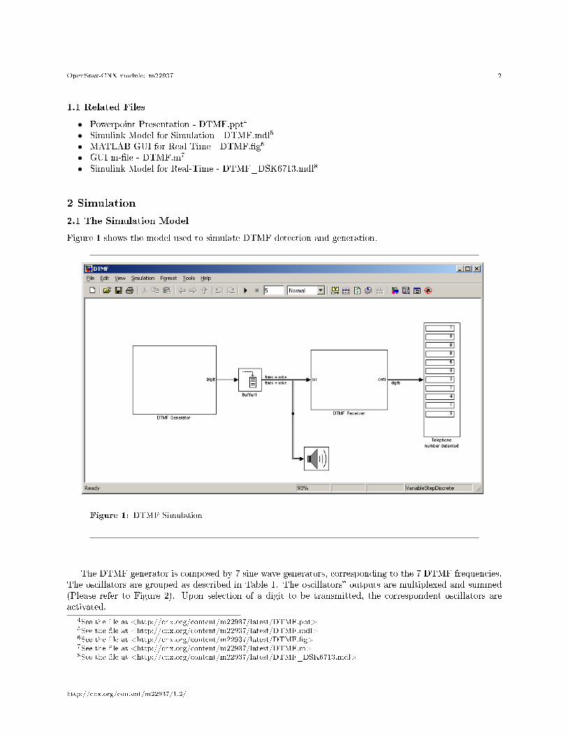
Figure 1 shows the model used to simulate DTMF detection and generation.
Figure 1: DTMF Simulation
The DTMF generator is composed by 7 sine wave generators, corresponding to the 7 DTMF frequencies.The oscillators are grouped as described in Table 1. The oscillators� outputs are multiplexed and summed(Please refer to Figure 2). Upon selection of a digit to be transmitted, the correspondent oscillators areactivated.
4See the �le at <http://cnx.org/content/m22937/latest/DTMF.ppt>5See the �le at <http://cnx.org/content/m22937/latest/DTMF.mdl>6See the �le at <http://cnx.org/content/m22937/latest/DTMF.�g>7See the �le at <http://cnx.org/content/m22937/latest/DTMF.m>8See the �le at <http://cnx.org/content/m22937/latest/DTMF_DSK6713.mdl>
http://cnx.org/content/m22937/1.2/

OpenStax-CNX module: m22937 3
Figure 2: DTMF Generation
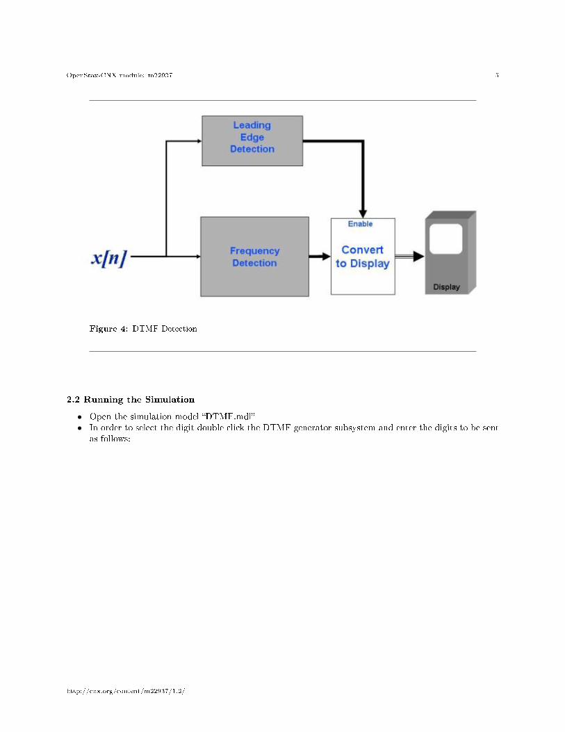
The DTMF detection comprises two processes, the frequency detection algorithm itself, and a leadingedge detection subsystem.
The frequency detection subsystem measures the energy present at the seven frequencies, and calculatesthe digit by taking the component of maximum energy in the lower and upper frequency groups. The processis shown in Figure 3. This process runs continuously; however the calculated digit is reported only if itsenergy is above a threshold as determined by the leading edge detection subsystem. The DTMF detectionprocess is shown in Figure 4.
http://cnx.org/content/m22937/1.2/

OpenStax-CNX module: m22937 4
Figure 3: Frequency Detection
http://cnx.org/content/m22937/1.2/
OpenStax-CNX module: m22937 5
Figure 4: DTMF Detection
2.2 Running the Simulation
• Open the simulation model �DTMF.mdl�• In order to select the digit double click the DTMF generator subsystem and enter the digits to be sent
as follows:
http://cnx.org/content/m22937/1.2/

OpenStax-CNX module: m22937 6
Figure 5: "Dialing" DTMF Digits
• Activate the simulation, the detected digits will be displayed as shown:
http://cnx.org/content/m22937/1.2/
OpenStax-CNX module: m22937 7
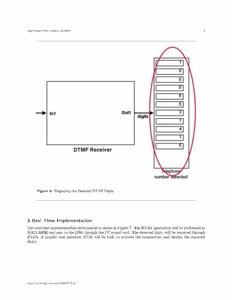
Figure 6: Displaying the Detected DTMF Digits
3 Real Time Implementation
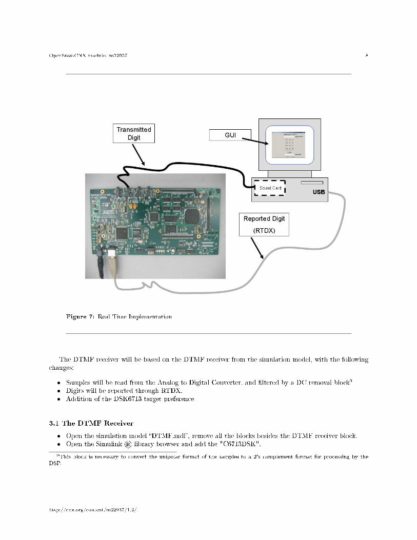
The real-time implementation environment is shown in Figure 7. The DTMF generation will be performed inMATLAB® and sent to the DSK through the PC sound card. The detected digits will be reported throughRTDX. A graphic user interface (GUI) will be built to activate the transmitter, and display the reporteddigits.
http://cnx.org/content/m22937/1.2/
OpenStax-CNX module: m22937 8
Figure 7: Real Time Implementation
The DTMF receiver will be based on the DTMF receiver from the simulation model, with the followingchanges:
• Samples will be read from the Analog to Digital Converter, and �ltered by a DC removal block9
• Digits will be reported through RTDX.• Addition of the DSK6713 target preference
3.1 The DTMF Receiver
• Open the simulation model �DTMF.mdl�, remove all the blocks besides the DTMF receiver block.• Open the Simulink ® library browser and add the "C6713DSK".
9This block is necessary to convert the unipolar format of the samples to a 2's complement format for processing by theDSP.
http://cnx.org/content/m22937/1.2/

OpenStax-CNX module: m22937 9
Figure 8: The C6713DSK target Block
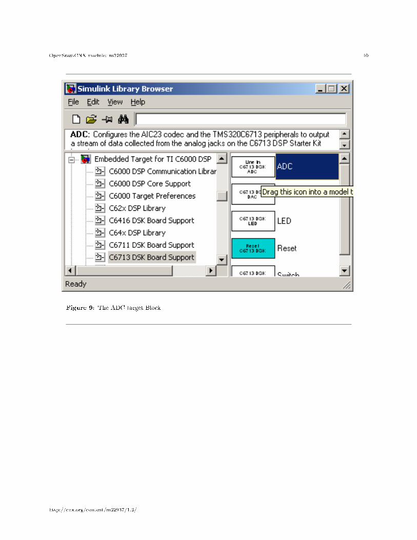
• Add the �Analog to Digital� � converter (ADC) to your model:
http://cnx.org/content/m22937/1.2/
OpenStax-CNX module: m22937 10
Figure 9: The ADC target Block
http://cnx.org/content/m22937/1.2/
OpenStax-CNX module: m22937 11
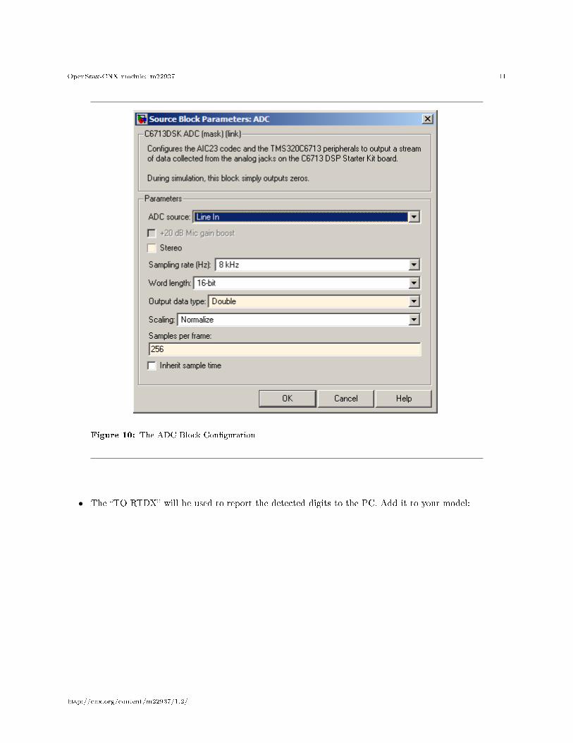
Figure 10: The ADC Block Con�guration
• The �TO RTDX� will be used to report the detected digits to the PC. Add it to your model:
http://cnx.org/content/m22937/1.2/

OpenStax-CNX module: m22937 12
Figure 11: The "To RTDX" Block
http://cnx.org/content/m22937/1.2/
OpenStax-CNX module: m22937 13
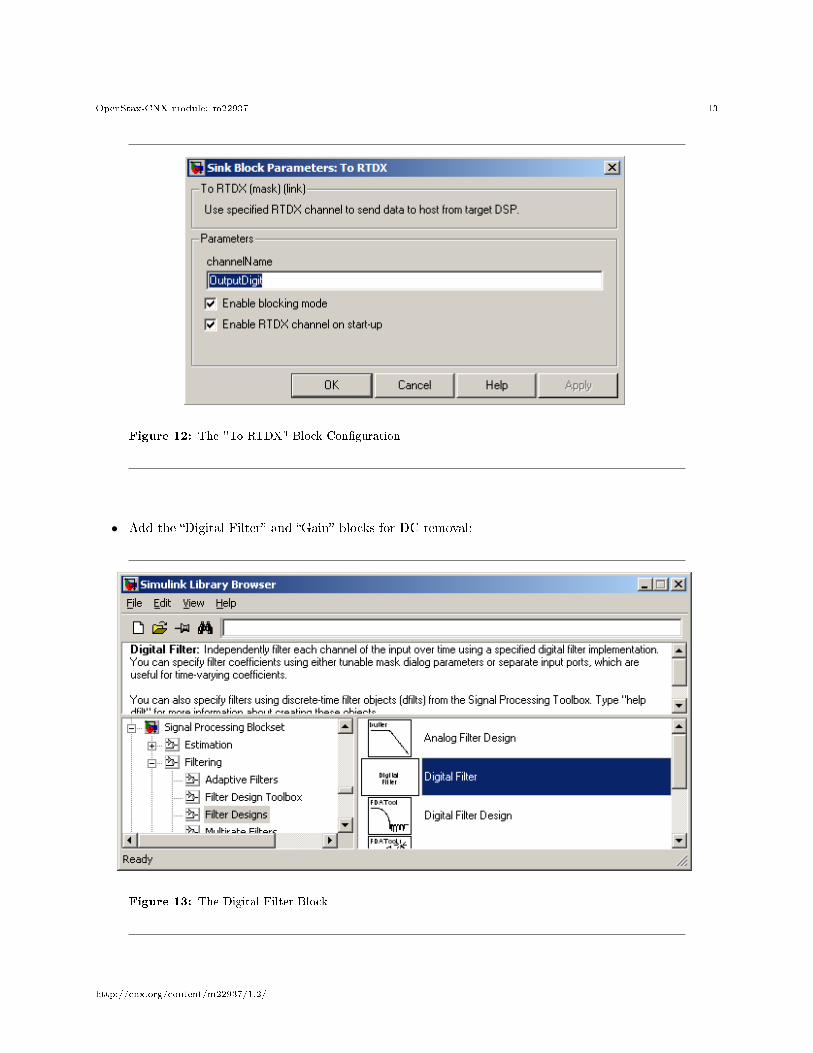
Figure 12: The "To RTDX" Block Con�guration
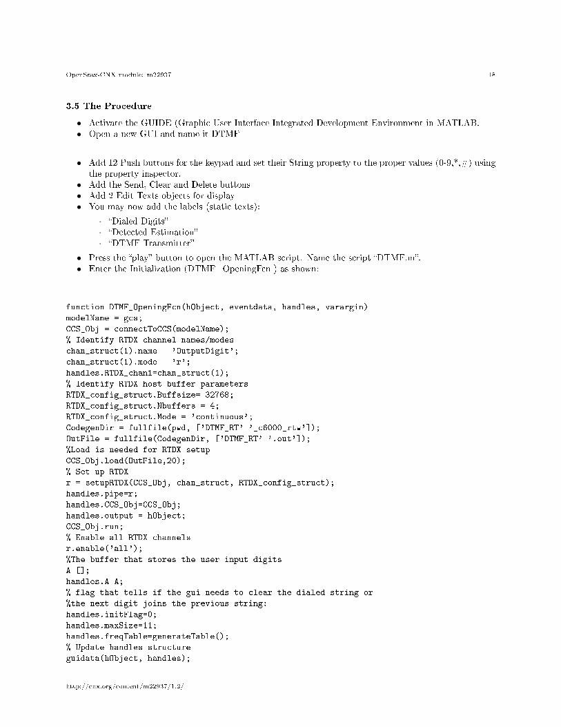
• Add the �Digital Filter� and �Gain� blocks for DC removal:
Figure 13: The Digital Filter Block
http://cnx.org/content/m22937/1.2/

OpenStax-CNX module: m22937 14
Figure 14: The Digital Filter Block Con�guration
http://cnx.org/content/m22937/1.2/

OpenStax-CNX module: m22937 15
Figure 15: The Gain Block
Figure 16: The Gain Block Con�guration
http://cnx.org/content/m22937/1.2/

OpenStax-CNX module: m22937 16
• The DTMF receiver model is shown Figure 17:
Figure 17: DTMF Receiver
• Save the model as "DTMF_DSK6713.mdl".• Built the model.
3.2 The User Interface
3.3 Functionality
The GUI will perform the following functions:
• Initialization: Initialize the RTDX interface and loading the DTMF Receiver program we have builtin the last section to the DSK.
• Generate the DTMF signal samples: The GUI will enable the user to select a sequence of 11 digits10
to be transmitted. It will create the samples of the DTMF signal based on this selection, and sendthem to the sound card.
• Display the detected digits reported by the DSK
10If the user selects less than 11 digits, the sequence is padded with DTMF digit '1'.
http://cnx.org/content/m22937/1.2/

OpenStax-CNX module: m22937 17
3.4 Description
The desired GUI is shown in Figure 18
Figure 18: DTMF GUI
It will enable the user to:
• Dial the digits: every digit dialed is added to a speci�c bu�er, and displayed under the �Dialed Digits�label.
• Delete the last digit• Clear all the digits• Send: Create the DTMF signal from the digits selected11. A dual-tone signal will be created for each
digit. Silence will be inserted between consecutive digits. This signal is sent to the sound blaster usingthe �sound� command in MATLAB.
• Display: Digits reported by the DSK will be displayed under the �Detected Digits� label.
11The DSK operates with a bu�er of 11 digits so if the user dialed less then 11 digits we are padding them to 11 in theMATLAB.
http://cnx.org/content/m22937/1.2/
OpenStax-CNX module: m22937 18
3.5 The Procedure
• Activate the GUIDE (Graphic User Interface Integrated Development Environment in MATLAB.• Open a new GUI and name it DTMF
• Add 12 Push buttons for the keypad and set their String property to the proper values (0-9,*,#) usingthe property inspector.
• Add the Send, Clear and Delete buttons• Add 2 Edit Texts objects for display• You may now add the labels (static texts):
· �Dialed Digits�· �Detected Estimation�· �DTMF Transmitter�
• Press the �play� button to open the MATLAB script. Name the script �DTMF.m�.• Enter the Initialization (DTMF_OpeningFcn ) as shown:
function DTMF_OpeningFcn(hObject, eventdata, handles, varargin)
modelName = gcs;
CCS_Obj = connectToCCS(modelName);
% Identify RTDX channel names/modes
chan_struct(1).name = 'OutputDigit';
chan_struct(1).mode = 'r';
handles.RTDX_chan1=chan_struct(1);
% Identify RTDX host buffer parameters
RTDX_config_struct.Buffsize= 32768;
RTDX_config_struct.Nbuffers = 4;
RTDX_config_struct.Mode = 'continuous';
CodegenDir = fullfile(pwd, ['DTMF_RT' '_c6000_rtw']);
OutFile = fullfile(CodegenDir, ['DTMF_RT' '.out']);
%Load is needed for RTDX setup
CCS_Obj.load(OutFile,20);
% Set up RTDX
r = setupRTDX(CCS_Obj, chan_struct, RTDX_config_struct);
handles.pipe=r;
handles.CCS_Obj=CCS_Obj;
handles.output = hObject;
CCS_Obj.run;
% Enable all RTDX channels
r.enable('all');
%The buffer that stores the user input digits
A=[];
handles.A=A;
% flag that tells if the gui needs to clear the dialed string or
%the next digit joins the previous string:
handles.initFlag=0;
handles.maxSize=11;
handles.freqTable=generateTable();
% Update handles structure
guidata(hObject, handles);
http://cnx.org/content/m22937/1.2/
OpenStax-CNX module: m22937 19
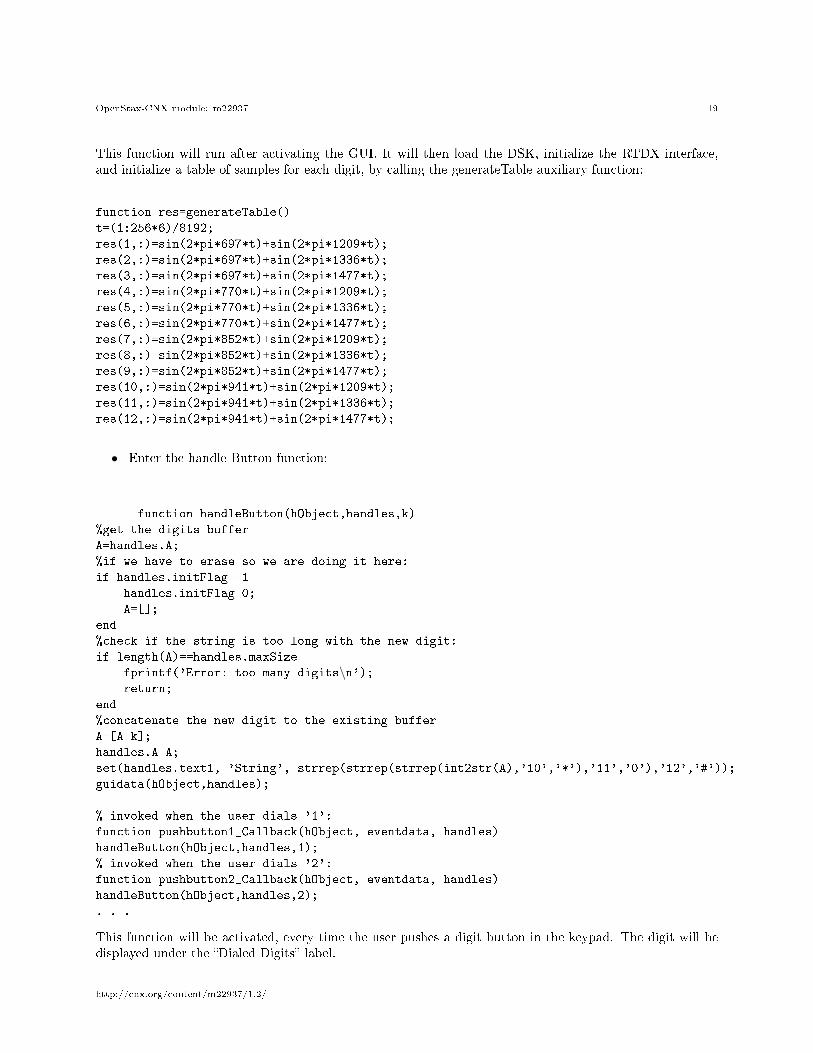
This function will run after activating the GUI. It will then load the DSK, initialize the RTDX interface,and initialize a table of samples for each digit, by calling the generateTable auxiliary function:
function res=generateTable()
t=(1:256*6)/8192;
res(1,:)=sin(2*pi*697*t)+sin(2*pi*1209*t);
res(2,:)=sin(2*pi*697*t)+sin(2*pi*1336*t);
res(3,:)=sin(2*pi*697*t)+sin(2*pi*1477*t);
res(4,:)=sin(2*pi*770*t)+sin(2*pi*1209*t);
res(5,:)=sin(2*pi*770*t)+sin(2*pi*1336*t);
res(6,:)=sin(2*pi*770*t)+sin(2*pi*1477*t);
res(7,:)=sin(2*pi*852*t)+sin(2*pi*1209*t);
res(8,:)=sin(2*pi*852*t)+sin(2*pi*1336*t);
res(9,:)=sin(2*pi*852*t)+sin(2*pi*1477*t);
res(10,:)=sin(2*pi*941*t)+sin(2*pi*1209*t);
res(11,:)=sin(2*pi*941*t)+sin(2*pi*1336*t);
res(12,:)=sin(2*pi*941*t)+sin(2*pi*1477*t);
• Enter the handle Button function:
function handleButton(hObject,handles,k)
%get the digits buffer
A=handles.A;
%if we have to erase so we are doing it here:
if handles.initFlag==1
handles.initFlag=0;
A=[];
end
%check if the string is too long with the new digit:
if length(A)==handles.maxSize
fprintf('Error: too many digits\n');return;
end
%concatenate the new digit to the existing buffer
A=[A k];
handles.A=A;
set(handles.text1, 'String', strrep(strrep(strrep(int2str(A),'10','*'),'11','0'),'12','#'));
guidata(hObject,handles);
% invoked when the user dials '1':
function pushbutton1_Callback(hObject, eventdata, handles)
handleButton(hObject,handles,1);
% invoked when the user dials '2':
function pushbutton2_Callback(hObject, eventdata, handles)
handleButton(hObject,handles,2);
. . .
This function will be activated, every time the user pushes a digit button in the keypad. The digit will bedisplayed under the �Dialed Digits� label.
http://cnx.org/content/m22937/1.2/
OpenStax-CNX module: m22937 20
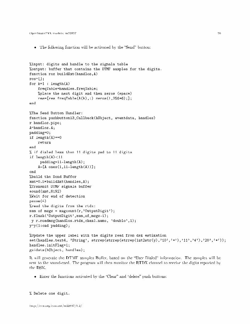
• The following function will be activated by the �Send� button:
%input: digits and handle to the signals table
%output: buffer that contains the DTMF samples for the digits.
function res=buildXmt(handles,A)
res=[];
for k=1 : length(A)
freqTable=handles.freqTable;
%place the next digit and then zeros (space)
res=[res freqTable(A(k),:) zeros(1,256*6);];
end
%The Send Button Handler:
function pushbutton13_Callback(hObject, eventdata, handles)
r=handles.pipe;
A=handles.A;
padding=0;
if length(A)==0
return
end
% if dialed less than 11 digits pad to 11 digits
if length(A)<11padding=11-length(A);
A=[A ones(1,11-length(A))];
end
%build the Send Buffer
xmt=0.5*buildXmt(handles,A);
%Transmit DTMF signals buffer
sound(xmt,8192)
%Wait for end of detection
pause(4)
%read the digits from the rtdx:
num_of_msgs = msgcount(r,'OutputDigit');
r.flush('OutputDigit',num_of_msgs-1);
y=r.readmsg(handles.rtdx_chan1.name, 'double',1);
y=y(1:end-padding);
%Update the upper label with the digits read from dsk estimation
set(handles.text4, 'String', strrep(strrep(strrep(int2str(y),'10','*'),'11','#'),'20','*'));
handles.initFlag=1;
guidata(hObject, handles);
It will generate the DTMF samples Bu�er, based on the �User Dialed� information. The samples will besent to the sound-card. The program will then monitor the RTDX channel to receive the digits reported bythe DSK.
• Enter the functions activated by the �Clear� and �delete� push buttons:
% Delete one digit.
http://cnx.org/content/m22937/1.2/

OpenStax-CNX module: m22937 21
function pushbutton14_Callback(hObject, eventdata, handles)
A=handles.A;
if length(A)==0
return
end
A=A(1:end-1);
set(handles.text1, 'String', strrep(strrep(strrep(int2str(A),'10','*'),'11','0'),'12','#'));
handles.A=A;
guidata(hObject, handles);
%Clear all the dialed digits.
function pushbutton15_Callback(hObject, eventdata, handles)
A=handles.A;
A=[];
set(handles.text1, 'String',
strrep(strrep(strrep(int2str(A),'10','*'),'11','0'),'12','#'));
handles.A=A;
guidata(hObject, handles);
3.6 Running the Example
The system used to run this example is shown in Figure 7.Activate the GUI (DTMF.�g). Enter an array of digits and compare them to those detected by the DSK.
4 Things to Try
The original algorithm (simulation) runs in a "noiseless" environment. You are invited to check the perfor-mance of the real-time model, and eventually change the algorithm to reduce its sensitivity to noise.
You may also add new buttons for DTMF parameters (level, frequency deviation, etc . . .), and test theDTMF receiver performance against these parameters.
MATLAB and Simulink are registered trademarks of The MathWorks, Inc. See www.mathworks.com/trademarksfor a list of additional trademarks. Other product or brand names may be trademarks or registered trade-marks of their respective holders.
http://cnx.org/content/m22937/1.2/