Embed Size (px)
Citation preview

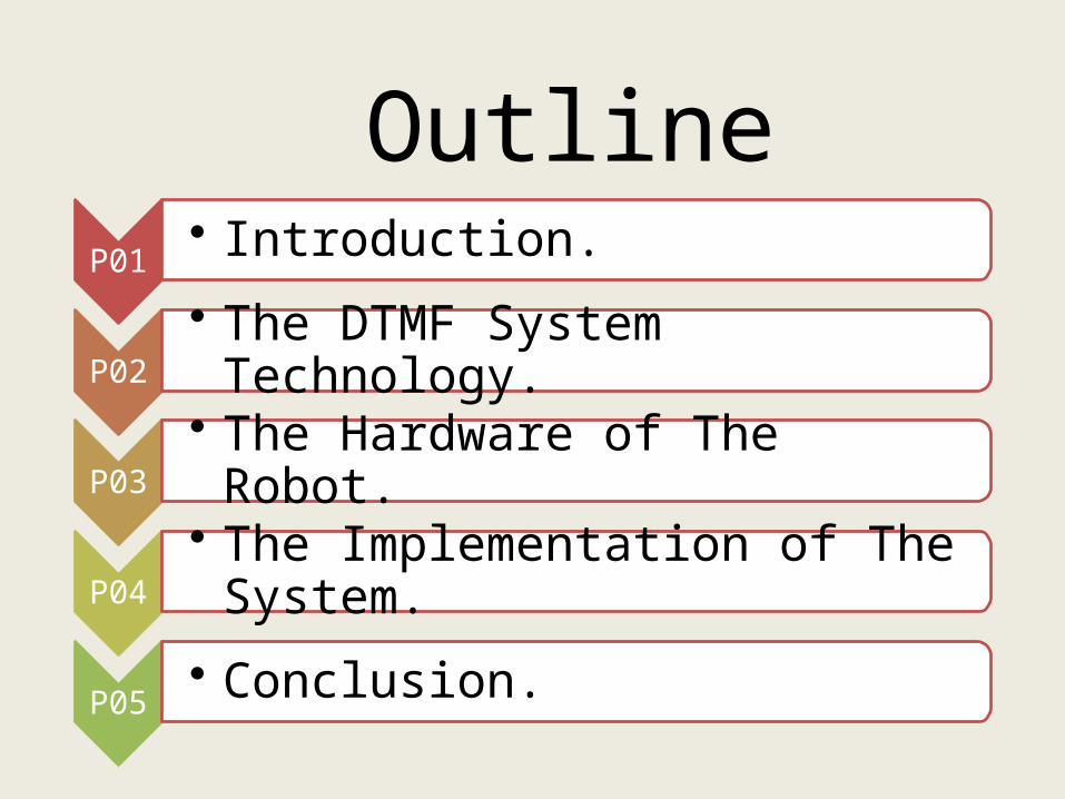
P01
• Introduction.
P02
• The DTMF System Technology.
P03
• The Hardware of The Robot.
P04
• The Implementation of The System.
P05
• Conclusion.
Outline
Controlling a robot wirelessly is possible with several methods such as Remote, Bluetooth, Wi-Fi, etc. But, the controls of these communication methods are limited to certain areas, and complicated to design as well.A Mobile Controlled Robot is a solution to overcome these difficulties.
1.Introduction
A Mobile Controlled Robot is a mobile device, which provides wide-range of wireless control ability to your robot unless your cell phone gets out of signal.A general concept of mobile controlled robot is that it can be controlled from any part of the world
Robotics has been a dominant contributor to the development of the human society over the years.
1
# The Control of robot involves three distinct phases:
perception, processing and action.
- Generally, the preceptors are sensors mounted on the robot.- processing is done by the on-board microcontroller or processor.- The task is performed using motors or with some other actuators.
1.Introduction
2

Before DTMF was created, telephone networks used a system called Decadic. This system was used extensively in telephone networks to dial numbers, it was very useful system, but limited to the local exchange connections requiring an operator to connect long distance calls.
In the late years of 1950, DTMF was being developed for the purpose of allowing tone signals to dial long distance numbers, which could be potentially be dialed not only via standard wire networks, but also via radio links .
The version of DTMF used for telephone tone dialing is known by the trademarked term “Touch-Tone”.
2.DTMF System Technology
1. History
3
2. DTMF Basics
DTMF (Dual Tone Multi Frequency) is a system of signal tones used in telecommunication.
As its acronym suggests, a valid DTMF signal is a tone composed of two sine (cos) waves given frequencies to each key.
Individual frequencies are chosen so that it is quite easy can be identified by the electronic circuit and can easily pass through telephone lines.
2.DTMF System Technology
4
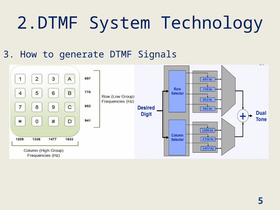
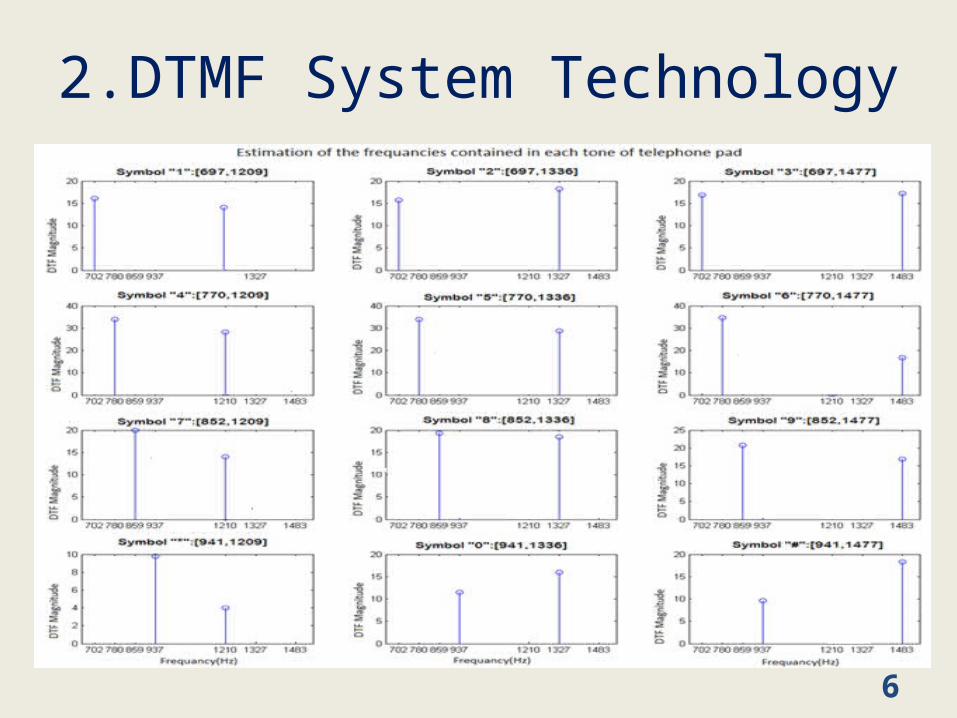
The signal generated by the DTMF encoder is a direct algebraic summation of “the amplitudes”, of two tones of different frequencies, one from a low group (697-941Hz) and the other from a high group (1209-1633Hz) with each group containing four individual tones.
2.DTMF System Technology
3. How to generate DTMF Signals
5
2.DTMF System Technology
6
4. DTMF Usage
Dual-tone multi-frequency signaling is used for telecommunication signaling over analog telephone lines between telephone handsets and other communications devices.Also used to switch adverts on TV, and in other domains (Military, Scientific…)
2.DTMF System Technology
7

3. Robot Hardware 1. DTMF receiver / decoder (CM8870))
8
Its internal architecture consists of :
1.Filter section : separates the high and Low frequency tones
2.Decoder section : determines the frequencies of the incoming tones and to verify that they correspond to the standard DTMF frequency.
3.Steering circuit : Before registration of a decoder tone pair, the receiver checks for a valid signal.
4.Clock circuit : The clock is completed with addition of external 3.58MHzcrystal oscillator.
3. Robot Hardware
9
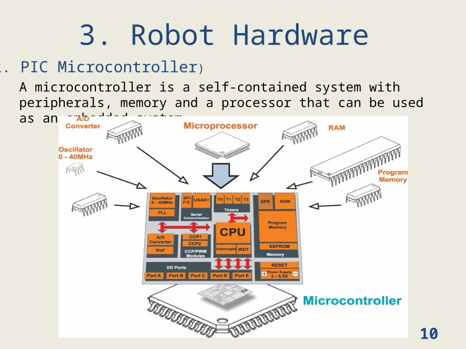
A microcontroller is a self-contained system with peripherals, memory and a processor that can be used as an embedded system.
3. Robot Hardware 2. PIC Microcontroller)
10
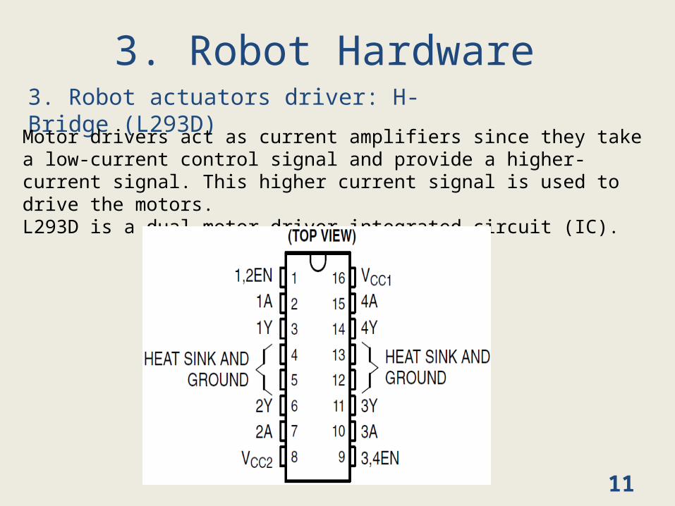
3. Robot actuators driver: H-Bridge (L293D)
3. Robot Hardware Motor drivers act as current amplifiers since they take a low-current control signal and provide a higher-current signal. This higher current signal is used to drive the motors.L293D is a dual motor driver integrated circuit (IC).
11
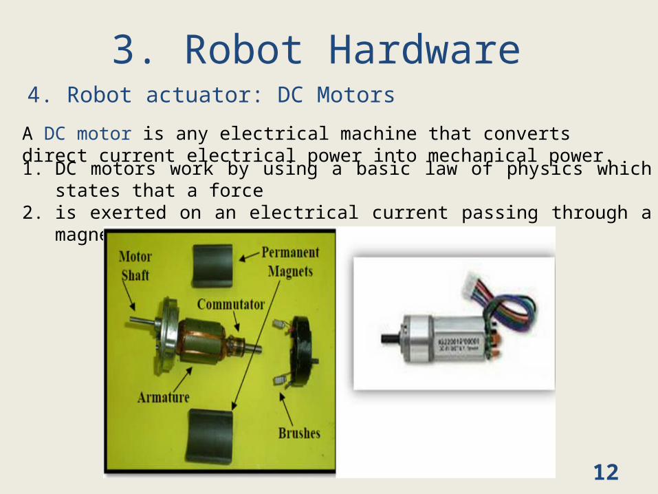
4. Robot actuator: DC Motors
3. Robot Hardware A DC motor is any electrical machine that converts direct current electrical power into mechanical power.1. DC motors work by using a basic law of physics which states
that a force 2. is exerted on an electrical current passing through a magnetic
field.
12
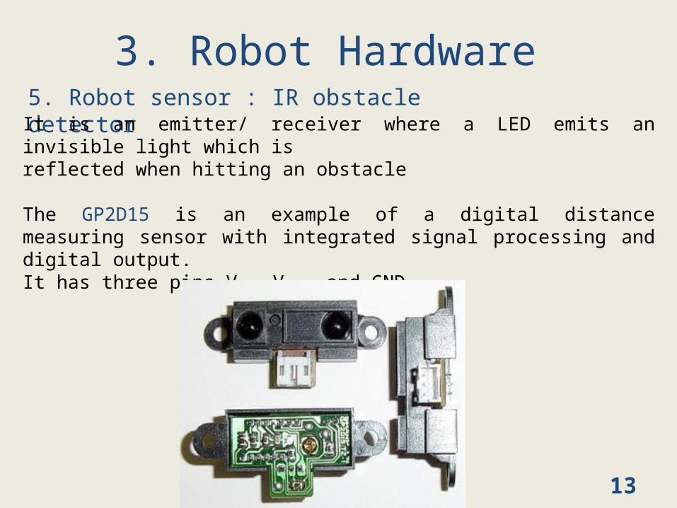
5. Robot sensor : IR obstacle detector
3. Robot Hardware It is an emitter/ receiver where a LED emits an invisible light which is reflected when hitting an obstacle
The GP2D15 is an example of a digital distance measuring sensor with integrated signal processing and digital output. It has three pins Vin, Vout, and GND.
13
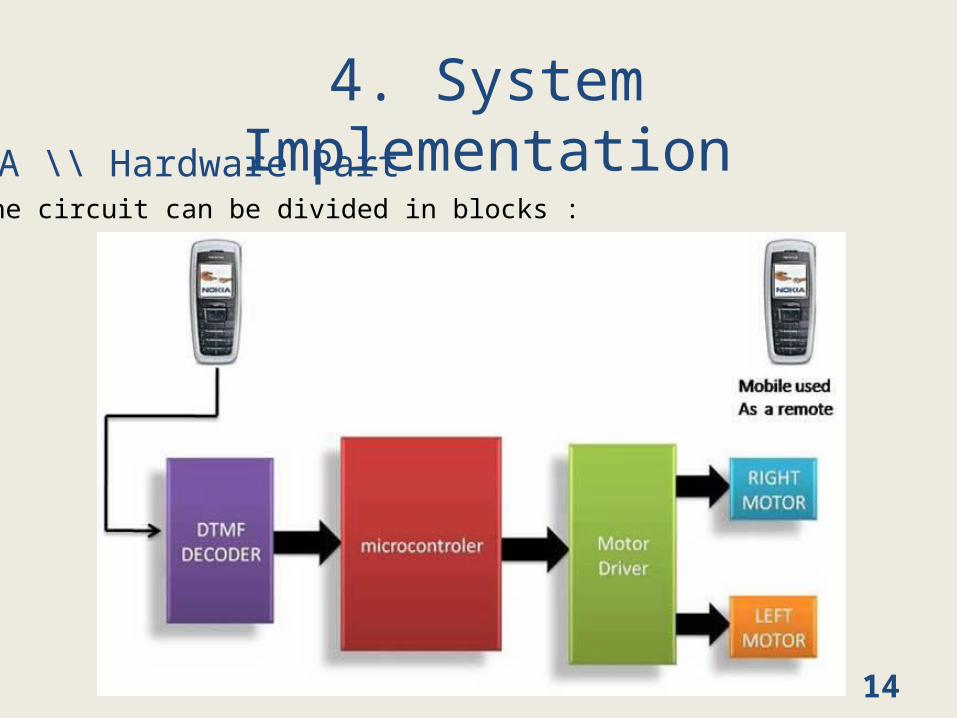
4. System ImplementationA \\ Hardware Part
The circuit can be divided in blocks :
14
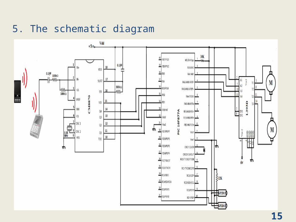
5. The schematic diagram
15
B \\ Software PartB.1 Writing the codeWe use a high level language which is MikroC which is basically a C with some custom extensions and libraries.
B.2 Compiling the CodeMikroC PRO for PIC is used to compile the C program. It is a Windows-based Integrated Development Environment of mikroElektronika, used for PIC microcontroller .
B.3 Simulating the codeTo simulate the code execution we can use PROTEUS virtual System Modeling (VSM).
B.4 Loading the code The PICkit 2 programmer is used to load the program into the PIC16877A. It is connected to the PC via USB port.
16
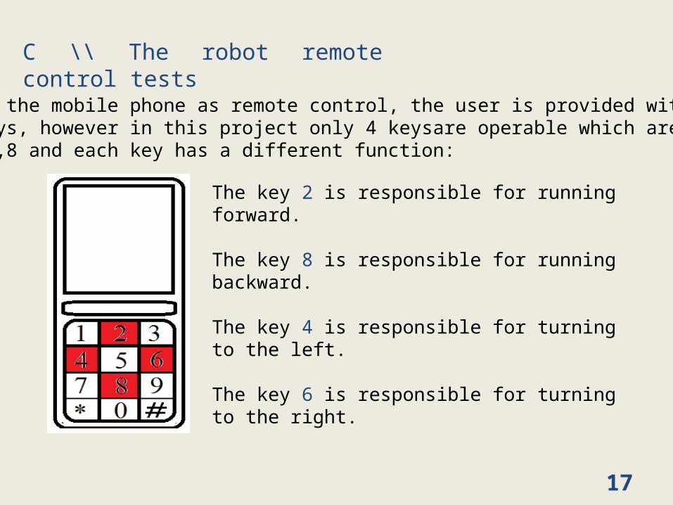
C \\ The robot remote control tests
Using the mobile phone as remote control, the user is provided with 12 keys, however in this project only 4 keysare operable which are: 2,4,6,8 and each key has a different function:
The key 2 is responsible for running forward.
The key 8 is responsible for running backward.
The key 4 is responsible for turning to the left.
The key 6 is responsible for turning to the right.
17
5. ConclusionThis report presents a useful way to control a robot, which is performed using the DTMF tones generated by the phone.
It presents several advantages like the large range of working distance and the robustness of control with respect to the communication interference.
However, it is not flexible with all cell phones, and mobile batteries drain out early so charging problem.
18

19


![[MS-DTMF]: RTP Payload for DTMF Digits, Telephony Tones](https://img.pdfslide.us/doc/110x75/618761294ef0486d5b31de99/ms-dtmf-rtp-payload-for-dtmf-digits-telephony-tones-.jpg)