Embed Size (px)
Citation preview

TEC-0007 AD-A252
Intelligent TDA SystemsUsing Neural NetworksPhase I Final Report
iii= DT'C
Richard H. Stottler JUL 0 9 1992i Andrea L. Henke A
IAI Stottler Henke Associates, Inc.
916 Holly RoadI Belmont, CA 94002
* May 1992
Approved for public release; distribution is unlimited.
92'II U.S. Army Corps of Engineers
Topographic Engineering CenterFort Belvoir, Virginia 22060-5546 92-1770492-17704 '

I,. * ' °"i
iIiii
Destroy this report when no longer needed.Do not return it to the originator.
IThe findings in this report are not to be construed as an officialDepartment of the Army position unless so designated by otherauthorized documents.
The citation in this report of trade names of commercially available products does notconstitute official endorsement or approval of the use of such products.
IIIIIIII
REPORT DOCUMENTATION PAGE form pp7o4edI OMe NO. 0704-08
P.,&K~ ro.1N bufldel tot INSi (OJItC1( OtOf to &-C 'Ie age 8. ' -0.- Der lso~se. n<., l q- th'e lq.~~o ' ' fotrc o~ W.'C,,,g . n dot. o cr~h.a d .~ the data neded. a,4 (t-olt," ard 8 e. 9 the colecto0' 0f -to-s~t On . ~m.tt Se", vgt' bde~ ft~lJ@0 ~other *%Den of ttt
*ItCo rnfo."#.On..f .n9 ugruosto t rd.-g thm bwo,a. to wahN~ "eadq.vanrle SeN w 't oa. bu w1 r-tt OAeton " 'e CaOr , el
06.. "ho.ga Sn '204. £thngltont. V '2120241102 O)d 10 tIC Off '( Of andq~l~ 4t4 udgtt PSPCt'0t% RedgWton Pro,,," (0704.0 'iS). Wsafthgton. OC 205031. AGENCY USE ONLY (Leave blank) 2. REPORT DATE 3. REPORT TYPE AND DATES COVEREDMay 1992 Technical Report October 1991 - May 1992
4. TITLE AND SUBTITLE S. FUNDING NUMBERS
Intelligent TDA Systems Using Neural Networks Phase IFinal Report
6. AUTHOR(S)
Richard H. StottlerAndrea L. Henke
7. PERFORMING ORGANIZATION NAME(S) AND ADORESS(ES) S. PERFORMING ORGANIZATION
Stottler Henke Associates, Inc. REPORT NUMBER
916 Holly RoadBelmont, CA 94002
9. SPONSORING[MONITORING AGENCY NAME(S) AND ADORfSS(ES) 10. SPONSORING /MONITORING
AGENCY REPORT NUMBER
U.S. Army Topographic Engineering Center
Fort Belvoir, VA 22060-5546 TEC-0007
1l. SUPPLEMENTARY NOTES
Effective 1 October 1991, the U.S. Army Engineer Topographic Laboratories (ETL) became theU.S. Army Topographic Engineering Center (TEC).
i2a. DISTRIBUTION /AVAILABILITY STATEMENT i2b. DISTRIBUTION CODE
Approved for public release; distribution is unlimited.
13. ABSTRACT (Maximum 200 words)
The overall objective of Phase I was to develop a prototype intelligent Tactical Decision Aids (TDA) neuralnetwork system through the use of an expert system to neural network translator. From the resultingprototype network, the performance of the complete TDA system could be determined. The Phase I resultsabsolutely demonstrated the feasibility of this concept and cleared the way for development of a completesystem in Phase ff. Current TDA systems require too much expertise from the user and run too slowly foruse in tactical situations, when time is in short supply. In tactical situations, terrain is an extremely importantfactor and represents one of the main inputs to these systems. The Airborne Avenues of Approach (AAA)Planning problem was chosen. While initial route planning is performed prior to the start of the mission, aneed exists to automate and speed the process. Additionally, a system which could meet the rigorous real-timerequirements of an on-board AAA re-planner would prove enormously beneficial in many time-critical tacticalsituations.
14. SUBJECT TERMS IS. NUMBER Of PAGES
Helicopter Path Planning, Helicopter Avenues of Approach, Airborne Avenues 72of Approach, Artificial Intelligence, Tactical Decision Aids, Translation IL PRICE CODENeural Networks, Expert Systems17. SECURITY CLASSIFICATION IS. SECURITY CLASSIFICATION 19. SECURITY CLASSIFICATION 20. LIMITATION OF ABSTRACT
OF REPORT OF THIS PAGE OF ABSTRACT
SINCL SIS D 1UNCLASSIFIED UNCLASSIFIED UNLIMITEDNSN 7540-01-280-5S00 Standaid Form 290 (Rev 2-89)

Table of Contents
Section Pae
1.0 PREFACE ................................................. v
2.0 SUMARY ................................................. 1
3.0 PROJECT OBJECTIVES .............. ...................... 23.1 Identification and Significance of the Problem ........ 23.1.1 Airborne Avenues of Approach ...................... 33.1.2 Characteristics of Expert Systems ................ 33.1.3 Characteristics of Neural Networks ............... 43.1.4 Opportunity ........................................ 53.1.5 Innovations ........................................ 63.2 Statement of Objectives ................................ 6
4.0 WORK DESCRIPTION ........................................74.1 Approach ................................................ 74.2 Task Descriptions ....................................... 74.2.1 Identify Tactical Decision Aids (TDA) Problem .... 74.2.2 Knowledge Engineering ............................. 84.2.3 Translate Expert System to Neural Network
Representation ...................................4.2.3.1 Update Prototype Translator ................. S4.2.3.2 Develop Additional Translation Strategies ... 94.2.3.3 Implement Additional Translation Strategies4.2.4 Design and Implement Demonstration Application4.2.5 Design Phase II Software Architecture ............ .4.2.6 Determine Performance of Final System ............ 94.2.7 Prepare Final Report .............................. 9
5.0 TECHNICAL RESULTS AND PHASE I ACCOMPLISHMENTS ......... 115.1 Summarv of Results ..................................... 115.2 TDA Problem Selection and Analysis .................... 115.3 Knowledae Enaineerina Results ......................... 125.3.1 Knowledae Gatherina .............................. 125.3.2 Knowledge Implementation ......................... 155.4 Translation Results ................................... 165.4.1 Translation Strateaies ........................... 165.4.1.1 Expert System Conceets ........................ 65.4.1.2 Translatable Concepts ....................... 175.4.1.3 Untranslatable ConceDts ..................... 175.4.1.4 The Loaic Network Representation ............ 185.4.1.5 The Neural Network Representation ........... 195.4.1.6 Additional Strateaies ....................... 195.4.2 Architecture of the Translator ................... 205.4.3 Translator Updatina Results ...................... 225.4.4 Translator Performance Results ................... 225.5 Phase II Software Architecture ........................ 23
ii

5.6 Phase II Predicted Performance ........................ 25
6.0 TECHNICAL FEASIBILITY ................................. 27
7.0 FUTURE RESEARCH AND DEVELOPMENT ....................... 287.1 Future Development .................................... 287.1.1 Helicopter Avenues of Approach TDA Development ...287.1.2 Improvements to the Translator ................... 297.2 Future Research ........................ 307.2.1 Adaptability ..................................... 317.2.2 Fault Tolerance .................................. 307.2.3 Generalization ................................... 317.2.4 Neural Structuring ............................... 317.2.4 Optimizations .................................... 32
8.0 CONCLUSIONS ............................................. 34
APPENDIX A PHASE II DESIGN ............................. 35
APPENDIX B COMPLETE TRANSLATION STRATEGIES ............. 40B.1 Rule to Logic Network Translation ..................... 40B.1.1 Logic Network Description ........................ 40B.1.2 Rule to Logic Network Translation Strategies ..... 43B.2 Logic Network to Neural Network Translation ........... 45B.2.1 Neural Network Target Representation ............. 45B.2.2 Logic Network to Neural Network Translation ...... 45B.3 Additional Translation Strategies ..................... 52B.3.1 Rating Summation ................................. 52B.3.2 Route Planning ................................... 53
APPENDIX C DESCRIPTION OF HELICOPTER PROOF OF CONCEPTPROTOTYPE ................................... 56
APPENDIX D EXPERT SYSTEM RULE-BASE ..................... 58
Accesion ForNTIS CRA&IOTIC TABEUnannounced
Justifica tioii
By
- Availabiity Codes
) Dist ASpucial
IA1

I List of Figures
FiueFQ
I5-1 Translator Architecture................................. 21
5-2 Phase II Software Architecture.......................... 24
IA-i Phase II Software Architecture.......................... 35A-2 Landform Identification Neural Network Layers........... 36A-3 Polygon Combiner........................................ 37IA-4 AAA Planner Expert System Development................... 37A-5 Expert System to Neural Network Translation............. 37A-6 AAA Planner Configuration............................... 38
B-i Gate Truth Tables....................................... 40B-2 Simple Antecedent Logic Network......................... 42B-3 Simple Consequent Logic Network......................... 42IB-4 Complex And Antecedent Logic Network.................... 43B-5 Complex Or Antecedent Logic Network..................... 44B-6 Real And Configuration.................................. 47IB-7 Real Or Configuration................................... 47B-8 Real Not Configuration.................................. 48B-9 Real Then Configuration................................. 48B-10 Real Unknown Configuration.............................. 49B-li Binary And Configuration................................ 50B-12 Binary or configuration................................. 50B-13 Binary Not Configuration................................ 51IB-14 Binary Then Configuration............................... 51B-i5 Before Translation...................................... 52B-16 After Translation....................................... 52IB-i7 Route Planner Fragment.................................. 54B-18 Binary Nin Gate......................................... 55B-19 Same Gate...........................55B-20 Sum Gate................................................. 55
C-i Polygon Hap Display.................................................. 56
I C-2 Route Display....... .................................................. 57
I iv

I
i 1.0 PREFACE
This report was prepared under Contract DACA76-91-C-0026 forthe U.S. Army Topographic Engineering Center, Fort Belvoir,Virginia 22060-5546 by Stottler Henke Associates, Inc., Belmont,California 94002. The Contracting Officer's Representative wasI James A. Shine.
IIIIIIIIIiiII
I

2.0 SUMMARY
The overall objective of Phase I was to develop a prototypeintelligent Tactical Decision Aids (TDA) neural network systemthrough the use of an expert system to neural network translator.From the resulting prototype network, the performance of thecomplete TDA system could be determined. The Phase I resultsabsolutely demonstrated the feasibility of this concept and clearedthe way for development of a complete system in Phase II.
Current TDA systems require too much expertise from the userand run too slowly for use in tactical situations, when time is inshort supply. In tactical situations, terrain is an extremelyimportant factor and represents one of the main inputs to thesesystems.
Our approach was to first choose a particular domain. TheAirborne Avenues of Approach (AAA) Planning problem is asignificant one in the TDA class of problems. While initial routeplanning is performed prior to the start of the mission, a needexists to automate and speed the process. Additionally a systemwhich could meet the rigorous real-time requirements of an on-boardAAA re-planner would prove enormously beneficial in many time-critical tactical situations.
The relevant knowledge was gathered and the system designed.We implemented the prototype solution with expert systemtechnology. We then completely translated that system to a neuralnetwork representation using our automatic translator. Thenetwork's performance was evaluated using test cases and a neuralnetwork simulator. Additionally, the performance of the completedPhase II system was estimated. The time to completely plan a routein a 100 mile by 100 mile area was conservatively estimated to be3 seconds with a $4000 specialized board and a 486-based PC.
There are many potential applications of this research. Themost direct application will be for Airborne Avenues of ApproachPlanning. This technology could be applied to many route planningproblems including Avenues of Approach for ground units. Thetechniques used here would benefit any application involving theintelligent evaluation of a large number of items. Examplesinclude threat evaluation and image understanding. Finally, thegeneric translator can be used to allow almost any expert system tobe translated to a neural network and thus receive the combinedbenefits of each technology.
1

3.0 PROJECT OBJECTIVES
The overall objective of Phase I was to develop a prototypeintelligent Tactical Decision Aids (TDA) neural network system.This was accomplished by developing a prototype expert system, andconverting it to a neural network representation using StottlerHenke Associates, Inc.'s (SHAI) automatic expert system to neuralnetwork translator. From the resulting prototype network, theperformance of the complete TDA system could be determined. Thisincludes the required number of neurons and interconnections, andthe processing speed required to meet real-time constraints. ThePhase I tasks absolutely demonstrated the feasibility of thisconcept and cleared the way for development of a complete system inPhase II. The Phase II Design is given in Appendix A.
3.1 Identification and Significance of the Problem
Current TDA systems require too much expertise from the userand run too slowly for use in tactical situations, when time is inshort supply. In order for the system to require less userexpertise, raw data must be accessed directly by the systems,without any intervention or processing by the user. In tacticalsituations, terrain is an extremely important factor and representsone of the main inputs for the systems. Terrain data can beaccessed directly from the Geographic Information System (GIS)which stores it along with other data, requiring much lessinvolvement from the user.
The opportunity presented by this project is to applyintelligent methods which utilize both terrain information storedin a GIS, and other information available in real-time such asweather, field observations, and remote sensor system data. Suchan intelligence can be easily approximated with expert systemtechnology. However, the expert system will run too slowly to meetthe rigorous real-time constraints of a tactical situation. It isalso very difficult to tune the approximation to a completelycorrect solution. Additionally, expert systems are not fault-tolerant, adaptable, or generalizing. But, if the expert systemapproximation could be transformed into a neural network and itsperformance tuned through training, then the network would possessthe high degree of intelligence easily implemented with expertsystem technology, run in real-time on neural network hardware, andrealize other benefits of neural networks such as fault-tolerance,adaptation, and the ability to generalize.
Of course for the network to process the needed informationmost efficiently, it should also be in a parallel form. This isespecially true for the terrain data, since it drives the decisionprocesses of the TDA systems and also represents a very largevolume of information. If the terrain data is available before theTDA systems must operate, the GIS information can also be converted
2

to a neural form so both the inference and the information uponwhich it operates are parallelized.
A GIS represents terrain data as a set of polygons, each ofwhich has borders in two- or three- dimensional space.Additionally, associated with each polygon are attributes of thepiece of terrain the polygon represents. The polygons can berepresented in the artificial intelligence (AI) knowledgerepresentation of a frame in a straightforward manner. Theseframes can then be linked to the expert system and the entirepackage translated to a neural network for parallel processing.Such a translation could occur almost as fast as the data can betransferred from the GIS.
3.1.1 Airborne Avenues of Approach
Airborne Avenues of Approach (AAA) Planning is a significantproblem in the TDA class of problems. While initial route planningis performed prior to the start of the mission, a need exists toautomate and speed the process. Additionally a system, which couldmeet the rigorous real-time requirements of an on-board AAA re-planner, would prove enormously beneficial in many time-criticaltactical situations.
The AAA Planner needs the high level of intelligencerepresentable with expert system technology both from a correctnessand from a understandability standpoint. Such a system alsorequires enormous data processing which indicates a need forparallelization to achieve the required speed. In addition, as inany fielded airborne, tactical system, fault-tolerance is extremelyimportant. The AAA Planner is an ideal candidate for the use ofSHAI's expert system to neural network translation technology.
3.1.2 Characteristics of Expert Systems
Expert systems represent knowledge as an explicit collectionof facts, rules, and frames and provide inference procedures formanipulating this information. Because the facts, rules, andframes are not encoded as programs, knowledge can be added to theexpert system knowledge-base or changed without affecting otherexisting knowledge. In addition, because the knowledge is declaredexplicitly rather than embedded in application procedures, it isstraightforward to understand and can be used for many diversepurposes. This eliminates the need and potential problem ofstoring facts multiple times, once for each type of application.A declarative representation allows knowledge to be extended by areasoning process and accessed by introspective programs, enablingthe system to answer questions about what it knows.
The major drawback of expert systems is that reasoning overdeclarative information tends to be inefficient. This is becausethe knowledge is represented independent of procedures for
3

utilizing it, and because expert systems are generally run onserial single processor machines. In addition, altering aninference engine and/or an expert system to directly run on aparallel processor machine is extremely difficult. Devising ageneral method for dividing a problem into sub-problems which canbe solved on multiple processors and then recombining theirsolutions is not a well-understood process.
Several other shortcomings arise because of the static natureof expert systems. Expert systems do not exhibit adaptablebehavior. For example, if an expert system derives an answer andreceives feedback that the answer is incorrect, we would like theexpert system to change its behavior for the future. In addition,expert systems are unable to generalize from a set of examples inan inductive manner. While machine learning offers great potentialin both these areas, it is still very much a difficult researchtopic. Human intervention is still required to modify an expertsystem's characteristics.
Expert systems are intolerant to variations in input.Consider, for example, the following expert system rule:
if A and B and C then D
The designer of the expert system may have assumed that fullknowledge of the truth of A, B, and C would be available at thetime this rule was checked. If A, B and C are available and true,D can be concluded. It may be the case, in some unusualcircumstance, that only two of these three antecedents are known.While we may prefer the expert system to compromise and concludethat D is almost true, it is unable to conclude anything.
Finally, expert systems are not fault tolerant during hardwarefailure. As software, an expert system usually will crashcompletely or produce unreliable results after a hardware failure.
3.1.3 Characteristics of Neural Networks
Neural networks are composed of simple analog processingelements. Each processing element has any number of inputs and asingle output. The output value is computed according to thefollowing strategy:
1) Perform a weighted sum of the inputs,2) Perform a simple function on that sum.
The output of a prucessing element is connected to the inputs ofmany other processing elements. Each connection has a weightassociated with it which is used in the weighted sum computation.
Some of the inputs to processing elements are connected to the
external world, as are some of the outputs. A neural network can
4

learn if it is presented a set of inputs and a set of desiredoutputs. The learning results by slightly changing the neuralnetwork's weights according to a learning algorithm.
Neural networks are a simple, but powerful parallel processingparadigm, offering the potential for a very large number ofprocessing elements. Neural networks can be implemented inhardware or simulated in software. Implementation of a neuralnetwork on a parallel processing machine is straightforward.Implementation of- a neural network is generally accomplished bydividing the processing elements among the available processors.Each processor simulates the functioning and interconnections ofthe processing elements allocated to it. By properly allocatingthe processing elements, full utilization of the multipleprocessors is possible.
Unlike expert systems, neural networks are adaptable and faulttolerant and can generalize solutions to problems. The primaryshortcoming of neural networ' s is that they are difficult to designand understand. This is be,.'se the knowledge they use to solveproblems is represented by interconnection weights, which are un-intuitive.
3.1.4 Opportunity
While expert systems are among the most common and successfulAl systems, their slowness and fragility prevent their applicationdirectly to the Airborne Avenues of Approach Planner. However, bytranslating a rule and frame based AAA Planner into a neuralnetwork representation, performance is dramatically improvedthrough parallelization and we derive the combined benefits ofexpert systems and neural networks. The performance improvement isdramatic enough to permit operation of the AAA Planner on-board thehelicopter. The resulting system is adaptable, fault tolerant andeasy to understand because of its expert system origin. The neuralnetwork representation can be implemented on parallel processingmachines or neural network hardware.
Currently, neural network hardware with a large number ofprocessing elements is available and orders of magnitudeimprovements in this number can be expected periodically. Thecombined processing power of these elements is much greater thanthat of conventional super computers. For example, while the Cray2 can process 35 million connections per second, a single low-costchip from Intel, the 80170NX, can process 2 billion connections persecond. Expert systems can take full advantage of this power withthe automatic expert system to neural network translation facilitynow developed.
The opportunity is to greatly improve on-board tacticaldecision making through the use of terrain data and otherenvironmental information processed with an intelligent AAA neural
5

n network developed through the use of an expert system translatorand training, which tunes the resulting network's performance. Theexpert system origin allows the final AAA neural network to possessa degree of intelligence impossible from the use of neural networktechnology alone.
3.1.5 Innovations
Significant innovations were applied to this project. First,an Airborne Avenues of Approach Planner was developed utilizingstandard AI techniques. The concept of translating this into aneural network is itself innovative. Few other researchers areworking on the problem of translating implemented expert systems toa neural network representation. Furthermore, each binding foreach rule-object combination can be represented in parallel.Finally, the combination of all the techniques to produce a workingexpert system to neural network translator is not only innovative,but many would have thought it impossible.
n 3.2 Statement of Objectives
Specifically, there were three technical objectives all ofwhich were met. A fourth objective, to improve the network'sperformance through training, was considered but later droppedbecause the network's performance did not need improvement.
1. Develop an intelligent TDA system using conventional expertsystem technology.
m 2. Translate the expert system into a neural network.
3. Determine the performance of the complete TDA system,n implemented in neural network hardware.
l 6
I

I
I 4.0 WORK DESCRIPTION
4.1 Approach
To achieve the primary project objective of developing anintelligent system which aids in tactical decisions based on bothterrain data stored in a GIS and other environmental information,we identified a number of tasks to be carried out over the Phase Iperiod. These tasks are listed below:
I Phase I Tasks
1. Identify the TDA problem.
2. Perform knowledge engineering.
3. Translate the expert system to a neural network representationusing the automatic translator.
* 4. Demonstrate the Application
5. Design the Phase II System
n 6. Determine the Performance of the Final System
7. Write the Phase I Final Report.
Our approach was to first identify the TDA problem. We chosea particular domain, determined what information was available andwhat was considered a correct decision based on this information.Second, the relevant knowledge was gathered and the systemdesigned. Third, we implemented the prototype solution with expertsystem technology. We then translated that system to a neuralnetwork representation using the automatic translator. Thenetwork's performance was evaluated using test cases and a neuralnetwork simulator. Additionally, the performance of the completedPhase II system was estimated. Finally, the effort and resultswere documented in this Final Report.
I 4.2 Task Descriptions
4.2.1 Identify Tactical Decision Aids (TDA) Problem
This task consisted of a number of steps. First, theparticular domain was identified. Possibilities included supplyfacilities location, sensor system site allocation, main battleI unit movement corridor identification, integrated air defenseplanning, integrated defensive fire support planning, JointSurveillance and Target Attack Radar System (JSTARS) patrollingpatterns, smart weapons deployment, and Airborne Avenues ofApproach (AAA). Then, performance criteria were identified. This
7
I
involved answering the following questions. What constitutescorrect decisions based on the terrain and other informationavailable? What are the real-time constraints? What informationis available on which to base decisions? Will the network bedirectly connected to this source of information? Is the source ofinformation hardware parallel in nature? Additionally, sources ofdomain knowledge had to be identified and training sets of data hadto be gathered for testing and training.
4.2.2 Knowledge Engineering
This task included both knowledge acquisition and the designof the expert system. The following questions had to be answered:What conditions will the TDA face? What factors must be*considered? Using the answers to these questions and consideringthat the expert system would be translated to a neural network, theexpert system was designed. Considerations included how best torepresent the knowledge to take advantage of the particularbenefits resulting from the neural network translation.
For example, each polygon of the terrain information wasrepresented as a frame. The polygon frame included slots to holdthe spatial information such as the polygon border information andadjacent polygons, ground type, vegcetation, and other informationwhich could be used to make intelligent decisions.
The knowledge-based solution was implemented usingIntellicorp's KAPPA expert system development tool. Theimplementation contained rules for intelligent tactical decisionmaking. For example, when determining the best terrain for ahelicopter avenue of approach, several factors were considered.The terrain should be shielded from enemy weapons systems. Shadowscast by the helicopter onto the terrain should be difficult to spotfrom the air. Preferably the terrain should be free from enemyground units as well.
4.2.3 Translate Expert System to Neural Network Representation
The expert system was translated to a neural networkrepresentation using the automatic translator. Some procedural,numeric code needed to be approximated by small networks which weredesigned and translated separately from the main expert systemnetwork. Additionally, the inputs and outputs to the translatednetwork were connected to a simple interface for demonstrationpurposes. The translation task consisted of a number of steps.
4.2.3.1 Update Prototype Translator
The translator was written in the summer of 1990. It neededto be updated to 1992 software standards. The intervening twoyears produced two major updates of KAPPA. The translator needed
8

I
to be ported across these updates. In addition, certainsimplifications in the operation of the translator were developed.
I 4.2.3.2 Develop Additional Translation Strategies
Two additional types of translation were added to thetranslator. Both were particular to this application. One was toallow the summation of the polygon ratings inside of the networkinstead of a virtual processor (see Appendix B for a description oftranslation elements and strategies). The other was to use theratings to perform route planning within the neural network. An
additional step was to assemble the input vectors for each polygonseparately from running the network for that polygon. This way thevector could be assembled ahead of time, which is closer to how thefinal Phase II system would operate.
4.2.3.3 Implement Additional Translation Strategies
The additional translation strategies were implemented ineither Kappa or C, whichever was most expedient for each. The codeto create the vector assembler was written in Kappa as was the codeto translate the summations. The code to translate the routeplanniag algorithm was written in C. The neural networksimulations were all in C.
1 4.2.4 Design and Implement Demonstration Application
A demonstration AAA Planner was designed and implemented.This included a user interface to allow the Planner to beI demonstrated. The purpose of this step was to show the flavor ofthe final Phase II system and prove that the intelligent neuralnetwork was possible.
4.2.5 Design Phase II Software Architecture
Based on performance and hardware considerations, the AAAPlanner to be implemented in Phase II was designed. This design iscarefully documented and explained in Section 5.5.
4.2.6 Determine Performance of Final System
The performance of the neural network prototype was evaluatedthrough a simulation testing phase. The simulation allowed us todetermine what percentage of the time the network performscorrectly and in which situations, and whether decisions can bereached with the existing neural network hardware and real-timeconstraints. From this prototype, performance criteria of thecompleted system implemented in neural network hardware can also beestimated. The number of neurons created and the hardwareavailable to simulate them was a major factor in the calculation ofthe expected performance.
9
4.2.7 Prepare Final Report
This final report documents the work performed in Phase I andlays the groundwork for Phase II. Specifically, the results of theevaluation of the prototype and the estimated performance of thecompleted Phase II system are detailed.
10

5.0 TECHNICAL RESULTS AND PHASE I ACCOMPLISHMENTS
5.1 Summary of Results
The AAA Planner was selected as the TDA problem solution forimplementation and translation. Knowledge sources consistingprimarily of Army documents were identified. Knowledge wasextracted and implemented in IntelliCorp's Expert System BuildingTool, Kappa. This expert system was completely translated into aneural network representation using both generic and AAA Plannerspecific strategies. Based on this Phase I experience, a Phase IIsystem was designed and its performance was estimated. The time tocompletely plan a route in a 100 mile by 100 mile area wasI conservatively estimated to be 3 seconds with a $4000 specializedboard and a 486-based PC.
5.2 TDA Problem Selection and Analysis
Although the AAA Planner was ultimately chosen as the bestTDA, it was not our only possibility. The other possibilitiesincluded supply facilities location, sensor system site allocation,main battle unit movement corridor identification, integrated airdefense pl~nning, integrated defensive fire support planning, JointSurveillance and Target Attack Radar System (JSTARS) patrollingpatterns, and smart weapons deployment.
TEC suggested that we choose a battlefield domain for theexpert system implementation. Given this guidance and our owndomain knowledge we eliminated supply facilities location andsensor system site allocation, leaving the five other domains. Weresearched various tactical domains and identified possible sourcesof knowledge for particular domains and narrowed our choices downto fire support, defense setup against tanks, and the groundavenues of approach.
We chose the ground avenues of approach domain and began workusing terrain information gathered during a previous project. Wedeveloped rules which considered slope, elevation, soil type,weight bearing ability of the soil, tree density, vegetation, andtype of vehicle. The rule base evaluated the traversability ofpolygons to certain types of vehicles. We also began formulatingthe route planning method used by the ultimate AAA Planner.
We then attended a meeting at TEC to discuss the particulardirection and enhancements of the ground avenues of approachplanner. At that time we discovered much work had already beendone in the ground avenues of approach domain and that a need wasanticipated for a helicopter or airborne avenues of approachplanner. We identified relevant Army documents that covered thisdomain through a former Ft. Rucker contractor employee
11

5.3 Knowledge Engineering Results
5.3.1 Knowledge Gathering
Helpful Documents
The following documents were very helpful in providing detailon planning airborne avenues of approach:
TC 1-201 Tactical Flight Procedures (especially chapter 6)Training Circular NO. 1-201
FM 1-202 Environmental Flight (provided tactical information about4 different environments, mountain regions section wasespecially helpful)Field Manual NO. 1-202Headquarters Department of the Army, Washington DC23 February 1983
Potentially Useful Related Documents
The following documents were referenced by the above documentsand may provide helpful detailed information for future work:
FM 1-402 Threat equipmentAR 21-33 Terrain Analysis (Army Regulations)FM 1-101 Aircraft Battlefield Counter-measures and SurvivabilityFM 1-204 Night Flight Techniques and Procedures
Other Documents
The following documents focussed either on general air/landbattle doctrine without the detail necessary for planning purposesor on the training techniques required for learning to fly a
helicopter.
FC 1-214 AirCrew Training Manual, Attack Helicopter, AH-64Field Circular NO 1-214Headquarters Aviation Center, Fort Rucker, AL31 May 1986
FM 1-113 Assault Helicopter BattalionField manual No 1-113Headquarters, Department of the Army, Washington, DC28 October 1986
TC 1-212 AirCrew Training Manual, Utility Helicopter, UH-60Training Circular NO 1-212Headquarters, Department of the Army, Washington, DC3 October 1988
FM 1-100 Doctrinal Principles forArmy Aviation In Combat OperationsField Manual No. 1-100Headquarters, Department of the Army, Washington, DC28 February 1989
12

FM 1-116 Air Cavalry TroopField Manual NO 1-116Headquarters, Department of the Army, Washington, DC14 August 1986
FM 90-4 Air Assault OperationsField Manual NO 90-4Headquarters, Department of the Army, Washington, DC16 March 1987
FM 1-112 Attack Helicopter BattalionField Manual No 1-112Headquarters, Department of the Army, Washington, DC14 July 1986
Knowledge Used in the Expert System Application
Definitions:
Terrain flight - low-level, contour and nap of the earth (NOE)METT-T - Mission, Enemy, Terrain and weather, Troops, TimeavailableLow level flight - 50-200 feet above ground level (AGL)NOE and contour flight altitude - 0-50 feet AGLNontactical flight altitude - 500 feet AGL3 types of desert - mountain, rocky, and sandy (most arid regionsare rocky)
* Knowledge:
Threats:
- Keep highest terrain and thickest vegetation between threat andaircraft, if not possible, keep terrain behind helicopter
- Avoid air defense weapons and ground units- Use friendly side of terrain featuresI Use terrain which provides cover from visual observation or
electronic detection- Threats have trouble with rugged, swampy and heavily vegetated
areas- Use areas inaccessible to wheeled or tracked vehicles- In gently rolling areas, use low terrain such as streambeds- In arid and open areas use streambeds or depressions where there
may be trees
* Rotor Wash:
- Avoid snow and dust
* Shadows:
- Avoid large bodies of water
- Use heavily vegetated rather than open terrain
* 13

I Path Planning:
- Plan routes which provide recognizable checkpoints- Fly in the lowest part of a valley- Avoid routes which restrict maneuverability and channelize
movement into a small area- Avoid deep river valleys or gorges- Do not follow linear, manmade features such as roads or canals- Avoid built-up areas- Avoid manmade obstacles such as wires and towers- Avoid visibility restrictions such as fog, clouds, smoke- Avoid poor weather areas- Preselect alternate routes
I - Avoid areas originating or targeted for friendly fire
Additional Knowledge of Interest
I Wind:
(see FM 1-202, pp. 4-2 through 4-9, 4-19, 4-33, 4-36)- Avoid turbulence- Use updrafts- Avoid flight near abrupt changes in terrain- Sun heats the land and creates wind turbulence- In the desert, avoid sand and dust storms because of damage
caused
IPersonnel:- Personnel factors may influence selection of terrain flight
techniques: crew rest, proficiency, mission-oriented protectiveposture (MOPP)
- Terrain flight in mountains causes greater stress and fatigue
Multi-helicopter Operations:
- Spacing between helicopters varies depending on environment: Insnow, 5-10 seconds separation; In landing zone, 15-30 secondsseparation
- In snow, avoid narrow valleys or crevices with multiplehelicopters
Altitude and Velocity Selection:
- Mission may dictate altitude (eg. M-56 aerial mines must bedispersed at 100 ft AGL)
- Fly NOE or Contour when within range of enemy's weapons- Always fly at highest terrain flight altitude for specific
condition to reduce navigation difficulty and minimize fatigue- NOE flight over snow leaves a trail- NOE flight over desert may leave dust signature or shadow- Weather may prohibit visual flight
14

- Cold weather: If nontactical, fly high; fly > 40 knots tominimize rotor wash
- Mountains: Fly as fast as possible; NOE may be more dangerousthan contour due to turbulence and terrain features
- Use NOE and contour in unfamiliar terrain where enemy detectionis likely
Checkpoint Selection:
- Identify key terrain features to use as checkpoints
Plotting:
- Plot selected landing zones, ambush and/or firing positions,aircraft control points and known or suspected enemy positions
- Terrain is evaluated along the route for hazardous conditions
Miscellaneous:
- Use artillery delivered smoke in sparse areas- Use indirect fires to suppress threat weapons- Underfly wires- Do not underfly wires over snow- Cross over wires at poles or midpoint- Cross under wires near poles; clearance shrinks with rising
temperature- Snowstorms and wind can change the appearance of an area- Never turn tail toward enemy- Avoid obvious avenues of approach into enemy territory- Watch for wires stretched across narrow canyons- Dash across open fields at the narrowest point- Cross ridges at the lowest point- Cross peaks at the lowest point- Dash down the forward slope to the nearest concealment after
crossing a ridge line
5.3.2 Knowledge Implementation
The tactical knowledge had to be converted into a formamenable to implementation as rules or procedures. In particular,certain concepts had to be defined. For example, in the phrase"large bodies of water", "large" had to be mathematically defined.Polygons were defined to have a Length (longest possible dimension)and an AverageWidth (Area divided by Length). "Large" was definedto be an AverageWidth greater than 50 meters. In addition, theconcept of favoring or avoiding certain kinds of terrain washandled by having rules alter a Rating for each polygon. So therule to avoid large bodies of water became:
[plPolygons]IF
p:CoveredBy = Water And p:Width > 50
15

THENp:Rating = p:Rating - 4
A complete listing of the rules and methods used to calculatesome of the polygon features is given in Appendix D.
5.4 Translation Results
5.4.1 Translation Strategies
5.4.1.1 Expert System Concepts
One of the primary objectives of the original translatorresearch was to design strategies for converting a large percentageof expert system concepts to a neural network representation. Thefeatures common to a large class of expert systems include rules,frames (objects) and inference mechanisms. These concepts are theorigin of the translation and the input to the translationstrategies. Additionally, procedural code in the expert systemmust be allowed for.
The most general form of a rule is a simple IF-THEN statement.More complex rules employ any number of connectives, user-definedfunctions, and comparison operators. Examples of various types ofrules are given below:
Simple rule ... If A Then CConnectives: And, Or, Not ... If A Or B Then CUser-defined functions ... If f(A) Then CComparison functions ... If A > B Then C
The other commonly supported knowledge representation is theobject-oriented frame. A frame object consists of slotsrepresenting object attributes, and slot values which can typicallybe numeric, textual, or boolean. Objects may be semanticallyconnected into networks and referenced in the antecedent andconsequent of rules. During reasoning, an expert system examinesand sets slot values. In the following example, the CoveredBy slotof the object, Polygon, would be examined during inference and theRating slot would be modified by the rule.
Object: Polygon
Slot* Values
CoveredBy VegetationTrafficable TRUEOwnedBy EnemyAAWCoverage FALSERating 10
16
If Polygon:CoveredBy = VegetationThen Polygon:Rating = Polygon:Rating + 2;
The reasoning mechanisms generally supported in an expertsystem are forward and backward chaining, with typical searchstrategies of depth first, breadth first and best first.
5.4.1.2 Translatable Concepts
After reviewing the expert system representations andinference strategies described in the previous section, we resolvedto translate slot and rule structures, including complex rules withconnectives and comparison operators and rules containing objectsand slots. After examination of numerous expert systemapplications, we established the fact that in a well-designedexpert system, the order of evaluation of rules during inferenceshould have no bearing on the ultimate outcome of the inference.That is, the choice of forward chaining versus backward chaining,enhanced with any of the search strategies, should not have animpact on the answer produced by the reasoning process, only on theefficiency with which the answer is found. Therefore, if rules aretranslated and thus effectively parallelized, the result ofactivating them simultaneously should continue to produce the sameanswer. Inference is therefore translatable. Additionally, byselecting intelligent ranges of slot values and representing eachrange with a neuron, we found that most slots are alsotranslatable.
5.4.1.3 Untranslatable Concepts
The portions of an expert system that we cannot translateinclude procedural programming code as in user-defined functionsand methods, and the user interface code. These untranslatablecomponents are called expert system fragments. The objects andslots that are set as input by the user are not normallytranslated. An exception was made for the AAA application so thatthey can be translated and hooked to a virtual processor whichassembles the input vector for the neural network from the inputobjects and slots set by the user of the AAA Planner.
Although the fragments are not translated into neurons, theyare nevertheless parallelized. As mentioned previously, we devisedthe concept of a virtual processor which in effect represents andexecutes an untranslated fragment. Virtual processors areintegrated with neurons as the output of translation. Each virtualprocessor can then be run on a separate processor, maintaining theparallel nature of the translated system. The concept of virtualprocessors will be further clarified in the following sections whenwe demonstrate the techniques for creating virtual processors.
17

5.4.1.4 The Logic Network Representation
In devising strategies f or expert system to neural networktranslation, we sought to create very general techniques with wideapplicability to a number of expert system and neural networktools. For this reason, we needed a generic knowledgerepresentation independent of any particular expert system tool orneural network simulation. This representation is the logicnetwork.
The logic network is a complete symbolic, object-oriented,parallel representation of the rules and objects present in theexpert system. From the logic network, a neural network can beconstructed. The logic network is independent of a particularneural network paradigm.
The elements of the logic network correspond to elements ofthe rules. There are three major types of logic network elements:gates, predicates and virtual processors. The gates represent And,Or, Not, the Unknown function, and the Then indicator in a ruleconsequent. Predicates represent particular slot values or rangesof slot values for a particular slot for a particular object.Virtual processors represent the untranslatable fragments of arule, including user-defined functions, user-interface proceduresand the objects and slots used in the user-interface.
Gates and predicates input and output logical values of true,false and unknown. Each gate accepts inputs, computes theappropriate logical operation on the inputs, and produces anoutput. A predicate simply passes its input value through asoutput. Predicates may be used for input, output or intermediatefunctions in the logic network.
Virtual processors represent the untranslatable components ofan expert system. Because we chose to translate as much of thelogic of an expert system as possible to neural form, we decided tomake virtual processors as simple (and unintelligent) as possible.A virtual processor cannot decide on its own under what conditionsto execute its code fragment. Instead, it examines an associatedpredicate, called a trigger predicate. When the trigger is turnedon, the virtual processor executes. To prevent the virtualprocessor from wastefully executing over and over, we added extralogic to turn the trigger predicate off. Extra logic was alsorequired to prevent unnecessary evaluation of conjuncts anddisjuncts in an antecedent. Consider for example, the antecedent
If A And B And C
If conjunct A is examined and found to be false, there is no needto evaluate conjuncts B and C. Expert systems typically employthis efficiency measure. Since we wanted our translated expert
18

system to perform identically, we accommodated this in the logicnetwork.
Each rule in the expert system knowledge base is mapped intoa logic network form. This form contains a Then gate whose inputis connected to the output of the logic network representation ofthe antecedent and whose output is connected to the input of thelogic network of the consequent. The logic network initiallyassociated with a rule is considered a template. For each variablethe rule ranges over, the template must be instantiated. Thus,every potential instantiation of a rule is a separate logicnetwork. The details of the expert system to logic networktranslations and the method of simulating the logic network aregiven in Appendix B.
5.4.1.5 The Neural Network Representation
Because the logic network is a parallel representation,conversion to neural form is straightforward. Each element of thelogic network has a corresponding neural configuration. For thecurrent implementation of the translator, neurons are real-valued,employing the logistic function. Translation to neural form isaccomplished by iterating through the set of logic networks,converting each logic network element to its neural configurationand establishing the positive and negative connections between theneurons. Virtual processors are tightly integrated with theresulting neural network. However, execution of the virtualprocessor is triggered by a positive output from a neuron ratherthan a predicate.
As an example of the translation from a logic network elementto neural form, each AndGate in a logic network becomes a set offour neurons organized identically with the same weights. As aunit, the four neurons with their biases and connection weights,implement the logic of an AndGate with two inputs and one output.Further details of the neural configurations are given in AppendixB.
5.4.1.6 Additional Strategies
There were three addition3l translation strategies implementedfor the AAA Planner application. These strategies translatedRating Summation, Input Vector Assembly, and Route Planning to aneural network form.
5.4.1.6.1 Rating Summation
The first step in the implementation is to identify virtualprocessors that sum a polygon's rating. These are alwaysassociated with a rule consequent. Next, the code identifies thevalue which is added to (or subtracted from) the Rating. Thetranslator creates a connection from the trigger neuron which
19

normally would cause the summing virtual processor to execute.That connection is weighted with the value that would be added tothe rating and attached to a summing neuron for each polygon.
5.4.1.6.2 Input Vector Assembler
The translator first identifies virtual processors whichconvert frame information to a neural input vector representation.The virtual processors are all placed in a list which the vectorassembler can use, prior to running the neural network. This waythe vector could be assembled ahead of time, which is moreefficient.
5.4.1.6.3 Route Planning
The overall goal of the route planning translation is to plana route through a series of polygons using a neural network. Thisnetwork finds a minimum cost route to all polygons from a startingpolygon. The input to the translation process is a list ofpolygons. With each Polygon is a list of the adjacent ones. Theoutput is a neural network which calculates a minimum cost route.The inputs to the created neural network are the cost to traversethe polygon and the polygon in which to start the route. Theoutput is the minimum cost route to all nolygons from the startingone.
Translation is a two-Step process. The first step is toconvert the network of polygons (each polygon is 'attached' to itsneighbors) to a network of gates. Each polygon maps to a certainset of gates based on the number of neighbors it has. A gate hasmultiple inputs and one output which computes some simple functionof the inputs. The second step is to convert the gate network toa network of neurons. Each gate maps to a set of neurons whichperform its function. More detail is given in Appendix B.
5.4.2 Architecture of the Translator
The translation process is separated into several well-definedcomponents to simplify the activities and representations requiredin each process. This also permits greater flexibility to swapdifferent versions of components in and out. The overallarchitecture of the prototype translation system is shown below.
The Translator is made up of both generic and applicationspecific components. The generic component, the GenericTranslator, converts any Kappa Knowledge base into a system ofvirtual processors and a neural network. The Generic Translatorprocesses rule structures and produces a set of corresponding logicnetwork templates. These templates are then instantiated, creatingthe logic networks and the expert system environment required torun the virtual processors. The Logic Net Translator converts thelogic networks into a generic neural network representation. This
20
I
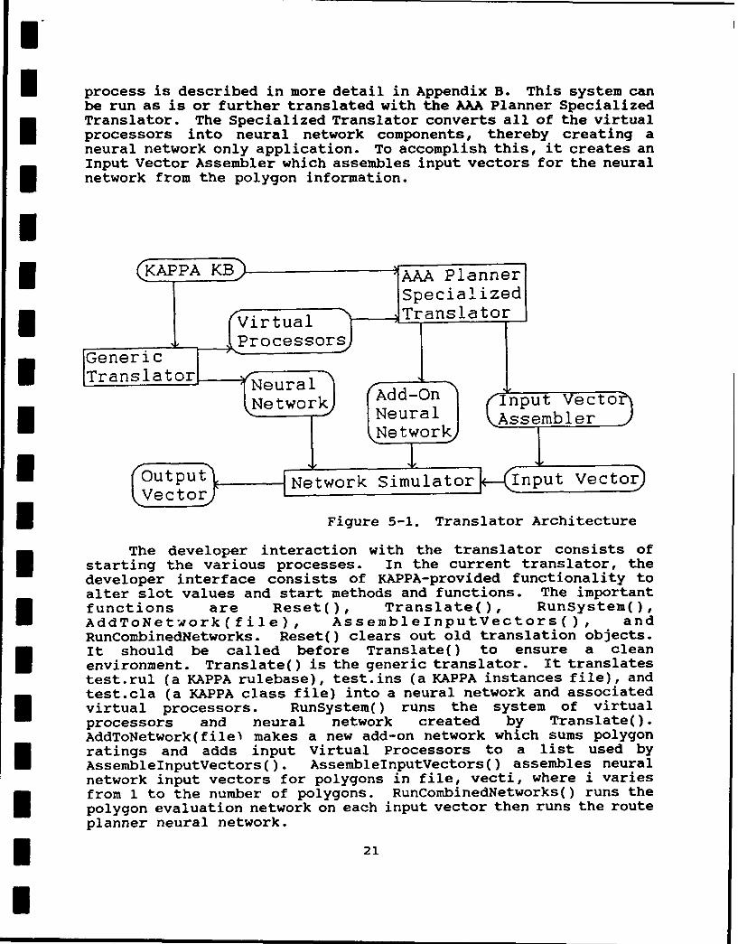
E process is described in more detail in Appendix B. This system canbe run as is or further translated with the AAA Planner SpecializedTranslator. The Specialized Translator converts all of the virtualprocessors into neural network components, thereby creating aneural network only application. To accomplish this, it creates anInput Vector Assembler which assembles input vectors for the neuralnetwork from the polygon information.
II (KAPPA KB AAA P l anner I
|~Specialized
I Figurel 5-Translator
Thedvelo e ineton it hetra nslaorcnsisso
V~irtuaetwork
starting the various processes. In the current translator, the
developer interface consists of KAPPA-provided functionality toalter slot values and start methods and functions. The importantfunctions are Reset(), Translate(), RunSystem,
AddToNetwork(file), AssemblelnputVectors(, andRunCombinedlNetworks. Reset() clears out old translation objects.
It should be called before Translate() to ensure a cleanenvironment. Translate() is the generic translator. It translatestest.rul (a KAPPA rulebase), tset.ins (a KAPPA instances file), andtest.cla (a KAPPA class file) into a neural network and associatedvirtual poces a ndyst ehd runs the system of virtual
functioessrs. Reo rnlt ,RunSystem
processors and neural network created by Translate().AddToNetwork(file% makes a new add-on network which sums polygon
I ratings and adds input Virtual Processors to a list used byAssembleInputVectors( . AssemblelnputVectors() assembles neuralnetwork input vectors for polygons in file, vecti, where i variesnvfrom 1 to the number of polygons. RunCombinedNetworks() runs thepolygon evaluation network on each input vector then runs the routeplanner neural network.
* 21
I

I
E 5.4.3 Translator Updating Results
The original translator was a combination of Kappa 1.1 and CE code. The C code was linked into the Kappa executable at compiletime. To bring the translator up to Kappa 1.3, the executable hadto be remade. This occurred without difficulty. Some behaviordifferences were present in the interpretation of some Kappastatements. These led to errors which were tracked down and re-coded to avoid the error.
5.4.4 Translator Performance Results
The performance of the translator is impressive. One hundredpercent of the rules and inferencing was translatable from the rulebase and expert system building tool. Numeric, symbolic, boolean,and object reference slots are all translated. Using the simpleslot translation strategies previously implemented, 60% to 75% ofI all slots in a typical expert system are translated and thereforeeliminated. In the AAA Planner, the remaining untranslated slots(except for those that served as input to or output from the expertsystem) were translated using the additional translation techniquesdescribed above.
The AAA Planner had 34 rules and 19 slots. The translatedI system had no rules and no slots except to store input from or
output to the user. This total translation was made possible bydeveloping translations of the Rating summing and route planning.
U- It appears that most, if not all, knowledge bases aretranslatable. Of the six knowledge bases we have examined andtranslated so far, all would be translated to the above mentionedI_ standards. The knowledge bases included three examined before thestrategies were developed and three after. The great majority ofslots were used exclusively in comparison or assignments involvingexplicit values. Very few functions or other procedural code wasused.
A broad class of problems can be translated using ourI- strategies. For example, recursive rules will translate correctly.Slot types of numeric, symbolic, boolean, and object reference areall translatable. The best increases in speed as a result ofI parallelization come about when an expert system uses a largenumber of rules and/or objects, as in the large number of polygonsin the AAA Planner. The major prerequisites for translation arethat rule ordering is unimportant and that little procedural code(function calls, methods, user interface, etc.) is used. Whilesuch systems can be translated and function correctly, not all ofthe translated system is neurons; virtual processors would also beIm required. To completely eliminate the virtual processors requiresthat few function calls are used and that those be mainly numericcalculations for which a neural approximation is acceptable (as ingraph navigation algorithms or summing polygon factors).
22
I

I
I There are two options when translating an expert system. Oneis to have the target network represent a single copy of the rules.This network must then be applied to each object the rules rangeover. The other is to create a copy for each of the rule setneurons for each object, so the data for each object is examined inparallel. Which choice is exercised depends on the number ofobjects, the number of neurons created, and the target hardware.For example, with the AAA Planner on a serial processor, we chosethe first alternative.
I The number of neurons created by the translation per object isgiven by the following formula, number of neurons per object = K *number of rules, where K is a constant which depends upon rulecomplexity. K is generally a number between 10 and 25. For theAAA Planner, 31 rules became 666 neurons per object leading to avalue for K of about 21, which corresponds to the fact that therules were relatively complex. Optimizations performed on thenetwork could reduce the number of neurons at least by half.
The translator produces sparsely connected networks. In factthe number of connections is linear with the number of neuronsinstead of proportional to the square of the number of neurons.The AAA Planner translated into 666 neurons and 1447 weights and
* biases.
The success of the expert system to neural network translationoffers great potential benefits to both the military and privatesector. The importance of expert systems as independentintelligent entities has already been recognized. The translationand deployment of an expert system in neural network form and on aparallel processor will allow adaptable, fault tolerant behaviorduring unforeseen events and inputs, and permit high speedperformance.
5.5 Phase II Software Architecture
The Phase II Software Architecture was designed to optimizereal-time performance. This was accomplished by maximizing theamount of computation that could be performed ahead of time. Inthe architecture shown below, processes above the dotted line areperformed ahead of time, off-line, and the processes below thedotted line occur in real-time, on-board.
Elevation grid data is processed through a Landformldentification Module, producing terrain polygons which correspondto hills, valleys, and other terrain features. This informationmust be combined with overlay data such as vegetation and soiltypes, to produce the set of polygons and associated informationused by the AAA Planning Expert System. These are put through thetranslator to produce a neural network and input vector, which
23
I

represents the polygon information. On-board the helicopter, theneural network processes the input vector and produces arecommended path in a matter of seconds. During flight, updateinformation can be written into the input vector and the route canbe replanned, again, in a matter of seconds.
Elevation
Landform
Identification
PolyonsTranslatorIPolygons Polygon olygonsOela Combinerm
Polygons.. Off-LineReal-Time....... ..... .....
Vetr Neural Input Vector
Polygon PolygonJInformation
Figure 5-2. Phase II Software Architecture
This system is able to achieve performance impossible evenwith super-computer power by taking advantage of two facts. One isthat the landform polygons do not change even if information aboutthem does. This permits extensive preprocessing. The second isthat inexpensive, specialized neural network processors exist whichoutperform super-computers by two to three orders of magnitude.
Onboard the helicopter, the user of the AAA Planner would addupdated information on any polygon by editing its information,perhaps through a touch sensitive screen. The system could alsoautomatically keep track of which polygon the helicopter iscurrently in through the use of Global Positioning System (GPS)data. This information would be translated and written into the
24

input vector. The network would process this vector, in effectplanning optimum routes to every polygon from the current location.By specifying the desired destination, the optimal route could bedisplayed. An updated optimal route could be calculated anddisplayed every ten seconds or less, depending on the chosenhardware configuration as calculated in the next section.
I 5.6 Phase II Predicted Performance
The smallest terrain features of interest in the AAA problemhave linear dimensions of roughly 1/2 mile or 1/4 square miles ofarea. This is roughly equivalent to 640,000 square meters or 64grid points in a 100-meter grid. The following discussions follow
u rough, order-of-magnitude calculations.
A rule-base of the required complexity for polygon evaluationwould translate into approximately 1000 neurons or less. At mosteach neuron would average three connections, so at most 3000connections would need to be processed per polygon. A 100 mile by100 mile square of interest should contain at most 40,000 polygons.Therefore, at most 120 million connections would need to beprocessed to evaluate each polygon. Route planning requires 15neurons per polygon. Therefore, at most 1.8 million connections(40,000 polygons x 15 neurons per polygon x 3 connections perneuron) would need to be processed for the route planning portionof the network.
I There are several neural network processing options with arange of costs and performances. One option is to use the PCcompatible Loral P-board, built around Digital Signal Processingtechnology. One P-board costing about $4000 today can process 41.3million connections per second. The time to perform the requiredprocessing is then 3.0 seconds. One benefit of the P-board is thatit is a general purpose floating point accelerator board whichcould be used for other purposes. Another benefit is that allhardware required is already commercially available, and droppingin price. Last July (1991) a single P-board was $9000. If furtherprocessing power was required, an additional P-board could bepurchased and used effectively.
On the other side of the price and performance scale is theCNAPS Server by Adaptive solutions, compatible with UNIX Ethernetsystems. At $55,000 it provides processing of 5 billionconnections per second for a processing time of 0.024 seconds. TheCNAPS is also a general purpose accelerator which could performother tasks, although it only uses integer arithmetic.
Intel has developed an analog neural network processing chipcalled the 80170NX which can process 2 billion connections persecond. The chip processes the connections for 64 neurons every 3microseconds. To simultaneously represent the 1000 neurons couldtake as many as 20 chips. Each polygon could be processed every 3
* 25

I micro seconds for a time of 0.12 seconds. The 600,000 neuronsassociated with the path planning portion of the network wouldrequire at most 0.06 seconds for a total time of 0.18 seconds. At$540 per chip, the cost for the chips would be $10,800. Inaddition, some simple A/D and D/A conversion boards would have tobe developed using existing chips, or purchased outright.
Another alternative is to use a single 8017ONX chip andperform the calculations of each of the 20 chips in the aboveoption, in turn. The software driving the hardware would be morecomplex, the memory requirements would be greater, and thespecialized hardware would have to be faster. But the total costof the hardware would be less. To process the polygons would take20 times as long, 2.4 seconds for all of them. The time to processthe route planning neurons would still be 0.06 seconds as before,leading to a total time of 2.5 seconds.
The advantages of using either 8017ONX approach is that thechip has spare processing power that we are not using. Theprocessing time is independent of the number of connections perneuron if that number remains small. For example, if instead ofthree connections per neuron, we used 30 connections, theprocessing time with the same hardware would be nearly identical.This situation might develop if we introduced neural networktraining which increased the strength of previously zero-valuedconnections.
The translation algorithms can be easily changed to usedifferent types of neurons. This allows us to delay the choice ofhardware until late in the projects, if desired. Actually, all ofthe hardware options described above use real-valued, sigmoidfunction neurons, so no alteration of the translation would benecessary. Translation changes would only be required to takeadvantage of some as-yet-unknown option. If the final hardwarechoice required specialized hardware development, more time wouldbe required.
I
* 26

6.0 TECHNICAL FEASIBILITY
Assuming that terrain polygons are available, the use of anintelligent neural network to process them has been shown to befeasible in Phase I. To determine the practicality requireslooking at costs. Since it is impossible to guess the costs of
hardware two years from now when the system is fielded, we will usetoday's hardware costs. It should be kept in mind that hardwarecosts are still dropping rapidly.
The Loral P-board option requires the $4000 P-board andapproximately $2000 for a portable 486 machine. The total persystem hardware cost is then $6000.
The 20 8017ONX chip option requires $10,800 for the chips.The entire hardware requirements, including the portable 486machine, could be produced for roughly $15,000.
The single 80170NX chip option requires a single $540 80170NX.The entire hardware requirements, including the portable 486machine and chip interface hardware, could be produced for roughly$6000.
One requirement for the final Phase II system which was nottested in Phase I was the conversion of the elevation grid datainto terrain polygons. This was to avoid duplication of effort.We would use techniques developed in the other effort for our PhaseII project, or develop our own techniques. One task which could beperformed by a neural network is to group areas by curvature.Areas of positive curvature form valleys and ravines, while areasof negative curvature form hills and ridges. Curvature can beeasily calculated at each grid point based on the data of thesurrounding points. Smoothing with surrounding curvature valuescould be employed to prevent small bumps and depressions frombecoming their own polygons. If these calculations are performedby a neural network, edge detection is simplified for the polygonsby having a neural layer identify points with areas of oppositecurvature on either side.
I
* 27
7.0 FUTURE RESEARCH AND DEVELOPMENT
There is an enormous amount of both research and developmentthat remains to be performed. Phase I has laid a firm foundationby proving that the translation of the AAA Planner from an expertsystem to a neural network is possible. The AAA Planner and itsassociated neural network must be further developed to takeadvantage of this opportunity. Research should be performed toallow even greater advantage of that translation.
I 7.1 Future Development
Future development includes work on the AAA TDA andimprovements to the translator.
7.1.1 Helicopter Avenues of Approach TDA Development
I In Phase II, the complete AAA Planner using neural networkhardware will be implemented, tested, installed and field-testedon-board a helicopter. A major part of this development will be onthe originating expert system. Domain experts must be identified,interviewed and knowledge engineered. These experts will likelyconsist of personnel from Fort Rucker, Alabama. Most importantly,examples of helicopter path planning must be acquired. Ifpossible, watching the process in an actual tactical setting wouldbe ideal. The Phase I prototype was based on simplified knowledge.The Phase II system must be based on a much more accurate andcomprehensive representation of the AAA planning knowledge.
The Phase I prototype assumed that terrain polygons hadalready been identified. An automatic way of converting theelevation grid data into terrain polygons must be developed. Thismay be provided by another SBIR project or may be developed as partof the Phase II effort. One approach, based on curvature, isdescribed in Appendix A.
The Phase I prototype's interface was the minimal required todemonstrate the application. The final system's user interfacemust meet the rigid requirements of a high-pressure, tacticalenvironment. Where the Phase II interface development was anegligible fraction of the development effort, the Phase IIinterface work will be a considerable portion of the project.Touch-sensitive screens should be investigated as one possibleinput/output device, especially for specifying current position ordesired target area. The interface will go through severaliterations in simulated cockpits with helicopter crews to ensurethat it enhances, not detracts from, their abilities.
The Phase I effort could not include specialized neuralnetwork hardware. Several options have already been identified.These and others will be investigated in Phase II. Because oftheir low cost and the flexibility of the translator, several
28

different neural network processors may be acquired and evaluatedin detail. The translator is an inherent component of the Phase IIeffort. Therefore, development will proceed on it in parallel withthe AAA Planner, as described in the next section. The Phase IIdesign is described in Appendix A.
7.1.2 Improvements to the Translator
To improve the network resulting from translation of the AAAPlanner expert system, the translator itself must be improved sothat it is sophisticated, practical, and tunable. Currently, thetranslation process emphasizes the correctness and parallelizationof the final network. The neural network behaves exactly as theexpert system does. This was necessary for a convincing proof ofthe feasibility of translating an expert system. To seize upon thePhase I research, the user should also be able to maximizeadaptability, generalization, and fault-tolerance of the finalneural network. Certainly the size or speed of the network onvarious platforms could also be optimized.
Both binary and real valued neurons with various outputfunctions and various topology types must be allowable targets.Fuzzy Logic Networks must be supported. If a conversion toConjunctive Normal Form (CNF) proves useful it should beimplemented. This would allow a more neural-like network t, pology.A better set of slot conversion strategies should be implemented.Lists can be implemented with a set of neurons corresponding to thepossible members of the list. Assignments to one slot from anotherslot could be handled with a more intelligent analysis.Comparisons between two slots in the antecedent should be supportedinstead of just between a slot and an explicit value. Certainfunctions and methods could be translated into a network framework,including certain classes of user-defined functions and methods.A more generic representation for numbers could be implementedinvolving a binary representation or by making use of inputneurons.
Optimizations on the network can be performed which eliminateneurons and thereby reduce the number of layers. Multivariablerule translation was designed but needs to be implemented. Thetranslation must occur rapidly and should be implemented in ahighly portable language such as C.
Functions normally associated with Knowledge Base ManagementSystems can be performed on the rule-base. These includeoptimizations such as the removal of redundant rules, combiningrelated rules, and checking for correctness, consistency or orderindependence. Optimizations can also be added in the logic networkto neural network translation process. Certain logic networkelements commonly appear together and these can be bettertranslated as a group, instead of individually.
29
7.2 Future Research
Further research into adaptability, fault tolerance,generalization and other optimizations will benefit the AAAplanner. These research ideas are discussed in the followingsections.
I 7.2.1 Adaptability
Research must be performed to determine the best way to makethe neural network easily adaptable. Two options should beinvestigated. The simplest option is to associate another neuralnetwork with the translated neural network. This neural networkshares the translated network's input and output neurons, initiallyadding effectively nothing to the output. The translated network'sweights are static. All training is performed with the associatedI network's weights. The advantage to this approach is that it isstraightforward and flexible, easily allowing multiple networkparadigms. The disadvantage is that extra neurons are required andthe number of extra neurons and their topology must somehow bedecided upon.
The second option is to change the translation process so thatthe resulting network Is more adaptable. Currently, the structureof the network miro)s the structure of the rule base. The weightsare set very hi.,l, 6i-o guarantee logical behavior. For adaptablenetwork behavior, the weights need to be relaxed considerably. Thedegree to whi..h they should be relaxed depends on many factors andshould be somewhat under a user's control. For example, theweights could be relaxed a minimal amount so that correct behavioris always guaranteed. They could be relaxed so that sometimesvalues are produced outside of allowable ranges. In the extremecase, they could be relaxed until values produced fall in incorrectranges, thus producing predictable errors.
An alternative approach for adaptation is to alter thetopology of the network. One strategy is to convert the logicnetwork into Conjunctive Normal Form (CNF). This coild then beconverted into a neural network with a relatively small number oflayers. Such a network would likely be more amenable to adaptationthan the networks which are currently produced.
7.2.2 Fault Tolerance
Research also needs to be performed to allow greater faulttolerance of the produced network. Currently, a broken connectionin the network corresponds to altering a particular expert systemrule for a particular object. Alteration of a rule is certainlybetter than failure of the entire expert system when a wire in itsprocessor breaks. However, this is not as fault tolerant as manyneural networks. Fault tolerance can be achieved in three ways.The first way would be, in hardware, to triple each connection and
I30

divide each weight by three, This would mean that the loss of anyone connection would have no effect, but the loss of a singleneuron would still cause erroneous, but not disastrous, results.If this process is taken a step further, each neuron could betripled; this requires nine times the number of connections but nosingle loss would cause incorrect behavior. The disadvantage is,of course, the extra neurons and connections required. Althoughfurther research is required to determine a more exact number ofextra neurons and connections for more fault tolerant behavior,tripling the current number would seem to be the minimal amountnecessary.
As with adaptation, another solution exists to the problem ofincreasing fault tolerance - change the structure of the networkproduced by the translation. This might entail converting thelogic network to CNF and then completely connecting adjacentlayers. Research would be required to determine proper weights onthe added connections. One solution is to use training to setthose weights.
7.2.3 Generalization
The generalization capabilities of our translated networkshave not been investigated. Currently, the network accepts inputswithin 0.1 of 0, 1, and 0.5, corresponding to true, false, andunknown, and produces outputs in these same allowed ranges.Intermediate values would tend to be interpreted as falling in theclosest allowed range, which may or may not be the bestinterpretation. Research should be performed to take advantage ofvalues outside the allowed ranges. Investigating Fuzzy Logic (FL)would be appropriate, since currently the network implements FL forOrs, Ands, and Nots in the expert system for neural values near 0,0.5, and 1. Additionally, FL systems are becoming common in manyactual hardware controllers.
7.2.4 Neural Structuring
The above three topics (adaptability, fault tolerance, andgeneralization) can all be considered part of a more general topic,which is how to make the translated network behave more like aneural network and less like an expert system. This would also aidthe process of designing a neural network for some task by writingan expert system and translating.
As mentioned previously, one way to make the network moreneurally structured is to convert the logic network to CNF, thentranslate this logic network into a small number of layers. Manyconnections would need to be added to fully connect adjacent layerssince the translation process creates many 0 weights. The weightsof these added connections could be calculated or perhaps set withtraining.
31

In performing the research, two opposing concepts must bebalanced. We must allow for specific neural paradigms for currenttranslation, while staying general to easily take advantage offuture discoveries of new paradigms.
7.2.5 Optimizations
There are optimizations associated with each of the threeprimary software modules in the translator. Type 1 optimizationsare performed on logic network templates during the rules to logicnetwork templates translation. Type 2 optimizations occur duringtemplate instantiation on the instantiated logic networks. Type 3optimizations are performed on the neural networks during the logicnetwork to neural network translation process. The variousoptimization strategies are outlined below.
Type 1 Otimizations
Type 1 optimizations actually may occur on the generic rules,during the translation from rules to logic network process, or onthe resulting logic network. Optimizations can be performed basedon the type of inference desired in the final system. For example,there may be different answers to the following questions: Is itimportant to fire all true rules or only true rules whoseantecedent contains slot names on an agenda? Must virtualprocessors only execute once and in the order dictated by the logicor can they also execute at once?
There are various optimizations normally associated withKnowledge Base Management Systems (KBMSs). These include combiningand eliminating rules. Certain gates often appear together. Thesecould be combined into new types of gates which would improve thefinal neural representation. Rules or the logic network could betranslated into Conjunctive Normal Form (CNF) since all logicalsystems have an equivalent CNF representation. This transformationcombined with new types of gates could lead to a network with veryfew layers.
Type 2 Optimizations
Type 2 optimizations are performed during the logic networkinstantiation process and on the instantiated logic networks. Theoptimizations are the same as Type 1 but are only possible afterthe logic network has been instantiated. This would primarilyinclude rules whose antecedent (or consequent) ranges over adifferent set of objects than the consequent (or antecedent).
Type 3 ODtimizations
Type 3 optimizations occur during logic network to neuralnetwork translation and on the resulting generic neural network.These optimizations include eliminating neurons to reduce the
32

number of layers; adding neurons to increase the fault toleranceand robustness of the network; changing network structure orweights for increased adaptability, generalization, speed, orlogical correctness; and increasing the Fuzzy Logic properties ofthe network.
In performing the optimizations there are many considerations.One is that the above mentioned goals are often contradictory. Thetype of neurons must be considered. The target neural paradigm isimportant and several must be supported. Finally, whether a 2- or3-valued logic is being used has a dramatic effect. Whereas mostgates require 4 neurons with a 3-valued logic, only one would berequired for a 2-valued one.
33

m
I 8.0 CONCLUSIONS
The Phase I results absolutely demonstrated the feasibility ofdeveloping a prototype intelligent Tactical Decision Aids (TDA)neural network system through the use of an expert system to neuralnetwork translator. We implemented the prototype solution withexpert system technology. We then completely translated thatsystem to a neural network representation using our automatictranslator. The network's performance was evaluated using testcases and a neural network simulator. Additionally, theperformance of the completed Phase II system was estimated. Thetime to completely plan a route in a 100 mile by 100 mile area wasconservatively estimated to be 3 seconds with a $4000 specializedboard and a 486-based PC. These results clear the way fordevelopment of a complete system in Phase II.
There is an enormous amount of both research and developmentthat remains to be performed. Phase I has laid a firm foundationby proving that the translation of the AAA Planner from an expertsystem to a neural network is possible. The AAA Planner and itsassociated neural network must be further developed to takeadvantage of this opportunity. Research should be performed toallow even greater advantage of that translation.
There are many potential applications of this research. Themost direct application will be for Airborne Avenues of ApproachPlanning. This technology could be applied to many route planningproblems including Avenues of Approach for ground units. Thetechniques used here would benefit any application involving theintelligent evaluation of a large number of items. Examplesinclude threat evaluation and image understanding. Finally, thegeneric translator can be used to allow almost any expert system tobe translated to a neural network and thus receive the combinedbenefits of each technology.
IIIIIIn3I

IAPPENDIX A PHASE II DESIGN
The Phase II Software was designed to optimize real-timeperformance. This was accomplished by maximizing the amount ofcomputation that could be performed ahead of time. In thearchitecture shown below, processes above the dotted line areperformed ahead of time, off-line, and the processes below thedotted line occur in real-time, onboard.
IkGrid
Identification xet
Terrain Sytm TranslatorlI
PolygonsPoy n
Polygonslgon(overlay h ' r
Real-TimeU Output vector--Neural Input Vector
Network
Updated (StartinqPolygon 1PolygonIn rmation
Figure A-I. Phase II Software Architecture
Elevation grid data is processed through a LandformIdentification Module, producing terrain polygons which correspondto hills, valleys, and other terrain features.
The input to the landform identification layer is thegridpoint elevations. Each gridpoint corresponds to one inputneuron. The first layer, curvature calculations, contains a neuronfor each grid point. It receives the elevation of the gridpoint itcorresponds to, and its neighboring gridpoints, and calculates anaverage curvature.
A Smoothing Layer neuron receives, from the previous layer,the calculated curvature from one or a small group of neurons. It
I35

U.I
Il also receives input from other neurons in the Smoothing layer. Itsums these inputs, and outputs the average to its neighbors. Inthis way large areas of same signed curvature develop a momentum ofactivation signals which tend to swamp small areas of oppositecurvature. Two large areas of different curvature cancel eachother at their border, accentuating that border.I
Pol gon Edges
Fedge Detection Layerl
I ISmoothing LayerI I_Curvature Calculations Layerl
I Grid Elevations
I Figure A-2. Landform Identification Neural Network Layers
The smoothed curvature calculations are output to the EdgeDetection Layer. A single Edge Detection Neuron receives thesmoothed curvature results from a small group of adjacent neurons.Edge Detection neurons are activated when their inputs aredifferent in sign so that neurons corresponding to a border betweendifferent areas of curvature are activated. These detected edgesare output to form the terrain polygons.
The terrain polygons must be combined with overlay data suchas vegetation, soil types, etc. to produce the set of polygons andassociated information used by the AAA Planning Expert System.This combination is best performed by a GIS as shown in Figure A-3.
During the Phase II effort, SHAI will develop the AAA PlanningExpert System as shown in Figure A-4. This knowledge base will bealterable by Army personnel, if required. This knowledge base willbe translated initially into a template Neural Network. Thistemplate can be instantiated for each polygon or run on eachpolygon separately.
The altered terrain polygons and the neural network templateare put through a second translator to produce a neural network andinput vector, which represents the polygon information, as shown in
36

IFigure A-5. The network can be broken into the network whichevaluates each polygon and the network which plans the route.
I erraionsI ~o iPolygon <P olygonsFoverlay Comb iner
IPolygons GeographicInformationSystem
L GIS Hardware]
Figure A-3. Polygon Combiner
__ r , TemplateAA P__IT__
I Expert System Networ
US Army
I- Figure A-4. AAA Planning Expert System Development
Neura I
Route PlanningNeural Network
* Route)
Figure A-5. Expert System to Neural Network Translation
37
I I i m | i
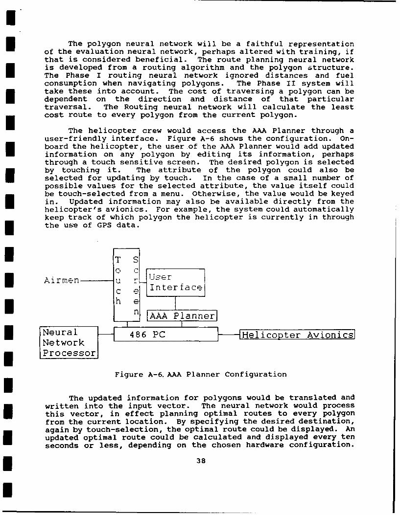
The polygon neural network will be a faithful representation
of the evaluation neural network, perhaps altered with training, ifthat is considered beneficial. The route planning neural networkis developed from a routing algorithm and the polygon 6tructure.The Phase I routing neural network ignored distances and fuelconsumption when navigating polygons. The Phase II system willtake these into account. The cost of traversing a polygon can bedependent on the direction and distance of that particulartraversal. The Routing neural network will calculate the leastcost route to every polygon from the current polygon.
The helicopter crew would access the AAA Planner through auser-friendly interface. Figure A-6 shows the configuration. On-board the helicopter, the user of the AAA Planner would add updatedinformation on any polygon by editing its information, perhapsthrough a touch sensitive screen. The desired polygon is selectedby touching it. The attribute of the polygon could also beselected for updating by touch. In the case of a small number ofpossible values for the selected attribute, the value itself couldbe touch-selected from a menu. Otherwise, the value would be keyedin. Updated information may also be available directly from thehelicopter's avionics. For example, the system could automaticallykeep track of which polygon the helicopter is currently in throughthe use of GPS data.
*T S
Airmen u .Userc eInterface
n AAA PlannerlII
P r al .................. Helicopter Avionics
Figure A-6. AAA Planner Configuration
The updated information for polygons would be translated andwritten into the input vector. The neural network would processthis vector, in effect planning optimal routes to every polygonfrom the current location. By specifying the desired destination,again by touch-selection, the optimal route could be displayed. Anupdated optimal route could be calculated and displayed every tenseconds or less, depending on the chosen hardware configuration.
38

The system is able to achieve this unprecedented level ofperformance by taking advantage of two facts. One is that thelandform polygons do not change even if information about themdoes. A given polygon will always be the same shape, be in thesame location, and have the same neighbors. This permitsextensive, off-line preprocessing. The second is that inexpensive,specialized neural network processors exist which outperform evensupercomputers by more than two orders of magnitude.
iIIIIiIIIIIIII 39
I

APPENDIX B COMPLETE TRANSLATION STRATEGIES
B.1 Rule to Logic Network Translation
B.1.1 Logic Network Description
Logic Networks consist of gates, predicates and virtualprocessors. Gates and predicates input and output logical valuesof false, true, and unknown (F, T, and U).
Gates take inputs from other gates or predicates. Each gatehas one output connected to one or more gates or predicates. Thetypes of gates are ThenGate, UnknownGate, AndGate, OrGate,PredicateAssignmentGate, and NotGate. The functions of the gatesare described in the following truth tables in Figure B-1.
TheI ate (1 input) UnknownGate (1 input)
Input Output Input OutputT T T FU U U TF U F F
AndGate (2 inputs) OrGate (2 inputs)
Second Input Second InputT U F T U FOutputs Outputs
F I T T U F F I T T T Tin inrp U U U F rp U T U U
tt F F F F tt F T U F
PredicateAssignmentGate NotGate (1 input)I (any # of + or - inputs)
Negative Input Input OutputT U F T FOutputs U U
P I T UD T T F To nsp U F U USiutt F F U Uiv UD = Undecidede
Figure B-1. Gate Truth Tables
I40

The PredicateAssignmentGate actually has a number of inputsdivided into two sets - positive and negative inputs. If anypositive inp '. is true then the gate outputs true, if any negativeinput is trie, the gate outputs a false. If both a positive andnegative input are "on", then the output is undefined. Thetranslation is such that this never occurs.
Predicates come in three classes. An input predicate's valueis set by a virtual processor. Trigger predicates and hiddenpredicates behave identically to each other. The output of apredicate of either type is the same as its input. The value of atrigger predicate is monitored by a virtual processor. When thatpredicate's value is True, the virtual processor monitoring itexecutes.
Virtual Processors can read and set predicates' output. Theyconsist of procedural statements and user defined methods andfunctions. Execution begins when an associated (trigger) predicateis true. The final statements set input predicates.
The logic network can be simulated in the following way:
- Initialize all predicates to unknown.- Loop through the following actions until no virtual
processors execute.
Simulate the network consisting of theinterconnected predicates and gates starting withthe input predicates and working upward toward thetrigger predicates.For each trigger predicate which is true, executethe associated virtual processor.
* The graphical logic network representations of typical rulesare given in the following figures. Predicates are represented bycircles, gates are labeled rectangles, and virtual processors areelongated hexagons. Actual inputs to gates are indicated by solidlines, virtual connections are indicated by dashed lines.
Simple Antecedent
The logic network representation of a simple antecedent of arule is given below. This representation corresponds to anantecedent which contains untranslatable items such as functioncalls or input/output slots. A typical example is the antecedent,If Ravine?(p:Depth,p:Width).
The primary element of this logic network is the virtualprocessor. The virtual processor is virtually connected to threepredicates, the trigger predicate (left), the value predicate(above) and the continue predicate (below). All predicate valuesare initially set to unknown. The value of the trigger predicate
41

depends upon the output of the AndGate, whose value is dependentupon an implicit input of true and the output of the UnknownGate.The value of the UnknownGate is obtained from the continuepredicate. If the virtual processor has not executed, the continuepredicate will have a value of unknown. This, when input to theUnknownGate, produces true. This value and the implicit true valueare input to the AndGate to produce a true value, which becomes thevalue of the trigger predicate. The virtual processor examines itstrigger predicate to determine if it should execute. If executionis triggered, the virtual processor sets its value predicate to theresult of the execution, and its continue predicate to true. Thecontinue predicate indicates that the virtual processor hascompleted execution. The next time through the simulation, thetrigger predicate will be false, thus preventing multipleexecutions of the virtual processor. p
1 ,
Figure B-2. Simple Antecedent Logic Network
Simple Consequent
The simple consequent is very similar to the simpleantecedent, with two exceptions. It contains a ThenGate, whoseinput would come from the value predicate of the simple antecedent.It also does not have a value predicate.
E=::!
Figure B-3. Simple Consequent Logic Network
42
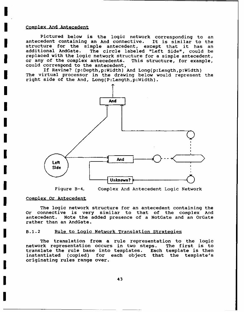
Complex And -Antecedent
Pictured below is the logic network corresponding to anantecedent containing an And connective. It is similar to thestructure for the simple antecedent, except that it has anadditional AndGate. The circle labeled "Left Side", could bereplaced with the logic network structure for a simple antecedent,or any of the complex antecedents. This structure, for example,could correspond to the antecedent,
If Ravine? (p:Depth,p:Width) And Long(p:Length,p:Width)The virtual processor in the drawing below would represent theright side of the And, Long(P:Length,p:Width).
I Ad
Sid9IIII Unk0 --<o >v-
Figure B-4. Complex And Antecedent Logic Network
Comleqx Or Antecedent
The logic network structure for an antecedent containing theOr connective is very similar to that of the complex Andantecedent. Note the added presence of a NotGate and an OrGaterather than an AndGate.
B.1.2 Rule to Logic Network Translation Strategies
The translation from a rule representation to the logicnetwork representation occurs in two steps. The first is totranslate the rule base into templates. Each template is theninstantiated (copied) for each object that the template'soriginating rules range over.
43
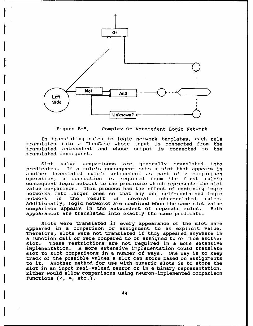
I Od
I (9,
I
Figure B-5. Complex Or Antecedent Logic Network
In translating rules to logic network templates, each ruletranslates into a ThenGate whose input is connected from thetranslated antecedent and whose output is connected to thetranslated consequent.
Slot value comparisons are generally translated intopredicates. If a rule's consequent sets a slot that appears inanother translated rule's antecedent as part of a comparisonoperation, a connection is required from the first rule'sconsequent logic network to the predicate which represents the slotvalue comparison. This process has the effect of combining logicnetworks into larger ones so that any one self-contained logicnetwork is the result of several inter-related rules.Additionally, logic networks are combined when the same slot valuecomparison appears in the antecedent of separate rules. Bothappearances are translated into exactly the same predicate.
Slots were translated if every appearance of the slot nameappeared in a comparison or assignment to an explicit value.Therefore, slots were not translated if they appeared anywhere ina function call or were compared to or assigned to or from anotherslot. These restrictions are not required in a more extensiveimplementation. A more extensive implementation could translateslot to slot comparisons in a number of ways. One way is to keeptrack of the possible values a slot can store based on assignmentsto it. Another method for use with numeric slots is to store theslot in an input real-valued neuron or in a binary representation.Either would allow comparisons using neuron-implemented comparisonfunctions (<, =, etc.).
44
B.2 Logic Network to Neural Network Translation
B.2.1 Neural Network Target Representation
There are two types of elements in a neural network: neuronsand virtual processors. Virtual processors behave identically totheir logic network counterparts, except that they read and set theoutputs of neurons instead of predicates. There are three types ofneurons - input, output and hidden. Output neurons correspond totrigger predicates. A virtual processor is attached to each one.Each input neuron is set by a virtual processor. Output and hiddenneurons behave identically in that each computes its value byperforming its output function on the weighted sum of its inputs.Input neuron outputs are not computed but simply set by virtualprocessors.
Either binary or real-valued neurons could have been used inthe network. Because we are translating a three-valued logic, 2binary neurons are required to represent one truth value. If real-valued neurons are used, either two or one unit can be used. Wedeveloped translation strategies for both neuron types.
In our translator, the neurons are real-valued with a logisticactivation function. Their outputs must be between 0 and 1.Furthermore, the network is designed such that the outputs willfall into three ranges corresponding to F, U, and T, respectively.The three ranges are 0 - 0.1, 0.4 - 0.6, and0.9 - 1.
To simulate the network of neurons and virtual processors thefollowing actions are taken.
- All neurons are initialized to 0.5 output (unknown)- The following two steps are repeated until no virtual
processors execute- Simulate the network- Run all the applicable virtual processors
B.2.2 Logic Network to Neural Network Translation
Real-valued neurons have three ranges defined to correspond tothe three possible truth values. These ranges are defined in termsof constants. The translation strategies from logic network toneural network are also defined in terms of these constants tofacilitate experimentation in future work. The constants aredefined below.
Truth Value RangeFalse 0 -> aUnknown b -> cTrue d ->1
45

In order to facilitate logic network to neural networktranslation it is convenient to keep an ordered relationship amongthe binary sums of truth values. For example, it is convenient forthe sum of any true and unknown value to be less than the sum ofany two true values. This constrains the values of the constantsthat define the ranges. These constraints are shown below.
Constraint Meaning1 + c < 2d true + unknown < true + true2c < 1 + b unknown + unknown < true + unknownc + a < 2b unknown + false < unknown + unknown2a < b false + false < unknown + false
A set of values which we used which satisfy these constraintsare a = .1, b= .4, c = .6, and d = .9.
Each predicate translates into one neuron. Each virtualprocessor that monitors a trigger predicate will instead monitor anassociated neuron. Each virtual processor which sets a predicate,instead sets the corresponding neuron.
Each gate is translated into a group of neurons which computesthe appropriate output. The neural translation for each gate isshown below. The weights and biases are functions of the rangeconstants as well as of two other constants, m and M. Theseconstants are used to force logical values toward 0, 0.5 and 1.They currently are defined to produce large weights and biases (m= 10, M = 50), but should be redefined as smaller numbers tofacilitate adaptation. This would be one subject of futureresearch.
The neural configurations corresponding to the various logicnetwork gates are given below. The circles indicate neurons andthe solid lines, connections. Charts are given showing the biasesand weights for each configuration.
And: Real Neuron Configuration
And Gate TranslationWeights Biases
From To Weight Equation Neuron BiasN5 N2 M NI -m/2N5 N3 M N2 -M(a+b)/2N6 N3 M N3 -M(l+c+2d)/2N6 N4 M N4 -M(a+b)/2N2 N1 m/4N3 N1 mM4 N1 m/4
46

N1
N2 N3 N4
NS NS
Figure B-6. Real And Configuration
Or: Real Neuron Configuration
Or Gate Translationweights Biases
From To Weight Equation Neuron BiasN5 N2 M Ni -m/2N5 N3 M N2 Mcd/N6 N3 M N3 -M(2a+b)/2*-N6 N4 M N4 -M(c+d)/2N2 Ni inN3 NI m/2M4 N1 m
Ni
N2 N3 N4
NS N6
Figure B-. Real Or Configuration
47
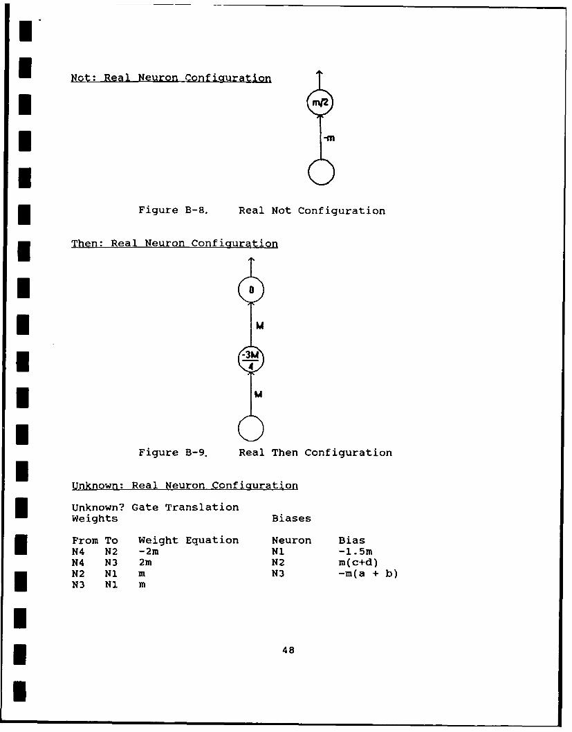
m
Not: Real Neuron Configuration
Figure B-8. Real Not Configuration
i Then: Real Neuron Configuration
*0*M
U 4>* M
Figure B-9. Real Then Configuration
Unknown: Real Neuron Configuration
n Unknown? Gate TranslationWeights Biases
From To Weight Equation Neuron BiasN4 N2 -2m N1 -1.5mN4 N3 2m N2 m(c+d)N2 N1 m N3 -m(a + b)N3 N1 m
in 48
I

I
* NiI
*N2 NI
N4
Figure B-10. Real Unknown Configuration
The above weights and biases assume the logistic activationfunction, O(s,t) = 1/(l + exp(-(s + t))), where s = weighted sum ofthe neuron's inputs and t = threshold, or bias, a constant adjustedduring learning. If a different activation function were used, theweights of the translated system would need to change, but thetranslation concepts would be tlie same.
Translation strategies were alsodeveloped for binary neurons.With binary neurons, two neurons are required to represent one
I predicate. One neuron represents Known/Unknown the otherrepresents True/False. The allowed values for a set of two neuronsis shown below.
I T/F K/U1 1 True0 1 False0 0 Unknown1 0 Unallowed
The advantage of using binary neurons over real-valued ones isthat binary neurons are faster than real-valued (integer vs real-number arithmetic) especially with feedback connections. Thedisadvantage is that with this scheme of values, the network couldbe harder to train than the real-valued counterpart.
II
nI 49
I
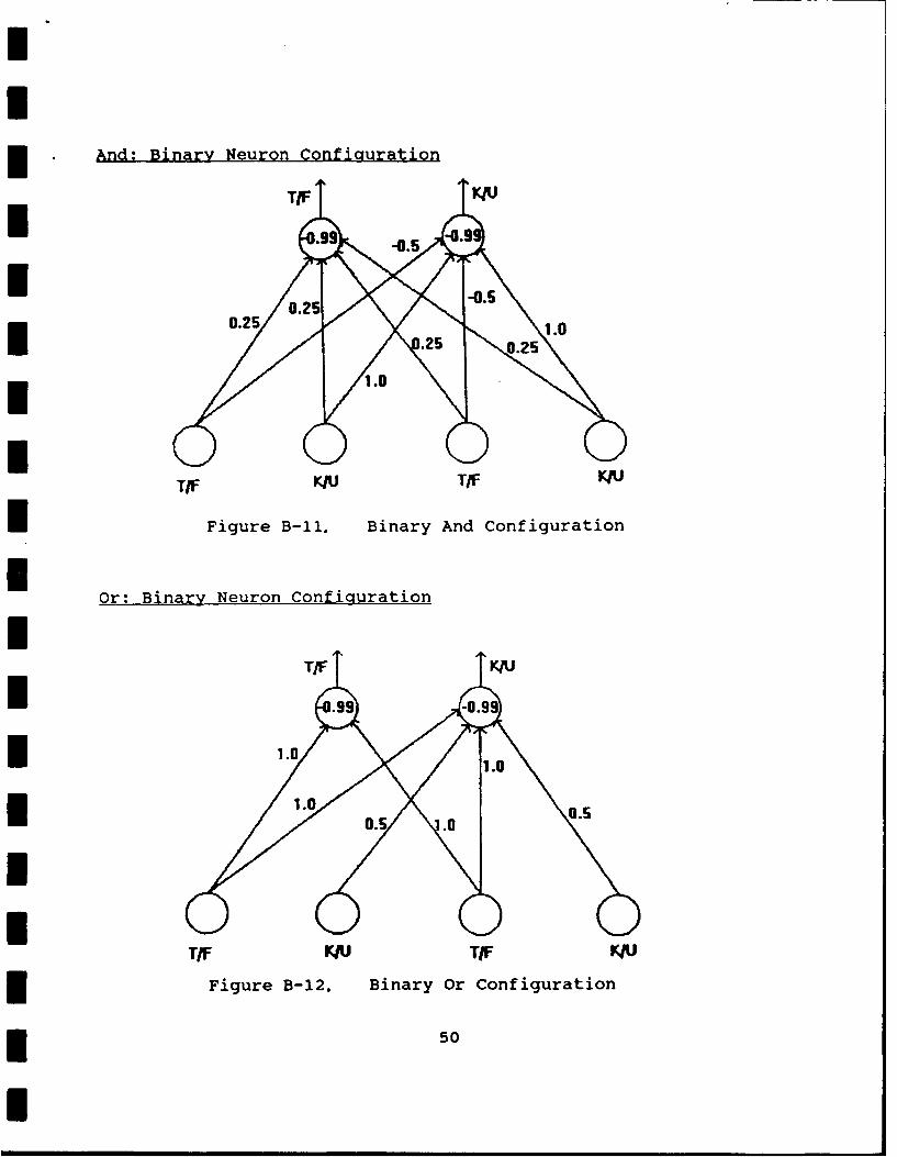
I .And: Binary Neuron Configuration
TIF K T/F J
IFigure B-il, Binary And Configuration
Or: Binary Neuron configuration
II A
TIF KIU TIF U
Figure B-12. Binary Or Configuration
* 50

Not: Binary Neuron Configuration
-.5 -0.5
-1.0 1.0 1.0.
I0
IFigure B-13. Binary Not Configuration
Then: Binary Neuron Configuration
1TIF J
-0.5 -0.5
I i.O1.0
0ITIF A
Figure B-14, Binary Then Configuration
* 51

U
B.3 Additional Translation Strategies
B.3.1 Rating Summation
The first step is to identify virtual processors that sum apolygon's rating. These are always associated with a ruleconsequent. Next, we identify the value which is added to (orsubtracted from) the Rating. The translator then finds the neuronwhich triggers activation of the virtual processor as shown infigure B-15. That triggering association is broken and aconnection from the trigger neuron is created. That connection isweighted with the value that would be added to the rating andattached to a summing neuron for each polygon as shown in FigureB-16.
I Tagger\Neuron ------ pRating Rating - 3 >
I /-N. __"
Trigger /Neurn) ..-------- p Rating= DRating + 5
Figure B-15. Before Translation
(u mingNeur n
+5N5euron "/ p atin=o Rating-3
Trigger ''
I Neuron
Figure B-16. After Translation
52
I

The summing Neuron simply sums its input and passes the ratingon to the next stage.
B.3.2 Route Planning
The overall goal of the route planning translation is to plana route through a series of polygons using a neural network. Thisnetwork finds a minimum cost route to all polygons from a startingpolygon. The input to the translation process is a list ofpolygons. With each polygon is a list of the adjacent ones. Theoutput is a neural network which calculates a minimum cost route.The inputs to the created neural network are the cost to traversethe polygon and the polygon in which to start the route. Theoutput is the minimum cost route to all polygons from the startingone.
The translation is a two-step process. The first step is toconvert the network of polygons (each polygon is 'attached' to itsneighbors) to a network of gates. Each polygon maps to a certainset of gates based on the number of neighbors it has. A gate hasmultiple inputs and one output which computes some simple functionof the inputs. The second step is to convert the gate network to
a network of neurons. Each gate maps to a set of neurons whichperform its function. Those two steps are described in more detailbelow.
In the first step, each polygon is converted into a network ofthe following components:
1 Starting Polygon (Network Input) node which can be set to 0(this is the starting polygon) or infinity (this is not thestarting polygon).
1 Local Cost (Network Input) node which can be any positivenumber. This input gives the cost to traverse the polygon.
N Which Neighbor (Network Output) nodes whose names are thename of the corresponding polygon concatenated with the namesof the corresponding neighbor polygons. N is the number ofneighbors. This network output gives which neighbor theminimum path comes from.
N Input Neighbor Cost lines (N is different for each polygon)corresponding to the polygon's N Neighbors. These connectionsoriginate with the networks of the neighboring polygons.
1 Min Gate with N+1 inputs. The inputs are the N InputNeighbor Cost lines and the Starting Polygon Network InputNode. A Min Gate outputs the minimum value of any of itsinputs.
N SameGates. Each gate has two inputs, an Input Neighbor cost
53

line and the Min Gate output. The output of each SameGate is
connected to a Which Neighbor node. A SameGate outputs a 0if its two inputs are the same and a positive value if theyare different.
1 Sum Gate - 2 inputs, the output of the Mir Gate and theLocal Cost Node. The output of the Sum Gatc % used as anInput Neighbor cost line for neighborin 9olygons andrepresents the minimum cost for the minimum path from thestarting polygon to this one.
Figure B-17 is an example for one polygon.
IOutput Cost Poly 1 Poly 2 Poly 3
I is best is best is best
ISum Gatel Same Same SamellGate lGate Gatel
Extra
Cost
IStarting Cost 1 Cost 2 Cost 3Polygon From Adjacent Polygons (N=3)
I All costs initialized to infinity.
Figure B-17. Route Planner Fragment for One Polygon
The second step is the translation from the gate network to aneural network. A Network Output Node can be translated to asingle output neuron. A Network Input node can be translated intoan input neuron. A Min Gate must first be converted into a networkof binary min gates. The translation of Binary Min Gates, SameGates, and Sum Gates is given by the following figures.
I
I 54

OutputOutput
E . 0.S Output
Input Input
,nput 1 Input 2Input 1 Input 2 1 2
Figure B-18. Figure B-19. Figure B-20.
Binary Min Gate Same Gate Sum Gate
U5

APPENDIX C PROTOTYPE DESCRIPTION
This section will describe the prototype as a logical orderingof events.
A rule-base was created which rates polygons as to theirdesirability for helicopter traversal based on information aboutthat polygon. This rule-base could be easily changed and thesucceeding steps repeated.
I The rule-base was translated into a network of neurons andvirtual processors using the generic translation strategies. Thatnetwork was then translated into a network of only neurons throughthe use of specialized strategies.
The route planning neural network was created by first readingthe polygon information from a file. A connectivity map wasautomatically generated which specifies which polygons border eachother. That connectivity map is translated into a neural network
I which finds the least cost route from an input vector of costs.
After the polygons are read in, they can be displayed in theprototype as in Figure C-1.
II
Figure C-l. Polygon Map Display
56

The polygon information then goes through a preprocessingstep. To calculate Linearity, the points of a polygon are treatedas random and the covariance between the X and Y coordinates of thepoints is calculated. Some adjustments must be made to allow forthe average slope of the polygon's points in the X-Y plane. Todetermine Length, the code calculates every possible distancebetween the points of the polygon and uses the maximum. The pointswhich give that maximum distance are saved for use by the areacalculation method.
At this point the polygon's information might be edited tocorrect or update the original information which was read in. Inpreparation to run the network, the input vector is assembled fromthe polygon's information.
All of the above steps have occurred ahead of time, sometaking significant processing time. The following steps would alloccur at demonstration time. Any polygon can be re-edited and onlythat new information is written over the old information in theinput vector. Then the neural network is run. The first stage ofthe network rates the factors associated with each polygon. Thenext stage sums those ratings into a cost. The last stage of thenetwork uses those costs to plan a minimum cost route to everypolygon from the current one. Finally, this route can be displayedas in Figure C-2.
Figure C-2. Route Display
------------------
57--------------
57

APPENDIX D KAPPA KNOWLEDGE BASE
Below is a listing of the prototype AAA Planner's knowledgebase. The knowledge base was implemented in KAPPA and includesrules, methods called in rules, and slots.
***RULE: AAWRule
MakeRule( AAWRule, [plPolygons],Identity (p:AAWCoverage )#= TRUEp:Rating =p:Rating - 10 )
***RULE: AAWNotRule
MakeRule( AAWNotRule, [piPolygons],Identity (p:AAWCoverage )#= FALSEp:Rating =p:Rating + 10 )
***RULE: EGU
MakeRule( EGU, [plPolygons],Identity (p:EnemyGroundUnits )#= TRUEp:Rating =p:Rating - 5 )
***RULE: EQUNot
MakeRule*C EQUNot, [plPolygons],Identity (p:EnemyGroundUnits )#= FALSEp:Rating =p:Rating + 5 )
***RULE: Enemy
HakeRule( Enemy, [plPolygons],Identity (p:Owned )#= Threatp:Rating =p:Rating -5 )
***RULE: Friendly
MakeRule( Friendly, [plPolygons],Identity (p:Owned ) =Friendly,p:Rating =p:Rating + 5 )
***RULE: TrafficableNot
MakeRule( TrafficableNot, CplPolygons],
58

p:Owned #= Enemy AndIdentity ( p:Trafficable ) =FALSE
p:Rating = p:Rating + 2 )
***RULE: Trafficable
MakeRule( Trafficable, [piPolygons],p:Owned 1=Enemy And p:Trafficable #= TRUEp:Rating =p:Rating - 2 )
***RULE: CoveredByDustSnow
MakeRule( CoveredByDustSnow, [pI Polygons),Identity (p:CoveredBy ) =Snow Or p:CoveredBy #=Dust,p:Rating =p:Rating - 2 )
***RULE: CoveredByWater
MakeRule( CoveredByWater, (plPolygons],p:CoveredBy #= Water And Identity ( p:Width )> 50,p:Rating = p:Rating - 4 )
***RULE: CoveredByVegetation
MakeRule( CoveredByVegetation, [pj Polygons],p:CoveredBy #= Vegetation,p:Rating =p:Rating + 1 )
***RULE: Forest
MakeRule( Forest, [plPolygons],Identity Cp:Forest V= Heavy )And p:CoveredBy 1=Snow,p:Rating =p:Rating - 4 )
***RULE: Checkpoints
MakeRule( Checkpoints, (pI Polygons),Identity Cp:CheckPoints )> 0,p:Rating =p:Rating + 1 )
***RULE: ManMade
MakeRule( ManMade, (plPolygons),Identity (p:Man~ade ) =TRUEp:Rating =p:Rating -2 )
59

***RULE: ConstructionDensitySub
MakeRule( ConstructionDensitySub, [p1 Polygons J,Identity (p:ConstructionDensity )#= Suburban,p:Rating =p:Rating - 1 )
***RULE: ConstructionDens ityUrban
MakeRule( ConstructionDensityUrban, [p iPolygons],p:ConstructionDensity #= Urban,p:Rating = p:Rating - 2 )
***RULE: ConstructionDensityMetro
MakeRule( ConstructionDensityMetro, t[I Polygons],p:ConstructionDensity #= Metropolitan,p:Rating = p:Rating - 3 )
***RULE: ConstructionDensistyUnin
MakeRule ( ConstructionDensistyUnin, [pI Polygons],p :ConstructionDensity #= Uninhabited,p:Rating = p:Rating + 2 )
***RULE: VisibilityGood
MakeRule( VisibilityGood, [plPolygons],Identity (p:Visibility )#= Good,p:Rating =p:Pating + 1 )
***RULE: VisibilityPoor
MakeRule( VisibilityPoor, [p[Polygons],p:Visibility #= Poor,p:Rating = p:Rating - 5 )
***RULE: Visibility
HakeRule( Visibility, (pj Polygons],p:Visibility V= Fair,p:Rating = p:Rating - 2 )
***RULE: FFire
60

MakeRule( FFire, (piPolygons],Identity ( p:FriendlyFire )#= Originating or p:FriendlyFire 1=Targeted,
p:Rating = p:Rating - 4 )
***RULE: ObstructionsHigh
MakeRule( OkbstructionsHigh, [(pIPolygons],Identity (p:ObstructionDensity ) =High,p:Rating =p:Rating - 2 )
***RULE: ObstructionsNone
MakeRule( ObstructionsNone, (pJ Polygons],p:ObstructionDensity #= None,p:Rating = p:Rating + 2 )
***RULE: NoGorges
MakeRule( NoGorges, [plPolygons],Identity ( p:AverageDepth )> 50 And Identity (p:Width < 2*p:AverageDepth ) V= TRUE
p:Rating = p:Rating - 6 * p:AverageDepth/p:Width )
***RULE: LinearityPoor
MakeRule( LinearityPoor, [plPolygons],Identity (p:Linearity ) >= 0.92 And p:Linearity < 0.97,p:Rating =p:Rating - 2 )
***RULE: LinearityBad
MakeRule( LinearityBad, [piPolygons],p:Linearity >= 0.97,p:Rating = p:Rating - 5 )
***RULE: AridStream
MakeRule( AridStream, [pj Polygons],Identity (p:ClimateType #=1 Arid And p:CoveredBy #= Water,p:Rating =p:Rating + 2 )
***RULE: GentleDepression
61

U MakeRule( GentleDepression, (piPolygons],Identity ( p:Depression )1= TRUE And Identity ( p:Width > 4
p:AverageDepth ) #= TRUE ,
p:Rating = p:Rating + 1 )
**~RULE: AridDepression
MakeRule( AridDepression, [piPolygons],I p:ClixnateType #= Arid And p:Depression #= TRUE,p:Rating = p:Rating + 1 )
*** CLASS: Polygons
MakeClass( Polygons, Belvoir )
/***********METHOD: DrawPoly ******/
MakeMethod( Polygons, DrawPoly,[1Let [len LengthList( Self:PointsX )
If ( len > 0I Then(MoveTo(
GetNthElem( Self:PointsX, 1 )GetNthElen( Self:PointsY, 1I )
For i [2 lenLineTo(
GetNthElen( Self:PointsX, i )GetNthElem( Self:PointsY, 1 )
LineTo(GetNthElem( Self:PointsX, 1 )
I ); GetNthElem( Self:PointsY, 1 ))
/***********METHOD: CalculateLength *******/
MakeMethod( Polygons, CalculateLength,[1
ClearList( Self:EndPoints )Self :Length = 0;Let [N LengthList( Self:PointsX )
For i [1 N]I Let [S i + +1)For j [S N]
Let [d Distance(
Ie~hlm efPitY GetNthElem( Self:PointsX, 1 )
Gett~th~lem( Self: Pointsj
GetNthEleu( Self :PointsY,
I 62

If ( d > Self :Length)I Then (Self :Length = d;SetValue( Self:EndPoints, i, j)
I /*************METHOD: CalculateArea *******/
MakeMethod( Polygons, CalculateArea, [xslot yslot 1
I Self :Area = 0;Self:PCATopLength = 0;Let [p1 GetNthElen( Self:EndPoints, 1 )
[p2 GetNthElem( Self:EndPoints, 2 )H (In LengthList( Self:xsiot )] p
Le [ (GetNthElei( Self:yslot, pI GetNthElem( Self:xslot, p2 )-GetNthElei( Self:xslot, p1 ) )
Let [Ib GetNthElen( Self:yslot, p1 ) - mnI GetNthElen( Self:xslot, p1 )
For i [p1 l p2 - 1 ))1]H ~Let [xl GetNthElen( Self:xslot, i)[yl GetNthElen( Self:yslot, i )[x2 GetNthElen( Self:xslot,
i + +1 )]I [(y2 GetNthElem( Self :yslot,i+ +1 )
I Self :Area =Self :Area +TrapezoidArea( Self:PCATopLength, xl,
yl, x2, y2, mn, b, Self, PCATopLength
Self:PCATopLength = 0;Self:PCAi = p2;While ((Self:PCAi != p1 )
Let [xl GetNthElen( Self:xslot, Self:PCAi )I [yl GetNthElem( Self :yslot, Self :PCAi )[x2 GetNthElen( Self:xslot,
If ( Self:PCAi < nThen ( Self:PCAi +I +1)Else 1 )]
[y2 GetNthElem( Self:yslot,If ( Self:PCAi < nThen ( Self:PCAi+
63

I +1)Else 1I)
(efAeI Self:Area +TrapezoidArea ( Self: PCATopLength, xl,
PCATopLength );Y1, x2, y2, in, b, Self,
Self:PCAi = Self:PCAi + 1;If ( Self:PCAi>n)Then Self:PCAi = 1;
Self :Area Abs( Self:Area )
I /************METHOD: CallCalculateArea ******/
MakeMethod( Plgn, CallCalculateArea, ,SendMessage( Self, CalculateArea, PointsX, PointsY ))
/***********METHOD: CalculateLinearity ******/
MakeMethod( Polygons, CalculateLinearity, [slotnaineLet [N LengthList( Self:PointsX )]HLet [XBar Average( Sl:ons
I Self:PCLStdX = 0;EnuinList( Self:PointsX, x,
Self :PCLStdX =Self:PCLStdX +I~~ x - XBar )'2 )Self:PCLStdX =
Sqrt( Self:PCLStdX )I Self :PCLStdY = 0;EnuinList( Self:PointsY, y,
Self:PCLStdY =Self:PCLStdY +(y - YBar )A2 )
Self :PCLStdY =Sqrt( Self:PCLStdY )
Self:PCLCovar = 0;I Self:PCLStdXprine = 0;For i (I N]
Let [x GetNthElem( Self:PointsX, i )[y GetNthElem( Self:PointsY, i )U Let Cxpriine XBar + y - YBar + 1.4142
Self:PCLStdY * x -I Self:PCLStdX * y
Self:PCLStdY * XBarI +Self :PCLStdX * YBar)
* 64
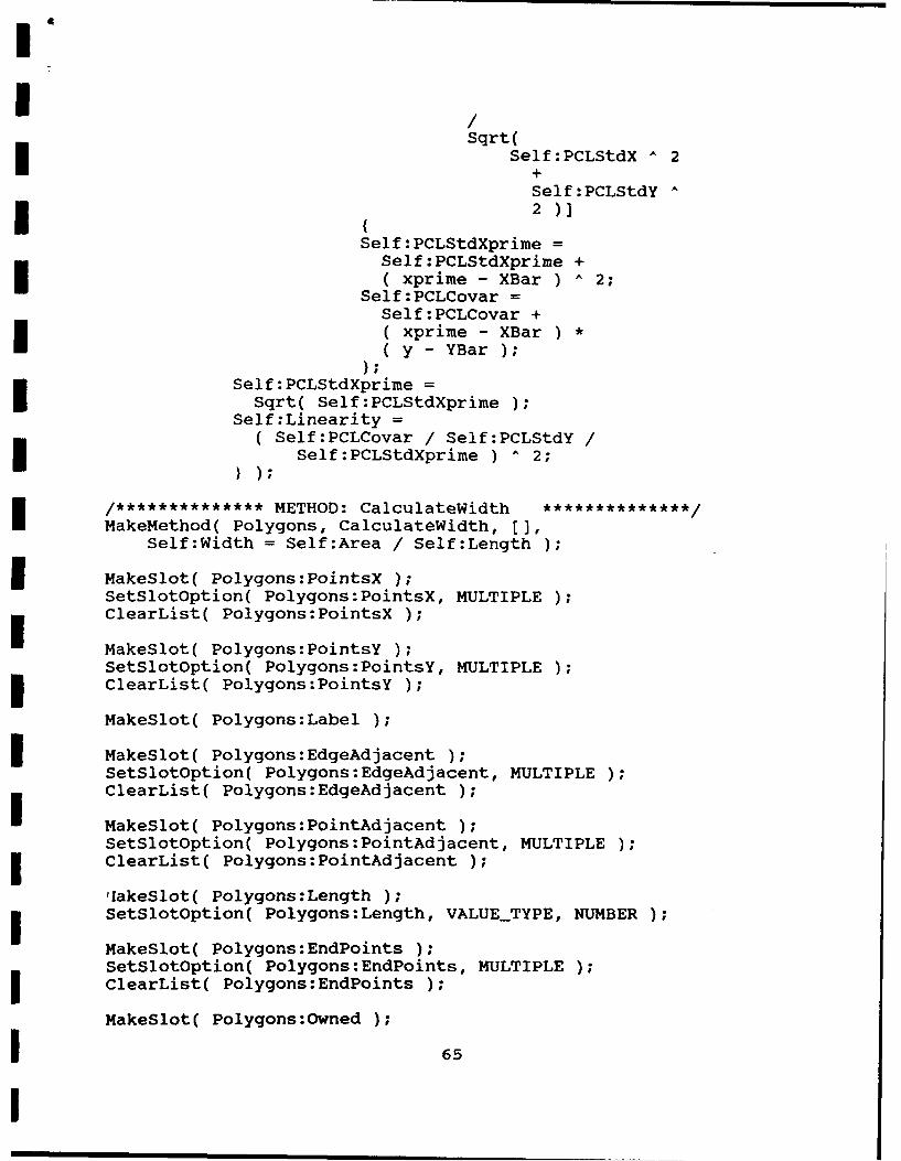
Sqrt(Self:PCLStdX A 2
Self:PCLStdY A
Self :PCLStdXprimeSelf: PCLStdXprime +
Sef( CLoa xprime - XBar ) A 2;Self:PCLCovar =
xprime - XBar )*y -YBar )
Self: PCLStdXprimeI Sqrt( Self:PCLStdXprime )Self :Linearity =
(Self:PCLCovar / Self :PCLStdY/Self:PCLStdXprime ) 2;
/***********METHOD: CalculateWidth ******/MakeMethod( Polygons, CalculateWidth, [],
Self:Width = Self :Area /Self:Length )
I Makeglot( Polygons:PointsX )SetSlotOption( Polygons:PointsX, MULTIPLE )ClearList( Polygons:PointsX )
MakeSlot( Polygons:PointsY )SetSlotoption( Polygons:PointsY, MULTIPLE )ClearList( Polygons:PointsY )
MakeSlot( Polygons:Label );
I MakeSlot( Polygons:EdgeAdjacent )SetSlotOption( Polygons: EdgeAdjacent, MULTIPLE )ClearList( Polygons:EdgeAdjacent )
MakeSlot( Polygons:PointAdjacent )SetSlotOption( Polygons :PointAdjacent, MULTIPLE )ClearList( Polygons:PointAdjacent )
,IakeSlot( Polygons:Length );SetSlotOption( Polygons:Length, VALUE-TYPE, NUMBER )
MakeSlot( Polygons:EndPoints );SetSlotOption( Polygons:EndPoints, MULTIPLE )j ClearList( Polygons:EndPoints )
MakeSlot( Polygons:Owned )
I 65
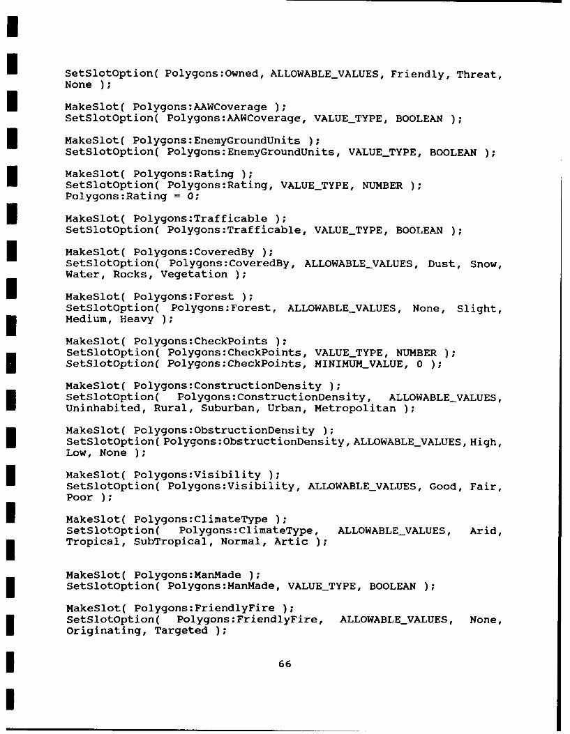
I SetSlotOption( Polygons:Owned, ALLOWABLEVALUES, Friendly, Threat,
I MakeSlot( Polygons:AAWCoverageSetSlotOption( Polygons:AAWCoverage, VALUETYPE, BOOLEAN )
MakeSlot( Polygons:EnemyGroundUnits )SetSlotOption( Polygons:EnemyGroundUnits, VALUETYPE, BOOLEAN )
MakeSlot( Polygons:Rating );SetSlotOption ( Polygons: Rating, VALUE-TYPE, NUMBER )Polygons:Rating = 0;
I MakeSlot( Polygons:Trafficable )SetSlotOption( Polygons:Trafficable, VALUETYPE, BOOLJEAN )
MakeSlot( Polygons:CoveredBy );SetSlotOption( Polygons: CoveredBy, ALLOWABLEVALUES, Dust, Snow,Water, Rocks, Vegetation )
I MakeSlot( Polygons:ForestSetSlotOption( Polygons: Forest, ALLOWABLEVALUES, None, Slight,Medium, Heavy );
MakeSlot( Polygons:CheckPoints )SetSlotoption( Polygons:CheckPoiits, VALUETYPE, NUMBER )I SetSlotOption( Polygons:CheckPoints, MINIMUMVALUE, 0 )
MakeSlot( Polygons:ConstructionDensity );SetSlotoption ( Polygons: ConstructionDensity, ALLOWABLE_VALUES,
Uninhabited, Rural, Suburban, Urban, Metropolitan )
MakeSlot( Polygons :ObstructionDensity );SetSlotOption( Polygons: Obstruct ionDens ity, ALLOWABLEVALUES, High,
MakeSlot( Polygons:Visibility )SetSlotoption( Polygons:Visibility, ALLOWABLEVALUES, Good, Fair,
I MakeSlot( Polygons:ClimateTypeSetSlotoption( Polygons:ClimateType, ALLOWABLEVALUES, Arid,Tropical, SubTropical, Normal, Artic )
MakeSlot( Polygons:ManMade );SetSlotOption( Polygons:ManMade, VALUETYPE, BOOLEAN )
MakeSlot( Polygons:FriendlyFire );SetSlotOption( Polygons:FriendlyFire, ALLOWABLEVALUES, None,
originating, Targeted )
* 66

U MakeSlot( Polygons:AverageDepthSetSlotOption( Polygons:AverageDepth, VALUE_TYPE, NUMBER )SetSlotOption( Polygons:AverageDepth, MINIMUMVALUE, 0 )
MakeSlot( Polygons:Liriearity );SetSlotOption( Polygcsis:Linearity, VALUE_TYPE, NUMBER )
SetSlotOption( Polygons Linearity, IFNEEDED, CalculateLinearity)
MakeSlot( Polygons:Depression );I SetSlotOption( Polygons:Depression, VALUE_TYPE, BOOLEAN )MaeltPoynsCLtX)
MakeSlot( Polygons:PCLStdY
MakeSlot( Polygons:PCL~ovr )
MakeSlot( Polygons:PCLStdXprime )
MakeSlot( Polygons:Width );
MakeSlot( Polygons:CostStack )SetSlotOption( Polygons:CostStack, MULTIPLE )SetSlotOption( Polygons:CostStack, VALUETYPE, NUMBER )ClearList( Polygons:CostStack )
MakeSlot( Polygons:WhoStack );SetSlotOption( Polygons :WhoStack, MULTIPLE )SetSlotOption( Polygons:WhoStack, VALUE_-TYPE, OBJECT )SetSlotOption( Polygons:WhoStack, ALLOWABLECLASSES, Polygons )ClearList( Polygons:WhoStack )
MakeSlot( Polygons:Cost )
MakeSlot( Polygons:Who )
MakeSlot( Polygons:PotentialCost )SetSlotOption( Polygons :PotentialCost, VALUE-TYPE, NUMBER )
MakeSlot( Polygons:PotentialWho );I SetSlotOption( Polygons :PotentialWho, VALUE-TYPE, OBJECT )
SetSlotOptiori( Polygons; Fotentialftp, ALLOWABLE CI*4SSLS, Polygons
MakeSlot( Polvaons:Uodated 1;
SetSlotOntion( Polvczons:Undated., VALU&..TYPE1 BOOLEAN 1
MakeSlot( Polvaons:Area 1;
MakeSlot( Polvaons:PCAToDLenath ;
MakeSlot( Polvaons:PCAi j 6