Embed Size (px)
Citation preview
International Journal of Power Electronics and Drive System (IJPEDS) Vol. 4, No. 3, September 2014, pp. 281~289 ISSN: 2088-8694 281
Journal homepage: http://iaesjournal.com/online/index.php/IJPEDS
DSP-Based Sensorless Speed Control of a Permanent Magnet Synchronous Motor using Sliding Mode Current Observer
Rachid Askour, Badr Bououlid Idrissi Departement of Electromechanical Engineering, Moulay Ismaïl University, Ecole Nationale Supérieure d’Arts et
Métiers, ENSAM-Meknès, Morocco
Article Info ABSTRACT
Article history:
Received Jan 30, 2014 Revised Mar 2, 2014 Accepted Mar 18, 2014
In this paper, experimental results of 3-phase permanent magnet synchronous motor (PMSM) sensorless speed control are presented. To estimate the rotor position, a sliding mode current observer (SMCO) was implemented. This observer estimates the back emfs of the motor in the stationary reference frame using only the measured voltages and currents of the motor. These emfs were utilized to obtain the rotor position. The speed of the motor was calculated by differentiating the rotor position angle. The stability of the proposed SMCO was verified using Lyapunov method to determine the observer gain. The saturation function was adopted in order to reduce the chattering phenomenon caused by the SMCO. A vector control method was employed to achieve the sensorless drive system. The control application was developed in C/C++ language and implemented using the Texas Instruments TMS320LF2812 digital signal processor (DSP). This new processor enables intelligent control for motors. We used to test the drive the MCK2812 which is a professional development kit available from Technosoft Company. The theoretical finding is validated with experimental results that show the effectiveness of the real-time implementation.
Keyword:
DSP real implementation Field oriented speed control PMSM sensorless drive Sliding mode current observer
Copyright © 2014 Institute of Advanced Engineering and Science. All rights reserved.
Corresponding Author:
Rachid Askour, Departement of Electromechanical Engineering, Ecole Nationale Supérieure d’Arts et Métiers (ENSAM), Marjane II, BP 15290, Al-Mansour, Meknès, Morocco Email: [email protected]
1. INTRODUCTION
The PMSM is a good candidate for high performance motion control applications because of its high torque to inertia ratio, high power density and high efficiency. A high performance PMSM drive is based on vector control and this requires knowledge of the rotor position. Indeed, the stator currents of the PMSM are controlled to generate constant torque using the rotor position signal. Therefore, the rotor position must be obtained by either measurement or estimation. The angle of rotor position can be measured with an optical encoder, a resolver or with hall sensors. It is popular to use an encoder mounted on the shaft - the method produces an accurate rotor position angle. If the rotor position is available at every sampling time of the control algorithm, the speed of the PMSM can be easily calculated by differentiating the rotor position angle. However, using the encoder make the motor expensive and mechanically unreliable. Also, the encoder is sensitive to harsh operating conditions like humidity and vibrations. As a result, it is desirable to eliminate the sensor and to use estimates of the rotor position and speed rather than measurements.
There are several methods to estimate the rotor position of the PMSM. Generally, there are two large categories : methods that are based on the magnetic saliency of the PMSM and methods that estimate the variables of interest using the PMSM model [1]. Magnetic saliency methods use the variation of the motor's inductance between the d and q axes [2]. But these methods are relativity difficult to implement and are less portable from one machine to another. However, they work well at low speeds. The second category
ISSN: 2088-8694
IJPEDS Vol. 4, No. 3, September 2014 : 281 – 289
282
of estimation is based on the PMSM model. Several estimation methods based on linear or non linear observers of the PMSM are presented in the literature [3]-[6]. However, in all cases the implementation is relatively difficult. A special class of estimators is based on the sliding mode control techniques [7][8][9]. Interest in this control approach has emerged due to its robustness against parameter variation effects under dynamic conditions with a minimum of implementation complexity.
In this work, the rotor position was obtained using a sliding mode current observer. This method utilizes the model of the PMSM in the stationary reference frame and estimates the rotor position based on the back emfs [10]. The speed of the motor was calculated by pure differentiator. Because established back emfs are negligible at low speeds, we used Hall sensors informations to start the motor. The saturation function was adopted in order to reduce the chattering phenomenon. The SMCO dynamic performances was experimentally verified in the case of PMSM speed vector control. The paper is organized as follows. Section 2 describes the PMSM sensorless control structure. The mathematical background is presented in Section 3. In this section, the PMSM model, the SMCO dynamic equations and the stability analysis are reviewed. Section 4 deals with the DSP real implementation. An evaluation of the results is presented and some digital implementation aspects are discussed. Figures show the effectiveness of the implementation. 2. PMSM SENSORLESS SPEED CONTROL
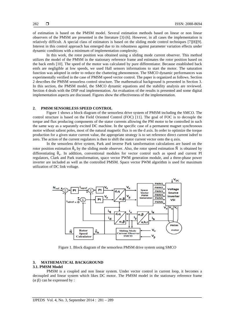
Figure 1 shows a block diagram of the sensorless drive system of PMSM including the SMCO. The control structure is based on the Field Oriented Control (FOC) [11]. The goal of FOC is to decouple the torque and flux producing components of the stator currents allowing the PM motor to be controlled in such the same way as a separately excited DC machine. In the specific case of a permanent magnet synchronous motor without salient poles, most of the natural magnetic flux is on the d axis. In order to optimize the torque production for a given stator current value, the appropriate strategy is to set reference direct current isdref to zero. The action of the current regulators is then to shift the stator current vector onto the q axis.
In the sensorless drive system, Park and inverse Park tansformation calculations are based on the rotor position estimation θ by the sliding mode observer. Also, the rotor speed estimation N is obtained by differentiating θ . In addition, conventional modules for vector control such as speed and current PI regulators, Clark and Park transformation, space vector PWM generation module, and a three-phase power inverter are included as well as the controlled PMSM. Space vector PWM algorithm is used for maximum utilization of DC link voltage.
Figure 1. Block diagram of the sensorless PMSM drive system using SMCO 3. MATHEMATICAL BACKGROUND 3.1. PMSM Model
PMSM is a coupled and non linear system. Under vector control in current loop, it becomes a decoupled and linear system which likes DC motor. The PMSM model in the stationary reference frame (α β can be expressed by :
IJPEDS ISSN: 2088-8694
DSP-Based Sensorless Speed Control of a Permanent Magnet Synchronous Motor … (Rachid Askour)
283
(1)
(2)
Where L is stator self inductance, R is the stator resistance, ( ∝, , ( ∝, and ( ∝, are the phase currents, phase voltages and the back emf in the stationary reference frame (∝ , respectively. The back emf is given by:
. . (3)
Where is the electrical angular velocity, is the flux linkage of permanent magnet and is the electrical rotor position. 3.2. Mathematical Model of SMCO
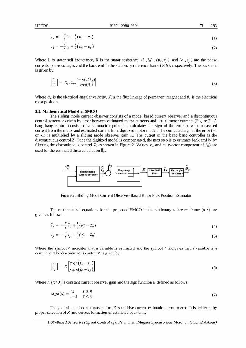
The sliding mode current observer consists of a model based current observer and a discontinuous control generator driven by error between estimated motor currents and actual motor currents (Figure 2). A bang bang control consists of a summation point that calculates the sign of the error between measured current from the motor and estimated current from digitized motor model. The computed sign of the error (+1 or -1) is multiplied by a sliding mode observer gain K. The output of the bang bang controller is the discontinuous control Z. Once the digitized model is compensated, the next step is to estimate back emf e by filtering the discontinuous control Z, as shown in Figure 2. Values e and e (vector component of e ) are used for the estimated theta calculation θ .
Figure 2. Sliding Mode Current Observer-Based Rotor Flux Position Estimator
The mathematical equations for the proposed SMCO in the stationary reference frame (α β are given as follows:
∗ (4)
∗ (5)
Where the symbol ^ indicates that a variable is estimated and the symbol * indicates that a variable is a command. The discontinuous control is given by:
(6)
Where ( >0) is constant current observer gain and the sign function is defined as follows:
1 01 0
(7)
The goal of the discontinuous control is to drive current estimation error to zero. It is achieved by
proper selection of and correct formation of estimated back emf.
ISSN: 2088-8694
IJPEDS Vol. 4, No. 3, September 2014 : 281 – 289
284
In implementation, the above formulations in the continuous domain have to be transfered to the discrete form; therefore, the sliding mode current observer can be formulated by the following difference equation:
1 ∗ (8)
. (9)
Where the matrices and are given by and 1 ; is the current sampling
period and is a 2x2 unity matrix. In addition, the estimated back emf is obtained by filtering the discontinuous control, Z, with a
first order low pass filter (LPF) described by:
(10)
Where the parameter is defined as 2 and represents the cutoff pulsation of the filter. The cutoff frequency of the low pass filter should be designed properly according to the fundamental frequency of the tracked stator currents and to filter out the high-frequency component of the discontinuous control Z. The discrete form of (10) can be expressed by:
1 2 (11)
Finally, the estimated rotor position is derived from the back emf as follows:
(12)
3.3. Roto Speed Calculation
Rotor speed is calculated by differentiating the rotor position angle as follows:
(13)
Where ′ is the speed sampling period.
In addition, the rotor speed is necessary to be filtered out by the low-pass filter in order to reduce the amplifying noise generated by the pure differentiator [12]. The simple first order low-pass filter is used, then the actual rotor speed to be used is the output of the low-pass filter, , given by the following equation:
(14)
Where ′ is the LPF time constant and is the speed cut-off frequency.
3.4. Stability Analysis of the Sliding Mode Current Observer
The sliding plane S is realized on the state variables, i.e., the stator currents, by the switching functions as:
0 (15)
It is necessary to design the Lyapunov function to determine the required condition for the existence
of the sliding mode. Lyapunov function for existence condition of sliding mode is defined as:
IJPEDS ISSN: 2088-8694
DSP-Based Sensorless Speed Control of a Permanent Magnet Synchronous Motor … (Rachid Askour)
285
(16)
Where sliding surfaces are and . and are the error between estimated phase current and actual one in the ∝ and axis respectively. From Lyapunov stability theory, the observer is stable if the function V satisfy V > 0 and < 0, i.e.,
0 (17)
Where,
0 (18)
. ∝ .
∓ 0 0
∓ 0
0
(19)
The part B will be negative definite if the following satisfies:
| | , (20)
As a result, to keep the sliding mode observer stable, the observer gain K should satisfy the
inequality condition:
max | |, (21)
It is noted from the above equation that the observer gain K should be larger than the induced back emf. 3.5. Reducing Chattering Problem
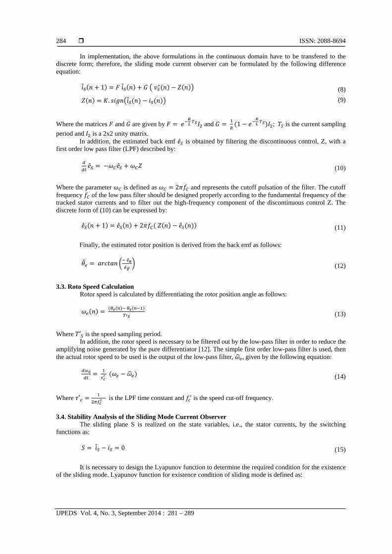
In the implementation of sliding mode control theory in real systems, the main obstacle is an undesirable phenomenon of oscillation with finite frequency and amplitude, which is known as ‘chattering’ [13]. The chattering is harmful because it leads to low control accuracy, high wear of moving mechanical parts, and high heat losses in electrical power circuits. To solve the chattering problem, the sign function can be replaced with its approximation - a continuous form. There are two different approaches possible, i.e. saturation and sigmoid functions (Figure 3). When the amplitude of current error is less than ε, i.e., width of the boundary layer, the discontinuous control Z changes to a saturation or sigmoid function.
Figure 3. Diagram of saturation and sigmoid functions
The saturation function can be described as follows:
, | |
, | | (22)
ISSN: 2088-8694
IJPEDS Vol. 4, No. 3, September 2014 : 281 – 289
286
There exists a great variety of the sigmoid type functions. Some of them are listed below (normalized in such way that their values are between 1):
m s arctan
m s | |
m s /
(23)
In this work, the sign function is replaced by the saturation function.
4. DSP REAL IMPLEMENTATION 4.1. Experimental Setup
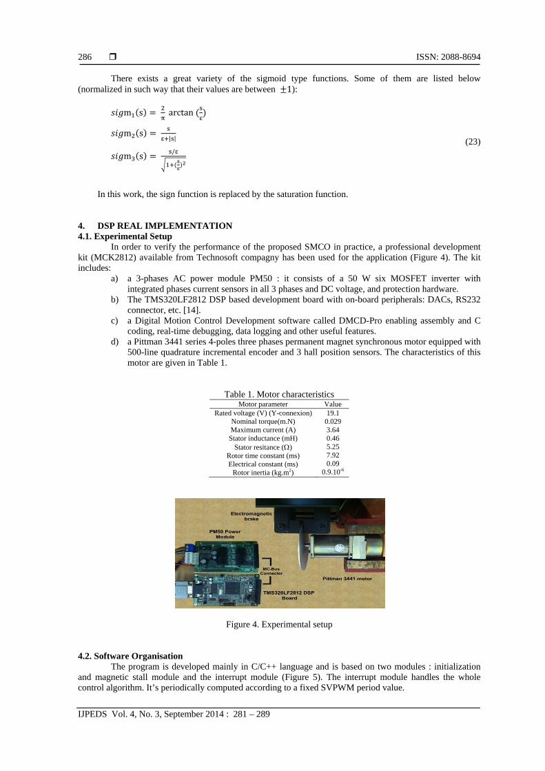
In order to verify the performance of the proposed SMCO in practice, a professional development kit (MCK2812) available from Technosoft compagny has been used for the application (Figure 4). The kit includes:
a) a 3-phases AC power module PM50 : it consists of a 50 W six MOSFET inverter with integrated phases current sensors in all 3 phases and DC voltage, and protection hardware.
b) The TMS320LF2812 DSP based development board with on-board peripherals: DACs, RS232 connector, etc. [14].
c) a Digital Motion Control Development software called DMCD-Pro enabling assembly and C coding, real-time debugging, data logging and other useful features.
d) a Pittman 3441 series 4-poles three phases permanent magnet synchronous motor equipped with 500-line quadrature incremental encoder and 3 hall position sensors. The characteristics of this motor are given in Table 1.
Table 1. Motor characteristics Motor parameter Value
Rated voltage (V) (Y-connexion) 19.1 Nominal torque(m.N) 0.029 Maximum current (A) Stator inductance (mH)
Stator resitance () Rotor time constant (ms) Electrical constant (ms)
Rotor inertia (kg.m2)
3.64 0.46 5.25 7.92 0.09
0.9.10-6
Figure 4. Experimental setup
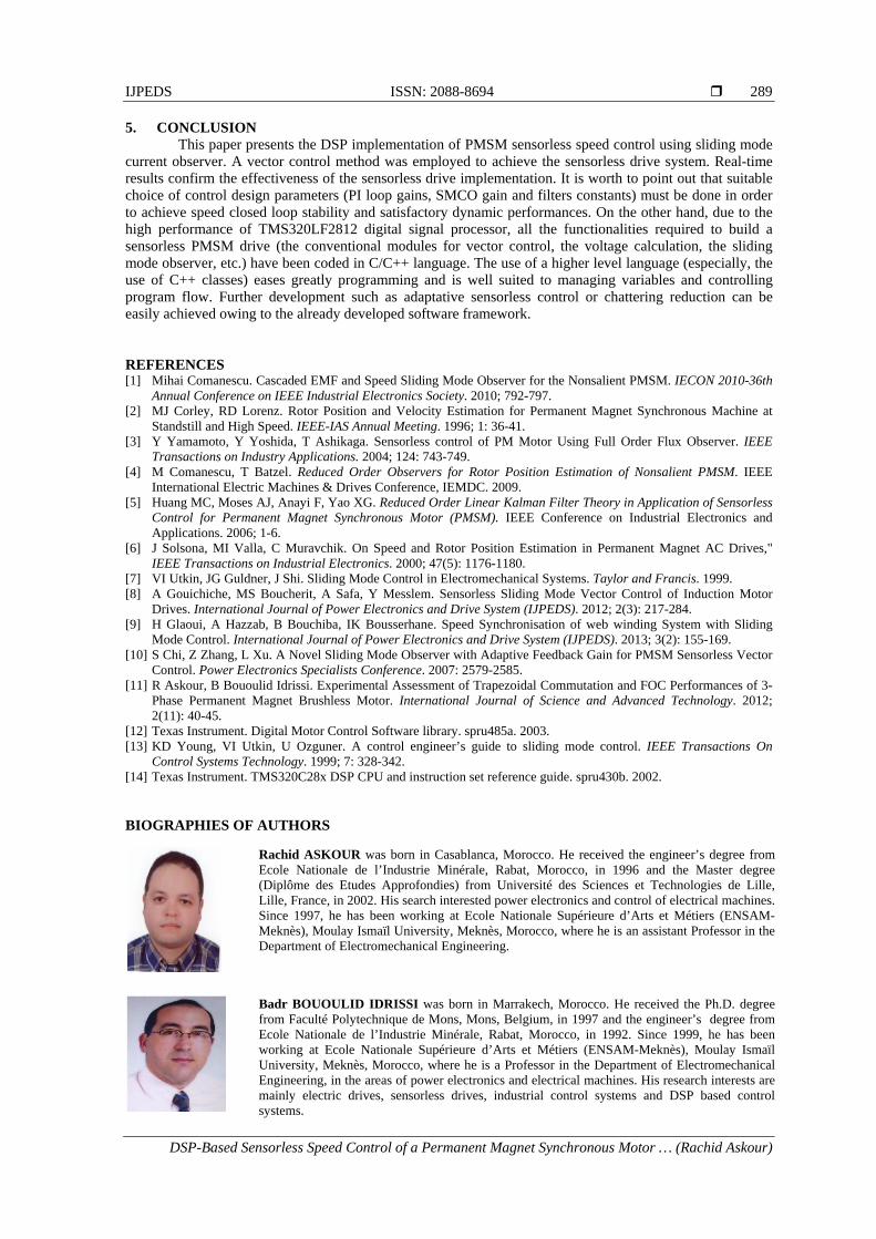
4.2. Software Organisation The program is developed mainly in C/C++ language and is based on two modules : initialization
and magnetic stall module and the interrupt module (Figure 5). The interrupt module handles the whole control algorithm. It’s periodically computed according to a fixed SVPWM period value.
IJPEDS ISSN: 2088-8694
DSP-Based Sensorless Speed Control of a Permanent Magnet Synchronous Motor … (Rachid Askour)
287
The control application use a specific real-time environment, structured on two levels: a) a high priporiy interrupt function triggered every 100 s, mainly for SVPWM generation,
current control and SMCO implementation, b) a lower priority interrupt function triggered every 1 ms, for speed reference and speed control
implementation.
Start
Hardware & Software Initialization
Magnetic stall
Waiting loop
PWM ISRs current & speed loops
execution
Figure 5. General Software Flowchart
The choice of the PWM frequency depends on the motor electrical constant. In this application, the PWM frequency has been set to 20kHz. After the initialization module has completed, a magnetic stall is performed by applying a constant voltage vector to the stator phase: the constant phase currents flowing in the coils create a fixed stator flux. As a consequence, the rotor flux aligns itself naturally onto this stator flux (the rotor is stalled in this position).
Then, a waiting loop starts, and corresponds to an interruptible communication between the DSP monitor and the graphical user interface. If the user sends the start command, the control algorithm start executing. The data-logging allows real-time debugging of the application.
4.3. Real Time Results
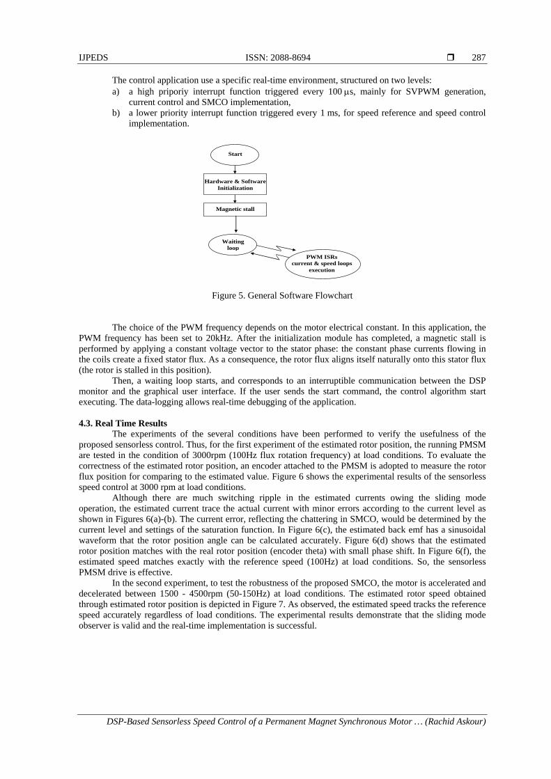
The experiments of the several conditions have been performed to verify the usefulness of the proposed sensorless control. Thus, for the first experiment of the estimated rotor position, the running PMSM are tested in the condition of 3000rpm (100Hz flux rotation frequency) at load conditions. To evaluate the correctness of the estimated rotor position, an encoder attached to the PMSM is adopted to measure the rotor flux position for comparing to the estimated value. Figure 6 shows the experimental results of the sensorless speed control at 3000 rpm at load conditions.
Although there are much switching ripple in the estimated currents owing the sliding mode operation, the estimated current trace the actual current with minor errors according to the current level as shown in Figures 6(a)-(b). The current error, reflecting the chattering in SMCO, would be determined by the current level and settings of the saturation function. In Figure 6(c), the estimated back emf has a sinusoidal waveform that the rotor position angle can be calculated accurately. Figure 6(d) shows that the estimated rotor position matches with the real rotor position (encoder theta) with small phase shift. In Figure 6(f), the estimated speed matches exactly with the reference speed (100Hz) at load conditions. So, the sensorless PMSM drive is effective.
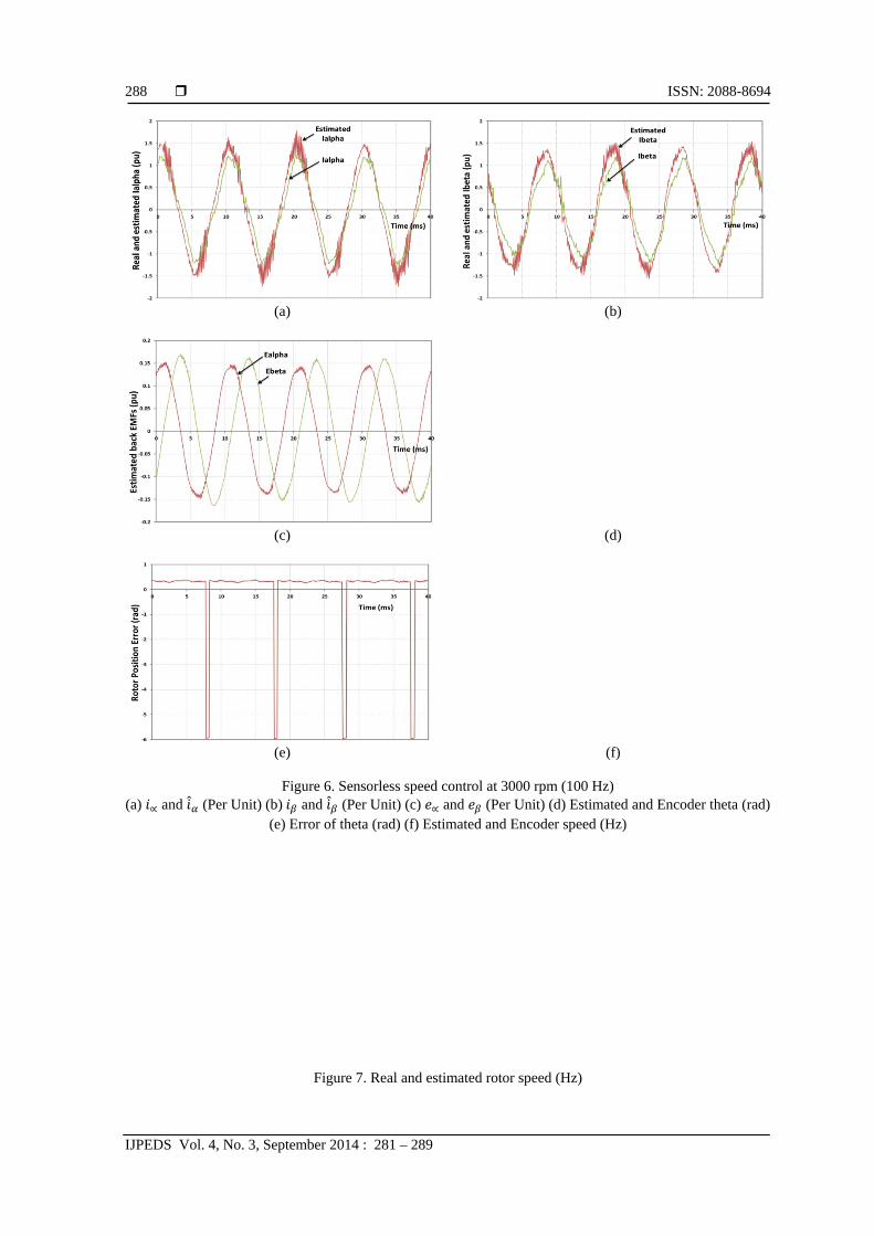
In the second experiment, to test the robustness of the proposed SMCO, the motor is accelerated and decelerated between 1500 - 4500rpm (50-150Hz) at load conditions. The estimated rotor speed obtained through estimated rotor position is depicted in Figure 7. As observed, the estimated speed tracks the reference speed accurately regardless of load conditions. The experimental results demonstrate that the sliding mode observer is valid and the real-time implementation is successful.
ISSN: 2088-8694
IJPEDS Vol. 4, No. 3, September 2014 : 281 – 289
288
(a)
(b)
(c)
(d)
(e)
(f)
Figure 6. Sensorless speed control at 3000 rpm (100 Hz) (a) ∝ and (Per Unit) (b) and (Per Unit) (c) ∝ and (Per Unit) (d) Estimated and Encoder theta (rad)
(e) Error of theta (rad) (f) Estimated and Encoder speed (Hz)
Figure 7. Real and estimated rotor speed (Hz)
IJPEDS ISSN: 2088-8694
DSP-Based Sensorless Speed Control of a Permanent Magnet Synchronous Motor … (Rachid Askour)
289
5. CONCLUSION This paper presents the DSP implementation of PMSM sensorless speed control using sliding mode
current observer. A vector control method was employed to achieve the sensorless drive system. Real-time results confirm the effectiveness of the sensorless drive implementation. It is worth to point out that suitable choice of control design parameters (PI loop gains, SMCO gain and filters constants) must be done in order to achieve speed closed loop stability and satisfactory dynamic performances. On the other hand, due to the high performance of TMS320LF2812 digital signal processor, all the functionalities required to build a sensorless PMSM drive (the conventional modules for vector control, the voltage calculation, the sliding mode observer, etc.) have been coded in C/C++ language. The use of a higher level language (especially, the use of C++ classes) eases greatly programming and is well suited to managing variables and controlling program flow. Further development such as adaptative sensorless control or chattering reduction can be easily achieved owing to the already developed software framework. REFERENCES [1] Mihai Comanescu. Cascaded EMF and Speed Sliding Mode Observer for the Nonsalient PMSM. IECON 2010-36th
Annual Conference on IEEE Industrial Electronics Society. 2010; 792-797. [2] MJ Corley, RD Lorenz. Rotor Position and Velocity Estimation for Permanent Magnet Synchronous Machine at
Standstill and High Speed. IEEE-IAS Annual Meeting. 1996; 1: 36-41. [3] Y Yamamoto, Y Yoshida, T Ashikaga. Sensorless control of PM Motor Using Full Order Flux Observer. IEEE
Transactions on Industry Applications. 2004; 124: 743-749. [4] M Comanescu, T Batzel. Reduced Order Observers for Rotor Position Estimation of Nonsalient PMSM. IEEE
International Electric Machines & Drives Conference, IEMDC. 2009. [5] Huang MC, Moses AJ, Anayi F, Yao XG. Reduced Order Linear Kalman Filter Theory in Application of Sensorless
Control for Permanent Magnet Synchronous Motor (PMSM). IEEE Conference on Industrial Electronics and Applications. 2006; 1-6.
[6] J Solsona, MI Valla, C Muravchik. On Speed and Rotor Position Estimation in Permanent Magnet AC Drives," IEEE Transactions on Industrial Electronics. 2000; 47(5): 1176-1180.
[7] VI Utkin, JG Guldner, J Shi. Sliding Mode Control in Electromechanical Systems. Taylor and Francis. 1999. [8] A Gouichiche, MS Boucherit, A Safa, Y Messlem. Sensorless Sliding Mode Vector Control of Induction Motor
Drives. International Journal of Power Electronics and Drive System (IJPEDS). 2012; 2(3): 217-284. [9] H Glaoui, A Hazzab, B Bouchiba, IK Bousserhane. Speed Synchronisation of web winding System with Sliding
Mode Control. International Journal of Power Electronics and Drive System (IJPEDS). 2013; 3(2): 155-169. [10] S Chi, Z Zhang, L Xu. A Novel Sliding Mode Observer with Adaptive Feedback Gain for PMSM Sensorless Vector
Control. Power Electronics Specialists Conference. 2007: 2579-2585. [11] R Askour, B Bououlid Idrissi. Experimental Assessment of Trapezoidal Commutation and FOC Performances of 3-
Phase Permanent Magnet Brushless Motor. International Journal of Science and Advanced Technology. 2012; 2(11): 40-45.
[12] Texas Instrument. Digital Motor Control Software library. spru485a. 2003. [13] KD Young, VI Utkin, U Ozguner. A control engineer’s guide to sliding mode control. IEEE Transactions On
Control Systems Technology. 1999; 7: 328-342. [14] Texas Instrument. TMS320C28x DSP CPU and instruction set reference guide. spru430b. 2002. BIOGRAPHIES OF AUTHORS
Rachid ASKOUR was born in Casablanca, Morocco. He received the engineer’s degree from Ecole Nationale de l’Industrie Minérale, Rabat, Morocco, in 1996 and the Master degree (Diplôme des Etudes Approfondies) from Université des Sciences et Technologies de Lille, Lille, France, in 2002. His search interested power electronics and control of electrical machines. Since 1997, he has been working at Ecole Nationale Supérieure d’Arts et Métiers (ENSAM-Meknès), Moulay Ismaïl University, Meknès, Morocco, where he is an assistant Professor in the Department of Electromechanical Engineering.
Badr BOUOULID IDRISSI was born in Marrakech, Morocco. He received the Ph.D. degree from Faculté Polytechnique de Mons, Mons, Belgium, in 1997 and the engineer’s degree from Ecole Nationale de l’Industrie Minérale, Rabat, Morocco, in 1992. Since 1999, he has been working at Ecole Nationale Supérieure d’Arts et Métiers (ENSAM-Meknès), Moulay Ismaïl University, Meknès, Morocco, where he is a Professor in the Department of Electromechanical Engineering, in the areas of power electronics and electrical machines. His research interests are mainly electric drives, sensorless drives, industrial control systems and DSP based control systems.