Embed Size (px)
Citation preview

DSG ProjectsAmrit Yegeneswaran
10/16/2018
Contents
• Staff
• ProjectsGas Systems
Hall A SOLID Hall B RTPC. SVT, DC, LTCC, HTCC, MVT
Magnet Controls Hall C PLC Hall D Solenoid Hall B Solenoid &Torus
Interlock Systems Hall B SVT, FT, RICH
HDiceDetectors
Hall B RICH, SVTTest Stations
cRIO, VME, PLC, MPOD
• Conclusion
10/30/2018 Projects 2
DSG Staff(Owner/Manager Patrizia)
Tyler Pablo Peter Amanda Brian
Mary Ann Mindy
Marc George
Amrit
10/30/2018 Projects 3
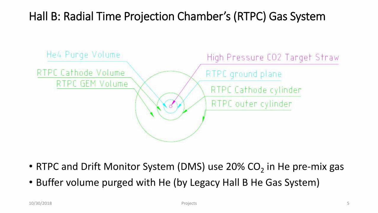
Hall B: Radial Time Projection Chamber’s (RTPC) Gas System
• RTPC and Drift Monitor System (DMS) use 20% CO2 in He pre-mix gas
• Buffer volume purged with He (by Legacy Hall B He Gas System)
10/30/2018 Projects 5
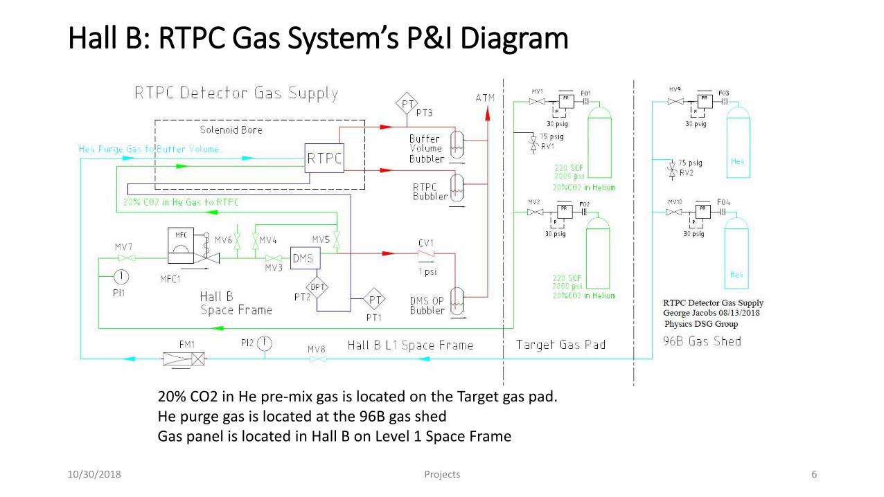
Hall B: RTPC Gas System’s P&I Diagram
10/30/2018 Projects 6
20% CO2 in He pre-mix gas is located on the Target gas pad.He purge gas is located at the 96B gas shedGas panel is located in Hall B on Level 1 Space Frame
Hall B: RTPC Controls and Monitoring System
• GUI, on NI cRio, controls the MFC and monitors signals.
• Signals available on EPICSRTPC Gas Flow: 120 sccmRTPC Absolute Pressure: 760.2 TorrDMS-RTPC Differential Pressure: 0―0.1 TorrBuffer Absolute Pressure: 760.2 TorrBuffer He flow: 10―20 sccm
• Design is complete.
“Sorry to say, I’ve plain run out of things to nag about - it’s perfect!” Sebastian K
• A pressure systems design authority has been assigned.
• Construction is in progress at William and Mary
10/30/2018 Projects 7
Hall A: Gas System for Solid Heavy Gas Cerenkov (HGC)
• Two “Fill & Seal” detectors operating at 1.5 atm (~7 psig) . Atmospheric pressure changes will not affect detector pressure.
During hurricane Michael ΔP~5%
• Detector volume ~10,000 l (~150 Kg of C4F10)“Leak tight” detector critical
C4F10 cost, $260/Kg. (Petrol costs ~$0.80/Kg)
• Potential sources of gas loss Detector volume leakage Loss during recovery operations
10/30/2018 Projects 8
Hall A: Solid HGC Control and Monitoring System
• FunctionsFill gas volumeRemove and store gas from gas volumeMaintain pressure @ 1.5 atm
• MFCs determine detector volume’s leak rate.
• C4F10 recovery for reuse, will use the Hall B distillation systemOnly minor changes required for the connections
• Mobile gas return tank collects gas from detector volumesMobile gas return tank eliminates need of fixed tank and heated gas line
10/30/2018 Projects 9
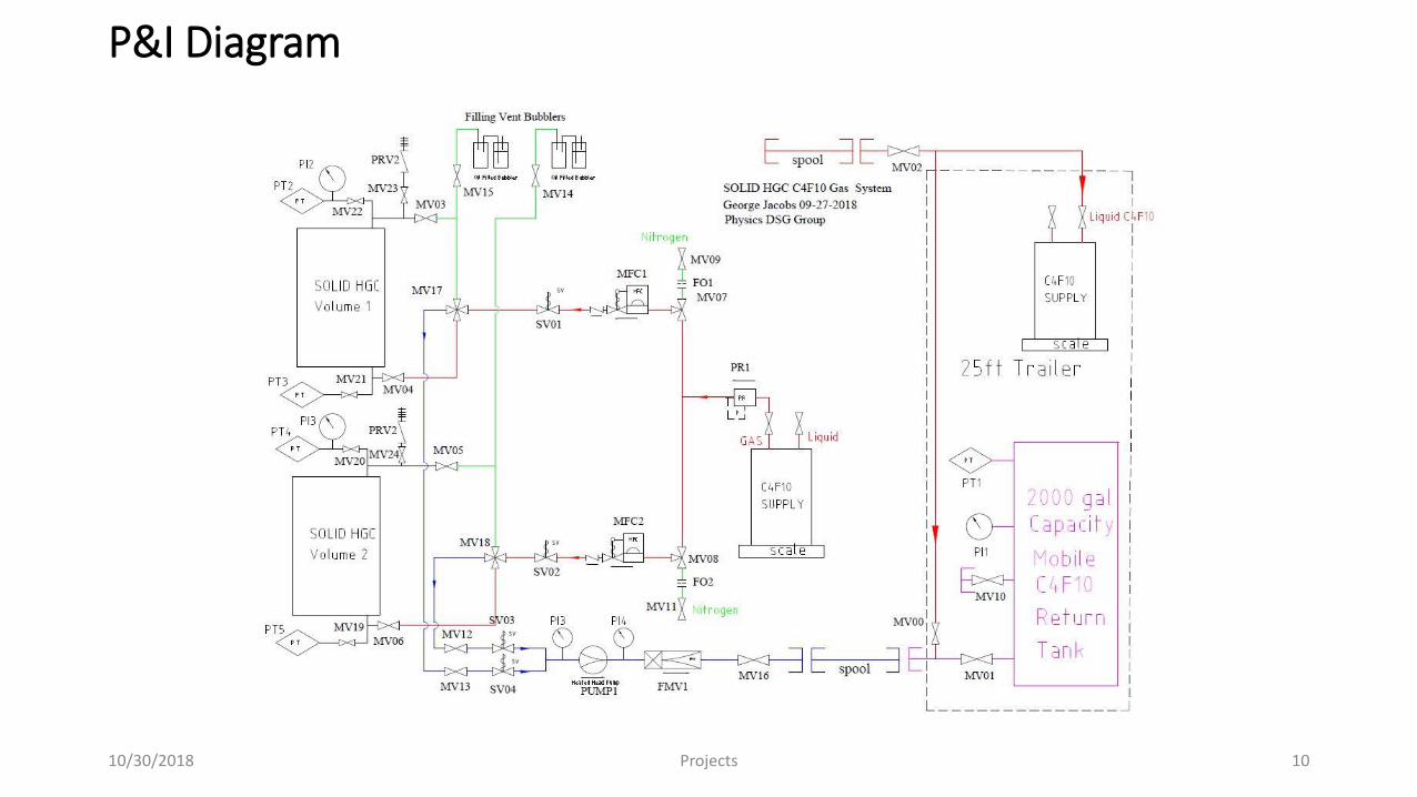
P&I Diagram
10/30/2018 Projects 10
Hall B Gas System’s Controls and Monitoring System
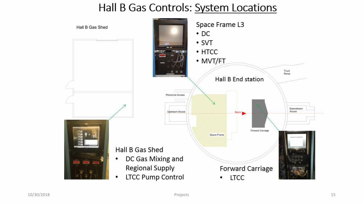
• Five Controls and Monitoring systems supply six detectors.DC (Mixing and Supply)HTCC (Supply)LTCC (Supply)SVT (Supply)MVT/FT (Mixing)
• Installation completed in Q4 2017.
• System provides automated controls for DC and MVT/FT mixing systems.
• Intuitive monitoring and control screens for technical staff.
• Provides data for the Hall B EPICS alarms system
10/30/2018 Projects 11
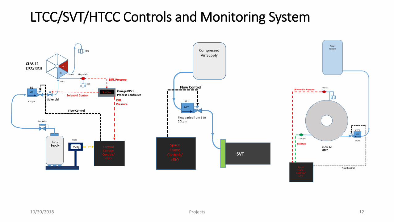
LTCC/SVT/HTCC Controls and Monitoring System
10/30/2018 Projects 12
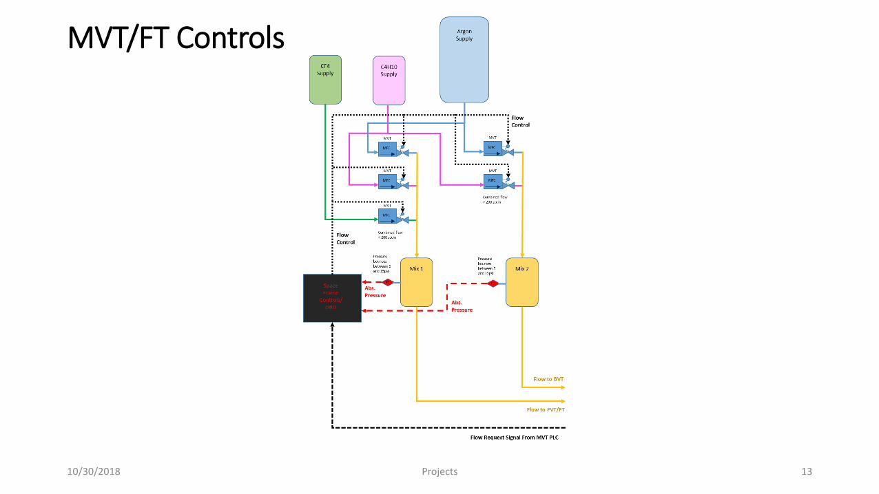
MVT/FT Controls
10/30/2018 Projects 13
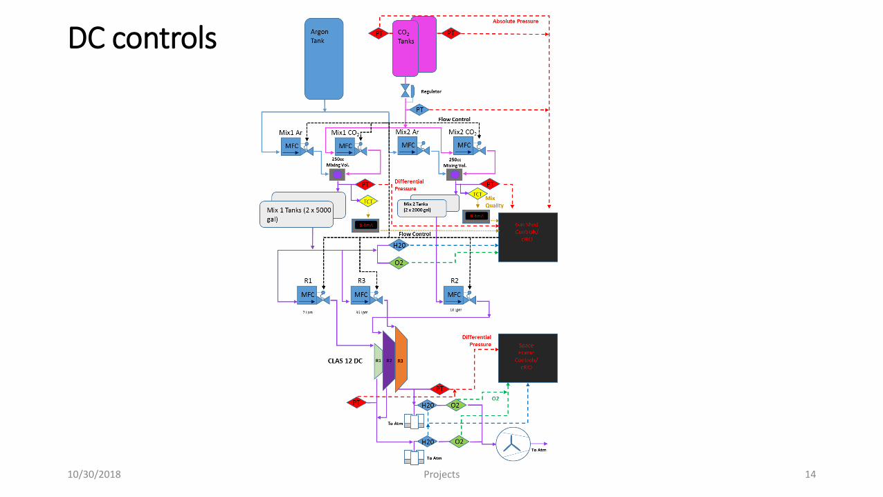
DC controls
10/30/2018 Projects 14
10/30/2018 Projects 15
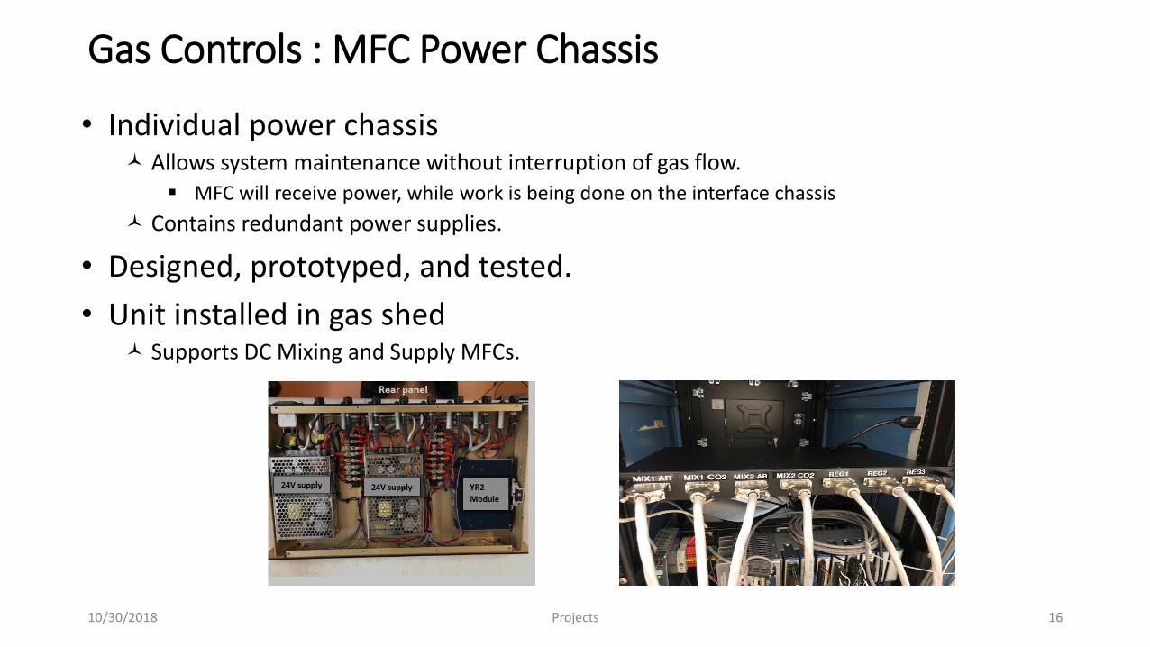
Gas Controls : MFC Power Chassis
• Individual power chassis Allows system maintenance without interruption of gas flow.
MFC will receive power, while work is being done on the interface chassis
Contains redundant power supplies.
• Designed, prototyped, and tested.
• Unit installed in gas shed Supports DC Mixing and Supply MFCs.
10/30/2018 Projects 16

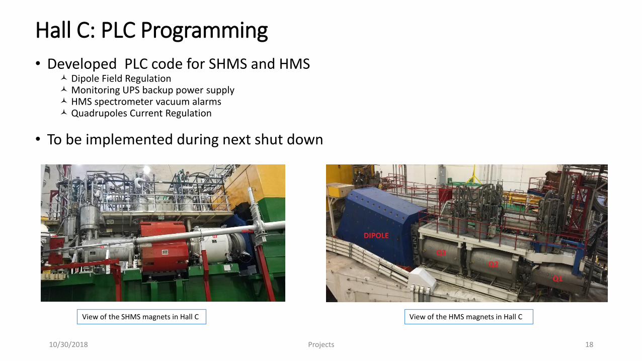
Hall C: PLC Programming
• Developed PLC code for SHMS and HMS Dipole Field Regulation Monitoring UPS backup power supply HMS spectrometer vacuum alarms Quadrupoles Current Regulation
• To be implemented during next shut down
View of the HMS magnets in Hall CView of the SHMS magnets in Hall C
Projects10/30/2018 18
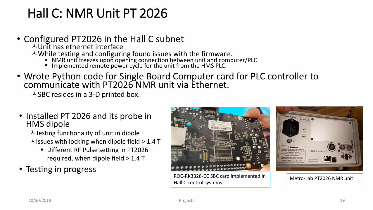
Hall C: NMR Unit PT 2026
• Configured PT2026 in the Hall C subnetUnit has ethernet interfaceWhile testing and configuring found issues with the firmware.
NMR unit freezes upon opening connection between unit and computer/PLC Implemented remote power cycle for the unit from the HMS PLC.
• Wrote Python code for Single Board Computer card for PLC controller to communicate with PT2026 NMR unit via Ethernet.SBC resides in a 3-D printed box.
ROC-RK3328-CC SBC card implemented in Hall C control systems
Metro-Lab PT2026 NMR unit
Projects10/30/2018 19
• Installed PT 2026 and its probe in HMS dipoleTesting functionality of unit in dipoleIssues with locking when dipole field > 1.4 T
Different RF Pulse setting in PT2026 required, when dipole field > 1.4 T
• Testing in progress
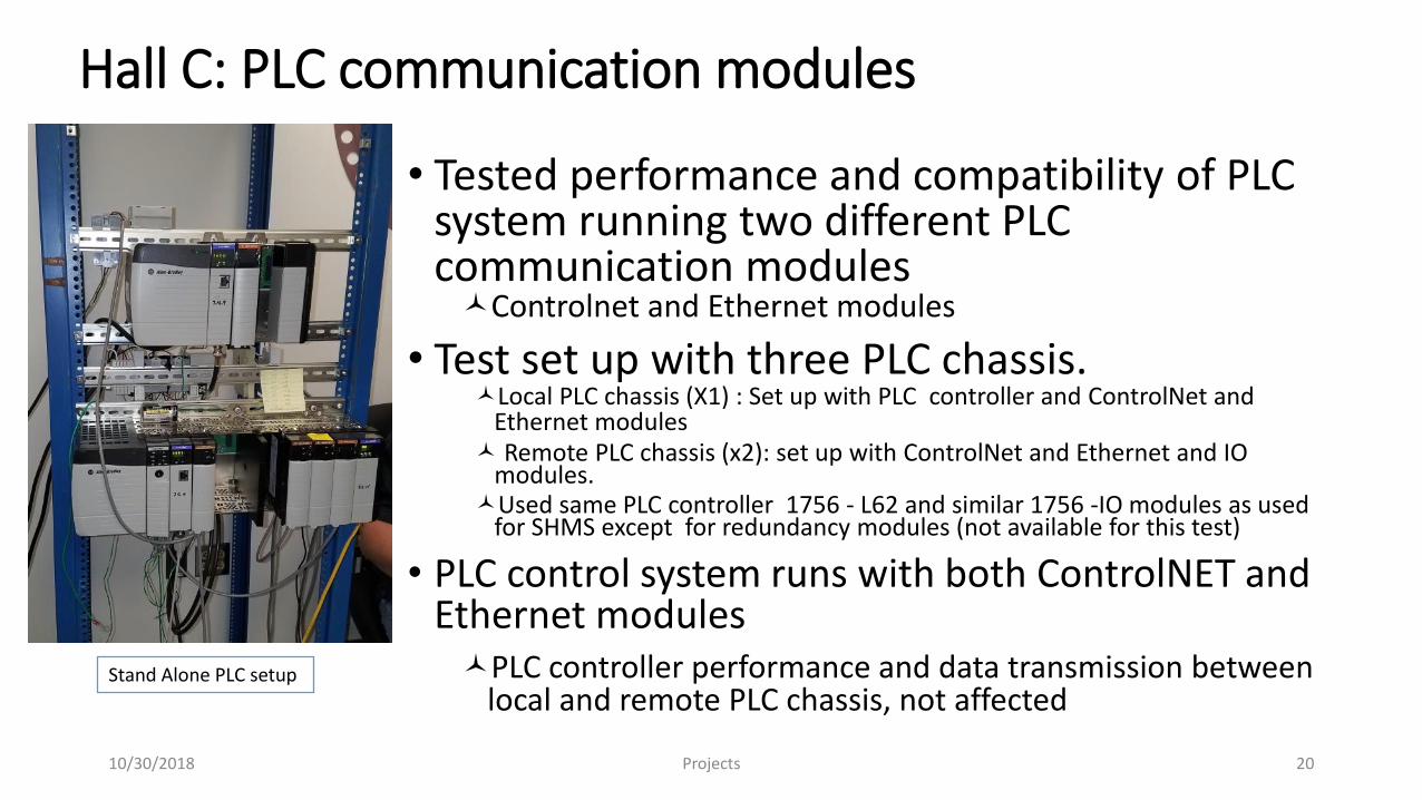
Hall C: PLC communication modules
• Tested performance and compatibility of PLC system running two different PLC communication modulesControlnet and Ethernet modules
• Test set up with three PLC chassis.Local PLC chassis (X1) : Set up with PLC controller and ControlNet and
Ethernet modules Remote PLC chassis (x2): set up with ControlNet and Ethernet and IO
modules.Used same PLC controller 1756 - L62 and similar 1756 -IO modules as used
for SHMS except for redundancy modules (not available for this test)
• PLC control system runs with both ControlNET and Ethernet modulesPLC controller performance and data transmission between
local and remote PLC chassis, not affectedStand Alone PLC setup
Projects10/30/2018 20
Hall C: SHMS PLC upgrades
Converted PLC control systems from version 16 to version 20Note: Highest version supported by the SHMS PLC controller (1756-L62) is the version 20.58
Upgraded:
• Redundancy modules, communication modules
• Rockwell’s PLC software on Windows 7 computers • Skylla7 and Controls7 (computer/laptop)
RSLOGIX5000 v20. RSNetworks v26. for Ethernet and ControlnetControlFlash v15
• Firmware for Primary and Secondary SHMS PLC chassis:1756-L62 PLC controllers from version 16 to Version 201756-RM redundancy modules 1756-EN2T Ethernet modules1756- CN2B ControlNet modules
Projects10/30/2018 21
Hall C: SHMS PLC upgrades
• Re-synchronized redundancy configuration between primary and secondary PLC chassis.
• Swapped Controlnet modules with Ethernet modules for SHMS Quadrupole 1 and Heater Exchanger PLC chassis
Reason: On several occasions Controlnet modules lost communication with Local PLC, affecting cryogenics in halls
Configured new 1756-EN2T and ENBT Ethernet modules Assigned and tested modules in the Hall C subnet Generated new SHMS project file with the module modifications.
System configured with two remote chassis communicating with the Local PLC chassis via Ethernet and the remain six PLC remote chassis via ControlNet network.
• Both type of module work in parallel
Projects10/30/2018 22
Hall C: Windows 7 End of Life
• Support for Windows 7 by computer center ends January 2020
• Researched Windows 10 compatibility requirements for HMS and SHMS control systems
• Tested Windows 10 compatibility with SHMSRebuilt “dsg-hallc-6” windows 7 computer with windows 10Configured computer on Hall C Dev subnet.Installed required Rockwell software to run PLC control systemsWent on line with SHMS PLC
• Selected PLC software and firmware upgrades for SHMS control systems run in Windows 10 environment
Projects10/30/2018 23
Hall D Solenoid
• Maintenance/Improvements of existing FastDAQ systemNational Instruments PXIe8x 16-bit 8 channel ADC modules
Samples @ 250 kHz, data exported @ 10 kHz
• Upgraded controllerIncreased data rate from 5 to 10 kHz (previous controllers obsolete)
• Installation of additional ADC modulesMonitor additional voltage splices, accelerometers
• Perform annual calibration of ADC modulesAutomate procedure to reduce time required
Projects10/30/2018 24
Current Activities
• Pre-power-up interlock procedure performed prior to full current magnet operation to verify I&C interlocks are operationalB00000400-P005
• Pre-power-up instrumentation checkout performed prior to full current magnet operation to verify I&C interlocks are operationalB00000400-P003
• Provide off hour on call support for magnet controls support (Amanda, Brian, Tyler, Pablo)
10/30/2018 Projects 25
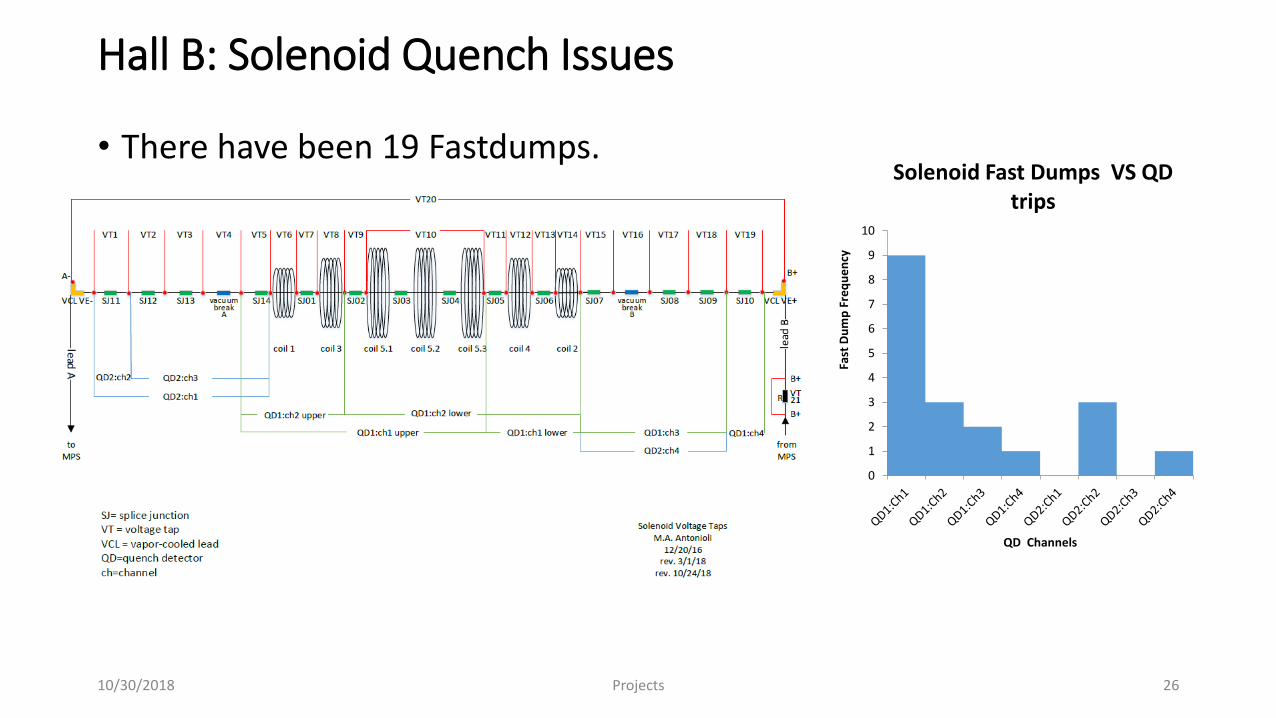
Hall B: Solenoid Quench Issues
• There have been 19 Fastdumps.
10/30/2018 Projects 26
0
1
2
3
4
5
6
7
8
9
10
Fast
Du
mp
Fre
qu
en
cy
QD Channels
Solenoid Fast Dumps VS QD trips
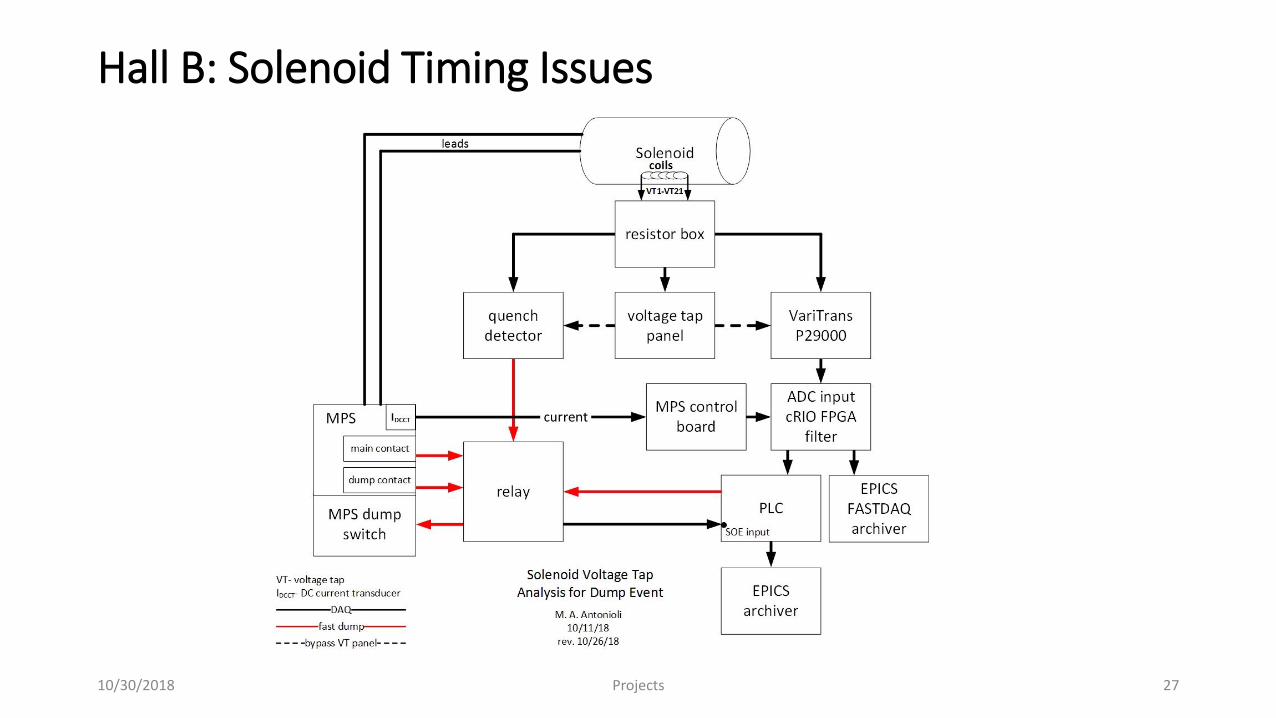
Hall B: Solenoid Timing Issues
Projects10/30/2018 27
HallB: Solenoid Solenoid Issues
• Analysis of timing issues between SOE, FastDAQ, and power supply contactor
• Analysis of voltage tap values Quench detectors appear to trip on shorter than set value of time over thresholdChecking of quench detector potentiometers
• Investigation of stresses on solenoid and torus
10/30/2018 Projects 28
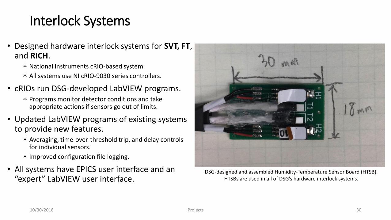
Interlock Systems
• Designed hardware interlock systems for SVT, FT, and RICH.National Instruments cRIO-based system.
All systems use NI cRIO-9030 series controllers.
• cRIOs run DSG-developed LabVIEW programs. Programs monitor detector conditions and take
appropriate actions if sensors go out of limits.
• Updated LabVIEW programs of existing systems to provide new features.Averaging, time-over-threshold trip, and delay controls
for individual sensors.
Improved configuration file logging.
• All systems have EPICS user interface and an “expert” LabVIEW user interface.
DSG-designed and assembled Humidity-Temperature Sensor Board (HTSB).HTSBs are used in all of DSG’s hardware interlock systems.
Projects10/30/2018 30

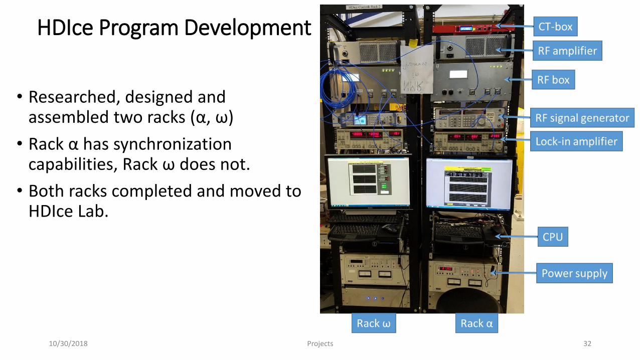
HDIce Program Development
• Researched, designed and assembled two racks (α, ω)
• Rack α has synchronization capabilities, Rack ω does not.
• Both racks completed and moved to HDIce Lab.
10/30/2018 Projects 32
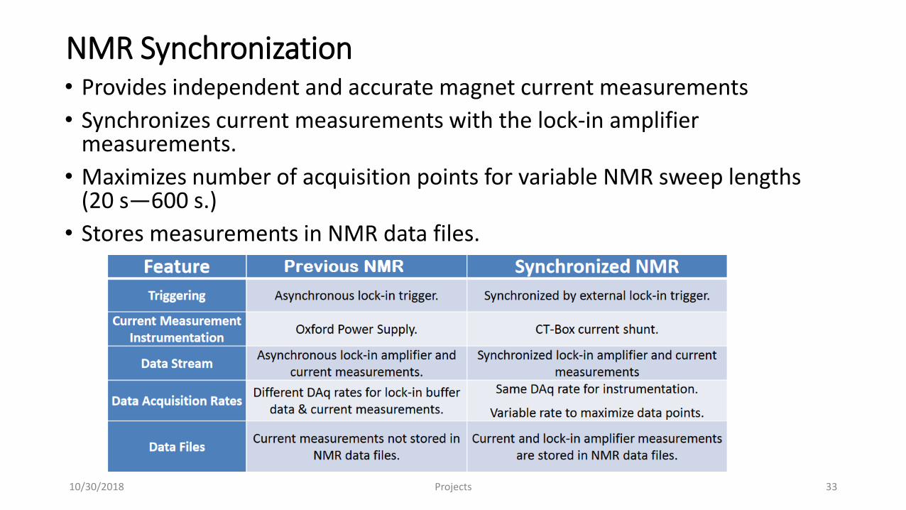
NMR Synchronization• Provides independent and accurate magnet current measurements
• Synchronizes current measurements with the lock-in amplifier measurements.
• Maximizes number of acquisition points for variable NMR sweep lengths (20 s―600 s.)
• Stores measurements in NMR data files.
Projects10/30/2018 33
CAENels CT-Box
• Synchronization with CAENels CT-Box (brand new product)
• Product issues with Firmware errors required updates.Hardware issues.Lack of documentation on software protocols.Not shipped with software we could use.Required extensive development of a library of LabVIEW device drivers.Developed LabVIEW Daq code using DSG device driver library
Tested CT-Box.
• All issues resolved
Projects10/30/2018 34
Synchronization Programs
• Developed data acquisition program CT-Box .Tested CT-Box data acquisition and triggering.
• Developed test program for lock-in amplifierUsed with CT-Box data acquisition program to test:
Lock-in amplifier data acquisition. Data buffer storage and read-out. Lock-in amplifier dual data stream. Lock-in amplifier external triggering capabilities and limitations.
10/30/2018 Projects 35
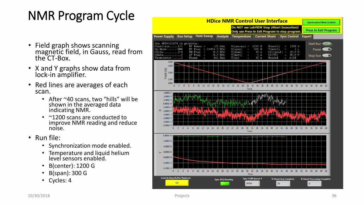
NMR Program Cycle
• Field graph shows scanning magnetic field, in Gauss, read from the CT-Box.
• X and Y graphs show data from lock-in amplifier.
• Red lines are averages of each scan. • After ~40 scans, two “hills” will be
shown in the averaged data indicating NMR.
• ~1200 scans are conducted to improve NMR reading and reduce noise.
• Run file:• Synchronization mode enabled.• Temperature and liquid helium
level sensors enabled.• B(center): 1200 G• B(span): 300 G• Cycles: 4
10/30/2018 Projects 36
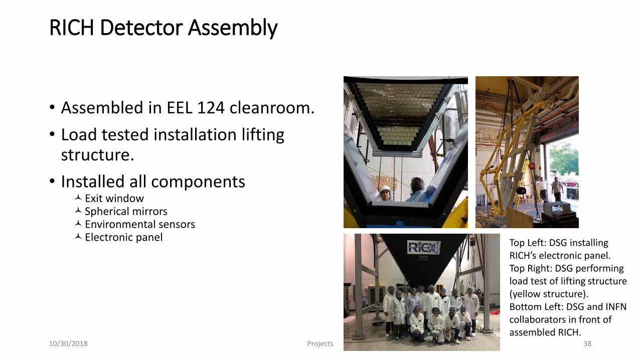
RICH Detector Assembly
• Assembled in EEL 124 cleanroom.
• Load tested installation lifting structure.
• Installed all componentsExit windowSpherical mirrorsEnvironmental sensorsElectronic panel Top Left: DSG installing
RICH’s electronic panel.Top Right: DSG performing load test of lifting structure (yellow structure).Bottom Left: DSG and INFN collaborators in front of assembled RICH.
Projects10/30/2018 38
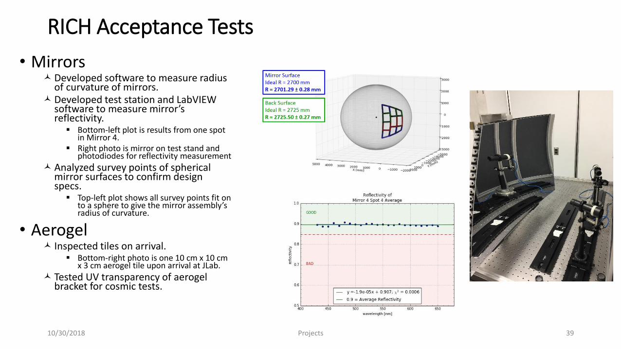
RICH Acceptance Tests
• MirrorsDeveloped software to measure radius
of curvature of mirrors.Developed test station and LabVIEW
software to measure mirror’s reflectivity.
Bottom-left plot is results from one spot in Mirror 4.
Right photo is mirror on test stand and photodiodes for reflectivity measurement
Analyzed survey points of spherical mirror surfaces to confirm design specs.
Top-left plot shows all survey points fit on to a sphere to give the mirror assembly’s radius of curvature.
• Aerogel Inspected tiles on arrival.
Bottom-right photo is one 10 cm x 10 cm x 3 cm aerogel tile upon arrival at JLab.
Tested UV transparency of aerogel bracket for cosmic tests.
Projects10/30/2018 39
• Air-cooling system (top)Atlas-Copco compressors provide 900 slm airflow to RICH Electronics.
• Nitrogen purge system (bottom)Hall B’s boil-off nitrogen dewar supplies 40 slm of nitrogen flow to keep N2 Vol free of
moisture.
Critical for keeping RICH’s aerogel in a low humidity environment.
• Designing an automatic N2 Back-UpNew system will use a pneumatic valve that opens automatically if the main N2 supply pressure
decreases to temporarily suppling RICH with N2 from gas bottles.
All components ordered.
Will install back-up supply during next downtime.
RICH Air-cooling and Nitrogen Purge System
Projects10/30/2018 40
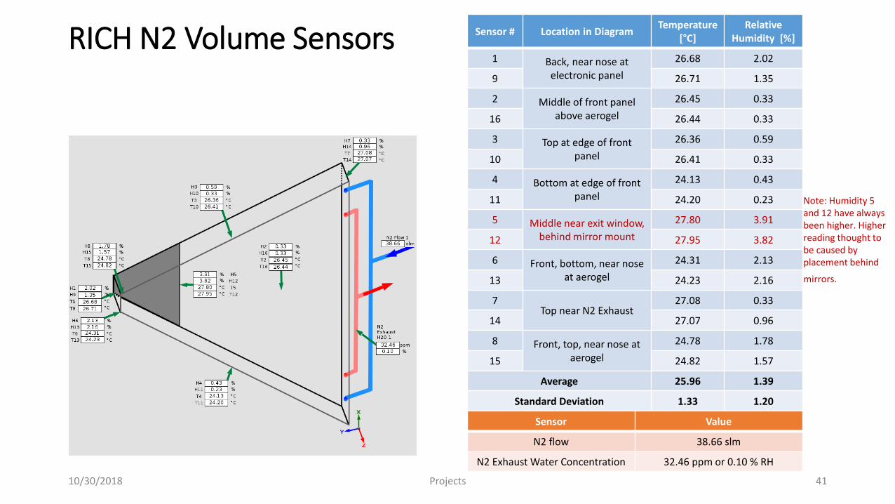
RICH N2 Volume Sensors
10/30/2018 Projects 41
Sensor # Location in DiagramTemperature
[°C]Relative
Humidity [%]
1 Back, near nose at electronic panel
26.68 2.02
9 26.71 1.35
2 Middle of front panel above aerogel
26.45 0.33
16 26.44 0.33
3 Top at edge of front panel
26.36 0.59
10 26.41 0.33
4 Bottom at edge of front panel
24.13 0.43
11 24.20 0.23
5 Middle near exit window, behind mirror mount
27.80 3.91
12 27.95 3.82
6 Front, bottom, near nose at aerogel
24.31 2.13
13 24.23 2.16
7Top near N2 Exhaust
27.08 0.33
14 27.07 0.96
8 Front, top, near nose at aerogel
24.78 1.78
15 24.82 1.57
Average 25.96 1.39
Standard Deviation 1.33 1.20
Note: Humidity 5 and 12 have always been higher. Higher reading thought to be caused by placement behind
mirrors.
Sensor Value
N2 flow 38.66 slm
N2 Exhaust Water Concentration 32.46 ppm or 0.10 % RH
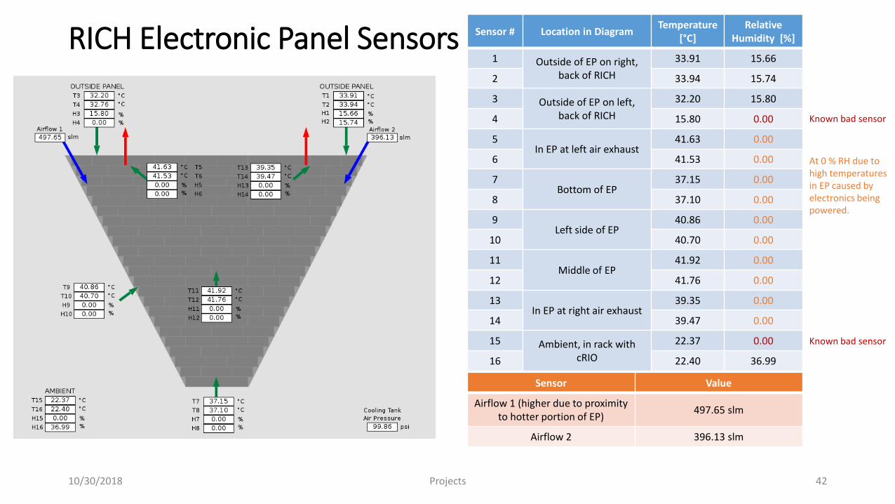
RICH Electronic Panel Sensors
10/30/2018 Projects 42
Sensor # Location in DiagramTemperature
[°C]Relative
Humidity [%]
1 Outside of EP on right,back of RICH
33.91 15.66
2 33.94 15.74
3 Outside of EP on left,back of RICH
32.20 15.80
4 15.80 0.00
5In EP at left air exhaust
41.63 0.00
6 41.53 0.00
7Bottom of EP
37.15 0.00
8 37.10 0.00
9Left side of EP
40.86 0.00
10 40.70 0.00
11Middle of EP
41.92 0.00
12 41.76 0.00
13In EP at right air exhaust
39.35 0.00
14 39.47 0.00
15 Ambient, in rack with cRIO
22.37 0.00
16 22.40 36.99
Sensor Value
Airflow 1 (higher due to proximity to hotter portion of EP)
497.65 slm
Airflow 2 396.13 slm
Known bad sensor
Known bad sensor
At 0 % RH due to high temperatures in EP caused by electronics being powered.
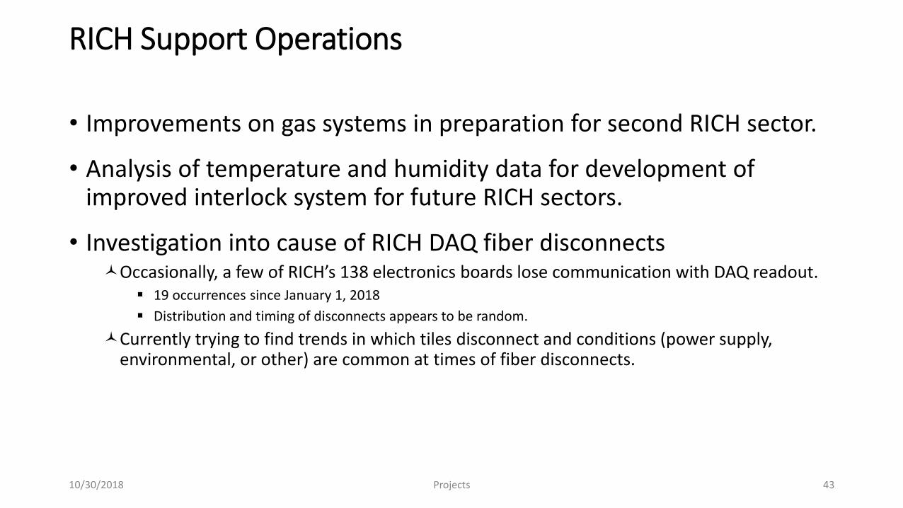
RICH Support Operations
• Improvements on gas systems in preparation for second RICH sector.
• Analysis of temperature and humidity data for development of improved interlock system for future RICH sectors.
• Investigation into cause of RICH DAQ fiber disconnectsOccasionally, a few of RICH’s 138 electronics boards lose communication with DAQ readout.
19 occurrences since January 1, 2018
Distribution and timing of disconnects appears to be random.
Currently trying to find trends in which tiles disconnect and conditions (power supply, environmental, or other) are common at times of fiber disconnects.
Projects10/30/2018 43
SVT
• Current ActivitiesTesting spare modules
Preparations for module replacement
Maintenance of slow controls Hardware interlocks, cabling, etc.
• Designed, developed, installed new patch panel boards
Projects10/30/2018 44
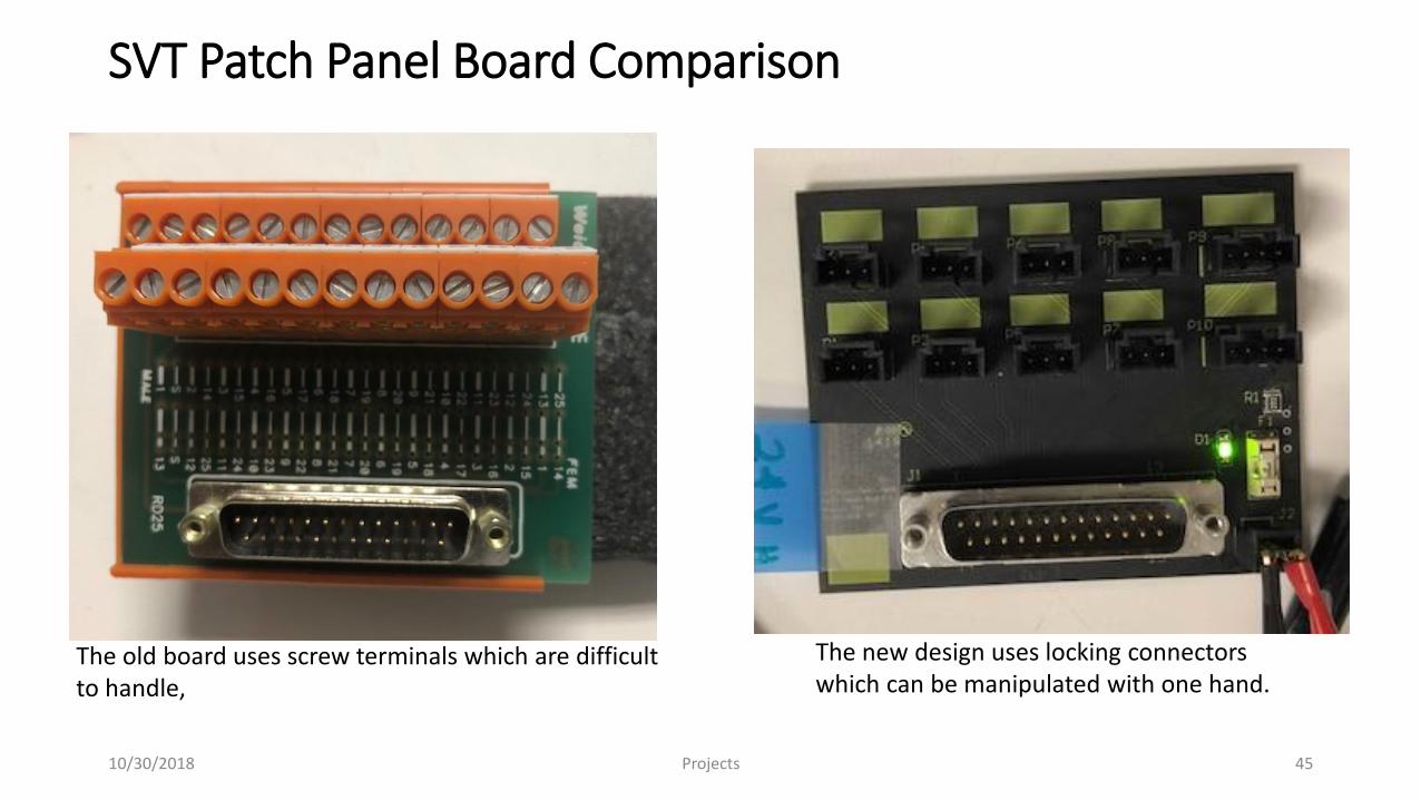
SVT Patch Panel Board Comparison
The old board uses screw terminals which are difficult to handle,
The new design uses locking connectors which can be manipulated with one hand.
Projects10/30/2018 45
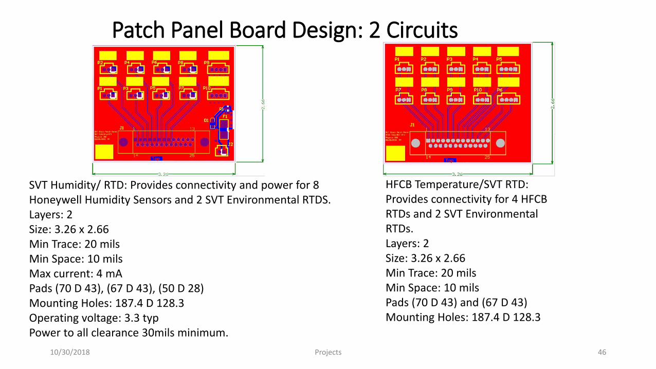
Patch Panel Board Design: 2 Circuits
HFCB Temperature/SVT RTD: Provides connectivity for 4 HFCB RTDs and 2 SVT Environmental RTDs.Layers: 2Size: 3.26 x 2.66Min Trace: 20 milsMin Space: 10 milsPads (70 D 43) and (67 D 43)Mounting Holes: 187.4 D 128.3
Projects10/30/2018 46
SVT Humidity/ RTD: Provides connectivity and power for 8 Honeywell Humidity Sensors and 2 SVT Environmental RTDS.Layers: 2Size: 3.26 x 2.66Min Trace: 20 milsMin Space: 10 milsMax current: 4 mAPads (70 D 43), (67 D 43), (50 D 28)Mounting Holes: 187.4 D 128.3Operating voltage: 3.3 typPower to all clearance 30mils minimum.
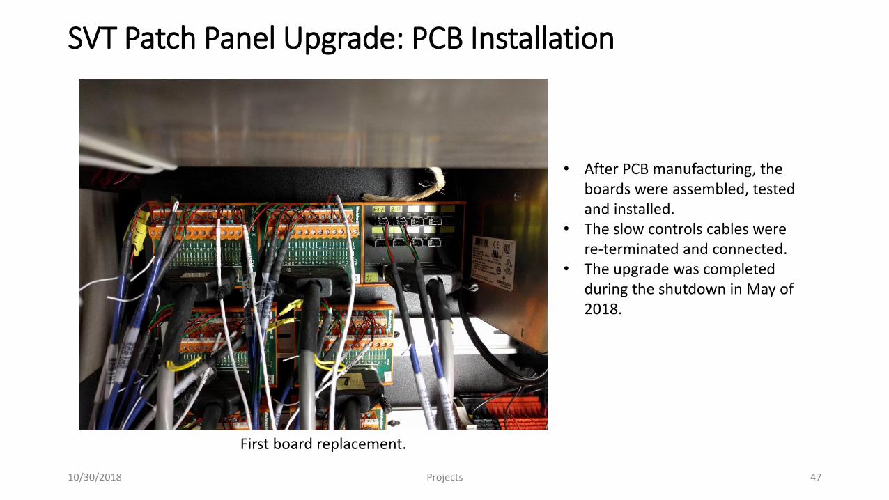
SVT Patch Panel Upgrade: PCB Installation
• After PCB manufacturing, the boards were assembled, tested and installed.
• The slow controls cables were re-terminated and connected.
• The upgrade was completed during the shutdown in May of 2018.
First board replacement.
Projects10/30/2018 47

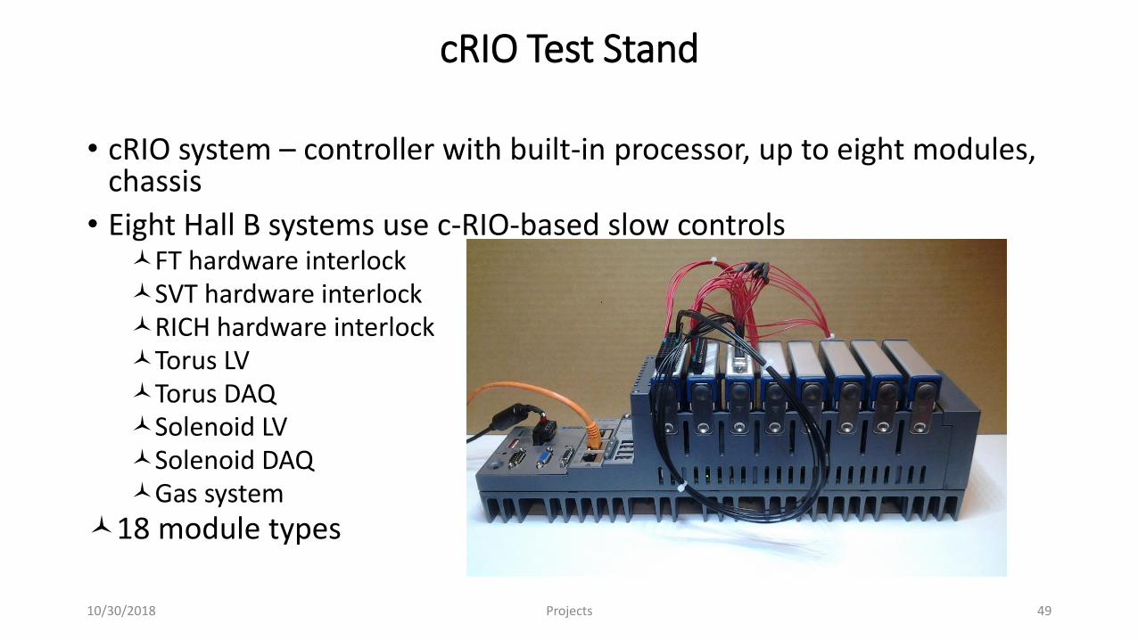
cRIO Test Stand
• cRIO system – controller with built-in processor, up to eight modules, chassis
• Eight Hall B systems use c-RIO-based slow controlsFT hardware interlockSVT hardware interlockRICH hardware interlockTorus LVTorus DAQSolenoid LVSolenoid DAQGas system
18 module types
Projects10/30/2018 49
cRIO Test Stand, cont.
• Code currently being written for analog input modulesNI 9207 module completed; currently working on NI 9205 module
Manual mode – choose one of eight tests to be run on one module channel only
Automatic mode – all eight tests are run on all module channels
Results can be saved in Excel
Projects10/30/2018 50
Conclusion
• DSG is dynamic, pro-active, and works as a team
• Staff exceptionally skilled with software and hardware
• Group has made solid contributions to projects across the physics division
My heartfelt thanks to Dr. Rossi for her delicatesse, support, and guidance
10/30/2018 Projects 51

The End
10/30/2018 Projects 52