Embed Size (px)
Citation preview
Proceedings of 2014 ASME Dynamic Systems and Control ConferenceASME DSCC 2014
October 22-October 24, 2014, San Antonio, USA
DSCC2014-6290
DESIGN AND EXPERIMENTAL VALIDATION OF A VIRTUAL VEHICLE CONTROLCONCEPT FOR TESTING HYBRID VEHICLES USING A HYDROSTATIC
DYNAMOMETER
Zhekang Du, Perry Y. Li∗, Kai Loon Cheong and Thomas R. ChaseCenter of Compact and Efficient Fluid Power
Department of Mechanical EngineeringUniversity of Minnesota,Minneapolis, MN 55455
Email: [email protected], [email protected]*, [email protected], [email protected]
ABSTRACTAn approach to control a hydrostatic dynamometer for
the Hardware-In-the-Loop (HIL) testing of hybrid vehicles hasbeen developed and experimentally tested. The hydrostatic dy-namometer used, which is capable of regeneration, was specif-ically designed and built in-house to evaluate the fuel economyand control strategy of a hydraulic hybrid vehicle. The controlchallenge comes from the inertia of the dynamometer being only3% of that of the actual vehicle so that the dynamometer mustapply, in addition to any drag torques, acceleration/decelerationtorques related to the difference in inertias. To avoid estimatingthe acceleration which would be a non-causal operation, a virtualvehicle concept is introduced. The virtual vehicle model gener-ates a reference speed profile which represents the behavior ofthe actual vehicle if driven on the road. The dynamometer controlproblem becomes one of enabling the actual vehicle-dyno shaftto track the speed of the virtual vehicle, instead of directly ap-plying a desired torque. A feedback/feedforward controller wasdesigned based upon an experimentally validated dynamic modelof the dynamometer. The approach was successfully tested on apower-split hydraulic hybrid vehicle with acceptable speed andtorque tracking performance.
1 IntroductionHardware-In-the-Loop (HIL) simulation is an effective tech-
nique to develop and test complex real-time embedded systems.
A HIL system reduces testing complexity by using only part ofthe hardware which needs to be tested, while interacting with thecomputer simulation of the remaining hardware. HIL is widelyused in the automotive industry to verify performance of produc-tion powertrain controller modules (PCM) [1].
A prototype hydraulic hybrid passenger vehicle testbed isbeing developed within the Center for Compact and EfficientFluid Power (CCEFP) to advance hydraulic hybrid technologies.While simulations can predict fuel economy and performanceof the vehicle, experimental validation is still necessary. Out-door road testing requires a test track and results are not veryrepeatable due to environmental conditions. A reliable HIL sys-tem, such as a dynamometer (or dyno in short), can enable re-liable and consistent measurements without the environmentalinfluence such as wind, weather, tire pressure, and traffic. Fur-thermore, a dynamometer allows the comparison, development,and tuning of various control strategies for different vehicle anddriving conditions. To this end, a hydrostatic dynamometer withmotoring capability, necessary for hybrid vehicles, has been de-veloped in our group recently [2].
Commercial chassis dynamometers usually have heavyroller drums to simulate the vehicle inertia. The rolling massis designed to be close to the vehicle inertia so that when the ve-hicle is accelerating/decelerating, most of the inertia effect is au-tomatically taken care of by the rolling mass. The dynamometerneeds only compensate for the road/aerodynamic drag which canbe calculated directly from the wheel speed. On the other hand,
hydrostatic dynamometers which use hydraulic pump/motors toprovide the braking or regeneration torque on the vehicle, havesuperior power-to-weight ratio, small inertias for flexibility, aretherefore more compact and low cost. For example, the inertiaof the dynamometer in [2] is around 3% of the intended vehicleinertia even with the addition of a small flywheel. A unique chal-lenge for dynomometer control is the requirement to emulate theacceleration/deceleration loads related to the large difference ininertia. One approach is to apply the torque according to the ac-celeration estimate from a Kalman filter [3]. However, this is aninherently non-causal process since acceleration is dependent onthe torque applied by the powertrain and the dynamometer. Sincethe applied dyno torque should be a function of the acceleration,any delay in estimation inevitably leads to inaccurate emulationwhen acceleration/deceleration is high.
To accurately control a low inertia dynamometer to emulatethe dynamic load on a vehicle, a virtual vehicle control concept isproposed here. The main idea is to introduce a virtual vehicle dy-namic model with information on the intended vehicle inertia androad and aerodynamic drag characteristics. For a given appliedvehicle torque, this model generates, in real time, a reference ve-hicle speed which represents the behavior of the vehicle with theintended vehicle inertia and environmental drag conditions. Thecontrol objective for the dynamometer becomes one of exertingthe correct torque so that the actual speed of the common vehicle-dyno shaft follows that of the reference generated by the virtualvehicle model. The need for the non-causal acceleration estima-tion can thus be avoided. When the actual speed tracks the virtualreference speed, the hypothesis is that the torque applied by thedyno on the vehicle will be exactly the same load as if the vehicleis driving on the ground with full effect of the intended vehicleinertia and road resistance. A variety of control algorithms canbe designed to ensure that the vehicle-dyno shaft speed tracksthe virtual vehicle speed. In this paper, we use a combination offeedforward control of the required dyno torque for tracking thevirtual vehicle reference model, and a feedback stabilization de-signed based upon affine parameterization and sensitivity shap-ing. The controller has been implemented on the dynamometerand the virtual vehicle control concept has been experimentallyvalidated.
In the literature, development and use of hydraulic dy-namometers have focused on testing engine performances [4–9].One of the earliest report of dynamometer for testing a completepower-train, with simulated load and engine, is found in [10].Control studies of hydraulic dynamometer in the literature arefew. In [11], a generalized framework to analyze and designcontrollers for a class of dynamic emulation systems using anindirect control input is presented. A feedforward control is usedto avoid limitations imposed by stability considerations in feed-back designs to improve performance. The controller in [9] isdesigned based on direct estimation of engine speed and acceler-ation.
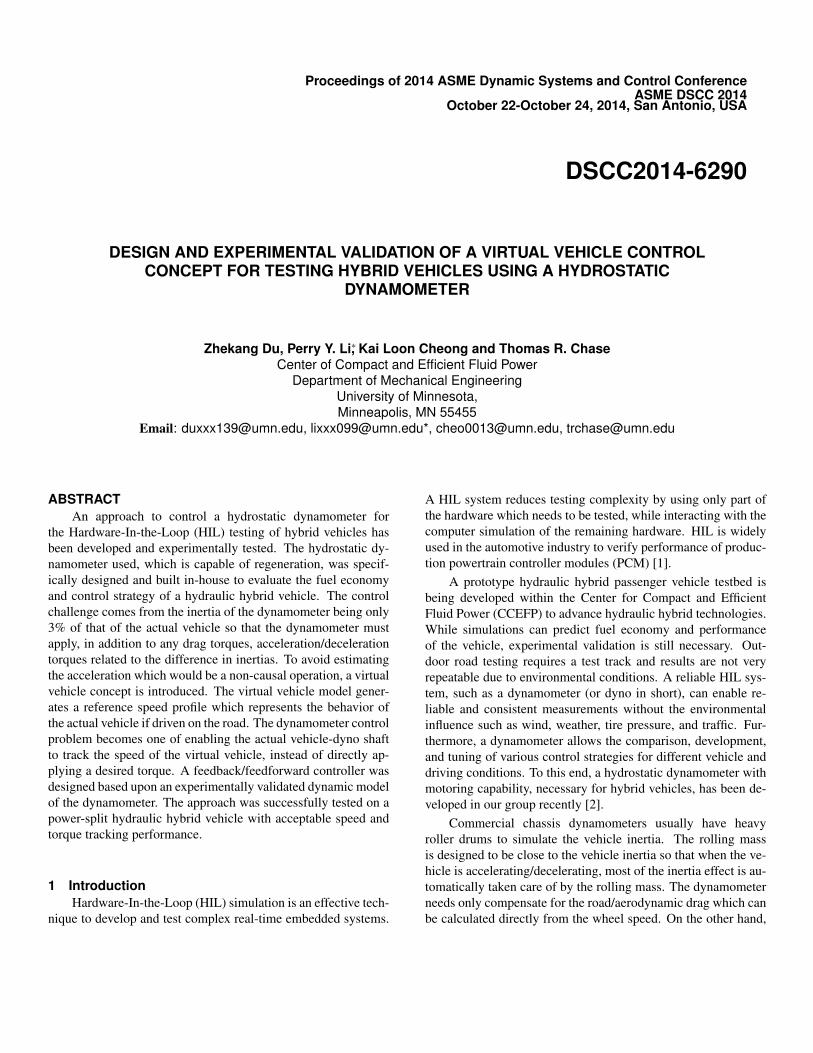
FIGURE 1. Schematic of Hydrostatic Dynamometer
The rest of the paper is organized as follows: Section 2 il-lustrates the configuration of the hydrostatic dynamometer. Sec-tion 3 explains the virtual vehicle control concept. Section 4 de-scribes the modeling and system identification of the dyno sys-tem. Section 5 discusses the controller design. Section 6 presentsthe experimental results. Section 7 contains concluding remarksof this study with future work.
2 System DescriptionThe hydrostatic dynamometer system consists of a hydraulic
power supply unit, an accumulator, a proportional directionalvalve and two tandem swash plate pump/motors (Fig. 1). Thedisplacements of the pump/motor are used as the primary con-trol input to control the load on the vehicle. By operating themin pumping or motoring modes, both load absorbing and regen-erating events can be emulated. The proportional valve is nor-mally fully opened to allow unobstructed fluid flow, but it canalso be used as the secondary high bandwidth control in case thepump/motor displacement actuation is deemed too slow. Theyare not used this way in the current study. During load absorbingevents, energy from the vehicle is used to charge the hydraulicaccumulator. During regenerating events, energy in the hydraulicaccumulator is discharged and returned to the vehicle. The hy-draulic power unit is used to ensure that the accumulator main-tains a sufficiently high pressure in all events.
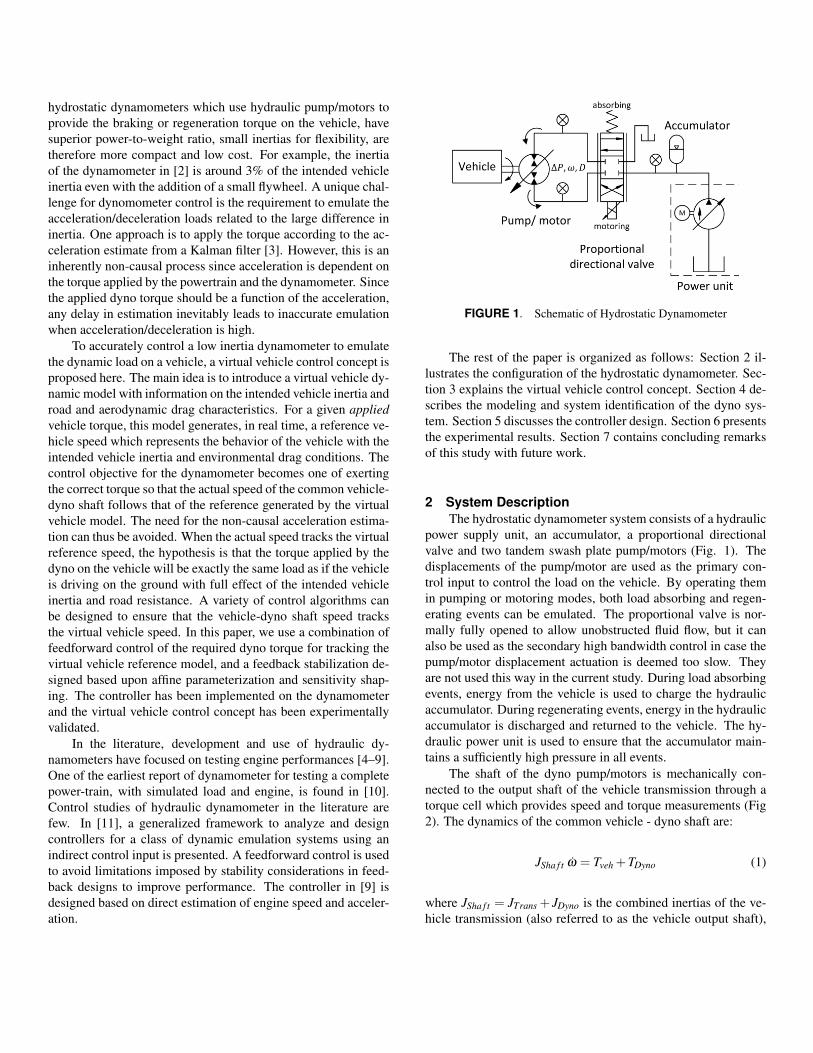
The shaft of the dyno pump/motors is mechanically con-nected to the output shaft of the vehicle transmission through atorque cell which provides speed and torque measurements (Fig2). The dynamics of the common vehicle - dyno shaft are:
JSha f t ω̇ = Tveh +TDyno (1)
where JSha f t = JTrans + JDyno is the combined inertias of the ve-hicle transmission (also referred to as the vehicle output shaft),
JTrans, and of the dyno, JDyno. Tveh is the applied vehicle torqueon the transmission output shaft, TDyno is the applied dyno torqueand Tmeas is the torque cell measurement. Because the vehicle isstationary in dynomometer testing, JTrans is only a small fractionof the equilvalent intended vehicle inertia. In our system, whichincorporates a small flywheel, JSha f t represents ≈ 3% of the in-tended vehicle inertia.
By considering the individual dynamics of the dyno inertiaand the vehicle output shaft inertia (e.g. via the two free bodiesobtained by cutting the transmission output shaft at the torquecell in Fig. 2), the torque cell measurement can be shown tobe a combination of the vehicle applied torque and dyno appliedtorque:
Tmeas =−JDyno
JSha f tTveh +
JTrans
JSha f tTDyno (2)
Only when JDyno � JTrans can one assume that the measuredtorque is the vehicle applied torque Tveh. This is true in ourcase, since the dynamometer has been augmented with a smallflywheel so that JDyno = 0.2436Kgm2 and JTrans = 0.0064Kgm2.
3 “Virtual Vehicle” dynamometer control concept3.1 Virtual Vehicle dynamics
The virtual vehicle dynamics mimic the behavior of the in-tended vehicle to be tested given the applied vehicle torque. Thisincludes the inertial dynamics as well as any aerodynamics androad drag. In terms of longitudinal vehicle speed v, they are:
Mveh v̇ = Fveh−Fdrag(v) (3)
where Mveh is the vehicle inertia and Fdrag(v) is the road and winddrag, Fveh is the applied traction force.
Eq.(3) is converted to the rotational domain in terms of therotation speed of the transmission output shaft ωveh = Rdi f f /Rw ·v (where Rdi f f and Rw are the ratio of the output differential gear
FIGURE 2. Free body diagram of vehicle - dyno shaft
and the wheel radius):
Jveh ω̇veh = Tveh︸︷︷︸Rw
Rdi f fFveh
−Tdrag(ωveh)︸ ︷︷ ︸Rw
Rdi f fFdrag(v)
(4)
where Jveh = MvehR2
wR2
di f fis the equivalent vehicle inertia with re-
spect to the transmission output port.In order for the dynamometer to emulate on-the-road driv-
ing, from Eqs.(4) and (1), the dynamometer shoud apply on thevehicle output shaft the load of:
TDyno =−(Jveh− JSha f t)ω̇veh−Tdrag(ωveh) (5)
where the first term corresponds to the difference in inertia, andthe second term corresponds to aerodynamic and road drag. Notethat direct implementation of (5) is not strictly possible sincethe measurement or estimation of the acceleration ω̇veh is non-causal. Specifically, the acceleration is dependent on the controlTDyno applied to it in (1).
However, given a measurement or estimate of the appliedvehicle torque T̂veh, the expected transmission output shaft speedprofile ωveh(t) can be computed in real time:
Jveh ω̇veh = T̂veh−Tdrag(ωveh) (6)
Eq.(6) is referred to as the “virtual vehicle” model, and ωveh asthe “virtual vehicle” (shaft) speed.
3.2 Control ConceptTo avoid the non-causal estimation of acceleration as in [3],
instead of implementing Eq.(5) directly, the dynamometer willcontrol the actual combined dyno-vehicle shaft dynamics (ω inEq.(1)) to rotate according to the virtual vehicle speed (ωveh)(computed in real time based on the measurement or an estimateof the applied vehicle torque Tveh and the virtual vehicle dynam-ics in Eq.(6)).
Suppose that the estimate of the vehicle torque T̂veh is accu-rate, and indeed we are successul in making ω(t)→ωveh(t), thencomparing Eqs.(1) and (4), the dynamometer torque would be:
TDyno =−Jsha f t
JvehTdrag(ω)−
Jveh− JSha f t
JvehTveh (7)
With substitution of Tveh using Eq.(1) gives:
TDyno =−(Jveh− JSha f t)ω̇−Tdrag(ω) (8)
which is exactly the desired dynamometer torque in Eq.(5) thatcould not be implemented directly.
The advantage of this approach is that the original task of atorque control problem becomes a speed control problem. whichrespects system causality. Moreover, it allows one to test differ-ent vehicles under different road conditions by simply tuning theparameters for the virtual vehicle dynamics (6).
4 Modeling and Identification of the DynamometerDynamicsThe hydrostatic dyno torque is modeled as a first order sys-
tem:
TDyno =−bω +η∆P2π
D(t)
D(s) =aDmax
s+aU(s)
(9)
where ∆P = PH −PL is the difference in pressures in the highand low pressure accumulators, D(t) is the actual displacementof the pump/motor, Dmax is the maximum displacement of thepump/motor, a is the bandwidth of the swashplate dynamics,b is the damping coefficient in the dyno and U ∈ [0,1] is thenormalized displacement command input, and η(∆P,D) is thepump/motor’s mechanical efficiency map. ∆P = 2100psi is de-signed to be constant in this system.
The parameters in (9) have been estimated. Damping coeffi-cient b≈ 0.0667 is obtained from experimental testing and fromthe manufacturers data sheets, it is estimated that the efficiencyη ≈ 0.8 during operation, and the displacement actuation timeconstant 1/a≈ 0.18sec. In addition, the combined inertia of thedyno/transmission shaft was estimated to be Jsha f t = 0.25kgm2.From these physical parameters, combining Eq.(1) and (9), theopen loop transfer function from pump/motor command U(s) tothe shaft speed ω(s) (see Fig.3) is predicted to be:
GphyOL (s) =
ω(s)U(s)
=a ·K
(s+a)(Js+b)
=2595
(s+5.5556)(s+0.2668). (10)
where K = η∆PDmax/(2π).
System identification experiments have also been performedin closed loop where a proportional feedback gain of Kp = 0.001and a series of sinusoidal reference speeds were applied. The
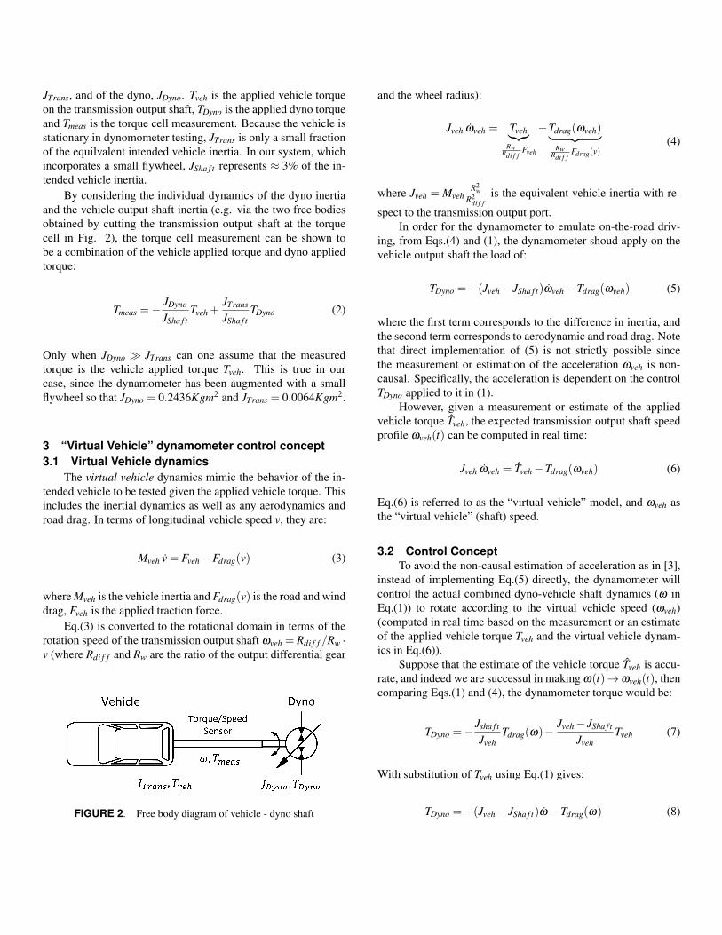
FIGURE 4. Frequency response of the closed loop transfer functionGp(s) using a proportional control gain of Kp = 0.001: a) from physicalparameter based open loop model (green: white-box model), b) modelfrom system identification (red: black box model), c) experiments.
closed loop transfer function was identified to be:
Gp(s) =KpGOL(s)
1+KpGOL(s)=
2.835s2 +5.9s+4.5
(11)
=2.835
(s+0.9)(s+5)
The unwraped open loop system from Gp(s) is:
GidOL(s) =
2835(s+5.6028)(s+0.2972)
(12)
The predicted transfer function Eq.(10) and the experimen-tally identified model Eq.(12) are quite close. Fig. 4 shows thatthe closed loop frequency responses from both these two openloop models compare well with the experimentally obtained fre-quency responses.
5 Hydrostatic Dynamometer Reference speed track-ing controlIn this section, we design a controller that enables the com-
bined dyno/transmission shaft ω in (1) to track the virtual ve-hicle speed ωveh as given in (6). The control scheme (Fig. 3)consists of a feedforward and a feedback component. The ma-jority of the control effort is provided by the feedforward con-troller to provide drag torques and to compensate for effectsdue to difference in inertia between the intended vehicle and thedyno/transmission. The feedback controller is designed to ac-count for model uncertainty and disturbances.
5.1 Estimation of vehicle torque Tveh(t)The estimate of the vehicle applied torque T̂veh(t) is used to
drive the virtual vehicle dynamics in Eq. (6) and in the design ofthe feedforward control term. It is obtained as follows. Consider
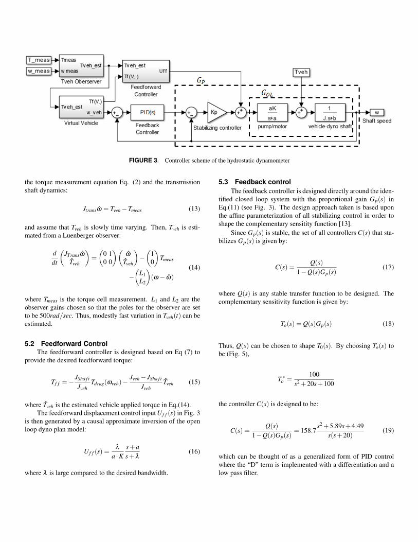
FIGURE 3. Controller scheme of the hydrostatic dynamometer
the torque measurement equation Eq. (2) and the transmissionshaft dynamics:
Jtransω̇ = Tveh−Tmeas (13)
and assume that Tveh is slowly time varying. Then, Tveh is esti-mated from a Luenberger observer:
ddt
(JTransω̂
T̂veh
)=
(0 10 0
)(ω̂
T̂veh
)−(
10
)Tmeas
−(
L1L2
)(ω− ω̂)
(14)
where Tmeas is the torque cell measurement. L1 and L2 are theobserver gains chosen so that the poles for the observer are setto be 500rad/sec. Thus, modestly fast variation in Tveh(t) can beestimated.
5.2 Feedforward ControlThe feedforward controller is designed based on Eq (7) to
provide the desired feedforward torque:
Tf f =−JSha f t
JvehTdrag(ωveh)−
Jveh− JSha f t
JvehT̂veh (15)
where T̂veh is the estimated vehicle applied torque in Eq.(14).The feedforward displacement control input U f f (s) in Fig. 3
is then generated by a causal approximate inversion of the openloop dyno plan model:
U f f (s) =λ
a ·Ks+as+λ
(16)
where λ is large compared to the desired bandwidth.
5.3 Feedback controlThe feedback controller is designed directly around the iden-
tified closed loop system with the proportional gain Gp(s) inEq.(11) (see Fig. 3). The design approach taken is based uponthe affine parameterization of all stabilizing control in order toshape the complementary sensitity function [13].
Since Gp(s) is stable, the set of all controllers C(s) that sta-bilizes Gp(s) is given by:
C(s) =Q(s)
1−Q(s)Gp(s)(17)
where Q(s) is any stable transfer function to be designed. Thecomplementary sensitivity function is given by:
To(s) = Q(s)Gp(s) (18)
Thus, Q(s) can be chosen to shape T0(s). By choosing To(s) tobe (Fig. 5),
T ∗o =100
s2 +20s+100
the controller C(s) is designed to be:
C(s) =Q(s)
1−Q(s)Gp(s)= 158.7
s2 +5.89s+4.49s(s+20)
(19)
which can be thought of as a generalized form of PID controlwhere the “D” term is implemented with a differentiation and alow pass filter.
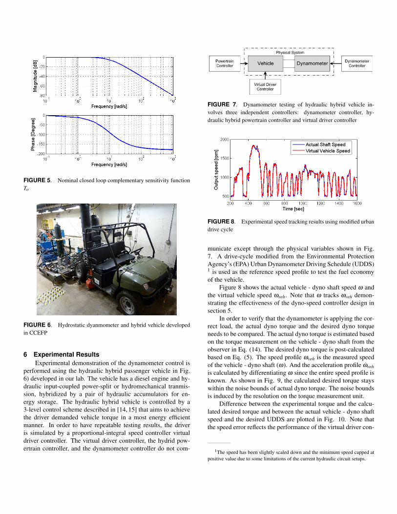
FIGURE 5. Nominal closed loop complementary sensitivity functionTo
FIGURE 6. Hydrostatic dyanmometer and hybrid vehicle developedin CCEFP
6 Experimental ResultsExperimental demonstration of the dynamometer control is
performed using the hydraulic hybrid passenger vehicle in Fig.6) developed in our lab. The vehicle has a diesel engine and hy-draulic input-coupled power-split or hydromechanical tranmis-sion, hybridized by a pair of hydraulic accumulators for en-ergy storage. The hydraulic hybrid vehicle is controlled by a3-level control scheme described in [14, 15] that aims to achievethe driver demanded vehicle torque in a most energy efficientmanner. In order to have repeatable testing results, the driveris simulated by a proportional-integral speed controller virtualdriver controller. The virtual driver controller, the hydrid pow-ertrain controller, and the dynamometer controller do not com-
FIGURE 7. Dynamometer testing of hydraulic hybrid vehicle in-volves three independent controllers: dynamometer controller, hy-draulic hybrid powertrain controller and virtual driver controller
FIGURE 8. Experimental speed tracking results using modified urbandrive cycle
municate except through the physical variables shown in Fig.7. A drive-cycle modified from the Environmental ProtectionAgency’s (EPA) Urban Dynamometer Driving Schedule (UDDS)1 is used as the reference speed profile to test the fuel economyof the vehicle.
Figure 8 shows the actual vehicle - dyno shaft speed ω andthe virtual vehicle speed ωveh. Note that ω tracks ωveh demon-strating the effectiveness of the dyno-speed controller design insection 5.
In order to verify that the dynamometer is applying the cor-rect load, the actual dyno torque and the desired dyno torqueneeds to be compared. The actual dyno torque is estimated basedon the torque measurement on the vehicle - dyno shaft from theobserver in Eq. (14). The desired dyno torque is post-calculatedbased on Eq. (5). The speed profile ωveh is the measured speedof the vehicle - dyno shaft (ω). And the acceleration profile ω̇vehis calculated by differentiating ω since the entire speed profile isknown. As shown in Fig. 9, the calculated desired torque stayswithin the noise bounds of actual dyno torque. The noise boundsis induced by the resolution on the torque measurement unit.
Difference between the experimental torque and the calcu-lated desired torque and between the actual vehicle - dyno shaftspeed and the desired UDDS are plotted in Fig. 10. Note thatthe speed error reflects the performance of the virtual driver con-
1The speed has been slightly scaled down and the minimum speed capped atpositive value due to some limitations of the current hydraulic circuit setups.
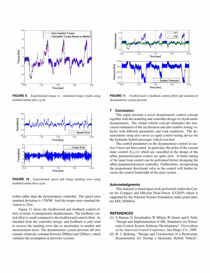
FIGURE 9. Experimental torque vs. simulated torque results usingmodified urban drive cycle
FIGURE 10. Experimental speed and torque tracking error usingmodified urban drive cycle
troller rather than the dynamometer controller. The speed errorstandard deviation is 17RPM. And the torque error standard de-viation is 2Nm.
Figure 11 shows the feedforward and feedback control ef-forts in terms of pump/motor displacements. The feedback con-trol effort is small compared to the feedforward control effort. Asintended from the controller design, and feedback is only usedto recover the tracking error due to uncertainty in models andmeasurement noise. The dynamometer system pressure ∆P alsoremains relatively constant between 2000psi and 2200psi, whichvalidates the assumption in previous sections.
FIGURE 11. Feedforward vs feedback control effort and variation ofdynamometer system pressure
7 ConclusionThis paper presents a novel dynamometer control concept
together with the modeling and controller design of a hydrostaticdynamometer. The virtual vehicle concept eliminates the non-causal estimation of the acceleration and also enables testing ve-hicles with different parameters and road conditions. The dy-namometer setup also serves as rapid control testing device forthe hydraulic hybrid passenger vehicle test-bed.
The control parameters in the dynamometer control in sec-tion 5 have not been tuned. In particular, the poles of the currentinner control (Gp(s)) which are cancelled in the design of theaffine parameterization control are quite slow. A better tuningof the inner loop control can be performed before designing theaffine parametermization controller. Furthermore, incorporatingthe proportional directional valve in the control will further in-crease the control bandwidth of the dyno system.
AcknowledgmentsThis material is based upon work performed within the Cen-
ter for Compact and Efficient Fluid Power (CCEFP) which issupported by the National Science Foundation under grant num-ber EEC-0540834.
REFERENCES[1] S. Raman, N. Sivashankar, W. Milam, W. Stuart, and S. Nabi,
“Design and Implementation of HIL Simulators for Power-train Control System Software Development,” Proceedingsof the American Control Conference, San Diego, CA, 1999
[2] H. J. Kohring, “Design and Construction of a HydrostaticDynamometer for Testing a Hydraulic Hybrid Vehicle”,
M.S.-A Thesis, Department of Mechanical Engineering,University of Minnesota, Twin Cities, 2012.
[3] J.-S. Chen, “Speed and Acceleration Filters/Estimators forPowertrain and Vehicle Controls,” SAE Technical paper,2007-1-1599, April 2007
[4] J. Longstreth, F. Sanders, S. Seaney, J. Moskwa et. al.“Design and Construction of a High-Bandwidth HydrostaticDynamometer,” SAE Technical Paper 930259, 1993, DOI:10.4271/930259.
[5] J. Lahti and J. Moskwa, “A Transient Test System for Sin-gle Cylinder Research Engines with Real Time Simula-tion of Multi-Cylinder Crankshaft and Intake Manifold Dy-namics”, SAE Technical Paper, 2004-01-305, 2004, DOI:10.4271/2004-01-0305.
[6] A. S. Heisler, J. Moskwa and F. Fronczak, “The Designof Low-Inertia, High-Speed External Gear Pump/motors forHydrostatic Dynamometer Systems”, SAE Technical Paper2009-01-1117, 2009.
[7] M. Holland, K. Harmeyer and J. Lumkes Jr., “Design of aHigh-Bandwidth, Low-cost Hydrostatic Dynamometer withElectronic Load Control”, SAE Tecnnical Paper: 2009-01-2846.
[8] F. Tavaresm, R. Johri, and A. Salvi, “Hydraulic HybridPowertrain-in-the-loop integration for analyzing real-worldfuel economy and emissions improvements”, SAE Techni-cal Paper 2011-01-2275, 2011. DOI:10.4271/2011-01-2275.
[9] Y. Wang, Z. Sun, and K. A. Stelson, Kim, “Modeling, Con-trol, and Experimental Validation of a Transient Hydro-static Dynamometer,” IEEE Transactions on Control Sys-tems Technology, volume 19, number 6, Nov. 2011
[10] I. Stringer, and K. Bullock, ”A Regenerative RoadLoad Simulator,” SAE Technical Paper 845115, 1984,doi:10.4271/845115.
[11] R. Zhang, and A. G. Alleyne, “Dynamic Emulation Usingan Indirect Control Input,” ASME Journal of Dynamic Sys-tems, Measurement, and Control, 127:1, pp.114-124, 2005
[12] J.D. Van de Ven, M.W. Olson and P.Y. Li, “Developmentof a hydro-mechanical hydraulic hybrid drive train with in-dependent wheel torque control for an urban passenger vehi-cle,” in Proceedings of the 2008 International Fluid PowerExposition (IFPE), Las Vegas, NV, 2008.
[13] G. C. Goodwin, S. F. Graebe, M. E. Salgado Control SystemDesign. Prentice Hall 2000.
[14] P. Y. Li and F. Mensing, “Optimization and Control ofa Hydro-Mechanical Transmission Based Hydraulic HybridPassenger Vehicle”, 7th International Fluid Power Confer-ence (IFK), Aachen, Germany, March, 2010.
[15] K. L. Cheong, Z. Du, P. Y. LI and T. R. Chase, “HierarchicalControl Strategy for a Hybrid Hydro-mechanical transmis-sion (HMT) powr-train”, Proceedings of the 2014 AmericanControl Conference, Portland, OR, June 2014.