Embed Size (px)
Citation preview
D13.deSystem Data Sheet
Drywall Systems
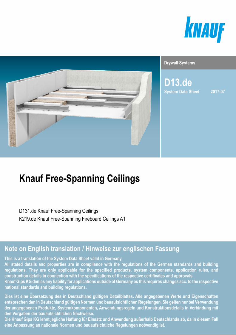
Knauf Free-Spanning Ceilings
D131.de Knauf Free-Spanning CeilingsK219.de Knauf Free-Spanning Fireboard Ceilings A1
2017-07
Note on English translation / Hinweise zur englischen FassungThis is a translation of the System Data Sheet valid in Germany. All stated details and properties are in compliance with the regulations of the German standards and building regulations. They are only applicable for the specified products, system components, application rules, and construction details in connection with the specifications of the respective certificates and approvals.Knauf Gips KG denies any liability for applications outside of Germany as this requires changes acc. to the respective national standards and building regulations.
Dies ist eine Übersetzung des in Deutschland gültigen Detailblattes. Alle angegebenen Werte und Eigenschaften entsprechen den in Deutschland gültigen Normen und bauaufsichtlichen Regelungen. Sie gelten nur bei Verwendung der angegebenen Produkte, Systemkomponenten, Anwendungsregeln und Konstruktionsdetails in Verbindung mit den Vorgaben der bauaufsichtlichen Nachweise.Die Knauf Gips KG lehnt jegliche Haftung für Einsatz und Anwendung außerhalb Deutschlands ab, da in diesem Fall eine Anpassung an nationale Normen und bauaufsichtliche Regelungen notwendig ist.
2 D13.de Knauf Free-Spanning Ceilings
ContentsIntroduction
Usage instructions I General instructions ............................................................................................................................ 4
Certificate of usability ............................................................................................................................................................ 5
System overview .................................................................................................................................................................... 6
Data for planningD131.de Technical and physical building data ..................................................................................................................... 8
Without fire resistance .................................................................................................................................................................8Fire protection F30 solely from below .......................................................................................................................................10Fire resistance F30 solely from below and from above (plenum)..............................................................................................12Fire resistance F60 solely from below and from above (plenum)..............................................................................................14
K219.de Technical and physical building data ................................................................................................................... 16
Fire protection F90 solely from below .......................................................................................................................................16Fire resistance F90 solely from below and from above (plenum)..............................................................................................18
Airborne and impact sound insulation ............................................................................................................................... 20
Permissible furring channel spacings ................................................................................................................................ 22
Anchoring of loads ............................................................................................................................................................... 23
Construction detailsD131.de without fire resistance ........................................................................................................................................... 24
D131.de F30 solely from below............................................................................................................................................ 26
D131.de F30 solely from below and from above ................................................................................................................ 28
D131.de F60 solely from below and from above ................................................................................................................ 30
K219.de F90 solely from below............................................................................................................................................ 32
K219.de F90 solely from below and from above ................................................................................................................ 34
Special details ...................................................................................................................................................................... 36
Special versionsT connection and L connection ........................................................................................................................................... 44
Simplified procedure .................................................................................................................................................................44Exact procedure ........................................................................................................................................................................45
Metal traverse ....................................................................................................................................................................... 52
Centre suspension ............................................................................................................................................................... 53
Multi-Level Ceiling System .................................................................................................................................................. 54

3D13.de Knauf Free-Spanning Ceilings
Installation and applicationGrid ................................................................................................................................................................................................58
CW furring channels ..................................................................................................................................................................58UA furring channels ...................................................................................................................................................................59Connection to wall with furring channels CW ............................................................................................................................60Connection to wall with furring channels UA .............................................................................................................................62
Insulation layer I Top side covering layer I Cladding ................................................................................................................64Cladding ........................................................................................................................................................................................65Jointing ..........................................................................................................................................................................................66Coatings and linings ....................................................................................................................................................................67
Material requirementKnauf Free-Spanning Ceilings D131.de ......................................................................................................................................68Knauf Free-Spanning Ceilings K219.de ......................................................................................................................................70
Information on sustainabilityKnauf Free-Spanning Ceilings ....................................................................................................................................................72

4 D13.de Knauf Free-Spanning Ceilings
IntroductionUsage instructions I General instructions
Usage instructionsNotes on the documentKnauf System Data Sheets are the planning and application basis for the planners and professional installers with the application of Knauf systems. The contained information and specifications, constructions, details and stated products are based, unless otherwise stated, on the certificates of usability (e.g. National Technical Test Certificate (abP) and/or German National Technical Approvals (abZ)) valid at the date they are published as well as on the applicable standards. Additionally, design and structural requirements and those relating to building physics (fire resistance and sound insulation) are considered. The contained construction details are examples and can be used in a similar way for various cladding variants of the respective system. At the same time, the demands made on fire resistance and/or sound insulation as well as any necessary additional measures and/or limitations must be observed.
References to other documents ■ Free-spanning ceilings with increased span widths see Technical Information Tro143.de “Knauf Free-Spanning Ceilings”
■ Suspended ceilings linings and suspended ceilings see System Data Sheet D11.de “Knauf Board Ceilings”
■ Board ceilings and free-spanning suspended ceilings under wooden batten ceilings (basic ceilings of building type IV), see System Data Sheet D15.de “Knauf Holzbalkendecken-Systeme” (German only)
■ Acoustic board ceilings, see System Data Sheet D12.de “Knauf Acoustic Board Ceilings”
■ Observe the Product Data Sheets of the Knauf system components
Symbols in System Data SheetThe following symbols are used in this document:
G Mineral wool insulation layer acc. to EN 13162 non-combustible (insulating material, e.g. from Knauf Insulation)
S Mineral wool insulation layer acc. to EN 13162 non-combustible melting point ≥ 1000 °C acc. to DIN 4102-17 (insulating material, e.g. from Knauf Insulation)
b Axial spacing furring channel (cladding span width)
Intended use of Knauf systemsPlease observe the following:
Caution
Knauf systems may only be used for the application cases as stated in the Knauf documentation. In case third-party products or components are used, they must be recommended or approved by Knauf. Flawless application of products/systems assumes proper transport, storage, assembly, installation and maintenance.
General instructionsDefinition of termsKnauf Free-Spanning Ceilings are applied as suspended ceilings. The following definition applies acc. to DIN 18168-1: Suspended ceilings are: “… ceilings of even or other design with smooth, perforated or jointed surface consisting of a substructure and a surface layer forming the area …”.The connection of the ceiling described as “free-spanning” is the support for the freely-supporting furring channel, implemented as UW perimeter runners or UA profiles using Knauf connection angles and connection brackets.The connection described as “constructive” is the perimeter connection to the furring channels.
Field of applicationKnauf Free-Spanning Ceilings are used
■ In interiors as suspended ceilings under the solid ceiling, wood joist ceilings and trapezoid sheet metal ceilings for improving the fire resistance, sound insulation or thermal protection, for manufacturing a completely free installation level between the basic ceiling and the exposed ceiling as well as for regulating the room height.
■ In exterior areas not directly exposed to the weather under specific circumstances, such as with a corrosion-proofed grid and suitable boards, e.g. Knauf Drystar Board. A preliminary dimensioning of the grid / wood frame taking the demands that apply in exterior areas into consideration (pressure / suction) can be undertaken on request.
Fire resistance effectIf the fire resistance effect from the classification of Knauf Board Ceiling is achieved without involvement or consideration of the basic ceiling, the fire resistance is referred to as solely.This is relevant in particular when the plenum is to be protected against the exposure to fire from the room (fire resistance solely from below) or a protective effect for the room against fire exposure from the plenum (fire resistance solely from above).A combination of both requirements may be necessary depending on the requirements stipulated by the building inspectorate and/or fire resistance concept.
Movement jointsMovement joints have to be transferred into the construction of the Free-Spanning Ceilings. Use control joints in the case of ceiling areas exceeding approx. 15 m in length, e.g. for narrow ceiling spaces caused by a break of a wall. Separate connections of boards to components made of a different building material, especially columns, or thermally highly stressed built-ins such as lighting fixtures, for instance with shadow gaps.
5D13.de Knauf Free-Spanning Ceilings
IntroductionCertificate of usability
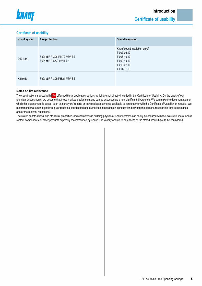
Certificate of usability
Notes on fire resistanceThe specifications marked with offer additional application options, which are not directly included in the Certificate of Usability. On the basis of our technical assessments, we assume that these marked design solutions can be assessed as a non-significant divergence. We can make the documentation on which this assessment is based, such as surveyors' reports or technical assessments, available to you together with the Certificate of Usability on request. We recommend that a non-significant divergence be coordinated and authorised in advance in consultation between the persons responsible for fire resistance and/or the relevant authorities.The stated constructional and structural properties, and characteristic building physics of Knauf systems can solely be ensured with the exclusive use of Knauf system components, or other products expressly recommended by Knauf. The validity and up-to-datedness of the stated proofs have to be considered.
Knauf system Fire protection Sound insulation
D131.de F30: abP P-3964/2172-MPA BS F60: abP P-SAC 02/III-511
Knauf sound insulation proof T 007-06.10 T 008-10.10 T 009-10.10 T 010-07.10 T 011-07.10
K219.de F90: abP P-3085/3824-MPA BS

6 D13.de Knauf Free-Spanning Ceilings
IntroductionSystem overview
Knauf Free-Spanning CeilingsKnauf Free-Spanning Ceilings are attached exclusively as suspended ceilings anchored to the surrounding walls. Knauf boards are fastened to a metal substructure grid made of Knauf CW/UA profiles as single or double profiles.
D131.de Knauf Free-Spanning Ceiling Without fire resistance
D131.de Knauf Free-Spanning CeilingFire resistance F30 solely from below
D131.de Knauf Free-Spanning Ceiling Fire resistance F30 solely from below and from above
D131.de Knauf Free-Spanning Ceiling Fire resistance F60 solely from below and from above
Knauf boards are fixed with screws to a metal grid of free-spanningfurring channels made of single or double CW or UA profiles. The furring channels are anchored only to the flanking walls. An sound insulation effective insulation layer can be laid between the furring channels (upon the cladding).Depending on the system variants selected, room widths (span widths) up to 6.00 m are possible.
Knauf boards are fixed with screws to a metal grid of free-spanningfurring channels made of double CW or UA profiles. The furring channels are anchored only to the flanking walls. A system variant dependent effective fire resistance and/or sound insulation layer is laid between the furring channels (upon the cladding).Depending on the system variants selected, room widths (span widths) up to 5.45 m are possible.
Knauf boards are fixed with screws to a metal grid of free-spanningfurring channels made of single or double CW or UA profiles with additional covering strips. The furring channels are anchored only to the flanking walls. A fire resistance and sound insulation effective insulation layer is laid between the furring channels (upon the cladding).Depending on the system variants selected, room widths (span widths) up to 4.80 m are possible.
Knauf boards are fixed with screws to a metal grid of free-spanningfurring channels made of single or double CW or UA profiles with additional covering strips. The furring channels are anchored only to the flanking walls. A top side covering layer made of gypsum boards is obligatory for fire resistance reasons. A fire resistance and sound insulation effective insulation layer is laid between the furring channels (upon the cladding).Depending on the system variants selected, room widths (span widths) up to 4.20 m are possible.

7D13.de Knauf Free-Spanning Ceilings
IntroductionSystem overview
K219.de Knauf Free-Spanning Fireboard Ceiling A1 Fire resistance F90 solely from below
K219.de Knauf Free-Spanning Fireboard Ceiling A1Fire resistance F90 solely from below and from above
Knauf Fireboards are fixed with screws to a metal grid of free-spanningfurring channels made of double CW or UA profiles. The furring channels are anchored only to the flanking walls. A system variant dependent effective sound insulation layer is laid between the furring channels (upon the cladding).Depending on the system variants selected, room widths (span widths) up to 4.95 m are possible.
Knauf Fireboards are fixed with screws to a metal grid of free-spanningfurring channels made of double CW or UA profiles with additional covering strips. The furring channels are anchored only to the flanking walls. A top side covering layer made of Fireboard is obligatory for fire resistance reasons. A fire resistance and sound insulation effective insulation layer is laid between the furring channels (upon the cladding).Depending on the system variants selected, room widths (span widths) up to 4.35 m are possible.

8 D13.de Knauf Free-Spanning Ceilings
Data for planningD131.de Technical and physical building data
Without fire resistanceFireresistance class
Cladding (lateral application) Furring channel Insulation layer
Knau
f Bau
plat
te W
allbo
ard
Knau
f Pian
o fir
e-re
sista
nt b
oard
Knau
f fire
-resis
tant
boa
rd
Diam
ant
Silen
tboa
rd
Max. axial clearancesb
Required for fire resistance
With fire exposure
Minimum thickness
CW/UA profile Minimum thickness
Minimumdensity
Single profile
Double profile
From below
From above mm mm kg/m³mm mm
D131.de Knauf Free-Spanning Ceiling
– –
● 12.5 500 500
–
● 12.5 – 500
● 15 – 500
● 2x 12.5 – 500
● 12.5 – 400
●
● 12.5+12.5
– 400
With combined cladding always use Diamant as a cover layer
e.g. CW single profile
e.g. CW double profile
Permissible connections to wallFree-Spanning Ceilings D131.de without fire resistance can be connected to the supporting connection as well as to the structural connection on the solid walls and lightweight partitions (metal stud partitions).
Note Observe the notes on page 4.

b
Max. room width
9D13.de Knauf Free-Spanning Ceilings
Data for planningD131.de Technical and physical building data
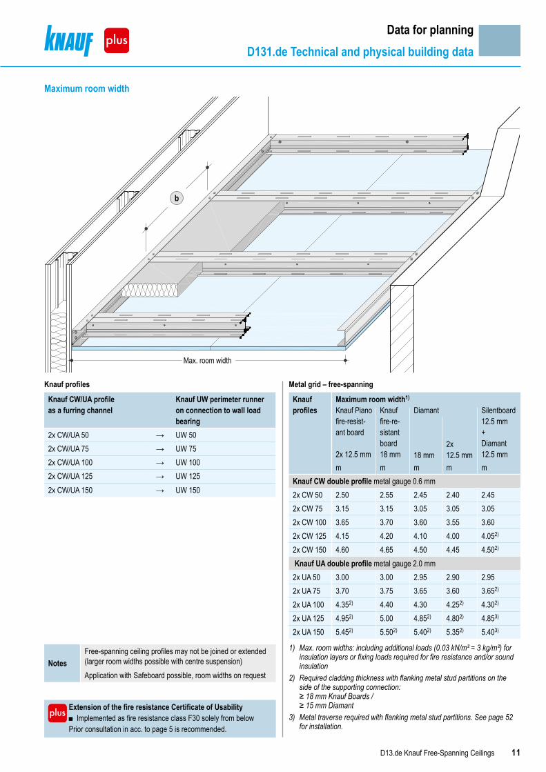
NotesLarger room widths possible on request.Free-spanning ceiling profiles may not be joined or extended (larger room widths possible with centre suspension)
Maximum room width
Metal grid – free-spanning, double profile
Knauf profiles
Maximum room width1)
Knauf Bauplatte Wallboard
Diamant Silentboard Silentboard 12.5 mm
12.5 mm 12.5 mm 15 mm 2x 12.5 mm 12.5 mm + Diamant 12.5 mmm m m m m m
CW double profile metal gauge 0.6 mm2x CW 50 2.90 2.75 2.65 2.40 2.70 2.452x CW 75 3.60 3.45 3.35 3.05 3.40 3.052x CW 100 4.25 4.05 3.90 3.55 3.95 3.602x CW 125 4.80 4.55 4.40 4.00 4.50 4.052)
2x CW 150 5.30 5.05 4.90 4.45 4.95 4.502)
UA double profile metal gauge 2.0 mm2x UA 50 3.35 3.25 3.15 2.90 3.20 2.952x UA 75 4.15 4.00 3.90 3.60 3.95 3.652)
2x UA 100 4.85 4.70 4.60 4.252) 4.652) 4.302)
2x UA 125 5.45 5.30 5.152) 4.802) 5.252) 4.853)
2x UA 150 6.002) 5.852) 5.702) 5.353) 5.803) 5.403)
Metal grid – free-spanning, single profile
Knauf profile Max. room width1)
Knauf Bauplatte Wallboard 12.5 mmm
CW single profile metal gauge 0.6 mmCW 50 2.50CW 75 3.15CW 100 3.65CW 125 4.15CW 150 4.60UA single profile metal gauge 2.0 mmUA 50 3.00UA 75 3.70UA 100 4.35UA 125 4.95UA 150 5.45
Knauf profiles
Knauf CW/UA profile as the furring channel
Knauf UW perimeter runner on connection to wall load bearing
(2x) CW/UA 50 → UW 50(2x) CW/UA 75 → UW 75(2x) CW/UA 100 → UW 100(2x) CW/UA 125 → UW 125(2x) CW/UA 150 → UW 150
1) Max. room widths: Including additional loads (0.03 kN/m² = 3 kg/m²) for insulation layers necessary for sound insulation measures and/or fixing loads.
2) Required cladding thickness with flanking metal stud partitions on the side of the supporting connection: ≥ 18 mm Knauf Boards / ≥ 15 mm Diamant
3) Metal traverse required with flanking metal stud partitions. See page 52 for installation.
10 D13.de Knauf Free-Spanning Ceilings
Data for planningD131.de Technical and physical building data
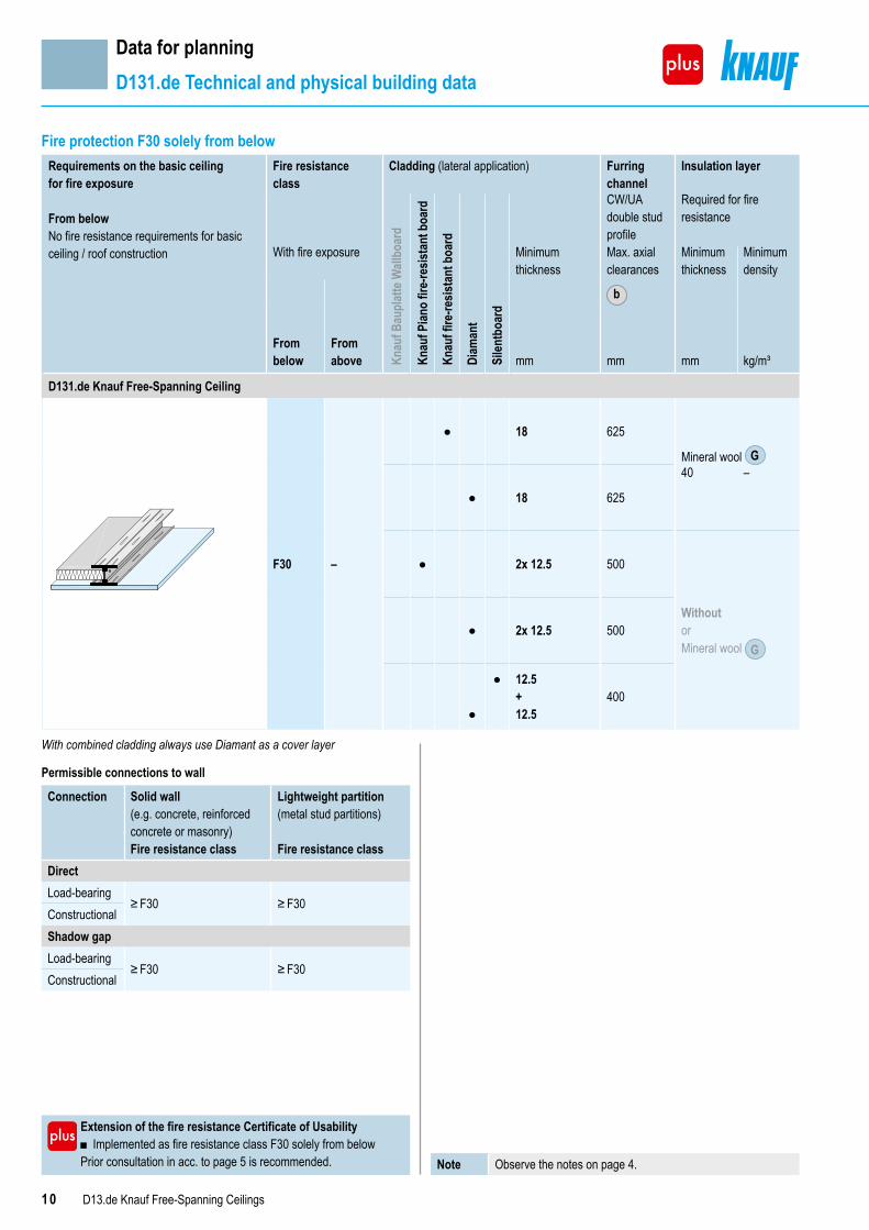
Fire protection F30 solely from belowRequirements on the basic ceilingfor fire exposure
From belowNo fire resistance requirements for basic ceiling / roof construction
Fire resistance class
Cladding (lateral application) Furring channel
Insulation layer
Knau
f Bau
plat
te W
allbo
ard
Knau
f Pian
o fir
e-re
sista
nt b
oard
Knau
f fire
-resis
tant
boa
rd
Diam
ant
Silen
tboa
rd
CW/UA double stud profile
Required for fire resistance
With fire exposure Minimum thickness
Max. axial clearances
b
Minimum thickness
Minimumdensity
From below
From above mm mm mm kg/m³
D131.de Knauf Free-Spanning Ceiling
F30 –
● 18 625
Mineral wool G
● 18 625
40 –
● 2x 12.5 500
Without orMineral wool G
● 2x 12.5 500
●
● 12.5+12.5
400
With combined cladding always use Diamant as a cover layer
Permissible connections to wall
Connection Solid wall (e.g. concrete, reinforced concrete or masonry)
Lightweight partition (metal stud partitions)
Fire resistance class Fire resistance classDirectLoad-bearing
≥ F30 ≥ F30ConstructionalShadow gapLoad-bearing
≥ F30 ≥ F30Constructional
Note Observe the notes on page 4.
Extension of the fire resistance Certificate of Usability ■ Implemented as fire resistance class F30 solely from below
Prior consultation in acc. to page 5 is recommended.
b
Max. room width
11D13.de Knauf Free-Spanning Ceilings
Data for planningD131.de Technical and physical building data
NotesFree-spanning ceiling profiles may not be joined or extended (larger room widths possible with centre suspension)Application with Safeboard possible, room widths on request
Maximum room width
Extension of the fire resistance Certificate of Usability ■ Implemented as fire resistance class F30 solely from below
Prior consultation in acc. to page 5 is recommended.
Metal grid – free-spanning
Knauf profiles
Maximum room width1)
Knauf Piano fire-resist-ant board 2x 12.5 mm
Knauf fire-re-sistant board 18 mm
Diamant Silentboard12.5 mm+ Diamant12.5 mm18 mm
2x12.5 mm
m m m m mKnauf CW double profile metal gauge 0.6 mm2x CW 50 2.50 2.55 2.45 2.40 2.452x CW 75 3.15 3.15 3.05 3.05 3.052x CW 100 3.65 3.70 3.60 3.55 3.602x CW 125 4.15 4.20 4.10 4.00 4.052)
2x CW 150 4.60 4.65 4.50 4.45 4.502)
Knauf UA double profile metal gauge 2.0 mm 2x UA 50 3.00 3.00 2.95 2.90 2.952x UA 75 3.70 3.75 3.65 3.60 3.652)
2x UA 100 4.352) 4.40 4.30 4.252) 4.302)
2x UA 125 4.952) 5.00 4.852) 4.802) 4.853)
2x UA 150 5.452) 5.502) 5.402) 5.352) 5.403)
1) Max. room widths: including additional loads (0.03 kN/m² = 3 kg/m²) for insulation layers or fixing loads required for fire resistance and/or sound insulation
2) Required cladding thickness with flanking metal stud partitions on the side of the supporting connection: ≥ 18 mm Knauf Boards / ≥ 15 mm Diamant
3) Metal traverse required with flanking metal stud partitions. See page 52 for installation.
Knauf profiles
Knauf CW/UA profile as a furring channel
Knauf UW perimeter runner on connection to wall load bearing
2x CW/UA 50 → UW 502x CW/UA 75 → UW 752x CW/UA 100 → UW 1002x CW/UA 125 → UW 1252x CW/UA 150 → UW 150

12 D13.de Knauf Free-Spanning Ceilings
Data for planningD131.de Technical and physical building data
Fire resistance F30 solely from below and from above (plenum)Requirements on the basic ceilingfor fire exposure
From belowNo fire resistance requirements for basic ceiling / roof construction
From above (Plenum)Raw ceiling must have same fire resistance class as suspended ceiling
Fireresistance class
Cladding (lateral application) Furring channel
Insulation layer
Knau
f Bau
plat
te W
allbo
ard
Knau
f Pian
o fir
e-re
sista
nt b
oard
Knau
f fire
-resis
tant
boa
rd
Diam
ant
Silen
tboa
rd
CW/UA double stud profile
Required for fire resistance
With fire exposure Minimum thickness
Max. axial clearances
b
Minimum thickness
Minimumdensity
From below
From above mm mm mm kg/m³
D131.de Knauf Free-Spanning CeilingCovering strips25 mm Massivbauplatte Solid Board
F30 F30
● 18 625
● 18 625Mineral wool S
● 2x 12.5 500
60 30Alternative
Mineral wool S 40 40
● 2x 12.5 500
●
● 12.5+ 12.5
400
With combined cladding always use Diamant as a cover layer
Note Observe the notes on page 4.
Extension of the fire resistance Certificate of Usability ■ Cladding with 2x 12.5 mm ■ Connection to lightweight partition ■ Connection to walls with shadow gaps ■ When using mineral wool S thickness 40 mm, density 40 kg/m³
Prior consultation in acc. to page 5 is recommended.
Permissible connections to wall
Connection Solid wall (e.g. concrete, reinforced concrete or masonry)
Lightweight partition (metal stud partitions)
Fire resistance class Fire resistance classDirectLoad-bearing
≥ F30 ≥ F30
Constructional ≥ F30Shadow gapLoad-bearing ≥ F30
≥ F30Constructional ≥ F30

b
Max. room width
13D13.de Knauf Free-Spanning Ceilings
Data for planningD131.de Technical and physical building data
Knauf profiles
Knauf CW/UA profile as a furring channel
Knauf UW perimeter runner on connection to wall load bearing
2x CW/UA 50 → UW 752x CW/UA 75 → UW 1002x CW/UA 100 → UW 1252x CW/UA 125 → UW 150
Metal grid – free-spanning
Knauf profiles
Maximum room width1)
Knauf Piano fire-resist-ant board
2x12.5 mm
Knauf Feuer-schutzplatte fire-resistant board
18 mm
Diamant Silent-board 12.5 mm+ Diamant12.5 mm
18 mm 2x12.5mm
m m m m m m mKnauf CW double profile metal gauge 0.6 mm2x CW 50 2.30 – 2.35 – 2.20 2.15 2.202x CW 75 2.90 3.00 3.00 2.80 2.80 2.75 2.802x CW 100 3.45 3.00 3.50 3.00 3.35 3.25 3.302x CW 125 3.95 3.00 4.05 3.00 3.85 3.75 3.802)
Knauf UA double profile metal gauge 2.0 mm 2x UA 50 2.90 – 2.90 – 2.85 2.80 2.852x UA 75 3.55 – 3.60 – 3.50 3.50 3.502)
2x UA 100 4.202) – 4.25 – 4.15 4.102) 4.153)
2x UA 125 4.802) – 4.802) – 4.702) 4.653) 4.703)
1) Max. room widths: including additional loads (0.03 kN/m² = 3 kg/m²) for insu-lation layers or fixing loads required for fire resistance and/or sound insulation
2) Required cladding thickness with flanking metal stud partitions on the side of the supporting connection: ≥ 18 mm Knauf Boards / ≥ 15 mm Diamant
3) Metal traverse required with flanking metal stud partitions. See page 52 for installation.
Extension of the fire resistance Certificate of Usability ■ Extended maximum room widths ■ Cladding with 2x 12.5 mm ■ Implemented with UA profiles
Prior consultation in acc. to page 5 is recommended.
Maximum room width
Note Free-spanning ceiling profiles may not be joined or extended (larger room widths possible with centre suspension)
14 D13.de Knauf Free-Spanning Ceilings
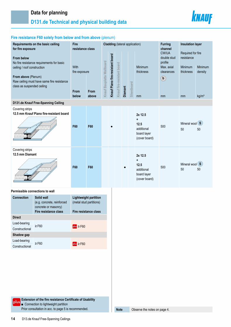
Data for planningD131.de Technical and physical building data
Requirements on the basic ceilingfor fire exposure
From belowNo fire resistance requirements for basic ceiling / roof construction
From above (Plenum)Raw ceiling must have same fire resistance class as suspended ceiling
Fireresistance class
Cladding (lateral application) Furring channel
Insulation layer
Knau
f Bau
plat
te W
allbo
ard
Knau
f Pian
o fir
e-re
sista
nt b
oard
Knau
f fire
-resis
tant
boa
rd
Diam
ant
Silen
tboa
rd
CW/UA double stud profile
Required for fire resistance
With fire exposure
Minimum thickness
Max. axial clearances
b
Minimum thickness
Minimumdensity
From below
From above mm mm mm kg/m³
D131.de Knauf Free-Spanning CeilingCovering strips12.5 mm Knauf Piano fire-resistant board
F60 F60 ●
2x 12.5+12.5additionalboard layer(cover board)
500Mineral wool S50 50
Covering strips12.5 mm Diamant
F60 F60 ●
2x 12.5+12.5additionalboard layer(cover board)
500Mineral wool S50 50
Fire resistance F60 solely from below and from above (plenum)
Permissible connections to wall
Connection Solid wall (e.g. concrete, reinforced concrete or masonry)
Lightweight partition (metal stud partitions)
Fire resistance class Fire resistance classDirectLoad-bearing
≥ F60 ≥ F60ConstructionalShadow gapLoad-bearing
≥ F60 ≥ F60Constructional
Extension of the fire resistance Certificate of Usability ■ Connection to lightweight partition
Prior consultation in acc. to page 5 is recommended. Note Observe the notes on page 4.

15D13.de Knauf Free-Spanning Ceilings
Data for planningD131.de Technical and physical building data
b
Max. room width
Knauf profiles
Knauf CW/UA profile as a furring channel
Knauf UW perimeter runner on connection to wall load bearing
2x CW/UA 50 → UW 502x CW/UA 75 → UW 752x CW/UA 100 → UW 1002x CW/UA 125 → UW 1252x CW/UA 150 → UW 150
Metal grid – free-spanning
Knauf profiles Maximum room width1)
Knauf Piano fire- resistant board 2x 12.5 mmm
Diamant
2x 12.5 mmm
Knauf CW double profile metal gauge 0.6 mm2x CW 50 2.25 2.202x CW 75 2.85 2.752x CW 100 3.35 3.202)
2x CW 125 3.802) 3.652)
2x CW 150 4.202) 4.052)
Knauf UA double profile metal gauge 2.0 mm 2x UA 50 2.75 2.652x UA 75 3.402) 3.302)
2x UA 100 4.052) 3.903)
2x UA 125 4.603) 4.453)
2x UA 150 5.103) 4.953)
1) Max. room widths: including additional loads (0.03 kN/m² = 3 kg/m²) for insulation layers or fixing loads required for fire resistance and/or sound insulation
2) Required cladding thickness with flanking metal stud partitions on the side of the supporting connection: ≥ 18 mm Knauf Boards / ≥ 15 mm Diamant
3) Metal traverse required with flanking metal stud partitions. See page 52 for installation.
Maximum room width
Extension of the fire resistance Certificate of Usability ■ Implemented with double profile CW 50 / 75 / 100 / 125 ■ Implemented with UA profiles
Prior consultation in acc. to page 5 is recommended.
Note Free-spanning ceiling profiles may not be joined or extended.
16 D13.de Knauf Free-Spanning Ceilings
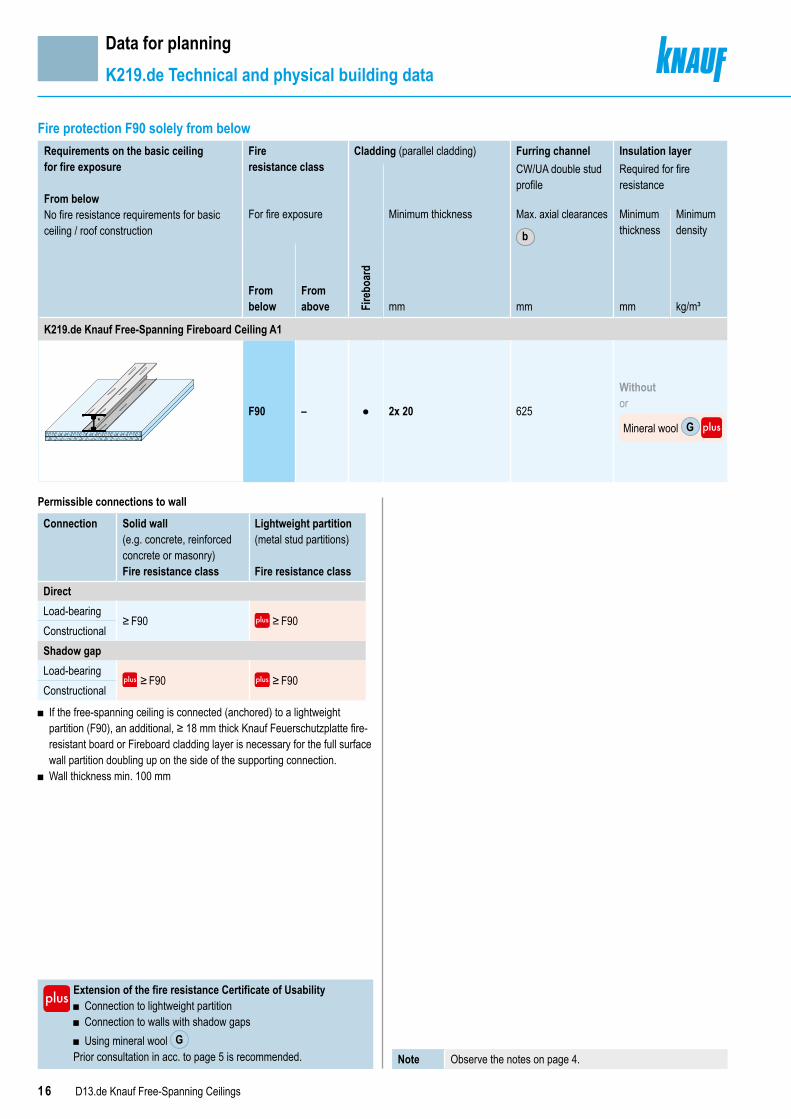
Data for planningK219.de Technical and physical building data
Requirements on the basic ceilingfor fire exposure
From belowNo fire resistance requirements for basic ceiling / roof construction
Fireresistance class
Cladding (parallel cladding) Furring channel Insulation layer
Fire
boar
d
CW/UA double stud profile
Required for fire resistance
For fire exposure Minimum thickness Max. axial clearances
b
Minimum thickness
Minimumdensity
From below
From above mm mm mm kg/m³
K219.de Knauf Free-Spanning Fireboard Ceiling A1
F90 – ● 2x 20 625
Without or
Mineral wool G
Fire protection F90 solely from below
Permissible connections to wall
Connection Solid wall (e.g. concrete, reinforced concrete or masonry)
Lightweight partition (metal stud partitions)
Fire resistance class Fire resistance classDirectLoad-bearing
≥ F90 ≥ F90ConstructionalShadow gapLoad-bearing
≥ F90 ≥ F90Constructional
■ If the free-spanning ceiling is connected (anchored) to a lightweight partition (F90), an additional, ≥ 18 mm thick Knauf Feuerschutzplatte fire-resistant board or Fireboard cladding layer is necessary for the full surface wall partition doubling up on the side of the supporting connection.
■ Wall thickness min. 100 mm
Extension of the fire resistance Certificate of Usability ■ Connection to lightweight partition ■ Connection to walls with shadow gaps ■ Using mineral wool G
Prior consultation in acc. to page 5 is recommended. Note Observe the notes on page 4.
17D13.de Knauf Free-Spanning Ceilings
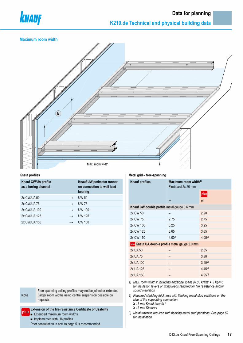
Data for planningK219.de Technical and physical building data
Max. room width
b
Knauf profiles
Knauf CW/UA profile as a furring channel
Knauf UW perimeter runner on connection to wall load bearing
2x CW/UA 50 → UW 502x CW/UA 75 → UW 752x CW/UA 100 → UW 1002x CW/UA 125 → UW 1252x CW/UA 150 → UW 150
Extension of the fire resistance Certificate of Usability ■ Extended maximum room widths ■ Implemented with UA profiles
Prior consultation in acc. to page 5 is recommended.
Metal grid – free-spanning
Knauf profiles Maximum room width1)
Fireboard 2x 20 mm
m mKnauf CW double profile metal gauge 0.6 mm2x CW 50 – 2.202x CW 75 2.75 2.752x CW 100 3.25 3.252x CW 125 3.65 3.652x CW 150 4.002) 4.052)
Knauf UA double profile metal gauge 2.0 mm 2x UA 50 – 2.652x UA 75 – 3.302x UA 100 – 3.902)
2x UA 125 – 4.452)
2x UA 150 – 4.953)
1) Max. room widths: Including additional loads (0.03 kN/m² = 3 kg/m²) for insulation layers or fixing loads required for fire resistance and/or sound insulation
2) Required cladding thickness with flanking metal stud partitions on the side of the supporting connection: ≥ 18 mm Knauf boards / ≥ 15 mm Diamant
3) Metal traverse required with flanking metal stud partitions. See page 52 for installation.
Maximum room width
NoteFree-spanning ceiling profiles may not be joined or extended (larger room widths using centre suspension possible on request).

18 D13.de Knauf Free-Spanning Ceilings
Data for planningK219.de Technical and physical building data
Requirements on the basic ceilingfor fire exposure
From belowNo fire resistance requirements for basic ceiling / roof construction
From above (Plenum)Raw ceiling must have same fire resistance class as suspended ceiling
Fireresistance class
Cladding (parallel cladding) Furring channel Insulation layer
Fire
boar
d
CW/UA double stud profile
Required for fire resistance
With fire exposure
Minimum thickness Max. axial clearances
b
Minimum thickness
Minimumdensity
From below
From above mm mm mm kg/m³
K219.de Knauf Free-Spanning Fireboard Ceiling A1
Covering strips 12.5 mm Fireboard
e.g. CW furring channelF90 F90 ●
20+20additionalboard layer(cover board)
625 Mineral wool S
e.g. CW furring channel
60 50
Fire resistance F90 solely from below and from above (plenum)
Permissible connections to wall
Connection Solid wall (e.g. concrete, reinforced concrete or masonry)
Lightweight partition (metal stud partitions)
Fire resistance class Fire resistance classDirectLoad-bearing
≥ F90 ≥ F90ConstructionalShadow gapLoad-bearing ≥ F90
≥ F90Constructional ≥ F90
■ If the free-spanning ceiling is connected (anchored) to a lightweight partition (F90), an additional, ≥ 18 mm thick Knauf Feuerschutzplatte fire-resistant board or Fireboard cladding layer is necessary for the full surface wall partition doubling up on the side of the supporting connection. Under the doubling up a Flex Profile should be inserted at the level of the connection to the ceiling.
■ Wall thickness min. 100 mm
Extension of the fire resistance Certificate of Usability ■ Connection to walls with shadow gaps
Prior consultation in acc. to page 5 is recommended. Note Observe the notes on page 4.
19D13.de Knauf Free-Spanning Ceilings
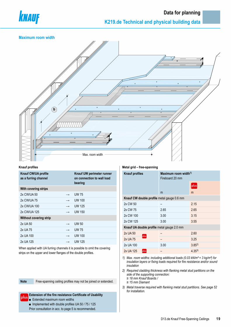
Data for planningK219.de Technical and physical building data
Max. room width
b
Knauf profiles
Knauf CW/UA profile as a furring channel
Knauf UW perimeter runner on connection to wall load bearing
With covering strips2x CW/UA 50 → UW 752x CW/UA 75 → UW 1002x CW/UA 100 → UW 1252x CW/UA 125 → UW 150Without covering strip2x UA 50 → UW 502x UA 75 → UW 752x UA 100 → UW 1002x UA 125 → UW 125
When applied with UA furring channels it is possible to omit the covering strips on the upper and lower flanges of the double profiles.
Extension of the fire resistance Certificate of Usability ■ Extended maximum room widths ■ Implemented with double profiles UA 50 / 75 / 125
Prior consultation in acc. to page 5 is recommended.
Metal grid – free-spanning
Knauf profiles Maximum room width1)
Fireboard 20 mm
m mKnauf CW double profile metal gauge 0.6 mm2x CW 50 – 2.152x CW 75 2.65 2.652x CW 100 3.00 3.152x CW 125 3.00 3.55Knauf UA double profile metal gauge 2.0 mm2x UA 50 – 2.602x UA 75 – 3.252x UA 100 3.00 3.852)
2x UA 125 – 4.353)
1) Max. room widths: including additional loads (0.03 kN/m² = 3 kg/m²) for insulation layers or fixing loads required for fire resistance and/or sound insulation
2) Required cladding thickness with flanking metal stud partitions on the side of the supporting connection: ≥ 18 mm Knauf Boards / ≥ 15 mm Diamant
3) Metal traverse required with flanking metal stud partitions. See page 52 for installation.
Maximum room width
Note Free-spanning ceiling profiles may not be joined or extended.
20 D13.de Knauf Free-Spanning Ceilings
Data for planningAirborne and impact sound insulation
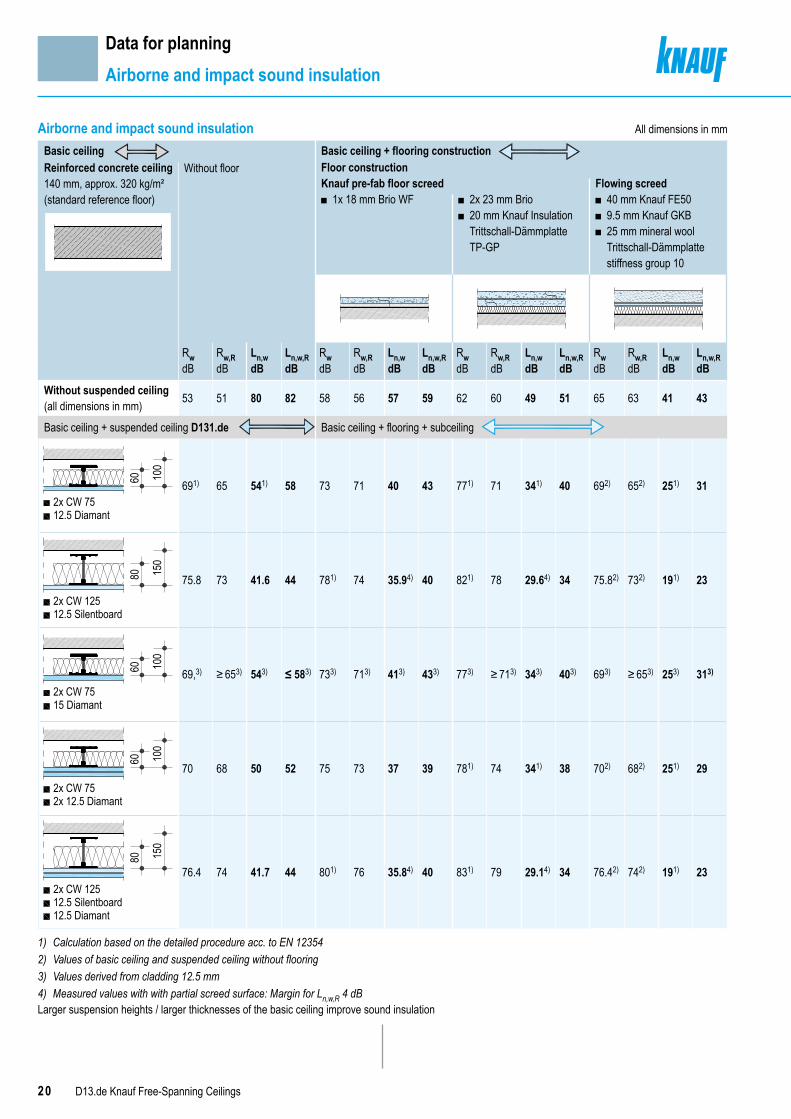
Airborne and impact sound insulationBasic ceiling Basic ceiling + flooring constructionReinforced concrete ceiling140 mm, approx. 320 kg/m²(standard reference floor)
Without floor Floor constructionKnauf pre-fab floor screed Flowing screed
■ 1x 18 mm Brio WF ■ 2x 23 mm Brio ■ 20 mm Knauf Insulation Trittschall-Dämmplatte TP-GP
■ 40 mm Knauf FE50 ■ 9.5 mm Knauf GKB ■ 25 mm mineral wool Trittschall-Dämmplatte stiffness group 10
RwdB
Rw,RdB
Ln,wdB
Ln,w,RdB
RwdB
Rw,RdB
Ln,wdB
Ln,w,RdB
RwdB
Rw,RdB
Ln,wdB
Ln,w,RdB
RwdB
Rw,RdB
Ln,wdB
Ln,w,RdB
Without suspended ceiling(all dimensions in mm) 53 51 80 82 58 56 57 59 62 60 49 51 65 63 41 43
Basic ceiling + suspended ceiling D131.de Basic ceiling + flooring + subceiling
100
60
12.5 Diamant2x CW 75
691) 65 541) 58 73 71 40 43 771) 71 341) 40 692) 652) 251) 31
150
80
2x CW 12512.5 Silentboard
75.8 73 41.6 44 781) 74 35.94) 40 821) 78 29.64) 34 75.82) 732) 191) 23
100
60
2x CW 7515 Diamant
69,3) ≥ 653) 543) ≤ 583) 733) 713) 413) 433) 773) ≥ 713) 343) 403) 693) ≥ 653) 253) 313)
100
60
2x CW 752x 12.5 Diamant
70 68 50 52 75 73 37 39 781) 74 341) 38 702) 682) 251) 29
12.5 Silentboard
150
80
12.5 Diamant
2x CW 12576.4 74 41.7 44 801) 76 35.84) 40 831) 79 29.14) 34 76.42) 742) 191) 23
1) Calculation based on the detailed procedure acc. to EN 123542) Values of basic ceiling and suspended ceiling without flooring3) Values derived from cladding 12.5 mm4) Measured values with with partial screed surface: Margin for Ln,w,R 4 dBLarger suspension heights / larger thicknesses of the basic ceiling improve sound insulation
All dimensions in mm

21D13.de Knauf Free-Spanning Ceilings
Data for planningAirborne and impact sound insulation
Ln,wwR alt.
Flooring
Basic ceiling
Free-spanning ceiling
Test configuration
Terms ■ Rw = weighted sound reduction index in dB without sound transmission via flanking building components
■ Ln,w = Weighted normalized impact sound level in dB without sound trans-mission via flanking building components
■ Index R is used to differentiate between the calculation value and the test stand values.
NoteThe verification of the new DIN 4109:2016-07 is no longer according to calculation values, but rather with the values obtained on the test rig, rounded off to a single position following the decimal point. Only at the end of the forecast after consideration of all the perimeter surfaces (flanking surfaces) involved in the transmission of sound is an element of forecast uncertainty included in dependence on the type of separating constructional component. For a transition period the Knauf System Data Sheets will specify both the test stand values as well as the calculated values used up to now.
Free-spanning ceiling D131.de ▪ Furring channel 2x CW 75 ▪ Insulation layer 60 mm
(e.g. Knauf Insulation Trennwand-Dämmplatte TP 115) ▪ Cladding
Demands on the insulation layer (e.g. from Knauf Insulation):Mineral wool insulation layer 60/80 mm acc. to EN 13162;length-related flow resistance acc. to EN 29053: r ≥ 5 kPa∙s/m²

22 D13.de Knauf Free-Spanning Ceilings
Data for planningPermissible furring channel spacings
All dimensions in mmPermissible furring channel spacingsBoard formats Maximum spacings furring channel
Without fire resistance
With fire resistance
Ball impact safety D131.de CW/UA single profile / CW/UA double profile
12.5 Silentboard 400
Axial spacing of furring channelacc. to pages 10, 12, 14, 16, 18
–12.5 Silentboard + 12.5 Diamant 400 400
12.5 500 –2x 12.5 500 50015 500 –18 – –20 / 2x 20 625 500
b

23D13.de Knauf Free-Spanning Ceilings
Data for planningAnchoring of loads
Attachment of loads to Knauf free-spanning suspended ceilingsAdditional loads, e.g. lighting fixtures, curtain rails and similar can be fixed to Knauf Free-Spanning Ceilings using universal dowel plugs, cavity dowels or spring toggle dowels or Knauf Hartmut Hohlraumdübel cavity dowels.Additional loads must be considered for determination of the maximum room width. If the entire weight consisting of insulation material and additional load more than 3 kg/m² and max. 15 kg/m², the room widths for the Multi-Level Ceiling System (pages 55, 56, 57) are to be used.
NotesHeavy loads must be anchored directly on load-bearing building elements (basic ceiling) or on auxiliary constructions.As an alternative separate rating of the maximum room widths is possible on request.
With application of the room widths including 3 kg/m² extra load (pages 9, 11, 13, 15, 17, 19)
With application of the room widths including 15 kg/m² extra load (pages 55, 56, 57)
Per load introduction surface of the Knauf Free-Spanning Ceiling the weight of the fastened components may not exceed the following thresholds:
Permissible weight per ceiling surface in kg/m² Permissible weight per ceiling surface in kg/m²Without fire resistance With fire resistance Without fire resistance With fire resistance1)
3 3 15 61) When implemented as a fire resistance ceiling with exposed ceiling
(Multi-Level Ceiling System, see page 54) 15 kg/m² is the permissible total weight for suspension of the exposed ceiling on the fire resistance ceiling (including insulation layer and attached loads).
Furthermore, the following conditions apply:For every anchoring point the following weights of components attached to the Free-Spanning Ceilings may not be exceeded:
Anchoring method Permissible weight per anchoring point in kg
Anchoring method Permissible weight per anchoring point in kg
Without fire resistance
With fire resistance
Without fire resistance
With fire resistance
Fastening in the cladding 3 0.5 Fastening in the cladding 6 0.5Fastening to the grid 3 3 Fastening to the grid 10 10
The minimum spacings between the individual attached loads can be taken from the following diagram:
7570656055504540353025201510
0 2 3 4 5 6 7 8 9 10
Radiu
s in c
m
Single load in kg1
50
Fastening to the cladding possible(without fire resistance)
Example of an attachment scheme with 15 kg/m²
10 kg
3 kgr = 25 cm
r = 46 cm
6 kgr = 35.5 cm
1 kg
r = 15 cm
0.5 kg
r = 10.5 cm
3 kg/m² additional load (application of the room widths up to 3 kg/m²) 6 kg/m² additional load (application of the room widths up to 15 kg/m²
with fire resistance) 15 kg/m² additional load (application of the room widths up to 15 kg/m²
with Multi-Level Ceiling System / without fire resistance)
Fastening in the cladding Fastening to the grid NoteKnauf Hartmut Hohl-raumdübel cavity dowelScrew M5
Knauf multi-purpose screw FNe.g. curtain rail
The attached loads can be introduced with several anchoring elements.
24 D13.de Knauf Free-Spanning Ceilings
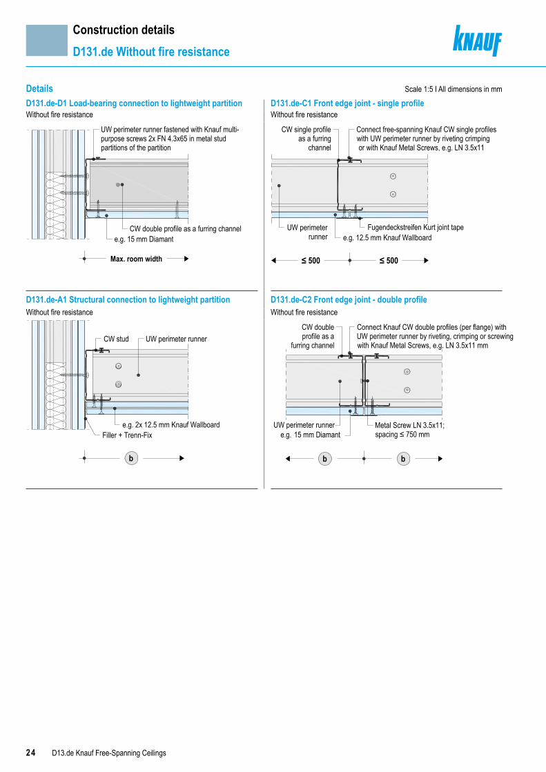
DetailsD131.de-D1 Load-bearing connection to lightweight partition D131.de-C1 Front edge joint - single profileWithout fire resistance Without fire resistance
D131.de-A1 Structural connection to lightweight partition D131.de-C2 Front edge joint - double profileWithout fire resistance Without fire resistance
Max. room width
UW perimeter runner fastened with Knauf multi-purpose screws 2x FN 4.3x65 in metal stud partitions of the partition
e.g. 15 mm DiamantCW double profile as a furring channel
e.g. 12.5 mm Knauf WallboardFugendeckstreifen Kurt joint tape
≤ 500 ≤ 500
Connect free-spanning Knauf CW single profileswith UW perimeter runner by riveting crimping or with Knauf Metal Screws, e.g. LN 3.5x11
CW single profileas a furring
channel
UW perimeterrunner
UW perimeter runnerCW stud
Filler + Trenn-Fixe.g. 2x 12.5 mm Knauf Wallboard
b
Metal Screw LN 3.5x11;spacing ≤ 750 mm
b
Connect Knauf CW double profiles (per flange) withUW perimeter runner by riveting, crimping or screwingwith Knauf Metal Screws, e.g. LN 3.5x11 mm
CW doubleprofile as a
furring channel
e.g. 15 mm Diamant
b
UW perimeter runner
Construction detailsD131.de Without fire resistance
Scale 1:5 I All dimensions in mm

25D13.de Knauf Free-Spanning Ceilings
Details Scale 1:5
D131.de-D100 Load-bearing connection to solid wall D131.de-B100 Long edge jointWithout fire resistance Without fire resistance
D131.de-D101 Load-bearing connection to lightweight partition with Knauf Hartmut Hohlraumdübel cavity dowel
D131.de-D102 Load-bearing connection to lightweight partition with Universalschraube FN multi-purpose screw
Without fire resistance Without fire resistance
UW perimeter runnerConnection bolt M8
Filler + Trenn-FixDrywall Screw TB
UA double profile as a furring channel
Max. room width
e.g. Knauf Cubo Connection BracketFixing screw M8, a ≤ 750 mm
Drywall Screw TB
UA double profile as a furring channel
e.g. 12.5 mm Knauf Wallboard
Max. room width
UW perimeter runner
Knauf Hartmut Hohlraumdübel cavity dowelfastened in the wall cladding
e.g. 12.5 mm Diamant
Connection bolt M8e.g. Knauf Connection Angle
Connection bolt M8
Drywall Screw TBUA double profile as a furring channel
Max. room width
Knauf multi-purpose screws FN connected tometal stud partitions of the wall or metal traverses
e.g. Knauf Cubo Connection Bracket
Construction detailsD131.de Without fire resistance
Note When using Knauf Anschlusswinkel Connection Angle with Universalschraube FN multi-purpose screw or Knauf Hartmut Hohlraumdübel cavity dowels, screw attachment is without a washer in the smallest holes of the Anschlusswinwel connection angle.
26 D13.de Knauf Free-Spanning Ceilings
Details Scale 1:5
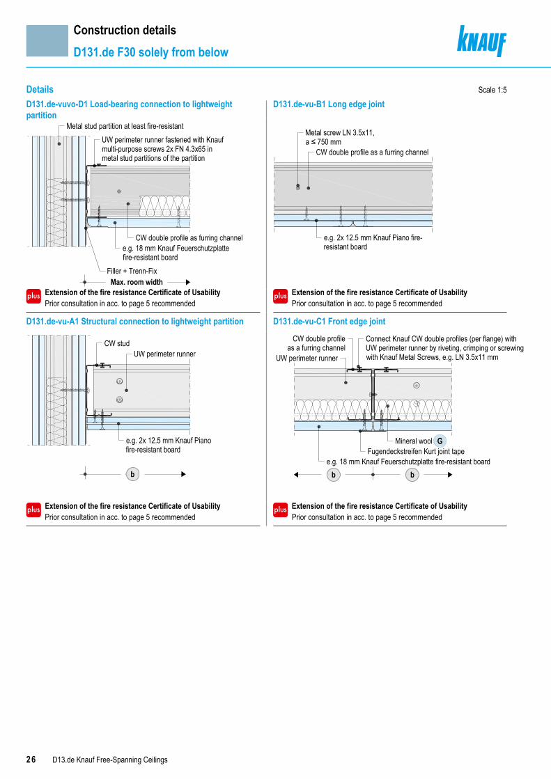
D131.de-vuvo-D1 Load-bearing connection to lightweight partition
D131.de-vu-B1 Long edge joint
Extension of the fire resistance Certificate of Usability Prior consultation in acc. to page 5 recommended
Extension of the fire resistance Certificate of Usability Prior consultation in acc. to page 5 recommended
D131.de-vu-A1 Structural connection to lightweight partition D131.de-vu-C1 Front edge joint
Extension of the fire resistance Certificate of Usability Prior consultation in acc. to page 5 recommended
Extension of the fire resistance Certificate of Usability Prior consultation in acc. to page 5 recommended
Max. room width
UW perimeter runner fastened with Knaufmulti-purpose screws 2x FN 4.3x65 inmetal stud partitions of the partition
e.g. 18 mm Knauf Feuerschutzplattefire-resistant board
Filler + Trenn-Fix
CW double profile as furring channel
Metal stud partition at least fire-resistant
CW double profile as a furring channel
Metal screw LN 3.5x11,a ≤ 750 mm
e.g. 2x 12.5 mm Knauf Piano fire-resistant board
b
CW stud
e.g. 2x 12.5 mm Knauf Piano fire-resistant board
UW perimeter runner
Fugendeckstreifen Kurt joint tapee.g. 18 mm Knauf Feuerschutzplatte fire-resistant board
Mineral wool G
Connect Knauf CW double profiles (per flange) withUW perimeter runner by riveting, crimping or screwingwith Knauf Metal Screws, e.g. LN 3.5x11 mm
CW double profileas a furring channel
UW perimeter runner
bb
Construction detailsD131.de F30 solely from below
27D13.de Knauf Free-Spanning Ceilings
Details Scale 1:5
Construction detailsD131.de F30 solely from below
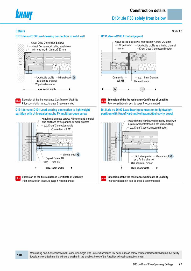
D131.de-vu-D100 Load-bearing connection to solid wall D131.de-vu-C100 Front edge joint
Extension of the fire resistance Certificate of Usability Prior consultation in acc. to page 5 recommended
Extension of the fire resistance Certificate of Usability Prior consultation in acc. to page 5 recommended
D131.de-vuvo-D101 Load-bearing connection to lightweight partition with Universalschraube FN multi-purpose screw
D131.de-vu-D102 Load-bearing connection to lightweight partition with Knauf Hartmut Hohlraumdübel cavity dowel
Extension of the fire resistance Certificate of Usability Prior consultation in acc. to page 5 recommended
Extension of the fire resistance Certificate of Usability Prior consultation in acc. to page 5 recommended
G
Max. room width
Mineral woolUA double profileas a furring channel
UW perimeter runner
Knauf Cubo Connection BracketKnauf Deckennagel ceiling steel dowelwith washer, d = 2 mm, Ø 30 mm Knauf Cubo Connection Bracket
e.g. 18 mm DiamantDiamant screw
Connectionbolt M8
bb
Knauf ceiling steel dowel with washer = 2mm, Ø 30 mmUW perimeterrunner
UA double profile as a furring channel
GDrywall Screw TB
Connection bolt M8
Filler + Trenn-Fix
Mineral wool
Max. room width
Knauf multi-purpose screws FN connected to metalstud partitions or the partition or metal traverse
e.g. Knauf Connection Angle
GMineral woolUA double profileas a furring channel
UW perimeter runner
Max. room width
Knauf Hartmut Hohlraumdübel cavity dowel withsuitable washer fastened in the wall cladding
e.g. Knauf Cubo Connection Bracket
Note When using Knauf Anschlusswinkel Connection Angle with Universalschraube FN multi-purpose screw or Knauf Hartmut Hohlraumdübel cavity dowels, screw attachment is without a washer in the smallest holes of the Anschlusswinwel connection angle.

28 D13.de Knauf Free-Spanning Ceilings
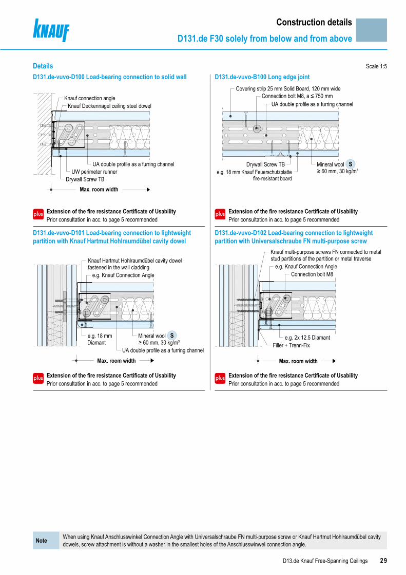
Details
Construction detailsD131.de F30 solely from below and from above
Scale 1:5 I All dimensions in mmD131.de-vuvo-D1 Load-bearing connection to lightweight partition
D131.de-vuvo-B1 Long edge joint
Extension of the fire resistance Certificate of Usability Prior consultation in acc. to page 5 recommended
D131.de-vuvo-A1 Structural connection to lightweight partition D131.de-vuvo-C1 Front edge joint
Extension of the fire resistance Certificate of Usability Prior consultation in acc. to page 5 recommended
Max. room width
UW perimeter runner fastened with Knaufmulti-purpose screws 2x FN 4.3x65 inmetal stud partitions of the wall
Metal stud partition at least fire resistant
CW double stud profileas a furring channel
Covering strips 25 mmMassivbauplatte solid board, 120 mm wide
CW double profileas a furring channel
e.g. 18 mm Knauf Feuerschutzplattefire-resistant board
CW stud
Covering strip 25 mm Solid Board,60 mm wide
≤ 625b
100120
1010
Fugendeckstreifen Kurt joint tapeMineral wool≥ 60 mm, 30 kg/m³
S
Covering strips25 mm Solid Board,120 mm wide
UW perimeterrunner
≤ 625b≤ 625b
e.g. 18 mm Knauf Feuerschutzplattefire-resistant board
29D13.de Knauf Free-Spanning Ceilings
Details Scale 1:5
Construction detailsD131.de F30 solely from below and from above
Note When using Knauf Anschlusswinkel Connection Angle with Universalschraube FN multi-purpose screw or Knauf Hartmut Hohlraumdübel cavity dowels, screw attachment is without a washer in the smallest holes of the Anschlusswinwel connection angle.
D131.de-vuvo-D100 Load-bearing connection to solid wall D131.de-vuvo-B100 Long edge joint
Extension of the fire resistance Certificate of Usability Prior consultation in acc. to page 5 recommended
Extension of the fire resistance Certificate of Usability Prior consultation in acc. to page 5 recommended
D131.de-vuvo-D101 Load-bearing connection to lightweight partition with Knauf Hartmut Hohlraumdübel cavity dowel
D131.de-vuvo-D102 Load-bearing connection to lightweight partition with Universalschraube FN multi-purpose screw
Extension of the fire resistance Certificate of Usability Prior consultation in acc. to page 5 recommended
Extension of the fire resistance Certificate of Usability Prior consultation in acc. to page 5 recommended
Max. room width
UA double profile as a furring channelUW perimeter runner
Drywall Screw TB
Knauf connection angleKnauf Deckennagel ceiling steel dowel
S
Connection bolt M8, a ≤ 750 mmCovering strip 25 mm Solid Board, 120 mm wide
Mineral wool≥ 60 mm, 30 kg/m³
UA double profile as a furring channel
Drywall Screw TBe.g. 18 mm Knauf Feuerschutzplatte
fire-resistant board
Se.g. 18 mmDiamant
Mineral wool≥ 60 mm, 30 kg/m³
UA double profile as a furring channel
Max. room width
e.g. Knauf Connection Angle
Knauf Hartmut Hohlraumdübel cavity dowelfastened in the wall cladding
Filler + Trenn-Fix
Connection bolt M8
e.g. 2x 12.5 Diamant
Max. room width
Knauf multi-purpose screws FN connected to metalstud partitions of the partition or metal traverse
e.g. Knauf Connection Angle

30 D13.de Knauf Free-Spanning Ceilings
Details
Construction detailsD131.de F60 solely from below and from above
Scale 1:5 I All dimensions in mmD131.de-vuvo-D3 Load-bearing connection to lightweight partition
D131.de-vuvo-B3 Long edge joint
Extension of the fire resistance Certificate of Usability Prior consultation in acc. to page 5 recommended
D131.de-vuvo-A3 Structural connection to lightweight partition D131.de-vuvo-C3 Front edge joint
Extension of the fire resistance Certificate of Usability Prior consultation in acc. to page 5 recommended
Max. room width
UW perimeter runner fastened withKnauf multi-purpose screws 2x FN4.3x65 in metal stud partitions of the wall
CW double stud profileas a furring channel
Filler+ Trenn-Fix
≥ 50
e.g. 2x 12.5 mm Knauf Piano fire-resistant board
Covering strips 12.5 mm Knauf Piano fire-resistant board, 100 mm wide
Full surface covering looselyapplied and overlapping
≤ 500b
Covering strip 12.5 mm Knauf Piano fire-resistant board, 50 mm wide
CW stud e.g. 2x 12.5 mm Knauf Piano fire-resistant board
SMineral wool≥ 50 mm, 50 kg/m³
≥ 100
CW double profile asa furring channel
e.g. 2x 12.5 mm Knauf Piano fire-resistant board
Full surface loose coveringapplied loosely and tightly jointed
≤ 500b ≤ 500b

31D13.de Knauf Free-Spanning Ceilings
Details
Construction detailsD131.de F60 solely from below and from above
Scale 1:5 I All dimensions in mmD131.de-vuvo-D200 Load-bearing connection to solid wall D131.de-vuvo-C200 Front edge joint
Extension of the fire resistance Certificate of Usability Prior consultation in acc. to page 5 recommended
Extension of the fire resistance Certificate of Usability Prior consultation in acc. to page 5 recommended
D131.de-vuvo-D201 Load-bearing connection to lightweight partition with Knauf Hartmut Hohlraumdübel cavity dowel
D131.de-vuvo-D203 Load-bearing connection to lightweight partition with Universalschraube FN multi-purpose screw
Extension of the fire resistance Certificate of Usability Prior consultation in acc. to page 5 recommended
Extension of the fire resistance Certificate of Usability Prior consultation in acc. to page 5 recommended
Connection bolt M8Covering strips 12.5 mm Knauf Piano fire-resistant board, 120 mm wide
UA double profile as a furring channel
Max. room width
UW perimeter runnerS
Diamant screwMineral wool≥ 50 mm, 50 kg/m³
≤ 500
e.g. 2x 12.5 mm Diamant
≤ 500
Knauf CuboConnection Bracket
b
Full surface covering loosely applied and tightly jointed
b
UW perimeter runnerUA double profile
Max. room width
UW perimeter runnerKnauf multi-purpose screw FN
Connection bolt M8
Knauf Hartmut Hohlraumdübel cavity dowelfastened in the wall cladding
e.g. Knauf Connection Angle
UA double profile as a furring channelUW perimeter runner
Max. room width
Knauf multi-purpose screws FN connected to metalstud partitions of the wall or metal traverse
e.g. Knauf Cubo Connection Bracket
Note When using Knauf Anschlusswinkel Connection Angle with Universalschraube FN multi-purpose screw or Knauf Hartmut Hohlraumdübel cavity dowels, screw attachment is without a washer in the smallest holes of the Anschlusswinwel Connection Angle.
32 D13.de Knauf Free-Spanning Ceilings
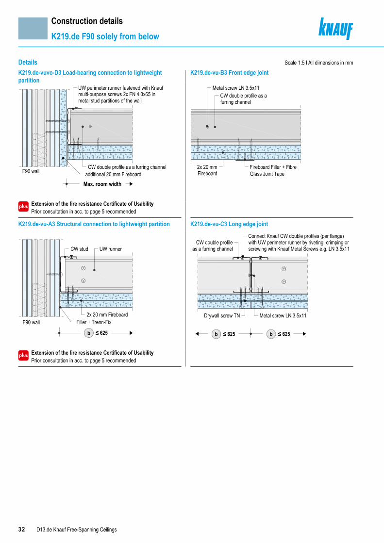
Details
Construction detailsK219.de F90 solely from below
Scale 1:5 I All dimensions in mmK219.de-vuvo-D3 Load-bearing connection to lightweight partition
K219.de-vu-B3 Front edge joint
Extension of the fire resistance Certificate of Usability Prior consultation in acc. to page 5 recommended
K219.de-vu-A3 Structural connection to lightweight partition K219.de-vu-C3 Long edge joint
Extension of the fire resistance Certificate of Usability Prior consultation in acc. to page 5 recommended
UW perimeter runner fastened with Knaufmulti-purpose screws 2x FN 4.3x65 inmetal stud partitions of the wall
additional 20 mm FireboardF90 wallCW double profile as a furring channel
Max. room width
CW double profile as afurring channel
Metal screw LN 3.5x11
Fireboard Filler + FibreGlass Joint Tape
2x 20 mmFireboard
UW runnerCW stud
2x 20 mm FireboardF90 wall Filler + Trenn-Fix
≤ 625b
Metal screw LN 3.5x11
CW double profileas a furring channel
Connect Knauf CW double profiles (per flange)with UW perimeter runner by riveting, crimping orscrewing with Knauf Metal Screws e.g. LN 3.5x11
Drywall screw TN
≤ 625b≤ 625b
33D13.de Knauf Free-Spanning Ceilings
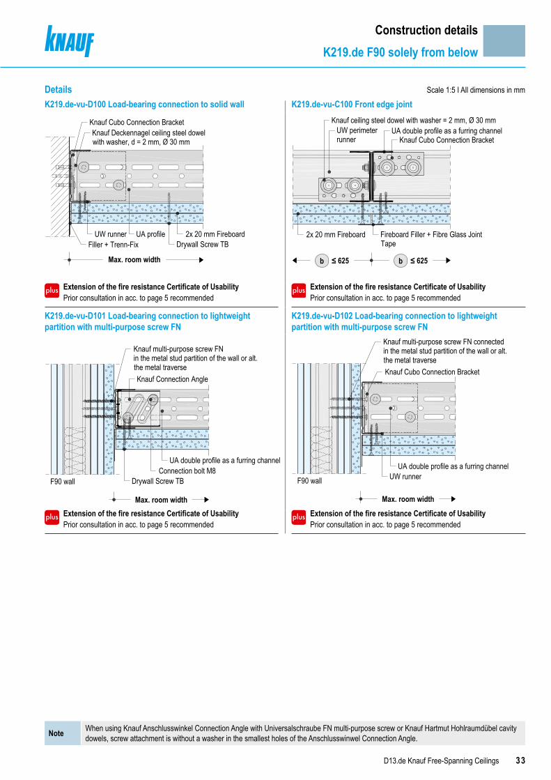
Details
Construction detailsK219.de F90 solely from below
Scale 1:5 I All dimensions in mm
K219.de-vu-D100 Load-bearing connection to solid wall K219.de-vu-C100 Front edge joint
Extension of the fire resistance Certificate of Usability Prior consultation in acc. to page 5 recommended
Extension of the fire resistance Certificate of Usability Prior consultation in acc. to page 5 recommended
K219.de-vu-D101 Load-bearing connection to lightweight partition with multi-purpose screw FN
K219.de-vu-D102 Load-bearing connection to lightweight partition with multi-purpose screw FN
Extension of the fire resistance Certificate of Usability Prior consultation in acc. to page 5 recommended
Extension of the fire resistance Certificate of Usability Prior consultation in acc. to page 5 recommended
Max. room width
2x 20 mm FireboardDrywall Screw TB
UW runnerFiller + Trenn-Fix
UA profile
Knauf Cubo Connection BracketKnauf Deckennagel ceiling steel dowelwith washer, d = 2 mm, Ø 30 mm
2x 20 mm Fireboard
≤ 625b≤ 625b
Fireboard Filler + Fibre Glass JointTape
Knauf Cubo Connection Bracket
Knauf ceiling steel dowel with washer = 2 mm, Ø 30 mmUW perimeterrunner
UA double profile as a furring channel
Drywall Screw TBConnection bolt M8
UA double profile as a furring channel
Max. room width
Knauf multi-purpose screw FNin the metal stud partition of the wall or alt. the metal traverseKnauf Connection Angle
F90 wall
Max. room width
UW runnerUA double profile as a furring channel
Knauf multi-purpose screw FN connected in the metal stud partition of the wall or alt. the metal traverseKnauf Cubo Connection Bracket
F90 wall
Note When using Knauf Anschlusswinkel Connection Angle with Universalschraube FN multi-purpose screw or Knauf Hartmut Hohlraumdübel cavity dowels, screw attachment is without a washer in the smallest holes of the Anschlusswinwel Connection Angle.

34 D13.de Knauf Free-Spanning Ceilings
Details
Construction detailsK219.de F90 solely from below and from above
Scale 1:5 I All dimensions in mmK219.de-vuvo-D3 Load-bearing connection to lightweight partition
K219.de-vuvo-B3 Front edge joint
K219.de-vuvo-A3 Structural connection to lightweight partition K219.de-vuvo-C3 Long edge joint
Extension of the fire resistance Certificate of Usability Prior consultation in acc. to page 5 recommended
Max. room width
100 mm Flex Profile
UW perimeter runner fixed in the partition metal studs or Flex Profile with Knauf multi-purpose screws 2x FN 4.3x65
Additional 20 mm Fireboard
CW double profile as a furring channelF90 wall
Metal screw LN 3.5x11
Covering strip Fireboard12.5 mm, 120 mm wide
Covering strip Fireboard 12.5 mm,120 mm wide
Mineral wool ≥ 60 mm, 50 kg/m³SFull surface covering looselyapplied and tightly jointed
Fireboard-Spachtel filler+ Fibre glass joint tape
Drywall screw TN20 mm Fireboard
Covering strip Fireboard 12.5 mm,60 mm wide
UW runner
CW stud
Filler + Trenn-Fix20 mm Fireboard
≤ 625b
F90 wall
≥ 100≥ 120
1010
Metal screw LN 3.5x11
Covering strip Fireboard12.5 mm, 120 mm wide
Mineral wool≥ 60 mm, 50 kg/m³ Schnellbauschraube TN Drywall screw
S
Full surface covering loosely applied and tightly jointed
≤ 625b≤ 625b
Note When applied with UA furring channels it is possible to omit the covering strips on the upper and lower flanges of the double profiles.
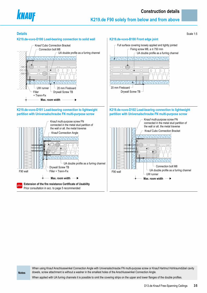
35D13.de Knauf Free-Spanning Ceilings
Details Scale 1:5
Construction detailsK219.de F90 solely from below and from above
K219.de-vuvo-D100 Load-bearing connection to solid wall K219.de-vuvo-B100 Front edge joint
K219.de-vuvo-D101 Load-bearing connection to lightweight partition with Universalschraube FN multi-purpose screw
K219.de-vuvo-D102 Load-bearing connection to lightweight partition with Universalschraube FN multi-purpose screw
Extension of the fire resistance Certificate of Usability Prior consultation in acc. to page 5 recommended
UA double profile as a furring channel
20 mm Fireboard
Max. room width
Filler+ Trenn-Fix
UW runnerDrywall Screw TB
Knauf Cubo Connection BracketConnection bolt M8 Fixing screw M8, a ≤ 750 mm
Full surface covering loosely applied and tightly jointed
20 mm Fireboard
UA double profile as a furring channel
Drywall Screw TB
Drywall Screw TBFiller + Trenn-Fix
UA double profile as a furring channel
Max. room width
Knauf multi-purpose screw FN connected in the metal stud partition of the wall or alt. the metal traverse
F90 wall
Knauf Connection Angle
Max. room widthUW runner
UA double profile as a furring channelConnection bolt M8
F90 wall
Knauf multi-purpose screw FN connected in the metal stud partition of the wall or alt. the metal traverseKnauf Cubo Connection Bracket
NotesWhen using Knauf Anschlusswinkel Connection Angle with Universalschraube FN multi-purpose screw or Knauf Hartmut Hohlraumdübel cavity dowels, screw attachment is without a washer in the smallest holes of the Anschlusswinkel Connection Angle.When applied with UA furring channels it is possible to omit the covering strips on the upper and lower flanges of the double profiles.

36 D13.de Knauf Free-Spanning Ceilings
Details Scale 1:5 I All dimensions in mmD131.de-SO-D1 Connection to solid wall with shadow gap D131.de-SO-A1 Connection to solid wall with shadow gap
Extension of the fire resistance Certificate of Usability Prior consultation in acc. to page 5 recommended
D131.de-SO-C3 Movement joint D131.de-SO-A2 Ceiling bulkhead
Extension of the fire resistance Certificate of Usability Prior consultation in acc. to page 5 recommended
Extension of the fire resistance Certificate of Usability Prior consultation in acc. to page 5 recommended
≤ 20 ≥ 5
Knauf Fugenfüller Leicht filler
Board strips 25 mm Solid BoardNon-combustible fasteners suitablefor the substrate,a ≤ 300 mm
≤ 20 ≥ 5
Board strips 25 mm Solid BoardSchnellbauschraube TN 3.5x35 Drywall Screw
CW studEdge Trim if required
UW perimeter runner
a ≤ 20 mm
≥ 25 a ≥ 25 a
≤ 100 ≤ 100
Glue on one side withKnauf Fugenfüller
Leicht
Board strips18 mm Knauf fire-resistant board
Covering strips25 mm SolidBoard
Edge trimif necessary
a ≤ 20 mm
18 mm Knauf fire-resistant board
≥ 70
Covering strip 25 mmSolid Board
CW stud
18 mm Knauf fire-resistant board
Knauf multi-purpose screw FN, fastento metal stud ceiling bulkhead
Ceiling bulkhead at very least fire resistant
Construction detailsSpecial details
37D13.de Knauf Free-Spanning Ceilings
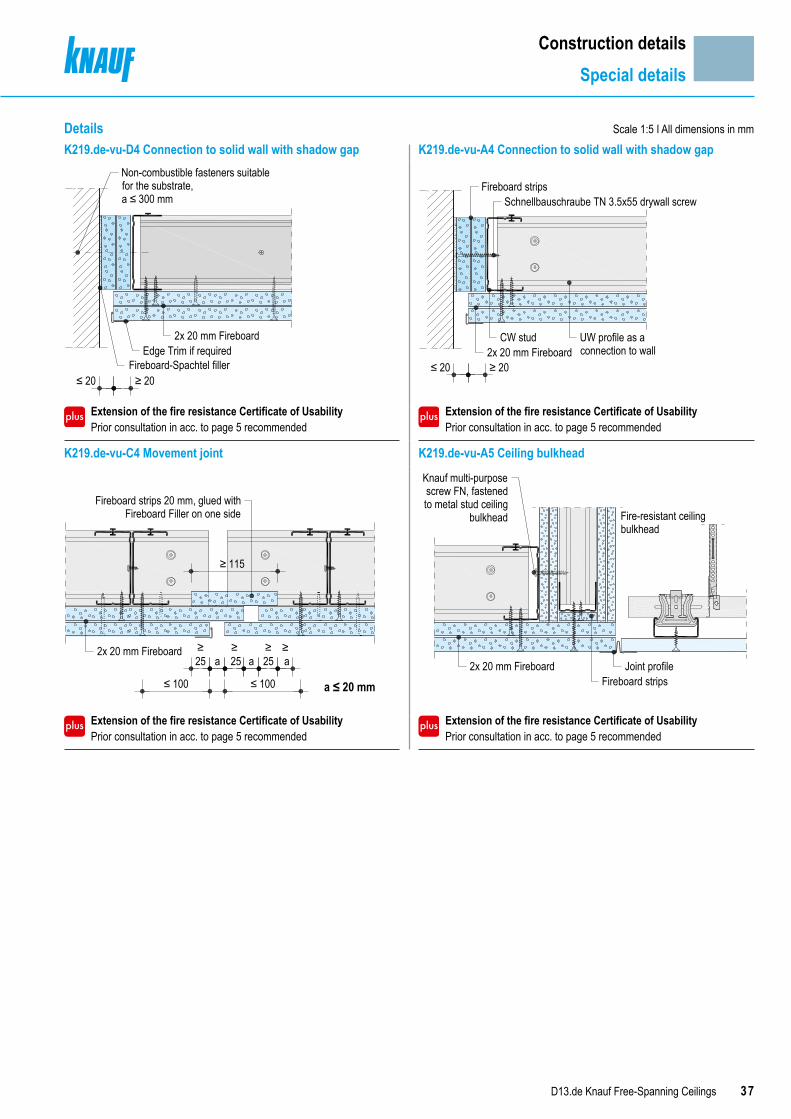
Details Scale 1:5 I All dimensions in mmK219.de-vu-D4 Connection to solid wall with shadow gap K219.de-vu-A4 Connection to solid wall with shadow gap
Extension of the fire resistance Certificate of Usability Prior consultation in acc. to page 5 recommended
Extension of the fire resistance Certificate of Usability Prior consultation in acc. to page 5 recommended
K219.de-vu-C4 Movement joint K219.de-vu-A5 Ceiling bulkhead
Extension of the fire resistance Certificate of Usability Prior consultation in acc. to page 5 recommended
Extension of the fire resistance Certificate of Usability Prior consultation in acc. to page 5 recommended
2x 20 mm Fireboard
Fireboard-Spachtel fillerEdge Trim if required
≤ 20 ≥ 20
Non-combustible fasteners suitablefor the substrate,a ≤ 300 mm
≤ 20 ≥ 20
Fireboard stripsSchnellbauschraube TN 3.5x55 drywall screw
UW profile as aconnection to wall
CW stud2x 20 mm Fireboard
≥25 a
≥ 25 a
≥25
≥ a
≤ 100 ≤ 100
Fireboard strips 20 mm, glued withFireboard Filler on one side
2x 20 mm Fireboard
≥ 115
a ≤ 20 mm2x 20 mm Fireboard
Fireboard stripsJoint profile
Fire-resistant ceilingbulkhead
Knauf multi-purposescrew FN, fastenedto metal stud ceiling
bulkhead
Construction detailsSpecial details

38 D13.de Knauf Free-Spanning Ceilings
Details
Construction detailsSpecial details
Scale 1:5 I All dimensions in mmK219.de-vuvo-D4 Connection to wall with shadow gap K219.de-vuvo-A4 Connection to wall with shadow gap
Extension of the fire resistance Certificate of Usability Prior consultation in acc. to page 5 recommended
K219.de-vuvo-C4 Movement joint K219.de-vuvo-A5 Ceiling bulkhead
Extension of the fire resistance Certificate of Usability Prior consultation in acc. to page 5 recommended
Extension of the fire resistance Certificate of Usability Prior consultation in acc. to page 5 recommended
≤ 20 ≥ 5
Non-combustible fasteners suitablefor the substrate,a ≤ 300 mm
20 mm Fireboard
Schnellbauschraube TN 3.5x45drywall screw
≤ 20 ≥ 5
20 mm Fireboard
Fireboard stripsSchnellbauschraube TN drywall screw
Corner Trim if requiredFireboard-Spachtel filler
≥ 25 a ≥ 25 ≥ a
approx. 100 approx. 100
Fireboard strips 20 mm, glued withFireboard Filler on one side
20 mm Fireboard
≥ 70
a ≤ 20 mm
Fire-resistant ceilingbulkhead
Knauf multi-purpose screwFN, fastened to metal stud inceiling bulkhead
e.g. joint profile≥ 10Fireboard strips
20 mm Fireboard

39D13.de Knauf Free-Spanning Ceilings
Scheme drawings I All dimensions in mm
Scale 1:5 I All dimensions in mm
Construction detailsSpecial details
Fire protection encasement for built-in lightingFire resistance F30 solely from below and from above
B
B
≤ 400≤ 625
C C
Steel staples
Additional Knauf CW profile
Knauf CW double stud profile
Cladding, ≤ 400 x 1000 mmmade of 25 mm Solid Board
Front side stapling of the cladding
Cladding Staple lengths Maximum spacingsmm mm mm20 50
10025 64
Stapling of the front side cladding with steel staples acc. to DIN 18182-2 or EN 14566 (e.g. Haubold or Poppers-Senco).
DetailsD131.de-SO-C11 Lateral section of built-in lighting D131.de-SO-B11 Longitudinal section of built-in lightingFire resistance F30 solely from below and from above Fire resistance F30 solely from below and from above
Extension of the fire resistance Certificate of Usability Prior consultation in acc. to page 5 recommended
Extension of the fire resistance Certificate of Usability Prior consultation in acc. to page 5 recommended
D131.de-SO-C5 Lateral section of built-in lighting D131.de-SO-B5 Longitudinal section of built-in lightingFire resistance F30 solely from below and from above Fire resistance F30 solely from below and from above
Extension of the fire resistance Certificate of Usability Prior consultation in acc. to page 5 recommended
Extension of the fire resistance Certificate of Usability Prior consultation in acc. to page 5 recommended
Spacing of furring channels ≤ 625
25 mm Solid Board l = Length of illumination box+ 2x ≥ 200 mm, w ≥ 625 mm, applied loosely
Lighting fixture max.8 kg, attachaccording tomanufacturersinstructions
≤ 505
Mineral wool ≥ 60 mm, 30 kg/m³
≥ 25
≥ 25
≥ 60≥ 60
S
Optional height adjustment with GKF board strips,≥ 60 mm wide, adhesively bonded or stapled to cladding
S
≥ 200
≥ 25
Lighting fixturemax. 8 kg, attachaccording tomanufacturersinstructions
≥ 25
Mineral wool ≥ 60 mm, 30 kg/m³
25 mm Solid Board l = length of illumination box+ 2x ≥ 200 mm w ≥ 625 mm, applied loosely
Optional height adjustment with GKF board strips,≥ 60 mm wide, adhesively bonded or stapled to cover
≤ 400Spacing of furring channels ≤ 625
≥ 25
Lighting fixture max.10 kg, attachaccording tomanufacturersinstructions
Additional profile (for openings up to200 x 200 mm not required)
Cladding≤ 400 x 1000 mm made
of 25 mm Solid Board
Steel staplesacc. to DIN 18182 ≥
25
S
≤ 1000
Lighting fixturemax. 10 kg, attachaccording tomanufacturersinstructions
Steel staplesacc. to DIN 18182Cladding
≤ 400 x 1000 mm made of25 mm Solid Board
Mineral wool≥ 60 mm, 30 kg/m³
≥ 25
≥ 25
40 D13.de Knauf Free-Spanning Ceilings
Scheme drawings I All dimensions in mm
Construction detailsSpecial details
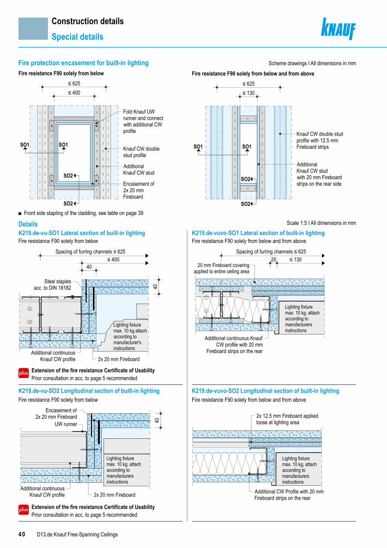
Scale 1:5 I All dimensions in mmK219.de-vu-SO1 Lateral section of built-in lighting K219.de-vuvo-SO1 Lateral section of built-in lightingFire resistance F90 solely from below Fire resistance F90 solely from below and from above
Extension of the fire resistance Certificate of Usability Prior consultation in acc. to page 5 recommended
K219.de-vu-SO2 Longitudinal section of built-in lighting K219.de-vuvo-SO2 Longitudinal section of built-in lightingFire resistance F90 solely from below Fire resistance F90 solely from below and from above
Extension of the fire resistance Certificate of Usability Prior consultation in acc. to page 5 recommended
≤ 400Spacing of furring channels ≤ 625
40
40
Additional continuousKnauf CW profile
Steel staplesacc. to DIN 18182
2x 20 mm Fireboard
Lighting fixturemax. 10 kg attachaccording tomanufacturer'sinstructions
20 ≤ 130Spacing of furring channels ≤ 625
Additional continuous KnaufCW profile with 20 mm
Fireboard strips on the rear
Lighting fixturemax. 10 kg, attachaccording tomanufacturersinstructions
20 mm Fireboard coveringapplied to entire ceiling area
40
Encasement of2x 20 mm Fireboard
Additional continuousKnauf CW profile
Lighting fixturemax. 10 kg, attachaccording tomanufacturersinstructions
UW runner
2x 20 mm Fireboard
2x 12.5 mm Fireboard appliedloose at lighting area
Lighting fixturemax. 10 kg, attachaccording tomanufacturersinstructions
Additional CW Profile with 20 mmFireboard strips on the rear
Fire protection encasement for built-in lightingFire resistance F90 solely from below
■
≤ 400≤ 625
SO2
SO2
SO1SO1Knauf CW doublestud profile
AdditionalKnauf CW stud
Encasement of2x 20 mmFireboard
Fold Knauf UWrunner and connectwith additional CWprofile
Front side stapling of the cladding, see table on page 39
Fire resistance F90 solely from below and from above
Knauf CW double studprofile with 12.5 mmFireboard strips
AdditionalKnauf CW studwith 20 mm Fireboardstrips on the rear side
≤ 130≤ 625
SO1
SO2
SO2
SO1
Details

41D13.de Knauf Free-Spanning Ceilings
Construction detailsSpecial details
Scheme drawingKnauf access panel SYSTEM D131 BS 30Top view
Axial spacing of furring channel 625 mm
Access element
CW double studprofile withcovering strips
Transverse section
Longitudinal section
Cross-section ■ Solely from below and from above ■ Solely from below
Access element
6 mm
81.5 mm
6 mm
81.5 mm
Size (450 mm)
Opening dimension of cladding(= size + 2x 6 mm)
(= clearance)Knauf board GKF
CW double profileas a furring channel
Covering strip GKF
Longitudinal section ■ Solely from below and from above ■ Solely from below
Opening dimension of cladding(= size + 2x 6 mm)
Extension of the fire resistance Certificate of Usability ■ Installation of access panel seals
Prior consultation in acc. to page 5 is recommended.
Notes
Cladding thickness, dimensions, available options and further information, see Product Data Sheet E131.de.Observe the enclosed installation instructions of the access panels.

42 D13.de Knauf Free-Spanning Ceilings
Construction detailsSpecial details
Knauf access panel SYSTEM K219 BS90 solely from belowTop view
Axial spacing of furring channel 625 mm
Transverse section
Access panel
Longitudinal section
Fold UW Profile andslide it onto thedouble profile
12.5 mm Fireboardstrips - all around(after installation ofthe access panel)
CW double studprofile withcovering strips
Cross-section
Clearance(≤ 375 mm)
Access panel
Opening dimension of cladding
≥ 50 mm
2x 20 mm Fireboard
Knauf board strips t ≥ 12.5 mmto secure positioning on the long sides
Push UW runner onto doubleprofile and connect it
Longitudinal section
2x 20 mm Fireboard Access panel
20 mm FireboardUW profile frame
Clearance(≤ 600 mm)
12.5 mm Fireboard strips allaround - before hatch installation
≥ 50 mm
Extension of the fire resistance Certificate of Usability ■ Installation of access panel seals
Prior consultation in acc. to page 5 is recommended.Notes
For further information see Product Data Sheet E219.deObserve the enclosed installation instructions of the access panels.
Scheme drawing
Additional grid
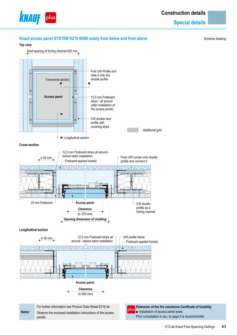
43D13.de Knauf Free-Spanning Ceilings
Construction detailsSpecial details
Knauf access panel SYSTEM K219 BS90 solely from below and from aboveTop view
Axial spacing of furring channel 625 mm
Transverse section
Access panel
Longitudinal section
Fold UW Profile andslide it onto thedouble profile
12.5 mm Fireboardstrips - all around(after installation ofthe access panel)
CW double studprofile withcovering strips
Cross-section
20 mm Fireboard
Clearance(≤ 375 mm)
Access panel CW doubleprofile as afurring channel
≥ 50 mm Push UW runner onto doubleprofile and connect itFireboard applied loosely
12.5 mm Fireboard strips all around -before hatch installation
Opening dimension of cladding
Longitudinal section
Clearance(≤ 600 mm)
≥ 50 mmFireboard applied loosely
12.5 mm Fireboard strips allaround - before hatch installation
UW profile frame
Access panel
Extension of the fire resistance Certificate of Usability ■ Installation of access panel seals
Prior consultation in acc. to page 5 is recommended.Notes
For further information see Product Data Sheet E219.deObserve the enclosed installation instructions of the access panels.
Scheme drawing
Additional grid

44 D13.de Knauf Free-Spanning Ceilings
Top views I Scheme drawings
Special versionsT connection and L connection
Dimensioning of supporting profilesT connection and L connection
Adjacentroom
Room width
12
Room
widt
h
Cont
inuo
usro
om
12
Room
widt
h
Cont
inuo
usro
om
Adjacentroom
Room width
Simplified procedureT connection and L connectionWithout determination of weight - necessary profile size of the Knauf UA supporting profile 1 + 2 for room widths up to 3.50 m
Continuous roomMax. room width (m)1)
Adjacent roomMax. room width (m)1)
Profile size
2.00 2.00 2x UA 752.50 2.50 2x UA 1003.00 3.00 2x UA 1253.50 3.50 2x UA 150
1) Use the appropriate table for the respective system for determination of the max. room width, see pages 8 to 13 and pages 16 to 19.
Example for the determination of the necessary profile size of the Knauf UA supporting profiles: D131.de F30 solely from below and from aboveAssuming:
■ Continuous room: Knauf double profile CW 75 with a max. room width 3.00 m (see page 13) ■ Adjacent room: Knauf double profile CW 50 with a max. room width 2.25 m (see page 13)
Necessary profile size of the Knauf UA supporting profile 1 + 2 :Room width of continuous room 3.00 m → table value 3.00 m (from the table above) → 2x UA 125Room width of continuous room 2.25 m → table value 2.50 m (from the table above) → 2x UA 100
→ resulting in the profile size of 2x UA 125 for the Knauf UA supporting profile 1 and 2
→ ≥ 2x UA 125 (higher profile decisive)
Extension of the fire resistance Certificate of Usability ■ Application of T connection and L connection with fire resistance.
Prior consultation in acc. to page 5 is recommended.Note “Multi-Level Ceiling System” not considered
Note
T connection and L connection possible with system:D131.de Knauf Free-Spanning Ceiling without fire resistance
D131.de Knauf Free-Spanning Ceiling fire resistance F30 solely from below D131.de Knauf Free-Spanning Ceiling fire resistance F30 solely from below and from above K219.de Knauf Free-Spanning Fireboard Ceiling A1 fire resistance F90 solely from below K219.de Knauf Free-Spanning Fireboard Ceiling A1 fire resistance F90 solely from below and from above

45D13.de Knauf Free-Spanning Ceilings
Special versionsSupporting profiles for T connection and L connection
Exact procedureT connection and L connection1. Self-weight of the ceiling The self-weight of the ceiling is used as the basis for the determination of the required profile size of the UA supporting profiles
■ The continuous room is decisive for determination of the weight
Type kg/m3
Assumed load for structural rating
Wallboard 750
Knauf Piano fire-resistant board, Knauf fire-resistant board, Massivbauplatte Solid Board
880
Silentboard 1472
Fireboard 820
Diamant 1040
e.g. ■ Insulation material ■ Lighting fixtures ■ Multi-Level Ceiling System (15 kg/m2)
■ ...
Cladding weight Grid weight kg/m2 any additional load kg/m2
Calculation example: D131.de F30 solely from below and from aboveKnauf fire-resistant board 18 mm 0.018 m x 880 kg/m3 = 15.84 kg/m2
Covering strip: Solid Board (GKF)25 mm, 120 mm wide, axial clearance 625 mm
0.025 m x 0.12 m x 880 kg/m3 / 0.625 m = 4.22 kg/m2
CW double profile 125, axial clearance 625 mm 3.60 kg/m2
Insulation layer 60 mm, 30 kg/m3 0.06 m x 30 kg/m3 = 1.80 kg/m2
Self-weight 25.46 kg/m2 → 0.255 kN/m2 → Load class: ≤ 0.30 kN/m²
2. Necessary profile size of the Knauf UA supporting profile 1 + 2Continuous room Adjacent room
Max. room width (m)1)Load classkN/m2
Max. room width (m)1) 2.00 2.50 3.00 3.50 4.00 4.50 5.00 5.50
≤ 0.15
2.502x UA 50
2x UA 752x UA 75
2x UA 1002x UA 100
2x UA 1002x UA 125
2x UA 1253.50
2x UA 125 2x UA 1504.50
2x UA 75 2x UA 100 2x UA 125 2x UA 1505.50 2x UA 150
≤ 0.30
2.50
2x UA 75
2x UA 752x UA 100 2x UA 125
2x UA 1252x UA 150
2x UA 1503.50
2x UA 100 2x UA 1504.505.50 2x UA 125 2x UA 150
≤ 0.502.50 2x UA 75
2x UA 1002x UA 125 2x UA 150
2x UA 1503.50
2x UA 1004.50 2x UA 125
≤ 0.65Multi-Level Ceiling System
2.502x UA 100 2x UA 125 2x UA 125 2x UA 150
3.50
1) Use the appropriate table for the respective system for determination of the max. room width, see pages 8 to 13 and pages 16 to 19.
KnaufProfile
Single profile Double profileAxial spacing Axial spacing500 mm 400 mm 500 mm 625 mm
CW 50 1.50 3.75 3.00 2.40UA 50 3.80 9.50 7.60 6.08CW 75 1.75 4.35 3.50 2.80UA 75 4.60 11.50 9.20 7.36CW 100 2.00 4.95 4.00 3.20UA 100 5.40 13.50 10.80 8.64CW 125 2.25 5.55 4.50 3.60UA 125 6.10 15.25 12.20 9.76CW 150 2.50 6.15 5.00 4.00UA 150 7.00 17.50 14.00 11.20
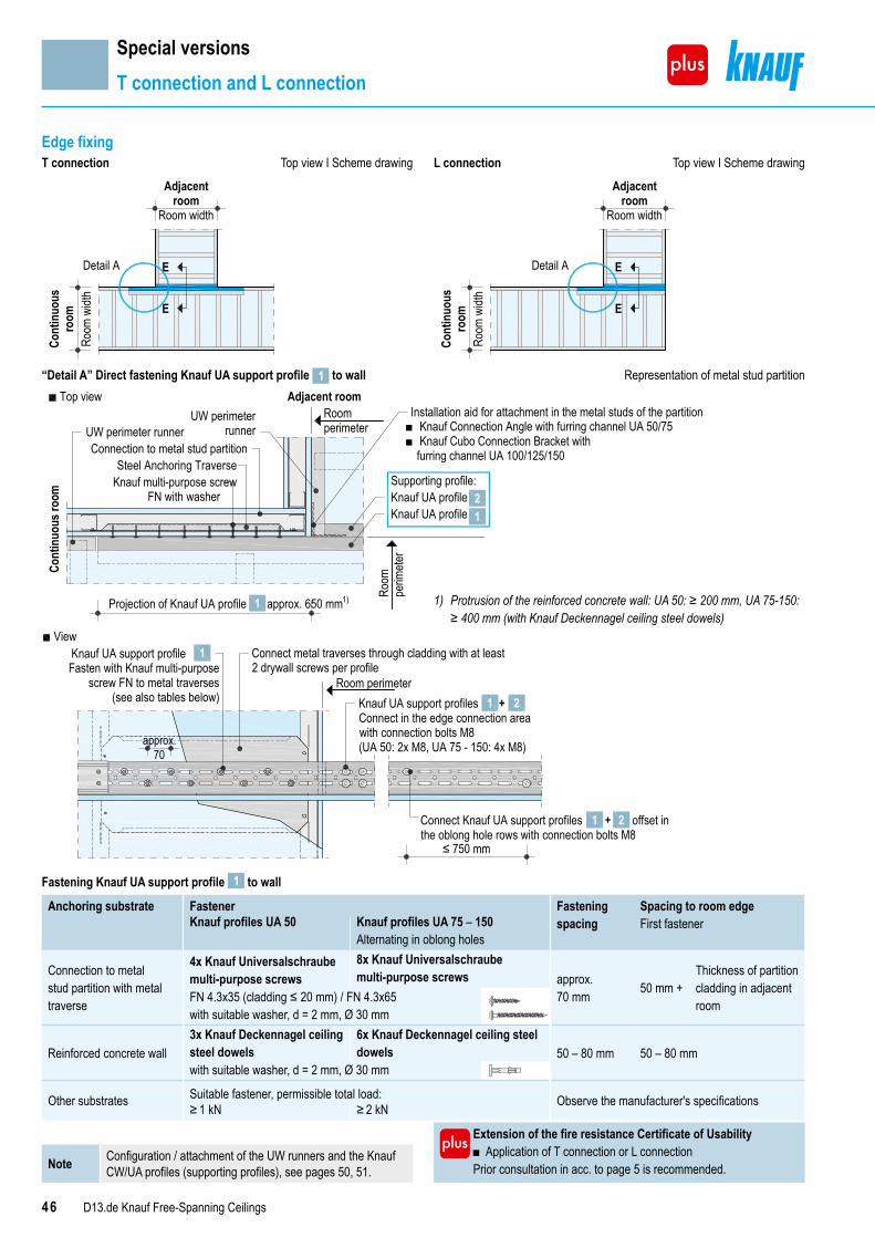
46 D13.de Knauf Free-Spanning Ceilings
Special versionsT connection and L connection
Edge fixingT connection Top view I Scheme drawing L connection Top view I Scheme drawing
Adjacentroom
Room width
Room
widt
h
Cont
inuo
usro
om E
EDetail A
Room
widt
h
Cont
inuo
usro
om
Adjacentroom
Room width
E
EDetail A
“Detail A” Direct fastening Knauf UA support profile 1 to wall Representation of metal stud partition
Cont
inuo
us ro
om
Adjacent room
Projection of Knauf UA profile approx. 650 mm1)
Knauf UA profileKnauf UA profile
Supporting profile:
Connection to metal stud partitionSteel Anchoring Traverse
Knauf multi-purpose screwFN with washer
UW perimeter runner
Top view
1
21
Installation aid for attachment in the metal studs of the partition■ Knauf Connection Angle with furring channel UA 50/75■ Knauf Cubo Connection Bracket with
furring channel UA 100/125/150
UW perimeterrunner
Roomperimeter
Room
perim
eter
View
Room perimeter
+Connect Knauf UA support profiles offset inthe oblong hole rows with connection bolts M8
1 2
≤ 750 mm
approx.70
Knauf UA support profiles +Connect in the edge connection areawith connection bolts M8(UA 50: 2x M8, UA 75 - 150: 4x M8)
Knauf UA support profile Fasten with Knauf multi-purpose
screw FN to metal traverses(see also tables below)
Connect metal traverses through cladding with at least2 drywall screws per profile
1 2
1
Fastening Knauf UA support profile 1 to wall
Anchoring substrate Fastener Fastening spacing
Spacing to room edgeFirst fastenerKnauf profiles UA 50 Knauf profiles UA 75 – 150
Alternating in oblong holes
Connection to metal stud partition with metal traverse
4x Knauf Universalschraube multi-purpose screws
8x Knauf Universalschraube multi-purpose screws approx.
70 mm 50 mm + Thickness of partition cladding in adjacent roomFN 4.3x35 (cladding ≤ 20 mm) / FN 4.3x65
with suitable washer, d = 2 mm, Ø 30 mm
Reinforced concrete wall3x Knauf Deckennagel ceiling steel dowels
6x Knauf Deckennagel ceiling steel dowels 50 – 80 mm 50 – 80 mm
with suitable washer, d = 2 mm, Ø 30 mm
Other substrates Suitable fastener, permissible total load: Observe the manufacturer's specifications≥ 1 kN ≥ 2 kN
1) Protrusion of the reinforced concrete wall: UA 50: ≥ 200 mm, UA 75-150: ≥ 400 mm (with Knauf Deckennagel ceiling steel dowels)
Extension of the fire resistance Certificate of Usability ■ Application of T connection or L connection
Prior consultation in acc. to page 5 is recommended.Note Configuration / attachment of the UW runners and the Knauf CW/UA profiles (supporting profiles), see pages 50, 51.
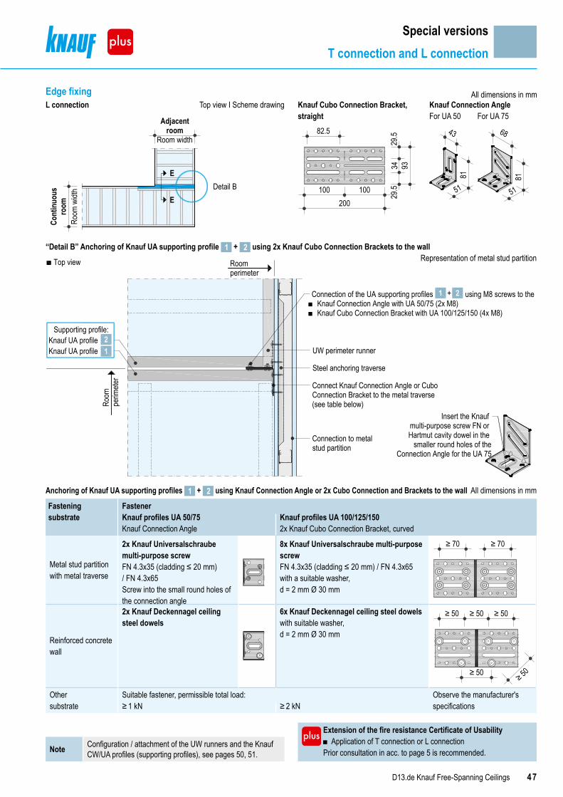
47D13.de Knauf Free-Spanning Ceilings
Special versionsT connection and L connection
Edge fixing All dimensions in mmL connection Top view I Scheme drawing Knauf Cubo Connection Bracket,
straightKnauf Connection Angle
Room
widt
h
Cont
inuo
usro
om
Adjacentroom
Room width
Detail B E
E
For UA 50 For UA 75
200100 100
82.5
9329.5
3429.5 43
81
51
81
68
51
“Detail B” Anchoring of Knauf UA supporting profile 1 + 2 using 2x Knauf Cubo Connection Brackets to the wall Representation of metal stud partition
Knauf UA profileKnauf UA profile
Supporting profile:
Top view
21
Connection of the UA supporting profiles using M8 screws to the■ Knauf Connection Angle with UA 50/75 (2x M8)■ Knauf Cubo Connection Bracket with UA 100/125/150 (4x M8)
+ 21
Roomperimeter
Room
perim
eter
UW perimeter runner
Steel anchoring traverse
Connect Knauf Connection Angle or Cubo Connection Bracket to the metal traverse (see table below)
Connection to metalstud partition
Insert the Knaufmulti-purpose screw FN or Hartmut cavity dowel in the
smaller round holes of the Connection Angle for the UA 75
Anchoring of Knauf UA supporting profiles 1 + 2 using Knauf Connection Angle or 2x Cubo Connection and Brackets to the wall All dimensions in mm
Fasteningsubstrate
FastenerKnauf profiles UA 50/75Knauf Connection Angle
Knauf profiles UA 100/125/1502x Knauf Cubo Connection Bracket, curved
Metal stud partition with metal traverse
2x Knauf Universalschraube multi-purpose screwFN 4.3x35 (cladding ≤ 20 mm)/ FN 4.3x65Screw into the small round holes of the connection angle
8x Knauf Universalschraube multi-purpose screwFN 4.3x35 (cladding ≤ 20 mm) / FN 4.3x65with a suitable washer, d = 2 mm Ø 30 mm
≥ 70 ≥ 70
Reinforced concrete wall
2x Knauf Deckennagel ceiling steel dowels
6x Knauf Deckennagel ceiling steel dowelswith suitable washer, d = 2 mm Ø 30 mm
≥ 50 ≥ 50
≥ 50
≥ 50
≥ 50
Other substrate
Suitable fastener, permissible total load: Observe the manufacturer's specifications≥ 1 kN ≥ 2 kN
Extension of the fire resistance Certificate of Usability ■ Application of T connection or L connection
Prior consultation in acc. to page 5 is recommended.Note Configuration / attachment of the UW runners and the Knauf CW/UA profiles (supporting profiles), see pages 50, 51.
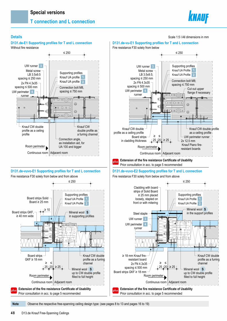
48 D13.de Knauf Free-Spanning Ceilings
Special versionsT connection and L connection
D131.de-E1 Supporting profiles for T and L connection D131.de-vu-E1 Supporting profiles for T and L connectionWithout fire resistance Fire resistance F30 solely from below
Extension of the fire resistance Certificate of Usability Prior consultation in acc. to page 5 recommended
D131.de-vuvo-E1 Supporting profiles for T and L connection D131.de-vuvo-E2 Supporting profiles for T and L connectionFire resistance F30 solely from below and from above Fire resistance F30 solely from below and from above
Extension of the fire resistance Certificate of Usability Prior consultation in acc. to page 5 recommended
Extension of the fire resistance Certificate of Usability Prior consultation in acc. to page 5 recommended
Room perimeter
Continuous room Adjacent room
Metal screwLB 3.5x9.5
spacing ≤ 250 mm2x FN 4.3x35
spacing ≤ 500 mm
Knauf CW doubleprofile as a ceilingprofile
Knauf CWdouble profile asa furring channel
Connection angle,as installation aid, forUA 100 and bigger
Connection bolt M8,spacing ≤ 750 mm
≤ 250
3UW runner
UW perimeterrunner
4
Knauf UA profileKnauf UA profile
Supporting profiles
21
≥25
≤20 ≥ 25
≤ 250
Knauf CW doubleprofile as a ceiling profile
Board stripsin cladding thickness
Metal screwLB 3.5x9.5;
spacing ≤ 250 mm
Knauf CW double profileas a ceiling profile
Connection bolt M8;spacing ≤ 750 mm
Cut out upperflange if necessary
2x FN 4.3x35spacing ≤ 500 mm
Adjacent roomContinuous room
Room perimeter
UW perimeter runner 2x 12.5 mm Knauf Piano fire-resistant boards
Knauf UA ProfileKnauf UA Profile
Supporting profiles1
3UW runner
UW perimeterrunner
4
2
S
S
≥25
≤20 ≥ 25
≤ 250
≥ 10
Knauf CW doubleprofile as a furringchannel
Board stripsGKF ≥ 18 mm
Board strips GKF,≥ 40 mm wide
Mineral woolin supporting profiles
Board strips SolidBoard ≥ 25 mm
Mineral woolup to CW double profilefilled to full height
Adjacent roomContinuous room
Room perimeter
Knauf UA ProfileKnauf UA Profile
Supporting profiles12
S
S
Steel staple
Room perimeter
Continuous room Adjacent room
Mineral woolin the support profiles
Knauf CW doubleprofile as a furringchannel
Mineral woolup to CW double profilefilled to full height
Cladding with board strips of Solid Board
≥ 25 mm placed loosely, stapled on
front or with mitering
≤ 250
≥25
≤20 ≥ 25
≥ 18 mm Knauf fire-resistant board
2x FN 4.3x35spacing ≤ 500 mm
Board strips GKF ≥ 18 mm
Knauf UA ProfileKnauf UA Profile
Supporting profiles12
3UW runnerUW perimeter
runner4
Scale 1:5 I All dimensions in mmDetails
Note Observe the respective free-spanning ceiling design type: (see pages 8 to 13 and pages 16 to 19)

49D13.de Knauf Free-Spanning Ceilings
Special versionsT connection and L connection
K219.de-vu-E1 Supporting profiles for T and L connectionFire resistance F90 solely from below
Board stripsFireboard ≥ 20 mm
2x ≥ 20 mmKnauf Fireboard
≤ 250
≥25
≤20 ≥ 25
Metal screwLB 3.5x9.5
spacing ≤ 250 mm2x FN 4.3x35
spacing ≤ 500 mm
Connection Angle,as installation aid, forUA 100 and larger
Knauf CW doubleprofile as a furringchannel
Connection bolt M8,spacing ≤ 750 mm
Adjacent room
Room perimeter
Continuous room
UW perimeter runner 4
3UW runnerKnauf UA profileKnauf UA profile
Supporting profiles12
Extension of the fire resistance Certificate of Usability Prior consultation in acc. to page 5 recommended
K219.de-vuvo-E1 Supporting profiles for T and L connectionFire resistance F90 solely from below and from above
≤ 250
≥25
≤20 ≥ 25
Encasement with Fireboard ≥ 20 mmloosely applied, stapled at front
or with mitering
Board strips Fireboard ≥ 20 mm
2x FN 4.3x35 Spacing ≤ 312.5 mm
Connection bolt M8,spacing ≤ 750 mm
Metal screwLB 3.5x9.5
spacing ≤ 250 mm
Mineral woolup to CW double studprofile filled to full height
Mineral woolin the support profiles
Room perimeter
Continuous room Adjacent room
20 mm Fireboard S
S
Steel staple
Knauf UA profileKnauf UA profile
Supporting profiles12
3UW runnerUW perimeter runner 4
Extension of the fire resistance Certificate of Usability Prior consultation in acc. to page 5 recommended
Scale 1:5 I All dimensions in mmDetails
Note Observe the respective free-spanning ceiling design type: (see pages 8 to 13 and pages 16 to 19)
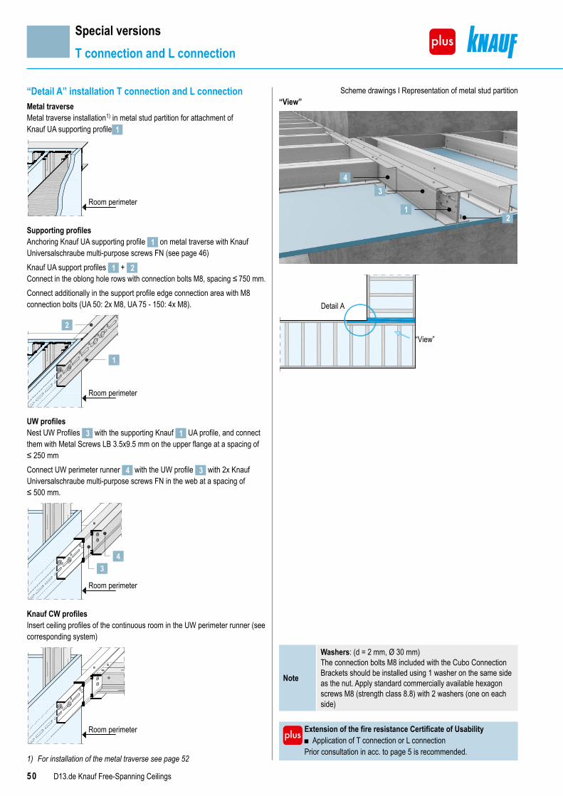
50 D13.de Knauf Free-Spanning Ceilings
Special versionsT connection and L connection
“Detail A” installation T connection and L connectionMetal traverseMetal traverse installation1) in metal stud partition for attachment of Knauf UA supporting profile 1
Room perimeter
Supporting profilesAnchoring Knauf UA supporting profile 1 on metal traverse with Knauf Universalschraube multi-purpose screws FN (see page 46)Knauf UA support profiles 1 + 2 Connect in the oblong hole rows with connection bolts M8, spacing ≤ 750 mm.Connect additionally in the support profile edge connection area with M8 connection bolts (UA 50: 2x M8, UA 75 - 150: 4x M8).
Room perimeter
2
1
UW profilesNest UW Profiles 3 with the supporting Knauf 1 UA profile, and connect them with Metal Screws LB 3.5x9.5 mm on the upper flange at a spacing of ≤ 250 mmConnect UW perimeter runner 4 with the UW profile 3 with 2x Knauf Universalschraube multi-purpose screws FN in the web at a spacing of ≤ 500 mm.
Room perimeter
43
Knauf CW profilesInsert ceiling profiles of the continuous room in the UW perimeter runner (see corresponding system)
Room perimeter
1) For installation of the metal traverse see page 52
Scheme drawings I Representation of metal stud partition“View”
4
1
3
2
“View”
Detail A
Extension of the fire resistance Certificate of Usability ■ Application of T connection or L connection
Prior consultation in acc. to page 5 is recommended.
Note
Washers: (d = 2 mm, Ø 30 mm) The connection bolts M8 included with the Cubo Connection Brackets should be installed using 1 washer on the same side as the nut. Apply standard commercially available hexagon screws M8 (strength class 8.8) with 2 washers (one on each side)
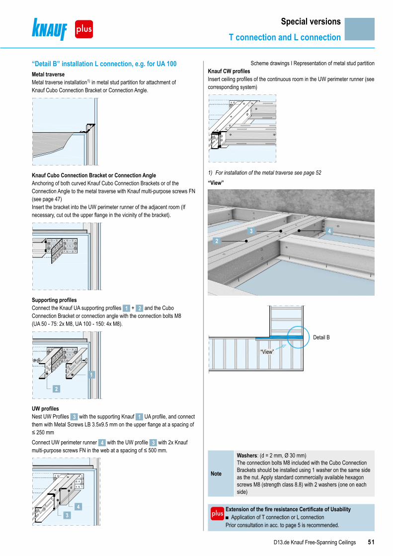
51D13.de Knauf Free-Spanning Ceilings
Special versionsT connection and L connection
Extension of the fire resistance Certificate of Usability ■ Application of T connection or L connection
Prior consultation in acc. to page 5 is recommended.
Note
Washers: (d = 2 mm, Ø 30 mm) The connection bolts M8 included with the Cubo Connection Brackets should be installed using 1 washer on the same side as the nut. Apply standard commercially available hexagon screws M8 (strength class 8.8) with 2 washers (one on each side)
“Detail B” installation L connection, e.g. for UA 100Metal traverseMetal traverse installation1) in metal stud partition for attachment ofKnauf Cubo Connection Bracket or Connection Angle.
Knauf Cubo Connection Bracket or Connection AngleAnchoring of both curved Knauf Cubo Connection Brackets or of the Connection Angle to the metal traverse with Knauf multi-purpose screws FN (see page 47)Insert the bracket into the UW perimeter runner of the adjacent room (If necessary, cut out the upper flange in the vicinity of the bracket).
Supporting profilesConnect the Knauf UA supporting profiles 1 + 2 and the Cubo Connection Bracket or connection angle with the connection bolts M8 (UA 50 - 75: 2x M8, UA 100 - 150: 4x M8).
1
2
UW profilesNest UW Profiles 3 with the supporting Knauf 1 UA profile, and connect them with Metal Screws LB 3.5x9.5 mm on the upper flange at a spacing of ≤ 250 mmConnect UW perimeter runner 4 with the UW profile 3 with 2x Knauf multi-purpose screws FN in the web at a spacing of ≤ 500 mm.
43
Scheme drawings I Representation of metal stud partitionKnauf CW profilesInsert ceiling profiles of the continuous room in the UW perimeter runner (see corresponding system)
1) For installation of the metal traverse see page 52
“View”
32
4
“View”
Detail B

52 D13.de Knauf Free-Spanning Ceilings
Installation of the metal traverse with connection of furring channel UA to metal stud partition or with an L/T connectionView Scheme drawings I All dimensions in mm
Knauf CW stud
Spacing of studs 625 (grid spacing)
Metal traverse size 620
290
Metal traverse
Metal traverse withKnauf CW stud crimped
with a stud crimper
UW perimeter runner
Additionalscrew fastening of themetal traversevia screw fasteningof the cladding
Horizontal sections
Knauf CW studMetal traverseUW perimeter runner
Knauf board
InstallationCrimp the metal traverse made of galvanized sheet metal on the side to the CW studs using the stud crimper.Additional screw fastening of the metal traverse using the screw fastening of the cladding (min. 2 to 3 screw fastening connections). Reduction of the screw spacing for the cladding may be prudent.
Special versionsMetal traverse

53D13.de Knauf Free-Spanning Ceilings
Special versionsCentre suspension
Centre suspension with UA centre suspension
Centre suspension with threaded rod
■ Centre suspensions facilitate larger ceiling span widths. ■ Further information on request.
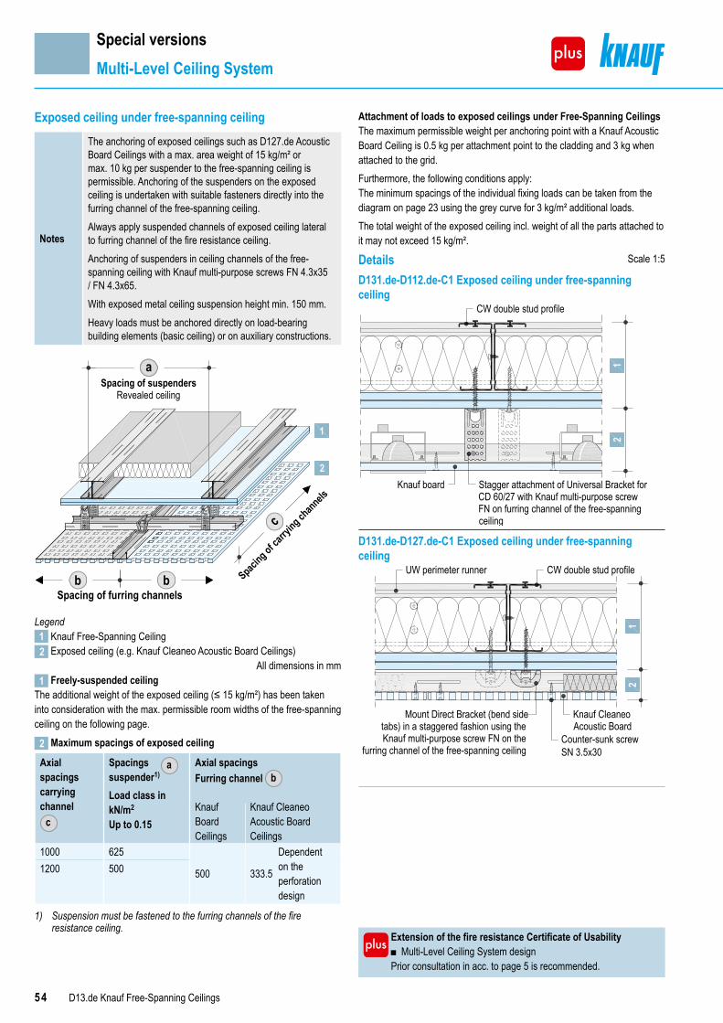
54 D13.de Knauf Free-Spanning Ceilings
Special versionsMulti-Level Ceiling System
Exposed ceiling under free-spanning ceiling
Notes
The anchoring of exposed ceilings such as D127.de Acoustic Board Ceilings with a max. area weight of 15 kg/m² or max. 10 kg per suspender to the free-spanning ceiling is permissible. Anchoring of the suspenders on the exposed ceiling is undertaken with suitable fasteners directly into the furring channel of the free-spanning ceiling. Always apply suspended channels of exposed ceiling lateral to furring channel of the fire resistance ceiling.Anchoring of suspenders in ceiling channels of the free-spanning ceiling with Knauf multi-purpose screws FN 4.3x35 / FN 4.3x65.With exposed metal ceiling suspension height min. 150 mm.Heavy loads must be anchored directly on load-bearing building elements (basic ceiling) or on auxiliary constructions.
Spacing of furring channelsb b Spaci
ng of carry
ing channels
c
Spacing of suspendersRevealed ceiling
a
1
2
Legend1 Knauf Free-Spanning Ceiling2 Exposed ceiling (e.g. Knauf Cleaneo Acoustic Board Ceilings)
All dimensions in mm1 Freely-suspended ceiling
The additional weight of the exposed ceiling (≤ 15 kg/m²) has been taken into consideration with the max. permissible room widths of the free-spanning ceiling on the following page.
2 Maximum spacings of exposed ceiling
Axial spacingscarrying channel
c
Spacingssuspender1)
Axial spacingsFurring channel b
Load class in kN/m2
Up to 0.15Knauf Board Ceilings
Knauf Cleaneo Acoustic Board Ceilings
1000 625
500 333.5
Dependent on the perforation design
1200 500
1) Suspension must be fastened to the furring channels of the fire resistance ceiling.
a
Extension of the fire resistance Certificate of Usability ■ Multi-Level Ceiling System design
Prior consultation in acc. to page 5 is recommended.
Attachment of loads to exposed ceilings under Free-Spanning CeilingsThe maximum permissible weight per anchoring point with a Knauf Acoustic Board Ceiling is 0.5 kg per attachment point to the cladding and 3 kg when attached to the grid. Furthermore, the following conditions apply:The minimum spacings of the individual fixing loads can be taken from the diagram on page 23 using the grey curve for 3 kg/m² additional loads.The total weight of the exposed ceiling incl. weight of all the parts attached to it may not exceed 15 kg/m².
Details Scale 1:5
D131.de-D112.de-C1 Exposed ceiling under free-spanning ceiling
Knauf board
CW double stud profile
Stagger attachment of Universal Bracket for CD 60/27 with Knauf multi-purpose screw FN on furring channel of the free-spanning ceiling
21
D131.de-D127.de-C1 Exposed ceiling under free-spanning ceiling
CW double stud profile
Mount Direct Bracket (bend sidetabs) in a staggered fashion using the Knauf multi-purpose screw FN on the
furring channel of the free-spanning ceiling
Knauf CleaneoAcoustic Board
Counter-sunk screw SN 3.5x30
12
UW perimeter runner

55D13.de Knauf Free-Spanning Ceilings
Special versionsMulti-Level Ceiling System
Metal ― grid free-spanning for multi-level ceilingD131.de Knauf Free-Spanning Ceiling without fire resistance
Scheme drawing
1 Knauf Free-Spanning Ceiling2 Exposed ceiling
Knauf profiles
Maximum room width1)
Knauf Wallboard
Diamant Silentboard Silentboard + Diamant
12.5 mm 12.5 mm 15 mm 2x 12.5 mm 12.5 mm 12.5 + 12.5 mmm m m m m m
21
Knauf CW double profile metal gauge 0.6 mm2x CW 50 2.45 2.40 2.35 2.20 2.40 2.252x CW 75 3.05 3.00 2.95 2.75 3.00 2.802x CW 100 3.60 3.50 3.45 3.252) 3.55 3.302)
2x CW 125 4.05 3.95 3.90 3.652) 4.002) 3.752)
2x CW 150 4.50 4.402) 4.302) 4.052) 4.452) 4.153)
Knauf UA double profile metal gauge 2.0 mm2x UA 50 2.95 2.85 2.80 2.65 2.90 2.702)
2x UA 75 3.65 3.55 3.50 3.302) 3.602) 3.402)
2x UA 100 4.302) 4.202) 4.152) 3.903) 4.252) 4.003)
2x UA 125 4.852) 4.752) 4.703) 4.453) 4.803) 4.553)
2x UA 150 5.403) 5.253) 5.203) 4.953) 5.353) 5.053)
Permissible wall connections see page 8D131.de Knauf Free-Spanning Ceiling fire resistance F30 solely from below
Scheme drawing
1 Knauf Free-Spanning Ceiling2 Exposed ceiling
Knauf profiles
Maximum room width1)
Knauf Piano fire-resistant board
Knauf Feuer-schutzplatte fire-resistant board
Diamant Silentboard + Diamant
2x 12.5 mm 18 mm 18 mm 2x 12.5 mm 12.5 + 12.5 mmm m m m m
21
Knauf CW double profile metal gauge 0.6 mm2x CW 50 2.25 2.20 2.15 2.20 2.252x CW 75 2.80 2.80 2.70 2.75 2.802x CW 100 3.30 3.25 3.20 3.252) 3.302)
2x CW 125 3.752) 3.70 3.65 3.652) 3.752)
2x CW 150 4.152) 4.102) 4.052) 4.052) 4.153)
Knauf UA double profile metal gauge 2.0 mm 2x UA 50 2.70 2.70 2.65 2.65 2.702)
2x UA 75 3.402) 3.35 3.30 3.302) 3.402)
2x UA 100 4.002) 3.952) 3.902) 3.903) 4.003)
2x UA 125 4.553) 4.502) 4.402) 4.453) 4.553)
2x UA 150 5.053) 5.003) 4.903) 4.953) 5.053)
Permissible wall connections see page 101) Maximum room widths: Including additional loads (3 kg/m2) for insulation
layers necessary for fire resistance and sound insulation measures or fixing loads as well as 15 kg/m2 for the entire load of the multi-level ceiling system.
2) Required cladding thickness with flanking metal stud partitions on the side of the supporting connection: ≥ 18 mm Knauf Boards / ≥ 15 mm Diamant
3) Metal traverse required with flanking metal stud partitions. See page 52 for installation.
Extension of the fire resistance Certificate of Usability ■ Multi-Level Ceiling System design
Prior consultation in acc. to page 5 is recommended.

56 D13.de Knauf Free-Spanning Ceilings
Special versionsMulti-Level Ceiling System
Metal ― grid free-spanning for multi-level ceilingD131.de Knauf free-spanning ceiling fire resistance F30 solely from below and from above
Scheme drawing
1 Knauf Free-Spanning Ceiling2 Exposed ceiling
Knauf profiles
Maximum room width1)
Knauf Piano fire-resistant board
Knauf Feuer-schutzplatte fire-resistant board
Diamant Silentboard + Diamant
2x 12.5 mm 18 mm 18 mm 2x 12.5 mm 12.5 + 12.5 mmm m m m m
21
Knauf CW double profile metal gauge 0.6 mm2x CW 50 1.90 1.85 1.80 1.80 1.902x CW 75 2.40 2.35 2.25 2.30 2.402x CW 100 2.85 2.80 2.70 2.75 2.902)
2x CW 125 3.302) 3.20 3.10 3.152) 3.302)
Knauf UA double profile metal gauge 2.0 mm 2x UA 50 2.65 2.60 2.60 2.60 2.652)
2x UA 75 3.302) 3.25 3.202) 3.252) 3.303)
2x UA 100 3.903) 3.852) 3.802) 3.853) 3.903)
2x UA 125 4.453) 4.402) 4.303) 4.353) 4.453)
Permissible wall connections see page 12D131.de Knauf free-spanning ceiling fire resistance F60 solely from below and from above
Scheme drawing
1 Knauf Free-Spanning Ceiling2 Exposed ceiling
Knauf profiles
Maximum room width1)
Knauf Piano fire-resistant board Diamant2x 12.5 mm 2x 12.5 mmm m
12
Knauf CW double profile metal gauge 0.6 mm2x CW 50 2.10 2.052x CW 75 2.65 2.552)
2x CW 100 3.102) 3.002)
2x CW 125 3.502) 3.403)
2x CW 150 3.902) 3.803)
Knauf UA double profile metal gauge 2.0 mm 2x UA 50 2.552) 2.502)
2x UA 75 3.202) 3.102)
2x UA 100 3.753) 3.702)
2x UA 125 4.303) 4.202)
2x UA 150 4.753) 4.653)
Permissible wall connections see page 14
1) Maximum room widths: Including additional loads (3 kg/m2) for insulation layers necessary for fire resistance and sound insulation measures or fixing loads as well as 15 kg/m2 for the entire load of the multi-level ceiling system.
2) Required cladding thickness with flanking metal stud partitions on the side of the supporting connection: ≥ 18 mm Knauf Boards / ≥ 15 mm Diamant
3) Metal traverse required with flanking metal stud partitions. See page 52 for installation.
Extension of the fire resistance Certificate of Usability ■ Multi-Level Ceiling System design
Prior consultation in acc. to page 5 is recommended.

57D13.de Knauf Free-Spanning Ceilings
Special versionsMulti-Level Ceiling System
Metal ― grid free-spanning for multi-level ceilingK219.de Knauf Free-Spanning Fireboard Ceiling A1 fire protection F90 solely from below
Scheme drawing
1 Knauf Free-Spanning Ceiling2 Exposed ceiling
Knauf profiles Maximum room width1)
Fireboard2x 20 mmm
21
Knauf CW double profile metal gauge 0.6 mm2x CW 50 2.002x CW 75 2.502x CW 100 2.952)
2x CW 125 3.352)
2x CW 150 3.752)
Knauf UA double profile metal gauge 2.0 mm2x UA 50 2.452x UA 75 3.052)
2x UA 100 3.653)
2x UA 125 4.153)
2x UA 150 4.603)
Permissible wall connections see page 16K219.de Knauf Free-Spanning Fireboard ceiling A1 fire resistance F90 solely from below and from above
Scheme drawing
1 Knauf Free-Spanning Ceiling2 Exposed ceiling
Knauf profiles Maximum room width1)
Fireboard20 mmm
21
Knauf CW double profile metal gauge 0.6 mm2x CW 50 1.952x CW 75 2.502x CW 100 2.902)
2x CW 125 3.302)
Knauf UA double profile metal gauge 2.0 mm2x UA 50 2.402x UA 75 3.002)
2x UA 100 3.553)
2x UA 125 4.053)
Permissible wall connections see page 18
1) Maximum room widths: Including additional loads (3 kg/m2) for insulation layers necessary for fire resistance and sound insulation measures or fixing loads as well as 15 kg/m2 for the entire load of the multi-level ceiling system.
2) Required cladding thickness with flanking metal stud partitions on the side of the supporting connection: ≥ 18 mm Knauf Boards / ≥ 15 mm Diamant
3) Metal traverse required with flanking metal stud partitions. See page 52 for installation.
Extension of the fire resistance Certificate of Usability ■ Multi-Level Ceiling System design
Prior consultation in acc. to page 5 is recommended.
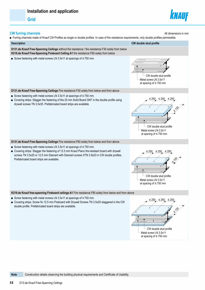
58 D13.de Knauf Free-Spanning Ceilings
CW furring channels ■ Furring channels made of Knauf CW Profiles as single or double profiles. In case of fire resistance requirements, only double profiles permissible.
Description CW double stud profile
D131.de Knauf Free-Spanning Ceilings without fire resistance / fire resistance F30 solely from belowK219.de Knauf Free-Spanning Fireboard Ceiling A1 fire resistance F90 solely from below
■ Screw fastening with metal screws LN 3.5x11 at spacings of ≤ 750 mm.
Metal screw LN 3.5x11at spacing of ≤ 750 mm
CW double stud profile
D131.de Knauf Free-Spanning Ceilings Fire resistance F30 solely from below and from above ■ Screw fastening with metal screws LN 3.5x11 at spacings of ≤ 750 mm. ■ Covering strips: Stagger the fastening of the 25 mm Solid Board GKF in the double profile using drywall screws TN 3.5x35. Prefabricated board strips are available.
Metal screw LN 3.5x11at spacing of ≤ 750 mm
CW double stud profile
≤ 250 ≤ 250 ≤ 250
≥ 120
D131.de Knauf Free-Spanning Ceilings Fire resistance F60 solely from below and from above ■ Screw fastening with metal screws LN 3.5x11 at spacings of ≤ 750 mm. ■ Covering strips: Stagger the fastening of 12.5 mm Knauf Piano fire-resistant board with drywall screws TN 3.5x25 or 12.5 mm Diamant with Diamant screws XTN 3.9x23 in CW double profiles. Prefabricated board strips are available.
≥ 100
≤ 250 ≤ 250 ≤ 250
Metal screw LN 3.5x11at spacing of ≤ 750 mm
CW double stud profile
K219.de Knauf free-spanning Fireboard ceilings A1 Fire resistance F90 solely from below and from above ■ Screw fastening with metal screws LN 3.5x11 at spacings of ≤ 750 mm. ■ Covering strips: Screw fix 12.5 mm Fireboard with Drywall Screws TN 3.5x25 staggered in the CW double profile. Prefabricated board strips are available.
≤ 250 ≤ 250 ≤ 250
≥ 120
Metal screw LN 3.5x11at spacing of ≤ 750 mm
CW double stud profile
Installation and applicationGrid
All dimensions in mm
Note Construction details observing the building physical requirements and Certificate of Usability.
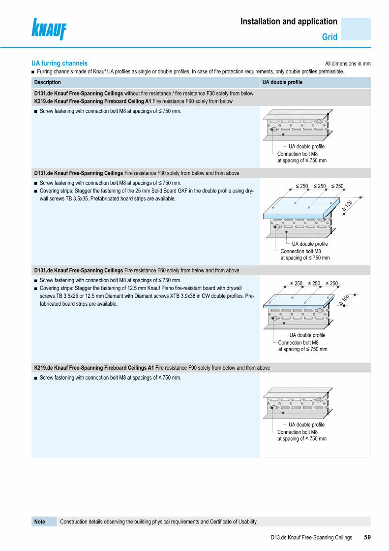
59D13.de Knauf Free-Spanning Ceilings
Installation and applicationGrid
All dimensions in mm
Note Construction details observing the building physical requirements and Certificate of Usability.
UA furring channels ■ Furring channels made of Knauf UA profiles as single or double profiles. In case of fire protection requirements, only double profiles permissible.
Description UA double profile
D131.de Knauf Free-Spanning Ceilings without fire resistance / fire resistance F30 solely from belowK219.de Knauf Free-Spanning Fireboard Ceiling A1 Fire resistance F90 solely from below
■ Screw fastening with connection bolt M8 at spacings of ≤ 750 mm.
Connection bolt M8at spacing of ≤ 750 mm
UA double profile
D131.de Knauf Free-Spanning Ceilings Fire resistance F30 solely from below and from above ■ Screw fastening with connection bolt M8 at spacings of ≤ 750 mm. ■ Covering strips: Stagger the fastening of the 25 mm Solid Board GKF in the double profile using dry-wall screws TB 3.5x35. Prefabricated board strips are available.
≤ 250 ≤ 250 ≤ 250
≥ 120
Connection bolt M8at spacing of ≤ 750 mm
UA double profile
D131.de Knauf Free-Spanning Ceilings Fire resistance F60 solely from below and from above ■ Screw fastening with connection bolt M8 at spacings of ≤ 750 mm. ■ Covering strips: Stagger the fastening of 12.5 mm Knauf Piano fire-resistant board with drywall screws TB 3.5x25 or 12.5 mm Diamant with Diamant screws XTB 3.9x38 in CW double profiles. Pre-fabricated board strips are available.
≤ 250 ≤ 250 ≤ 250
≥ 100
Connection bolt M8at spacing of ≤ 750 mm
UA double profile
K219.de Knauf Free-Spanning Fireboard Ceilings A1 Fire resistance F90 solely from below and from above ■ Screw fastening with connection bolt M8 at spacings of ≤ 750 mm.
Connection bolt M8at spacing of ≤ 750 mm
UA double profile
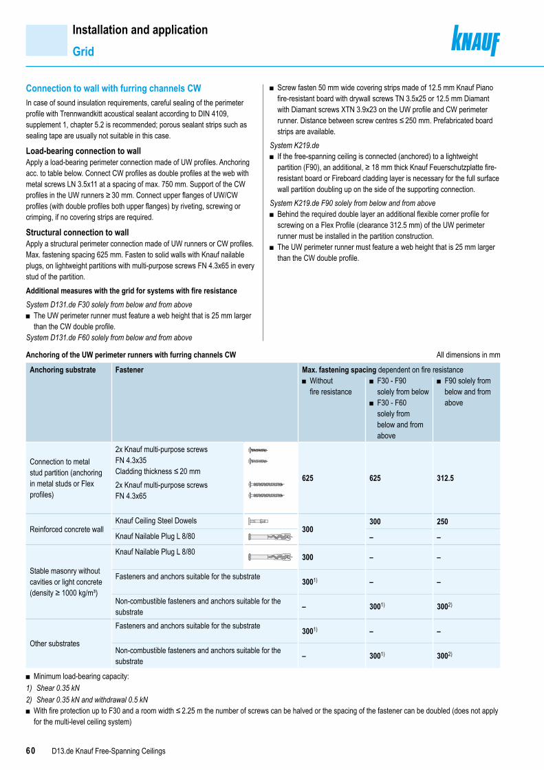
60 D13.de Knauf Free-Spanning Ceilings
Connection to wall with furring channels CWIn case of sound insulation requirements, careful sealing of the perimeter profile with Trennwandkitt acoustical sealant according to DIN 4109, supplement 1, chapter 5.2 is recommended; porous sealant strips such as sealing tape are usually not suitable in this case.
Load-bearing connection to wallApply a load-bearing perimeter connection made of UW profiles. Anchoring acc. to table below. Connect CW profiles as double profiles at the web with metal screws LN 3.5x11 at a spacing of max. 750 mm. Support of the CW profiles in the UW runners ≥ 30 mm. Connect upper flanges of UW/CW profiles (with double profiles both upper flanges) by riveting, screwing or crimping, if no covering strips are required.
Structural connection to wallApply a structural perimeter connection made of UW runners or CW profiles. Max. fastening spacing 625 mm. Fasten to solid walls with Knauf nailable plugs, on lightweight partitions with multi-purpose screws FN 4.3x65 in every stud of the partition.Additional measures with the grid for systems with fire resistanceSystem D131.de F30 solely from below and from above
■ The UW perimeter runner must feature a web height that is 25 mm larger than the CW double profile.
System D131.de F60 solely from below and from above
Anchoring of the UW perimeter runners with furring channels CW All dimensions in mm
Anchoring substrate Fastener Max. fastening spacing dependent on fire resistance ■ Without fire resistance
■ F30 - F90 solely from below
■ F30 - F60 solely from below and from above
■ F90 solely from below and from above
Connection to metal stud partition (anchoring in metal studs or Flex profiles)
2x Knauf multi-purpose screws FN 4.3x35Cladding thickness ≤ 20 mm
625 625 312.52x Knauf multi-purpose screws FN 4.3x65
Reinforced concrete wallKnauf Ceiling Steel Dowels
300300 250
Knauf Nailable Plug L 8/80 – –
Stable masonry without cavities or light concrete (density ≥ 1000 kg/m³)
Knauf Nailable Plug L 8/80 300 – –
Fasteners and anchors suitable for the substrate 3001) – –
Non-combustible fasteners and anchors suitable for the substrate – 3001) 3002)
Other substrates
Fasteners and anchors suitable for the substrate 3001) – –
Non-combustible fasteners and anchors suitable for the substrate – 3001) 3002)
■ Minimum load-bearing capacity:1) Shear 0.35 kN2) Shear 0.35 kN and withdrawal 0.5 kN
■ With fire protection up to F30 and a room width ≤ 2.25 m the number of screws can be halved or the spacing of the fastener can be doubled (does not apply for the multi-level ceiling system)
Installation and applicationGrid
■ Screw fasten 50 mm wide covering strips made of 12.5 mm Knauf Piano fire-resistant board with drywall screws TN 3.5x25 or 12.5 mm Diamant with Diamant screws XTN 3.9x23 on the UW profile and CW perimeter runner. Distance between screw centres ≤ 250 mm. Prefabricated board strips are available.
System K219.de ■ If the free-spanning ceiling is connected (anchored) to a lightweight partition (F90), an additional, ≥ 18 mm thick Knauf Feuerschutzplatte fire-resistant board or Fireboard cladding layer is necessary for the full surface wall partition doubling up on the side of the supporting connection.
System K219.de F90 solely from below and from above ■ Behind the required double layer an additional flexible corner profile for screwing on a Flex Profile (clearance 312.5 mm) of the UW perimeter runner must be installed in the partition construction.
■ The UW perimeter runner must feature a web height that is 25 mm larger than the CW double profile.

61D13.de Knauf Free-Spanning Ceilings
Connection to wall with furring channels CWD131.de Knauf Free-Spanning Ceilings Without fire resistance
≥ 30
≤ 625 2x Knauf multi-purpose
screws FN
CW single profile or CWdouble profile
Rivet / crimp
UW perimeterrunner
■ Connect Knauf CW profiles as single or double profiles (per flange) with UW runner by riveting, crimping or screwing with Knauf Metal Screws LN 3.5x11 mm.
D131.de Knauf Free-Spanning Ceiling Fire resistance F30 solely from below
≤ 625
≥ 30
CW double stud profile
2x Knauf UniversalschraubeFN multi-purpose screws
Schnellbauschraube TNdrywall screw
UW perimeterrunner
D131.de Knauf Free-Spanning Ceilings Fire resistance F30 solely from below and from above
≥ 30
≤ 625
CW double stud
2x Knauf UniversalschraubeFN multi-purpose screws
Cover strips
SchnellbauschraubeTN drywall screw
UW perimeterrunner
Installation and applicationGrid
D131.de Knauf Free-Spanning Ceilings Fire resistance F60 solely from below / solely from below and
from above
≥ 30
≤ 625
CW double stud profile
2x Knauf UniversalschraubeFN multi-purpose screws
Cover strips
Cover board
S D131 R d hl BS F60
UW perimeterrunner
K219.de Knauf Free-Spanning Fireboard Ceiling A1Fire resistance F90 solely from below
≤ 625
≥ 30
2x Knauf UniversalschraubeFN multi-purpose screw
SchnellbauschraubeTN drywall screw
CW double stud profileUW perim. runnerAdditional 20 mm Fireboard
K219.de Knauf Free-Spanning Fireboard Ceiling A1 Fire resistance F90 solely from below and from above
≥ 30
≤ 312.
5
≤ 312.
5
Flexcorner profile
2x Knauf Universalschraubemulti-purpose screw;a ≤ 312.5 mm
Cover board
SchnellbauschraubeTN 3.5x25 drywall screw
UW perim. runner CW double stud profile withFireboard cover stripsAdditional 20 mm
Fireboard
Extension of the fire resistance Certificate of Usability ■ Connection to lightweight partition
Prior consultation in acc. to page 5 is recommended.
Note For anchoring of connection to wall with furring channel CW, see page 60

62 D13.de Knauf Free-Spanning Ceilings
Connection to wall with furring channels UAIn case of sound insulation requirements, careful sealing of the perimeter profile with Trennwandkitt acoustical sealant according to DIN 4109, supplement 1, chapter 5.2 is recommended; porous sealant strips such as sealing tape are usually not suitable in this case.
Load-bearing connection to wallApply the load-bearing connection to wall using perimeter runners made of UW runners as backing as well as with Knauf Connection Angle or Cubo Connection Bracket. Anchoring acc. to table below.Insert the UA furring channel into the UW runner and anchor to the wall with Knauf Connection Angle or Knauf Cubo Connection Bracket in accordance with the table below.
Structural connection to wallApply a structural perimeter connection made of UA Profiles. Max. fastening spacing 625 mm. Fasten to solid walls with fasteners that are suitable for the substrate, on lightweight partitions with multi-purpose screws FN 4.3x65 in every stud of the partition.
Connection of the UW perimeter runners of the UA furring channels (backing of the load-bearing connection) All dimensions in mm
Anchoring substrate Fasteners for UW perimeter runners Max. fastening spacing
Metal stud partitions (anchoring in metal studs or Flex Profiles)
1x Knauf multi-purpose screws FN 4.3x35 Cladding thickness ≤ 20 mm
6251x Knauf multi-purpose screws FN 4.3x65
Reinforced concrete wall or stable masonry without cavities or light concrete (density ≥ 1000 kg/m³)
1x Knauf Ceiling Steel Dowels 1x Knauf Nailable Plug L 8/80
This profile serves only for fastening as well as backing of the perimeter connection of the cladding and does not have a load-bearing function.
Connection of the Knauf Connection Angle or Cubo Connection Bracket to the load-bearing connection
Fasteningsubstrate
FastenersKnauf Connection Angle with UA 50/75 Knauf Cubo Connection Brackets with UA 100/125/150
Metal stud partition
Furring channel connection Perimeter profile connection Furring channel connection Perimeter profile connection
Connection angle Connection angleS A hl i k l
≥ 70 ≥ 70
Bracket
S V bi d i k l A
≥ 70
BracketS Verbind winkel R2x 2x 4x 2x
Knauf Hartmut cavity dowel (cladding thickness ≤ 40 mm) Knauf Hartmut cavity dowel (cladding thickness ≤ 40 mm)Screw fastening through two small circular holes With suitable washer, d = 2 mm, Ø 30 mm
or or2x 2x 4x 2xKnauf multi-purpose screw FN 4.3x65 mm with metal traverse Knauf multi-purpose screw FN 4.3x65 mm with metal traverseScrew fastening through two small circular holes With suitable washer, d = 2 mm, Ø 30 mm
Reinforced concrete wall
Furring channel connection Perimeter profile connection Furring channel connection Perimeter profile connection
Connection angleS A hl i k l UA
Connection angleS A hl i k l
≥ 50 ≥ 50 ≥ 50
≥ 50
≥ 50
Bracket ≥ 50
≥ 50
Bracket
2x 2x 4x 2xKnauf Ceiling Steel Dowels Knauf Ceiling Steel Dowels
With suitable washer, d = 2 mm, Ø 30 mm
Other substrate Non-combustible fasteners suitable for the substrate featuring a minimum load-bearing capacity of 0.5 kN against shear and withdrawal. Observe the manufacturer's specifications.
Installation and applicationGrid
Additional measures with the grid for systems with fire resistanceSystem D131.de F30 solely from below and from above
■ The UW perimeter runner must feature a web height that is 25 mm larger than the UA double profile.
System D131.de F60 solely from below and from above ■ Screw fasten 50 mm wide covering strips made of 12.5 mm Knauf Piano fire-resistant board with drywall screws TB 3.5x25 or 12.5 mm Diamant with Diamant screws XTB 3.9x38 on the UW profile and UA perimeter runner. Distance between screw centres ≤ 250 mm. Prefabricated board strips are available.
System K219.de ■ If the free-spanning ceiling is connected (anchored) to a lightweight partition (F90), an additional, ≥ 18 mm thick Knauf Feuerschutzplatte fire-resistant board or Fireboard cladding layer is necessary for the full surface wall partition doubling up on the side of the supporting connection.
■ With fire resistance from above: Behind the required double layer an addi-tional flexible corner profile for screwing on a Flex Profile (clearance 312.5 mm) of the UW perimeter runner must be installed in the partition construction.
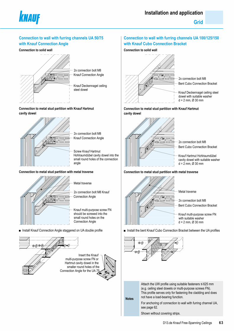
63D13.de Knauf Free-Spanning Ceilings
Installation and applicationGrid
Connection to wall with furring channels UA 50/75 with Knauf Connection AngleConnection to solid wall
2x connection bolt M8 Knauf Connection Angle
Knauf Deckennagel ceiling steel dowel
Connection to metal stud partition with Knauf Hartmut cavity dowel
2x connection bolt M8Knauf Connection Angle
Screw Knauf Hartmut Hohlraumdübel cavity dowel into the small round holes of the connection angle
Connection to metal stud partition with metal traverse
■
Metal traverse
2x connection bolt M8 Knauf Connection Angle
Knauf multi-purpose screw FN should be screwed into the small round holes on the Connection Angle
Install Knauf Connection Angle staggered on UA double profile
Insert the Knaufmulti-purpose screw FN or Hartmut cavity dowel in the
smaller round holes of the Connection Angle for the UA 75
Connection to wall with furring channels UA 100/125/150 with Knauf Cubo Connection BracketConnection to solid wall
Bent Cubo Connection Bracket
Knauf Deckennagel ceiling steeldowel with suitable washerd = 2 mm, Ø 30 mm
2x connection bolt M8
Connection to metal stud partition with Knauf Hartmut cavity dowel
Knauf Hartmut Hohlraumdübelcavity dowel with suitable washerd = 2 mm, Ø 30 mm
2x connection bolt M8Bent Cubo Connection Bracket
Connection to metal stud partition with metal traverse
■
Knauf multi-purpose screw FNwith suitable washerd = 2 mm, Ø 30 mm
2x connection bolt M8
Metal traverse
Bent Cubo Connection Bracket
Install the bent Knauf Cubo Connection Bracket between the UA profiles
Notes
Attach the UW profile using suitable fasteners ≤ 625 mm (e.g. ceiling steel dowels or multi-purpose screws FN). This profile serves only for fastening the cladding and does not have a load-bearing function.For anchoring of connection to wall with furring channel UA, see page 62.Shown without covering strips.

64 D13.de Knauf Free-Spanning Ceilings
Insulation layerLay insulation material required for sound insulation and fire resistance purposes to the full surface and butt jointed between the furring channels (on the cladding).
Cladding installation ■ Commence with the fixing of the boards in the board centre or on the board corner to avoid buckling. ■ Every board layer should be pushed firmly onto the grid and attached as an independent layer.
Top side covering layerSystem D131.de F60 solely from below and from aboveApply a loose top covering layer on the double profiles made of Knauf Piano fire-resistant board 12.5 mm or Diamant and overlap the longitudinal joints by at least 50 mm. Arrange the front edge joints at the centre of the double profiles.System K219.de F90 solely from below and from above
■ Apply a loose top covering layer made of double profiles made of Fireboard 20 mm with tight joints.
Installation and applicationInsulation layer I Top side covering layer I Cladding
Installation schemesKnauf boards – lateral cladding application Scheme drawings I All dimensions in mm
1250
1250
1250
1250
Boar
d widt
h
1st board layer
2nd board layer
Long edge
Fron
t edg
e
Boar
d widt
h
625
625
Boar
d widt
h
1250
1250
1st board layer
2nd board layer
Long edge
Fron
t edg
e
Boar
d widt
h
Board width1st layer: 1250 mm e.g. Knauf Piano fire-resistant board GKF 12.52nd layer: 1250 mm e.g. Knauf Piano fire-resistant board GKF 12.5
■ Apply Knauf boards lateral to the furring channels (e.g. double profiles). ■ Arrange the board joints on the furring channels (stagger by at least 400 mm, with fire resistance class F60 min. 1000 mm within a layer and min. 500 mm between the first and second layer).
■ Stagger the front edge joints between board layers. ■ Stagger the long joints between the board layers by at least half a board width.
Board width1st layer: 625 mm e.g. Silentboard GKF 12.52nd layer: 1250 mm e.g. Diamant GKF 12.5
■ Apply Knauf boards lateral to the furring channels (e.g. double profiles). ■ Arrange the board joints on the furring channels (stagger by at least 400 mm).
■ Stagger the front edge joints between board layers. ■ Stagger the long joints between the board layers by at least half a board width to the 1st layer
Board width1st layer: 1250 mm Fireboard 20 2nd layer: 1250 mm Fireboard 20
■ Apply Fireboard longitudinally to the furring channel profiles (e.g. double profiles).
■ Arrange the long edge joints on the furring channel. ■ Stagger the board joints by at least 400 mm. ■ Long edge joints between the board layers must be staggered by a half board width between the furring channel profiles.
■ Stagger the front edge joints between board layers.
Knauf Fireboard – parallel cladding
Board width12501250
Board width 12501250
1st b
oard
laye
r 2nd b
oard
laye
r
Long
edge
Front edge
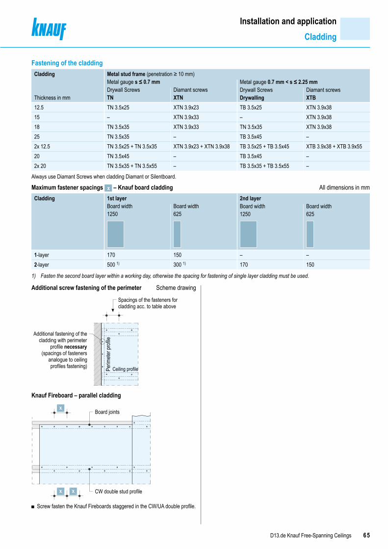
65D13.de Knauf Free-Spanning Ceilings
Installation and applicationCladding
Fastening of the cladding Cladding Metal stud frame (penetration ≥ 10 mm)
Metal gauge s ≤ 0.7 mm Metal gauge 0.7 mm < s ≤ 2.25 mm
Thickness in mmDrywall ScrewsTN
Diamant screwsXTN
Drywall ScrewsDrywalling
Diamant screwsXTB
12.5 TN 3.5x25 XTN 3.9x23 TB 3.5x25 XTN 3.9x3815 – XTN 3.9x33 – XTN 3.9x3818 TN 3.5x35 XTN 3.9x33 TN 3.5x35 XTN 3.9x3825 TN 3.5x35 – TB 3.5x45 –2x 12.5 TN 3.5x25 + TN 3.5x35 XTN 3.9x23 + XTN 3.9x38 TB 3.5x25 + TB 3.5x45 XTB 3.9x38 + XTB 3.9x5520 TN 3.5x45 – TB 3.5x45 –2x 20 TN 3.5x35 + TN 3.5x55 – TB 3.5x35 + TB 3.5x55 –
Always use Diamant Screws when cladding Diamant or Silentboard.
Maximum fastener spacings x – Knauf board cladding All dimensions in mmCladding 1st layer 2nd layer
Board width1250
Board width625
Board width1250
Board width625
1-layer 170 150 – –2-layer 500 1) 300 1) 170 150
1) Fasten the second board layer within a working day, otherwise the spacing for fastening of single layer cladding must be used.
Additional screw fastening of the perimeter Scheme drawing
Spacings of the fasteners forcladding acc. to table above
Ceiling profilePerim
eter p
rofile
Additional fastening of thecladding with perimeter
profile necessary (spacings of fasteners
analogue to ceilingprofiles fastening)
S V h b UW P filKnauf Fireboard – parallel cladding
Board joints
CW double stud profile
x
x x
■ Screw fasten the Knauf Fireboards staggered in the CW/UA double profile.

66 D13.de Knauf Free-Spanning Ceilings
Installation and applicationJointing
JointingJointing of the boards in the required quality level Q1 to Q4 in accordance with Code of Practice no. 2 “Verspachtelung von Gipsplatten, Oberflächengüten”1).With Fireboard, a skim coating of the entire surface with Knauf Fireboard Spachtel filler is additionally required before application of direct coatings or linings.Suitable jointing materials
■ Uniflott: Hand filling without joint tape strips in the long joint edges ■ Uniflott impregnated: Hand filling of impregnated boards without joint tape in the long edge joints, water-repellent, matching green colour
■ Fugenfüller Leicht: Hand filling with joint tape, preferably with Knauf Fugendeckstreifen Kurt joint tape
■ Fireboard Spachtel filler: Hand filling of Fireboard with Fibre Glass Joint Tape
Suitable finish filling compounds ■ Q2, application by hand: Uniflott, Uniflott imprägniert, Readygips, Fill & Finish or SuperFinish
■ Q3/Q4, application by hand: Readygips, SuperFinish, Fill & Finish or ProSpray Light
■ Q3/Q4, machine application: Readygips, ProSpray Light ■ Fireboard Spachtel filler for full surface skimming of Fireboard
Filling of the gypsum boards ■ For multi-layer cladding, fill the lower layers with filler; fill the joints of the visible layer. Filling the joints of covered cladding layers with multi-layer cladding is necessary to provide technical fire resistance and sound insulation properties as well as the structural properties!
■ Recommendation: Front edge and cut edge joints as well as mixed joints (e.g. HRAK + cut edge) of the visible cladding layers filled using Uniflott will require the application of Fugendeckstreifen Kurt joint tape as well.
■ Fill in visible screw heads. ■ Lightly sand visible surfaces after drying of the filler material, if required.
Joint filling of the connection joints ■ Apply Trenn-Fix or Fugendeckstreifen Kurt joint tape when filling joints to adjacent drywall constructions, taking into consideration the conditions and requirements for crack safety.
■ Observe code of practice no. 3 “Gipsplattenkonstruktionen - Fugen und Anschlüsse” (German only) 1).
■ Apply Trenn-Fix when filling joints to adjacent solid construction components.
Application temperature / climate ■ Filling and covering of joints should only take place when no more longitudinal changes can be expected, i.e. expansion or contraction due to humidity or temperature changes.
■ Do not apply filling at room or substrate temperatures below approx. +10 °C.
■ In case of mastic asphalt screed, cementitious screed and self-levelling screed, fill in board joints after screed has been applied.
■ Observe code of practice no. 1 “Baustellenbedingungen” 1).
Quality levels
Joint implementation Long edges half-rounded tapered edge / half-rounded edge
Joint implementationFront edge bevelled cut edge
Descriptionworking steps
Q1 ■ Fill joints with Uniflott or Uniflott imprägniert ■ Fill the visible parts of the fastener
Q2 ■ Preliminary jointing in acc. with quality level Q1 ■ Finish (finish compound) until a smooth transition to the board surface with Uniflott, Uniflott imprägniert, Readygips, Fill & Finish or SuperFinish
No application marks or ridges may remain visible. Sand off the areas concerned if necessary.
Q3 ■ Jointing in acc. with quality level Q2 ■ Wide jointing of the joints as well as clean and ac-curate removal of the remaining board liner filling the pores, e.g. with Readygips, Knauf SuperFinish, Fill & Finish or ProSpray Light
If necessary, i.e. physical ridges and grooves if present are not acceptable and must be sanded.
Q4
■ Jointing in acc. with quality level Q2 ■ Complete surface covering of skim coat with a layer thickness of at least 1 mm, e.g. with Readygips, ProSpray Light.
1) “Building Site Conditions” issued by the Industriegruppe Gipsplatten im Bundesverband der Gipsindustrie e.V.
67D13.de Knauf Free-Spanning Ceilings
Installation and applicationCoatings and linings
Surface treatmentFor direct application of a coarse texture wallpaper, the surface must at least have quality level Q2. For direct application of a textured paint coat, the surface must at least have quality level Q3.With Fireboard, the surface must be completely filled in both cases, e.g. with Fireboard-Spachtel filler.PretreatmentBefore further coatings or linings (wallpaper) are applied, the filled surface must be free of dust and the surface of the gypsum boards should always be primed, acc. to code of practice no. 6 of the BVG “Vorbehandlung von Trockenbauflächen aus Gipsplatten zur weitergehenden Oberflächenbeschichtung bzw. –bekleidung” 1) (German only). Ensure that the primer and the coating / paint / lining are compatible. In order to compensate for the differences in absorption of surfaces, coatings of primer such as Knauf Tiefengrund primer is suitable.Where a wallpaper lining is used, a primer that facilitates easier removal of wallpaper for redecoration is recommended.
Suitable coatings and linings The following coatings / linings can be applied to Knauf boards:
■ Wallpapers ▪ Paper, fleece, textile and synthetic wallpapers:
Use only adhesives made of methyl cellulose according to Code of Practice no. 16 “Technische Richtlinien für Tapezier- und Klebearbeiten” released by the Bundesausschuss Farbe und Sachwertschutz.
■ Plasters ▪ Top coats (e.g. Noblo, Diamant Spritzputz spray plaster, Rotkalk Filz) ▪ Full surface plaster (e.g. Knauf Readygips, Multi-Finish).
Application of plaster layers only in conjunction with Fugendeckstreifen Kurt joint tape.
■ Decorative coats ▪ Dispersion paint (e.g. Intol E.L.F., Malerweiss E.L.F.), ▪ Multicoloured (rainbow) emulsion ▪ Silicate-based emulsion paints with suitable primer.
Unsuitable coatings and linings ■ Alkaline coats such as lime, water glass paints and silicate-based paints.
Notes
Gypsum board surfaces that have constantly been exposed to light without any protection can cause yellowing after coating. Therefore, a trial coat is recommended that will extend across several boards including all joints. Yellowing can, however, be successfully avoided only by using a special primer, such as Knauf Sperrgrund barrier coating.Other coatings or layers and vapour barriers up to about 0.5 mm thickness as well as claddings (with the exception of sheet steel), do not have any influence on the technical fire resistance classification of Knauf Free-Spanning Ceiling systems.After wallpapering or after application of plasters, quick drying must be ensured through adequate airing.

68 D13.de Knauf Free-Spanning Ceilings
Material requirementKnauf Free-Spanning Ceilings D131.de
Material requirement per m² ceiling without allowance for loss and wasteDescription Unit Amount as average value
1 2 3 4 5
Connection to wall with furring channel CWKnauf UW runner m 0.8 0.8 0.8 0.8 0.8Suitable fastener material, e.g.
Knauf Multi-purpose screw 2x FN with metal stud partition pcs. 2.7 2.7 2.7 2.7 2.7Alternative Knauf Deckennagel ceiling steel dowel with reinforced concrete pcs. 2.8 2.8 2.8 2.8 2.8Knauf CW profile m 0.2 0.2 0.2 0.2 0.2Suitable fastener material, e.g.
Knauf Multi-purpose screw FN with metal stud partition pcs. as req. as req. as req. as req. as req.Alternative Knauf Deckennagel ceiling steel dowel with reinforced concrete pcs. as req. as req. as req. as req. as req.Covering strips 50 mm wide: Knauf Piano fire-resistant board or Diamant; 12.5 mm m2 – – – – 0.05Connection to wall with furring channel UAKnauf UW runner m 0.8 0.8 0.8 0.8 0.8Suitable anchors, e.g. Knauf Deckennagel ceiling steel dowels with reinforced concrete pcs. 1.4 1.4 1.4 1.4 1.4
Knauf Connection Angle with UA 50/75 pcs. 1.5 1.9 1.5 1.2 1.5Connection bolt M8, pcs. 3.0 3.8 3.0 2.4 3.0Suitable anchors, e.g. Knauf Deckennagel ceiling steel dowels with reinforced concrete pcs. 3.0 3.8 3.0 2.4 3.0
Alternative Knauf Cubo connection brackets with UA 100/125/150 pcs. 1.5 1.9 1.5 1.4 1.5Connection bolt M8, pcs. 3.0 3.8 3.0 2.4 3.0Suitable anchors, e.g. Knauf Deckennagel ceiling steel dowels with reinforced concrete pcs. 6.0 7.6 6.0 4.8 6.0
Knauf UA profile m 0.2 0.2 0.2 0.2 0.2Suitable anchors, e.g. Knauf Deckennagel ceiling steel dowels with reinforced concrete pcs. as req. as req. as req. as req. as req.
Knauf Connection Angle with UA 50/75 pcs. 0.2 0.2 0.2 0.2 0.2Connection bolt M8, pcs. 0.3 0.3 0.3 0.3 0.3Suitable anchors, e.g. Knauf Deckennagel ceiling steel dowels with reinforced concrete pcs. 0.3 0.3 0.3 0.3 0.3
Alternative Knauf Cubo Connection Brackets with UA 100/125/150 pcs. 0.2 0.2 0.2 0.2 0.2Connection bolt M8, pcs. 0.3 0.3 0.3 0.3 0.3Suitable anchors, e.g. Knauf Deckennagel ceiling steel dowels with reinforced concrete pcs. 0.3 0.3 0.3 0.3 0.3
GridKnauf CW single profile m 1.9 – – – –Connection of Knauf CW profile with lateral Knauf UW perimeter runner: e.g. steel rivet pcs. 1.7 – – – –
Alternative Knauf UA single profile m 1.9 – – – –Knauf CW double profile m – 4.8 3.8 3.0 3.8Knauf Metal Screw LN 3.5x11 mm (Knauf CW profiles screwed at flange) pcs. – 4.0 3.0 2.4 3.0Connection of Knauf CW profile with Knauf UW perimeter runner: e.g. 2x metal rivets pcs. – 4.0 3.2 2.6 –
Alternative Knauf UA double profile m – 4.8 3.8 3.0 3.8Bolts M8 (Knauf UA profiles screwed at flange) pcs. – 4.0 3.0 2.4 3.0
Covering strips 120 mm wide: Solid Board; 25 mm m2 – – – 0.2 –Covering strips 100 mm wide: Knauf Piano fire-resistant board or Diamant; 12.5 mm m2 – – – – 0.2Fastening of covering strips: Knauf drywall screws, see pages 58, 59 pcs. – – – 8 13Insulation layer e.g. Knauf Insulation (observe fire resistance and/or sound insulation) m2 as req. 1.0 1.0 1.0 1.0
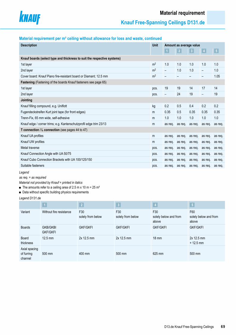
69D13.de Knauf Free-Spanning Ceilings
Material requirementKnauf Free-Spanning Ceilings D131.de
Material requirement per m² ceiling without allowance for loss and waste, continuedDescription Unit Amount as average value
1 2 3 4 5
Knauf boards (select type and thickness to suit the respective systems)1st layer m2 1.0 1.0 1.0 1.0 1.02nd layer m2 – 1.0 1.0 – 1.0Cover board: Knauf Piano fire-resistant board or Diamant; 12.5 mm m2 – – – – 1.05Fastening (Fastening of the boards Knauf fasteners see page 65)1st layer pcs. 19 19 14 17 142nd layer pcs. – 24 19 – 19JointingKnauf filling compound, e.g. Uniflott kg 0.2 0.5 0.4 0.2 0.2Fugendeckstreifen Kurt joint tape (for front edges) m 0.35 0.5 0.35 0.35 0.35Trenn-Fix, 65 mm wide, self-adhesive m 1.0 1.0 1.0 1.0 1.0Knauf edge / corner trims; e.g. Kantenschutzprofil edge trim 23/13 m as req. as req. as req. as req. as req.T connection / L connection (see pages 44 to 47)Knauf UA profiles m as req. as req. as req. as req. as req.Knauf UW profiles m as req. as req. as req. as req. as req.Metal traverse pcs. as req. as req. as req. as req. as req.Knauf Connection Angle with UA 50/75 pcs. as req. as req. as req. as req. as req.Knauf Cubo Connection Brackets with UA 100/125/150 pcs. as req. as req. as req. as req. as req.Suitable fasteners pcs. as req. as req. as req. as req. as req.
Legendas req. = as requiredMaterial not provided by Knauf = printed in italics
■ The amounts refer to a ceiling area of 2.5 m x 10 m = 25 m² ■ Data without specific building physics requirements
Legend D131.de
1 2 3 4 5
Variant Without fire resistance F30 solely from below
F30 solely from below
F30 solely below and from above
F60 solely below and from above
Boards GKB/GKBIGKF/GKFI
GKF/GKFI GKF/GKFI GKF/GKFI GKF/GKFI
Board thickness
12.5 mm 2x 12.5 mm 2x 12.5 mm 18 mm 2x 12.5 mm+ 12.5 mm
Axial spacing of furring channel
500 mm 400 mm 500 mm 625 mm 500 mm

70 D13.de Knauf Free-Spanning Ceilings
Material requirementKnauf Free-Spanning Ceilings K219.de
Material requirement per m² ceiling without allowance for loss and wasteDescription Unit Amount as average value
6 7
Connection to wall with furring channel CWKnauf UW runner m 0.8 0.8Suitable fastener material, e.g.
Knauf Multi-purpose Screw 2x FN with metal stud partition pcs. 2.7 5.3Alternative Knauf Deckennagel ceiling steel dowel with reinforced concrete pcs. 2.8 3.3Knauf CW profile m 0.2 0.2Suitable fastener material, e.g.
Knauf Multi-purpose Screw FN with metal stud partition pcs. as req. as req.Alternative Knauf Deckennagel ceiling steel dowel with reinforced concrete pcs. as req. as req.Connection to wall with furring channel UAKnauf UW runner m 0.8 0.8Suitable anchors, e.g. Knauf Deckennagel ceiling steel dowels with reinforced concrete pcs. 1.4 1.4
Knauf Connection Angle with UA 50/75 pcs. 1.2 1.2Connection bolt M8, pcs. 2.4 2.4Suitable anchors, e.g. Knauf Deckennagel ceiling steel dowels with reinforced concrete pcs. 2.4 2.4
Alternative Knauf Cubo Connection Brackets with UA 100/125/150 pcs. 1.2 1.2Connection bolt M8, pcs. 2.4 2.4Suitable anchors, e.g. Knauf Deckennagel ceiling steel dowels with reinforced concrete pcs. 4.8 4.8
Knauf UA profile m 0.2 0.2Suitable anchors, e.g. Knauf Deckennagel ceiling steel dowels with reinforced concrete pcs. as req. as req.
Knauf Connection Angle with UA 50/75 pcs. 0.2 0.2Connection bolt M8, pcs. 0.3 0.3Suitable anchors, e.g. Knauf Deckennagel ceiling steel dowels with reinforced concrete pcs. 0.3 0.3
Alternative Knauf Cubo connection brackets with UA 100/125/150 pcs. 0.2 0.2Connection bolt M8, pcs. 0.3 0.3Suitable anchors, e.g. Knauf Deckennagel ceiling steel dowels with reinforced concrete pcs. 0.3 0.3
GridKnauf CW double profile m 3.0 3.0Knauf Metal Screw LN 3.5x11 mm (Knauf CW profiles screwed at flange) pcs. 3.0 3.0
Alternative Knauf UA double profile m 3.0 3.0Bolts M8 (Knauf UA profiles screwed at flange) pcs. 3.0 3.0
Covering strips 120 mm wide: Fireboard 12.5 mm m2 – 0.4Fastening cover strips - Knauf Schnellbauschrauben drywall screws TN 3.5x25 pcs. – 15Insulation layer e.g. Knauf Insulation (observe fire resistance and/or sound insulation) m2 as req. 1.0
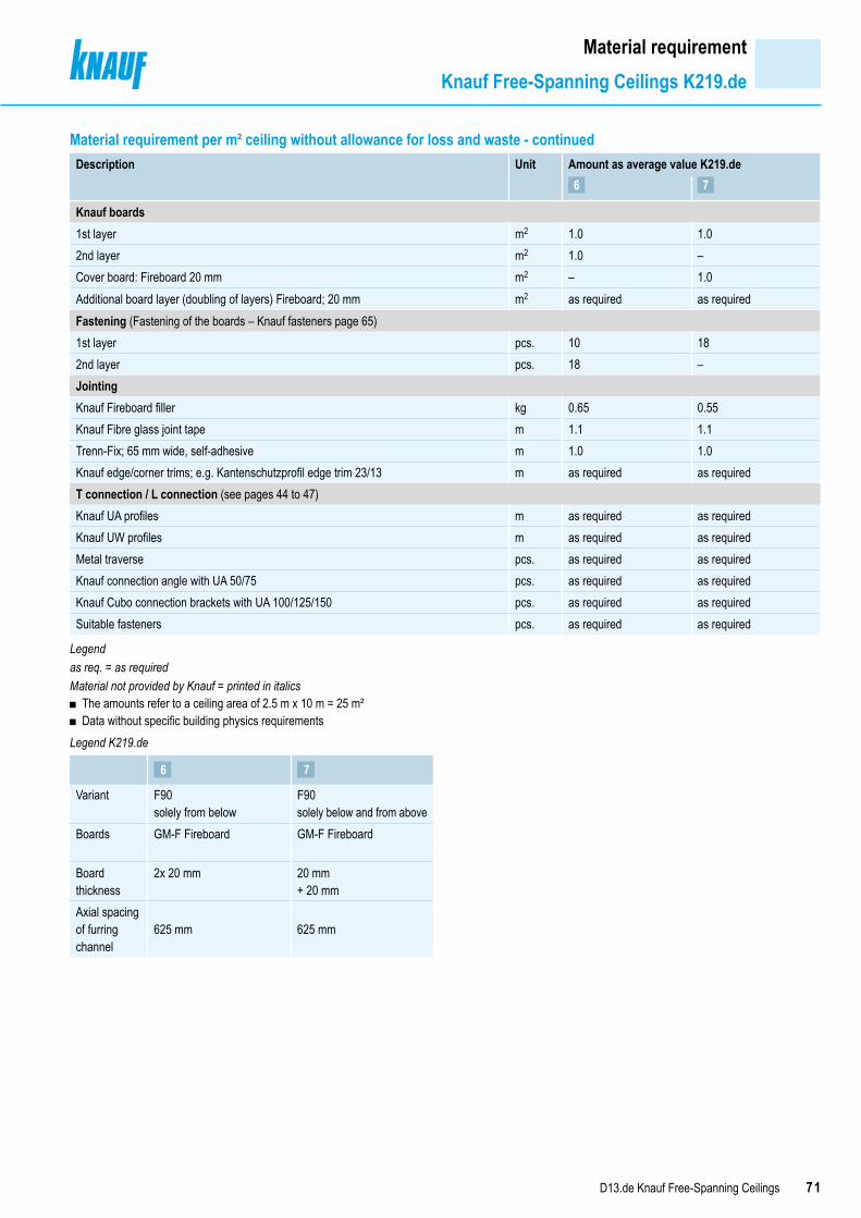
71D13.de Knauf Free-Spanning Ceilings
Material requirementKnauf Free-Spanning Ceilings K219.de
Material requirement per m² ceiling without allowance for loss and waste - continuedDescription Unit Amount as average value K219.de
6 7
Knauf boards1st layer m2 1.0 1.02nd layer m2 1.0 –Cover board: Fireboard 20 mm m2 – 1.0Additional board layer (doubling of layers) Fireboard; 20 mm m2 as required as requiredFastening (Fastening of the boards – Knauf fasteners page 65)1st layer pcs. 10 182nd layer pcs. 18 –JointingKnauf Fireboard filler kg 0.65 0.55Knauf Fibre glass joint tape m 1.1 1.1Trenn-Fix; 65 mm wide, self-adhesive m 1.0 1.0Knauf edge/corner trims; e.g. Kantenschutzprofil edge trim 23/13 m as required as requiredT connection / L connection (see pages 44 to 47)Knauf UA profiles m as required as requiredKnauf UW profiles m as required as requiredMetal traverse pcs. as required as requiredKnauf connection angle with UA 50/75 pcs. as required as requiredKnauf Cubo connection brackets with UA 100/125/150 pcs. as required as requiredSuitable fasteners pcs. as required as required
Legendas req. = as requiredMaterial not provided by Knauf = printed in italics
■ The amounts refer to a ceiling area of 2.5 m x 10 m = 25 m² ■ Data without specific building physics requirements
Legend K219.de
6 7
Variant F90 solely from below
F90 solely below and from above
Boards GM-F Fireboard GM-F Fireboard
Board thickness
2x 20 mm 20 mm+ 20 mm
Axial spacing of furring channel
625 mm 625 mm

All technical changes reserved. Only the current printed instructions are valid. The stated information represents current state-of-the-art Knauf technology. The entire state of approved engineering rules, appropriate standards, guidelines, and rules of crafts-manship are not included herewith. These and all application instructions have to be adhered to separately by the installer. Our warranty is expressly limited to our products in flawless condition. All application quantities and delivery amounts are based on empirical data that are not easily transferable to other deviating areas.All rights reserved. All amendments, reprints and photocopies, including those of excerpts, require our expressed permission.
The stated constructional and structural design specifications and characteristics of building physics of Knauf systems can only be ensured with the exclusive use of Knauf system components, or other products expressly recommended by Knauf.
Knauf Gips KG Am Bahnhof 7, 97346 Iphofen, GermanyKnauf DirectTechnical Advisory Service:
www.knauf.de
The iPad App Knauf Infothek now provides all the current information and documents from Knauf Gips KG at any time and in every location in a clear and comfortable way.Knauf Infothek
Information on sustainabilityKnauf Free-Spanning Ceilings
Information on sustainability of Knauf Free-Spanning Ceiling systemsBuilding assessment systems ensure the sustainable quality of buildings and constructional structures by a detailed assessment of ecological, economic, social, functional and technical aspects.In Germany, the following certification systems are of particular relevance:
■ DGNB System German seal of approval for environmentally sustainable building from the DGNB (German association for environmentally sustainable building)
■ BNB (Bewertungssystem Nachhaltiges Bauen - Quality rating system for environmentally sustainable building)
■ LEED (Leadership in Energy and Environmental Design).
Knauf products and free-spanning ceiling systems can positively influence many of these criteria.
DGNB/BNBEcological quality
■ Criterion: Risks for the local environment The relevant environmental data are contained in the EPD for gypsum products
Economic quality ■ Criterion: Building related life-cycle costs Cost-effective Knauf Drywalling
Sociocultural and functional quality ■ Criterion: Suitability for conversion Flexible Knauf Drywalling
Technical quality ■ Criterion: Fire resistance Comprehensive fire resistance know-how
■ Criterion: Sound insulation Exceeding the demands of the standard with Knauf sound protection
■ Criteria: Ease of dismantling and recycling Knauf Drywalling is fully compliant
LEEDMaterials and resources
■ Credit: Recycled Content Recycled content in Knauf boards, e.g. FGD gypsum
■ Credit: Regional Materials Short transport routes provided by the extensive network of Knauf manufacturing facilities
Detailed information on request and online at:www.knauf-blue.de
D13.de/eng/07.17/0/Dbl


![M100 Shapes LED Recessed [L10/L1R] selux€¦ · After Drywall Flange Mounting (SF3) 1. Drywall/Drywall screw (Ref.) 2. Drywall/Drywall (Ref.) 3. 1/6” Plaster skimcoat (Ref.) 4](https://img.pdfslide.us/doc/110x75/5f54633924da634fd0733121/m100-shapes-led-recessed-l10l1r-selux-after-drywall-flange-mounting-sf3-1.jpg)