Embed Size (px)
Citation preview

SFLC STANDARD SPECIFICATION 8634
Jan 2009 1 8634
DRYDOCKING
1. SCOPE
1.1 Intent. This Standard Specification describes the requirements for the Contractor to drydock and undock U.S. Coast Guard vessels.
1.2 Appendices. The following appendices apply to this standard specification.
PROCESS STANDARD APPENDIX
Requirement for Calculations A
Requirements for Facility Inspection B
Requirements for Docking and Lifting Cradles C
1.3 Acronyms and term definitions. Below are definitions of various acronyms and terms that are used in this standard or may be encountered in work item specifications.
• “Drydock”: When used generically in this specification, this term refers to all means of removing a vessel from the water, including Graving Docks, Floating Drydocks, Marine Railways, Vertical Shiplifts (e.g. Syncrolift™) and crane (e.g. Travel Lift™).
• “GM”: Transverse Metacentric height (stability index). • “Haul out”: A haul out is defined as lifting or hoisting of a vessel, where arrival condition is
either afloat or in a cradle on a trailer, using a heavy lift rigging configuration with a crane, derrick, or gantry type crane (e.g. Travel Lift).
• “Facility”: Refers to a specific drydock operated by Contractor with unique identity (designator, model number, etc.)
• “Fleet/Fleeting”: The action of refloating and shifting of a vessel to an alternate docking position to facilitate 100% preservation of the vessel's underwater body, or other necessary work.
• “KG”: Vertical Center of Gravity (VCG) above the baseline (keel). • “KM”: Metacentric height above the baseline (keel). • “LOA”: Length over all. • “Soft cap”: Forms the top of the keel or side/bilge block, usually; has lower permissible
compressive stress and proportional limit than other materials used in block construction.
SFLC STANDARD SPECIFICATION 8634
Jan 2009 2 8634
2. REFERENCES
COAST GUARD DRAWINGS
Coast Guard Drawing 87 WPB 085-010, Rev D, Docking Plan
Coast Guard Drawing 87 WPB 085-012, Rev -, Lifting Cradle
Coast Guard Drawing 110 WPB 085-002, Rev -, Docking Plan
Coast Guard Drawing 110 WPB 085-010, Rev B, Docking Plan, Docking/Lifting Cradle (‘A’, ‘B’, & ‘C’ Classes)
COAST GUARD PUBLICATIONS
Surface Forces Logistics Center Standard Specification 0000 (SFLC Std Spec 0000), Jan 2009, General Requirements
Surface Forces Logistics Center Standard Specification (SFLC Std Spec 0740), Jan 2009, Welding and Allied Processes
OTHER REFERENCES
American Bureau of Shipping (ABS), Rules for Survey after Construction, 2009, Part 7, Chapter 10, Steel Floating Drydocks
Rules and Regulations for the Construction and Classification of Floating Docks, Lloyd’s Register 2003
Code for Lift Appliances in a Marine Environment, Lloyd’s Register 2008
Code of Federal Regulations (CFR) Title 29, Part 1917.50, July 2008, Marine Terminals, July 2008
Code of Federal Regulations (CFR) Title 29, Part 1919, July 2008, Gear Certification
MIL-STD-1625, Aug 2009, Safety Certification Program for Drydocking Facilities and Shipbuilding Ways for U.S. Navy Ships
The Society for Protective Coatings (SSPC)/NACE International (NACE) Joint Surface Preparation Standard SSPC-SP 12/NACE No.5, 2002, Surface Preparation and Cleaning of Metals by Waterjetting Prior to Recoating

SFLC STANDARD SPECIFICATION 8634
Jan 2009 3 8634
3. REQUIREMENTS
3.1 General. The Contractor shall maintain facility certification and subsequently meet the requirements to drydock/undock a designated Coast Guard vessel as specified in this standard and in accordance with requirements specified in SFLC Std Spec 0000.
3.2 Requirement for certification. The Contractor’s drydock shall first be certified by a Coast Guard-approved method as specified in this standard.
NOTE
The certification methods, calculations and related items listed throughout this specification ensure that the contracted drydock has sufficient lifting capacity and structural strength for safely handling a Coast Guard vessel within the trim
and stability requirements for drydocking. This certification also serves as verification that the Contractor shall maintain compliance with the industrial standards for safety.
3.2.1 Submittal of drydock certification. The Contractor shall submit documentation of their facility’s drydock certification to the KO for approval. Be aware that Coast Guard approval shall be based on review and acceptance of the certification by the COTR.
3.2.2 Drydock certification. The Contractor shall be aware that the criteria for their drydock capability shall be based on inspection, see Appendix B for details of inspection criteria. If the Contractor possesses more than one type of drydock, each dock shall be certified individually.
3.2.2.1 Block/Cradle foundation certification. If the final docking location of the vessel on blocks/cradle is not on the dock floor of a certified graving dock, floating drydock, marine railway, or vertical lift, the block/cradle foundation site shall be certified separately by a Professional Engineer (see 3.2.3.2 (Clarification for drydock certification methods)).

SFLC STANDARD SPECIFICATION 8634
Jan 2009 4 8634
3.2.3 Drydock certification method. Proof of structural and operational integrity of a Contractor’s drydock facility and certification shall be achieved by one of the following methods:
TYPE OF DRYDOCK FACILITY APPLICABILITY CERTI-
FICATION TYPE
ACCEPTABLE STANDARD/
DOCUMENTATION FLOATING GRAVING MARINE RAILWAY
VERTICAL LIFT
CRANE/ TRAVEL
LIFT
DOCKING/ LIFTING CRADLE
NAVSEA MIL-STD-1625 (Sections 1.2.4 and 4.10.5 do not apply)
● ● ● ● ●
Professional Engineer
Independent Professional Engineer inspection survey of the drydock condition that is signed and sealed
● ● ● ● ● ●
Lloyd’s Register
Rules and Regulations for the Construction and Classification of Floating Docks. Code for Lifting Gear in a Marine Environment; Chapter 3, 4, 6, 9 and 10
● ● ● ●
American Bureau of Shipping
(ABS)
Rules for Survey After Construction ●
OSHA 29 CFR Part 1917 and Part 1919 ● ●

SFLC STANDARD SPECIFICATION 8634
Jan 2009 5 8634
3.2.3.1 Certification inclusions. Regardless of the type of certification provided, the Contractor shall submit to the KO the following information regarding the docking facility:
• Fire alarm locations. • Emergency power plan. • Emergency ballast/dewatering pumping plan showing pump locations, applicable to floating
drydocks and graving docks only.
3.2.3.2 Clarification for drydock certification methods. The Contractor shall be aware that certification methods listed above are explained as follows:
3.2.3.2.1 Inspection survey. The inspection survey checklists for all types of drydocks and block/cradle foundations are defined in Appendix B (Requirements for Facility Inspection). The format of the inspection checklists, provided in Appendix B, shall be used in validation of certification by an independent Professional Engineer.
3.2.3.2.2 Drydock certification period. Coast Guard approval of the submitted certification shall remain in affect as long as the certification is current and contractor is in compliance with the certifying agency’s requirements. In the case of an independent Professional Engineer’s inspection survey, the period of certification is defined in Appendix B.
3.2.3.2.3 Validation of operational test. For a valid operational test, the lifting equipment shall be tested to a minimum of 125% of the weight of the vessel to be drydocked. The Contractor shall provide documentation of current calibration for the load cell that is used in recording the test weight.
3.2.3.2.4 Cradle construction and test. The Contractor shall be aware that requirements for the construction and operational testing of docking and lifting cradles are defined in Appendix C (Requirements for Docking and Lifting Cradles).
3.2.3.2.5 Cradle inspection. In the presence of the certifying agency, the Contractor shall perform NDI of the cradle/spreader bar weld joints designated by the certifying agency in accordance with SFLC Std Spec 0740, Appendix C for each certification inspection cycle (see B2.3.1 (Cycle for cradle certification)). The certifying agent shall provide a signed/sealed written test report for the completed NDI test to the Contractor for submittal to the KO.
3.2.3.2.6 Modification of a certified drydock. The Contractor shall report any changes, modifications or major repairs made to their drydock structure/facility to the certification agency as well as to the Coast Guard KO. The certification shall be revised to document the structural/facility modification and resubmitted to KO for approval. The certification revision shall be approved prior to docking any USCG asset.
3.3 Docking personnel. The Contractor shall provide qualified docking personnel and a qualified Dockmaster.
3.3.1 Dockmaster. The Contractor shall provide written certification for the Dockmaster and include a resume stating training and experience that meets one of the following criteria:
• Has served as a Dockmaster at the type of facility for which the individual is qualified during at least 10 docking/undocking evolutions, of which one has been accomplished within the previous 6 months.
• Has served under a Dockmaster, in an apprentice or assistant role during at least 20

SFLC STANDARD SPECIFICATION 8634
Jan 2009 6 8634
docking/undocking evolutions, of which 10 have been performed at the type of facility for which the individual is qualified with one docking/undocking evolutions conducted within the previous 6 months.
• Has served under a Dockmaster in an apprentice or assistant role during at least 10 docking/undocking evolutions and has served as a Dockmaster at the type of facility for which the individual is qualified during at least 5 docking/undocking evolutions, of which one has been accomplished within the previous 6 months.
3.3.2 Manning personnel. The Contractor personnel stationed for the drydocking evolution shall be experienced in drydocking operations and equipped with appropriate tools and communication devices throughout the dock/undock evolution.
3.4 Drydocking events.
3.4.1 Pre-award events.
3.4.1.1 Documentation Submittal. If certification is not currently on file with Coast Guard, the Contractor shall submit their drydock certification (see 3.2.1 (Submittal of drydock certification)) at the time of pre-award to the KO for approval. The contractor shall also submit written certification and resume of Dockmaster (see 3.3 (Docking personnel)).
3.4.1.2 Pre-award calculations. The Contractor shall provide to the KO a set of pre-award calculations, as described in Appendix A.
3.4.1.2.1 Vessel information. The Contractor shall be provided with docking plan information/drawings, hydrostatic information and specific vessel Principle Characteristics in the work package from the KO. For additional information necessary to perform drydock calculations submit a request to the KO.
3.4.1.2.2 Validation of dock capacity. For validation of the Contractor’s drydock maximum rated capacity as stated in the submitted certification. In relation to the specific vessel’s displacement that is to be drydocked, the Contractor’s drydock capacity shall be a minimum of 125% of the weight of the vessel as provided (see 3.4.1.2.1 (Vessel information)).
3.4.1.2.2.1 Evaluation of dock capacity. In a case where the drydock maximum rated capacity does not meet the validation requirement (see 3.4.1.2.2 (Validation of dock capacity)), the Contractor’s pre-award calculations shall include liquid and dead loading instructions, with resultant VCG, TCG, LCG and GM factors, for the specific vessel. The Contractor shall demonstrate the drydocking can safely be accomplished. This shall be considered a unique Contractor requirement to dock the vessel and shall be reviewed accordingly.
3.4.1.2.2.2 Review of Contractor’s requirement. The Contractor shall provide the KO their unique requirement for the vessel’s loading at pre-award for review by the COTR. The KO shall provide the Contractor the results of the review prior to contract award.

SFLC STANDARD SPECIFICATION 8634
Jan 2009 7 8634
3.4.2 Pre-Docking events.
3.4.2.1 Vessel arrival load conditions. The Contractor shall be provided with the vessel’s estimated arrival loading conditions by the COTR no later than seven days before the docking day. If the vessel’s estimated trim or list requires a reduction, the Contractor shall coordinate with the COTR to accomplish the following:
3.4.2.1.1 Trim considerations. The Contractor shall work with the COTR and vessel’s CO to obtain minimal trim. When it is necessary or desirable to dock a vessel with appreciable trim, both the point load on the knuckle block and the maximum unit stress at the after end of the knuckle block must remain within permissible limits of the timber, as shown in Appendix A.
3.4.2.1.2 List considerations. The Contractor shall work with the COTR and vessel’s CO to ensure that all list (angle of list = 0 degrees), as practicable, shall be eliminated before attempting to drydock.
NOTE
If examination of the vessel by the Contractor’s Dockmaster is not possible before docking, the COTR/CO will inform the Contractor of the amount of list, and its probable cause. This information shall be furnished sufficiently in advance of
the time of drydocking to permit safe docking arrangements to be made without delay.
3.4.2.2 Block construction. The Contractor shall arrange keel and bilge blocks, as shown on the USCG docking plan for the vessel class, ensuring the following:
• The dimensional tolerances for the vessel's docking plan shall be the following: • The height of the vessel's keel and bilge side/blocks are within ¼”. • The distances in the longitudinal direction are within 1”. • The distances of the half breadths (transverse) for side/bilge blocks are within ½”. • The soft caps shall be made of Douglas Fir or Pine, on both keel and side/bilge blocks with a
thickness minimum of 2” and a maximum of 6”. The keel line soft caps shall not be thicker than those on the bilge blocks. Reused soft caps shall be free from any permanent deformations, i.e. crushing, cracking or other material defects.
• The line of normal force for all blocking shall pass through the middle one-third of the block base as shown in Figure 1 (Bilge Block Construction).
• The docking blocks shall be made of homogeneous materials. Every block in the keel line shall be fabricated of the same materials. Every block used for bilge/side support shall all be fabricated of uniform structure and materials. The bilge blocks shall not be fabricated with stiffer construction material than the keel blocks. Block material below the soft cap, shall be constructed of one of the following materials: concrete, hard wood or steel.
• For blocking that will be submerged, all blocks shall be securely dogged to prevent wood from floating out of the dock during the docking/undocking evolution
• Bilge blocks higher than six feet, as measured from the bottom of the block to the highest point of the soft cap, shall be tied together in pairs by means of cribbing or bracing. If the side blocks are hauled into position during the docking evolution while tied together, then they shall be hauled simultaneously. When bracing two blocks together, the minimum acceptable bracing material shall be four (2”x6”) wooden planks in a cross-braced pattern and lag bolted in place, shown in Figure 2 (Braced Bilge Blocks).
SFLC STANDARD SPECIFICATION 8634
Jan 2009 8 8634
• Keel blocks higher than six feet shall be cribbed together in the both forward and after one third of the keel block line. The cribbing shall be a minimum of 12-inch thick when used with timber blocks.
• Blocks constructed for vessel dockings/haul outs, shall be placed on a permanent solid foundation such as concrete, concrete aggregate, dock floors, or cradle fixtures. Cradle fixtures used for vessel haul outs shall be placed on a permanent solid foundation. No block or cradle shall rest on loose soil, gravel, sand or other non-permanent foundation. (See 3.2.2.1 (Block/Cradle foundation certification).)
CAUTION!
In cases where cradle fixtures are combined with additional blocks, both shall be placed on a permanent solid foundation of uniform composition.
NOTE
The position of the vessel on the blocks, as found in the docking plan drawing, will be specified in the work item provided in the work package. Sequential positioning (1, 2, etc) allows for paint schedules to cover the hull plate over multiple
docking cycles.
3.4.2.3 Access to hull fittings. While constructing the block build, according to the docking plan provided in the work package, the Contractor shall ensure that no obstructions exist between the drydock surface and hull openings or fittings. Also, ensuring horizontal and vertical clearance to remove and replace appendages, including but not limited to rudders, shafts, fin stabilizers, transducers, sonar domes, and retractable bow thrusters, as applicable. This clearance shall be considered whether or not removals are specified in the work package.
3.4.2.4 Vessel arrival. The Contractor shall dock the vessel within 72 hours after the vessel has arrived at the Contractor's facility. Except in the case where a pre-docking shaft alignment check shall be performed. When a pre-docking shaft alignment is performed, ensure that the vessel is drydocked within 120 hours after arrival.
3.4.2.5 Seventy-two hours before docking. The Contractor shall submit to the KO for review by the COTR the docking calculations, as required in Appendix A. As applicable, the Contractor shall also submit an alternate docking block arrangement, which consists of any changes from the CG docking plan provided in the work package. A Contractor’s alternate docking plan/block arrangement shall be approved by the KO prior to docking a CG vessel.
3.4.2.6 Twenty-four hours before docking. The Contractor shall convene the Pre-Docking Conference a minimum of 24 hours prior to docking. Discuss all docking items to the satisfaction of the COTR.
3.4.2.6.1 Docking Checklists. The Contractor shall provide, upon request, information needed by the COTR to complete the COTR’s Pre-docking Conference checklist, Pre-docking Dock Inspection, During & Post Docking Inspection, as well as the Pre-Undocking Conference Check List and Undocking Evolution Checklists. These checklist shall be provided, upon request, by the KO or COTR.
3.4.2.6.2 Block inspection. The Contractor shall not remove any instruments used to set block heights and verify block position until the COTR has completed the block inspection. The Contractor shall establish a benchmark for centerline and baseline. The dock floor shall not be considered a baseline unless it can be proven flat, without slope, peaks or depressions.
SFLC STANDARD SPECIFICATION 8634
Jan 2009 9 8634
3.4.2.6.3 Manning for drydock evolution. The Contractor shall provide to the COTR a list of drydocking procedure and operations that describes all stations to be manned and functions to be performed, including but not limited to, line handling, reference point sights over the build, draft readings, watertight integrity checks, casualty and damage control plans of action.
3.4.2.6.4 Drydocking procedure documentation. At the Pre-Docking Conference, the Contractor shall provide to the COTR a written drydocking procedure, which shall include the following:
• A short statement of operating procedure, safety requirements, and yard security plans. • The flooding and pumping plan for a floating drydock (guidance for preparation of a
pumping plan is provided in Appendix A). • Specific list and trim conditions of the vessel during docking. • Any special precautions or actions required because of characteristics of the docking facility,
the vessel, or a combination, e.g. tidal constraints, grade of dock railway.
3.4.3 Docking day events.
3.4.3.1 Docking evolution. The Contractor shall safely drydock the vessel, during daylight hours, in one continuous evolution. Ensure the drydock is free of all debris and blasting material. As the first extremity of the vessel crosses the sill or plane of the drydock (the point of the drydock closest to the navigable channel), and the vessel is pointed fair for entry, the Contractor’s Dockmaster shall relieve the CO and take responsibility for the safety of the vessel.
3.4.3.2 Modification of loads. During the docking evolution, the Contractor shall ensure that no load has been shifted, added, or removed from the vessel, including liquids such as fuel or water, unless authorized by the Dockmaster. Submit a CFR for all liquid and dry load modifications during the docking evolution.
3.4.3.3 Personnel onboard vessel. During the docking evolution, the Contractor shall be aware of all personnel onboard, including both Coast Guard and civilian. The Contractor’s Dockmaster shall have direct contact via radio with the personnel and shall provide them direction as necessary during the evolution. Personnel onboard during the docking shall be limited to minimal required for manning stations and their movement shall be limited as the vessel is positioned over and landed with full contact on the dock block build.
3.4.3.4 Assistance for safe docking of vessel. The Contractor shall provide all resources necessary to safely drydock the vessel. Resources shall include but not be limited to, tugs and/or pusher boats, line handlers, and radio communications. The Contractor shall not use shipboard winches or any other deck machinery to control or winch the vessel into position, but may use appropriate attachment points on the vessel to secure and control the vessel during the docking/undocking evolution.
3.4.3.5 Weather delay. If the docking day is postponed for reasons of weather, including but not be limited to excessive winds, freezing temperatures, heavy rains, the date shall be tentatively moved to the next good forecasted weather day. The Contractor shall communicate with the COTR and KO the reason for the delay and the anticipated rescheduled date for the event.

SFLC STANDARD SPECIFICATION 8634
Jan 2009 10 8634
3.4.3.6 Floating drydock operational limits. The Contractor shall operate a floating drydock with the following limitations (see Appendix A for pumping plan and calculation requirements):
• Trim between the blocks and keel shall not exceed 1 foot per 100 feet of length during the landing of the vessel. Once the vessel is fully landed, a maximum ship/dock trim of 4 feet per 100 feet of length shall not be exceeded at any time. The dock may be trimmed to match the vessel’s trim but shall not exceed the aforementioned limits.
• A minimum of 12 inches shall be maintained between the drydock and the harbor bottom at all times.
• The final lifted pontoon deck freeboard shall be no less than 12 inches.
3.4.3.7 Divers. The Contractor shall use qualified divers to monitor block clearances during the positioning of the vessel over the blocks for the following instances:
• When the distance between the hull and the blocks is expected to be nine inches or less • When hauling bilge blocks and to verify the success of hauling operations. • When cradles are used for docking.
3.4.3.8 Hull and block contact inspection. Immediately after the vessel has been docked, the Contractor shall perform the following:
• Examine all blocks for total contact. Shim the blocks as necessary to provide total block contact with the vessel's hull.
• Install any supplemental blocking or shoring for the bow and/or stern overhanging structure as specified in docking plan.
• Refloat the vessel and take corrective action if any tendency to strain or injure the vessel is observed, or if the vessel is more than 6 inches off the center of the keel blocks. Concur with the COTR before corrective measures are taken and before continuing with docking.
3.4.4 Within twenty four hours after docking. The Contractor shall begin the following:
3.4.4.1 Underwater body cleaning - removal of marine growth. The Contractor shall start cleaning the hull within four hours after the vessel has been docked, as specified below, to facilitate marine growth removal. Complete the hull cleaning before marine growth hardens.
3.4.4.2 Hull cleaning. Remove all marine growth and oxidized coatings from the entire underwater hull from the upper edge of the boot top down, including sea chest strainer plates, sea chest interiors, fairwaters, rope guards, rudder, shaft strut, sea chest, z-drive, and thruster tunnel, and zinc anodes, as applicable by water-jetting to a “WJ-4” visual surface condition, in accordance with SSPC-SP 12/NACE No. 5. Cleaning shall be supplemented with stiff bristle brushes and scrapers as necessary, to remove all visible marine growth, loose rust, loose mill scale, and loose coatings. Do not use chemical additives in the freshwater wash or scrapers on bearing surfaces or transducer faces. Take extreme care to avoid damaging or removing existing intact underwater body coating.

SFLC STANDARD SPECIFICATION 8634
Jan 2009 11 8634
3.4.4.3 Protective measures. As soon as practicable after drydocking, underwater body surface cleaning, and in conjunction with work package items that involve the appendage, the Contractor shall do the following:
• Install protective covering over transducers, zinc anodes, propeller blade seals, rudder bearings, stern tube and strut bearings, spool pieces, spud wells, fin stabilizer seals and bow thrusters, as applicable.
NOTE
Transducer cover plate(s) may be provided as GFP – see Section 1.2 (Government-furnished property) of the work item in the specification package.
• Wrap all bearings and seals, and insert soft caulking material into the open ends of rudder and shaft stave bearings to prevent entry of foreign materials during surface preparation and painting procedures.
• Place drain channels in overboard discharges in use to direct discharges away from the hull. Provide and install wooden plugs or coverings in sea chest spool pieces and overboard discharges not in use to prevent entry of sandblast grit or paint.
CAUTION!
Do not remove protective covers during the drydock period except to accomplish specific work items or for inspection.
3.4.4.4 Interferences. The contractor shall identify interferences to the hull openings or appendages by the blocking and/or cribbing, e.g. the skeg plug location identified on the docking plan at 6 inches forward of the end of skeg, after docking it’s found to be 18 inches aft and a block cap has landed on it. Submit a CFR, including red line mark up of the docking plan detailing the interference. The COTR shall review CFR and provide guidance to the Contractor for any removal of blocking or caps that is required to complete production work.
3.4.5 During the drydock period. The Contractor shall track the weight and moment changes to the vessel caused by relocating or removal of liquid loads and/or dead loads (dunnage). Submit CFR.
3.4.6 Fleeting. As specified in the work package, the Contractor shall fleet the vessel to another position on the block build. All pre-docking, docking day, pre-undocking and undocking day events specified in this standard shall be adhered to in conducting the fleeting evolution. This entails floating/undocking the vessel, changing caps on side/bilge blocks to fit hull in next sequential position, and then docking the vessel. In this case cofferdams may be required for any hull opening that is in mid repair at the time of fleeting. Special consideration shall be made for the watertight integrity checks during the undocking. Also should the vessel be undocked missing any ships equipment, including but not limited to small boats, deck machinery or main space machinery, shafts, props; the vessel stability calculations for undocking shall be revised to suit the existing load conditions at the time of fleeting.

SFLC STANDARD SPECIFICATION 8634
Jan 2009 12 8634
3.4.7 Pre-Undocking events.
3.4.7.1 Four days before undocking. The Contractor shall notify the vessel crew and the COTR of the schedule for undocking, including undocking conference date and time, a minimum of four business days in advance of the undocking evolution.
3.4.7.2 Seventy-two hours before undocking. The Contractor shall submit to the COTR the undocking calculations, as required in Appendix A. The calculations shall include the effects of the weight and moment changes during the drydock period, e.g. weight additions, removals or relocations as a result of ship's actions and/or the Contractor equipment and materials.
3.4.7.3 Twenty four hours before undocking. The Contractor shall convene the undocking conference. At the conference discuss all undocking items to the satisfaction of the COTR.
3.4.7.4 Twelve hours before undocking. The Contractor shall submit to the COTR a written report attesting that the following conditions have been met:
• All transducers are uncovered. • Zincs are uncovered and free of paint. • Shaft rope guard and fairwaters are in place. • All hull opening blanks and plugs are removed. • All sea chest strainers are bolted in place and lock-wired or otherwise permanently secured,
as in the condition before being disturbed. • All sea valves and waster pieces are properly installed and seated in the closed position. • All underwater body work has been completed and hull accesses are closed. • Drydock is free of all debris and blasting material.
3.4.7.5 Undocking preparations. The Contractor shall provide personnel stationed for watertight integrity checks as the vessel undocks. Special attention shall be paid to the sea chests that were overhauled during the availability.
3.4.8 Undocking day events.
3.4.8.1 Undocking evolution. The Contractor shall safely undock the USCG vessel, during daylight hours, in one continuous evolution. Ensure the drydock is free of all debris and blasting material. As the last extremity of the vessel crosses the sill or plane of the drydock (the point of the drydock closest to the navigable channel), and the vessel is pointed fair for exit, the Contractor’s Dockmaster shall return to the CO the responsibility for the safety of the vessel.
3.4.8.2 Undocking tasks. The Contractor shall perform the tasks specified in the following paragraphs for undocking the vessel:
• 3.4.3.2 (Modification of loads). • 3.4.3.3 (Personnel onboard vessel). • 3.4.3.4 (Assistance for safe docking of vessel). • 3.4.3.5 (Weather delay). • 3.4.3.6 (Floating drydock operational limits).

SFLC STANDARD SPECIFICATION 8634
Jan 2009 13 8634
3.5 Documentation of drydocking significant events. The Contractor shall submit the following information in a separate written report to the COTR within 48 hours after undocking the vessel.
• The precise time that the vessel's first extremity crossed the drydock boundary upon docking. • The precise time that the vessel's last extremity crossed the drydock boundary upon
undocking. • The forward and aft draft readings just before docking and immediately after undocking. • Removal of the temporary closures when the threat to watertight integrity no longer exists.

SFLC STANDARD SPECIFICATION 8634
Jan 2009 14 8634
FIGURE 1 - BILGE BLOCK CONSTRUCTION

SFLC STANDARD SPECIFICATION 8634
Jan 2009 15 8634
FIGURE 2 – BRACED BILGE BLOCKS

SFLC STANDARD SPECIFICATION 8634
Jan 2009 Appendix A - 1 8634
APPENDIX A
REQUIREMENTS FOR CALCULATIONS
A1. SCOPE
A1.1 Intent. This appendix describes particular requirements for the contractor to perform drydock calculations.
A2. REQUIREMENTS
A2.1 General. The Contractor shall submit a minimum of three sets of drydock calculations for review and approval: Pre-award, Docking and Undocking. Ensure that each set of calculations shall be preformed by a Naval Architect or a certified Dockmaster (see 3.3.1 (Dockmaster)) or under the supervision of a Professional Engineer.
A2.2 Calculations. The Contractor shall be aware that the stability calculations for the vessel and vessel/dock combined system, as applicable, shall include the KG, KM, and GM (stability index), in addition to drafts (estimated drafts for pre-award, actual arrival drafts for docking, and predicted drafts for undocking) and corresponding displacement values.
A2.3 Vessel's information. The Contractor shall be provided with docking plan information/drawings, hydrostatic information and vessel Principle Characteristics in the specification work package from the KO. For additional information necessary for performing drydock calculations submit a request to the KO.
A2.4 Pre-award calculations. The Contractor shall submit to the KO a pre-award set of calculations, as listed in Table A1 (Drydocking Calculation Requirements) and specified below.
A2.4.1 Vessel hydrostatics. The calculations shall reflect the values given in the Routine Drydock work item provided in the work package as the Principle Characteristics of the vessel specified. The given displacement and Center of Gravity data shall be conservative, at vessel’s Full Load values, and shall not be considered a prediction of the vessels arrival load condition.
A2.4.2 Dock loading. At pre-award, the calculation for trapezoidal block loading shall be submitted. These calculations shall address the total dead load lifting capacity of the drydock in units of Long Tons (L Tons) and the distributed structural load capacity for the dock floor in units of Long Tons per foot (L Tons/ft).
A2.4.3 Pre-award calculations for class. The Contractor may have previously submitted pre-award calculations for a vessel of the same class that is scheduled to drydock. In this case only, they shall be permitted to resubmit the class calculations as proof of capability for the current drydocking availability. Exceptions to this case shall include when the vessel characteristics are significantly different from previously docked vessel and/or the certification capacity of the drydock has been modified.
A2.5 Docking calculations. The Contractor shall submit to the COTR calculations, as listed in Table A1

SFLC STANDARD SPECIFICATION 8634
Jan 2009 Appendix A - 2 8634
(Drydocking Calculation Requirements) and specified below, for the condition of the vessel as it enters the drydock.
A2.5.1 Weight and moment changes. The Contractor shall ensure that work performed dock side which effects the stability condition prior to drydocking is accounted for in the docking calculations. This includes but is not limited to antennae removal, contractor equipment on-loads, tank emptying, anchor removal, which may be performed by the Contractor and/or the vessels crew between the time of arrival and before drydocking.
A2.6 Undocking calculations. The Contractor shall submit calculations, as listed in Table A1 (Drydocking Calculation Requirements) and specified below, before undocking.
TABLE A1 - DRYDOCKING CALCULATION REQUIREMENTS
TYPE OF DRYDOCK FACILITY CALCULATIONS Notes: P=Pre-awardD=Docking
U=Undocking Floating Graving Marine
Railway
Vertical Lift
Crane/ Travel
Lift
Block Loading P, D, & U X X X X X
Stability for vessel afloat D & U X X X X X
Draft at landing D & U X X X X
Draft at instability D & U X X X X
Vessel's draft when side blocks are hauled
D & U X X X X
*System stability at Phase 3 P, D, & U X
*System stability at Phase 4 P, D, & U X
*System stability at Phase 5 P, D & U X
*System stability for GM is less than 5 feet P, D, & U
X
*Pumping plan P, D & U X
Stabilizing Moment D, & U X X
Cable, Sling or Strap Tension D & U X X
* Floating drydock specifics can be found in paragraph A2.8

SFLC STANDARD SPECIFICATION 8634
Jan 2009 Appendix A - 3 8634
A2.7 Types of calculation.
A2.7.1 Blocking Calculations. The Contractor shall provide the following:
A2.7.1.1 Trapezoidal (L Tons / ft). Trapezoidal loading along the keel line. This is distributed load bearing along the keel line and into the structure of the drydock floor. Typically it is trapezoidal in nature due to the trim on the vessel. Generally the longitudinal center of gravity (LCG) of the vessel is aft of midships, therefore the majority of load is applied aft.
d)(calculateLCG theto ofcenter from distance ty eccentrici (ft) d)(calculate keel supported ofLength (ft)
Form) of Curves (fromnt displaceme Vessel Tons) (L :where
6ft)Tons/ (L Load Trap
2
k
k
kk
LeL
Le
L
====Δ
⎟⎟⎠
⎞⎜⎜⎝
⎛ Δ±⎟⎟
⎠
⎞⎜⎜⎝
⎛ Δ=
NOTE
For vessels utilizing a cradle, the only blocking calculation required is the trapezoidal loading per foot.
A2.7.1.1.1 Trapezoidal (L Tons / ft) with cradle. For vessels utilizing a cradle, the distributed load bearing along the keel line and into the structure of the drydock floor has two parts-the loading per foot experienced by the cradle for a given vessel’s loading condition, and the weight of the cradle. The loading on the cradle is typically distributed along bilge blocks. In some cases, as with the 110 WPB, additional blocks are constructed after the vessel docks in the cradle. For the trapezoidal loading calculation for vessels using a cradle, the length of the supported keel should be considered the length along the vessel that is supported by the cradle.
cradle ofLength (ft) Lcradle of Weight Tons) (L W
d)(calculateLCG theto ofcenter from distance ty eccentrici (ft) d)(calculate keel supported ofLength (ft)
Form) of Curves (fromnt displaceme Vessel Tons) (L :where
6Cradle with ft)Tons/ (L Load Trap
C
C
2
==
====Δ
⎟⎟⎠
⎞⎜⎜⎝
⎛+⎟
⎟⎠
⎞⎜⎜⎝
⎛⎟⎟⎠
⎞⎜⎜⎝
⎛ Δ±⎟⎟
⎠
⎞⎜⎜⎝
⎛ Δ=
k
k
C
C
kk
LeL
LW
Le
L

SFLC STANDARD SPECIFICATION 8634
Jan 2009 Appendix A - 4 8634
A2.7.1.2 Knuckle load (L Tons). When docking a vessel that has trim (typically down by the stern), there is a knuckle load applied on the first keel block and an equal knuckle reaction (Rkn) created on the vessel as the keel touches at landing. This load is applied as a pivot point that rotates about the first keel block at the point of touch down as the bow lowers and lands. The knuckle load bearing on the keel block and subsequently through to the dock floor. This knuckle load increases as the buoyancy forces are taken off the vessel hull and as the vessel lands completely along the keel line.
Form) of Curves fromLCF of (value LCF vessel to)( #1block keel of edgeaft from distance Calculated (ft)
overhang smallfor 0.97 or overhang largefor 0.94 constant overhang vesselof trim(ft)
Form) of Curves (from 1" Trim Moment to Tons) L -(ft "1 :where
*12*"*1Tons) (L
1Bkn
knkn
KXktrimMT
XktrimMTR
====
==
=
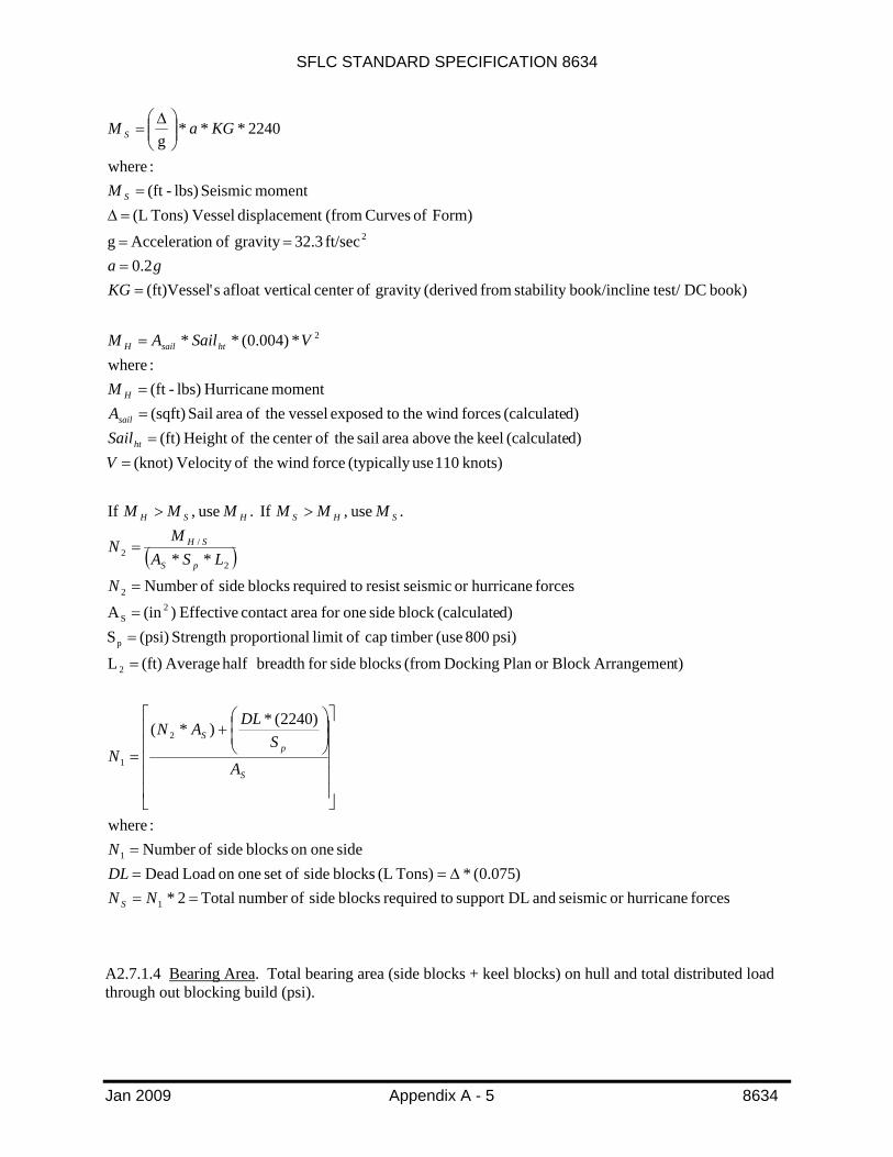
A2.7.1.3 Side Blocks. The number of side blocks required to meet seismic and hurricane overturning moments with dead loads included at 15% of total load.
SFLC STANDARD SPECIFICATION 8634
Jan 2009 Appendix A - 5 8634
( )
forces hurricaneor seismic and DLsupport torequired blocks side ofnumber Total 2*)075.0(*Tons) (L blocks side ofset oneon Load Dead
side oneon blocks side ofNumber :where
)2240(*)*(
t)ArrangemenBlock or Plan Docking (from blocks sidefor breadth half Average (ft) L
psi) 800 (use timber cap oflimit alproportionStrength (psi) Sd)(calculateblock side onefor areacontact Effective )(in A
forces hurricaneor seismicresist torequired blocks side ofNumber
**
. use , If . use , If
knots) 110 use (typically force wind theofVelocity (knot) d)(calculate keel theabove area sail theofcenter theofHeight (ft) d)(calculate forces wind the toexposed vessel theof area Sail (sqft)
moment Hurricane lbs) -(ft :where
*)004.0(**
book) DC test/ nebook/inclistability from (derivedgravity ofcenter ticalafloat ver s'(ft)Vessel 2.0
ft/sec 32.3 gravity ofon Accelerati gForm) of Curves (fromnt displaceme Vessel Tons) (L
moment Seismic lbs) -(ft :where
2240***g
1
1
2
1
2
p
2S
2
2
/2
2
2
==Δ==
=
⎥⎥⎥⎥⎥
⎦
⎤
⎢⎢⎢⎢⎢
⎣
⎡⎟⎟⎠
⎞⎜⎜⎝
⎛+
=
=
==
=
=
>>
==
==
=
==
==
=Δ=
⎟⎟⎠
⎞⎜⎜⎝
⎛ Δ=
NNDLN
A
SDLAN
N
N
LSAM
N
MMMMMM
VSailAM
VSailAM
KGga
M
KGaM
S
S
pS
pS
SH
SHSHSH
ht
sail
H
htsailH
S
S
A2.7.1.4 Bearing Area. Total bearing area (side blocks + keel blocks) on hull and total distributed load through out blocking build (psi).

SFLC STANDARD SPECIFICATION 8634
Jan 2009 Appendix A - 6 8634
( ) ( )
d)(calculate area bearing Total )(in Form) of Curves (fromnt displaceme Vessel Tons) (L
:where
*2240 (psi) Load dDistribute
d)(calculateblock side onefor areacontact Effective )(in
d)(calculate blocks side ofnumber Total d)(calculateblock keel onefor areacontact Effective )(in
plan) docking (from blocks keel ofnumber Total:where
**)(
2
2
2
2
=
=Δ
Δ=
=
==
=
+=
aBearingAre
aBearingAre
A
NA
N
ANANinea Bearing Ar
s
s
k
k
sskk
A2.7.1.5 Timber Stress. The Contractor shall provide the safe allowable block timber stresses for side blocks and keel blocks loading. The permissible compressive stress, listed below, shall be used when considering side and keel block bearing loads applied to the blocking. The proportional limit loads are to be used when calculating the block stress due to overturning moments.
WOOD PROPERTIES
Block Material
Permissible Compressive Stress Perpendicular to the grain (psi)
Permissible Compressive Stress Parallel to the grain (psi)
Proportional limit Perpendicular to the grain (psi)
SOFTWOOD
Douglas Fir 400 1400 800
Yellow Pine 300 900 700
HARDWOOD
Red & White Oak 600 1300 1300
A2.7.1.6 Additional blocks. As needed, the Contractor shall propose additional keel and/or side blocks, to support underwater hull work ensuring that timber block loading is not exceeded. Be aware that additional blocking shall be considered an alternate blocking arrangement.
A2.7.1.7 Alternate blocking arrangement. As needed, the Contractor shall submit an alternate blocking arrangement for approval to the COTR. An alternate blocking arrangement is required when the vessel's docking plan does not match the drydock structural limitations or when the keel/bilge blocks are considered interferences to scheduled work. When an alternate blocking plan is required the Contractor shall ensure that final block positions are adequately supported from both dock and ship structures. All

SFLC STANDARD SPECIFICATION 8634
Jan 2009 Appendix A - 7 8634
calculation requirements shall be met using the alternate blocking arrangement.
NOTE
A safe overhang is considered to be 1.5 to 2 times the molded depth of the vessel at the forward of aft most keel block for the bow or stern, respectively.
A2.7.2 Stability during docking/undocking.
A2.7.2.1 Draft at landing. The draft at landing, for a vessel with trim (typically down by the stern), shall be calculated to ensure the bow has fully landed prior to slacking mooring lines and hauling side blocks. As the force exerted by the keel block at the knuckle point takes on the weight (displacement) of the vessel and the buoyancy forces are reduced, the waterline along the length of the vessel’s hull will recede as if it has fully landed, this is prior to the bow actually landing. This reaction can create a “false landing” effect and if acted upon, with slacking the handling lines and/or hauling side blocks to early, can cause the blocks to be positioned incorrectly on the hull.
( )
Form) of Curves (fromimmersion inch per Tons inTon L
d)(calculatereaction Knuckle Tons) (Ldockingat vesselofdraft Mean (ft)
Landingat Draft (ft) :where
*12
⎟⎠⎞
⎜⎝⎛=
===
−=
TPI
RDD
TPIR
DD
kn
m
l
knml
A2.7.2.2 Stability at landing. The stability at landing shall be calculated to ensure the vessel maintains adequate stability during the docking evolution. At landing the effect of the force from the keel blocks on the vessel is essentially the same as reducing the weight of the vessel at the keel level. This effectively reduces the vessel’s GM (stability index) during the landing.
( )( )
d)(calculatereaction Knuckle Tons) (L book) DC test/ nebook/inclistability from (derivedgravity ofcenter ticalafloat ver sVessel' (ft)
Form) of Curves (fromdraft mean at nt displacemeafloat sVessel' Tons) (LForm) of Curves (fromdraft mean at keel theaboveheight cmetacentriafloat sVessel' (ft)
landingat index) (stabilityheight cmetacentri e transversCorrected (ft) :where
*
==
=Δ=
=
−ΔΔ
−=
kn
corr
kncorr
RKG
KMGM
RKGKMGM
A2.7.2.3 Draft at instability. The draft at instability for the vessel shall be included in the calculations. After the vessel’s keel has landed, the waterline on the hull continues to recede. As the weight of the vessel continues to increase on the keel blocks and buoyancy forces reduce, the effective GM (stability index) continues to decrease. At the draft at instability the vessel’s virtual GM is equal to zero (0) feet. The vessel may take on an appreciable angle of list at this draft.

SFLC STANDARD SPECIFICATION 8634
Jan 2009 Appendix A - 8 8634
To calculate the draft at instability, hydrostatic data from several drafts both greater and less than the mean draft shall be required. Start with the mean draft of the vessel afloat, then use a draft of one foot above through 2 ft below the mean draft, e.g. Dm = 5 ft, use data points for drafts at 6 ft, 5 ft, 4 ft, and 3 ft. Using the Curves of Form collect data points for LCF, MT1”, Displacement, and KM.
Next determine Xkn , the distance from aft edge of Keel Block No. 1 (KB1) to the LCF, for each of the drafts.
Then determine Rkn, the knuckle reaction, as calculated above, for each of the drafts.
Next determine the moment of residual buoyancy for each of the drafts using the equation below;
Form) of Curves (fromdraft each at height cMetacentri (ft) d)(calculatedraft each at reaction Knuckle Tons) (L
Form) of Curves (fromdraft each at nt displaceme Vessel Tons) (Ldrafteach at bouyancy residual ofMoment Tons) L-(ft
:where*)(
==
=Δ=
−Δ=
KMR
M
KMRM
kn
RB
knRB
Now, plot the MRB (x - axis) versus Draft (y - axis).
Then determine MGZ, the vessel’s afloat righting moment, a single point, using the equation below;
book) DC test/ nebook/inclistability from (derivedgravity ofcenter ticalafloat ver sVessel' (ft)Form) of Curves (from docking of at timent displacemeafloat Vessel Tons) (L
Moment Righting Tons) L-ft(:where
*MGZ
==Δ
=
Δ=
KG
M
KG
GZ
Now, plot the point for the resultant MGZ, using the MRB scale on the x – axis. Then draw a line over to the corresponding draft on the y – axis for the draft at instability. Below is an example of the graph.

SFLC STANDARD SPECIFICATION 8634
Jan 2009 Appendix A - 9 8634
Moment vs. Draft (EXAMPLE)
MRB
MRB
MRB
MRB
3
3.5
4
4.5
5
5.5
6
6.5
7
1.00 2.00 3.00 4.00Moment (Ft- L Tons) (x10^4)
Dra
fts (f
t)
MGZ
Draft at Instability
A2.7.2.4 Safety consideration for draft at landing. The Contractor shall calculate draft at landing to ensure it is no less than one (1) foot above the calculated draft at instability. In cases where this requirement may not be met, wither due to damage to the hull, emergency docking, etc., precautions for line handling and hauling blocks shall be put into the docking procedure to ensure that the vessel’s stability is maintained during the evolution. The precautions shall be discussed at the predocking conference.
A2.7.2.5 Bilge block hauling. When using hauled side blocks, the Contractor shall ensure the hauling occurs after the keel is fully landed and while the vessel’s GM is a minimum of one (1) foot. The vessel’s draft at the time of hauling blocks shall be at least 6 inches above the calculated draft at instability, so that there is full contact between all block caps and the hull well in advance of the draft at instability.
A2.7.2.6 Stabilizing Moment. For marine railways, building ways and vertical lifts, the Contractor shall submit additional calculations for both overturning and stabilizing moments. Ensure that the stabilizing moment is at least 25% greater than the overturning moment, also ensuring that moment calculations take into account both wind and current forces.

SFLC STANDARD SPECIFICATION 8634
Jan 2009 Appendix A - 10 8634
[ ]
Ostab
stab
stab
O
O
MM
bWM
bWM
AV
AVPAV
AVFhM
PFhM
*25.1
track theof Width (ft)cradle theof Weight (lbs)
Moment gStabilizin Tons) L -(ft :where
2*2240*
currentby pushed being vessel theof arear Underwate)(ft dockingfor forecast current theofVelocity (knots)
:re whe**004.0 current theof Force (lbs)
vessel theof area Sail )(ft dockingfor forecast wind theofVelocity (knots)
:re whe**004.0 wind theof Force (lbs)
track theof top theabove linesbreast ofHeight (ft) Moment gOverturnin Tons) L -(ft
:where2240*)(*
2
2
2
2
>
==
=
⎟⎠⎞
⎜⎝⎛=
=
=
==
=
=
==
==
+=
A2.7.2.7 Hoisting loads. For vertical lifts and cranes, the Contractor shall calculate the load on each strap or lifting cable. All strap loads shall be within 20% of each other. Ensure that the weight distribution of the vessel is considered for the lift. The lifting slings/straps shall be placed symmetrically about the vessel’s Longitudinal Center of Gravity (LCG). When lifting the vessel and buoyancy forces are off the hull, as practicable, the weight of the vessel shall be equally distributed to the forward and aft slings/straps.
A2.8 Floating drydock.
A2.8.1 Floating drydock stability. The Contractor shall demonstrate that the ship-dock system complies with the following GM requirements:
a. Docks with lifting capacities of 10,000 long tons (L Tons) or less, the minimum GM of ship/dock system shall be 5 feet for all portions of the planned lift. As a safety precaution, for conditions other than planned, the ship-dock system shall have a minimum GM of 2 feet with a level trim condition with the pontoon deck below the water surface.

SFLC STANDARD SPECIFICATION 8634
Jan 2009 Appendix A - 11 8634
b. Docks with capacities greater than 10,000 L Tons, the minimum GM shall be within the following range:
• 10,000 to 15,000 L Tons minimum GM of 4.8 feet. • 15,000 to 20,000 L Tons minimum GM of 4.5 feet. • 20,000 to 25,000 L Tons minimum GM of 4.3 feet. • 25,000 to 30,000 L Tons minimum GM of 4.1 feet. • 30,000 to 35,000 L Tons minimum GM of 3.9 feet. • 35,000 to 40,000 L Tons minimum GM of 3.7 feet. • 40,000 to 45,000 L Tons minimum GM of 3.4 feet • Greater than 50,000 L Tons minimum GM of 3.28 feet.
A2.8.2 Preparation of a pumping plan. The Contractor shall create and submit a pumping plan as a prerequisite for docking a Coast Guard vessel in a floating dock.
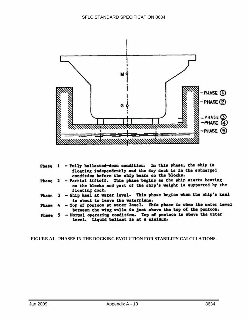
A2.8.2.1 Critical stages. The Contractor shall develop and submit a pumping plan to determine the tank levels for the five phases of operation on Figure A1. Special attention shall be given to the following stages:
• The vessel touches the blocks. • Stability of the vessel becomes critical. • Stability of vessel-dock system becomes critical.
A2.8.2.2 Proper pumping plans. The Contractor shall submit to the COTR a plan detailing the drydock tank levels for each phase of required stability calculations. Ensure that each tank is dewatered in proportion to the load distributed above the tank. Be aware that pressing up or emptying dock ballast tanks non-proportionally to obtain adequate GM, by minimizing free surface effect, is not acceptable.
A2.8.2.3 Objective. The Contractor shall prepare a pumping plan to satisfy, the following objectives using Figure A2 and Figure A3:
• Ensure that the dock has the required lifting capacity, to lift the vessel in its desired longitudinal position with respect to the dock, taking into account the residual silt and water in the tank.
• Ascertain that, during the docking evolution, neither the vessel by itself nor the vessel-dock combination will become unstable.
• Ensure that structural integrity of the dock will be maintained during the drydocking evolution:
• Ensure the longitudinal bending moment and the deflection remains within the acceptable range.
• Ensure in case of multi-section docks, the connections are not overstressed. • Ensure the bulkheads forming the tank boundaries will not be overstressed because of
excessive differential loading. • Ensure the blocking is not overloaded, with special consideration at the knuckle block load.
A2.8.2.4 Plan content. In order to satisfy these objectives, the pumping plan shall define: • The tank water levels after completion of drydocking.

SFLC STANDARD SPECIFICATION 8634
Jan 2009 Appendix A - 12 8634
• Water levels in the tanks at intermediate drafts of the drydock at which vessel stability status shall be checked.
• Observation to be made in the vessel at intermediate drafts. • Deflection gauge readings and draft boards to be checked at the intermediate drafts.
A2.8.2.5 Planning. The Contractor shall follow these steps in preparation of a pumping plan: • Examination of vessel data, including its docking drawing, curves of form and inclining
experiment or stability report. • Vessel survey provided by the COTR or vessel CO, including information on variable loads,
vessel’s drafts, and abnormalities (such as heavy lifts, trim, or hull damage). • Calculation of the vessel’s displacement and LCG at the time of docking, using arrival draft
readings. Calculation of all required changes to the variable loads onboard the vessel to correct for list, trim, and excessive free surface effects. Calculations shall include stability considerations described above.
• Dock survey, to determine effects of accumulated silt in tanks on available lifting capacity. • Examination of the required blocking arrangement, to determine the longitudinal location of
the vessel with respect to the dock and its center of gravity above the pontoon deck and structural supports.
A2.8.2.6 Distribution of lifting capacity (pumping plan). If strength and stability requirements are not violated, the amount of water that the Contractor shall remove from each tank may be calculated in advance. Be aware that a calculated pumping plan is for guidance only. The Dockmaster shall monitor the dock deflection and drafts during the evolution to ensure that the limits are not exceeded and account for the critical phases of operation. For large or sectional drydocks or when docking a vessel with extremely high loading at one end, the Contractor shall consider bending moments between tanks or dock sections in preparing the pumping plan. A properly prepared pumping plan typically results in a safer docking operation.
SFLC STANDARD SPECIFICATION 8634
Jan 2009 Appendix A - 13 8634
FIGURE A1 - PHASES IN THE DOCKING EVOLUTION FOR STABILITY CALCULATIONS.

SFLC STANDARD SPECIFICATION 8634
Jan 2009 Appendix A - 14 8634
FIGURE A2 - VESSEL LOAD DISTRIBUTION ON DOCK.

SFLC STANDARD SPECIFICATION 8634
Jan 2009 Appendix A- 13 8634
FIGURE A3 - SAMPLE TABLE FOR WATER TO BE REMOVED FROM TANK FOR LIFTING A VESSEL.

SFLC STANDARD SPECIFICATION 8634
Jan 2009 Appendix B -1 8634
APPENDIX B
REQUIREMENTS FOR FACILITY INSPECTION
B1. SCOPE
B1.1 Intent. This appendix describes the particular requirements for a Contractor’s drydock facility to be inspected by either a Professional Engineer.
B2. REQUIREMENTS
B2.1 General. The Contractor’s Professional Engineer shall use the checklist provided in this appendix, to conduct an independent survey of the Contractor’s drydock facilities. The Contractor shall submit the completed and validated forms to KO.
B2.2 Validation for certification. The Contractor’s Professional Engineer shall witness an inspection and operational test of the Contractor’s drydock equipment and inspection of the Contractor’s facility, then record conditions using the checklists as formatted and detailed with in this Appendix. The Professional Engineer shall provide signed/sealed statement with their completed checklist to the Contractor, thereby attesting that the information within is valid, based on their professional judgment.
NOTE
The checklists provided with in this specification are formatted so that the Professional Engineer may obtain the necessary information for acceptance of the certification by USCG. The use of additional sheets, as necessary for
informational purposes, is acceptable.
B2.3 Cycle for certification. The Contractor shall be aware that the period by which the completed checklist shall be recorded as valid and accepted by USCG as certification shall be as stated below. Be aware that the inspection cycle is based on the age of the facility, excepting cradles (see B2.3.1 (Cycle for cradle certification)).
AGE OF FACILITY PERIODICITY
Less than 10 years 3 years Over 10 years 2 years
B2.3.1 Cycle for cradle certification. The Contractor shall be aware that the period by which the completed docking/lifting cradle checklist shall be recorded as valid and accepted by USCG as certification shall be every four years.
B2.4 Applicability. The “General Requirements” inspection checklist sheets are required for all types of facilities, except in the case of cradles. The additional sheets are specific to the type of facility to be certified. Be aware that the each type of facility owned and operated by the Contractor shall have individual certifications.

SFLC STANDARD SPECIFICATION 8634
Jan 2009 Appendix B -2 8634
INSPECTION CHECKLISTS FOR DRYDOCKING FACILITIES CERTIFICATION
The following is a list of the minimum facility requirements with integrated inspection checklists for each type of drydocking facility. All required equipment or equipment that the Contractor intends to use must be marked satisfactory at the time of the availability start date.
I hereby certify the material and operational conditions of the docking facilities identified as ________________________, owned and operated by ____________________________, are safe for docking vessels within the facility's rated capacity on this the __________day of ___________________, in the year of __________.
Date: ______________________
Registration State and No.: __________________________________________
Signature of Registered Professional Engineer: __________________________________________
SFLC STANDARD SPECIFICATION 8634
Jan 2009 Appendix B -3 8634
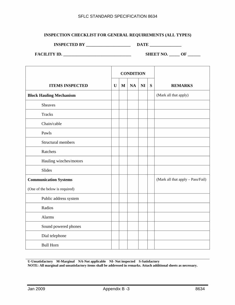
INSPECTION CHECKLIST FOR GENERAL REQUIREMENTS (ALL TYPES)
INSPECTED BY _____________________ DATE _______________
FACILITY ID. ________________________________ SHEET NO. _____ OF ______
CONDITION
ITEMS INSPECTED U M NA NI S REMARKS
Block Hauling Mechanism (Mark all that apply)
Sheaves
Tracks
Chain/cable
Pawls
Structural members
Ratchets
Hauling winches/motors
Slides
Communication Systems
(One of the below is required)
(Mark all that apply – Pass/Fail)
Public address system
Radios
Alarms
Sound powered phones
Dial telephone
Bull Horn
U-Unsatisfactory M-Marginal NA-Not applicable NI- Not inspected S-Satisfactory NOTE: All marginal and unsatisfactory items shall be addressed in remarks. Attach additional sheets as necessary.

SFLC STANDARD SPECIFICATION 8634
Jan 2009 Appendix B -4 8634
INSPECTION CHECKLIST FOR GENERAL REQUIREMENTS (ALL TYPES), CONTINUED
INSPECTED BY _____________________ DATE _______________
FACILITY ID. ________________________________ SHEET NO. _____ OF ______
CONDITION
ITEMS INSPECTED U M NA NI S REMARKS
Electrical Systems and Equipment
Electrical power system shall support maximum load, developed by simultaneous operation of the dewatering pumps, fire protection pumps, valve opening and closing mechanisms, hauling machinery, communications equipment, lighting, alarms, and any other support equipment or systems necessary for the safe operation of the facility.
Main power source (One of the below is required)
(Required)
Shore power
Diesel gen. Set
Back-up power source (Optional)
Shore power
Diesel gen. Sets
Electrical power distribution (Required)
Lighting for operations & security (Required)
Ship grounding straps (Required)
Welding machine grounds (Required)
FIRE PROTECTION SYSTEM (One of the below is required)
(Required)
Installed fire protection system compliant with Occupational Safety and Health Administration (OSHA) regulations
Memorandum of agreement with a local fire department ensuring that that fire department can arrive at the facility within 30 minutes of receiving the alarm.
U-Unsatisfactory M-Marginal NA-Not applicable NI- Not inspected S-Satisfactory NOTE: All marginal and unsatisfactory items shall be addressed in remarks. Attach additional sheets as necessary.

SFLC STANDARD SPECIFICATION 8634
Jan 2009 Appendix B -5 8634
INSPECTION CHECKLIST FOR GENERAL REQUIREMENTS (ALL TYPES), CONTINUED
FACILITY ID. ________________________________ SHEET NO. _____ OF ______
CONDITION
ITEMS INSPECTED U M NA NI S REMARKS
FITTINGS/CONNECTIONS (Mark all that apply)
Cleats
Bollards
Chocks
Gratings
Ringbolts
Platforms
Watertight doors, hatches, portlights and manholes
Gudgeon and pintle connections
Bolted connections
Attachments
Reinforcements
SHIP/DOCK HANDLING SYSTEMS AND EQUIPMENT (One of the below is required)
(Mark all that apply)
Capstans
Winches
Trolleys
Translation chains and cables
UNDERWATER INSPECTION Has there been an inspection performed within the last 5 years?
(Required)
U-Unsatisfactory M-Marginal NA-Not applicable NI- Not inspected S-Satisfactory NOTE: All marginal and unsatisfactory items shall be addressed in remarks. Attach additional sheets as necessary.
SFLC STANDARD SPECIFICATION 8634
Jan 2009 Appendix B -6 8634
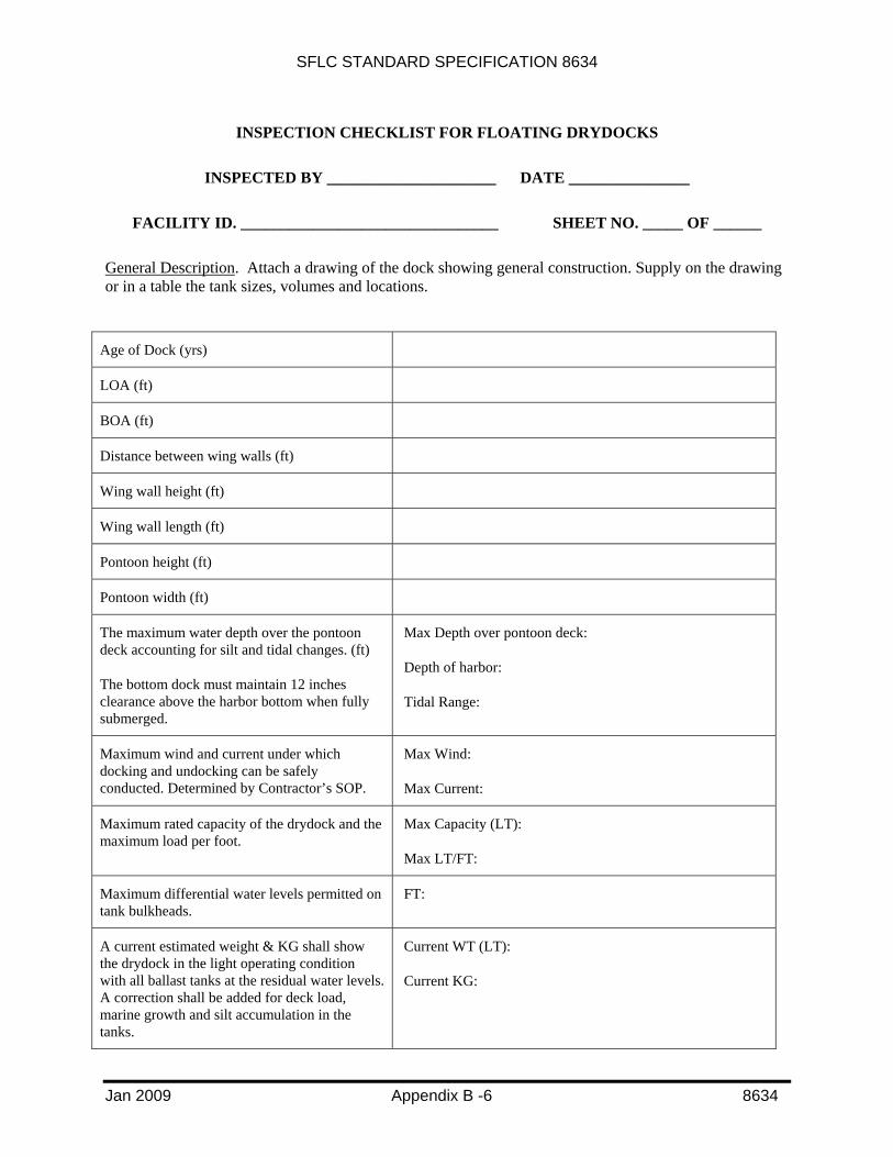
INSPECTION CHECKLIST FOR FLOATING DRYDOCKS
INSPECTED BY _____________________ DATE _______________
FACILITY ID. ________________________________ SHEET NO. _____ OF ______
General Description. Attach a drawing of the dock showing general construction. Supply on the drawing or in a table the tank sizes, volumes and locations.
Age of Dock (yrs)
LOA (ft)
BOA (ft)
Distance between wing walls (ft)
Wing wall height (ft)
Wing wall length (ft)
Pontoon height (ft)
Pontoon width (ft)
The maximum water depth over the pontoon deck accounting for silt and tidal changes. (ft)
The bottom dock must maintain 12 inches clearance above the harbor bottom when fully submerged.
Max Depth over pontoon deck:
Depth of harbor:
Tidal Range:
Maximum wind and current under which docking and undocking can be safely conducted. Determined by Contractor’s SOP.
Max Wind:
Max Current:
Maximum rated capacity of the drydock and the maximum load per foot.
Max Capacity (LT):
Max LT/FT:
Maximum differential water levels permitted on tank bulkheads.
FT:
A current estimated weight & KG shall show the drydock in the light operating condition with all ballast tanks at the residual water levels. A correction shall be added for deck load, marine growth and silt accumulation in the tanks.
Current WT (LT):
Current KG:

SFLC STANDARD SPECIFICATION 8634
Jan 2009 Appendix B -7 8634
NSPECTION CHECKLIST FOR FLOATING DRYDOCKS, CONTINUED
FACILITY ID. ________________________________ SHEET NO. _____ OF ______
CONDITION
ITEMS INSPECTED U M NA NI S REMARKS
BALLASTING SYSTEM (Required)
Do pumps operate? (Pass/Fail)
Ballast and deballast in less than eight hours.
(Pass/Fail)
Do valves operate? (Pass/Fail)
DEFLECTION DETECTION SYSTEM (Describe system if applicable)
(Optional)
DRAFT BOARDS Draft boards showing depth of water over pontoon deck at the wingwalls near the four inboard corners and at mid-length on the port and starboard sides.
(Required - Pass/Fail)
METHOD FOR DETERMINING TANK LEVELS
(Mark all that apply. One of the below is required)
Tank level indicators
Sounding tubes
HULL STRUCTURE Metal structural members shall have no more than 25% wastage. Wood structural members shall be free of wood rot, marine bores and deemed in good condition.
Pontoon deck
Pontoon sides/ends
Pontoon bottom
Wingwalls sides/ends
Wingwall top deck
Safety/machinery decks
Interior Ballast/trim/ buoyancy tanks
U-Unsatisfactory M-Marginal NA-Not applicable NI- Not inspected S-Satisfactory Note: All marginal and unsatisfactory items shall be addressed in remarks. Attach additional sheets as necessary.
SFLC STANDARD SPECIFICATION 8634
Jan 2009 Appendix B -8 8634
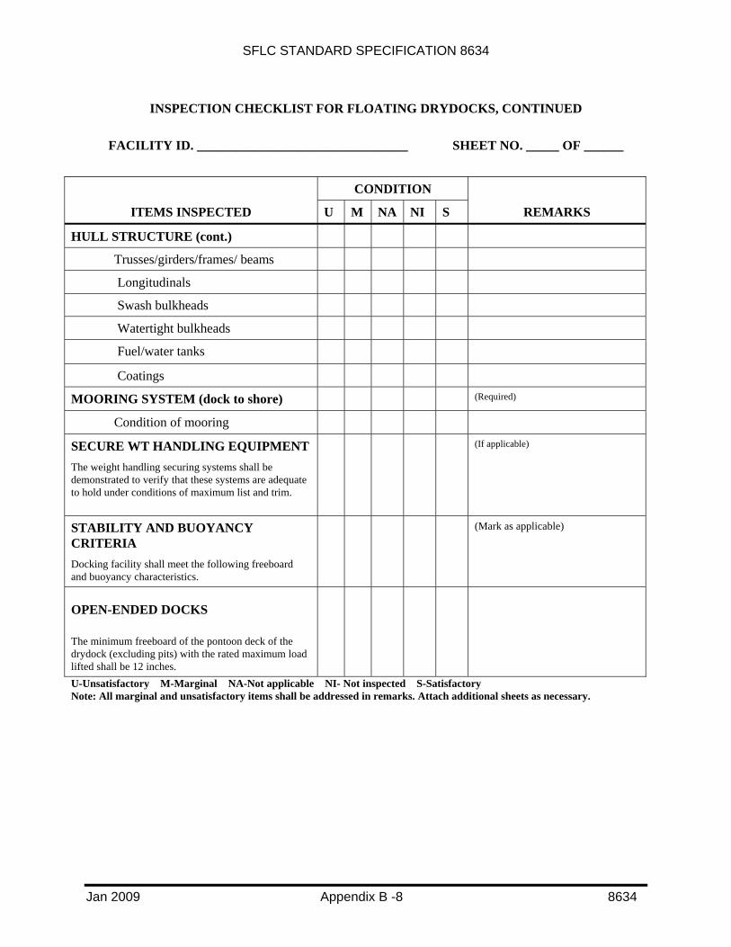
INSPECTION CHECKLIST FOR FLOATING DRYDOCKS, CONTINUED
FACILITY ID. ________________________________ SHEET NO. _____ OF ______
CONDITION
ITEMS INSPECTED U M NA NI S REMARKS
HULL STRUCTURE (cont.)
Trusses/girders/frames/ beams
Longitudinals
Swash bulkheads
Watertight bulkheads
Fuel/water tanks
Coatings
MOORING SYSTEM (dock to shore) (Required)
Condition of mooring
SECURE WT HANDLING EQUIPMENT The weight handling securing systems shall be demonstrated to verify that these systems are adequate to hold under conditions of maximum list and trim.
(If applicable)
STABILITY AND BUOYANCY CRITERIA Docking facility shall meet the following freeboard and buoyancy characteristics.
(Mark as applicable)
OPEN-ENDED DOCKS
The minimum freeboard of the pontoon deck of the drydock (excluding pits) with the rated maximum load lifted shall be 12 inches.
U-Unsatisfactory M-Marginal NA-Not applicable NI- Not inspected S-Satisfactory Note: All marginal and unsatisfactory items shall be addressed in remarks. Attach additional sheets as necessary.

SFLC STANDARD SPECIFICATION 8634
Jan 2009 Appendix B -9 8634
INSPECTION CHECKLIST FOR FLOATING DRYDOCKS, CONTINUED
FACILITY ID. ________________________________ SHEET NO. _____ OF ______
CONDITION
ITEMS INSPECTED U M NA NI S REMARKS
CLOSE-ENDED DRY DOCK
Minimum freeboard with the rated maximum load lifted shall be nine inches, measured from the sill of the stern (or bow) gates.
FLOATING DRYOCKS IN THE FULLY BALLASTED DOWN CONDITION
During controlled ballasting of the drydock, the minimum freeboard (measured from the top deck at side) shall be 12 inches.
Required (Pass/Fail)
EMERGENCY PUMPING PLAN The facility must have an emergency plan or data demonstrating that failure of a pump or loss of pumping capacity will neither put the drydock out of operation nor cause damage to either the drydock or a ship in drydock.
Required (Pass/Fail)
U-Unsatisfactory M-Marginal NA-Not applicable NI- Not inspected S-Satisfactory Note: All marginal and unsatisfactory items shall be addressed in remarks. Attach additional sheets as necessary.
SFLC STANDARD SPECIFICATION 8634
Jan 2009 Appendix B -10 8634
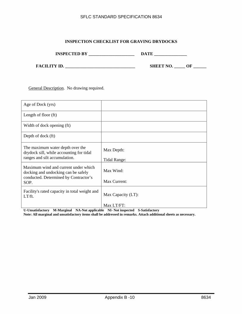
INSPECTION CHECKLIST FOR GRAVING DRYDOCKS
INSPECTED BY _____________________ DATE _______________
FACILITY ID. ________________________________ SHEET NO. _____ OF ______
General Description. No drawing required.
Age of Dock (yrs)
Length of floor (ft)
Width of dock opening (ft)
Depth of dock (ft)
The maximum water depth over the drydock sill, while accounting for tidal ranges and silt accumulation.
Max Depth:
Tidal Range:
Maximum wind and current under which docking and undocking can be safely conducted. Determined by Contractor’s SOP.
Max Wind:
Max Current:
Facility's rated capacity in total weight and LT/ft. Max Capacity (LT):
Max LT/FT: U-Unsatisfactory M-Marginal NA-Not applicable NI- Not inspected S-Satisfactory Note: All marginal and unsatisfactory items shall be addressed in remarks. Attach additional sheets as necessary.
SFLC STANDARD SPECIFICATION 8634
Jan 2009 Appendix B -11 8634
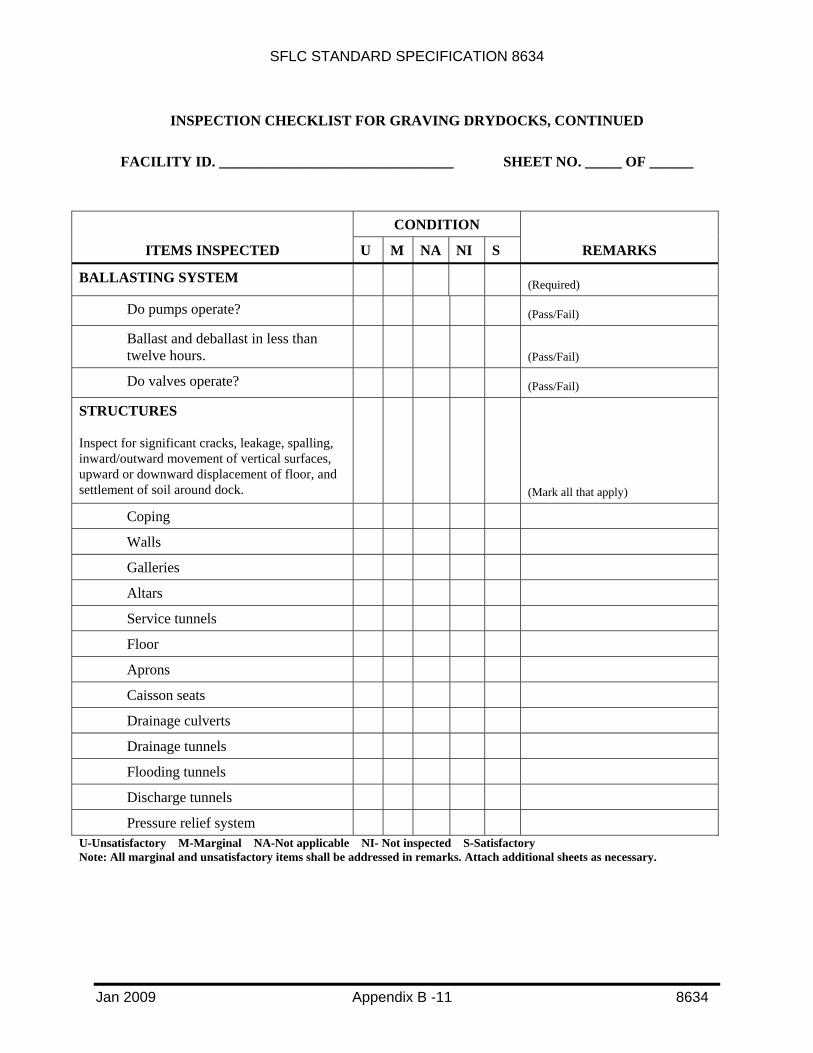
INSPECTION CHECKLIST FOR GRAVING DRYDOCKS, CONTINUED
FACILITY ID. ________________________________ SHEET NO. _____ OF ______
CONDITION
ITEMS INSPECTED U M NA NI S REMARKS
BALLASTING SYSTEM (Required)
Do pumps operate? (Pass/Fail)
Ballast and deballast in less than twelve hours.
(Pass/Fail)
Do valves operate? (Pass/Fail)
STRUCTURES
Inspect for significant cracks, leakage, spalling, inward/outward movement of vertical surfaces, upward or downward displacement of floor, and settlement of soil around dock.
(Mark all that apply)
Coping
Walls
Galleries
Altars
Service tunnels
Floor
Aprons
Caisson seats
Drainage culverts
Drainage tunnels
Flooding tunnels
Discharge tunnels
Pressure relief system
U-Unsatisfactory M-Marginal NA-Not applicable NI- Not inspected S-Satisfactory Note: All marginal and unsatisfactory items shall be addressed in remarks. Attach additional sheets as necessary.

SFLC STANDARD SPECIFICATION 8634
Jan 2009 Appendix B -12 8634
INSPECTION CHECKLIST FOR GRAVING DRYDOCKS, CONTINUED
FACILITY ID. ________________________________ SHEET NO. _____ OF ______
CONDITION
ITEMS INSPECTED U M NA NI S REMARKS
CAISSON (Required)
Shell plating/Sheathing
Structural framing
Bulkheads
Deck plating
Top deck coverings
Fenders
Backing for seals
Seals
Fixed ballast
DRAFT BOARDS
Draft boards showing depth of water over dock floor near the four inboard corners and at mid-length on the port and starboard sides.
(Pass/Fail)
PUMP HOUSES General Condition (Pass/Fail)
U-Unsatisfactory M-Marginal NA-Not applicable NI- Not inspected S-Satisfactory NOTE: All marginal and unsatisfactory items shall be addressed in remarks. Attach additional sheets as necessary.

SFLC STANDARD SPECIFICATION 8634
Jan 2009 Appendix B -13 8634
INSPECTION CHECKLIST FOR MARINE RAILWAY
INSPECTED BY _____________________ DATE _______________
FACILITY ID. ________________________________ SHEET NO. _____ OF ______
General Description. No drawing required.
Age of dock (yrs)
LOA of cradle (ft)
Width between wingwalls of cradle (ft)
Width between rails (ft)
The maximum water depth over the cradle baseline, while accounting for silting and tidal ranges.
Max Depth:
Tidal Range:
Maximum wind and current under which docking and undocking can be safely conducted. Determined by Contractor’s SOP.
Max Wind:
Max Current:
Facility's rated capacity in total weight and LT/ft.
Max Capacity (LT):
Max LT/FT:
U-Unsatisfactory M-Marginal NA-Not applicable NI- Not inspected S-Satisfactory NOTE: All marginal and unsatisfactory items shall be addressed in remarks. Attach additional sheets as necessary.

SFLC STANDARD SPECIFICATION 8634
Jan 2009 Appendix B -14 8634
INSPECTION CHECKLIST FOR MARINE RAILWAYS, CONTINUED
FACILITY ID. ________________________________ SHEET NO. _____ OF ______
CONDITION ITEMS INSPECTED U M NA NI S REMARKS
CRADLES (Required) General conditions Decking Block bearers Elevated frameworks Under deck frameworks Drawhead girder Bottom chords Bitumastic enamel on steel Preservative on wood Wheel bearing supports
DRAFT BOARDS Draft boards showing depth of water over cradle floor at the wingwalls near the four inboard corners and at mid-length on the port and starboard sides.
(Pass/Fail)
GROUNDWAYS & RAILS Inspect above water portion and splash zone
(Required)
Alignment of tracks Settlement of tracks Piles Stringers Cross bracing Track plates & fasteners Rail & fasteners Chain guides
U-Unsatisfactory M-Marginal NA-Not applicable NI- Not inspected S-Satisfactory NOTE: All marginal and unsatisfactory items shall be addressed in remarks. Attach additional sheets as necessary.
SFLC STANDARD SPECIFICATION 8634
Jan 2009 Appendix B -15 8634
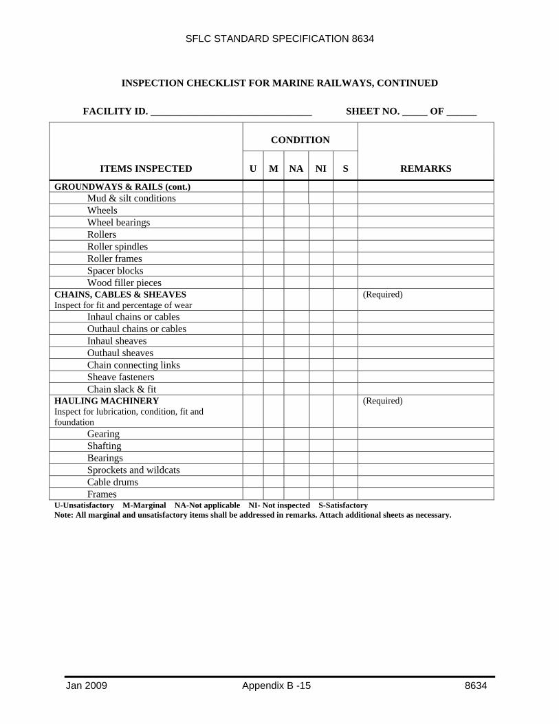
INSPECTION CHECKLIST FOR MARINE RAILWAYS, CONTINUED
FACILITY ID. ________________________________ SHEET NO. _____ OF ______
CONDITION
ITEMS INSPECTED U M NA NI S REMARKS
GROUNDWAYS & RAILS (cont.) Mud & silt conditions Wheels Wheel bearings Rollers Roller spindles Roller frames Spacer blocks Wood filler pieces
CHAINS, CABLES & SHEAVES Inspect for fit and percentage of wear
(Required)
Inhaul chains or cables Outhaul chains or cables Inhaul sheaves Outhaul sheaves Chain connecting links Sheave fasteners Chain slack & fit
HAULING MACHINERY Inspect for lubrication, condition, fit and foundation
(Required)
Gearing Shafting Bearings Sprockets and wildcats Cable drums Frames
U-Unsatisfactory M-Marginal NA-Not applicable NI- Not inspected S-Satisfactory Note: All marginal and unsatisfactory items shall be addressed in remarks. Attach additional sheets as necessary.

SFLC STANDARD SPECIFICATION 8634
Jan 2009 Appendix B -16 8634
INSPECTION CHECKLIST FOR MARINE RAILWAYS, CONTINUED
FACILITY ID. ________________________________ SHEET NO. _____ OF ______
CONDITION
ITEMS INSPECTED U M NA NI S REMARKS
HAULING MACHINERY (cont.)
Electric Brakes
Hand brakes
Locking pawls
Clutches
Safety guards
Electric motors
Diesels/gas engines
Steam/compressed air drives
Controllers
Speed limit devices
Control boards
Switches
Safety devices & alarms
U-Unsatisfactory M-Marginal NA-Not applicable NI- Not inspected S-Satisfactory NOTE: All marginal and unsatisfactory items shall be addressed in remarks. Attach additional sheets as necessary.

SFLC STANDARD SPECIFICATION 8634
Jan 2009 Appendix B -17 8634
INSPECTION CHECKLIST FOR VERTICAL LIFTS
INSPECTED BY _____________________ DATE _______________
FACILITY ID. ________________________________ SHEET NO. _____ OF ______
General Description. No drawing required.
Age of dock (yrs)
LOA of platform (ft)
BOA of platform (ft)
Width between rails (ft)
The maximum water depth over the lifting platform, while accounting for tidal ranges and silt accumulation.
Max Depth:
Tidal Range:
Maximum wind and current under which docking and undocking can be safely conducted. Determined by Contractor’s SOP.
Max Wind:
Max Current:
Facility's rated capacity in total weight and LT/ft.
Max Capacity (LT):
Max (LT/FT):
U-Unsatisfactory M-Marginal NA-Not applicable NI- Not inspected S-Satisfactory NOTE: All marginal and unsatisfactory items shall be addressed in remarks. Attach additional sheets as necessary.

SFLC STANDARD SPECIFICATION 8634
Jan 2009 Appendix B -18 8634
INSPECTION CHECKLIST FOR VERTICAL LIFTS, CONTINUED
FACILITY ID. ________________________________ SHEET NO. _____ OF ______
CONDITION
ITEMS INSPECTED U M NA NI S REMARKS
HOIST Inspect for unusual running noises, lubrication, condition of wire rope, and foundations
(Required) Motors Gears Brakes Wire ropes More than 2 broken wires per
wire rope requires replacement. Bearings Drums Foundation platform Anchorage Piles Lubrication system Wiring
PLATFORM Inspect for soundness of structure
(Required)
Main transverse beams Secondary transverse beams Longitudinal beams Stiffeners Decking Sheaves Bearings Sheave housings Tracks
U-Unsatisfactory M-Marginal NA-Not applicable NI- Not inspected S-Satisfactory NOTE: All marginal and unsatisfactory items shall be addressed in remarks. Attach additional sheets as necessary.

SFLC STANDARD SPECIFICATION 8634
Jan 2009 Appendix B -19 8634
INSPECTION CHECKLIST FOR VERTICAL LIFTS, CONTINUED
FACILITY ID. ________________________________ SHEET NO. _____ OF ______
CONDITION
ITEMS INSPECTED U M NA NI S REMARKS
PLATFORM (cont)
Inspect for soundness of structure
(Required)
Pins Tracks
CRADLES
Inspect for soundness of structure
(Required)
Main transverse beams
Secondary transverse beams
Stiffeners
Longitudinal beams
Wheels/rollers/roller plates
Roller spindles/wheel axles
Block bearers
TRANSFER SYSTEM Inspect for unevenness in heights of tracks, excessive corrosion, hitching mechanism
(Required)
Tracks
Hauling device
U-Unsatisfactory M-Marginal NA-Not applicable NI- Not inspected S-Satisfactory NOTE: All marginal and unsatisfactory items shall be addressed in remarks. Attach additional sheets as necessary.
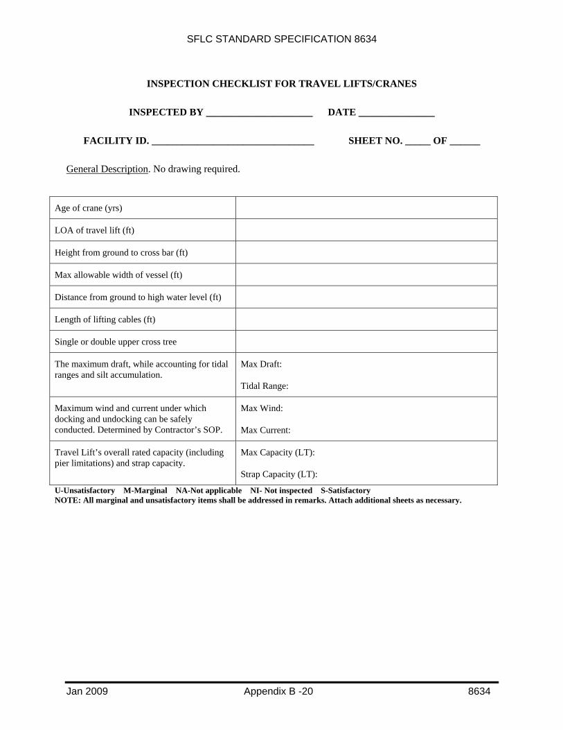
SFLC STANDARD SPECIFICATION 8634
Jan 2009 Appendix B -20 8634
INSPECTION CHECKLIST FOR TRAVEL LIFTS/CRANES
INSPECTED BY _____________________ DATE _______________
FACILITY ID. ________________________________ SHEET NO. _____ OF ______
General Description. No drawing required.
Age of crane (yrs)
LOA of travel lift (ft)
Height from ground to cross bar (ft)
Max allowable width of vessel (ft)
Distance from ground to high water level (ft)
Length of lifting cables (ft)
Single or double upper cross tree
The maximum draft, while accounting for tidal ranges and silt accumulation.
Max Draft:
Tidal Range:
Maximum wind and current under which docking and undocking can be safely conducted. Determined by Contractor’s SOP.
Max Wind:
Max Current:
Travel Lift’s overall rated capacity (including pier limitations) and strap capacity.
Max Capacity (LT):
Strap Capacity (LT):
U-Unsatisfactory M-Marginal NA-Not applicable NI- Not inspected S-Satisfactory NOTE: All marginal and unsatisfactory items shall be addressed in remarks. Attach additional sheets as necessary.

SFLC STANDARD SPECIFICATION 8634
Jan 2009 Appendix B -21 8634
INSPECTION CHECKLIST FOR TRAVEL LIFTS/CRANES, CONTINUED
FACILITY ID. ________________________________ SHEET NO. _____ OF ______
CONDITION
ITEMS INSPECTED U M NA NI S REMARKS
DRIVE MECHANISM Inspect brakes, tires, wheels, bearing, emergency brake
(Required)
Hoist (Required) Transmission motor & Brake Emergency Brake Trolley & hoist block Transverse reducer and motor Wire Straps/Slings/Preventers Sheaves
Drum Minimum of two wraps on drum
at lowest position HYDRAULICS Hoses, fittings, tank, motor, valves, pump & fluid levels
(Required)
ENVIRONMENT (Required) Overhead clearance Road surface Final blocking surface
STRUCTURE Top Beam, column platform, side beam
(Required)
U-Unsatisfactory M-Marginal NA-Not applicable NI- Not inspected S-Satisfactory NOTE: All marginal and unsatisfactory items shall be addressed in remarks. Attach additional sheets as necessary.

SFLC STANDARD SPECIFICATION 8634
Jan 2009 Appendix B -22 8634
INSPECTION CHECKLIST FOR TRAVEL LIFTS/CRANES, CONTINUED
FACILITY ID. ________________________________ SHEET NO. _____ OF ______
CONDITION
ITEMS INSPECTED U M NA NI S REMARKS
PIER FACILITY (Required)
Surface Condition
Pilings
Stops
LOAD TEST (Required)
Load applied:
Date of Test:
Rated Capacity:
U-Unsatisfactory M-Marginal NA-Not applicable NI- Not inspected S-Satisfactory NOTE: All marginal and unsatisfactory items shall be addressed in remarks. Attach additional sheets as necessary.

SFLC STANDARD SPECIFICATION 8634
Jan 2009 Appendix B -23 8634
INSPECTION CHECKLIST FOR DOCKING/LIFTING CRADLES
INSPECTED BY _____________________ DATE _______________
FACILITY ID. ________________________________ SHEET NO. _____ OF ______
General Description. Attach a drawing of cradle showing general construction if Coast Guard Drawing was not used as construction plan. Attach weld NDI test report.
Age of cradle (yrs)
Coast Guard Drawing used for construction plan (if applicable, otherwise attach drawing)
Type of cradle (if applicable, docking or lifting)
Position cradle built in (if applicable, Pos. 1 or Pos. 2)
LOA of cradle (ft)
BOA of cradle (ft)
Weight of cradle (LT)
The maximum water depth over the cradle (from point of highest bilge block), while accounting for tidal ranges and silt accumulation.
Max Depth:
Tidal Range:
Maximum wind and current under which docking and undocking can be safely conducted. Determined by Contractor’s SOP.
Max Wind:
Max Current:
Cradle’s rated capacity in total weight and LT/ft.
Max Capacity (LT):
Max Capacity (LT/ft):
U-Unsatisfactory M-Marginal NA-Not applicable NI- Not inspected S-Satisfactory NOTE: All marginal and unsatisfactory items shall be addressed in remarks. Attach additional sheets as necessary.

SFLC STANDARD SPECIFICATION 8634
Jan 2009 Appendix B -24 8634
INSPECTION CHECKLIST FOR DOCKING/LIFTING CRADLES, CONTINUED
FACILITY ID. ________________________________ SHEET NO. _____ OF ______
CONDITION
ITEMS INSPECTED U M NA NI S REMARKS
STRUCTURE
Inspect both cradle and spreader bar, as applicable
(Required)
General Condition
Bilge Block Supports
Vertical Guide Posts
Weld Joints (Attach NDI test report)
Bolt Joints
Bolts
Drain Plugs Removed and Inspect Bilge Block Supports
Drain Plugs Removed and Inspect Spreader Bar and Sway Brace Interior
Pad Eyes
Centering Track Alignment Check
Preservation on Steel Sections
LOAD TEST (Required)
Load applied:
Date of Test:
Rated Capacity:
U-Unsatisfactory M-Marginal NA-Not applicable NI- Not inspected S-Satisfactory NOTE: All marginal and unsatisfactory items shall be addressed in remarks. Attach additional sheets as necessary.

SFLC STANDARD SPECIFICATION 8634
Jan 2009 Appendix B -25 8634
INSPECTION CHECKLIST FOR BLOCK/CRADLE FOUNDATIONS (THAT ARE SEPARATE FROM CERTIFIED DOCK FLOORS)
INSPECTED BY _____________________ DATE _______________
FACILITY ID. ________________________________ SHEET NO. _____ OF ______
General Description. Attach a drawing of site showing general location, layout, and dimensions. Attach site survey, drainage plan, and geo-technical data.
Foundation composition description (i.e concrete, compacted gravel, asphalt, etc.)
Grade elevation (ft)
Maximum frost penetration depth (inches) (if applicable)
Water table elevation (ft)
Length of foundation site (ft)
Width of foundation site (ft)
Allowable bearing capacity (psf)
Calculated bearing pressure (psi)
U-Unsatisfactory M-Marginal NA-Not applicable NI- Not inspected S-Satisfactory NOTE: All marginal and unsatisfactory items shall be addressed in remarks. Attach additional sheets as necessary.

SFLC STANDARD SPECIFICATION 8634
Jan 2009 Appendix C -1 8634
APPENDIX C
REQUIREMENTS FOR DOCKING AND LIFTING CRADLES
C1. SCOPE
C1.1 Intent. This appendix describes the requirements for construction and testing of docking and lifting cradles, for 110/87-foot patrol boats.
C2. REQUIREMENTS
C2.1 Cradle option. If the Contractor chooses to drydock the designated patrol boat on a cradle, the Contractor shall ensure the following:
C2.1.1 Docking cradle. The docking cradle shall be constructed, as shown on the applicable Coast Guard Drawing:
VESSEL CLASS APPLICABLE COAST GUARD DRAWING
110 WPB 110 WPB 085-002, Shts 5-8 110 WPB 085-010
87 WPB 87 WPB 085-010 87 WPB 085-012
CAUTION!
Cradles for the 110 WPB built using Coast Guard Drawing 110 WPB 085-002 are classified as docking cradles only and cannot be used with crane or travel lift operations. Only cradles for the 110 WPB built using Coast Guard Drawing 110
WPB 085-010 can be used as either a docking or lifting cradle.
C2.1.2 Lifting cradle. The lifting cradle is similar to the docking cradle with additional pad eyes added to the structure to enable the cradle to be lifted with a crane or travel lift. The lifting cradle shall be constructed, as shown on the applicable Coast Guard Drawing:
VESSEL CLASS APPLICABLE COAST GUARD DRAWING
110 WPB 110 WPB 085-010 87 WPB 87 WPB 085-012
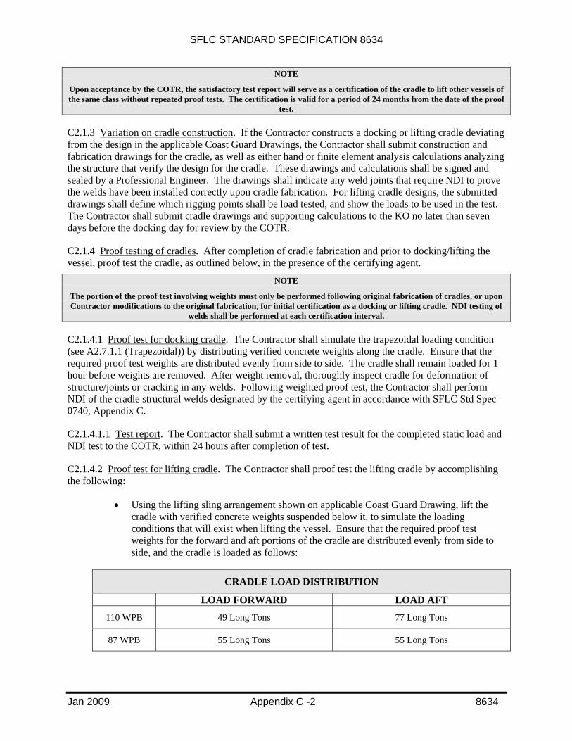
SFLC STANDARD SPECIFICATION 8634
Jan 2009 Appendix C -2 8634
NOTE
Upon acceptance by the COTR, the satisfactory test report will serve as a certification of the cradle to lift other vessels of the same class without repeated proof tests. The certification is valid for a period of 24 months from the date of the proof
test.
C2.1.3 Variation on cradle construction. If the Contractor constructs a docking or lifting cradle deviating from the design in the applicable Coast Guard Drawings, the Contractor shall submit construction and fabrication drawings for the cradle, as well as either hand or finite element analysis calculations analyzing the structure that verify the design for the cradle. These drawings and calculations shall be signed and sealed by a Professional Engineer. The drawings shall indicate any weld joints that require NDI to prove the welds have been installed correctly upon cradle fabrication. For lifting cradle designs, the submitted drawings shall define which rigging points shall be load tested, and show the loads to be used in the test. The Contractor shall submit cradle drawings and supporting calculations to the KO no later than seven days before the docking day for review by the COTR.
C2.1.4 Proof testing of cradles. After completion of cradle fabrication and prior to docking/lifting the vessel, proof test the cradle, as outlined below, in the presence of the certifying agent.
NOTE
The portion of the proof test involving weights must only be performed following original fabrication of cradles, or upon Contractor modifications to the original fabrication, for initial certification as a docking or lifting cradle. NDI testing of
welds shall be performed at each certification interval.
C2.1.4.1 Proof test for docking cradle. The Contractor shall simulate the trapezoidal loading condition (see A2.7.1.1 (Trapezoidal)) by distributing verified concrete weights along the cradle. Ensure that the required proof test weights are distributed evenly from side to side. The cradle shall remain loaded for 1 hour before weights are removed. After weight removal, thoroughly inspect cradle for deformation of structure/joints or cracking in any welds. Following weighted proof test, the Contractor shall perform NDI of the cradle structural welds designated by the certifying agent in accordance with SFLC Std Spec 0740, Appendix C.
C2.1.4.1.1 Test report. The Contractor shall submit a written test result for the completed static load and NDI test to the COTR, within 24 hours after completion of test.
C2.1.4.2 Proof test for lifting cradle. The Contractor shall proof test the lifting cradle by accomplishing the following:
• Using the lifting sling arrangement shown on applicable Coast Guard Drawing, lift the cradle with verified concrete weights suspended below it, to simulate the loading conditions that will exist when lifting the vessel. Ensure that the required proof test weights for the forward and aft portions of the cradle are distributed evenly from side to side, and the cradle is loaded as follows:
CRADLE LOAD DISTRIBUTION
LOAD FORWARD LOAD AFT
110 WPB 49 Long Tons 77 Long Tons
87 WPB 55 Long Tons 55 Long Tons

SFLC STANDARD SPECIFICATION 8634
Jan 2009 Appendix C -3 8634
• Raise and lower the cradle and testing weights at least three cycles. Then hold the cradle and weights suspended for twenty minutes and ensure that there is no slippage of wire rope in wire rope sockets. Thoroughly inspect for deformation of any structure/joint, or cracking in any welds.
• After completion of load test, the Contractor shall perform NDI of the cradle and spreader bar structural welds designated by the certifying agent in accordance with SFLC Std Spec 0740, Appendix C.
C2.1.4.2.1 Test report. The Contractor shall submit a written test result for the completed proof and NDI test to the COTR, within 24 hours after completion of test.
C2.2 Deviation for 110 WPB cradle arrangement. If the Contractor wishes to propose a method other than the cradle arrangement specified herein for the 110 WPB, the Contractor shall, in conjunction with the bid submittal, submit a detailed plan including blocking arrangement details and calculations, as specified in Appendix A.
NOTE
Historically the 110-foot patrol boats have had difficulties being drydocked using blocking methods that are other than in an approved cradle.