Embed Size (px)
Citation preview

Page 1 of 171
CCGS Sir Wilfred Grenfell
Annual Refit and Drydocking
2019/2020
F6855-190005
REV 2, March 25, 2019
GuardCoast Garde
Cotiere

Page 2 of 171
Contents PREAMBLE ..................................................................................................................................................... 4
HD-01Production Chart ............................................................................................................................... 12
HD-02 Services – Updated from Bidders Conference ................................................................................. 14
HD-03 Dry-Docking – Updated From Bidders Conference .......................................................................... 19
HD-04 Sternthurster Install – Updated from Bidders Conference .............................................................. 23
HD-05 Waste Oil Tank Shell Plating Steel Remediation .............................................................................. 28
H-01 Fixed Firefighting Systems .............................................................................................................. 34
H-02 Fire Extinguishers ............................................................................................................................ 42
H-03 Life Rafts Certification ..................................................................................................................... 45
H-04 Galley Exhaust Fan Ducting Cleaning .............................................................................................. 48
H-05 Annual Lifeboat and Davit Inspection – Updated for Bidders Conference ..................................... 51
H-06 Port and Stbd Miranda Davits Annual Inspection – Updated for Bidders Conference ................... 55
H-07 Safety Valve Certification ................................................................................................................ 59
H-08 Boat Deck Steel Repairs – Updated for Bidders Conference .......................................................... 62
H-09 Port Outboard Main Engine Clutch Overhaul Inspection/Cleaning - REMOVED ............................ 67
H-10 Stbd Inboard Main Engine Clutch Survey ........................................................................................ 68
H-11 Port Fuel Oil Purifier Replacement – Updated From Bidders Conference...................................... 72
H-12 Door Repairs in Hydraulic Machinery Space – Updated from Bidders Conference........................ 75
H-13 Miscellaneous Pipe Work and Repairs – Updated for Bidders Conference .................................... 81
H-14 Warping Head Repairs .................................................................................................................... 91
H-15 Fuel Oil Tank Cleaning and Inspection – Updated for Bidders Conference .................................... 94
H-16 Port and Stbd Gearbox Oil Cooler Cleaning and Inspection ........................................................... 97
H-17 Fish Plate Renewal .......................................................................................................................... 99
H-18 FRC Cradle ..................................................................................................................................... 103
H-19 Install Sure Climb System on Main Mast – Updated From Bidders Conference .......................... 106
H-20 Hydro Blast Port and Stbd Anchor Chains – Updated From Bidders Conference ......................... 109
H-21 Escape Hatch Replacement - Removed ........................................................................................ 112
H-22 Interior Door Replacement ........................................................................................................... 113
H-23 Foc’sle Deck Drain Replacement – Updated From Bidders Conference ....................................... 117
H-24 Female Washroom Deck Refurbishment – Updated From Bidders Conference .......................... 120
H-25 2nd Cook and Boat Deck Alley Covering Replacement – Updated From Bidders Conference ...... 125
H-26 Washroom Refurbishments .......................................................................................................... 131
H-27 Wheelhouse Top Coating Repairs and Possible Steel Remediation ............................................. 137

Page 3 of 171
H-28 Stbd Exhaust Stack Steel Repairs – Updated for Bidder Conference ............................................ 143
H-29 POME OVERHAUL ......................................................................................................................... 148
H-30 Stbd Seabay Strainer ..................................................................................................................... 153
H-31 Sewage Treatment Tank Cleaning – New Spec for Bidders Conference .......................................... 156
E-01 Port Shaft Generator Clutch Survey – Updated from Bidders Conference .................................. 159
E-02 Transit Survey Repairs – Updated From Bidders Conference ....................................................... 165
E-03 Thermoscan................................................................................................................................... 169

Page 4 of 171
PREAMBLE 1. Intent These specifications are supplied to the shipbuilder or ship repairer, hereinafter referred to as the Contractor for the purpose of outlining the objectives, performance, standards and basic engineering requirements for the refit, including dry-docking, of the CCGS Sir Wilfred Grenfell for the Canadian Coast Guard, Department of Fisheries and Oceans for the entire refit period scheduled from The intention is to provide sufficient information such that the Contractor, with this guidance and his own experience and knowledge of good marine practice, shall complete the work items herein by carrying out the engineering and production work, while conforming to the requirements of all applicable regulatory bodies.
The intent of this specification shall describe the necessary work involved in carrying out the ship’s Annual Refit. All work specified herein and all repairs, inspections and renewals shall be carried out to the satisfaction of the Owner’s Representative and, where applicable, the attending TCMS Surveyor. Unless otherwise specifically stated, the Owner’s Representative is the Chief Engineer. 2. MANUFACTURER’S RECOMMENDATIONS The overhaul and installation of all machinery and equipment specified herein shall be as per the manufacturer’s applicable instructions, drawings and specifications. The surface preparation, ambient limitations and coating applications shall be as per the manufacturer’s instructions and specifications
3. TESTING AND RECORDS All test results, calibrations, measurements and readings are to be recorded. All tests are to be witnessed by the Inspection Authority, Technical Authority and where required, Transport Canada Marine Safety. The Contractor is responsible for contacting TC-MS when their presence is required for inspections or testing. The Contractor shall advise the Technical Authority in every case when Marine Safety arrives onsite for inspection of vessel’s equipments or structure. The recorded test results, calibrations, measurements and readings from the entire refit specification shall be provided in 3 typewritten binded reports on 8.5” X 11” paper. The binded reports shall be tabbed as per table of contents in the refit specification. The binded reports shall be provided to the Chief Engineer prior to the end of refit. The Contractor is to provide an electronic copy of all tests and records
The Contractor shall also provide reports/measurements/readings per individual specification item within the timeline indicated to the Chief Engineer.

Page 5 of 171
4. WORKMANSHIP The contractor shall use fully qualified, certified and competent tradesmen and supervision to ensure a uniform high level of workmanship as judged by normally accepted shipbuilding standards and to the Owner’s satisfaction.
5. FACILITIES Quotation shall include all of the necessary labor and equipment required for the erection of access staging, rigging, lighting, tugs, pilotage, necessary cranage and line handling.
6. MATERIALS AND SUBSTITUTIONS All material shall be supplied by the contractor and all materials shall be new and unused unless otherwise specified. All replacement material in the form of jointing, packing, insulation, small hardware, oils, lubricants, cleaning solvents, preservatives, paints, coatings, etc., shall be in accordance with the equipment manufacturer’s drawings, manuals or instructions. Where no particular item is specified, or where substitution must be made, the Owner’s representative must approve all material offered.
7. REMOVALS Any items of equipment to be removed and subsequently reinstalled in order to carry out work specified or for access to carry out the work specified, shall be jointly inspected for damages prior to removal by both the contractor and Owner’s representative.
8. EXPOSURE AND PROTECTION OF EQUIPMENT The contractor shall provide adequate temporary protection for any equipment or areas affected by this refit. The contractor shall take proper precautions to maintain in a proper state of preservation any machinery, equipment, fittings, stores or items of outfit which might become damaged by exposure, movement of materials, sand grit or shot blasting, airborne particles from sand, grit or shot blasting, welding grinding, burning, gouging, painting or airborne particles of paint. Any damage shall be the responsibility of the contractor. Government furnished equipment and materials shall be received by the contractor and stored in a secure warehouse or storeroom having a controlled environment appropriate to the equipment as per the manufacturer’s instructions.
9. LIGHTING AND VENTILATION Temporary lighting and/or temporary ventilation required by the contractor to carry out any item of this specification shall be supplied, installed and maintained in a safe working condition by the contractor and removed upon the completion of work.
10. CLEANLINESS The contractor shall at all times, maintain the work areas in which his personnel have access in a clean condition and free from debris. Upon completion of this refit, the contractor shall ensure that the vessel is in a clean condition, free from all foreign material in any system or location placed there as a result of this refit. The contractor shall provide adequate temporary protection for any equipment or areas affected by this refit. The contractor shall dispose of any and all oil
Page 6 of 171
and water residue, which accumulates in the machinery space bilges as a result of any refit work detailed in this specification.
11. ASBESTOS Any and all insulation materials shall be asbestos free and approved for the required application.
12. ENTRY INTO ENCLOSED SPACES The contractor shall abide by the Coast Guard Enclosed Space Entry Policy. The policy is listed in the Coast Guard’s Safety Management System, section 7.D.9 and section 7.D.9 (N). Entry certificates shall clearly state the type of work permitted and shall be renewed as required by the regulations. Additional copies of these certificates shall be posted in conspicuous locations for the information of ship and contractor personnel. Contractor shall be responsible to ensure the safety of Contractor's personnel, including any subcontractors, inspection personal, TC Surveyor, Chief Engineer and Technical Authority Representative.
A fire zone shall be established and naked lights shall not be used within this zone until
“gas-free” certification has been issued.
The Contractor is to ensure that any work carried out in confined spaces as defined by the Canada Labor Code Part II and complies fully with all provisions of the code.
A number of spaces onboard the vessel are designated as Enclosed Spaces; these spaces are to be entered only under safe and controlled circumstances. The Contractor shall have in place an Enclosed Space Entry Permit system, equal to or better than the procedure contained in the Coast Guard’s Safety Management System, section 7.D.9. Ship’s breathing apparatus and EEBD’s are not to be used except in an emergency.
13. SUSPENSION OF WORK The Technical Authority reserves the right to suspend work immediately when that work is being performed in contravention of the Coast Guard’s Safety Management System. Work shall be allowed to resume when the Technical Authority, in consultation with the Contractor and PWGSC are satisfied that the agreed upon procedures are in place and being conformed to. 14. HOTWORK Any item of work involving the use of heat in its execution requires that the contractor advise the owner’s representative prior to starting such heating and upon its completion. The contractor shall be responsible for maintaining a competent and properly equipped fire watch during and for one full hour after all hotwork. The fire watch shall be arranged such that all sides of surfaces being worked on are visible and accessible. The contractor shall provide sufficient suitable fire extinguishers and a fire watch during any such heating and until the work has cooled. Ship’s extinguishers shall not be used except in an emergency. The Contractor shall abide by the Coast Guard Hotwork Policy. The policy is listed in the Coast Guard’s Safety Management

Page 7 of 171
System, section 7.D.11 and section 7.D.11 (N). The contractor shall be responsible to ensure the contractor’s personnel including any subcontractors shall follow the policy.
15. LOCKOUT AND TAGOUT PROCEDURES
1. The Contractor shall be responsible to protect persons working onboard the vessel while working on or near shipboard systems and equipment from accidental exposure to:
- electrical currents - hydraulic - pneumatic - gas or stem pressure and vacuum - high temperatures - cryogenic temperatures - radio frequency emissions - potentially reactive chemicals - stored mechanical energy - equipment actuation
2. The contractor, under the supervision of the Chief Engineer and or the Electrical Officer, shall be responsible for the Lockout and Tagout of equipment and systems listed in the specification.
3. The Contractor shall supply and install all locks and tags and shall complete the Lockout Tagout Log sheet provided by the Vessel.
4. The Contractor shall remove all locks and tags and complete the Lockout Tagout Log sheet provided by the Vessel.
16. PAINTING All new and disturbed steelwork that will not be on the underwater wetted surface of the ship's hull is to be protected with two coats of Contractor supplied primer. Unless otherwise stated in the individual specification item, the primer is to be International Paints, Interplate Zinc Silicate NQA262/NQA026 red. The paint is to be applied as per the manufacturer's instructions on their respective product data sheets. Finish coats are described in individual specification items.
17. WELDING Welding shall be in accordance with the Canadian Coast Guard Welding Specifications for Ferrous Materials, Revision 4. (TP6151 E)
The Contractor shall be currently certified by the Canadian Welding Bureau (CWB) in accordance with CWB 47.1 latest revision Division I, II or III at the time of bid closing.

Page 8 of 171
The Contractor shall provide a current letter of validation from the CWB indicating compliance with standard CSA W47.1, Division I, II or III. (latest revision)
The Contractor may be required to provide approved procedure data sheets for each type of joint and welding position that will be involved in this refit.
The Contractor may be required to supply a current Welders Ticket for each individual welder that will be involved in this refit.
18. SMOKING The Public Service Smoking Policy forbids smoking in all Government ships in areas inside the ship where shipyard personnel will be working. The contractor shall inform shipyard workers of this policy and ensure that it is complied with.
19. RESTRICTED AREAS The following areas are out of bounds to shipyard personnel except to perform work as required by the specifications: all cabins, offices, Wheelhouse, Control Room, Engineer’s office, public washrooms, cafeteria, dining room and lounge areas.
20. ELECTRICAL STANDARDS Any electrical installations or renewals shall be in accordance with the latest editions of the following marine standards:
(a) TP 127E-TC Marine Safety Electrical Standards.
(b) IEEE Standard 45 - Recommended Practice for Electrical Installation on Shipboard.
If any cable installed within this contract is found to be damaged, shorted or opened as a result of the manner of installation, the entire length of cable shall be replaced and installed at no cost to the Department. Plastic tie-wraps may be used to secure wiring in panels or junction boxes only.
21. DRAWINGS All drawings and drawing revisions that the contractor is requested to do in the execution of this contract shall be of a quality equal to that of the drawings that are requested to be updated. For example, drawings that have been lettered and dimensioned in a professional manner shall not be updated using freehand. Prints and reproductions that a contractor is required to provide shall be made on one piece of paper.
Sign off and acceptance of jobs will not occur until any and all drawings are updated to the satisfaction of the Owner’s representative.
22. TRANSDUCERS The contractor shall not paint the transducers and all transducers shall be afforded the necessary protection during hull cleaning, blasting, burning, welding and coating operations.
23. OWNER’S REPRESENTATIVE

Page 9 of 171
Throughout this document, there is made reference to the Owner’s Representative. For the purpose of this document, the Owner’s representative is defined as the Chief Engineer of the Vessel.
24. REGULATORY AUTHORITY INSPECTIONS The Contractor shall confirm a schedule of inspections with the regulatory authority (TCMS) for all work described in this specification and shall be responsible for calling them when inspections are required and for ensuring the work is credited by the regulatory authority in the Chief Engineer’s ‘Hull and Machinery Survey Book’.
The contractor shall ensure the Chief Engineer is informed when the regulating authority is onsite such that the Chief Engineer can witness the inspections by the regulating authority.
Notwithstanding any errors, omissions, discrepancies, duplication or lack of clarity in these project requirements, it shall be the responsibility of the Contractor to ensure that the execution of the work specified herein is to the satisfaction of the Technical Authority and the Inspection Authority. Inspection of any item by the Technical Authority does not substitute for any required inspection by Transport Canada Marine Safety (TC-MS) or by the Inspection Authority.
25. WASTE OIL PRODUCTS Disposal of waste oil products shall be carried out by the Contractor, or subcontractor, who has been licensed by provincial authorities for the disposal of petroleum products. Copies of certificates must be produced upon request. This must be in accordance with the Coast Guard Policy for Handling Fuel, Oil, and Waste Oil Products, which is part of the Fleet Safety Manual, section 7.C.3. a copy of which is in the attached safety annex.
26. WHMIS Any WHIMIS – controlled products used onboard shall be accompanied by a current MSDS: any neutralizing chemicals or specialized protective equipment required shall be provided by the Contractor at all times when these WHIMIS – controlled products are onboard the vessel
27. SAFETY ANNEX The Contractor shall follow the Coast Guard Policies as outlined in the attached Safety Annex. This Annex contains excerpts from the Fisheries and Oceans Canada, Canadian Coast Guard Fleet Safety Manual (DFO 5737) and deals with contractor responsibilities for items such as Hot Work, Confined Space Entry, Diving, Diving Operations and Dry-docking.
An electronic copy of the Fleet Safety Manual (Adobe Acrobat .PDF version) can be found at
http://142.130.14.20/fleet-flotte/Safety/main_e.htm

Page 10 of 171
The following is a list of applicable work instructions : 7. B.2 FALL PROTECTION 7. D.9 ENTRY INTO ENCLOSED SPACES 7. D.9 (N) ENTRY INTO ENCLOSED SPACES-WORK INSTRUCTION 7. D.10 DRYDOCKING 7. D.11 HOTWORK 7. D.11 (N) HOTWORK – WORK INSTRUCTIONS 7. F.1 HANDLING FUEL, OIL AND WASTE OIL PRODUCTS 7. F.6 HANDLING STORAGE AND DISPOSAL OF HAZARDOUS MAT’LS 7. F.9 PAINT AND OTHER COATINGS 7. D.19 LOCKOUT AND TAGOUT Safety Familiarization The Contractors Basic Safety Familiarization shall be completed for all contractors working on CCG vessels. It will verify that a basic safety briefing has been given, understood and acknowledged by the contractor. All contractors shall follow applicable OHS regulations in accordance with CCG safety/security/environmental requirements, fire alarm protocol and conduct to follow in case of fire or other emergency situations, familiarization of restricted areas and spaces, known risks and hazards encountered at the worksite ( i.e. asbestos, firefighting systems, hazardous materials, flammables etc.).

SHIP'S PARTICULARS
• Length O.A. 68.48 Meters
• Breadth Mld. 15.00 Meters
• Depth Mld. 7.25 Meters
• Displacement at S.L.W.L. 3753 Tons
• Lightship weight 2065 Tons
• Gross Tonnage 2404 Tons
• Net Tonnage 664 Tons
• Summer Load Draft 5.424 Meters
• Year built 1985

CCGS Sir Wilfred Grenfell REV 2, March 25, 2019
Spec Item #: HD-01 SPECIFICATION F6855-190005
Production Chart
Page 12 of 171
HD-01Production Chart Part 1 - Intent
1.1 The intent of this specification shall be to give the owner’s representatives an accurate timeline on production and completion dates for Coast Guard Operational Services.
Part 2 - References
2.1 Guidance Drawings/Nameplate Data
2.1.1 N/A
2.2 Standards
2.2.1 N/A
2.3 Regulations
2.3.1 N/A
2.4 Owner Furnished Equipment
2.4.1 The Contractor shall supply all materials, equipment and parts required to perform the specified work unless otherwise stated.
Part 3 – Technical Description
3.1 General
3.1.1 The successful Contractor shall supply the Chief Engineer with three (3) bound hard copies of a detailed bar chart showing the planned work schedule for the ship’s refit. This bar chart shall show each specification item, the planned and actual start date, the duration and the completion date. An electronic version shall be forwarded to the Senior Vessel Maintenance Manager (SVMM) – [email protected]. The Contractor shall also forward an electronic copy of the Production Chart to the Contracting Authority.
3.1.2 A critical path of work shall be identified, which shows the critical tasks that may delay the completion of the refit and if they shall not be completed within the estimated time frame. The critical path may exist due to labor constraints or tasks which cannot be completed concurrently with other tasks.

CCGS Sir Wilfred Grenfell REV 2, March 25, 2019
Spec Item #: HD-01 SPECIFICATION F6855-190005
Production Chart
Page 13 of 171
3.1.3 If work arises that affects the critical path, it shall be immediately brought to the attention of the Chief Engineer, SVMM and PWGSC. Every effort shall be made to prevent the vessel from delay in completing the refit in the time frame provided. Regular QA procedures shall apply.
3.1.4 The bar chart shall be updated weekly and for each production meeting to reflect all changes to the actual production of the refit and changes to the anticipated completion dates of each individual item. The Contractor shall include on the updates to the production chart any work arising from PWGSC 1379 action that indicates the additional work shall impact the completion schedule for the vessel.
Part 4 – Proof of Performance
4.1 Inspection
4.1.1 All work shall be completed to the satisfaction of the Chief Engineer, SVMM, PWGSC, TC Inspector and if required the ABS Class Inspector.
4.2 Testing
4.2.1 N/A
4.3 Certification
4.3.1 N/A
Part 5 - Deliverables
5.1 Drawings/Reports
5.1.1 The successful Contractor shall supply the Chief Engineer with three (3) bound hard copies of a detailed bar chart showing the planned work schedule for the ship’s refit. This bar chart shall show each specification item, the planned and actual start date, the duration and the completion date. An electronic version shall be forwarded to the Senior Vessel Maintenance Manager (SVMM) – [email protected]. The Contractor shall also forward an electronic copy of the Production Chart to the Contracting Authority.
5.1.2 Three copies of the original and three copies of each weekly update shall be given to the Chief Engineer one day prior to each weekly Production Meeting. The SVMM shall also be forwarded an electronic copy of the weekly update prior to the Production Meeting.

CCGS Sir Wilfred Grenfell REV 2, March 25, 2019
Spec Item #: HD02 SPECIFICATION F6855-190005
Services
Page 14 of 171
HD-02 Services – Updated from Bidders Conference Part 1: Scope:
1.1 The intent of this specification shall be to supply and connect the following services to the vessel during the dry dock period as applicable and disconnected when leaving. The Contractor shall supply all material and labor to the point of onboard connection. The Contractor’s quote shall include all crane / scaffolding required for connection and disconnection. The Contractor’s bid price shall be broken down by item.
Part 2: References:
2.1 Guidance Drawings/Name plate Data
2.1.1 N/A
2.2 Standards
2.2.1 N/A
2.3 Regulations
2.3.1 N/A
2.4 Owner Furnished Equipment
2.4.1 The contractor shall supply all materials, equipment, and parts required to perform the specified work unless otherwise stated.
Part 3: Technical Description:
3.1 General
3.1.1 Metered electrical service 600 VAC, 3 phase, 60 Hz, 440A continuous shall be supplied and maintained. Quote on supplying 300,000 kWh to be adjusted up or down by 1379 action. Quote shall also include the unit cost per kWh for adjustment purposes. A ground cable shall be solidly attached to ship’s hull. The contractor shall supply and install the electrical cable and kilowatt hour meter. The vessel’s electrical cable shall not be cut. The ship’s shore power cable and plugs shall not to be disconnected or opened. The 300,000 kWh quoted above shall be for the vessel’s own use. Meter readings shall be taken and recorded by the Contractor and ship’s Electrical Officer at time of connection and disconnection. The contractor shall supply this electrical service from the starting date to the completion date of the

CCGS Sir Wilfred Grenfell REV 2, March 25, 2019
Spec Item #: HD02 SPECIFICATION F6855-190005
Services
Page 15 of 171
contract. The Contractor shall supply separate electrical service for contractor items in this specification.
3.1.2 Water connections shall be supplied and connected to the ship’s fire main at 80 psi with a 2 inch diameter hose. Pressure shall be maintained to the vessel at all times continuous 24 hours per day. The Contractor shall supply a pressure reducing valve with a pressure gauge which shall be fitted before the connection onboard the ship. The connection shall be such that when fully opened 2 hydrants on the vessel shall result in no noticeable decrease in the flow of water. The contractor shall be responsible for ensuring the water line does not freeze by providing a bleed connection led to the dock bottom. Contractor shall bid on using 10 m3 per day for 41 days (410m3 total) to be adjusted by 1379 action upon completion of refit. Readings shall be recorded on meter at beginning and completion of refit.
3.1.3 The Potable Fresh Water connection to ship’s domestic system, minimum 60 psi shall be connected to the shore connection Port Foc’sle Deck through a Contractor supplied / installed pressure reducing valve and gauge. The contractor shall be responsible for ensuring a continuous supply and that the water line does not freeze by providing a bleed connection led to the dock bottom. The Contractor shall supply this Potable Fresh Water until the fresh water system onboard is put back in service. The Contractor is to supply any fresh water used for cleaning, testing or flushing of tanks as required by the specification.
Contractor shall bid on using 10m3 per day for 35 days (350m3 total) to be adjusted by 1379 action upon completion of refit. Readings shall be recorded on meter at beginning and completion of refit.
Water used for tank flushing as required by Contractor shall not be included in the 10m3 usage per day.
#17 potable water tank shall not be drained until fresh water is connected and supplied to the vessel.
3.1.4 The Contractor shall make connection of one (1) 3 inch sewage discharge line fitted to the ship’s overboard discharge opening at ship’s shell and lead to the Contractor’s sewage outlet. Contractor shall bid on removing 20m3 of Grey Water/Black Water to be adjusted by 1379 action upon completion of refit based on invoice.
3.1.5 The Contractor shall make connection of six (6) 3 inch grey water discharge lines fitted to the ship’s overboard discharge openings at ship’s shell and lead to the Contractor’s sewage outlet.
3.1.6 The Contractor shall supply labour and services for the rigging of two (2) separate

CCGS Sir Wilfred Grenfell REV 2, March 25, 2019
Spec Item #: HD02 SPECIFICATION F6855-190005
Services
Page 16 of 171
and independent boarding gangways complete with safety nets and two handrails. The gangways (Contractor supplied) shall be suitably illuminated for use at night. The Contractor shall arrange these two (2) gangways as to provide two (2) separate and distinctive fire escape routes.
3.1.7 The Contractor shall supply suitable Refuse containers 6 square meters on the after deck. Refuse shall be removed from the ship when container is 80% full. The contractor shall be responsible for provision of suitable containers and any costs associated with waste disposal including crane, transportation and regulations that may be in place. This shall include hazardous materials and recyclables. The contractor shall advise the owner’s representative of any such regulations or practices at the pre-refit meeting. The container is to be approximately 6 m³; the Contractor shall quote on six dumps
3.1.8 The contractor shall provide labour and equipment (crane) to erect, as necessary, scaffolding and staging and temporary lighting to facilitate the specified exterior work. The scaffolding and staging and temporary lighting shall be removed when the work is complete by said Contractor.
3.1.9 The Contractor shall quote on 15 hours and provide an hourly rate for crane usage for the vessel’s purpose and not for Contractor work. The cost shall be adjusted by 1379 action based on provided documentation outlining dates, lift description and times.
3.1.10 During the entire refit, the Contractor shall maintain in a state of good order and cleanliness all walkways, gangways and places where work is ongoing.
3.1.11 Parking spaces for three ship’s personnel shall be provided for the duration of the contract.
3.1.12 The Contractor shall quote on removing from ship’s bilges 12 cubic meters of oil/water mixture. Quotation shall include crane, pumping, trucking and disposal of waste mixture. Contractor to provide identity of firm(s) licensed for pumping and disposal of waste oil. The Contractor shall quote a unit price per cubic meter to be adjusted up or down by 1379 action.
3.1.13 Dock and Sea Trials: On completion of all specification items, dock trials and sea trials will be carried out as a functional test of the ships propulsion system and maneuvering systems. Dock trials will last a minimum of one (1) hour. Sea trials will last a minimum of four (4) hours. Trials will include ahead and astern movements at various power levels. Trials will be carried out to the satisfaction of the Chief Engineer .The contractor is to have sufficient supervisory staff on board during

CCGS Sir Wilfred Grenfell REV 2, March 25, 2019
Spec Item #: HD02 SPECIFICATION F6855-190005
Services
Page 17 of 171
these trials to witness the operation of machinery and systems that were worked on during the refit.
3.1.14 Contractor shall quote on supplying 200 machining hours at a blended rate for all shop equipment, including but not limited to milling machines, lathes, overhead cranes, etc. Amount of hours used shall be adjusted up/down by PSPC 1379 as required.
3.1.15 Contractor shall bid an allowance of $20,000 for the use of a Professional Engineering Firm for work arising throughout the duration of the refit. Actual amount shall be adjusted by 1379 action based on invoice.
3.2 Location
3.2.1 N/A
3.3 Interferences
3.3.1 The Contractor is responsible for the identification of interference items, their temporary removal, and storage and refitting to the vessel.
Part 4: Proof of Performance
4.1 Inspection
4.1.1 All work shall be to the satisfaction of the Chief Engineer.
4.2 Testing
4.2.1 N/A
4.3 Certification
4.3.1 N/A
Part 5: Deliverables:
5.1 Drawings/Reports
5.1.1 All reports from the work specified shall be given to the Chief Engineer.
5.2 Spares
5.2.1 N/A
5.3 Training

CCGS Sir Wilfred Grenfell REV 2, March 25, 2019
Spec Item #: HD02 SPECIFICATION F6855-190005
Services
Page 18 of 171
5.3.1 N/A
5.4 Manuals
5.4.1 N/A

CCGS Sir Wilfred Grenfell REV 2, March 25, 2019
Spec Item #: HD03 SPECIFICATION F6855-190005
Dry-Docking
Page 19 of 171
HD-03 Dry-Docking – Updated From Bidders Conference Part 1: Scope:
1.1 The intent of this specification shall be to have the vessel docked and undocked with necessary lay days required to carry out the specified work with reasonable time allowance to deal with any work arising.
Part 2: References:
2.1 Guidance Drawings/Nameplate Data
2.1.1 Docking Plan: # NJC-10-106
2.2 Standards
2.2.1 N/A
2.3 Regulations
2.3.1 CSA Marine Machinery Regulations
2.4 Owner Furnished Equipment
2.4.1 The contractor shall supply all materials, equipment, and parts required to perform the specified work unless otherwise stated.
Part 3: Technical Description:
3.1 General
3.1.1 The contractor shall perform crankshaft deflections on all four main engines before and after the dry docking. The engines will be at pre-heat temperature. Readings shall be taken in the presence of the Chief Engineer or designate, recorded in the Ship Condition Report and a copy given to the Chief Engineer following each before and after set.
3.1.2 The contractor shall supply the services of a diver to confirm that the vessel settles evenly on the bilge and keel blocks and to ensure that the transducers in the hull, anodes and sea inlet grids are clear of the blocks and accessible. The Contractor shall prepare these blocks and necessary shoring to maintain true alignment of the vessel’s hull and machinery throughout the dry-docking period. A minimum of 4 feet shall be available below the keel. If any hull fittings are covered, the Contractor shall

CCGS Sir Wilfred Grenfell REV 2, March 25, 2019
Spec Item #: HD03 SPECIFICATION F6855-190005
Dry-Docking
Page 20 of 171
be responsible for all labour and materials required for making alternate arrangements to drain tanks and/or move blocks to gain access to areas of specified work.
3.1.3 The contractor shall quote on the total lay day cost and unit lay day cost. Quote shall include any tug or pilot service cost.
3.1.4 The available deck crew is responsible for handling ship’s lines but may require additional personnel (contractor supply) as required. The contractor shall quote on the services of four persons for 2 hours each (8 hours total) for line handling. The contractor shall discuss with the Commanding Officer prior to moving the vessel.
3.1.5 The overhanging transom shall be shored by the Contractor in way of Frame 5 approximately 4.5 m off the centerline, Port and Starboard immediately after vessel is dry docked for duration of the dry docking with removal only for periods when necessary for specified work.
3.1.6 Prior to dry-docking, all tanks on the vessel shall be sounded and contents recorded in the vessel’s Ship Condition Report. Copy shall be signed by the ship’s Captain, Chief Engineer and the Contractor’s Docking Master.
3.1.7 The Contractor shall be responsible for the safe transfer of the ship from its pre- docking berth or location onto its docking blocks. During docking, radio contact shall be maintained between the vessel’s Captain and the Contractor’s Docking Master.
3.1.8 Following the dry docking all tanks will be sounded and recorded in the Ship Condition Report. Copies shall be signed and given to the ship’s Captain, Chief Engineer and the Contractor’s Docking Master.
3.1.9 Following dry-docking, the underwater hull shall be cleaned by high pressure fresh water washing 2000 psi minimum to remove all marine growth and allow preliminary inspection. Underwater hull area is determined to be 1500m2 .
3.1.10 Prior to commencing hydro-blasting, all hull mounted equipment and openings shall be fully protected.
3.1.11 Contractor shall then remove and mark the following docking plugs and give to the Chief Engineer.
# 17 FW Center – 1 each
# 16 FW Port and Starboard – 1 each
CCGS Sir Wilfred Grenfell REV 2, March 25, 2019
Spec Item #: HD03 SPECIFICATION F6855-190005
Dry-Docking
Page 21 of 171
All tanks emptied shall be recorded in the Ship Condition Report. Copies shall be held by the Contractor, ship’s Captain and Chief Engineer.
3.1.12 The Contractor shall not remove or transfer any tank contents without first discussing same with the ship’s Captain and Chief Engineer.
3.1.13 For any Hydrostatic testing of tanks, the testing shall be carried out uniformly so that excess local strain shall not ensue. Not more than one (1) tank at a time shall be filled without symmetrical compensation on the opposite side of the ship. Additional shoring for testing deep tanks shall be fitted as/when required.
3.1.14 At undocking, all sea valves shall be shut prior to undocking and checked for water tightness during the undocking period by the Contractor. All tanks shall be filled to obtain the same Drafts and Trim as at docking and the condition agreed by the ship’s Captain, Chief Engineer and Contractor’s Docking Master.
3.2 Location
3.2.1 N/A
3.3 Interferences
3.3.1 Contractor is responsible for the identification of interference items, their temporary removal, storage and refitting to vessel.
Part 4: Proof of Performance
4.1 Inspection
4.1.1 All work shall be completed to the satisfaction of the Chief Engineer.
4.2 Testing
4.2.1 N/A
4.3 Certification
4.3.1 N/A
Part 5: Deliverables:
5.1 Drawings/Reports
5.1.1 All reports from the work specified shall be given to the Chief Engineer.

CCGS Sir Wilfred Grenfell REV 2, March 25, 2019
Spec Item #: HD03 SPECIFICATION F6855-190005
Dry-Docking
Page 22 of 171
5.2 Spares
5.2.1 N/A
5.3 Training
5.3.1 N/A
5.4 Manuals
5.4.1 N/A

CCGS Sir Wilfred Grenfell REV 2, March 25, 2019
Spec Item #: HD04 SPECIFICATION F6855-190005
Sternthruster Install
Page 23 of 171
HD-04 Sternthurster Install – Updated from Bidders Conference Part 1: Scope:
1.1 The intent of this item shall be to install the previously overhauled stern thruster under the supervision of a service representative (Rolls Royce FSR) from Ulstein Thruster.
1.2 The Contractor shall include in the bid an allowance of $100,000.00 for manufacturer’s field technician services (FSR) expenses due to this being a warranty install by Rolls Royce. This amount shall be adjusted by PWGSC 1379 action as required. The manufacturer’s field technician will supervise the work.
1.3 Following completion of all work vibration readings shall be taken. The 2 sets of readings will be compared. These vibration readings will form part of the acceptance criteria for this item. This can only be carried out with the vessel afloat and propulsion on-line.
1.4 Coast Guard shall supply required oil and filters to complete this job.
1.5 Contractor shall bid on providing 1 man x 10hrs/day x 21 days for a total of 210 hours. This shall be adjusted up/down via PWGSC 1379 action based on FSR daily notes and time tracking.
Part 2: References:
2.1 Guidance Drawings/Nameplate Data
2.1.1 Stern Thruster Data: ULSTEIN Type: 150 TV-A
2.1.2 DELETED
2.2 Standards
2.2.1 Canadian Coast Guard Fleet Safety Manual (DFO 5737)
2.2.2 Coast Guard ISM Confined Space Entry 7.D.9
2.2.3 Ships ISM Lockout, Hotwork, Fall Prevention, Confined Space Entry, permits are required to be completed for commencement of work.
CCGS Sir Wilfred Grenfell REV 2, March 25, 2019
Spec Item #: HD04 SPECIFICATION F6855-190005
Sternthruster Install
Page 24 of 171
2.3 Regulations
2.3.1 CSA Marine Machinery Regulations.
2.4 Owner Furnished Equipment
2.4.1 Owner shall supply the Thruster parts for the complete overhaul. Owner shall supply required oil and filter required for completion of the job.
2.4.2 The contractor shall supply all other materials, equipment, labour and tools that are required to perform the specified work.
Part 3: Technical Description:
3.1 General
3.1.1 The Contractor shall supply all equipment, staging, chain falls, cranage, slings and shackles necessary to perform the work. All lifting equipment shall be appropriate for the expected duties, and be accompanied by current certification indicating, or be permanently marked as to being, of an adequate safe working load for the expected duties. Any brackets or other welded attachments required in the performance of this specification shall be welded into place by CWB-certified welders certified to welding Std. W47.1, Div. 1 and 2). Proof of certification must be provided to both the Chief Engineer prior to commencement of steel work. Prior to any hot work taking place the Contractor shall ensure the area of work is gas freed suitable for hot work and the appropriate gas free certificates issued and posted as per the requirements of CCG Fleet Safety Manual.
3.1.2 The Starboard stern thruster tube grid shall be removed for access to the propeller and shall be re-welded in place upon completion of the work below. The Contractor shall supply and erect all scaffolding required.
3.1.3 The thruster shall be inspected for defects and leaks by the Contractor, Chief Engineer and TCMS.
3.1.4 REMOVED
3.1.5 Upon completion of installation of the gearbox, the Contractor shall install the electric motor back in place and couple it up with the alignment being made good. The contractor shall clean all mounting flanges between motor

CCGS Sir Wilfred Grenfell REV 2, March 25, 2019
Spec Item #: HD04 SPECIFICATION F6855-190005
Sternthruster Install
Page 25 of 171
and thruster unit. The contractor shall adjust the coupling as required to give the correct clearances as laid out in the manufacturer's specification sheet, Owner supplied. All electrical connections shall be reconnected and all piping reinstalled. The maneuvering unit and pitch control lever shall be reinstalled.
3.1.6 REMOVED
3.1.7 The Stern thruster hydraulic system shall be tested by the ship's personnel for leaks and correct operation on dock. Any leaks found shall be Contractor repaired. The Contractor shall mount the propeller shaft assembly, complete with new lip seal and bearing housing back into the gear housing according to standard procedure. Correct tooth pattern and end play shall be confirmed.
3.1.8 The gearbox unit shall be reassembled and re-installed by the Contractor. Upon installing the gearbox in the thruster tunnel, the contractor shall "blue" the teeth of the gearwheel and check that the correct contact picture is obtained as outlined by the manufacturer. The gearwheel shall be adjusted as required to obtain the correct contact picture. Also the tooth flank clearance on the periphery shall be measured and should be in the range of 0.30 - 0.40 mm.
3.1.9 The thruster unit shall be tested as recommended by FSR prior to undocking. All remaining tests shall be completed after undocking as directed by FSR.
3.1.10 The thruster tunnel grid shall be replaced upon completion of all work. Any other fixtures or steelwork disturbed as a result of the above work shall be returned to its original state. All disturbed steel work shall be wire brushed and given 2 coats of primer and 2 coats finish paint as per ship’s painting schedule.
3.2 Location
3.2.1 Stern Hull, and Stern Thruster Compartment Frames 15 to 19
3.3 Interferences
3.3.1 The Contractor shall be responsible for the identification of all interference items, their temporary removal, storage and refitting to vessel.

CCGS Sir Wilfred Grenfell REV 2, March 25, 2019
Spec Item #: HD04 SPECIFICATION F6855-190005
Sternthruster Install
Page 26 of 171
Part 4: Proof of Performance
4.1 Inspection
4.1.1 All work shall be completed to the satisfaction of the Ulstein FSR, TCMS Surveyor and the Chief Engineer.
4.2 Testing
4.2.1 A four (4) hour dock trial shall be perform and witnessed by the Chief Engineer, TCMS and the FSR for Ulstein. In conjunction with this test trial the FSR shall set the controls for the unit, Maximum Pitch Port and Starboard, zero pitch, adjust meters to correspond, and stability.
4.2.2 At this time vibration readings shall be taken and compared with the readings that were taken prior to the overhaul.
4.3 Certification
4.3.1 TCMS to make the necessary updating in the Ships Hull and Machinery Record Book.
Part 5: Deliverables:
5.1 Drawings/Reports
5.1.1 A detail report from the Ulstein FSR for the work that was done during the install shall be given to the Chief Engineer. This shall include all measurements clearances, readings, invoicing, etc.
5.1.2 The Contractor shall provide a Quality Assurance (QA) report indicating that all areas as defined in this specification have been inspected by the Contractor’s QA Department and all areas of defects established by this survey have been identified for remedial action.
5.2 Spares
5.2.1 N/A
5.3 Training
5.3.1 N/A

CCGS Sir Wilfred Grenfell REV 2, March 25, 2019
Spec Item #: HD04 SPECIFICATION F6855-190005
Sternthruster Install
Page 27 of 171
5.4 Manuals
5.4.1 N/A

CCGS Sir Wilfred Grenfell REV 2, March 25, 2019
Spec Item #: HD05 SPECIFICATION F6855-190005
Waste Oil Tank Shell Plating Steel Remediation
Page 28 of 171
HD-05 Waste Oil Tank Shell Plating Steel Remediation Part 1: SCOPE: 1.1 The Bilge Collection Tank Bottom Shell Plating has indentations that are below
the allowable requirements of TCMS and requires replacement. The shell plating in this tank shall have NDT thickness testing to determine the extent to be cropped and renewed. The plating shall be cropped out and renewed as required by TCMS.
1.2 This task to be carried out in conjunction with the following;
1.2.1 H-15 Fuel Tank Cleaning and Inspection
Part 2: REFERENCES:
2.1 Guidance Drawings/Nameplate Data
2.1.1 Capacity Plan. Drawing Number. NJC-10-106
2.1.2 Docking Plan. Drawing Number. NJC-10-106
2.1.3 Lines Plan. Drawing Number. NJC-10-102.
2.1.4 Shell and Frame Expansion. Drawing Number. 3700405
2.1.5 Unit # 6 Double Bottoms Fr 58-70. Drawing Number. 37-01006
2.2 Standards
2.2.1 Ships ISM Hot-Work, Confined Space, Fall Protection and Lockout Procedures. The contractor will be responsible for completion of the lockout / tag out log sheets. The contractor is to demonstrate how the lockout / tag out procedure meet the requirements before work begins. For audit purposes the completed lockout / tag out log sheets are to be delivered to the Chief Engineer when completed.
2.3 Regulations
2.3.1 CSA Fire Regulations
2.4 Owner Furnished Equipment

CCGS Sir Wilfred Grenfell REV 2, March 25, 2019
Spec Item #: HD05 SPECIFICATION F6855-190005
Waste Oil Tank Shell Plating Steel Remediation
Page 29 of 171
2.4.1 The contractor shall supply all materials, equipment, parts and labor required to perform the specified work unless otherwise stated.
Part 3: TECHNICAL DESCRIPTION:
3.1 General
Scope of Coating for Steel:
3.1.1 The contractor shall be responsible for the moving of docking blocks as required to complete this steel replacement and to ensure there is no damage to the ship as a result of the weight of the ship on the blocks during this work. Prior to moving of blocks, approved Marine Engineering Firm or qualified Personal shall approve the changing of the blocks position.
3.1.2 All steel is to be blasted and primed with a weldable primer before fabrication.
3.1.3 Once installed, all welded and heat affected areas are to be hand tooled and coated with primer.
3.1.4 The new steel and heat effected steel is then to be coated with one complete coat of primer. This process is to ensure that all steel in the repair area is completely primed.
3.1.5 Surface prep for all new and affected steel shall be as below:
3.1.5.1 Abrasive Blast all bare and rusted areas to SSPC-SP-10 Near White Metal. All edges of intact epoxy coating shall be feathered back to accept new coating.
3.1.5.2 Apply one touch up coat of Amercoat 238 Abrasion Resistant Epoxy to bare blasted areas only. Apply @ 10 mils DFT.
3.1.5.3 Apply one full coat of Amercoat 238 Abrasion Resistant Epoxy to entire
affected underwater hull area. Apply @ 10 mils DFT. Colour Red Oxide.
3.1.5.4 Apply one full coat of Amercoat 339 Low Friction Hull Coating to entire affected underwater hull area. Apply @ 8 mils DFT. Colour Black.
Tank shell
3.1.6 The following areas of side shell are to be cropped and renewed as follows:

CCGS Sir Wilfred Grenfell REV 2, March 25, 2019
Spec Item #: HD05 SPECIFICATION F6855-190005
Waste Oil Tank Shell Plating Steel Remediation
Page 30 of 171
Longitudinal Extent Transverse Extent Reference Approx. Area
New Plate
Thickness
a. Approx. Fr. 64-66
Bottom of bilge collection tank.
To be determined.
Bottom of bilge collection tank.
1m2
Bilge Collection Tank FR. 64-66 Capacity = 4.2 Cubic meters
3L037
3.1.7 During the completion of hot work, the Contractor shall:
3.1.71 Supply fire watch while hot work is ongoing, with appropriate class portable fire extinguisher and charged fire hose ready for use.
3.1.7.2 Utilize existing seams/butts as practical when completing plate renewals. Where no butts/seams are present in the vicinity of new steel, corners to have a minimum of 100mm radius. Steel renewals are to follow good ship repair practices generally in accordance with IACS 47.
3.1.7.3 Subject work to inspection as coordinated with TCMS and CCG personnel.
3.1.8 Following the completion of hot work, the Contractor shall:
3.1.8.1 Have qualified person(s) complete ND testing, 100% visual and 100% UT of butts welds or as otherwise agreed with TCMS, and subject work to final inspections by CCG and TCMS.
3.1.8.2 Clean affected spaces and remove debris from vessel.
3.1.8.3 Clean and apply primer to welded seams and other disturbed areas. Apply internal and external coatings as directed by CCG

CCGS Sir Wilfred Grenfell REV 2, March 25, 2019
Spec Item #: HD05 SPECIFICATION F6855-190005
Waste Oil Tank Shell Plating Steel Remediation
Page 31 of 171
personnel.
3.1.9 New plating shall be provided with mill certification to Grade A or 44W or an equivalent as approved by the attending TCMS surveyor.
3.1.10 Upon completion each tank shall be drained and internals wiped dry.
Owner’s representative shall inspect each tank prior to final closing. Vent pipe valve bodies shall be replaced using new gaskets. Manhole covers and docking plugs shall be replaced as per original using new ¼” Buna-N gaskets on manholes.
3.2 Interference
3.2.1 All tanks in affected area shall be opened up and gas freed. 3.2.2 NOTE: These tanks are adjacent to number 11 port and starboard fuel oil
tanks. 3.2.3 The contractor shall allow for removal of 1000 liters from each of the tanks
listed in the table. Unit cost per 1000 liters for adjustment up or down. Adjacent tanks may have to be pumped out and gas freed.
3.2.4 Tank Shell
(Fr)
Tanks with steel renewals
Tank Shell
(Fr )
Tanks with steel renewals
Fr 64-66 Waste oil tank Fr 64-66 Waste oil tank
Port # 11 fuel oil tank Fr 62-82 No steel work projected
Starboard # 11 fuel oil tank
Fr 62-82 No steel work projected
3.3 Location
3.3.1 Fr 64- 66 (The Tank manhole cover is in the forward engine room center)
3.4 Interferences
3.4.1 The Contractor is responsible for identification of interference items, their

CCGS Sir Wilfred Grenfell REV 2, March 25, 2019
Spec Item #: HD05 SPECIFICATION F6855-190005
Waste Oil Tank Shell Plating Steel Remediation
Page 32 of 171
temporary removal, storage, and refitting to the vessel. .
Part 4: PROOF OF PERFORMANCE:
4.1 Weld Inspection and Testing
4.1.1 The Contractor shall perform tests to verify that all requirements of the Specification are met.
4.1.2 Tank vent heads shall be removed (one per tank) to prepare for an air test using a manometer on each tank. The Contractor shall bid on the pneumatic testing of each individual tank, as well as quoting a unit price for each tank for hydrostatic testing. The quote shall include the installation and removal of blanks for suctions, overflow pipes and vent head removals, additional tank openings, and tank drainage (including the disposal of water and the wiping down of the tank internals).
4.1.3 The steel work is to be completed to the satisfaction of the attending TCMS Inspector and Chief Engineer. The completed steel work is to be visually inspected after welding is completed.
4.1.4 There is to be a 10% MPI testing completed on all new welds associated with the insert.
4.1.5 This testing is to be carried out in the presence of the attending TCMS surveyor and owner’s representative. All costs associated with the inspection to be included in the contractor’s price for known steel work. The contractor is to be responsible to contact Transport Canada for all inspections.
4.1.6 The contractor is responsible for all air quality testing to ensure hot work and entry is permitted. The contractor shall issue and post hot work permits and shall maintain a fire watch.
4.1.7 After acceptance of the test on the weld seams by the TCMS and owner’s representatives, the area is to be inspected to ensure all debris has been removed.
4.1.8 After acceptance of the steel work, the contractor may commence to reinstall insulation and outfit.

CCGS Sir Wilfred Grenfell REV 2, March 25, 2019
Spec Item #: HD05 SPECIFICATION F6855-190005
Waste Oil Tank Shell Plating Steel Remediation
Page 33 of 171
4.2 Certification:
4.2.1 The Contractor shall obtain and provide to the Technical Authority all required technical Certifications as specified in the applicable rules and codes in accordance with Standards.
Part 5: DELIVERABLES:
5.1 Drawings/Reports
5.1.1 All certificates shall be given to Chief Engineer.
5.1.2 All reports from the work specified shall be given to the Chief Engineer.
5.2 Spares
5.2.1 N/A
5.3 Training
5.3.1 N/A
5.4 Manuals
5.4.1 N/A

CCGS Sir Wilfred Grenfell REV 2, March 25, 2019
Spec Item #: H01 SPECIFICATION F6855-190005
Fixed Firefighting Systems
Page 34 of 171
H-01 Fixed Firefighting Systems
Part 1: Scope:
1.1 The intent shall be to test and inspect the vessel’s Notifier Fire Detection, Helicopter Foam, Galley Range Karbaloy, and FM-200 Fixed Fire Fighting Systems for TCMS annual requirements. All tests shall be witnessed by the Chief Engineer and the attending TCMS Surveyor.
1.2 The contractor shall obtain the services of an Authorized Representative for all systems.
Part 2: References:
2.1 Guidance Drawings/Nameplate Data
2.1.1 N/A
2.2 Standards
2.2.1 Coast Guards ISM Lockout, Hotwork, Confined Space Entry, Lockout, and Fall Protection procedures are to be strictly enforced.
2.2.2 Contractor to have the necessary qualification and Manufacturer’s approval to work on the new FM200 systems.
2.3 Regulations
2.3.1 Canada Shipping act.
2.3.2 TCMS Annual Inspections.
2.4 Owner Furnished Equipment
2.4.1 The contractor shall supply all materials, equipment, parts and labor required to perform the specified work unless otherwise stated.
Part 3: Technical Description:
3.1 General

CCGS Sir Wilfred Grenfell REV 2, March 25, 2019
Spec Item #: H01 SPECIFICATION F6855-190005
Fixed Firefighting Systems
Page 35 of 171
3.1.1 Before any work is to commence the contractor shall meet with the ships Electrical Officer and Chief Engineer for identification and Lockout of all FM200 system power isolation switches, and to inform ships personnel that these systems will be worked on and will be un-operational.
3.1.2 The Level and Contents of each cylinder shall be ascertained, recorded and given to the Chief Engineer.
3.1.2.1 Main Engine Room Port and Starboard Systems
Located in foam room
Four (4) FM200 600 lbs.
Eight (8) Nitrogen Driver Cylinders
Four (4) Activation / Control Nitrogen Cylinders
3.1.2.2 Port and Starboard Engine Room Bilge System
Located in Lower engine Room:
Two (2) FM200 Cylinders 176 lbs
Two (2) Nitrogen Driver Cylinders
3.1.2.3 Pump Room FM200 System
Located in Foam Room
One (1) FM200 Cylinder 225 Lbs
Three (3) Activation / Control Nitrogen Cylinders
3.1.2.4 Stern Thruster and Steering Gear System:
Located In Lathe Room
One (1) FM200 Cylinder 197 lbs.
Three (3) Activation / Control Nitrogen Cylinders
3.1.2.5 Auxiliary Machinery Space:
Located Alleyway Outside Space

CCGS Sir Wilfred Grenfell REV 2, March 25, 2019
Spec Item #: H01 SPECIFICATION F6855-190005
Fixed Firefighting Systems
Page 36 of 171
One (1) FM200 Cylinder 109 Lbs,
Three (3) Activation / Control Nitrogen Cylinders
3.1.2.6 Bowthruster Compartment:
Located Outside Space Tank Top
One (1) FM200 Cylinder 122 Lbs.
Three (3) Activation Control Nitrogen Cylinders
3.1.2.7 Paint Locker:
Located In Paint Locker
One (1) FM200 Cylinder 48 Lbs
Four (4) Activation / Control Nitrogen Cylinders in the HVAC Room
3.1.2.8 Emergency Generator Room
Located In Emergency Generator Room
One (1) FM200 Cylinder 25 Lbs
Four (4) Activation / Control Nitrogen Cylinders in the Protected Space
3.1.2.9 Electronics Room FM200
Located in Electronics Room
One (1) FM200 Cylinder 123 Lbs
Four (4) Activation / Control Nitrogen Cylinders in the Protected Space
3.1.2.10 Gun Locker
Fitted With CO2 - One 20 Lb Cylinder.
3.1.3 The FM200 cylinders and CO2 shall be disconnected as per the manufacturer’s recommendations and instructions, after advising Chief Engineer, FM200 heads removed and all associated piping shall be blown through to prove all lines are clear. All controls, electrical and mechanical, including sirens and ventilation shutdowns shall be proven operational.

CCGS Sir Wilfred Grenfell REV 2, March 25, 2019
Spec Item #: H01 SPECIFICATION F6855-190005
Fixed Firefighting Systems
Page 37 of 171
3.1.4 The contractor shall allow $10k for replacement of FM Flexible lines as per Manufacturer’s recommendation.
3.1.5 Upon completion of all work, all systems shall be reconnected in good working order.
3.1.6 Any recharging shall be carried out under PWGSC 1379 action.
3.1.7 Copies of test certificates shall be forwarded to Chief Engineer.
3.1.8 Twin-Agent Fire Extinguishing Skid Unit:
FOAM BOSS
Model: 1013-87
Hose: 98.5 x 1" twin jacketed
Dry chemical vessel: 500 pound capacity
AFFF vessel: 100 USG capacity. Pre-mixed 3% solution
Nitrogen cylinders: 2x300 cubic feet
3.1.8.1The twin-agent skid unit shall be thoroughly examined and tested as per TCMS requirements. The level and contents of both nitrogen cylinders shall be ascertained. Each nitrogen regulator shall be examined for defects and proven to operate correctly. The pressure regulator should give a nominal downstream pressure of 230-250 psi.
3.1.8.2The contents of the dry chemical system shall be checked for the powder having "caked" or "compacted" and a sample given to the Chief Engineer. All linkages and cabling shall be cleaned and proven free to operate properly. All associated piping including the twin-jacketed hose shall be proven clear.
3.1.8.3 The safety relief valve shall be inspected for defects and tested to the lift setting of 250 psi.
3.1.8.4 The hand nozzle valve shall be inspected for defects and checked for correct operation.

CCGS Sir Wilfred Grenfell REV 2, March 25, 2019
Spec Item #: H01 SPECIFICATION F6855-190005
Fixed Firefighting Systems
Page 38 of 171
3.1.8.5 The Hose shall be completely rolled out and inspected, then the hose shall be properly pressure tested and certificate of the testing given to Chief Engineer. This is a requirement for our ISM tracking system.
3.1.8.6 Upon completion of all work, the system shall be reassembled in good order to an operational state.
3.1.8.7 The Pre-mix foam solution in the Twin Skid system was renewed Refit 2006.
3.1.8.8 Foam samples shall be taken from Twin Agent system and from helicopter firefighting 6000 litre foam tank. Sample strengths to be tested and copies of results given to Chief Engineer.
3.1.9 Helicopter Foam System
3.1.9.1 The proportional valve arrangement and diaphragm shall be opened up for inspection and re-assembled.
3.1.10 Shipboard Fire Fighting Foam Supply (20 Litre Containers)
3.1.10.1 Foam samples shall be taken from 20 litre containers of 3% AFFF stored in Emergency Equipment Locker. Sample required from each batch lot, presently only 1 batch lot onboard. Sample strengths to be tested and copies of results given to Chief Officer. (As per Fleet Bulletin 06-2007)
3.1.11 Galley Range Karbaloy Fire Extinguishing System:
3.1.11.1 The contractor shall provide the services of an Authorized "Range Guard" Representative to perform the following work.
3.1.11.2 Disconnect the Karbaloy cylinder.
3.1.11.3 Contractor shall remove Cylinder as per direction from Chief Engineer for transport for hydro testing.
3.1.11.4 Contractor shall transport cylinder to and from Sub Contractor. Contractor shall provide proof of invoicing for transport and hydro testing.
3.1.11.5 Clean linkages and cabling.

CCGS Sir Wilfred Grenfell REV 2, March 25, 2019
Spec Item #: H01 SPECIFICATION F6855-190005
Fixed Firefighting Systems
Page 39 of 171
3.1.11.6 Prove the associated piping is clear.
3.1.11.7 Pressure switches, hand controls and electrical shutdowns shall be proven operational with tests being witnessed by Chief Engineer and attending TCMS Surveyor.
3.1.11.8 Contents of cylinder to be ascertained and recorded.
3.1.11.9 Upon completion of all of the above, the system shall be reconnected in good working order to an operational state. Copies of the test certificates to be forwarded to Chief Engineer.
3.1.12 Notifier Fire Detection System
3.1.12.1 The contractor shall provide the services of an Authorized "Notifier" Representative to perform the following work.
3.1.12.2 The contractor shall carry out testing of the Notifier System to the satisfaction of the TCMS Inspector.
3.1.12.3 Copies of test certificates shall be forwarded to Chief Engineer.
3.1.12.4 All work shall be done to the satisfaction of the TCMS Inspector and the Chief Engineer.
3.2 Location
3.2.1 FM200 systems:
Foam room,
Engine room,
Stern Thruster/Steering Gear Compartments,
Paint Locker,
Auxiliary Machinery room
Bow Thruster Compartment
Emergency generator room
Electronics Room

CCGS Sir Wilfred Grenfell REV 2, March 25, 2019
Spec Item #: H01 SPECIFICATION F6855-190005
Fixed Firefighting Systems
Page 40 of 171
3.2.2 CO2 System in Gun Locker :
Foc’sle deck aft
3.2.3 Galley Karbaloy System:
Crews Mess, Room Foc’sle deck.
3.3 Interferences
3.3.1 The Contractor is responsible for identification of interference items, their temporary removal, storage, and refitting to the vessel.
Part 4: Proof of Performance
4.1 Inspection
4.1.1 All work shall be completed to the satisfaction of TCMS and the Chief Engineer.
4.2 Testing
4.2.1 As per specification.
4.3 Certification
4.3.1 All certificates shall be given to Chief Engineer.
Part 5: Deliverables:
5.1 Drawings/Reports
5.1.1 All certificates shall be given to Chief Engineer.
5.1.2 All reports from the work specified shall be given to the Chief Engineer.
5.2 Spares
5.2.1 N/A
5.3 Training
5.3.1 N/A
5.4 Manuals

CCGS Sir Wilfred Grenfell REV 2, March 25, 2019
Spec Item #: H01 SPECIFICATION F6855-190005
Fixed Firefighting Systems
Page 41 of 171
5.4.1 N/A

CCGS Sir Wilfred Grenfell REV 2, March 25, 2019
Spec Item #: H02 SPECIFICATION F6855-190005
Fire Extinguishers
Page 42 of 171
H-02 Fire Extinguishers
Part 1: SCOPE:
1.1 The intent shall be to have the Contractor’s Authorized Service Technician attend onboard for an annual inspection of ship's fire extinguishers. The contractor shall include in the bid $3,000.00 for manufacturer’s field technician services (FSR) expenses; to be adjusted up or down by 1379 action on proof of invoice.
Part 2: REFERENCES:
2.1 Guidance Drawings/Nameplate Data
2.1.1 N/A
2.2 Standards
2.2.1 Coast Guards ISM Lockout, Hotwork, Confined Space entry, Lockout, and fall protection procedures are to be strictly enforced.
2.3 Regulations
2.3.1 CSA Fire Regulations
2.4 Owner Furnished Equipment
2.4.1 The contractor shall supply all materials, equipment, parts and labor required to perform the specified work unless otherwise stated.
Part 3: TECHNICAL DESCRIPTION:
3.1 General
3.1.1 Those extinguishers due for a performance check shall be transported to the Contractor’s Authorized facility for same and returned to vessel and re-installed in original location on completion of satisfactory testing and servicing. No more than 1/3 of the extinguishers shall be removed from the vessel at any one time and shall be taken in an order directed by the Chief Officer.

CCGS Sir Wilfred Grenfell REV 2, March 25, 2019
Spec Item #: H02 SPECIFICATION F6855-190005
Fire Extinguishers
Page 43 of 171
3.1.2 Listing of extinguishers onboard:
Type Size Quantity
Dry chemical 5 Lb 38
10 Lb 1
20 Lb 2
Purple K: 30 Lb 1
Carbon Dioxide 5 Lb 15
10 Lb. 2
15 Lb 1
20 Lb 2
Total: 61
3.1.3 The contractor shall obtain all test certificates and servicing documentation and forward them to the Captain.
3.1.4 All work shall be done to the satisfaction of the Chief Officer.
3.2 Location
3.2.1 Identification of each extinguisher and its location can be obtained from the Chief Officer.
3.3 Interferences
3.3.1 The Contractor is responsible for identification of interference items, their temporary removal, storage, and refitting to the vessel. .
Part 4: PROOF OF PERFORMANCE:
4.1 Inspection

CCGS Sir Wilfred Grenfell REV 2, March 25, 2019
Spec Item #: H02 SPECIFICATION F6855-190005
Fire Extinguishers
Page 44 of 171
4.1.1 All work shall be completed to the satisfaction of TCMS and the Chief Officer.
4.2 Testing
4.2.1 As per Specification.
4.3 Certification
4.3.1 All certificates shall be given to Chief Officer. All servicing documentation shall be given to the Captain.
Part 5: DELIVERABLES:
5.1 Drawings/Reports
5.1.1 All certificates, testing and servicing documentation shall be given to Captain.
5.2 Spares
5.2.1 N/A
5.3 Training
5.3.1 N/A
5.4 Manuals
5.4.1 N/A

CCGS Sir Wilfred Grenfell REV 2, March 25, 2019
Spec Item #: HD03 SPECIFICATION F6855-190005
Life Rafts Certification
Page 45 of 171
H-03 Life Rafts Certification
Part 1: Scope:
1.1 The intent of this specification shall be for the contractor to provide the services of a qualified contractor to inspect and certify the life rafts on the vessel.
Part 2: References:
2.1 Guidance Drawings/Nameplate Data
2.1.1 N/A
2.2 Standards
2.2.1 N/A
2.3 Regulations
2.3.1 N/A
2.4 Owner Furnished Equipment
2.4.1 The contractor shall supply all materials, equipment, and parts required to perform the specified work unless otherwise stated.
Part 3: Technical Description:
3.1 General
3.1.1 There are six (6) 16 person life rafts on the vessel manufactured by RFD.
3.1.2 The contractor shall remove the rafts from the vessel and transport to the sub-contractor’s facility for inspection and certification of the life rafts.
3.1.3 The sub-contractor shall be certified to carry out inspection for the make of the life rafts. The subcontractor shall be responsible for contacting TCMS.
3.1.4 Upon completion of the rafts they shall be returned to the vessel and installed in the proper locations as directed by the Chief Officer. Certificates are to be delivered to the Chief Officer. The contractor is responsible for

CCGS Sir Wilfred Grenfell REV 2, March 25, 2019
Spec Item #: HD03 SPECIFICATION F6855-190005
Life Rafts Certification
Page 46 of 171
transport to/from the ship and delivery of the certificates to the Chief Officer, the invoices shall be paid by CCG Marine Engineering.
3.1.5 An allowance of $900 per liferaft shall be quoted for replacement of survival equipment for a total allowance of $5400 for this specification item; this cost shall be adjusted by PWGSC 1379 action on proof of invoice.
3.2 Location
3.2.1 Three on port bridge deck, three on starboard bridge deck.
3.2 Interferences
3.3.1 Contractor is responsible for the identification of interference items, their temporary removal, storage and refitting to vessel.
Part 4: PROOF OF PERFORMANCE:
4.1 Inspection
4.1.1 All work shall be completed to the satisfaction of the Chief Engineer.
4.2 Testing
4.2.1 N/A
4.3 Certification
4.3.1 N/A
Part 5: DELIVERABLES:
5.1 Drawings/Reports
5.1.1 The contractor shall provide a report detailing the work carried out and items replaced. The contractor shall provide the updated liferaft certificates to the Chief Officer.
5.2 Spares
5.2.1 N/A
5.3 Training

CCGS Sir Wilfred Grenfell REV 2, March 25, 2019
Spec Item #: HD03 SPECIFICATION F6855-190005
Life Rafts Certification
Page 47 of 171
5.3.1 N/A
5.4 Manuals
5.4.1 N/A

CCGS Sir Wilfred Grenfell REV 2, March 25, 2019
Spec Item #: H04 SPECIFICATION F6855-190005
Galley Exhuast Fan Ducting Cleaning
Page 48 of 171
H-04 Galley Exhaust Fan Ducting Cleaning
Part 1: Scope:
1.1 The intent of this item shall be to clean the galley exhaust ventilation of buildup of grease and for the prevention of possible fires. The ship’s crew will remove, clean and re-install the range hoods.
Part 2: References:
2.1 Guidance Drawings/Nameplate Data
2.1.1 N/A
2.2 Standards
2.2.1 Coast Guards ISM hotwork, Confined Space entry, and fall protection procedures are to be strictly enforced.
2.3 Regulations
2.3.1 CSA - Fire Regulations.
2.4 Owner Furnished Equipment
2.4.1 The contractor shall supply all materials, equipment, labor and parts required to perform the specified work unless otherwise stated.
Part 3: Technical Description:
3.1 General
3.1.1 Ducting length is 30 feet of 18 inches x 8 inches rectangular duct.
3.1.2 The contractor shall dismount and clean the galley range exhaust fan and use the access so created to mechanically and chemically clean the trunk. A portion of the duct can be disconnected at the lower Bridge Deck exterior to assist in the cleaning.
3.1.3 The Contractor supplied chemicals used shall be non-flammable and low vapour.

CCGS Sir Wilfred Grenfell REV 2, March 25, 2019
Spec Item #: H04 SPECIFICATION F6855-190005
Galley Exhuast Fan Ducting Cleaning
Page 49 of 171
The galley surfaces shall be protected from residues, run-offs and debris. All residues and debris shall be removed ashore by the contractor. The exhaust fan shall be remounted on completion of satisfactory inspection of the ducting by the Chief Engineer.
3.1.4 The contractor shall note that the vessel will be crewed and the galley in use during the time this work will be performed. The work shall take place outside of normal galley hours that are 0600 – 1800 hours daily. The galley shall be left in a clean and tidy condition for 0600 each day with any materials and debris removed.
3.1.5 On completion of work, contractor shall ensure all areas/equipment affected by the work to be clean of dust and residues, and that all fittings removed are re- installed in there original positions.
3.1.6 All work shall be to the satisfaction of the Chief Engineer.
3.2 Location
3.2.1 Galley Port Aft
3.2.2 Lower Bridge Deck
3.3 Interferences
3.3.1 The contractor will be responsible for all removals required for completion of this item. Any removals shall be replaced in good order after the completion of all work.
3.3.2 Work is to be arranged with Chief Engineer, so it will have the least interference on the Contractor or Crew especially the Galley crew.
3.3.3 The Contractor is responsible for the identification of all interference items, their temporary removal, storage, and refitting to vessel.
Part 4: Proof of Performance:
4.1 Inspection
4.1.1 The Chief Engineer shall check cleanliness of the Duct before it is boxed up.
4.1.2 All work shall be completed to the satisfaction of the Chief Engineer.
CCGS Sir Wilfred Grenfell REV 2, March 25, 2019
Spec Item #: H04 SPECIFICATION F6855-190005
Galley Exhuast Fan Ducting Cleaning
Page 50 of 171
4.2 Testing
4.2.1 After completion of work, the system shall be started up with Chief Engineer present, motor to be turning properly etc.
4.3 Certification
4.3.1 All reports from the work specified shall be given to the Chief Engineer.
Part 5: Deliverables:
5.1 Drawings/Reports
5.1.1 All reports from the work specified shall be given to the Chief Engineer.
5.2 Spares
5.2.1 N/A
5.3 Training
5.3.1 N/A
5.4 Manuals
5.4.1 N/A

CCGS Sir Wilfred Grenfell REV 2, March 25, 2019
Spec Item #: H05 SPECIFICATION F6855-190005
Annual Liferaft and Davit Inspection
Page 51 of 171
New for Bidders Conference: Add Palfinger FSR for Inspections
H-05 Annual Lifeboat and Davit Inspection – Updated for Bidders Conference Part 1: Scope:
1.1 The intent of this specification shall be for the contractor to assist the Palfinger FSR with the annual inspection on the vessel’s lifeboat and lifeboat davit.
1.2 This work shall be carried out in conjunction with the following:
1.2.1 H-06 Port and Stbd Miranda Davits Annual Inspection
Part 2: References:
2.1 Guidance Drawings/Nameplate Data
2.1.1 Manual in Engineer’s Office-available upon request.
2.2 Standards
2.2.1 N/A
2.3 Regulations
2.3.1 N/A
2.4 Owner Furnished Equipment
2.4.1 The contractor shall supply all materials, equipment, labour and parts required to perform the specified work unless otherwise stated.
Part 3: Technical Description:
3.1 General
3.1.1 The contractor shall supply the services of a Palfinger representative to supervise and assist with the annual inspection on the Lifeboat and Davit in accordance with procedures and checklists. Summary inspection of key components to be carried out as quickly as possible to identify critical path, and possible purchase of long-lead items.

CCGS Sir Wilfred Grenfell REV 2, March 25, 2019
Spec Item #: H05 SPECIFICATION F6855-190005
Annual Liferaft and Davit Inspection
Page 52 of 171
3.1.1.1 Contractor shall quote on having FSR onsite for 3 working days at 10hrs per day (30 hrs total) and 2 travel days at 12 hrs per day(24 hrs total).
3.1.1.2 Contractor shall quote on providing man life/basket and operator for 10 hrs as directed by FSR to be adjusted up/down by PWGSC 1379 action as required.
3.1.1.3 Contractor shall quote on providing 20 hours of assistance as required by FSR to be adjusted up/down by PWGSC 1379 as required.
3.1.3 The Contractor shall inform Chief Engineer of testing and inspecting times.
3.1.4 The Lifeboat Davit shall be locked out by ship’s Electrical Officer.
3.1.5 The FSR shall inspect for damage to the Fiberglass reinforced laminate (FRP) both inside and out. All hull penetrations and steering mechanisms shall be inspected for wear and correct operation.
3.1.6 Contractor shall drain oil from the winch gear case and remove gear case cover. Contractor shall inform the Chief Engineer if there is any water content showing in the used oil. Contractor shall inspect the gear case for wear and damage. FSR shall measure and record all backlash on all internal gears.
3.1.7 Contractor shall prove that the gear case vent is free and clear and functioning properly to prevent internal pressure. Contractor shall flush the gear case with new oil until all residue water and dirt is removed. Contractor shall fit the gear case oil drain plug with pipe sealant and fill the gear case to the correct operating level with ship supplied oil. Contractor shall replace the gear case cover with a new gasket. Oil shall be vessel supply.
3.1.8 FSR, with assistance from the contractor, shall dismantle the winch brake assemblies to gauge wear and check for signs of heat. This will include dismounting the manual hand brake and centrifugal brake assembly from its shaft. Brake linings and centrifugal brake pads shall be inspected for wear and damage. Brake lining retaining screws shall be inspected. Centrifugal brake springs shall be inspected for wear and damage. Wear measurements of the brake linings shall be recorded and compared to manufactures

CCGS Sir Wilfred Grenfell REV 2, March 25, 2019
Spec Item #: H05 SPECIFICATION F6855-190005
Annual Liferaft and Davit Inspection
Page 53 of 171
specifications, if measurements are below specifications Contractor shall renew brake linings.
3.1.9 FSR shall clean all parts including any brake dust from brake housing. FSR shall de-glaze the running contact surfaces of the centrifugal brake drum housing and the hand brake inner cone clutch by machining them true. FSR shall check with the manufacturer to obtain the minimum rotor thickness tolerance.
3.1.10 FSR with assistance from the Contractor shall re-assemble brake assemblies using Loctite on the all brake lining securing screws. After re-assembly the breaks shall be adjusted to correct setting. Davit shall be lowered under load to test operation of the brakes after all work on davit completed.
Any replacement parts will be Owner-supplied.
3.1.11 Contact information for the FSR
Sean Kasper-Service Coordinator
Palfinger-Harding Safety Canada Inc, 120-20575 Langley By Pass, Langley BC V3A 5E8 CANADA
Office +604 530 0814 | Fax + 604 530 0812 Web www.harding.no
3.2 Location
3.2.1 The Lifeboat and Davit are located on the starboard side of the boat deck.
3.3 Interferences
3.3.1 Contractor is responsible for the identification of interference items, their temporary removal, storage and refitting to vessel.
Part 4: Proof of Performance
4.1 Inspection
4.1.1 All work shall be completed to the satisfaction of the Chief Engineer.
4.2 Testing

CCGS Sir Wilfred Grenfell REV 2, March 25, 2019
Spec Item #: H05 SPECIFICATION F6855-190005
Annual Liferaft and Davit Inspection
Page 54 of 171
4.2.1 Davits are to be functionally tested in accordance with procedures and checklists.
4.3 Certification
4.3.1 Instruments or accessories required to perform testing of davits shall be certified and calibrated (i.e. loads cell or stones used to test davit structure)
Part 5: Deliverables:
5.1 Drawings/Reports
5.1.1 The contractor shall arrange for the FSR to shall provide an electronic copy and three typewritten reports detailing the inspections and his findings to the Chief Engineer.
5.2 Spares
5.2.1
5.3 Training
5.3.1 N/A
5.4 Manuals
5.4.1 N/A

CCGS Sir Wilfred Grenfell REV 2, March 25, 2019
Spec Item: H06 SPECIFICATION F6855-190005
Port and Stbd Miranda Davits Annual Inspection
Page 55 of 171
New for Bidder Conference: Add in FSR details.
H-06 Port and Stbd Miranda Davits Annual Inspection – Updated for Bidders Conference Part 1: Scope
1.1 The intent of this specification shall be for the contractor to assist the Palfinger Representative with the annual inspection on the vessel’s Miranda Davits.
1.2 Contractor shall bid with an allowance of $5000.00 for required parts, to be adjusted up or down by 1379 action.
1.3 This work shall be carried out in conjunction with the following:
1.3.1 H-05 Annual Inspections, Lifeboat and Davit
Part 2: References:
2.1 Guidance Drawings/Nameplate Data
2.1.1 Manual in Engineer’s Office-available upon request.
2.2 Standards
2.2.1 N/A
2.3 Regulations
2.3.1 N/A
2.4 Owner Furnished Equipment
2.4.1 The contractor shall supply all materials, equipment, labour and parts required to perform the specified work unless otherwise stated.
Part 3: Technical Description:
3.1 General
3.1.1 Summary inspection of key components to be carried out as quickly as possible to identify critical path, and possible purchase of long-lead items.

CCGS Sir Wilfred Grenfell REV 2, March 25, 2019
Spec Item: H06 SPECIFICATION F6855-190005
Port and Stbd Miranda Davits Annual Inspection
Page 56 of 171
3.1.2 Contractor shall quote on having FSR onsite for 5 working days at 10hrs per day (50 hrs total) and 2 travel days at 12 hrs per day(24 hrs total).
3.1.2.1 Contractor shall quote on providing man life/basket and operator for 10 hrs as directed by FSR to be adjusted up/down by PWGSC 1379 action as required.
3.1.2.2 Contractor shall quote on providing 20 hours of assistance as required by FSR to be adjusted up/down by PWGSC 1379 as required.
3.1.3 The Contractor shall inform Chief Engineer of testing and inspecting times.
3.1.4 Contractor to ensure prior to any work commencing that both the Contractor Basic Safety Familiarization and Pre Job Safety Assessment are completed and signed off.
3.1.5 The contractor shall ensure Electric motors shall be locked out as per ISM lockout procedure.
3.1.6 The gearbox shall be completely drained of oil and disposed of by the contractor.
3.1.7 The gearbox covers shall be removed by the contractor and the gear box and gears shall be examined for wear and contamination by the Palfinger FSR.
3.1.8 Once the inspection is completed the contractor shall replace the covers with new contractor supplied gaskets. The oil shall be replenished by the contractor with the correct type and quantity, owner supplied.
3.1.9 The disc brakes and Broadbent centrifugal brakes shall be opened and inspected by the Palfinger FSR The condition of the brake linings, bearings and seals shall be inspected by the Palfinger FSR and renewed if necessary.
3.1.10 Any replacement parts will be Owner-supplied.
3.1.11 Contractor shall quote unit cost per davit load test if required for TCMS.
3.1.12 Contact information for the FSR:
Sean Kasper-Service Coordinator
Harding Safety Canada Inc, 120-20575 Langley By Pass, Langley BC V3A 5E8 CANADA

CCGS Sir Wilfred Grenfell REV 2, March 25, 2019
Spec Item: H06 SPECIFICATION F6855-190005
Port and Stbd Miranda Davits Annual Inspection
Page 57 of 171
Office +604 530 0814 | Fax + 604 530 0812 Web www.harding.no
3.2 Location
3.2.1 The Miranda Davits are located on the port and starboard side of the foc’sle deck.
3.3 Interferences
3.3.1 Contractor is responsible for the identification of interference items, their temporary removal, storage and refitting to vessel.
Part 4: Proof of Performance
4.1 Inspection
4.1.1 All work shall be completed to the satisfaction of the Chief Engineer.
4.2 Testing
4.2.1 Davits are to be functionally tested in accordance with Manufacturer procedures and checklists.
4.3 Certification
4.3.1 Instruments or accessories required to perform testing of davits shall be certified and calibrated (i.e. loads cell or stones used to test davit structure)
Part 5: Deliverables:
5.1 Drawings/Reports
5.1.1 All reports from the work specified shall be given to the Chief Engineer.
5.2 Spares
5.2.1 N/A
5.3 Training
5.3.1 N/A
5.4 Manuals
5.4.1 N/A

CCGS Sir Wilfred Grenfell REV 2, March 25, 2019
Spec Item: H06 SPECIFICATION F6855-190005
Port and Stbd Miranda Davits Annual Inspection
Page 58 of 171

CCGS Sir Wilfred Grenfell REV 2, March 25, 2019
Spec Item #: H07 SPECIFICATION F6855-190005
Safety Valve Certification
Page 59 of 171
H-07 Safety Valve Certification
Part 1: Scope:
1.1 The intent of this specification shall be to send all safety valves from the vessels compressed air system to a nationally accredited facility for calibration and certification to satisfy the requirements of TCMS.
Part 2: References:
2.1 Guidance Drawings/Nameplate Data
Safety Valve Data:
• Main Air Receivers – Set at 34 bar – 4 each
• Service Air Receiver – Set at 8.5 bar – 1 each
• Clutch Air Receivers – Set at 11.5 bar – 2 each
• Emergency Air Receiver – Set at 34 bar – 1 each
• Main Air Compressors HP – Set at 33 bar – 2 each
• Main Air Compressors LP – Set at 5.5 bar – 2 each
• Emergency Air Compressor HP – Set at 33 bar – 1 each
• Emergency Air Compressor LP – Set at 5.5 bar – 1 each
• Clutch Air Reducing Station – Set at 11 bar – 1 each
• Service Air Reducing Station – Set at 7.5 bar – 1 each
• De-Icing Reducing Station – Set at 3.5 bar – 1 each
• Emergency Air Receiver Reducing Station – Set at 11 bar – 1 each
• Oil Mist Detector Reducing Station – Set at 8 bar – 1 each
2.2 Standards
2.2.1 National Institute of Standards Technology

CCGS Sir Wilfred Grenfell REV 2, March 25, 2019
Spec Item #: H07 SPECIFICATION F6855-190005
Safety Valve Certification
Page 60 of 171
2.3 Regulations
2.3.1 CSA Marine Machinery Regulations
2.4 Owner Furnished Equipment
2.4.1 The contractor shall supply all materials, equipment, labor and parts required to perform the specified work unless otherwise stated.
Part 3: Technical Description:
3.1 General
3.1.1 The Contractor shall ensure that the compressed air system is completely drained and that all compressors are isolated and locked out and recorded in the vessels’ lockout book.
3.1.2 The Contractor shall label each valve for correct location and identification. Valves shall be removed and sent to a nationally accredited facility for calibration and certification.
3.1.3 Valves shall be disassembled, thoroughly cleaned, reassembled and tested. Pressures shall be set as noted in the nameplate section of this item.
3.1.4 The valves shall have replaced new sealant and gaskets where applicable.
3.1.5 Contractor shall bid an allowance of $5000.00 for parts required or complete valve replacement. Amount shall be adjusted up or down by 1379 action based on receipt.
3.2 Location
3.2.1 Engine Room Flat Aft Port Side
3.2.2 Engine Room Flat Centerline Aft and Forward
3.2.3 Engine Room Tank Top Forward
3.3 Interferences
3.3.1 The Contractor shall be responsible for the identification of all interference items, their temporary removal, storage and refitting to vessel.

CCGS Sir Wilfred Grenfell REV 2, March 25, 2019
Spec Item #: H07 SPECIFICATION F6855-190005
Safety Valve Certification
Page 61 of 171
Part 4: Proof of Performance
4.1 Inspection
4.1.1 All work shall be completed to the satisfaction of the Chief Engineer and TCMS.
4.2 Testing
4.2.1 All valves shall be tested for leaks after installation when the compressed air system is put back in service.
4.3 Certification
4.3.1 Each valve shall have a calibration certificate. Original copy of each certificate shall be shown to TCMS and then given to the Chief Engineer.
Part 5: Deliverables:
5.1 Drawings/Reports
5.1.1 All reports from the work specified shall be given to the Chief Engineer.
5.2 Spares
5.2.1 N/A
5.3 Training
5.3.1 N/A
5.4 Manuals
5.4.1 N/A

CCGS Sir Wilfred Grenfell REV 2, March 25, 2019
Spec Item #: H08 SPECIFICATION F6855-190005
Boat Deck Steel Repairs
Page 62 of 171
Updated for Bidders Conference
H-08 Boat Deck Steel Repairs – Updated for Bidders Conference Part 1: Scope:
1.1 The intent of this spec is to replace approximately 4 M2 of steel deck on the Boat Deck Port Side Exterior.
Part 2: References:
2.1 Guidance Drawings/Nameplate Data
2.1.1 Reference Drawings: 37-00404 Decks & Stringers.
NJC-10-100 General Arrangement Sheet 2 of 5
2.2 Standards
2.2.1 Ships ISM Hot-Work, Confined Space, Fall Protection Lockout Procedures
2.3 Regulations
2.3.1 N/A
2.4 Owner Furnished Equipment
2.4.1 The contractor shall supply all materials, Parts, equipment, labor and Tools required to perform the specified work.
Part 3: Technical Description:
3.1 General
3.1.1 The Contractor shall remove approximately 4M2 of corroded steel deck. Where possible the Contractor shall utilize existing weld seams to insert the replacement metal.
3.1.2 The Contractor shall insert approximately 4M2 of Class Approved 8mm thickness (Grade A or 44W) steel plate. All corners shall have radiuses.
3.1.3 The Contractor shall consult TCMS on the crop and weld procedure prior to commencing this work.

CCGS Sir Wilfred Grenfell REV 2, March 25, 2019
Spec Item #: H08 SPECIFICATION F6855-190005
Boat Deck Steel Repairs
Page 63 of 171
3.1.4 The associated stiffeners released and edges ground clean.
3.1.5 The contractor shall quote on a per unit of replacement of area for 1379 adjustment purposes.
3.1.6 The Contractor shall be responsible for removal & Re-installation of insulation and other interferences inside the Paint Locker & the Engine Room Casing.
3.1.7 The contractor shall be responsible for any required staging.
3.1.8 The contractor shall install a barrier to prevent any debris or hot steel from falling into the engine room from the stack.
3.1.10 The contractor shall clean all debris created from this job from the stack and is responsible to dispose of this debris.
3.1.11 The contractor shall recoat any disturbed paint (approx. 4 M2) with the following:
Primer: Apply two coats of Amercoat 5105 Primer to all bare areas. Apply @ 2 to 3 mils DFT.
3.2 Temporary Shelter 3.3.1 The contractor shall arrange to erect a temporary shelter around the deck opening in way
of the steel work. The shelter shall be erected to provide suitable shelter from rain, snow and wind in way of the specific area under construction.
3.3.2 The contractor shall provide lighting and ventilation inside the temporary shelters. The
materials in the temporary shelter are to be non-combustible.
3.3.3 The contractor shall prevent any water entering the engine room casing. (Rain water collecting on the deck will have to be channeled overboard or away from the cut out)
3.3.4 The contractor will be responsible for erecting, moving, reassembling and disassembling
the shelters as the work progresses to a new area. 3.3 Location
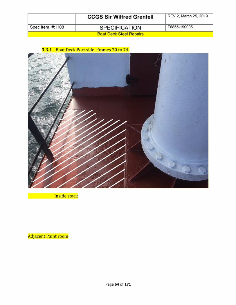
CCGS Sir Wilfred Grenfell REV 2, March 25, 2019
Spec Item #: H08 SPECIFICATION F6855-190005
Boat Deck Steel Repairs
Page 64 of 171
3.3.1 Boat Deck Port side. Frames 70 to 74.
Inside stack
Adjacent Paint room

CCGS Sir Wilfred Grenfell REV 2, March 25, 2019
Spec Item #: H08 SPECIFICATION F6855-190005
Boat Deck Steel Repairs
Page 65 of 171
Part 4: PROOF OF PERFORMANCE: 4.1 Weld Inspection and Testing 4.1.1 The Contractor shall perform tests to verify that all requirements of the
Specification are met. 4.1.2 The steel work is to be completed to the satisfaction of the attending TCMS
Inspector and Chief Engineer. The completed steel work is to be visually inspected after welding is completed.
4.1.3 There is to be a 10% MPI testing completed on the deck welds by approved testing
personnel. 4.1.4 This testing is to be carried out in the presence of the attending TCMS surveyor and
owner’s representative. All costs associated with the inspection to be included in the contractor’s price for known steel work. The contractor is to be responsible to contact Transport Canada for all inspections.
4.1.5 The contractor is responsible for all air quality testing to ensure hot work and entry
is permitted. The contractor shall issue and post hot work permits and shall maintain a fire watch.
4.1.6 After acceptance of the test on the weld seams by the TCMS and owner’s
representatives, the area is to be inspected to ensure all debris has been removed. 4.1.7 After acceptance of the steel work, the contractor may commence to reinstall
insulation and outfit. .
4.3 Certification

CCGS Sir Wilfred Grenfell REV 2, March 25, 2019
Spec Item #: H08 SPECIFICATION F6855-190005
Boat Deck Steel Repairs
Page 66 of 171
4.3.1 Welding procedure will be as per Preamble.
Part 5: Deliverables:
5.1 Drawings/Reports
5.1.1 All reports from the work specified shall be given to the Chief Engineer.
5.2 Spares
5.2.1 N/A
5.3 Training
5.3.1 N/A
5.4 Manuals
5.4.1 N/A

April 3rd, 2019 – May 8th, 2019
CCGS Sir Wilfred Grenfell REV 2, March 25, 2019
Spec Item – H09 SPECIFICATION F6855-190005
Port Outboard Main Engine Clutch Overhaul Inspection/Cleaning
Page 67 of 171
H-09 Port Outboard Main Engine Clutch Overhaul Inspection/Cleaning - REMOVED

CCGS Sir Wilfred Grenfell REV 2, March 25, 2019
Spec Item – H10 SPECIFICATION F6855-190005
Stbd Inboard Main Engine Clutch Survey
Page 68 of 171
H-10 Stbd Inboard Main Engine Clutch Survey Part 1: Scope:
1.1 The intent of this item shall be open up the clutch for its 5 year survey by TCMS. The contractor shall supply the services of FSR to oversee the work stated below and provide a final report. All work shall be performed by the contractor unless otherwise stated below.
1.2 The Contractor shall arrange for the services of Pneumaflex Clutch Service Engineers for the overhaul.
Part 2: References:
2.1 Guidance Drawings/Nameplate Data
2.1.1 Clutch data: Lohmann+Stolterfoht
Type: Pneumaflex KA
Model: KAA 220
Mass: 1180 KG
All fasteners and piping are metric.
2.2 Standards
2.2.1 Ships ISM Hot-Work, Confined Space, Fall Protection Lockout Procedures
2.3 Regulations
2.3.1 N/A
2.4 Owner Furnished Equipment
2.4.1 The contractor shall supply all materials, Parts, equipment, labor and Tools required to perform the specified work.
Part 3: Technical Description:
3.1 General

CCGS Sir Wilfred Grenfell REV 2, March 25, 2019
Spec Item – H10 SPECIFICATION F6855-190005
Stbd Inboard Main Engine Clutch Survey
Page 69 of 171
3.1.1 The Contractor shall supply all equipment, staging, chain falls, cranage, slings and shackles necessary to perform the work. All lifting equipment shall be appropriate for the expected duties, and be accompanied by current certification indicating, or be permanently marked as to being, of an adequate safe working load for the expected duties. Any brackets or other welded attachments required in the performance of this specification shall be welded into place by CWB-certified welders certified to welding Std. W47.1, Div. 1 and 2). Proof of certification must be provided to the Chief Engineer prior to commencement of steel work. Prior to any hot work taking place the Contractor shall ensure the area of work is gas freed suitable for hot work and the appropriate gas free certificates issued and placed as per the requirements of CCG Fleet Safety Manual.
3.1.2 The Contractor shall isolate and lockout both main engines associated with this clutch, lockout are to be entered into the ships lockout record book and lockouts shall be removed and entered into lockout book after completion of repairs.
3.1.3 Contractor shall bid on providing assistance to FSR for the duration of the overhaul if required by FSR.
3.1.3.1 Contractor shall quote on having FSR onsite for 4 working days at 8 hrs per day (32 hrs total) and 2 travel days at 8 hrs per day(16 hrs total).
3.1.1.2 Contractor shall quote on providing 64 hours of assistance as required by FSR to be adjusted up/down by PWGSC 1379 as required.
Pre Removal
3.1.3 The contractor shall remove the clutch guard surrounding the clutch as well as any necessary piping, wiring, etc to facilitate the removal of the clutch assembly.
3.1.4 The FSR shall measure and record the clutch drum travel in the ahead and astern positions as per the manufacturers’ specifications.
3.1.5 Copies of the 3.1.4 readings shall be given to the Chief Engineer prior to continuing removal of the clutch.

CCGS Sir Wilfred Grenfell REV 2, March 25, 2019
Spec Item – H10 SPECIFICATION F6855-190005
Stbd Inboard Main Engine Clutch Survey
Page 70 of 171
3.1.6 The FSR shall ensure that all faces of the associated flanges and spacer plates are properly "proof" marked for subsequent re-assembly and correct orientation.
Removal and Disassembly
3.1.7 The contractor with the assistance from the FSR, shall remove the clutch to the FSR facilities for disassembly if required. Disassembly, cleaning, inspection and re-assembly shall be performed by the FSR.
3.1.8 The contractor shall be aware of the central feed line and seal ring before removal.
3.1.9 The attending Transport Canada Marine Safety Surveyor and Chief Engineer shall inspect the clutch components before re-assembly.
3.1.10 The contractor shall be responsible for arranging the attendance of the TCMS Surveyor.
Re-Installation and Testing
3.1.11 The contractor shall transport the clutch assembly back to the ship and with the assistance of the FSR, re-install it in good order ensuring correct orientation of associated flanges and spacer rings using the proof marks. All proof mark locations shall be verified. All fasteners shall be properly torqued.
3.1.12 The contractor shall advise the Chief Engineer when the clutch is ready to be tested.
3.1.13 The ship’s crew will manually operate the clutch to check for correct operation and air leaks after installation with the contractor’s personnel in attendance.
3.1.14 The FSR shall record the clutch travel readings and present them to the Chief Engineer at this time.
3.1.15 The contractor shall replace all guards, disturbed piping, wiring, and other removals in good order on completion of the above work.
3.2 Interferences
3.2.1 N/A

CCGS Sir Wilfred Grenfell REV 2, March 25, 2019
Spec Item – H10 SPECIFICATION F6855-190005
Stbd Inboard Main Engine Clutch Survey
Page 71 of 171
3.3 Location
3.3.1 Stbd Inboard Main Engine
Part 4: Proof of Performance
4.1 Inspection
4.1.1 All work and materials used shall be to satisfaction of Chief Engineer.
4.2 Testing
4.2.1 Upon completion of all work, the clutch shall be tested for correct operation with the engine running to the satisfaction of the Chief Engineer. This will include a load or sea trial at the Chief Engineer’s discretion.
4.3 Certification
4.3.1 N/A
Part 5: Deliverables:
5.1 Drawings/Reports
5.1.1 Following completion of the above work to the satisfaction of the attending TCMS Surveyor, Chief Engineer a receipt of three typewritten copies of all the measurements and readings are required in the FSR report, as well as an Electronic Copy of the report.
5.2 Spares
5.2.1 N/A
5.3 Training
5.3.1 N/A
5.4 Manuals
5.4.1 N/A

CCGS Sir Wilfred Grenfell REV 2, March 25, 2019
Spec Item – H11 SPECIFICATION F6855-190005
Port Fuel Oil Purifier Replacement
Page 72 of 171
H-11 Port Fuel Oil Purifier Replacement – Updated From Bidders Conference Part 1: Scope:
1.1 The intent of this item shall be to remove existing purifier and replace with new GSM supplied direct replacement purifier.
1.2 The Contractor shall arrange for the manufacturer’s field technician to supervise the work.
1.2.1 Alfa Laval FSR with training/experience with purifier operation required for 2 days to complete start-ups, testing and trials upon completion of installation.
Part 2: References:
2.1 Guidance Drawings/Nameplate Data
2.1.1 MOPX 205 F/O Separator
2.2 Standards
2.2.1 Canadian Coast Guard Fleet Safety Manual (DFO 5737)
2.2.2 Coast Guard ISM Confined Space Entry 7.D.9
2.2.3 Ships ISM Lockout, Hotwork, Fall Prevention, Confined Space Entry, permits are required to be completed for commencement of work.
2.3 Regulations
2.3.1 CSA Marine Machinery Regulations.
2.4 Owner Furnished Equipment
2.4.1 Owner shall supply new F/O Purifier unit.
2.4.2 The contractor shall supply all other materials, equipment, labour and tools that are required to perform the specified work.
Part 3: Technical Description:

CCGS Sir Wilfred Grenfell REV 2, March 25, 2019
Spec Item – H11 SPECIFICATION F6855-190005
Port Fuel Oil Purifier Replacement
Page 73 of 171
3.1 General
3.1.1 The Contractor shall supply all equipment, staging, chain falls, cranage, slings and shackles necessary to perform the work. All lifting equipment shall be appropriate for the expected duties, and be accompanied by current certification indicating, or be permanently marked as to being, of an adequate safe working load for the expected duties. Any brackets or other welded attachments required in the performance of this specification shall be welded into place by CWB-certified welders certified to welding Std. W47.1, Div. 1 and 2). Proof of certification must be provided to both the Chief Engineer prior to commencement of steel work. Prior to any hot work taking place the Contractor shall ensure the area of work is gas freed suitable for hot work and the appropriate gas free certificates issued and posted as per the requirements of CCG Fleet Safety Manual.
3.1.2 The Contractor shall disconnect all fluid connections to and from existing purifier and properly cap all pipes to prevent ingress of contaminants.
3.1.3 The Contractor shall disconnect all electrical connections to the purifier.
3.1.4 The contractor shall arrange for the removal of purifier from its seats and place in a suitable location onboard as determined by Chief Eng.
3.1.5 The ships crew shall have new purifier unit onboard vessel prior to vessel arriving at dry-dock.
3.1.6 The contractor shall sling new purifier into place on the existing seats and secure in place under the direction of FSR.
3.1.7 The contractor shall remove caps from all fluid connections and reconnect to new purifier.
3.1.8 The contractor shall reconnect electrical connections to purifier.
3.1.9 The purifier shall be commissioned and run for a period of 24 hours under the direction/supervision of the FSR and Chief Engineer.
3.2 Location
3.2.1 Engine Room

CCGS Sir Wilfred Grenfell REV 2, March 25, 2019
Spec Item – H11 SPECIFICATION F6855-190005
Port Fuel Oil Purifier Replacement
Page 74 of 171
3.3 Interferences
3.3.1 The Contractor shall be responsible for the identification of all interference items, their temporary removal, storage and refitting to vessel.
Part 4: Proof of Performance
4.1 Inspection
4.1.1 All work shall be completed to the satisfaction of the Alfa Laval FSR, TCMS Surveyor and the Chief Engineer.
4.2 Testing
4.2.1 A 24 hour run test of the purifier shall be performed under direction of FSR and Chief Engineer.
4.3 Certification
4.3.1 N/A
Part 5: Deliverables:
5.1 Drawings/Reports
5.1.1 N/A
5.2 Spares
5.2.1 N/A
5.3 Training
5.3.1 N/A
5.4 Manuals
5.4.1 N/A

CCGS Sir Wilfred Grenfell REV 2, March 25, 2019
Spec Item: H12 SPECIFICATION F6855-190005
Door Repairs Hydraulic Machinery Space
Page 75 of 171
H-12 Door Repairs in Hydraulic Machinery Space – Updated from Bidders Conference Part 1: Scope:
1.1 The intent of this specification shall be to remove the Weathertight door from the Hydraulic Machinery Space on the Wheelhouse Top, repair and re-install.
1.2 This work is to be completed in conjunction with replacement of the Natural Vent for the Hydraulic Machinery Space on the Wheelhouse Top.
Part 2: REFERENCES:
2.1 Guidance Drawings/Nameplate Data
2.1.1 N/A
2.2 Standards
2.2.1 Ships ISM Hot-Work, and Lockout Procedures. The contractor will be responsible for completion of the lockout / tag out log sheets. The contractor is to demonstrate how the lockout / tag out procedure meet the requirements before work begins. For audit purposes the completed lockout / tag out log and hot work sheets are to be delivered to the Chief Engineer when completed.
2.3 Regulations
2.3.1 CSA Fire regulations
2.4 Owner Furnished Equipment
2.4.1 The contractor shall supply all materials, equipment, and parts required to perform the specified work unless otherwise stated.
Part 3: Technical Description:

CCGS Sir Wilfred Grenfell REV 2, March 25, 2019
Spec Item: H12 SPECIFICATION F6855-190005
Door Repairs Hydraulic Machinery Space
Page 76 of 171
3.1 General
3.1.1 The systems associated with this particular space shall be locked out and tagged out in consultation with the Chief Engineer.
3.1.2 The contractor shall remove the Weathertight Door from the Hydraulic Machinery Space on Wheelhouse Top and transport to their facility for repairs. The Contractor shall allow for 2 crane lifts to remove door from the vessel and return.
3.1.3 The Contractor shall use a temporary covering to close off the entrance to the
Hydraulic Machinery Space to protect the inside from the weather or water ingress.
3.1.4 The Contractor shall grit blast the entire door (both sides) including the track
for the seal. (SSPC-SP6 Profile). 3.1.5 The Contractor shall crop out the corroded section of the Weathertight Door
in the area of the door seal and insert new metal. Approximately 0.5M2. 3.1.6 The Contractor shall remove the “Door Latch” mechanism from the door and
insert metal to fill in the holes to make the door weathertight.

CCGS Sir Wilfred Grenfell REV 2, March 25, 2019
Spec Item: H12 SPECIFICATION F6855-190005
Door Repairs Hydraulic Machinery Space
Page 77 of 171
3.1.7 The Contractor will inspect the Weathertight Door “Dogs” for freedom of movement and wear.
3.1.8 The contractor will apply 2 coats of International Intershield 300 primer and 2 top coats of International Interthane 990 White to the entire door (both sides). Substitutes may be accepted in consultation with the Chief Engineer.
3.1.9 The Contractor shall inspect the Hinge Pins of the door and replace where required. Any repairs will be actioned by 1379.
3.1.10 Coast Guard shall supply new gasket material and contractor shall cut and install. Upon re-installation of the door they are to ensure proper fit and adjust the securing dogs so that all are in contact with the wedges. A “Hose Test” is to be used to verify the integrity of the seal. Freshwater is to be used with a minimum of 50psi.
CCGS Sir Wilfred Grenfell REV 2, March 25, 2019
Spec Item: H12 SPECIFICATION F6855-190005
Door Repairs Hydraulic Machinery Space
Page 78 of 171
3.1.21 The Contractor shall fabricate and install a drip edge over the top edge of the door. Dimensions: 4” Drip Edge, 40” wide, fabricated from 1/8” plate. This will be welded the entire width of the drip edge to seal to bulkhead.
3.2 Interferences 3.2.1 The Contractor is responsible for identification of interference items (this
shall include but is not limited to panels and insulation for access to fire watch), their temporary removal, storage, and refitting to the vessel.
Part 4: Proof of Performance
4.1 Inspection
4.1.1 All work shall be completed to the satisfaction of the Chief Engineer.
4.2 Testing
4.2.1 The Hose test shall be completed using fresh water of no less than 50psi.
4.3 Certification
4.3.1 N/A
Part 5: Deliverables:
5.1 Drawings/Reports
5.1.1 N/A
5.2 Spares
5.2.1 N/A
5.3 Training
5.3.1 N/A
5.4 Manuals

CCGS Sir Wilfred Grenfell REV 2, March 25, 2019
Spec Item: H12 SPECIFICATION F6855-190005
Door Repairs Hydraulic Machinery Space
Page 79 of 171
5.4.1 N/A
Inside of door to Hydraulic Machinery Space
on Wheelhouse Top.

CCGS Sir Wilfred Grenfell REV 2, March 25, 2019
Spec Item: H12 SPECIFICATION F6855-190005
Door Repairs Hydraulic Machinery Space
Page 80 of 171
Outside of door to Hydraulic Machinery Space
on Wheelhouse Top.

CCGS Sir Wilfred Grenfell REV 2, March 25, 2019
Spec Item: H13 SPECIFICATION F6855-190005
Miscellaneous Pipe Work
Page 81 of 171
New for Bidder Conference: Section 3.1.12 Scupper Pipe Replacement Auxiliary Machinery Room
H-13 Miscellaneous Pipe Work and Repairs – Updated for Bidders Conference Part 1: Scope:
1.1 The intent of this specification shall be to have all the listed piping replaced with new. All renewed piping will be hot dipped galvanized except where specified.
Part 2: REFERENCES:
2.1 Guidance Drawings/Nameplate Data
2.1.2 N/A
2.2 Standards
2.2.1 Ships ISM Hot-Work, and Lockout Procedures. The contractor will be responsible for completion of the lockout / tag out log sheets. The contractor is to demonstrate how the lockout / tag out procedure meet the requirements before work begins. For audit purposes the completed lockout / tag out log and hot work sheets are to be delivered to the Chief Engineer when completed.
2.3 Regulations
2.3.1 CSA Fire regulations
2.4 Owner Furnished Equipment:
2.4.1 The contractor shall supply all materials, equipment, and parts required to perform the specified work unless otherwise stated.
Part 3: Technical Description:
3.1 General

CCGS Sir Wilfred Grenfell REV 2, March 25, 2019
Spec Item: H13 SPECIFICATION F6855-190005
Miscellaneous Pipe Work
Page 82 of 171
3.1.1 The systems associated with these particular pipes shall be locked out and tagged out in consultation with the Chief Engineer.
3.1.2 The contractor shall remove and renew all listed piping, complete with flanges, bulk head fittings and Roustabouts. The renewed pipes shall be hot dipped galvanized and then reinstalled using new stainless steel bolts and nuts. The gaskets shall be replaced with contractor supplied as fitted gaskets. All welds shall be TCMS approved for its location and purpose.
3.1.3 Any new or disturbed steel or piping is to be given a coat of primer upon
completion of work followed by a top coat of as per existing paint scheme. 3.1.4 Natural Vent Pipe Hydraulic Machinery Space located Wheelhouse Top:
3.1.4.1 The contractor shall remove the mesh covering and insulation (approximately 1M2) from the inside of the Hydraulic Machinery Space in order to provide for safe hot work around the Natural Vent. The mesh and new insulation to be re-installed after work is completed.

CCGS Sir Wilfred Grenfell REV 2, March 25, 2019
Spec Item: H13 SPECIFICATION F6855-190005
Miscellaneous Pipe Work
Page 83 of 171
3.1.4.2 The Contractor shall crop out the existing corroded 3” Natural Vent (c/w cover) and replace with new material of equal specifications. (Sch 40 black iron pipe).
3.1.4.3 The Contractor shall fabricate and install a new cover with securing mechanism so that the vent can be closed.
3.1.4.4 The Contractor shall apply 2 coats of Primer and 2 coats of White Top Coat to all disturbed areas. This is to include the inside of the Natural Vent as well.
3.1.5 Auxiliary Seawater Cooling Pump #2 Suction Line:
3.1.5.1 The Contractor is to remove the 7” section of 2.5” suction pipe c/w flanges and replace with new galvanized pipe (Sch 40) c/w new flanges and gaskets. All fasteners are to be replaced with new and threads protected coated for protection. New gaskets are to be supplied and installed. Outside diameter of flange is 7.65”. (4 bolt flange). Flanges are to be welded to the pipe and fit tested prior to hot dip galvanizing.

CCGS Sir Wilfred Grenfell REV 2, March 25, 2019
Spec Item: H13 SPECIFICATION F6855-190005
Miscellaneous Pipe Work
Page 84 of 171
3.1.6 S/S Seabay Suction Lines:
3.1.6.1 The Contractor shall remove each existing 3 foot section of 2 ½”, schedule 40, suction line, roustabouts, butterfly valves and strainer baskets. A new section of said pipe, c/w flange, shall be fabricated to fit new owner-supplied strainer basket. Said pipe sections are to be hot dipped galvanized when complete. Contractor shall supply two new 2 ½” butterfly valves and roustabouts to fit both port and Stb arrangements. All fasteners and gaskets are to be replaced with new and threads protected coated for protection.
3.1.7 FiFi Seabay Vent Line
3.1.7.1Contractor shall remove and replace with new, a vent line in ER that penetrates the exterior deck to a goose neck vent. This line consists two sections of 2 ½” schedule 40 pipe. Lower ER section flanged at one end, welded deck coupling at other end. Above deck section is a goose neck vent to welded deck coupling. Total piping length is 15 feet.
3.1.8 Navigation Light Boxes

CCGS Sir Wilfred Grenfell REV 2, March 25, 2019
Spec Item: H13 SPECIFICATION F6855-190005
Miscellaneous Pipe Work
Page 85 of 171
3.1.8.1The Contractor shall remove and replace as original, 2 Navigation Lighting Boxes. This consists of 2 open sided rectangular boxes mounted to the ship side railing to which the Port and Stb Navigation Lights are mounted in. Each box measures 48” in length; 22” high; 9.5” wide; ¼” thick. Contractor to install wiring glands in box for said lights.
3.1.9 Exterior Stairs
3.1.9.1 Contractor shall remove each section of stairs and fabricate new sections as per original and install. Each stair section is 20ft10in in Length and rises to a height of 16ft 3in. The width of the stairway is 28.5in and consists of 22 stair treads (44 total).Each stairway has handrails with stanchions on both sides welded to stair frame and surrounding bulkheads. The upper railing and stanchions consists of 60ft of 1 ¼” schedule 40 pipe (120ft total) and the lower railing consists of 45ft of 1” schedule 40 pipe (90ft total). Each stairway is attached to the superstructure at top and bottom by welding. Each of the stair treads are to be

CCGS Sir Wilfred Grenfell REV 2, March 25, 2019
Spec Item: H13 SPECIFICATION F6855-190005
Miscellaneous Pipe Work
Page 86 of 171
bolted to the framework to allow for easy replacement. Only one Stairway is to be removed at a time to allow access to Bridge Deck. Openings created by the removal of the Stairs are to be made safe to the satisfaction of the Chief Engineer.
3.1.10 Sheathing Underside of Bridge Wing
3.1.10.1Contractor shall remove existing section of sheathing from the underside of the Bridge Wing and replace it with new. Contractor shall replace any damaged insulation enclosed in that section with new. Contractor shall bid on replacing The section consists of 1/16” galvanized sheet metal attached with stainless steel screws. Contractor shall bid on replacing 3m2 of sheet metal and 3m2 of Rockwool insulation. Access to this area will require rigging of scaffolding.
3.1.11 Repair Exhaust Leak POME
Contractor to replace the gasket in a 24” exhaust flange in the exhaust piping for the POME. This gasket to be Contractor supplied and heat rated equivalent to one removed. Contractor is responsible for repairs to the metal shielding and insulation underneath. New nuts and bolts to be installed upon completion.

CCGS Sir Wilfred Grenfell REV 2, March 25, 2019
Spec Item: H13 SPECIFICATION F6855-190005
Miscellaneous Pipe Work
Page 87 of 171
3.1.12 Scupper pipe replacement auxiliary machinery room.
The existing pipe to be renewed consists of 11 feet of 2 ½ inch pipe flanged at both ends. There is also a roust-about joining this pipe. The pipe also has a 2 inch pipe teed into it and a 1 ½ inch pipe teed into it. The pipe is schedule 40 pipe.
Contractor shall remove the existing pipe via the flanges. The 2 inch section and the 1 ½ inch section shall be separated at 1 foot from the 2 ½ inch pipe. These will have to be cut out. The contractor shall fabricate a new section of pipe to fit. The new pipe shall have a flange in the place of the existing roust about and pipe unions fitted on the 2 inch section and the 1 ½ inch sections as joiners. The new pipe shall be hot dipped galvanized and schedule 40 steel pipe. See the below pictures of the existing pipe. As this pipe is in use on the ship the contractor shall inform the Chief Engineer prior to removal. This pipe is located in the forward machinery space.

CCGS Sir Wilfred Grenfell REV 2, March 25, 2019
Spec Item: H13 SPECIFICATION F6855-190005
Miscellaneous Pipe Work
Page 88 of 171
Above are pictures of the section of scupper pipe to be replaced.
3.2 Location

CCGS Sir Wilfred Grenfell REV 2, March 25, 2019
Spec Item: H13 SPECIFICATION F6855-190005
Miscellaneous Pipe Work
Page 89 of 171
3.2.1. FiFi Seabay vent line – lower section is in Upper ER Level, port side. Upper section is on Fwd Tow Deck, Port side.
3.2.2. Navigation Light Boxes – Located Port and Stb Sides on Lower Bridge Deck.
3.2.3. Exterior Stairs – Port and Stb sides, exterior Focsle to Bridge Decks.
3.2.4. Sheathing on Bridge Wing – Lower Bridge Deck, stb side.
3.3 Interferences
3.3.1 The Contractor is responsible for identification of interference items.
Part 4: Proof of Performance
4.1 Inspection
4.1.1. All work shall be completed to the satisfaction of the Chief Engineer. 4.1.2. The pipes shall be pressure tested to 100 PSI prior to installation.
4.2 Testing
4.2.1 The systems are to be operationally tested in consultation with the Chief Engineer.
4.3 Certification
4.3.1 N/A
Part 5: Deliverables:
5.1 Drawings/Reports
5.1.1 N/A
5.2 Spares
5.2.1 N/A

CCGS Sir Wilfred Grenfell REV 2, March 25, 2019
Spec Item: H13 SPECIFICATION F6855-190005
Miscellaneous Pipe Work
Page 90 of 171
5.3 Training
5.3.1 N/A
5.4 Manuals
5.4.1 N/A

CCGS Sir Wilfred Grenfell REV 2, March 25, 2019
Spec Item: H14 SPECIFICATION F6855-190005
Warping Head Repairs
Page 91 of 171
H-14 Warping Head Repairs Part 1: Scope:
1.1 The intent of this specification shall be for the contractor to make repairs to the warping head as listed below.
Part 2: References:
2.1 Guidance Drawings/Nameplate Data
2.1.1 N/A
2.2 Standards
2.2.1 N/A
2.3 Regulations
2.3.1 CSA Marine Machinery Regulations
2.4 Owner Furnished Equipment
2.4.1 The contractor shall supply all materials, equipment, and parts required to perform the specified work unless otherwise stated.
Part 3: Technical Description:
3.1 General
3.1.1 Contractor shall remove port warping head from windlass.
3.1.2 Contractor shall follow the below repair procedure from Rolls Royce.

CCGS Sir Wilfred Grenfell REV 2, March 25, 2019
Spec Item: H14 SPECIFICATION F6855-190005
Warping Head Repairs
Page 92 of 171
3.1.3
Contractor shall reinstall the warping head on winch as per original install.
3.1.4 Contractor shall notify Transport Canada prior to starting any weld repairs to allow for a viewing of warping head.
3.2 Location
3.2.1 N/A
3.3 Interferences
3.3.1 Contractor is responsible for the identification of interference items, their temporary removal, storage and refitting to vessel.
Part 4: Proof of Performance
4.1 Inspection
4.1.1 All work shall be completed to the satisfaction of the Chief Engineer.
4.2 Testing
4.2.1 N/A
4.3 Certification
4.3.1 N/A

CCGS Sir Wilfred Grenfell REV 2, March 25, 2019
Spec Item: H14 SPECIFICATION F6855-190005
Warping Head Repairs
Page 93 of 171
Part 5: Deliverables:
5.1 Drawings/Reports
5.1.1 All reports from the work specified shall be given to the Chief Engineer.
5.2 Spares
5.2.1 N/A
5.3 Training
5.3.1 N/A
5.4 Manuals
5.4.1 N/A

CCGS Sir Wilfred Grenfell REV 2, March 25, 2019
Spec Item: H15 SPECIFICATION F6855-190005
Fuel Oil Tank Cleaning and Inspection
Page 94 of 171
New for Bidders Conference: Remove #14 Fuel Tank from Cleaning and Inspection
H-15 Fuel Oil Tank Cleaning and Inspection – Updated for Bidders Conference Part 1: Scope:
1.1 The intent of this item shall be to clean, inspect and pressure test the following tanks for TCMS survey.
1.2 This work shall be carried out in conjunction with the following:
1.2.1 HD-05 Waste Oil Tank Steel Remediation
Part 2: References:
2.1 Guidance Drawings/Nameplate Data
TANK LOCATION CAPACITY m³ TCMS #
#11 Port Fuel FR. 62-82 104.7 3L021
#11 Stbd Fuel FR 62-82 104.7 3L020
Part 3: Technical Description:
3.1 Ship’s personnel shall pump/drain the tanks to suction level.
3.2 The contractor shall dispose of any remaining fuel or sludge ashore. Quote on removal of 1000 litres per tank; to be adjusted up or down as required by 1379.
3.3 Tanks shall be certified gas free and safe for men to enter, by a certified chemist. One copy of each gas free certificate shall be posted outside of subject tank, near manhole, and one copy of each certificate shall be given to the Chief Engineer prior to men entering the tank. Each tank interior is then to be washed with high pressure water/degreaser mixture, and remnants disposed of. Tanks are then to be wiped dry.

CCGS Sir Wilfred Grenfell REV 2, March 25, 2019
Spec Item: H15 SPECIFICATION F6855-190005
Fuel Oil Tank Cleaning and Inspection
Page 95 of 171
3.4 Tank internals are then to be inspected by the Chief Engineer and attending TCMS Surveyor.
3.5 Tank vent heads shall be removed (one per tank) to prepare for an air test using a manometer on each tank. Each tank shall then be air tested to the satisfaction of attending TCMS surveyor.
3.6 Upon completion each tank shall be drained and internals wiped dry. Owner’s representative shall inspect each tank prior to final closing. Vent pipe valve bodies shall be replaced using new gaskets. Manhole covers and docking plugs shall be replaced as per original using new ¼” BUNA N rubber gaskets on manholes.
3.7 The contractor shall supply all material to perform the specified work
Part 4: Proof of Performance
4.1 Inspection
4.1.1 All work shall be completed to the satisfaction of the Chief Engineer.
4.2 Testing
4.2.1 Each tank shall then be air tested to the satisfaction of attending TCMS surveyor
4.3 Certification
4.3.1 The contractor shall obtain and provide documentation to the Chief Engineer all required technical certification as specified in the applicable rules and codes.
4.3.2 Equipment and component inspection certificates including all test reports supporting the certifications shall be given to the Chief Engineer.
Part 5: Deliverables:
5.1 Drawings/Reports
5.1.1 Equipment and component inspection certificates including all test reports supporting the certifications shall be given to the Chief Engineer.
5.2 Spares

CCGS Sir Wilfred Grenfell REV 2, March 25, 2019
Spec Item: H15 SPECIFICATION F6855-190005
Fuel Oil Tank Cleaning and Inspection
Page 96 of 171
5.2.1 N/A
5.3 Training
5.3.1 N/A
5.4 Manuals
5.4.1 N/A
CCGS Sir Wilfred Grenfell REV 2, March 25, 2019
Spec Item – H16 SPECIFICATION F6855-190005
Port and Stbd Gearbox Oil Cooler Cleaning and Inspection
Page 97 of 171
H-16 Port and Stbd Gearbox Oil Cooler Cleaning and Inspection Part 1: Scope: 1.1 The intent of this specification shall be to open up both gearbox oil coolers for cleaning,
inspection and survey to satisfy the requirements of TCMS.
Part 2: References:
2.1 Guidance Drawings/Nameplate Data
2.1.1 Gear Oil cooler data
2.1.1.1 Type OKS 5/31
2.2 Standards
2.2.1 National Institute of Standards Technology
2.3 Regulations
2.3.1 CSA Marine Machinery Regulations
2.4 Owner Furnished Equipment
2.4.1 The contractor shall supply all materials, equipment, labor and parts required to perform the specified work unless otherwise stated.
Part 3: Technical Description:
3.1 General
3.1.1 The Contractor shall ensure that the gearbox oil coolers are completely drained and that all gearbox oil pumps are isolated and locked out and recorded in the vessels’ lockout book.
3.1.2 Coolers shall be disassembled, thoroughly cleaned, reassembled and pressure tested. Pressures shall be set as noted in the nameplate section of this item.
3.1.3 The end covers shall have replaced new gaskets where applicable.
3.2 Location
3.2.1 Engine Room Tank Top aft

CCGS Sir Wilfred Grenfell REV 2, March 25, 2019
Spec Item – H16 SPECIFICATION F6855-190005
Port and Stbd Gearbox Oil Cooler Cleaning and Inspection
Page 98 of 171
3.3 Interferences
3.3.1 The Contractor shall be responsible for the identification of all interference items, their temporary removal, storage and refitting to vessel.
Part 4: Proof of Performance
4.1 Inspection
4.1.1 All work shall be completed to the satisfaction of the Chief Engineer and TCMS.
4.2 Testing
4.2.1 All coolers shall be tested for leaks after installation when the gear oil system is put back in service.
4.3 Certification
4.3.1 N/A
Part 5: Deliverables:
5.1 Drawings/Reports
5.1.1 All reports from the work specified shall be given to the Chief Engineer.
5.2 Spares
5.2.1 N/A
5.3 Training
5.3.1 N/A
5.4 Manuals
5.4.1 N/A

CCGS Sir Wilfred Grenfell REV 2, March 25, 2019
Spec Item: H17 SPECIFICATION F6855-190005
Fish Plate Renewal
Page 99 of 171
H-17 Fish Plate Renewal Part 1: Scope:
1.1 The intent of this item shall be for the contractor to take shots on Stbd Side of deck fish plate near FRC Davit
Part 2: References:
2.1 Guidance Drawings/Nameplate Data
2.1.1
2.2 Standards
2.2.1 Ships ISM Hot-Work, Confined Space, Fall Protection Lockout Procedures

CCGS Sir Wilfred Grenfell REV 2, March 25, 2019
Spec Item: H17 SPECIFICATION F6855-190005
Fish Plate Renewal
Page 100 of 171
2.3 Regulations
2.3.1 N/A
2.4 Owner Furnished Equipment
2.4.1 The contractor shall supply all materials, Parts, equipment, labor and Tools required to perform the specified work.
Part 3: Technical Description:
3.1 General
3.1.1 The Contractor shall supply all equipment, staging, chain falls, cranage, slings and shackles necessary to perform the work. All lifting equipment shall be appropriate for the expected duties, and be accompanied by current certification indicating, or be permanently marked as to being, of an adequate safe working load for the expected duties. Any brackets or other welded attachments required in the performance of this specification shall be welded into place by CWB-certified welders certified to welding Std. W47.1, Div. 1 and 2). Proof of certification must be provided to the Chief Engineer prior to commencement of steel work. Prior to any hot work taking place the Contractor shall ensure the area of work is gas freed suitable for hot work and the appropriate gas free certificates issued and placed as per the requirements of CCG Fleet Safety Manual.
3.1.2 The Contractor shall mechanically remove rust and paint from approx. 2.5m x 0.5m of fishplate and quote on 100 UT shots to be taken.
3.1.3 The Contractor shall provide a detailed report outlining the scope of work for necessary repairs. The report shall include an estimate of the labor and materials to complete the repairs. Any temporary repairs will be actioned by 1379.
3.1.4 Contractor shall provide a price per m2 of existing steel plate removed, new plate supplied and installed, adjusted by 1379. Unless otherwise approved, all new steel to be mill certified Grade 44W in accordance with CAN/CSA G40.21.6. NDT shall be covered by 1379 upon proof of invoice.

CCGS Sir Wilfred Grenfell REV 2, March 25, 2019
Spec Item: H17 SPECIFICATION F6855-190005
Fish Plate Renewal
Page 101 of 171
3.1.5 Contractor shall recoat any disturbed paint (approx. 1 M2) with the following:
3.1.4.1 Primer: Apply two touch up coats of Amercoat 5105 Primer to all bare areas. Apply @ 2 to 3 mils DFT
3.1.4.2 Topcoat: Apply two full coats of Amercoat 5450 Topcoat to entire primed area. Apply @ 2 to 3 mils DFT. Color Coast Guard Red (509-102).
3.1.6 Interference items in this area are minimal as it is located in the engine room escape hatch area with no insulation removal required.
3.2 Interferences
3.2.1 N/A
3.3 Location
3.3.1 Stbd Inboard Main Engine Room
Part 4: Proof of Performance
4.1 Inspection
4.1.1 All work and materials used shall be to satisfaction of Chief Engineer.
4.2 Testing
4.2.1 N/A
4.3 Certification
4.3.1 N/A
Part 5: Deliverables:
5.1 Drawings/Reports
5.1.1 Following completion of the above work to the satisfaction of the attending TCMS Surveyor, Chief Engineer a receipt of three typewritten copies of all the measurements and readings as well as an Electronic Copy of the report.

CCGS Sir Wilfred Grenfell REV 2, March 25, 2019
Spec Item: H17 SPECIFICATION F6855-190005
Fish Plate Renewal
Page 102 of 171
5.2 Spares
5.2.1 N/A
5.3 Training
5.3.1 N/A
5.4 Manuals
5.4.1 N/A

CCGS Sir Wilfred Grenfell REV 2, March 25, 2019
Spec Item: H18 SPECIFICATION F6855-190005
FRC Cradle Inspection
Page 103 of 171
H-18 FRC Cradle Part 1: Scope:
1.1 The intent of this specification shall be to Grit Blast the FRC Cradles, inspect the welds, and re-coat.
1.2 This work is to be completed in a temperature controlled environment.
Part 2: References:
2.1 Guidance Drawings/Nameplate Data:
2.1.1 N/A
2.2 Standards:
2.2.1 Ships ISM Hot-Work, and Lockout Procedures. The contractor will be responsible for completion of the lockout / tag out log sheets. The contractor is to demonstrate how the lockout / tag out procedure meet the requirements before work begins. For audit purposes the completed lockout / tag out log and hot work sheets are to be delivered to the Chief Engineer when completed.
2.3 Regulations
2.3.1 CG regulations for Lifting Appliances.
2.4 Owner Furnished Equipment:
2.4.1 The contractor shall supply all materials, equipment, and parts required to perform the specified work unless otherwise stated.
Part 3: Technical Description:
3.1 General
3.1.1 The systems associated with this particular space shall be locked out and tagged out in consultation with the Chief Engineer.

CCGS Sir Wilfred Grenfell REV 2, March 25, 2019
Spec Item: H18 SPECIFICATION F6855-190005
FRC Cradle Inspection
Page 104 of 171
3.1.2 The vessels crew shall lower the Port & Stbd FRC Cradles to the dock, disconnect the cables, and remove sheaves and rollers.
3.1.3 The Contractor shall transport the 2 FRC Cradles to their facility to be grit blasted
clean. (SSPC SP 6)
3.1.4 The Contractor shall perform MPI testing to all the welds and report any deficiencies. Repairs will be actioned under 1379.
3.1.5 Once the welds have been passed, the cradles shall be placed in a controlled
environment and prepared for recoating. 3.1.6 The cradles shall be given two coats of International 300 Epoxy Primer and two top
coats of International Interthane 990 White.
3.1.7 The Contractor will transport the Cradles back to the vessel where the Crew will re-attach and secure.
3.2 Interferences 3.2.1 The Contractor is responsible for identification of interference items. If the
cradles cannot be lowered to the dock, then the Contractor will supply 4 lifts of the Yards crane to remove and re-install the 2 cradles.
Part 4: Proof of Performance
4.1 Inspection
4.1.3. All work shall be completed to the satisfaction of the Chief Engineer.
4.2 Testing
4.2.1 Contractor responsible for MPI testing.
4.3 Certification
4.3.1 MPI will be completed by a qualified person, certified in MPI testing.
Part 5: Deliverables:
5.1 Drawings/Reports
5.1.1 N/A

CCGS Sir Wilfred Grenfell REV 2, March 25, 2019
Spec Item: H18 SPECIFICATION F6855-190005
FRC Cradle Inspection
Page 105 of 171
5.2 Spares
5.2.1 N/A
5.3 Training
5.3.1 N/A
5.4 Manuals
5.4.1 N/A

CCGS Sir Wilfred Grenfell REV 2, March 25, 2019
Spec Item – H19 SPECIFICATION F6855-190005
Sure Climb System Install
Page 106 of 171
H-19 Install Sure Climb System on Main Mast – Updated From Bidders Conference Part 1: SCOPE
1.1 The intent of this spec is to have a Vertical Lifeline Cable System installed on the Main Mast of the vessel.
Part 2: REFERENCES
2.1 Guidance Drawings/Nameplate Data
2.1.1 MSA SureClimb Vertical Lifeline Cable System – Part No. SFPLS 353050
2.1.2 MSA SureClimb Cable Grab – Part No. 10040010
2.2 Standards
2.2.1 Canadian Coast Guard Fleet Safety Manual (DFO 5737)
2.3 Regulations
2.3.1 CSA Marine Machinery Regulations.
2.4 Owner Furnished Equipment
2.4.1 MSA SureClimb Vertical Lifeline Cable System. Part No. SFPLS 353050
MSA SureClimb Cable Grab. Part No. 10040010
2.4.2 The contractor shall supply all other materials, parts, equipment, tools and labor that are required to perform the specified work.
2.4.3 The Contractor will allow for two lifts of their crane for this work.
Part 3 : Technical Description:
3.1 General
3.1.1 The Contractor shall install the SureClimb Vertical Lifeline Cable System as per the Manufacturer’s instructions and have the System certified.

CCGS Sir Wilfred Grenfell REV 2, March 25, 2019
Spec Item – H19 SPECIFICATION F6855-190005
Sure Climb System Install
Page 107 of 171
3.1.2 The Contractor shall arrange for an MSA trained installer or an experienced installer to oversee the install and certify the system when completed. Experience shall be considered as 2 previous lifeline installs.
3.1.3 Manufacturer’s Details
3.2 Interferences

CCGS Sir Wilfred Grenfell REV 2, March 25, 2019
Spec Item – H19 SPECIFICATION F6855-190005
Sure Climb System Install
Page 108 of 171
3.2.1 The Contractor is responsible for identification of interference items (this shall include but is not limited to panels and insulation for access to fire watch), their temporary removal, storage, and refitting to the vessel.
Part 4: Proof of Performance
4.1 Inspection
4.1.1 All work shall be completed to the satisfaction of the Chief Engineer.
4.2 Testing
4.2.1 In accordance with Transport Canada Regulations, Coast Guard Regulations and Provincial Regulations.
4.3 Certification
4.3.1 Certificate to be provided.
Part 5: Deliverables:
5.1 Drawings/Reports
5.1.1 N/A
5.2 Spares
5.2.1 N/A
5.3 Training
5.3.1 N/A
5.4 Manuals
5.4.1 N/A

CCGS Sir Wilfred Grenfell REV 2, March 25, 2019
Spec Item – H20 SPECIFICATION F6855-190005
Hydro Blast Port and Stbd Anchor Chains
Page 109 of 171
H-20 Hydro Blast Port and Stbd Anchor Chains – Updated From Bidders Conference Part 1: Scope
1.1 The intent of this specification shall be for the contractor to High Pressure Water Blast the Port & Stbd Anchor Chains, inspect & paint the chain.
Part 2: REFERENCES
2.1 Guidance Drawings/Nameplate Data:
2.1.1 N/A
2.2 Standards:
2.2.1 Ships ISM Hot-Work, and Lockout Procedures. The contractor will be responsible for completion of the lockout / tag out log sheets. The contractor is to demonstrate how the lockout / tag out procedure meet the requirements before work begins. For audit purposes the completed lockout / tag out log and hot work sheets are to be delivered to the Chief Engineer when completed.
2.3 Regulations
2.3.1 CSA Fire regulations
2.4 Owner Furnished Equipment:
2.4.1 The contractor shall supply all materials, equipment, and parts required to perform the specified work unless otherwise stated.
Part 3: Technical Description
3.1 General
3.1.1 The systems associated with this particular space shall be locked out and tagged out in consultation with the Chief Engineer.

CCGS Sir Wilfred Grenfell REV 2, March 25, 2019
Spec Item – H20 SPECIFICATION F6855-190005
Hydro Blast Port and Stbd Anchor Chains
Page 110 of 171
3.1.2 The Vessels Crew will lower the Port and Stbd Anchors to the dock with the assistance of the Contractor.
3.1.3 The Contractor shall “flake” the chain on the dock so that it can be accessed
for inspection and cleaning. The Chain will be lowered to its maximum length without releasing the “Bitter Ends”.
3.1.3.1 Contractor shall ensure that chain is flaked out on an area free of debris, blasting grit prior to coating.
3.1.4 The Anchor Chains will be secured by way of the vessels equipment so that
the load is off the Windlass and the Chains are safely secured to the satisfaction of the Contractor and Chief Engineer.
3.1.5 The Contractor shall high pressure water blast the Port & Stbd Anchor Chains to remove dirt & scale to allow for inspection and recoating by contractor.
3.1.6 Contractor shall allow for 15 UT Shots per side taken at random links.
3.1.6 The Contractor shall release the Port & Stbd Anchors from the chains at the Anchor Shackles and install new (owner supplied) Anchor Shackles.
3.1.7 Upon completion of the recoating, the Contractor shall assist the Crew to hoist the Anchors and Chains back onboard the vessel and secure.
3.1.7.1 Contractor shall apply 1 coat of Amercoat 238 white to both chains at 1 shot intervals starting at from connection to anchor.
3.1.8 The Contractor shall allow for 2 lifts of the Contractors crane to remove any kinks or twists in the chain.
3.2 Interferences 3.2.1 N/A
Part 4: Proof of Performance
4.1 Inspection
4.1.1 All work shall be completed to the satisfaction of the Chief Engineer.
4.2 Testing

CCGS Sir Wilfred Grenfell REV 2, March 25, 2019
Spec Item – H20 SPECIFICATION F6855-190005
Hydro Blast Port and Stbd Anchor Chains
Page 111 of 171
4.2.1 N/A
4.3 Certification
4.3.1 N/A
Part 5: Deliverables
5.1 Drawings/Reports
5.1.1 N/A
5.2 Spares
5.2.1 N/A
5.3 Training
5.3.1 N/A
5.4 Manuals
5.4.1 N/A

CCGS Sir Wilfred Grenfell REV 2, March 25, 2019
Spec Item – H21 SPECIFICATION F6855-190005
Escape Hatch Replacement
Page 112 of 171
H-21 Escape Hatch Replacement - Removed

CCGS Sir Wilfred Grenfell REV 2, March 25, 2019
Spec Item – H22 SPECIFICATION F6855-190005
Interior Door Replacement
Page 113 of 171
H-22 Interior Door Replacement Part 1: SCOPE:
1.1 To replace 3 existing Interior Fire doors as listed with owner supplied new ones.
1.2 The Doors to be replaced are as follows;
1.2.1 Hospital exit to Port alleyway, Main Deck. (B0)
1.2.2 Stair Tower entrance, Stairs to Laundry Room. (A60)
1.2.3 Crossway Door outside Laundry Rm. (A60)
Part 2: REFERENCES:
2.1 Drawings
2.1.1 Joiner Systems Drawings
2.2 Standards
2.2.1 Ships ISM Hot-Work, Confined Space, Fall Protection and Lockout Procedures. The contractor will be responsible for completion of the lockout / tag out log sheets. The contractor is to demonstrate how the lockout / tag out procedure meet the requirements before work begins. For audit purposes the completed lockout / tag out log sheets are to be delivered to the Chief Engineer when completed.
2.3 Regulations
2.3.1 CSA Fire Regulations
2.4 Owner Furnished Equipment
2.4.1 The contractor shall supply all materials, equipment, parts and labor required to perform the specified work unless otherwise stated.
Part 3: TECHNICAL DESCRIPTION:
3.1 General
Removal of existing Doors:

CCGS Sir Wilfred Grenfell REV 2, March 25, 2019
Spec Item – H22 SPECIFICATION F6855-190005
Interior Door Replacement
Page 114 of 171
3.1.1 All insulation, Ceiling and Bulkhead paneling in the affected area to be removed as required for new door installations. Paneling /trim to be stored for re-installation when work is completed.
3.1.2 The adjacent spaces to be protected with fire retardant cloth and fire-proof covering placed on the interior deck covering where applicable. A fire watch is to be maintained at all times during hot work.
3.2.3 The contractor shall erect barriers to protect the surrounding areas from smoke and dirt. Lighting and ventilation to be maintained within the confines of the barriers.
3.2.4 The contractor will be responsible for erecting, moving, reassembling and disassembling the barriers as the work progresses to a new area.
3.1.5 Existing doors are to be cropped according to specified Opening requirements in supplied drawings. The Contractor shall consult TCMS on the crop and weld procedure prior to commencing this work.
3.1.6 Contractor to remove old doors from the vessel and dispose of in an approved manner.
3.2 New Door Installations:
3.2.1 The welds shall be 100 % NDT tested for integrity and a copy of the report given to the Chief Engineer. The welds shall be coated internally and externally as per coating of that particular area. The NDT method shall be ultrasonic testing.
3.2.2 All cropped edges shall be ground clean.
3.2.3 New doors are to be installed as per Manufacturer’s procedure and as directed by the attending TCMS Inspector.
3.2.4 Integrity and fitting to be completed to the satisfaction of the attending TCMS Inspector.
3.2.5 The complete area, new steel and heat effected steel is then to be coated with one complete coat of primer. This process is to ensure that all steel in the repair area is completely primed.
3.2.6 After priming, any and all bulkheads that are not covered by paneling are to have two coats of latex interior paint. The coating is to match the current surrounding bulkhead paint type and color
3.2.7 Applicable areas around the interior of doors to be re-insulated with new material and trim and paneling re-installed as per original.

CCGS Sir Wilfred Grenfell REV 2, March 25, 2019
Spec Item – H22 SPECIFICATION F6855-190005
Interior Door Replacement
Page 115 of 171
3.3 Interferences
3.3.1 The Contractor is responsible for identification of interference items, their temporary removal, storage, and refitting to the vessel.
3.3.2 For the door stated in 1.2.123 “Laundry Rm Crossway” the Contractor shall relocate the existing FM200 bottle and associated piping from the Fwd side to aft side of door. Contractor to obtain the services of a qualified Fire Systems Tech to assist with relocation.
Part 4: PROOF OF PERFORMANCE:
4.1 Weld Inspection and Testing
4.1.1 The Contractor shall perform tests to verify that all requirements of the Specification are met.
4.1.2 The steel work is to be completed to the satisfaction of the attending TCMS Inspector and Chief Engineer. The completed steel work is to be visually inspected after welding is completed.
4.1.3 There is to be a 100% MPI testing completed on the welds by approved testing personnel.
4.1.4 The contractor is responsible to contact Transport Canada for all inspections and testing.
4.1.5 The contractor is responsible for all air quality testing to ensure hot work and entry is permitted. The contractor shall issue and post hot work permits and shall maintain a fire watch.
4.1.6 After acceptance of the test on the weld seams by the TCMS and owner’s representatives, the area is to be inspected to ensure all debris has been removed.
4.1.7 After acceptance of the steel work, the contractor may commence to reinstall insulation and outfit.
4.2 Certification:
4.2.1 The Contractor shall obtain and provide to the Technical Authority all required technical Certifications as specified in the applicable rules and codes in accordance with Standards.
Part 5: Deliverables

CCGS Sir Wilfred Grenfell REV 2, March 25, 2019
Spec Item – H22 SPECIFICATION F6855-190005
Interior Door Replacement
Page 116 of 171
5.1 Drawings/Reports
5.1.1 Following completion of the above work to the satisfaction of the attending TCMS Surveyor, Chief Engineer a receipt of three typewritten copies of all the measurements and readings are required.
5.2 Spares
5.2.1 N/A
5.3 Training
5.3.1 N/A
5.4 Manuals
5.4.1 N/A
CCGS Sir Wilfred Grenfell REV 2, March 25, 2019
Spec Item – H23 SPECIFICATION F6855-190005
Foc’sle Deck Drain Replacement
Page 117 of 171
H-23 Foc’sle Deck Drain Replacement – Updated From Bidders Conference Part 1: Scope:
1.1 The intent of this spec is to have the Foc’sle Deck Scupper Drain from the Foc’sle Deck to the Main Deck Replaced.
Part 2: References:
2.1 Guidance Drawings/Nameplate Data
2.1.1 Reference Drawing: Scuppers & Drains Diagram (37-04239R) Sheets 1 and 2.
2.2 Standards
2.2.1 Ships ISM Hot-Work, Confined Space, Fall Protection Lockout Procedures
2.3 Regulations
2.3.1 N/A
2.4 Owner Furnished Equipment
2.4.1 The contractor shall supply all materials, Parts, equipment, labor and Tools required to perform the specified work.
Part 3: Technical Description:
3.1 General
3.1.1 The Contractor shall remove and dispose of the existing corroded Scupper Drain from the Foc’sle Deck STBD transiting the SAR Locker (internally) and terminating on the Main Deck STBD.
3.1.2 The Contractor shall fabricate and install a new Scupper Drain using 2” X 16ft Sch.80 pipe. Reference drawing 37-04239R (Sheet 2) Detail “D”.
3.1.3 Due to interference items in SAR locker. Contractor shall reroute new scupper drain through aft SAR locker bulkhead approximately 1 ft down from deckhead to outside. Scupper shall penetrate exterior deck and connect
CCGS Sir Wilfred Grenfell REV 2, March 25, 2019
Spec Item – H23 SPECIFICATION F6855-190005
Foc’sle Deck Drain Replacement
Page 118 of 171
to existing drain below. Existing penetration in SAR locker deck shall be sealed by welding a blank in the existing deck drain.
3.1.4 Contractor shall perform Dye Penetrant testing on 100% of new welds.
3.1.3 The Contractor shall be responsible for removal & Re-installation of insulation and other interferences inside the SAR Locker.
3.1.4 Contractor shall recoat any disturbed paint (approx. 1 M2) with the following:
3.1.4.1Primer: Apply two coats of Amercoat 5105 Primer to all bare areas. Apply @ 2 to 3 mils DFT
3.1.4.2Topcoat: Apply two full coats of Amercoat 5450 White Topcoat to entire primed area. Apply @ 2 to 3 mils.
3.2 Interferences
3.2.1 SAR Locker insulation & sheeting.
3.2.2 #9 Stbd Fuel Oil Tank Vent Pipe.
3.3 Location
3.3.1 The Foc’sle Deck Stbd Scupper Drain is located on the Foc’sle Deck Stbd (Fr. 63-64) and transits through the SAR Locker (Stbd Main Deck) and terminates on the main Deck. Reference Drawing 37-04239R (Sheet 1) Item 11.
Part 4: Proof of Performance
4.1 Inspection
4.1.1 All work and materials used shall be to satisfaction of Chief Engineer.
4.2 Testing
4.2.1 N/A
4.3 Certification
4.3.1 N/A

CCGS Sir Wilfred Grenfell REV 2, March 25, 2019
Spec Item – H23 SPECIFICATION F6855-190005
Foc’sle Deck Drain Replacement
Page 119 of 171
Part 5: Deliverables:
5.1 Drawings/Reports
5.1.1 Following completion of the above work
5.2 Spares
5.2.1 N/A
5.3 Training
5.3.1 N/A
5.4 Manuals
5.4.1 N/A

CCGS Sir Wilfred Grenfell REV 2, March 25, 2019
Spec Item: H24 SPECIFICATION F6855-190005
Female Washroom Deck Refurbishment
Page 120 of 171
H-24 Female Washroom Deck Refurbishment – Updated From Bidders Conference Part 1: SCOPE:
1.1 Replace the deck material in the Female Washroom with a Seamless Deck Epoxy System. Measure deck plate thickness and repair if necessary.
Part 2: REFERENCES:
2.1 Guidance Drawings/Nameplate Data
2.1.1 Drawing: Scuppers & Drains Diagram # 37-04239 Sh. 1 of 2
2.1.2 General Arrangement NJC-10-100
2.2 Standards
2.2.1 Canadian Coast Guard Fleet Safety Manual (DFO 5737)
2.2.2 Coast Guard ISM Confined Space Entry 7.D.9
2.2.3 ISM hot work, Confined Space entry, and fall protection procedures are to be strictly enforced.
2.2.4 All welding shall be as per specification preamble.
2.2.5 CG Lockout Procedure.
2.3 Regulations
2.3.1 All deck covering materials shall be non-combustible, approved by TCMS for its intended usage, and shall comply with the requirements of hull construction Regulations – Part X “Fire protection for cargo ships of 500 Tons Gross Tonnage or more” Method 1C.
2.4 Owner Furnished Equipment
2.4.1 The contractor shall supply all materials, equipment, labor and parts required to preform the specified work unless otherwise stated.
CCGS Sir Wilfred Grenfell REV 2, March 25, 2019
Spec Item: H24 SPECIFICATION F6855-190005
Female Washroom Deck Refurbishment
Page 121 of 171
Part 3: TECHNICAL DESCRIPTION:
3.1 General
Existing Configuration:
3.1.1 The washroom is equipped with two toilet and shower stalls and double sink vanity. The total deck area is 96 square feet. (This includes the area under the shower stall). Thickness of current underlayment is ½”.
3.2 Deck
3.2.1 The Contractor shall remove all the ceramic tile flooring from the deck of the washroom including the raised combing around the perimeter of the washroom. The surface shall be cleaned of all grout, Dex-O-Tex, and cement to bare metal. This work shall be completed between the hours of 0700 and 1900 hours.
3.2.2 In preparation for ultrasonic shots and the application of new deck paint covering, the areas of steel deck plating, bottom section of bulkhead, that were exposed by the deck covering, shall be thoroughly cleaned free of scale, rust, glue, high spots and debris.
3.2.3 The contractor shall have an ultrasonic NDT technician take 12 ultrasonic shots on the exposed steel to establish the amount of deck plating if any to be replaced. The Chief Engineer in consultation with the NDT technician will decide the best locations for the ultrasonic shots. Before testing, the Contractor shall at each identified test location grind the surface coating to bare metal while ensuring that any dishing of the metal is prevented. Contractor shall prepare and supply a report on the findings and amount of plating to be replaced to Chief Engineer immediately after the testing is complete. This Survey report shall include the metal thickness measurements; and diagram(s) of the deck showing the test points and plating, if any to be replaced. This NDT survey shall be completed within seven day after the start of refit to allow for time for steel replacement if necessary.
3.2.4 Before any more remedial work on this item is commenced; Chief engineer shall invite TCMS Hull inspector to inspect the deck to ascertain if additional

CCGS Sir Wilfred Grenfell REV 2, March 25, 2019
Spec Item: H24 SPECIFICATION F6855-190005
Female Washroom Deck Refurbishment
Page 122 of 171
testing/repairs are required and so that proper notes for future vessel hull surveys can be made. Contractor shall also quote on unit cost per additional ultrasonic shot and shall be adjusted up or down by PWGSC 1379 action.
3.2.5 The Contractor shall crop out, dispose of and replace any deteriorated deck plating as determined by TCMS. The new plating must also have the proper mill certification; copy of same shall be given to Chief Engineer and TCMS inspectors.
3.2.6 The Contractor shall bid on replacing 5 Square feet of 3/8 inch deck plating in the Wash room. Contractor shall also quote on unit price per square foot of deck plate replacement. Deck Plating required shall be adjusted up or down by PWGSC 1379 action.
3.2.7 After completion of steel deck repairs, the complete new and old steel deck plating, bottom section of bulkheads, that were originally under the old cement, shall be coated in accordance with manufacturers’ specifications in preparation of the Seamless Epoxy Floor System.
3.2.8 The contractor shall install a Seamless Epoxy deck system in accordance with manufacturers’ specifications.
3.3 Shower Stalls
3.3.1 The stall deck will be incorporated in the new Seamless Floor system and shower linings replaced with Contractor supplied stainless steel sheeting.
3.3.2 The Contractor shall replace the shower drain scuppers with new.
3.4 Sinks and Mirrors
3.4.1 The Contractor shall disconnect and remove existing sink, mirror, light fixture and backing board.
3.4.2 When deck work is completed, all piping and drain connection shall re-oriented to fit and re-connected.
3.4.3 The Contractor shall install new Owner supplied Vanity, sink and mirror.
3.5 Toilets

CCGS Sir Wilfred Grenfell REV 2, March 25, 2019
Spec Item: H24 SPECIFICATION F6855-190005
Female Washroom Deck Refurbishment
Page 123 of 171
3.5.1 The two toilets shall be removed and re-installed when deck work is completed. The deck shall be cleaned to bare metal. This shall be done prior to taking ultrasonic shots. New toilet securing studs shall be stainless steel. The toilets shall be installed on the Teflon pad; some minor rework of ABS pipe in the toilet area may be required.
3.6 Location
3.6.1 Main Deck
3.7 Interferences
3.7.1 The Contractor shall be responsible for the identification of all interference items, their temporary removal, and storage and refitting to vessel.
3.7.2 The affected areas under washroom will be Laundry Room and stairway landing.
Part 4: PROOF OF PERFORMANCE:
4.1 Inspection
4.1.1 All work shall be completed to the satisfaction of the Chief Engineer and TCMS.
4.2 Testing
4.2.1 N/A
4.3 Certification
4.3.1 All welding shall be as per specification preamble.
Part 5: DELIVERABLES:
5.1 Drawings/Reports
5.1.1 The Contractor shall prepare and supply a report on the ultrasonic shots. This Survey report shall include the metal thickness measurements; and diagram(s) of the deck showing the test points and plating, if any, to be replaced.
5.1.2 All reports from the work specified shall be given to the Chief Engineer.
5.2 Spares

CCGS Sir Wilfred Grenfell REV 2, March 25, 2019
Spec Item: H24 SPECIFICATION F6855-190005
Female Washroom Deck Refurbishment
Page 124 of 171
5.2.1 N/A
5.3 Training
5.3.1 N/A
5.4 Manuals
5.4.1 N/A

CCGS Sir Wilfred Grenfell REV 2, March 25, 2019
Spec Item: H25 SPECIFICATION F6855-190005
2nd Cook and Boat Deck Alley Covering Replacement
Page 125 of 171
H-25 2nd Cook and Boat Deck Alley Covering Replacement – Updated From Bidders Conference Part 1: SCOPE:
1.1 The intent of this specification shall be to replace the deck Underlayment and vinyl covering, clean steel deck to near white metal, and inspect and test the condition of the steel deck. Replace steel deck where wastage is beyond acceptable limits to the below noted deck areas.
1.2 The locations and areas of deck are as follows;
1.2.1 2nd Cook Cabin – 70 ft2.
1.2.2 Alleyway Boat deck –175 xft2.
1.3 REMOVED
1.4 This work shall be carried out in Conjunction with:
1.4.1 H-24 Female Washroom Refurbishments
Part 2: REFERENCES:
2.1 Guidance Drawings/Nameplate Data
2.1.1 # 37-109-R Insulation Plan
2.1.2 # 37-113-R Deck Coverings,
2.1.3 H57 Joiner Bulkheads and linings,
2.1.4 H60 insulation Plan, and H64 Deck Coverings
2.2 Standards
2.2.1 Lloyd’s register Rules and Regulations for the Classification of Ships
2.2.2 Ships ISM Lockout/ Hotwork/ Confined Space Entry Procedures.
2.2.3 All deck covering and underlayment materials shall be non-combustible, approved by TCMS for its intended usage, and shall comply with the

CCGS Sir Wilfred Grenfell REV 2, March 25, 2019
Spec Item: H25 SPECIFICATION F6855-190005
2nd Cook and Boat Deck Alley Covering Replacement
Page 126 of 171
requirements of hull construction regulations – Part X “Fire protection for cargo ships of 500 Tons Gross Tonnage or more” Method 1C.
2.3 Regulations
2.3.1 All materials shall be approved by TCMS for its intended usage, and shall comply with the requirements of Hull Construction Regulations.
2.4 Owner Furnished Equipment
2.4.1 The contractor shall supply all materials, equipment, labor and parts required to perform the specified work unless otherwise stated.
Part 3: TECHNICAL DESCRIPTION:
Note: Work on this Item shall be completed between 0700 and 2000 hours as there will be a crew sleeping on board night times.
3.1 General
3.1.1 Contractor shall install temporary dust curtains around the perimeter of work area, sufficient to prevent contamination of adjacent bulkheads, decks, and equipment, with dust and residues produced as a result of the work.
3.1.2 2nd Cook Cabin
3.1.3 Prior to commencement of restoration work the Contractor shall remove any interference items attached to the deck. The cabins contain a settee, locker, sink/vanity and bunk.
3.1.4 Contractor shall remove any Joiner bulkhead and deckhead paneling in areas mentioned in 1.1 that are required to complete the work. All paneling shall be re-installed with the exception of ones designated by the Chief Engineer. The bulkhead paneling shall be re-covered with owner-supplied Givslad Foil covering as directed by the manufacturer. This covering shall be done by a qualified coverings installation Technician.
3.1.5 The Contractor shall ensure the safe off site storage of furniture, ceiling and bulkhead paneling from the cabin being worked on. The Contractor shall be responsible for any damage that occurs to said items for the duration of the work.
CCGS Sir Wilfred Grenfell REV 2, March 25, 2019
Spec Item: H25 SPECIFICATION F6855-190005
2nd Cook and Boat Deck Alley Covering Replacement
Page 127 of 171
3.1.6 On completion of work, contractor shall ensure all areas/equipment affected by the work to be cleaned of dust and residues.
3.1.7 The contractor shall remove 70 ft2 of vinyl flooring in total and underlay from the deck in the area.
3.1.8 Boat Deck Alleyway Port and Starboard sides.
3.1.9 The Contractor shall remove the vinyl deck covering from the entirety of the alleyway (175sq ft) keeping the underlay intact except for area defined in 3.1.10.
3.1.10 The Contractor shall only remove underlay starting at Stbd side, aft end forward 40 feet (100sq ft total). Contractor shall quote a unit cost for underlayment removal to be adjusted by PWGSC 1379 action upon completion. Contractor to complete UT Testing to determine the extent of any steel replacement. The direction of such replacement is to be determined by the attending TCMS Inspector.
3.1.11 In preparation for the new flooring, Steel bulkhead areas exposed by the removal work, the entire steel deck in the areas listed in Section 1.2 shall be Power Tooled Cleaned To Bare Metal SSPC-SP.
3.1.12 Contractor to obtain services of (NDT) Technician to complete UT as directed by the attending TCMS Inspector and the Chief Engineer.
3.1.13 Contractor to allow for 75 UT shots on areas of steel deck showing corrosion and quote cost per shot. Extra to be adjusted up or down by PWGSC 1379 action. This NDT survey shall be completed within seven day after the start of refit to allow for time for steel replacement if necessary.
Contractor to allow for 25 square feet of 9mm thick main deck steel to be replaced. Contractor shall also quote on unit price per square foot of deck plate replacement. Deck Plating required shall be adjusted up or down by PWGSC 1379 action.
3.1.14 The whole of the steel deck in the areas listed in Section 1.2 are to be painted with 2 coats of Amercoat 83HS epoxy primer following paint manufacturer application procedures, and time required between Coats.

CCGS Sir Wilfred Grenfell REV 2, March 25, 2019
Spec Item: H25 SPECIFICATION F6855-190005
2nd Cook and Boat Deck Alley Covering Replacement
Page 128 of 171
3.1.15 If new deck plating is to be installed it must be installed in accordance with good marine practice with attention paid to proper plate corner radius, the new plating if any and the complete area of the exposed steel deck shall be thoroughly cleaned free of scale, rust, and debris.
3.1.16 Before testing, Contractor shall at each identified test location grind the surface coating to bare metal while ensuring that any dishing of the metal is prevented. Contractor shall prepare and supply a report on the findings and amount of plating to be replaced to Chief Engineer immediately after the testing is complete. This Survey Report shall include the metal thickness measurements; and diagram(s) of the deck showing the test points and plating, if any to be replaced.
3.1.17 Before any more remedial work on this item is commenced; Chief engineer shall invite TCMS Hull inspector to inspect the deck to ascertain if planned remedial work is sufficient.
3.1.18 Contractor shall crop out, dispose of and replace any deteriorated deck plating (as determined by TCMS Inspector, with new plating in accordance with good marine practice and attention paid to proper plate corner radius and minimum plate sizes, this is important.
3.1.19 After installation of any steel deck inserts Contractor shall have a NDT technician to do MPI test on the welding.
3.2 New Underlayment and coverings Scheme:
3.2.1 The Contractor shall install TCMS approved Underlayment over the areas at a thickness specified by the manufacturer. Thickness of current underlayment is 1/2”.
3.2.2 The Contractor shall install new TCMS approved Deck covering over the entirety of the areas.
3.2.3 Installation and sealing of vinyl decking shall be completed by professional installer.
3.2.4 After completion of repairs, all the items that were removed are to be re-installed and secured in their original positions with the exception of items identified by the Chief Engineer to be replaced with owner-supplied new.

CCGS Sir Wilfred Grenfell REV 2, March 25, 2019
Spec Item: H25 SPECIFICATION F6855-190005
2nd Cook and Boat Deck Alley Covering Replacement
Page 129 of 171
3.2.5 Contractor shall cover the existing Joiner Panels with Owner supplied Givslad Foil on each panel as directed by the Chief Engineer. Contractor to quote cost per panel for bidding purposes as follows
3.2.5.1 2nd Cook Cabin – 18 panels.
3.2.5.2 Boat Deck Alleyway – 44 panels.
3.2.6 A four inch vinyl border shall be applied to all furniture, bulkheads, equipment, and cabinetry.
3.3 Location
3.3.1 Work areas are on Main Deck and Boat deck.
3.4 Interferences
3.4.1 Removals as specified in work description.
3.4.2 Below deck is the Crews’ Lounge, Focsle Deck Alleyway and Fwd Machinery Space.
3.4.3 Contractor is responsible for identification of interference items, their temporary removal, storage, and refitting to the vessel.
Part 4: PROOF OF PERFORMANCE:
4.1 Inspection
4.1.1 All work shall be completed to the satisfaction of the Chief Engineer and TCMS Inspector.
4.2 Testing
4.2.1 Contractor shall perform MPI test on all welding of new plate. Copies of reports shall be given to the Chief Engineer.
4.3 Certification
4.3.1 New steel material test certificates shall be given to the Chief engineer.
4.3.2 Classification and/or Transport Canada Approval Certificates of underlayment and vinyl floor covering for Marine use shall be given to the

CCGS Sir Wilfred Grenfell REV 2, March 25, 2019
Spec Item: H25 SPECIFICATION F6855-190005
2nd Cook and Boat Deck Alley Covering Replacement
Page 130 of 171
Chief Engineer.
4.3.3 Welding Certification as per Specification Preamble.
Part 5: DELIVERABLES:
5.1 Drawings/Reports
5.1.1 All reports from the work specified shall be given to the Chief Engineer
5.2 Spares
5.2.1 N/A
5.3 Training
5.3.1 N/A
5.4 Manuals
5.4.1 N/A

CCGS Sir Wilfred Grenfell REV 2, March 25, 2019
Spec Item – H26 SPECIFICATION F6855-190005
Washrooms Refurbishment
Page 131 of 171
H-26 Washroom Refurbishments Part 1: SCOPE:
1.1 The intent of this specification is to outline the work required in refurbishing the following washrooms;
1.1 2nd Engineer’s Cabin.
1.2 2nd Mate Cabin.
1.3 3rd Mate Cabin
1.2 To assess the extent of steel replacement necessary and to plan and schedule this replacement, deck coverings shall be removed from affected areas and ultrasonic testing performed within 5-days of contract commencement.
1.3 This work shall be carried out in Conjunction with the following:
Part 2: REFERENCES:
2.1 Guidance Drawings/Nameplate Data
2.1.1 Drawing: Scuppers & Drains Diagram # 37-04239 Sh. 1 of 2
2.1.2 General Arrangement NJC-10-100
2.2 Standards
2.2.1 Canadian Coast Guard Fleet Safety Manual (DFO 5737)
2.2.2 Coast Guard ISM Confined Space Entry 7.D.9
2.2.3 ISM hot work, Confined Space entry, and fall protection procedures are to be strictly enforced.
2.2.4 All welding shall be as per specification preamble.
2.2.5 CG Lockout Procedure.
2.3 Regulations

CCGS Sir Wilfred Grenfell REV 2, March 25, 2019
Spec Item – H26 SPECIFICATION F6855-190005
Washrooms Refurbishment
Page 132 of 171
2.3.1 All deck covering materials shall be non-combustible, approved by TCMS for its intended usage, and shall comply with the requirements of hull construction Regulations – Part X “Fire protection for cargo ships of 500 Tons Gross Tonnage or more” Method 1C.
2.4 Owner Furnished Equipment
2.4.1 The contractor shall supply all materials, equipment, labor and parts required to complete the specified work unless otherwise stated.
Part 3: TECHNICAL DESCRIPTION:
3.1 General
Existing Configuration:
3.1.1 Each of the washrooms are equipped with one toilet and shower stall, one vanity with sink and mirror. The total deck area of each washroom is approximately 22 square feet.
3.2 Deck
3.2.1 The Contractor shall remove all the ceramic tile flooring from the deck of the washroom including the raised combing around the perimeter of the washroom. The existing wash room tiles are on the deck, and go up the perimeter of the lower section of the bulkheads, and are a distance of 4 inches from the deck forming a border or a ceramic tile baseboard. The surface shall be cleaned of all grout, Dex-O-Tex, and cement to bare metal.
3.2.2 In preparation for ultrasonic shots and the application of new deck paint covering, the areas of steel deck plating, bottom section of bulkhead, that were exposed by the deck covering, shall be thoroughly cleaned free of scale, rust, glue, high spots, and debris.
3.2.3. The contractor shall have an ultrasonic NDT technician take 12 ultrasonic shots per washroom on the exposed steel to establish the amount of deck plating if any to be replaced. The Chief Engineer in consultation with the NDT technician will decide the best locations for the ultrasonic shots. Before testing, the Contractor shall at each identified test location grind the surface coating to bare metal while ensuring that any dishing of the metal is

CCGS Sir Wilfred Grenfell REV 2, March 25, 2019
Spec Item – H26 SPECIFICATION F6855-190005
Washrooms Refurbishment
Page 133 of 171
prevented. Contractor shall prepare and supply a report on the findings and amount of plating to be replaced to Chief Engineer immediately after the testing is complete. This Survey report shall include the metal thickness measurements; and diagram(s) of the deck showing the test points and plating, if any to be replaced.
3.2.4. Before any more remedial work on this item is commenced; the contractor shall invite TCMS Hull inspector to inspect the deck to ascertain if additional testing/repairs are required and so that proper notes for future vessel hull surveys can be made. Contractor shall also quote on unit cost per additional ultrasonic shot and shall be adjusted up or down by PWGSC 1379 action.
3.2.5. The Contractor shall crop out, dispose of and replace any deteriorated deck plating (as determined by Chief Engineer, with new plating in accordance with good marine practice with attention paid to minimum plate amounts, proper plate corner radius etc. The new plating must also have the proper mill certification; copy of same shall be given to Chief Engineer and TCMS inspectors.
3.2.6. The Contractor shall bid on replacing 5 Square feet of 3/8 inch deck plating per washroom. Contractor shall also quote on unit price per square foot of deck plate replacement. Deck Plating required shall be adjusted up or down by PWGSC 1379 action.
3.2.7. After completion of steel deck repairs, the complete new and old steel deck plating, bottom section of bulkheads, which were originally under the old cement, shall be coated in accordance with manufacturers’ specifications in preparation of the Seamless Epoxy Floor System.
3.2.8. The contractor shall install a Seamless Epoxy deck system in accordance with manufacturers’ specifications.
3.3 Shower Stall
3.3.1 Shower stall insert and its base shall be removed and a new base incorporated into the seamless flooring system. (Completed with a 4 inch high perimeter)

CCGS Sir Wilfred Grenfell REV 2, March 25, 2019
Spec Item – H26 SPECIFICATION F6855-190005
Washrooms Refurbishment
Page 134 of 171
3.3.2 Contractor shall remove Joiner panels as necessary to permit removal of flooring. These panels will be re-used when work is complete. New tracking to remount panels will be needed.
Contractor shall remove deckhead paneling in Washroom. New owner-supplied panels shall be installed.
3.3.3 The Contractor shall install stainless steel sheeting on the 2 bulkheads of each the 3 shower stalls. This is approximately 36 square feet of stainless sheeting per stall. This shall include a 3 inch lip on the two bulk head corners of the shower stall the full height of the stall just outside of the curtain rods. (to prevent water splashing out around the curtain). A stainless steel enclosure is to cover piping and mixing shower valve. This is to be completed by a qualified sheet-metal tradesperson.
3.3.4 A new Contractor-supplied shower curtain rail shall be installed.
3.4 Sink and mirror
3.4.1 The Contractor shall disconnect and remove existing sink, vanity, mirror, light fixture and backing board in each washroom. These will be re-used.
3.4.2 All piping and drain connections shall be re-oriented to fit and re-connected.
3.4.3 The contractor shall reinstall owner supplied vanity, sink and mirror. The Contractor shall hook up the sink after it is installed with owner supplied fittings.
3.5 Toilet
3.5.1 The toilet shall be removed from the seating, toilet shall be reused. The deck underneath shall be cleaned to bare metal. This shall be done prior to taking ultrasonic shots. New toilet securing studs shall be stainless steel. The toilet shall be installed on a Teflon pad (Contractor supplied); some minor rework of ABS pipe in the toilet area may be required.
3.5.2 All work and materials shall be to the satisfaction of Chief Engineer.
3.5.3 The Contractor shall dispose of the removals to the Contractor’s facilities.

CCGS Sir Wilfred Grenfell REV 2, March 25, 2019
Spec Item – H26 SPECIFICATION F6855-190005
Washrooms Refurbishment
Page 135 of 171
3.6 Location
3.6.1 2nd Engineer’s Cabin, Boat Deck, Port side.
2nd Mate Cabin, Boat Deck, Port Side.
3rd Mate Cabin, Boat Deck, Port Side.
3.7 Interferences
3.7.1 The Contractor shall be responsible for the identification of all interference items and their temporary removal, storage and refitting to vessel.
Part 4: PROOF OF PERFORMANCE:
4.1 Inspection
4.1.1 All work shall be completed to the satisfaction of the Chief Engineer and TCMS.
4.2 Testing
4.2.1 Water to be poured down the new scupper pipe and shower drain with Chief Engineer or his delicate present to check for leaks. If leaks are present the contractor shall repair these leaks.
4.3 Certification
4.3.1 All welding shall be as per specification preamble.
Part 5: DELIVERABLES:
5.1 Drawings/Reports
5.1.1 The Contractor shall prepare and supply a report on the ultrasonic shots. This Survey report shall include the metal thickness measurements; and diagram(s) of the deck showing the test points and plating, if any, to be replaced.
5.1.2 All reports from the work specified shall be given to the Chief Engineer.
5.2 Spares

CCGS Sir Wilfred Grenfell REV 2, March 25, 2019
Spec Item – H26 SPECIFICATION F6855-190005
Washrooms Refurbishment
Page 136 of 171
5.2.1 N/A
5.3 Training
5.3.1 N/A
5.4 Manuals
5.4.1 N/A

CCGS Sir Wilfred Grenfell REV 2, March 25, 2019
Spec Item :H27 SPECIFICATION F6855-190005
Wheelhouse Top Coating Repairs and Possible Steel Remediation
Page 137 of 171
H-27 Wheelhouse Top Coating Repairs and Possible Steel Remediation
Part 1: SCOPE:
1.1 The intent of this item shall be to clean, repair coating, and inspect wheelhouse top deck and the fire monitor platform decks along their entire area. Measure deck plate thickness and repair if necessary.
1.2 To assess the extent of steel replacement necessary and to plan and schedule this replacement, ultrasonic testing performed within 5-days of contract commencement.
1.3 The intent is also to clean, repair coating and inspect the bulk heads and framing on these decks. (Just the white painted bulkheads and framing).
Part 2: REFERENCES:
2.1 Drawings
2.1.1 General Arrangements NJC-10-106 Number 3 of 5.
2.2 Standards
2.2.1 Ships ISM, Fall Protection and Lockout Procedures.
2.2.2 Steel Structures Painting Council Standard (SSPC)
2.3 Regulations
2.3.1 N/A
2.4 Owner Furnished Equipment
2.4.1 The contractor shall supply all materials, parts, equipment, staging, lifts, labour and tools required to perform the specified work. The Coatings (Amercoat Red Oxide Primer 5105 (AX9708) and Amercoat White 5450 (AX9736) shall be Coast Guard supplied.

CCGS Sir Wilfred Grenfell REV 2, March 25, 2019
Spec Item :H27 SPECIFICATION F6855-190005
Wheelhouse Top Coating Repairs and Possible Steel Remediation
Page 138 of 171
Part 3: TECHNICAL DESCRIPTION:
3.1 General
3.1.1 The contractor shall make repairs to areas where the coating is missing or damaged on the wheelhouse top deck the fire monitor platform deck and the bulkheads above the wheelhouse top deck to the fire monitor top deck as directed by the Chief Engineer.
3.1.2 In preparation for ultrasonic shots and the application of new paint, the areas of steel deck plating, and bottom section of bulkheads, shall be thoroughly cleaned free of scale, rust, and debris.
3.1.3 The contractor shall have an ultrasonic NDT technician take 16 ultrasonic shots on the exposed steel to establish the amount of deck plating if any to be replaced. The Chief Engineer in consultation with the NDT technician will decide the best locations for the ultrasonic shots. Before testing, the Contractor shall at each identified test location grind the surface coating to bare metal while ensuring that any dishing of the metal is prevented. Contractor shall prepare and supply a report on the findings and amount of plating to be replaced to Chief Engineer immediately after the testing is complete. This Survey report shall include the metal thickness measurements; and diagram(s) of the deck showing the test points and plating, if any to be replaced.
3.1.4 Before any more remedial work on this item is commenced; the contractor shall invite TCMS Hull inspector to inspect the deck to ascertain if additional testing/repairs are required and so that proper notes for future vessel hull surveys can be made. Contractor shall also quote on unit cost per additional ultrasonic shot and shall be adjusted up or down by PWGSC 1379 action.
3.1.5 The Contractor shall crop out, dispose of and replace any deteriorated deck plating as determined by Chief Engineer, with new plating in accordance with good marine practice with attention paid to minimum plate amounts, proper plate corner radius etc. The new plating must also have the proper mill certification; copy of same shall be given to Chief Engineer and TCMS inspectors.
3.1.6 The Contractor shall bid on replacing 2 Square meters of 3/8 inch deck plating per deck for a total of 4m2. Contractor shall also quote on unit price per square

CCGS Sir Wilfred Grenfell REV 2, March 25, 2019
Spec Item :H27 SPECIFICATION F6855-190005
Wheelhouse Top Coating Repairs and Possible Steel Remediation
Page 139 of 171
meter of deck plate replacement. Deck Plating required shall be adjusted up or down by PWGSC 1379 action.
3.1.7 In order to avoid any confusion as to the total area to be repaired, the Contractor shall assign a representative, who along with the Chief Engineer will view the area prior to coating repairs. The two representatives shall view the area and agree upon the total area that shall be repaired and coated. The contractor shall supply the lifts or staging required to complete this inspection.
3.1.8 The contractor shall take measures to ensure that no damage, unnecessary cleaning, or any repairs result from either the preparation process or coating application. Measures shall be taken to ensure that surfaces and equipment, other than those specified, are not coated. Deck machinery and other gear shall be protected from damage by grit and coatings.
3.1.9 All traces of grit from power tooling shall be removed by the Contractor. The Contractor shall be responsible and liable for ensuring that the Monkey island decks are clear and clean prior to, during and immediately after the coating application.
3.1.10 Power tooled material shall not be permitted to enter any part of the vessel. The Contractor shall ensure that every opening into the vessel where grit may gain entry is covered.
3.1.11 The contractor shall quote on making repairs to approximately 80 square meters of damaged coating on the decks. The repairs shall include surface preparation, coating (primer and intermediate coat) to damaged areas. The quote shall include the unit cost per square meter to adjust the total area for the work up or down by PWGSC 1379 action. The total area of the monkey’s island decks is approximately 200 square metres for final topcoat and this shall be quoted per unit square meter for adjustment purposes.
3.1.12 The contractor shall quote on making repairs to approximately 20 square meters of damaged coating on the bulkheads and framing. The repairs shall include surface preparation, coating (primer and intermediate coat) to damaged areas. The quote shall include the unit cost per square meter to adjust the total area for the work up or down by PWGSC 1379 action. The total area of the monkey’s

CCGS Sir Wilfred Grenfell REV 2, March 25, 2019
Spec Item :H27 SPECIFICATION F6855-190005
Wheelhouse Top Coating Repairs and Possible Steel Remediation
Page 140 of 171
island bulk head and is approximately 85 square metres for final topcoat and this shall be quoted per unit square meter for adjustment purposes.
3.1.13 Suitable storage facilities shall be provided close to the work site for the necessary materials and equipment and they must be maintained at the recommended temperature of the coating manufacturer to ensure ease of preparation and application.
3.1.14 Coating shall be applied with brush and roller. No Spraying will be permitted. NOTE: The equipment used to apply the coating shall meet the specifications of the coating manufacturer.
DECK COATING REPAIRS.
Surface Preparation
3.1.15 Power tool all bare and rusted areas to SSPC-SP10. All edges of the Coating shall be feathered back to accept new coating.
Primer – Touch up
3.1.16 Apply two coats of Amercoat Red Oxide Primer 5105 (AX9708) to bare areas only. Apply @ 10 mils DFT, per coat.
Intermediate Coat
3.1.17 Apply one full coat of Amercoat Deck Red 5450. Apply @ 8 mils DFT.
Topcoat
3.1.18 Apply one full coat of Amercoat Deck Red 5450. Apply @ 8 mils DFT.
The Contractor shall perform the work in strict accordance with Ameron’s application Instructions for each applicable coating.
BULKHEAD COATING REPAIRS
Surface Preparation
3.1.19 Power tool all bare and rusted areas to SSPC-SP10. All edges of the Coating shall be feathered back to accept new coating.

CCGS Sir Wilfred Grenfell REV 2, March 25, 2019
Spec Item :H27 SPECIFICATION F6855-190005
Wheelhouse Top Coating Repairs and Possible Steel Remediation
Page 141 of 171
Primer – Touch up
3.1.20 Apply two coats of Amercoat Red Oxide Primer 5105 (AX9708) to bare areas only. Apply @ 10 mils DFT, per coat.
Intermediate Coat
3.1.21 Apply one full coat of Amercoat White 5450 (AX9736). Apply @ 8 mils DFT.
Topcoat
3.1.22 Apply one full coat of Amercoat White 5450 (AX9736). Apply @ 8 mils DFT.
The Contractor shall perform the work in strict accordance with Ameron’s application Instructions for each applicable coating. The thickness determination of the new coating shall be verified and recorded at four positions on each repair area. Measuring points shall be as indicated by the Chief Engineer or his representative.
3.2 Location
3.2.1 Frames 71 to 88. Above Wheel house. (Monkey’s Island Decks).
3.3 Interferences
3.3.1 The Contractor is responsible for the identification of all interference items, their temporary removal, storage and refitting to the vessel.
Part 4: Proof of Performance
4.1 Inspection
4.1.1 All work shall be completed to the satisfaction of the Chief Engineer and Chief Officer.
4.2 Testing
4.2.1 The contractor shall prove to the Chief Engineer or his representative the DFT measurements at areas where the coating was completely missing.

CCGS Sir Wilfred Grenfell REV 2, March 25, 2019
Spec Item :H27 SPECIFICATION F6855-190005
Wheelhouse Top Coating Repairs and Possible Steel Remediation
Page 142 of 171
4.3 Certification
4.3.1 N/A
Part 5: Deliverables
5.1 Drawings/Reports
5.1.1 Following completion of the above work to the satisfaction of the attending TCMS Surveyor, Chief Engineer a receipt of three typewritten copies of all the measurements and readings are required. The thickness determination DFT of the new coatings applied shall be verified and recorded. Reports shall be given to Chief Engineer.
5.2 Spares
5.2.1 N/A
5.3 Training
5.3.1 N/A
5.4 Manuals
5.4.1 N/A

CCGS Sir Wilfred Grenfell REV 2, March 25, 2019
Spec Item :H28 SPECIFICATION F6855-190005
Stbd Exhaust Stack Steel Repairs
Page 143 of 171
Updated for Bidders Conference
H-28 Stbd Exhaust Stack Steel Repairs – Updated for Bidder Conference Part 1: Scope:
1.1 The intent of this spec is to replace approximately 2 M2 of steel structure and on the outboard side of the Stbd Exhaust trunking.
Part 2: References:
2.1 Guidance Drawings/Nameplate Data
2.1.1 Reference Drawings: 37-00404 Decks & Stringers.
2.1.2 NJC-10-100 General Arrangement Sheet 2 of 5
2.2 Standards
2.2.1 Ships ISM Hot-Work, Confined Space, Fall Protection Lockout Procedures
2.3 Regulations
2.3.1 N/A
2.4 Owner Furnished Equipment
2.4.1 The contractor shall supply all materials, Parts, equipment, labor and Tools required to perform the specified work.
Part 3: Technical Description:
3.1 General

CCGS Sir Wilfred Grenfell REV 2, March 25, 2019
Spec Item :H28 SPECIFICATION F6855-190005
Stbd Exhaust Stack Steel Repairs
Page 144 of 171
3.1.1 Contractor shall have UT testing done on the area as directed by the Chief Engineer to determine the extent of steel replacement needed in consultation with the attending TCMS Inspector.
3.1.2 The Contractor shall bid on approximately 2M2 of steel replacement. Contractor shall also quote on unit price per square foot of steel replacement. Steel replacement required shall be adjusted up or down by PWGSC 1379 action. Where possible the Contractor shall utilize existing weld seams to insert the replacement metal.
3.1.3 The Contractor shall insert approximately 2M2 of Class Approved 8mm thickness (Grade A or 44W) steel plate. All corners shall have radiuses. Contractor to bid
3.1.4 The associated stiffeners released and edges ground clean.
3.1.5 The contractor shall quote on a per unit of replacement of area for 1379 adjustment purposes.
3.1.6 The Contractor shall consult TCMS on the crop and weld procedure prior to commencing this work.
3.1.7 New plating shall be provided with mill certification to Grade 44W, or an equivalent as approved by the attending TCMS surveyor.

CCGS Sir Wilfred Grenfell REV 2, March 25, 2019
Spec Item :H28 SPECIFICATION F6855-190005
Stbd Exhaust Stack Steel Repairs
Page 145 of 171
3.1.8 The Contractor shall be responsible for removal & re-installation of insulation and other interferences inside the Stack & the Engine Room Casing.3.1.9 The contractor shall be responsible for any required staging.
3.1.10 The contractor shall install a barrier to prevent any debris or hot steel from falling into the engine room from the stack.
3.1.11 The contractor shall clean all debris created from this job from the stack and is responsible to dispose of this debris.
3.1.12 The contractor shall recoat any disturbed paint (approx. 2M2) with the following:
3.1.7.1 Primer: Apply two coats of Amercoat 5105 Primer to all bare areas. Apply @ 2 to 3 mils DFT.
3.2 Interferences
3.3.1 The contractor shall arrange to erect a temporary shelter around the opening in way of the steel work. The shelter shall be erected to provide suitable shelter from rain, snow and wind in way of the specific area under construction.
3.3.2 The contractor shall provide lighting and ventilation inside the temporary shelters. The materials in the temporary shelter are to be non-combustible.
3.3.3 The contractor shall prevent any water entering the engine room casing. (Rain water collecting on the deck will have to be channeled overboard or away from the cut out)
3.3.4 The contractor will be responsible for erecting, moving, reassembling and disassembling the shelters as the work progresses to a new area.
3.3 Location
3.3.1 Stb Focsle Deck outboard of Stack Casing.
Part 4: Proof of Performance
4.1 Weld Inspection and Testing

CCGS Sir Wilfred Grenfell REV 2, March 25, 2019
Spec Item :H28 SPECIFICATION F6855-190005
Stbd Exhaust Stack Steel Repairs
Page 146 of 171
4.1.1 The Contractor shall perform tests to verify that all requirements of the Specification are met.
4.1.2 The steel work is to be completed to the satisfaction of the attending TCMS Inspector and Chief Engineer. The completed steel work is to be visually inspected after welding is completed.
4.1.3 There is to be a 10% MPI testing completed on the deck welds by approved testing personnel.
4.1.4 This testing is to be carried out in the presence of the attending TCMS surveyor and owner’s representative. All costs associated with the inspection to be included in the contractor’s price for known steel work. The contractor is to be responsible to contact Transport Canada for all inspections.
4.1.5 The contractor is responsible for all air quality testing to ensure hot work and entry is permitted. The contractor shall issue and post hot work permits and shall maintain a fire watch.
4.1.6 After acceptance of the test on the weld seams by the TCMS and owner’s representatives, the area is to be inspected to ensure all debris has been removed.
4.1.7 After acceptance of the steel work, the contractor may commence to reinstall insulation and outfit.
4.2 Certification:
4.2.1 The Contractor shall obtain and provide to the Technical Authority all required technical Certifications as specified in the applicable rules and codes in accordance with Standards.
Part 5: Deliverables:
5.1 Drawings/Reports
5.1.1 N/A
5.2 Spares

CCGS Sir Wilfred Grenfell REV 2, March 25, 2019
Spec Item :H28 SPECIFICATION F6855-190005
Stbd Exhaust Stack Steel Repairs
Page 147 of 171
5.2.1 N/A
5.3 Training
5.3.1 N/A
5.4 Manuals
5.4.1 N/A

CCGS Sir Wilfred Grenfell REV 2, March 25, 2019
Spec Item :H29 SPECIFICATION F6855-190005
Port Outboard Main Engine Overhaul
Page 148 of 171
H-29 POME OVERHAUL
Part 1: SCOPE:
1.1 The intent of this specification shall be for the Contractor to obtain the services of Wartsila FSR, to perform a complete overhaul of the Port Outboard Main Engine as required by TCMS.
1.2 Contractor shall bid an allowance of $245,000 for the services of 1 Senior Service Engineer, 1 Senior Service Technician and workshop services for the POME overhaul. This shall be adjusted up/down via PWGSC 1379 action based on invoice.
1.2.1 Contractor shall bid an allowance of $25,000 to be used for FSR travel if required. This shall be adjusted up/down via PWGSC 1379 action based on invoices.
1.2.2 Contractor shall bid on providing 1 man x 10hrs/day x 35 days for a total of 350 hours. This shall be adjusted up/down via PWGSC 1379 action based on FSR daily notes and time tracking.
Part 2: REFERENCES:
2.1 Guidance Drawings/Nameplate Data
2.1.1 Port Outboard Main Engine
Product Type: SBV16M628
Product Number: D6926130
2.2 Standards
2.2.1 Fleet Safety and Security Manual (DFO/5737)
2.3 Regulations
2.3.1 Canada Shipping Act 2001
2.4 Owner Furnished Equipment

CCGS Sir Wilfred Grenfell REV 2, March 25, 2019
Spec Item :H29 SPECIFICATION F6855-190005
Port Outboard Main Engine Overhaul
Page 149 of 171
2.4.1 The contractor shall supply all materials, equipment, and parts required to perform the specified work unless otherwise stated.
2.4.2 All parts for overhaul supplied by Owner
Part 3: TECHNICAL DESCRIPTION:
3.1 General
3.1.1 All parts found defective and worn near tolerance limits, which are not core exchange items, are to be brought to the immediate attention of the Chief Engineer for immediate action. The Contractor shall remove and dispose of ashore all lubricating oil and jacket water(coolant) from the engine, associated piping including the heat exchanger.
3.1.2 The engine is to be disassembled/reassembled according to the manufacturer's instructions, tolerances, clearance and timing. Items required to be addressed are:
- Service centrifugal filters.
- Clean fuel filter.
- Inspect temperature, pressure and flow monitors.
- Inspect overspeed protection.
- Inspect oil level float switch and service alarm for wire edge filter.
- Measure crankshaft deflections and axial clearance.
- Inspect foundation bolts.
- Remove injectors for overhaul. Reinstall.
- Remove cylinder heads for overhaul. Reinstall and se valve clearances.
- Remove pistons for cleaning and inspection {Pin & Pin bore) Reinstall.
- Remove connecting rods for inspection. Replace big end bearings. Reinstall.
- Remove cylinder liners for inspection and honing. Reinstall.

CCGS Sir Wilfred Grenfell REV 2, March 25, 2019
Spec Item :H29 SPECIFICATION F6855-190005
Port Outboard Main Engine Overhaul
Page 150 of 171
- Clean and inspect engine block.
- Inspect camshafts.
- Inspect control linkages {Fuel pump & Governor)
- Service lube oil microfilter.
- Check delivery rate of valve seat lubrication.
- Functional check of start and control air.
- Inspect gear train.
- Service telescope piece.
- Inspect main running gear.
- Inspect exhaust elbow.
- Remove lube oil pump for overhaul. Reinstall.
- Remove cooling water pumps for overhaul. Reinstall.
- Remove fuel boost pump for overhaul. Reinstall.
- Remove Lube oil cooler for overhaul/ cleaning. Reinstall.
- Service master start valve.
- Inspect/ replace main bearings.
- Inspect governor drive and change oil.
- Remove injection pumps for overhaul. Reinstall.
- Repair wire edge filter.
Note: Turbochargers and charge air coolers not being removed
3.1.3 Below shop services shall be performed by FSR:
- Cylinder Head Overhaul

CCGS Sir Wilfred Grenfell REV 2, March 25, 2019
Spec Item :H29 SPECIFICATION F6855-190005
Port Outboard Main Engine Overhaul
Page 151 of 171
- Cylinder Head Start Valve Overhaul
- Cylinder Head Safety Valve Overhaul
- Cylinder Liner Inspection and Honing
- Injection Pump Overhaul
- Pump Overhaul (Lube Oil, Fuel Oil, Fresh and Raw Water)
- Piston Cleaning and Inspection
- Lube Oil Cooler Overhaul
3.1.4 Prior to filling the engine with new oil, the sump is to be inspected by TCMS and the Chief Engineer.
3.1.5 The Contractor is to open up, clean, recalibrate and test the engine shutdown and safety systems. These systems consist of overspeed, high jacket water temperature and low lube oil shut down and engine start blocking sensors.
3.1.6 The operation of the engine is to be demonstrated by a series of dock trials. The Contractor is to develop trials procedures and recording sheets in conjunction with the engine FSR to demonstrate that the engine is running within its design specifications during periods of no load and various stages of loading up to full load.
3.1.7. At the end of each dock trial the crankcase doors are to be removed and the crankcase inspected to ensure that lubrication is good, all large end bearings are free and no overheating has occurred. All leaks of lube oil, fuel oil, fresh and salt water are to be corrected during dock trials. The contractor is to ensure that the dock trials reflect this procedure.
3.1.8 Contractor shall bid on supplying labour to assist FSR with overhaul if required.
3.2 Location
3.2.1 Port Side Engine Room
3.3 Interferences

CCGS Sir Wilfred Grenfell REV 2, March 25, 2019
Spec Item :H29 SPECIFICATION F6855-190005
Port Outboard Main Engine Overhaul
Page 152 of 171
3.2.1 Contractor is responsible for the identification of interference items, their temporary removal, storage and refitting to vessel.
Part 4: PROOF OF PERFORMANCE:
4.1 Inspection
4.1.1 All work shall be completed to the satisfaction of the Chief Engineer.
4.2 Testing
4.2.1 All testing to be completed with the presence of Wartsila FSR, TMSC Inspector and Chief Engineer.
4.3 Certification
4.3.1 N/A
Part 5: DELIVERABLES:
5.1 Drawings/Reports
5.1.1 Contractor to supply Chief Engineer with both a typed and electronic copy of the overhaul report.
5.2 Spares
5.2.1 N/A
5.3 Training
5.3.1 N/A
5.4 Manuals
5.4.1 N/A

CCGS Sir Wilfred Grenfell REV 2, March 25, 2019
Spec Item :H30 SPECIFICATION F6855-190005
Stbd Seabay Strainer
Page 153 of 171
H-30 Stbd Seabay Strainer Part 1: Scope:
1.1 The intent of this specification is to clean, repair, and inspect the starboard sea bay strainer inboard valve (14 inch butter fly valve) to the sea chest and to obtain a survey credit by TCMS. The contractor shall be responsible for notifying TCMS for all inspections.
1.2 To supply and install three new 5 pound zinc anodes into the starboard sea strainer box.
Part 2: References:
2.1 Guidance Drawings/Nameplate Data
2.1.1 N/A
2.2 Standards
2.2.1 Canadian Coast Guard Welding Specifications for Ferrous Materials, Revision 4. (TP6151 E). Ships ISM Hot-Work, Confined Space, Fall Protection Lockout Procedures
2.3 Regulations
2.3.1 CSA Hull and Construction Regulation.
2.3.2 Ships ISM Safety Procedures.
2.4 Owner Furnished Equipment
2.4.1 The contractor shall supply all materials, equipment, parts and labour required to perform the specified work unless otherwise stated.
Part 3: Technical Description:
3.1 General
3. 1.1 The 14” butterfly valve shall be unbolted for the removal of the sea strainers. The valve shall be removed and thoroughly cleaned. Cleaning agent shall be compatible with the rubber seals. Valve operating gearbox shall be opened up,

CCGS Sir Wilfred Grenfell REV 2, March 25, 2019
Spec Item :H30 SPECIFICATION F6855-190005
Stbd Seabay Strainer
Page 154 of 171
thoroughly cleaned and inspected for wear and defects. Valve operating gearbox shall be packed with new grease and boxed up following inspection. All strainer box flanges and pipe flanges shall be cleaned to bare metal. Upon completion, the valve shall be replaced as originally found.
3. 1.2 All threaded fasteners shall be cleaned with a wire wheel and re-used applying anti-seize compound.
3. 1.3 The contractor shall lay this valve out for TCMS inspection and for the Chief Engineer’s inspection.
3. 1.4 The contractor shall prove this valve functionally water tight and operational.
3. 1.5 The contractor shall supply and install three five pound zinc anodes in the starboard sea strainer box in a location determined by the Chief engineer.
3. 1.6 The contractor shall clean all debris from the area as a result of this task.
3.2 Interferences
3.2.1 The Contractor shall be responsible for identification of all interference items, their temporary removal, storage, and refitting to the vessel.
3.3 Location
3.3.1 Engine room starboard side at frame # 60.
Part 4: Proof of Performance
4.1 Inspection
4.1.1 All work and materials used shall be to satisfaction of Chief Engineer.
4.1.2 The valve shall be inspected by Chief Engineer and TCMS Inspector before reassembly.
4.2 Testing
4.2.1 The contractor shall test all valves for tightness during the re-float and be responsible for the repairs if necessary.

CCGS Sir Wilfred Grenfell REV 2, March 25, 2019
Spec Item :H30 SPECIFICATION F6855-190005
Stbd Seabay Strainer
Page 155 of 171
4.3 Certification
4.3.1 If any machining is necessary or new valves required, the Contractor shall have full documentation of work performed and / or new valve certificates.
Part 5: Deliverables:
5.1 Drawings/Reports
5.1.1 Following completion of the above work to the satisfaction of the attending TCMS Surveyor, Chief Engineer a receipt of three typewritten copies of all the measurements and readings are required.
5.2 Spares
5.2.1 N/A
5.3 Training
5.3.1 N/A
5.4 Manuals
5.4.1 N/A
CCGS Sir Wilfred Grenfell REV 2, March 25, 2019
Spec Item :H31 SPECIFICATION F6855-190005
Sewage Treatment Tank Cleaning
Page 156 of 171
New Spec Item for Bidder Conference
H-31 Sewage Treatment Tank Cleaning – New Spec for Bidders Conference Part 1: SCOPE: 1.1 The intent of this specification shall be to open up the tank and thoroughly clean the sewage treatment tank and associated wet well tank internals. Part 2: REFERENCES: 2.1 Guidance Drawings/Nameplate Data Tank Size: Sewage treatment tank; Cylindrical 5’ 10” high x 4’ 3” Diameter Wet well tank: Cylindrical 4 feet high by 2 feet diameter.
2.1.1 FAST Sewage Manual 2.2 Standards
2.2.1 Ships ISM Hot-Work, Confined Space, Fall Protection Lockout Procedures. 2.2.2 Welding - CWB
2.3 Regulations
2.3.1 CSA - Pollutions Regulations 2.4 Owner Furnished Equipment
2.4.1 The contractor shall supply all materials, Parts, equipment, labor and Tools that are required to perform the specified work. Part 3: TECHNICAL DESCRIPTION: 3.1 General
3.1.1 The ship’s crew will pump down the tanks to the suction level and isolate the tanks and electrical power supply from the system.
3.1.2 Lockout procedures shall be complied with and logged appropriately following
the isolation of the tank. Contractor shall verify lock outs.
3.1.3 The tanks shall be gas freed to allow cleaning of the tank to commence. Confined space entry procedures shall be complied with during the work.
3.1.4 The Contractor shall remove the top cover of the treatment tank. The cover is a

CCGS Sir Wilfred Grenfell REV 2, March 25, 2019
Spec Item :H31 SPECIFICATION F6855-190005
Sewage Treatment Tank Cleaning
Page 157 of 171
bolted flange the same size as the tank diameter. A 4” vent line and three smaller pipes shall be removed to gain access to the cover removal.
3.1.4.1 Contractor shall bid on supplying 6 replacement ½” bolts and re tapping 6 bolt holes.
3.1.5 The tank is fitted with an air diffuser at the bottom and down through the top.
These shall be removed for inspection and cleaning. The upper Portion of the tank is fitted with a grid/screen system. The lower Portion of the tank is for the effluent to be carried over into clean effluent tank. The grids shall be flushed and cleaned until the grids are thoroughly clean.
3.1.6 The Contractor shall remove all liquid and debris during the cleaning. There is a
connection at the bottom of the tank for removal of all liquid and debris.
3.1.7 There is a small handhold cover near the bottom of the tank that shall be opened for inspection of the lower Portion of the tank.
3.1.8 The Tank shall be inspected by the Chief Engineer after cleaning.
3.1.9 Tank cover flanges shall be cleaned to bare metal. The cover shall be re-installed with a new gasket. All pipes that were removed shall be re-installed.
3.1.10 The pump suction line shall be removed and thoroughly cleaned out. The pipe is 4” diameter and approximately 8 feet long, and bolted flange on both ends.
3.1.11 The contractor shall remove the bolted top from the wet well tank and thoroughly clean the tank internals. (Note: there is a small roots blower bolted to this top that will require disconnection and removal).
3.1.12 The contractor shall clean the inlet and outlet pipe connections and ensure they
are clear.
3.1.13 The contractor shall reinstall the pipe connections and reinstall the tank cover complete with new contractor supplied gasket.
3.2 Location
3.2.1 Forward lower engine room 69-72 3.3 Interferences
3.3.1 The Contractor shall be responsible for the identification of all interference items, their temporary removal, storage and refitting to vessel.

CCGS Sir Wilfred Grenfell REV 2, March 25, 2019
Spec Item :H31 SPECIFICATION F6855-190005
Sewage Treatment Tank Cleaning
Page 158 of 171
Part 4: PROOF OF PERFORMANCE: 4.1 Inspection
4.1.1 All work shall be completed as per Specification instructions, and to the satisfaction of the Chief Engineer.
4.2 Testing
4.2.1 The Crew shall run up the system with the Contractor personnel present and the system shall be checked for leakage or damage to piping of the vacuum piping, equipment etc. 4.3 Certification
4.3.1 Documentation and MSDS of cleaning chemicals and paintings, varnish, etc, used shall be given to the Chief Engineer. Part 5: DELIVERABLES: 5.1 Drawings/Reports
5.1.1 Documentation and MSDS of cleaning chemicals and paintings, varnish, etc, used shall be given to the Chief Engineer

CCGS Sir Wilfred Grenfell REV 2, March 25, 2019
Spec Item: E01 SPECIFICATION F6855-190005
Port Shaft Generator Clutch Survey
Page 159 of 171
E-01 Port Shaft Generator Clutch Survey – Updated from Bidders Conference Part 1: Scope
1.1 The intent of this item shall be open up the clutch for its 5 year survey by Transport Canada Marine Safety Branch.
1.2 The Contractor shall arrange for the services of an FSR to perform the require work.
1.2.1 Contractor shall quote on having FSR onsite for 3 working days at 8 hrs per day (24 hrs total).
1.2.2 Contractor shall quote on providing 24 hours of assistance as required by FSR to be adjusted up/down by PWGSC 1379 as required.
Part 2: References
2.1 Guidance Drawings/Nameplate Data
2.1.1 Clutch data: Lohmann+Stolterfoht
Type: Pneumaflex KA
Model: KAZ 160
Mass: 1180 KG
All fasteners and piping are metric.
2.2 Standards
2.2.1 Ships ISM Hot-Work, Confined Space, Fall Protection Lockout Procedures
2.3 Regulations
2.3.1 N/A
2.4 Owner Furnished Equipment

CCGS Sir Wilfred Grenfell REV 2, March 25, 2019
Spec Item: E01 SPECIFICATION F6855-190005
Port Shaft Generator Clutch Survey
Page 160 of 171
2.4.1 The contractor shall supply all materials, parts, equipment, labor and tools required to perform the specified work.
Part 3: Technical Description
3.1 General

CCGS Sir Wilfred Grenfell REV 2, March 25, 2019
Spec Item: E01 SPECIFICATION F6855-190005
Port Shaft Generator Clutch Survey
Page 161 of 171
3.1.1 The Contractor shall supply all equipment, staging, chain falls, cranage, slings and shackles necessary to perform the work. All lifting equipment shall be appropriate for the expected duties, and accompanied by current certification indicating, or be permanently marked as to being, of an adequate safe working load for the expected duties. Any brackets or other welded attachments required in the performance of this specification shall be welded into place by CWB-certified welders certified to welding Std. W47.1, Div. 1 and 2). Proof of certification must be provided to both the PWGSC Contracting Authority and the Chief Engineer prior to commencement of steel work. Prior to any hot work taking place the Contractor shall ensure the area of work is gas freed suitable for hot work and the appropriate gas free certificates issued and placed as per the requirements of CCG Fleet Safety Manual.
The Contractor shall isolate and lockout both main engines associated with this clutch, lockout are to be entered into the ships lockout record book and lockouts shall be removed and entered into lockout book after completion of repairs.
Pre Removal
3.1.2 The contractor shall remove the clutch guard surrounding the clutch as well as any necessary piping, wiring, etc to facilitate the removal of the clutch assembly.
3.1.3 The contractor shall measure and record the clutch drum travel in the ahead and astern positions as per the manufacturers’ specifications.
3.1.4 The contractor shall measure and record the torsional deformation "angle of twist" on the spiroflex elements as per the manufacturer's instructions.
3.1.5 Copies of the above readings shall be given to the Chief Engineer prior to continuing removal of the clutch.
3.1.6 Ship's personnel can assist in taking the readings and special tools for the measurements can be supplied by the ship.
3.1.7 The contractor shall ensure that all faces of the associated flanges and spacer plates are properly "proof" marked for subsequent re-assembly and correct orientation.
Removal and Disassembly
3.1.8 Remove the clutch to the contractor's facilities if required for disassembly.

CCGS Sir Wilfred Grenfell REV 2, March 25, 2019
Spec Item: E01 SPECIFICATION F6855-190005
Port Shaft Generator Clutch Survey
Page 162 of 171
3.1.9 The contractor shall be aware of the central feed line and seal ring before removal.
3.1.10 During disassembly of the clutch pack, the contractor shall ensure that all elements of the pack are proof marked for correct orientation during re-assembly.
3.1.11 Disassemble the clutch to clean and lay out the parts for inspection by the attending TCMS Surveyor and Chief Engineer as follows. Separate the tapered jackets, separate the friction cones and spiroflex element, disassemble the clutch cylinder and piston, and remove and discard the piston seals and the sealing cord.
Cleaning and Inspection
3.1.12 Thoroughly clean both tapered jackets and inspect them closely for heat cracks and discoloration. Lightly buff both sets of friction pads to remove any dirt, grease, oil, etc. and inspect them closely for wear and defects. Clean and inspect all fasteners for wear and defects.
3.1.13 Discard the four spiroflex elements and replace with new owner supplied. Clean and inspect the cylinder and piston, especially in way of the seal surfaces, for wear and defects.
3.1.14 The attending Transport Canada Marine Safety Surveyor and Chief Engineer shall inspect the clutch components before re-assembly.
3.1.15 The contractor shall be responsible for arranging the attendance of the TCMS Surveyor.
Re-assembly
3.1.16 Reassemble the piston and cylinder in good order using new seals and cord with the seals cemented in place with adhesive (ship supply) in accordance with the manufacturer's instructions. Reassemble the friction cones and spiroflex elements in good order. Reassemble the tapered jackets.
3.1.17 All fasteners are be torqued as per the manufacturers specifications. All proof marks shall be checked. Reassemble any additional removals
Pre-Installation Testing
3.1.18 Before the clutch assembly is returned to the vessel the contractor shall pressurize it to 100 psi to demonstrate that all components are tight and that all seals are
CCGS Sir Wilfred Grenfell REV 2, March 25, 2019
Spec Item: E01 SPECIFICATION F6855-190005
Port Shaft Generator Clutch Survey
Page 163 of 171
operating correctly. This test shall be carried out in the presence of the Chief Engineer.
3.1.19 The duration of the test will be for one hour to the satisfaction of the Chief Engineer.
Re-Installation and Testing
3.1.20 The contractor shall transport the clutch assembly back to the ship and re-install it in good order ensuring correct orientation of associated flanges and spacer rings using the proof marks. All proof mark locations shall be verified. All fasteners shall be properly torqued.
3.1.21 The contractor shall advise the Chief Engineer when the clutch is ready to be tested
3.1.22 The ship’s crew will manually operate the clutch to check for correct operation and air leaks after installation with the contractor’s personnel in attendance.
3.1.23 The contractor shall record the clutch travel readings and present them to the Chief Engineer at this time.
3.1.24 The contractor shall replace all guards, disturbed piping, wiring, and other removals in good order on completion of the above work.
3.2 Interferences
3.2.1 N/A
3.3 Location
3.3.1 N/A
Part 4: Proof of Performance
4.1 Inspection
4.1.1 All work and materials used shall be to satisfaction of Chief Engineer.
4.2 Testing

CCGS Sir Wilfred Grenfell REV 2, March 25, 2019
Spec Item: E01 SPECIFICATION F6855-190005
Port Shaft Generator Clutch Survey
Page 164 of 171
4.2.1 Upon completion of all work, the clutch shall be tested for correct operation with the engine running to the satisfaction of the Chief Engineer. This will include a load or sea trial at the Chief Engineer’s discretion.
4.3 Certification
4.3.1 N/A
Part 5: Deliverables
5.1 Drawings/Reports
5.1.1 Following completion of the above work to the satisfaction of the attending TCMS Surveyor, Chief Engineer a receipt of three typewritten copies of all the measurements and readings are required.
5.2 Spares
5.2.1 N/A
5.3 Training
5.3.1 N/A
5.4 Manuals
5.4.1 N/A

CCGS Sir Wilfred Grenfell REV 2, March 25, 2019
Spec Item – E02 SPECIFICATION F6855-190005
Transit Survey Repairs
Page 165 of 171
E-02 Transit Survey Repairs – Updated From Bidders Conference Part 1: SCOPE:
1.1 The intent of this specification is to overhaul the multi-transits and single transits labelled 1, 8, 18, 20,21, 23, 24, 31, 32, 33 in the Spar Marine transit report reference E. These transits shall meet the Transport Canada Marine regulations once overhauled.
Part 2: REFERENCES:
2.1 Guidance Drawings/Nameplate Data
2.1.1 Spar Marine report on transit for the Sir Wilfred Grenfell.
2.2 Standards
2.2.1 Fleet Safety and Security Manual (DFO/5737) 2.2.2 TP127 – Ship’s Electrical Standard 2.2.3 IEEE 45:2002 – Recommended Practice for Electrical Installation on Ships
2.3 Regulations
2.3.1 N/A
2.4 Owner Furnished Equipment
2.4.1 All transit blocks and materials required shall be the responsibility of contractor unless otherwise noted.
Part 3: TECHNICAL DESCRIPTION:
3.1 General
3.1.1 All electrical circuits associated with the transit being worked on to be isolated before any work is to proceed.
3.1.2 The contractor shall overhaul the single cable transits and multi- cable transits as listed below;

CCGS Sir Wilfred Grenfell REV 2, March 25, 2019
Spec Item – E02 SPECIFICATION F6855-190005
Transit Survey Repairs
Page 166 of 171
Transit # Location Type Used
1 Steering Flat Escape Hatch Single cable collar
8 Pump Room- Port Aft Mid Single cable collar
18 Lower ER Port Aft MCT Brattberg & Roxtec
20/21 Lower ER Fwd under MCR unknown
23 Lower ER Fwd Bulkhead Bottom Port unknown
24 Lower ER Fwd Bulkhead Top Stb unknown
31 Bottom Stairwell FR 90 Lobby CS1 fire sealant (single cable)
32 Bottom Stairwell FR 90 Lobby CS 2 Single cable collar
33 Bottom Stairwell FR 90 Lobby CS 3 Single cable collar
3.1.3 The contractor shall supply and install new transit blocks and or repair the transit to meet transport Canada regulations and standards.
3.1.4 All cables passing through the transits shall be tagged with circuit identification on both sides of transits. The tags will be metal, compatible with the cable sheath and shall have a circuit designation embossed thereon. Both ends of the tag shall be secured to the cable with metal tape or metal ty-raps.
3.1.5 Contractor shall allow for disconnecting/reconnecting and pulling up to 10’ of each cable. Anything more than 10’ shall be addressed by 1379 action by installing junction boxes or pulling additional cable.
3.2 Location
CCGS Sir Wilfred Grenfell REV 2, March 25, 2019
Spec Item – E02 SPECIFICATION F6855-190005
Transit Survey Repairs
Page 167 of 171
3.2.1 See the Spar Marine transit report.
3.3 Interferences
3.3.1 Any interference items that need to be removed are the responsibility of the contractor. Contractor is responsible for the temporary removal, storage and refitting to vessel of all equipment previously identified. No Equipment/wiring or interference items to be removed without prior approval from Chief Engineer.
Part 4: PROOF OF PERFORMANCE:
4.1 Inspection
4.1.1 All work to be completed to satisfaction of the Chief Engineer.
4.1.2 All cabling, blocking and installations to be to the acceptance of attending TCMS inspector and Chief Engineer
4.2 Testing
4.2.1 All circuity that was disturbed shall be proven to be in good and safe working order.
4.3 Certification
4.3.1 N/A
Part 5: DELIVERABLES:
5.1 Drawings/Reports
5.1.1 All reports from the work specified shall be given to the Chief Engineer.
5.2 Spares
5.2.1 N/A
5.3 Training
5.3.1 N/A
5.4 Manuals

CCGS Sir Wilfred Grenfell REV 2, March 25, 2019
Spec Item – E02 SPECIFICATION F6855-190005
Transit Survey Repairs
Page 168 of 171
5.4.1 N/A

CCGS Sir Wilfred Grenfell REV 2, March 25, 2019
Spec Item – E03 SPECIFICATION F6855-190005
Thermoscan
Page 169 of 171
E-03 Thermoscan Part 1: SCOPE:
1.1 The intent of this specification shall be for the Contractor to address the requirements to survey the ship’s electrical generators, switchboards and transformers (over 10 kVA) using Infrared Thermography as required by TCMS.
Part 2: REFERENCES:
2.1 Guidance Drawings/Nameplate Data
2.1.1 N/A
2.2 Standards
2.2.1 TP-127E Electrical Rules/Regulations, and Canadian Electrical Code
2.2.2 TCMS survey requirements for electrical machinery.
2.2.3 Ships ISM Lockout
2.3 Regulations
2.3.1 Approved by TCMS
2.4 Owner Furnished Equipment
2.4.1 N/A
Part 3: TECHNICAL DESCRIPTION:
3.1 General
3.1.1 The Contractor and Electrical Officer shall inspect the MCC’s and determine the order in which they will be tested.
3.1.2 The Contractor shall provide the services of certified Infrared Thermographer who will, survey the two Diesel Generators, Emergency Diesel Generator, Main, Emergency and Ship’s Service Switchboards, and the

CCGS Sir Wilfred Grenfell REV 2, March 25, 2019
Spec Item – E03 SPECIFICATION F6855-190005
Thermoscan
Page 170 of 171
Shore Power Transformer. All surveys shall be done at Vessel’s peak operating loads.
3.1.3 Any anomalies to be brought to the attention of electrical Officer.
3.1.4 The Contractor will prepare a written report, detailing any defects or deficiencies discovered and the proposed corrective action to the Electrical Officer and attending Transport Canada Marine Safety (TCMS) Inspector.
3.2 Location
3.2.1 Engine Machinery Control Room
3.2.2 Fort Knox – Shore Power Transformer
3.3 Interferences
3.3.1 The Contractor shall be responsible for the identification of all interference items, their temporary removal, storage and refitting to vessel.
Part 4: PROOF OF PERFORMANCE:
4.1 Inspection
4.1.1 All work shall be completed to the satisfaction of the Chief Engineer.
4.1.2 This specification is to be carried out in order to obtain TCMS survey credit. The Contractor shall be responsible for contacting the TCMS surveyor when items are ready for the inspections.
Part 5: DELIVERABLES:
5.1 Drawings/Reports
5.1.1 The Contractor shall produce two bound copies of readings and digital images of deficiencies identified to be given to Chief Engineer. The contractor shall include an IR image and normal photographic views of each deficiency.
5.1.2 The Contractor shall make necessary repairs using 1379 action.
5.1.3 The contractor shall provide the current certification of the Thermographer.
5.2 Spares

CCGS Sir Wilfred Grenfell REV 2, March 25, 2019
Spec Item – E03 SPECIFICATION F6855-190005
Thermoscan
Page 171 of 171
5.2.1 N/A
5.3 Training
5.3.1 N/A
5.4 Manuals
5.4.1 N/A