Embed Size (px)
Citation preview
THE PROVEN POWER.www.trench-group.com
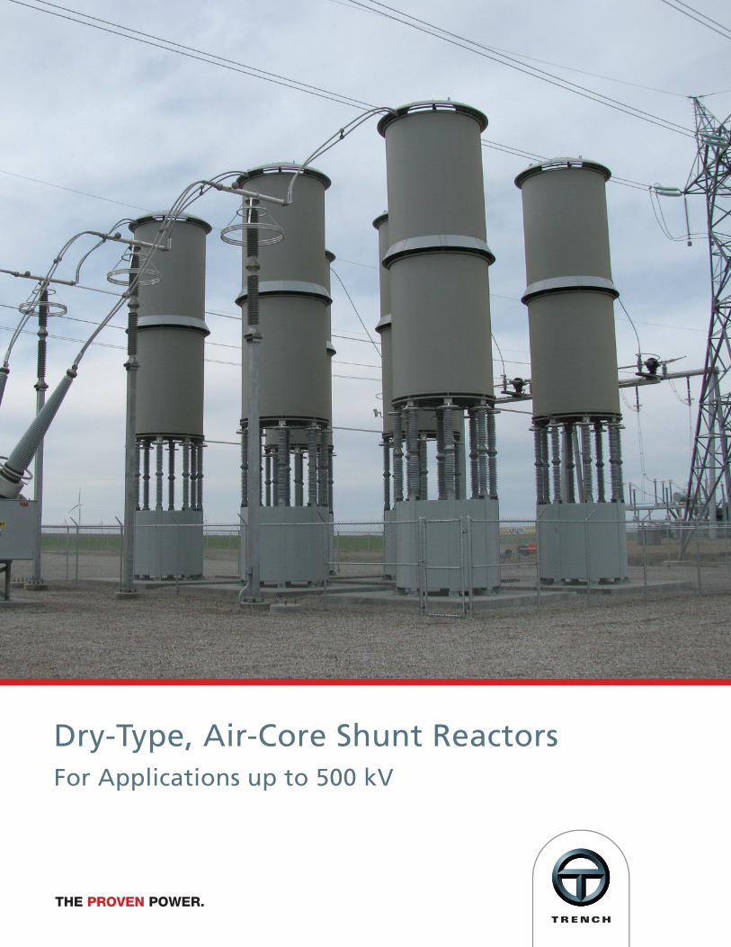
Dry-Type, Air-Core Shunt ReactorsFor Applications up to 500 kV
2THE PROVEN POWER.www.trench-group.com
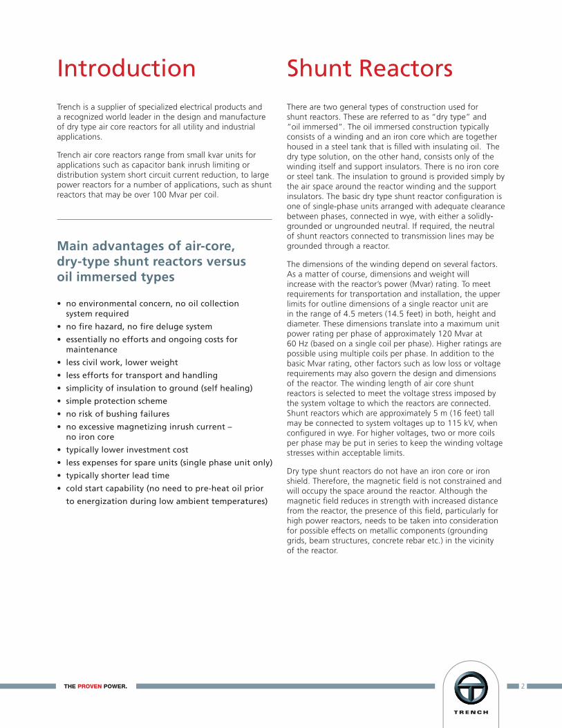
Trench is a supplier of specialized electrical products and a recognized world leader in the design and manufacture of dry type air core reactors for all utility and industrial applications.
Trench air core reactors range from small kvar units for applications such as capacitor bank inrush limiting or distribution system short circuit current reduction, to large power reactors for a number of applications, such as shunt reactors that may be over 100 Mvar per coil.
There are two general types of construction used for shunt reactors. These are referred to as “dry type” and “oil immersed”. The oil immersed construction typically consists of a winding and an iron core which are together housed in a steel tank that is filled with insulating oil. The dry type solution, on the other hand, consists only of the winding itself and support insulators. There is no iron core or steel tank. The insulation to ground is provided simply by the air space around the reactor winding and the support insulators. The basic dry type shunt reactor configuration is one of single-phase units arranged with adequate clearance between phases, connected in wye, with either a solidly-grounded or ungrounded neutral. If required, the neutral of shunt reactors connected to transmission lines may be grounded through a reactor.
The dimensions of the winding depend on several factors. As a matter of course, dimensions and weight will increase with the reactor’s power (Mvar) rating. To meet requirements for transportation and installation, the upper limits for outline dimensions of a single reactor unit are in the range of 4.5 meters (14.5 feet) in both, height and diameter. These dimensions translate into a maximum unit power rating per phase of approximately 120 Mvar at 60 Hz (based on a single coil per phase). Higher ratings are possible using multiple coils per phase. In addition to the basic Mvar rating, other factors such as low loss or voltage requirements may also govern the design and dimensions of the reactor. The winding length of air core shunt reactors is selected to meet the voltage stress imposed by the system voltage to which the reactors are connected. Shunt reactors which are approximately 5 m (16 feet) tall may be connected to system voltages up to 115 kV, when configured in wye. For higher voltages, two or more coils per phase may be put in series to keep the winding voltage stresses within acceptable limits.
Dry type shunt reactors do not have an iron core or iron shield. Therefore, the magnetic field is not constrained and will occupy the space around the reactor. Although the magnetic field reduces in strength with increased distance from the reactor, the presence of this field, particularly for high power reactors, needs to be taken into consideration for possible effects on metallic components (grounding grids, beam structures, concrete rebar etc.) in the vicinity of the reactor.
Introduction Shunt Reactors
Main advantages of air-core, dry-type shunt reactors versus oil immersed types
• no environmental concern, no oil collection system required
• no fire hazard, no fire deluge system
• essentially no efforts and ongoing costs for maintenance
• less civil work, lower weight
• less efforts for transport and handling
• simplicity of insulation to ground (self healing)
• simple protection scheme
• no risk of bushing failures
• no excessive magnetizing inrush current – no iron core
• typically lower investment cost
• less expenses for spare units (single phase unit only)
• typically shorter lead time
• cold start capability (no need to pre-heat oil prior
to energization during low ambient temperatures)

As the name implies, shunt reactors are connected in a parallel (shunt) configuration to the power system to compensate for the capacitive reactive power of transmission and distribution systems and thereby to keep the operating voltages within admissible levels.
Two main applications of shunt reactors can be identified: a) reactors that are required permanently in service for stability reasons (especially on long transmission lines), or b) that are needed for voltage control in a meshed system and are switched in only during light load conditions, when there is an excess of capacitive reactive power.
Depending on several factors shunt reactors may be connected (1) either to the tertiary winding of a power transformer, or (2) directly to the station busbar, or (3) to transmission line terminations (3), as shown in Fig. 1.
Tertiary connected shunt reactors
Depending on the customer’s requirements the reactive power rating of shunt reactors connected to the tertiary winding of a power transformer may vary from a few Mvar up to approximately 100 Mvar per phase. Because of their cost benefits, distribution class reactors in general and tertiary connected shunt reactors in particular, are usually of dry type design. Since the connection voltage at the tertiary is 34.5 kV or less, the voltage rating of the shunt reactor is usually not a controlling factor in the selection of the winding length. As a result the reactor may be designed with an optimum shape for minimum conductor length and thus for minimum cost. Such designs usually constitute the most cost effective solution for reactive power compensation. Fig. 2 shows a distribution class shunt reactor bank - 20 kV, 45 Mvar 3-phase, 50 Hz.
Application of Shunt Reactors
(1)
(3) (3)(2)
Fig. 1: Shunt reactor application in power systems
Fig. 2: 20 kV, 45 Mvar 3-phase tertiary shunt reactor
3THE PROVEN POWER.www.trench-group.com
4THE PROVEN POWER.www.trench-group.com
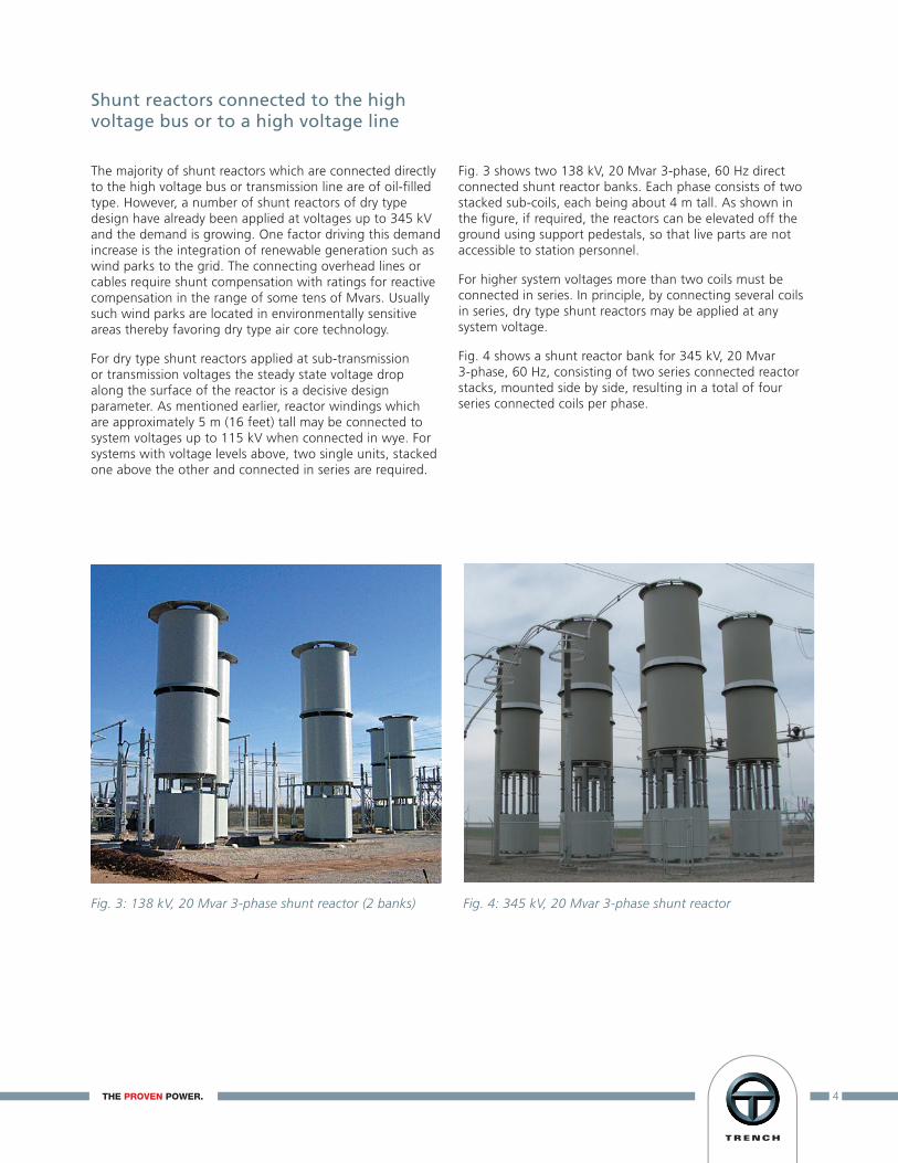
The majority of shunt reactors which are connected directly to the high voltage bus or transmission line are of oil-filled type. However, a number of shunt reactors of dry type design have already been applied at voltages up to 345 kV and the demand is growing. One factor driving this demand increase is the integration of renewable generation such as wind parks to the grid. The connecting overhead lines or cables require shunt compensation with ratings for reactive compensation in the range of some tens of Mvars. Usually such wind parks are located in environmentally sensitive areas thereby favoring dry type air core technology.
For dry type shunt reactors applied at sub-transmission or transmission voltages the steady state voltage drop along the surface of the reactor is a decisive design parameter. As mentioned earlier, reactor windings which are approximately 5 m (16 feet) tall may be connected to system voltages up to 115 kV when connected in wye. For systems with voltage levels above, two single units, stacked one above the other and connected in series are required.
Fig. 3 shows two 138 kV, 20 Mvar 3-phase, 60 Hz direct connected shunt reactor banks. Each phase consists of two stacked sub-coils, each being about 4 m tall. As shown in the figure, if required, the reactors can be elevated off the ground using support pedestals, so that live parts are not accessible to station personnel.
For higher system voltages more than two coils must be connected in series. In principle, by connecting several coils in series, dry type shunt reactors may be applied at any system voltage.
Fig. 4 shows a shunt reactor bank for 345 kV, 20 Mvar 3-phase, 60 Hz, consisting of two series connected reactor stacks, mounted side by side, resulting in a total of four series connected coils per phase.
Shunt reactors connected to the highvoltage bus or to a high voltage line
Fig. 3: 138 kV, 20 Mvar 3-phase shunt reactor (2 banks) Fig. 4: 345 kV, 20 Mvar 3-phase shunt reactor

5THE PROVEN POWER.www.trench-group.com
The majority of faults on transmission lines are single-phase-to-ground faults caused by flashovers of the air insulation. Clearing of such faults is achieved by making use of the dielectric recovery of the air. For this purpose the affected phase of the line is temporarily isolated by opening the circuit breaker at both line ends and reclosing the breakers after a certain dead time. This operation is termed single-phase auto-reclosing (SPAR).
Long EHV transmission lines are usually operated with shunt reactors permanently connected to the lines at their terminal stations, even when the lines are switched-off. Successful SPAR on such compensated lines is hampered by a phenomenon called secondary arcing. Instead of the extinction of the (primary) arc, the arc is further maintained due to capacitive and inductive coupling with the two healthy phases. A successful auto-reclosing is achieved only if this secondary arc extinguishes during the dead time when the breakers are open. For mitigation of secondary arcing it is a well proven practice to increase the zero sequence impedance of the shunt reactor by providing an additional single-phase reactor between the reactor’s neutral and ground.
During normal operation, the neutral reactor is practically unloaded. In case of a SPAR operation, for less than one or two seconds the reactor is loaded by typically 15 to 25 % of the system voltage, depending on the parameters of the line to which the shunt reactor is connected. The short-time power rating of the neutral reactor is only a few percent of the shunt reactor’s continuous power rating.
Due to the advantages of dry type over oil type reactors, practically all neutral reactors are dry type, for both oil immersed and dry type shunt reactors.
Switching of shunt reactors
Switching shunt reactors is one of the most severe duties for a circuit breaker. As a consequence, when applying shunt reactors, whether they be dry type or oil immersed, tertiary type or direct connected, it is extremely important to pay particular attention to the switching device which is selected and ensure it is capable of handling the task to which it is being applied. Guidance can be found in IEEE Std. C37.015-2009: IEEE Guide for the Application of Shunt Reactor Switching.
Fig. 5: Air core dry type neutral grounding reactor
X1: positive-sequence reactance of the shunt reactor
X0: zero-sequence reactance of the shunt reactor
(including the neutral reactor)
wye-connected shunt reactorwith directly grounded neutral
X0 / X
1 ≤ 1
wye-connected shunt reactorwith neutral grounded through a reactor
X0 / X
1 > 1
Wye connected shunt reactors with theneutral grounded through a neutral reactor
6THE PROVEN POWER.www.trench-group.com
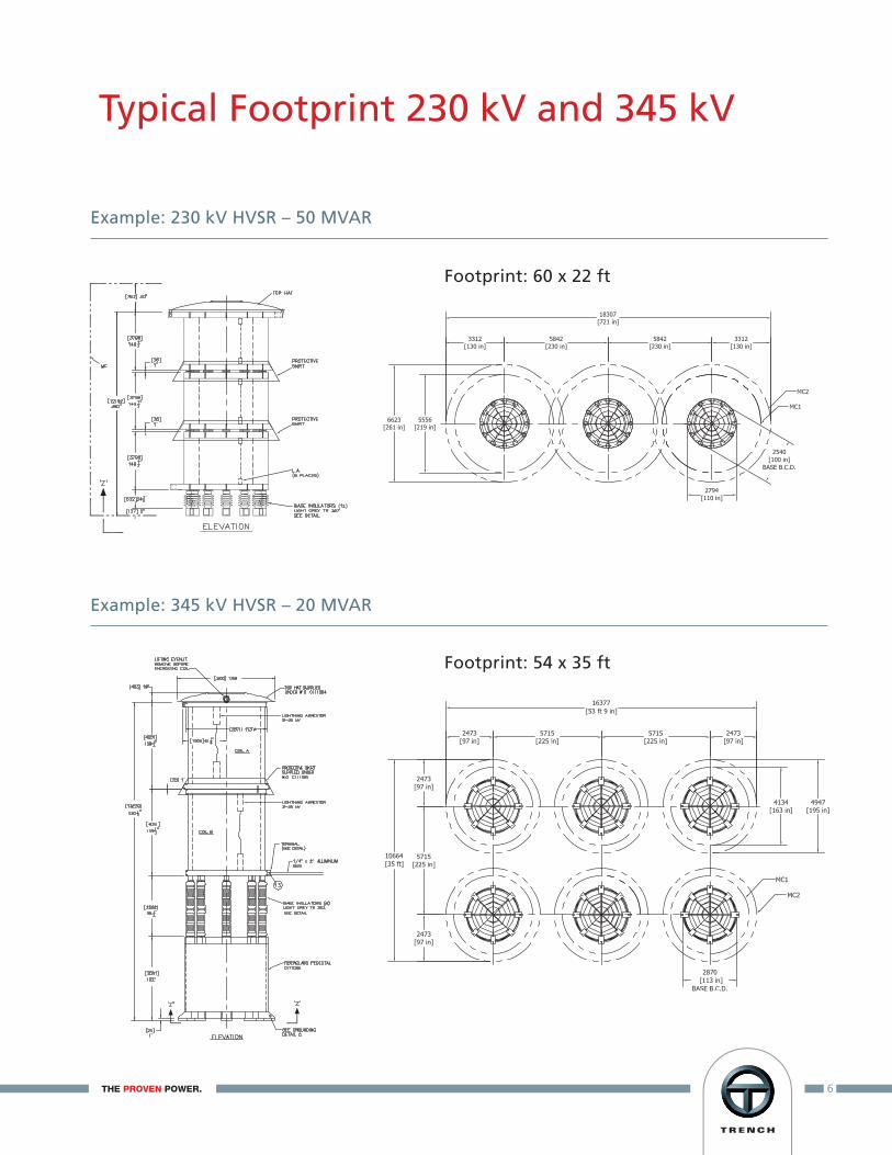
Typical Footprint 230 kV and 345 kV
Example: 230 kV HVSR – 50 MVAR
Example: 345 kV HVSR – 20 MVAR
Footprint: 60 x 22 ft
Footprint: 54 x 35 ft
7THE PROVEN POWER.www.trench-group.com
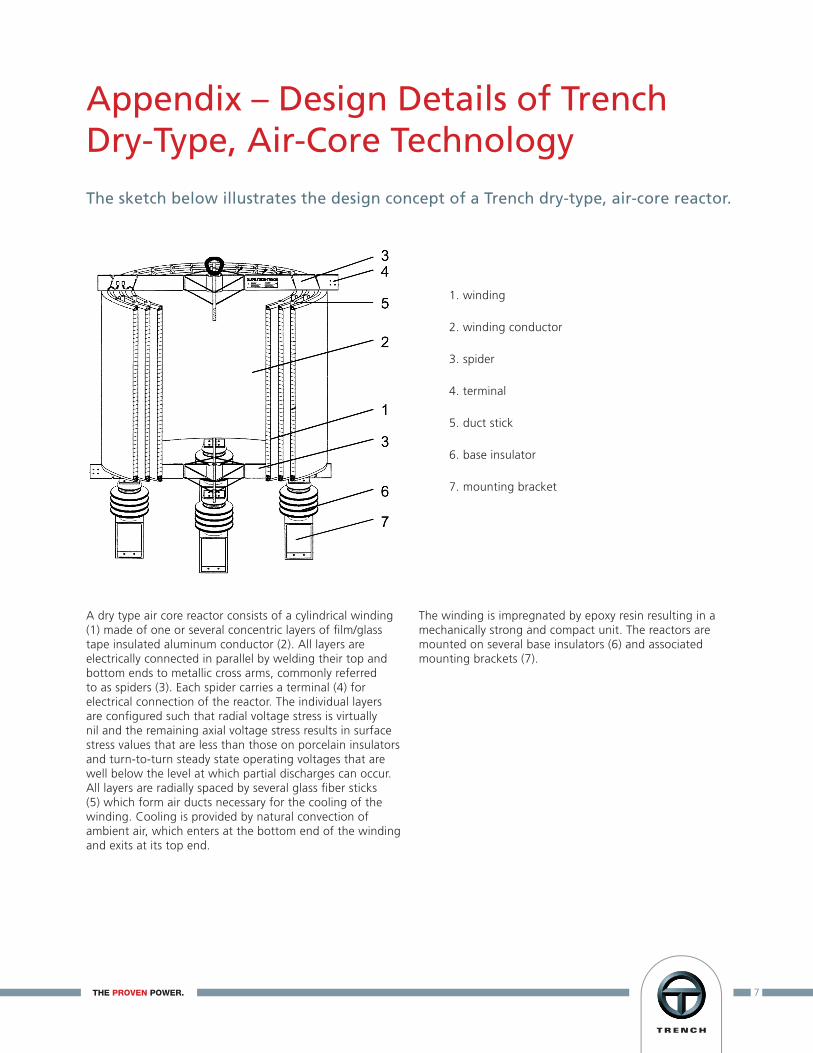
1. winding
2. winding conductor
3. spider
4. terminal
5. duct stick
6. base insulator
7. mounting bracket
A dry type air core reactor consists of a cylindrical winding (1) made of one or several concentric layers of film/glass tape insulated aluminum conductor (2). All layers are electrically connected in parallel by welding their top and bottom ends to metallic cross arms, commonly referred to as spiders (3). Each spider carries a terminal (4) for electrical connection of the reactor. The individual layers are configured such that radial voltage stress is virtually nil and the remaining axial voltage stress results in surface stress values that are less than those on porcelain insulators and turn-to-turn steady state operating voltages that are well below the level at which partial discharges can occur. All layers are radially spaced by several glass fiber sticks (5) which form air ducts necessary for the cooling of the winding. Cooling is provided by natural convection of ambient air, which enters at the bottom end of the winding and exits at its top end.
The winding is impregnated by epoxy resin resulting in a mechanically strong and compact unit. The reactors are mounted on several base insulators (6) and associated mounting brackets (7).
Appendix – Design Details of Trench Dry-Type, Air-Core Technology
The sketch below illustrates the design concept of a Trench dry-type, air-core reactor.
Trench Factories
The Trench Group is your partner of choice for electricalpower transmission and distribution solutions today andfor the development of your new technology solutionsof tomorrow.
Trench Austria GmbHPaschinger Strasse 49Postfach 13A-4060 Linz-LeondingAustriaPhone: +43-732-6793-0Fax: +43-732-671341
Trench Brasil (Siemens Ltda.)Avenida Eng. Joao F G Molina, 1745Jundiaí, Sao PauloCEP 13213-080BrazilPhone: +55-11-4585-2000Fax: + 55-11-4585-2042
Trench ChinaMWB (Shanghai) Co., Ltd.No. 3658, Jiancheng RoadMinhang, ShanghaiP. R. China200245Phone: +86-21-54720088Fax: +86-21-54723118
Trench France S.A.16, Rue du Général CassagnouB.P. 70 F-68 302St. Louis, CedexFrancePhone : +33-3-89-70-2323Fax : +33-3-89-67-2663
Trench Germany GmbHNürnberger Strasse 199D-96050 BambergGermanyPhone: +49-951-1803-0Fax: +49-951-1803-224
Trench High Voltage Products Ltd.,ShenyangNo. 2 Zhengliang Er. RoadJing Shen Xi San StreetDao Yi Economic Development ZoneShenyang 110136 P. R. ChinaPhone: +86-24-89722688Fax: +86-24-289737200
Trench Italia S.r.l.Strada Curagnata, 37IT-17014 BragnoCairo, Montenotte (SV)ItalyPhone; +39-019-5161-111Fax: +39-019-5161-401
Trench LimitedCoil Products Division71 Maybrook DriveScarborough, OntarioCanada M1V 4B6Phone: +1-416-298-8108Fax: +1-416-298-2209
Trench LimitedInstrument Transformer Division1865 Clements RoadPickering, OntarioCanada L1W 3R8Phone: +1-416-751-8570Fax: +1-416-751-6952
Trench LimitedPower Line Carrier Division330 Finchdene SquareScarborough, OntarioCanada M1X 1A5Phone: +1-416-847-5400Fax: +1-416-291-5581
THE PROVEN POWER.www.trench-group.com