Embed Size (px)
DESCRIPTION
Dry gas seal construction and operation for centrifugal compressor
Citation preview

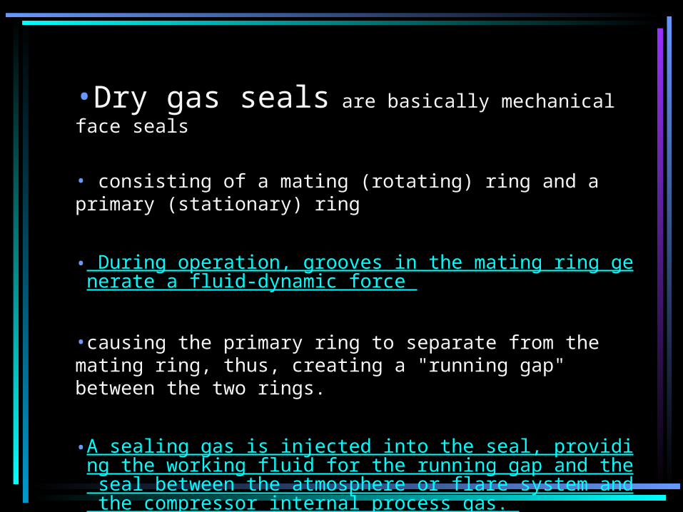
•Dry gas seals are basically mechanical face seals
• consisting of a mating (rotating) ring and a primary (stationary) ring
• During operation, grooves in the mating ring generate a fluid-dynamic force
•causing the primary ring to separate from the mating ring, thus, creating a "running gap" between the two rings.
•A sealing gas is injected into the seal, providing the working fluid for the running gap and the seal between the atmosphere or flare system and the compressor internal process gas.

Dry Gas Seal Arrangement

Typical Dry gas seal

Seal Face of Dry gas
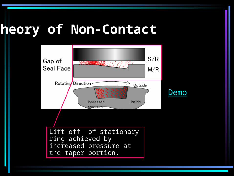
Theory of Non-ContactTheory of Non-Contact
Lift off of stationary ring achieved by increased pressure at the taper portion.
Demo

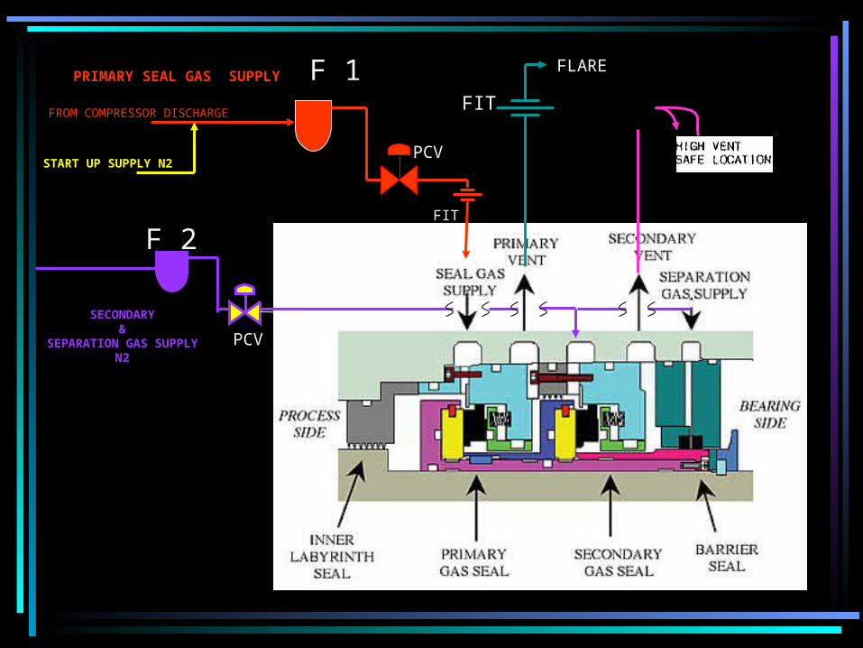
Dry Gas Seal Arrangement in K-2115/K-4115

Dry Gas Seal Arrangement in K-2115/K-4115
F 1
F 2
FIT
FLARE
SECONDARY&
SEPARATION GAS SUPPLYN2
PRIMARY SEAL GAS SUPPLY
FROM COMPRESSOR DISCHARGE
START UP SUPPLY N2PCV
PCV
FIT

Dry Gas Seal Supply Console - P&ID

Primary Seal Gas is, typically, Filtered gas from the compressor Primary Seal Gas is, typically, Filtered gas from the compressor discharge side, injected in to the Seal Chamber (the primary discharge side, injected in to the Seal Chamber (the primary inboard seal chamber)inboard seal chamber)
A major part of the this injected gas will flow back to the A major part of the this injected gas will flow back to the compressor through the inner labyrinth at the process gas side.compressor through the inner labyrinth at the process gas side.
This achieves the prevention of emissions from the compressor This achieves the prevention of emissions from the compressor to to the atmosphere.the atmosphere.
A small quantity of gas will pass thro the dynamically A small quantity of gas will pass thro the dynamically separated gap of seal faces to the intermediate chamber between separated gap of seal faces to the intermediate chamber between the inboard &outboard sealsthe inboard &outboard seals
Since this cavity is vented, the rate ( quantity per minute) of gas Since this cavity is vented, the rate ( quantity per minute) of gas flowing out is measured downstream.flowing out is measured downstream.
This is the indication of the leakage rate of the seal. This is the indication of the leakage rate of the seal.
A minimum rate of leakage will be always present. Increase in A minimum rate of leakage will be always present. Increase in the rate of leakage beyond design limits indicates reduced seal the rate of leakage beyond design limits indicates reduced seal performance/ Efficiencyperformance/ Efficiency
Understanding Seal Gas Supplies to Dry Gas SealUnderstanding Seal Gas Supplies to Dry Gas SealPrimary SealPrimary Seal

Understanding Seal Gas Supplies to Dry Gas SealUnderstanding Seal Gas Supplies to Dry Gas Seal
Secondary Seal is a backup seal which seals the leakageSecondary Seal is a backup seal which seals the leakage
from primary seal chamber from primary seal chamber
Nitrogen is injected in to this secondary Seal ChamberNitrogen is injected in to this secondary Seal Chamber
The Secondary Seal Functions as a safety seal to avoid emissions to The Secondary Seal Functions as a safety seal to avoid emissions to atmosphere in case of excessive leakage in the primary seal atmosphere in case of excessive leakage in the primary seal
Separation seal ( Barrier seal) Separation seal ( Barrier seal) This seal also works in conjunction with a separation labyrinth This seal also works in conjunction with a separation labyrinth situated situated between the bearing housings and Seal Chambersbetween the bearing housings and Seal Chambers
The separation gas is also Nitrogen, injected in to the separation The separation gas is also Nitrogen, injected in to the separation labyrinthlabyrinth
The main purpose of Separation gas supply is to prevent the oil in The main purpose of Separation gas supply is to prevent the oil in the the bearing side from entering the seal Chamber. bearing side from entering the seal Chamber.
Presence oil in the seal chamber will cause Presence oil in the seal chamber will cause
damage to the Dry gas seal componentsdamage to the Dry gas seal components
Secondary Seal Secondary Seal ( Containment seal )( Containment seal )

Operational Guide Lines –Dry Gas Operational Guide Lines –Dry Gas SealsSeals
Seal Gas Supply QualitySeal Gas Supply QualityThe Quality of Gas fed to the seals must be clean and Dry- The Quality of Gas fed to the seals must be clean and Dry- Coalescing Filters to filter 2 microns shall be used in the Coalescing Filters to filter 2 microns shall be used in the Dry gas Supply Console. Pressure Drop across the Filters shall be Dry gas Supply Console. Pressure Drop across the Filters shall be monitored and filters must be renewed to achieve good seal performancemonitored and filters must be renewed to achieve good seal performance
Seal Gas Supply flowSeal Gas Supply flowThe seal gas supply flow must be sufficient enough to ensure that the seal isThe seal gas supply flow must be sufficient enough to ensure that the seal isSupplied with sufficient filtered gas during operation with excess gas going back Supplied with sufficient filtered gas during operation with excess gas going back in to the Compressor casing. This is will provide an ideal sealing environment in to the Compressor casing. This is will provide an ideal sealing environment to maintain the optimum seal performanceto maintain the optimum seal performance
Seal Gas Leakage TrendsSeal Gas Leakage TrendsSeal performance is monitored through leakage trends. Seal performance is monitored through leakage trends. Occasional SpikesOccasional SpikesIn the leakage due process parameter variations, shaft In the leakage due process parameter variations, shaft movement, speed changes are movement, speed changes are no cause for alarmno cause for alarm. But . But persistent trend of higher leakage may give a forewarning of seal persistent trend of higher leakage may give a forewarning of seal problems problems
11

Operational Guide Lines –Dry Gas SealsOperational Guide Lines –Dry Gas Seals 22
Reverse Rotation Reverse Rotation Reverse Rotation should be avoided as it will damage the Reverse Rotation should be avoided as it will damage the delicate parts of a Dry Gas Sealdelicate parts of a Dry Gas Seal
Reverse Pressure Reverse Pressure
Reverse pressure under static condition will result in an increase in static leakage. Reverse pressure under static condition will result in an increase in static leakage.
Under Dynamic condition, reverse pressure can result major damageUnder Dynamic condition, reverse pressure can result major damage
to the Dry Gas Seal System components.to the Dry Gas Seal System components.
Slow RollSlow Roll
In Turbine Driven compressors Slow roll below 1000 rpm be avoided. In Turbine Driven compressors Slow roll below 1000 rpm be avoided.
The separation of seal faces will not be achieved under such condition. The separation of seal faces will not be achieved under such condition.
Seal faces will be running with contact which will damage Seal faces will be running with contact which will damage
the geometry of the grooves in the seal facethe geometry of the grooves in the seal face