Embed Size (px)
Citation preview

1SLVUBB8B–January 2018–Revised April 2019Submit Documentation Feedback
Copyright © 2018–2019, Texas Instruments Incorporated
DRV8343H-Q1EVM and DRV8343S-Q1EVM User's Guide
User's GuideSLVUBB8B–January 2018–Revised April 2019
DRV8343H-Q1EVM and DRV8343S-Q1EVM User's Guide
This document is provided with the DRV8343H-Q1EVM and DRV8343S-Q1EVM customer evaluationmodules (EVMs) as a supplement to the DRV8343-Q1 Automotive 5.5 to 60-V Three-Phase Smart GateDriver With Three Integrated Current-Shunt Amplifiers data sheet. The scope of this document is toprovide the user with a guide to evaluate the DRV8343x-Q1EVM. This document details the hardwareimplementation of the EVM and how to use the DRV8343x-Q1EVM with the provided software.
Contents1 Overview ...................................................................................................................... 22 Hardware and Software Overview......................................................................................... 3
2.1 Hardware Overview................................................................................................. 32.2 Hardware Setup..................................................................................................... 72.3 Software and Tools Overview ..................................................................................... 8
List of Figures
1 DRV8343x-Q1EVM Top View.............................................................................................. 22 Board Overview .............................................................................................................. 33 Connections Overview ..................................................................................................... 44 DRV8343H-Q1EVM ......................................................................................................... 55 DRV8343x-Q1EVM BLDC Configuration ................................................................................. 66 DRV8343x-Q1 Hardware Setup ........................................................................................... 77 CCS v6 or Above Required ................................................................................................ 88 DRV8343-Q1 Firmware Installer Executable File ....................................................................... 89 Language Selection ......................................................................................................... 910 Setup Home Screen ........................................................................................................ 911 DRV8343-Q1 Software License Agreement ............................................................................ 1012 Setup Destination Folder .................................................................................................. 1113 Select DRV8343-Q1 Setup Components ............................................................................... 1114 Warning Message to Close CCS......................................................................................... 1215 Setup Ready to Install ..................................................................................................... 1216 Installing Firmware ......................................................................................................... 1317 Firmware Setup Complete ................................................................................................ 1318 Open CCS Application..................................................................................................... 1419 Workspace Selection ...................................................................................................... 1420 Importing CSS Project ..................................................................................................... 1521 Select DR8343_EVM_BLDC_FW_1.0.0 Folder........................................................................ 1522 Select Projects to Import ................................................................................................. 1623 Project Explorer ............................................................................................................ 1724 Build and Debug............................................................................................................ 1725 Run and Pause Debug Session.......................................................................................... 1726 GUI Executable............................................................................................................. 1827 Setup GUI Home Screen.................................................................................................. 1828 License Agreement ........................................................................................................ 19

Interface Connection
MSP430 PowerStage
To Motor
To Power Supply
Micro-USB
Reverse BatteryProtection
Overview www.ti.com
2 SLVUBB8B–January 2018–Revised April 2019Submit Documentation Feedback
Copyright © 2018–2019, Texas Instruments Incorporated
DRV8343H-Q1EVM and DRV8343S-Q1EVM User's Guide
29 Installation Directory ....................................................................................................... 1930 Ready to Install ............................................................................................................. 2031 Installing the GUI ........................................................................................................... 2032 GUI Setup Complete....................................................................................................... 2133 FTDI Driver Installation .................................................................................................... 21
List of Tables
1 IDRIVE, MODE, and VDS Input Control Settings ....................................................................... 52 GAIN Input Control Settings................................................................................................ 53 Hall Sensor Signal Connections to the DRV8343x-Q1EVM ........................................................... 7
TrademarksMSP430, Code Composer Studio are trademarks of Texas Instruments.All other trademarks are the property of their respective owners.
1 OverviewThe DRV8343x-Q1EVM is a fully functional, highly configurable three-phase brushless DC (BLDC) motordriver evaluation platform designed for 12-V to 24-V systems and up to 20-A maximum load. The EVM isdesigned to highlight the DRV8343x-Q1, a three-phase BLDC motor gate driver for automotiveapplications. The DRV8343x-Q1EVM can also be used to evaluate the DRV8340x-Q1, which features thesame gate drive performance, but does not include the three current sense amplifiers. The DRV8343x-Q1EVM is also designed to be configured in different independent mode settings to drive unidirectionalmotors, solenoids, or both.
The DRV8343-Q1 device is used in motor control applications that require a high degree of integratedprotection, diagnosis, and monitoring. Both SPI (DRV8343S) and hardware (DRV8343H) interface variantsprovide detailed fault reporting and flexible parameter settings such as current control options for slew-ratecontrol of the gate drivers and various protection features. Figure 1 shows the top 3D view of theDRV8343x-Q1EVM highlighting the key components of the board.
Figure 1. DRV8343x-Q1EVM Top View

MSP430F5529 LM2936QDT
CSD18543Q3A DRV8343x-Q1 6x CSD88584Q5DC
www.ti.com Hardware and Software Overview
3SLVUBB8B–January 2018–Revised April 2019Submit Documentation Feedback
Copyright © 2018–2019, Texas Instruments Incorporated
DRV8343H-Q1EVM and DRV8343S-Q1EVM User's Guide
2 Hardware and Software Overview
2.1 Hardware Overview
2.1.1 FeaturesThe following lists the DRV8343x-Q1EVM key features:• Operating supply range from 6 V to 48 V• Six CSD18540Q5B N-channel NexFETs driven by the gate driver• Protected phase voltages provided to header pins through a voltage divider• Connector available for Hall sensor inputs connected to the MSP430™ MCU.• Includes sample code for sensored and sensoreless BLDC implementation• Includes sample code for independent mode to drive BDC motors and solenoids configurations
2.1.2 DRV8343x-Q1EVM OverviewFigure 2 shows the major blocks of the hardware on the DRV8343x-Q1EVM.
Figure 2. Board Overview
Spy-Bi-WireConnection
Micro-USB
Test Points
3.3 V
VM
Power
High-sideSource
Headers
Gate HeadersHalls Voltage
SelectionHalls SensoConnection
To Motor
5V
Hardware and Software Overview www.ti.com
4 SLVUBB8B–January 2018–Revised April 2019Submit Documentation Feedback
Copyright © 2018–2019, Texas Instruments Incorporated
DRV8343H-Q1EVM and DRV8343S-Q1EVM User's Guide
• DRV8343-Q1 (U4): automotive 5.5 to 60-V three-phase Smart Gate Driver with three integratedcurrent-shunt amplifiers
• MSP430F5529 (U1): 25-MHz mixed signal microcontroller with 128 KB Flash, 8192 B SRAM, and 63GPIOs
• LM2936Q-Q1 (U3): ultralow quiescent current LDO voltage regulator• CSD18543Q3A (Q1): MOSFET, N-CH, 60 V, 35 A• CSD18540Q5B (Q3,Q4,Q5,Q6,Q7,Q8): MOSFET, N-CH, 60 V, 100 A
CAUTION
HOT SURFACE: Contact may cause burns. Do not touch.
2.1.3 Pinout, Connectors, and Jumpers OverviewFigure 3 shows the board connectors and various test points on the DRV8343x-Q1EVM.
Figure 3. Connections Overview

Gain VDS Mode IDRIVE
www.ti.com Hardware and Software Overview
5SLVUBB8B–January 2018–Revised April 2019Submit Documentation Feedback
Copyright © 2018–2019, Texas Instruments Incorporated
DRV8343H-Q1EVM and DRV8343S-Q1EVM User's Guide
Figure 4 shows the various header connections available on the DRV8343H-Q1EVM that are used toconfigure the control inputs to the DRV8343H-Q1 device.
Figure 4. DRV8343H-Q1EVM
Table 1 and Table 2 list each of these jumper locations, starting from the right side of each jumper header.
Table 1. IDRIVE, MODE, and VDS Input Control Settings
JUMPERLOCATION CONNECTION IDRIVE
(SINK/SOURCE) MODE VDS
First Tied to DVDD 1 A / 2 A Independent FET mode Disabled
Second 18-kΩ resistor to DVDD 260 mA / 520 mA
Phase A in independent half-bridgemodePhase B and phase C in independentFET mode
1.88 V
Third 75-kΩ resistor to DVDD 200 mA / 400 mAPhase B and phase C in independenthalf-bridge modePhase A in independent FET mode
1.13 V
Forth 75-kΩ resistor to Ground 60 mA / 120 mA 1 x PWM 0.26 VFifth 18-kΩ resistor to Ground 10 mA / 20 mA 3 x PWM 0.13 VSixth Tied to Ground 5 mA / 10 mA 6 x PWM 0.06 VNo jumperconnector Hi-Z mode 1.5 mA / 3 mA Independent half-bridge mode 0.6 V
Table 2. GAIN Input Control Settings
JUMPER LOCATION CONNECTION GAINFirst Tied to DVDD 40 V/VSecond 47-kΩ resistor to DVDD 10 V/VThird Tied to Ground 5 V/VNo jumper connection Hi-Z mode 20 V/V

SHx ± DLx JumperConnector for
BLDC Operation
2-pinPhase C
2-pinPhase B
2-pinPhase A
Hardware and Software Overview www.ti.com
6 SLVUBB8B–January 2018–Revised April 2019Submit Documentation Feedback
Copyright © 2018–2019, Texas Instruments Incorporated
DRV8343H-Q1EVM and DRV8343S-Q1EVM User's Guide
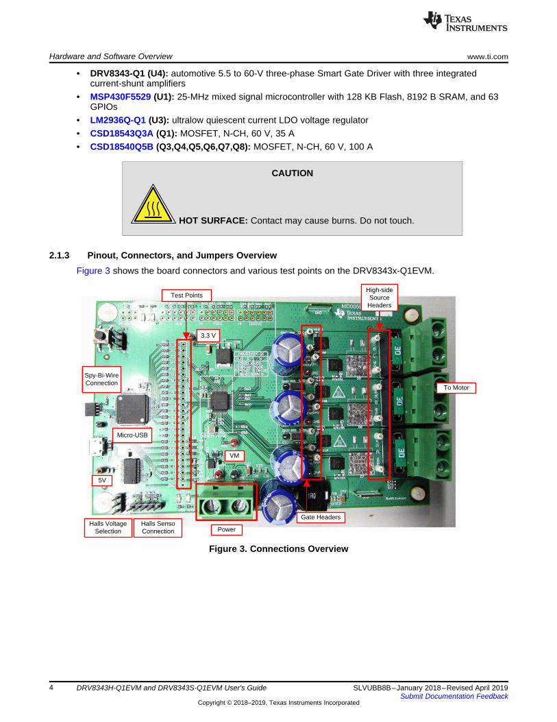
Both the DRV8343S-Q1EVM and DRV8343H-Q1EVM are configured as a BLDC driver board. The F2, F3,and F4 jumper connectors come preinstalled with the SHx pin connected to the DLx output of theDRV8343-Q1 device. The three-phase motor leads can then be connected to any of the 2-pin terminalconnectors for the A, B, and C phase headers (H5, H6, and H7 respectively) as shown in Figure 5.
Figure 5. DRV8343x-Q1EVM BLDC Configuration
To configure the EVM board in an independent mode configuration, refer to the DRV8343x-Q1EVMIndependent Mode User's Guide.
2.1.4 Hardware, Software, and Tools Required for EvaluationThe software, hardware, and tools required to optimally evaluate the reference software code with theDRV8343x-Q1EVM are listed as follows:• DRV8343x-Q1EVM• Voltage supply from 6 V to 48 V• Code Composer Studio™ software V.6.1 and above• DRV8343x-Q1EVM GUI software• DRV8343x-Q1EVM reference software development package (if different sensored firmware or
independent mode is required)• Spy-Bi-Wire programmer such as the MSP430G2553 LaunchPad™ development kit (If different
sensored firmware or independent mode is required)
2.1.5 Hardware Connections for Hall Sensor OperationTable 3 lists the signal connections from the Hall sensor of the motor connected to jumper J6 on theDRV8343x-Q1EVM.
Additionally, the voltage supply for the Hall sensors can be adjusted from 3.3 V to 5 V for Hall sensorsrequiring 5-V power operation. The Hall power is configured by default for a 3.3-V supply. For a 5-Vsupply, the jumper should be place close to the J5 designator.

To Motor
Micro-USB
Power
www.ti.com Hardware and Software Overview
7SLVUBB8B–January 2018–Revised April 2019Submit Documentation Feedback
Copyright © 2018–2019, Texas Instruments Incorporated
DRV8343H-Q1EVM and DRV8343S-Q1EVM User's Guide
NOTE: The 5-V supply is routed through the J2 connection and provided by the micro-USB port.The GUI is assumed to be used for Hall sensored operation, and therefore the 5-V supplyshould be provided this way.
Table 3. Hall Sensor Signal Connections to theDRV8343x-Q1EVM
SIGNAL DESCRIPTION EQUIVALENT ON DRV8343x-Q1EVMGND J6–1(-)Hall C J6–2(C)Hall B J6–3(B)Hall A J6–4(A)
Hall Power J6–5(+)
2.2 Hardware SetupUse the following steps to set up the DRV8343x-Q1EVM for evaluation:
Step 1. Confirm that the jumpers are configured correctly. For more information, see Section 2.1.3.Step 2. Connect the motor phase wires to the terminal block headers, H5, H6, and H7. The order of
the motor leads does not matter. The motor direction can be changed using the GUI or byreversing the direction of two of the motor phases.
Step 3. Connect the power supply to the terminal block header, H4. Make sure the polarity is correct:positive to VBAT, negative to GND. Do not enable the power supply at this time.
Step 4. Connect the micro-USB cable to the USB connector, J2. A cable is suppled with theDRV8343x-Q1EVM but any standard micro-USB cable should also work. Do not connect theEVM to the computer at this time.
Step 5. Enable the power supply. The VM power supply LED, D5, and the 3.3-V power supply LED,D3, should light up.
Step 6. Connect the micro-USB cable to the computer to run the GUI and interface with theDRV8343x-Q1EVM.
Figure 6. DRV8343x-Q1 Hardware Setup

Hardware and Software Overview www.ti.com
8 SLVUBB8B–January 2018–Revised April 2019Submit Documentation Feedback
Copyright © 2018–2019, Texas Instruments Incorporated
DRV8343H-Q1EVM and DRV8343S-Q1EVM User's Guide
2.3 Software and Tools OverviewThe DRV8343x-Q1EVM comes with the trapezoidal sensoreless algorithm firmware preloaded onto theMSP430F5529 microcontroller. The DRV8343x-Q1EVM SDK package also includes firmware for Hallsensored evaluation and independent mode configuration. The following section describes the steps toinstall and configure the additional firmware available in the SDK package.
2.3.1 Installing CCS for Optional Software EvaluationCode Composer Studio (CCS) version 6.1.0 or above is required to evaluate the for DRV8343-Q1Xreference codes. Install an authorized version from www.ti.com/tool/ccstudio.
NOTE: A myTI login account is required to download CCS as well as the SDK package.
Figure 7. CCS v6 or Above Required
2.3.2 Installing DRV8343-Q1 Reference Software Development PackageThe DRV8343-Q1 reference software contains the files required to program DRV8343-Q1 devices alongwith the MSP430F5529 using CCS v6.0.1. or above. All of these files are included in the installationpackage. To download this package, go to respective the EVMs tool page on TI.com (DRV8343H-Q1EVMor DRV8343S-Q1EVM).
Install the reference software development package using these steps:Step 1. Double click the executable file (.exe) for the DRV8343-Q1 reference software installer (see
Figure 8).
Figure 8. DRV8343-Q1 Firmware Installer Executable File
Step 2. Follow the prompts to select another language from the default of English (see Figure 9).

www.ti.com Hardware and Software Overview
9SLVUBB8B–January 2018–Revised April 2019Submit Documentation Feedback
Copyright © 2018–2019, Texas Instruments Incorporated
DRV8343H-Q1EVM and DRV8343S-Q1EVM User's Guide
Figure 9. Language Selection
Step 3. Click the Next button on the DRV8343-Q1 installer welcome screen (see Figure 10).
Figure 10. Setup Home Screen
Step 4. Read though and accept the license agreement to proceed with the installation (seeFigure 11).

Hardware and Software Overview www.ti.com
10 SLVUBB8B–January 2018–Revised April 2019Submit Documentation Feedback
Copyright © 2018–2019, Texas Instruments Incorporated
DRV8343H-Q1EVM and DRV8343S-Q1EVM User's Guide
Figure 11. DRV8343-Q1 Software License Agreement

www.ti.com Hardware and Software Overview
11SLVUBB8B–January 2018–Revised April 2019Submit Documentation Feedback
Copyright © 2018–2019, Texas Instruments Incorporated
DRV8343H-Q1EVM and DRV8343S-Q1EVM User's Guide
Step 5. Choose the destination location for the example CCS projects and the documentation (seeFigure 12). This destination can be set to any location in the PC.
Figure 12. Setup Destination Folder
Step 6. Select each DRV83x component to install (see Figure 13).
Figure 13. Select DRV8343-Q1 Setup Components

Hardware and Software Overview www.ti.com
12 SLVUBB8B–January 2018–Revised April 2019Submit Documentation Feedback
Copyright © 2018–2019, Texas Instruments Incorporated
DRV8343H-Q1EVM and DRV8343S-Q1EVM User's Guide
Step 7. Ensure all running instances of CCS are closed (see Figure 14).
Figure 14. Warning Message to Close CCS
Step 8. Continue with the installation process.
Figure 15. Setup Ready to Install
Step 9. Click the Next button to install after reviewing the settings.

www.ti.com Hardware and Software Overview
13SLVUBB8B–January 2018–Revised April 2019Submit Documentation Feedback
Copyright © 2018–2019, Texas Instruments Incorporated
DRV8343H-Q1EVM and DRV8343S-Q1EVM User's Guide
Figure 16. Installing Firmware
Step 10. Click the Finish button when the files are successfully installed in the destination folder (seeFigure 17).
Figure 17. Firmware Setup Complete

Hardware and Software Overview www.ti.com
14 SLVUBB8B–January 2018–Revised April 2019Submit Documentation Feedback
Copyright © 2018–2019, Texas Instruments Incorporated
DRV8343H-Q1EVM and DRV8343S-Q1EVM User's Guide
2.3.3 Creating or Importing a DRV8343-Q1 Project Into CCSWhen the CCS software is started, the user must first select a workspace. A workspace is the structure inwhich projects are kept. Multiple projects can be saved in one workspace. After importing an existingproject, the user can explore the features of CCS to become familiar with the IDE. Follow these steps toimport the provided project:
Step 1. Double click the CCS icon to open the application. A CCS icon is placed on the desktop afterinstallation.
Figure 18. Open CCS Application
Step 2. Select the location and name of the workspace. The location and naming convention can bechanged. (see Figure 19).
Step 3. Click the OK button to accept.
Figure 19. Workspace Selection
After selecting the workspace, the CCS software opens displaying a welcome menu.

www.ti.com Hardware and Software Overview
15SLVUBB8B–January 2018–Revised April 2019Submit Documentation Feedback
Copyright © 2018–2019, Texas Instruments Incorporated
DRV8343H-Q1EVM and DRV8343S-Q1EVM User's Guide
Step 4. Import a project either from the welcome menu by selecting Import Project or go to theProject menu and select Import Existing CCS Eclipse Project (see Figure 20).
Figure 20. Importing CSS Project
Step 5. In the new window that appears showing the import options, click the Browse... button andfind the provided projects through the folder browser. These projects are located in the SDKinstallation directory. The default location of the root folder is under C:\ti (see Figure 22).When selected, the provided project appears under Discovered Projects.
Figure 21. Select DR8343_EVM_BLDC_FW_1.0.0 Folder
Step 6. Make sure the correct box is checked and then click the Finish button (see Figure 22).

Hardware and Software Overview www.ti.com
16 SLVUBB8B–January 2018–Revised April 2019Submit Documentation Feedback
Copyright © 2018–2019, Texas Instruments Incorporated
DRV8343H-Q1EVM and DRV8343S-Q1EVM User's Guide
Figure 22. Select Projects to Import

www.ti.com Hardware and Software Overview
17SLVUBB8B–January 2018–Revised April 2019Submit Documentation Feedback
Copyright © 2018–2019, Texas Instruments Incorporated
DRV8343H-Q1EVM and DRV8343S-Q1EVM User's Guide
When the projects are imported to the workspace, the project should appear in the Project Explorerwindow as shown in Figure 23.
Figure 23. Project Explorer
Step 7. Explore the project files, build the project to create an image to be downloaded on theMSP430F5529 hardware, and download the project from here. Make sure the MSP430F5529is connected to the PC through USB interface before downloading the code.
Figure 24. Build and Debug
Step 8. When the CCS software is connected to the device, run the program from CCS to executethe program in hardware by clicking the green play button (see Figure 25). Click the red stopbutton (see Figure 25) to disconnect from the device debugger.
Figure 25. Run and Pause Debug Session

Hardware and Software Overview www.ti.com
18 SLVUBB8B–January 2018–Revised April 2019Submit Documentation Feedback
Copyright © 2018–2019, Texas Instruments Incorporated
DRV8343H-Q1EVM and DRV8343S-Q1EVM User's Guide
2.3.4 GUI Application
2.3.4.1 InstallationFollow these steps to install the GUI application:
Step 1. Download and run the Setup_DRV8343-xQ1-1.0.0_EVM_GUI.exe installer file to install theGUI application.
Figure 26. GUI Executable
Step 2. Click the Next button on the welcome screen of the DRV8343-Q1 installer (see Figure 27).
Figure 27. Setup GUI Home Screen
Step 3. Read though and accept the license agreement to proceed with the installation (seeFigure 28).

www.ti.com Hardware and Software Overview
19SLVUBB8B–January 2018–Revised April 2019Submit Documentation Feedback
Copyright © 2018–2019, Texas Instruments Incorporated
DRV8343H-Q1EVM and DRV8343S-Q1EVM User's Guide
Figure 28. License Agreement
Step 4. Review the new Setup window which lists the installation directory where the GUI files will beinstalled (see Figure 29). Click the Next button to proceed.
Figure 29. Installation Directory
Step 5. Click the Next button when the setup is complete and GUI installation is ready to start (see

Hardware and Software Overview www.ti.com
20 SLVUBB8B–January 2018–Revised April 2019Submit Documentation Feedback
Copyright © 2018–2019, Texas Instruments Incorporated
DRV8343H-Q1EVM and DRV8343S-Q1EVM User's Guide
Figure 30).
Figure 30. Ready to Install
Step 6. Click the Yes button in the new window to create a shortcut on the desktop if desired.The GUI then starts the installation (see Figure 31).
Figure 31. Installing the GUI

www.ti.com Hardware and Software Overview
21SLVUBB8B–January 2018–Revised April 2019Submit Documentation Feedback
Copyright © 2018–2019, Texas Instruments Incorporated
DRV8343H-Q1EVM and DRV8343S-Q1EVM User's Guide
Step 7. Click the Finish button when the files are successfully installed in the destination folder (seeFigure 32).
Figure 32. GUI Setup Complete
Step 8. The GUI uses an FTDI to enable USB communication. If the FTDI driver is not alreadyinstalled download the latest VCP window driver executable from the FTDI website(http://www.ftdichip.com/Drivers/VCP.htm)
Figure 33. FTDI Driver Installation

Revision History www.ti.com
22 SLVUBB8B–January 2018–Revised April 2019Submit Documentation Feedback
Copyright © 2018–2019, Texas Instruments Incorporated
Revision History
Revision HistoryNOTE: Page numbers for previous revisions may differ from page numbers in the current version.
Changes from A Revision (April 2018) to B Revision .................................................................................................... Page
• Added DRV8343x-Q1EVM can also be used to evaluate the DRV8340x-Q1 statement........................................ 2
Revision History
Changes from Original (January 2018) to A Revision .................................................................................................... Page
• Changed the maximum supply voltage from 60 V to 48 V in the Features and Hardware, Software, and Tools Required forEvaluation sections ....................................................................................................................... 3

IMPORTANT NOTICE AND DISCLAIMER
TI PROVIDES TECHNICAL AND RELIABILITY DATA (INCLUDING DATASHEETS), DESIGN RESOURCES (INCLUDING REFERENCEDESIGNS), APPLICATION OR OTHER DESIGN ADVICE, WEB TOOLS, SAFETY INFORMATION, AND OTHER RESOURCES “AS IS”AND WITH ALL FAULTS, AND DISCLAIMS ALL WARRANTIES, EXPRESS AND IMPLIED, INCLUDING WITHOUT LIMITATION ANYIMPLIED WARRANTIES OF MERCHANTABILITY, FITNESS FOR A PARTICULAR PURPOSE OR NON-INFRINGEMENT OF THIRDPARTY INTELLECTUAL PROPERTY RIGHTS.These resources are intended for skilled developers designing with TI products. You are solely responsible for (1) selecting the appropriateTI products for your application, (2) designing, validating and testing your application, and (3) ensuring your application meets applicablestandards, and any other safety, security, or other requirements. These resources are subject to change without notice. TI grants youpermission to use these resources only for development of an application that uses the TI products described in the resource. Otherreproduction and display of these resources is prohibited. No license is granted to any other TI intellectual property right or to any thirdparty intellectual property right. TI disclaims responsibility for, and you will fully indemnify TI and its representatives against, any claims,damages, costs, losses, and liabilities arising out of your use of these resources.TI’s products are provided subject to TI’s Terms of Sale (www.ti.com/legal/termsofsale.html) or other applicable terms available either onti.com or provided in conjunction with such TI products. TI’s provision of these resources does not expand or otherwise alter TI’s applicablewarranties or warranty disclaimers for TI products.
Mailing Address: Texas Instruments, Post Office Box 655303, Dallas, Texas 75265Copyright © 2019, Texas Instruments Incorporated