Embed Size (px)
Citation preview

DRONE-BASED 4G COMMUNICATION SYSTEM FOR
STRATEGIC AND PUBLIC PROTECTION AND
DISASTER RELIEF VOICE AND VIDEO
APPLICATIONS
A THESIS
Submitted by
SANJAY KUMAR HAOJAM
in partial fulfillment of the requirements
for the award of the degree of
MASTER OF TECHNOLOGY
DEPARTMENT OF ELECTRICAL ENGINEERING
INDIAN INSTITUTE OF TECHNOLOGY MADRAS
CHENNAI-600036
09 JUN 2020

§c Copyright Sanjay Kumar Haojam, June 2020
All rights reserved.

THESIS CERTIFICATE
This is to certify that the thesis titled “DRONE-BASED 4G COMMUNICATION
SYSTEM FOR STRATEGIC AND PUBLIC PROTECTION AND DISASTER
RELIEF VOICE AND VIDEO APPLICATIONS” submitted by SANJAY KUMAR
HAOJAM to the Indian Institute of Technology, Madras for the award of the degree of
Master of Technology, is a bona fide record of research work carried out by him under my
supervision. The contents of this thesis, in full or in parts, have not been submitted to any
other Institute or University for the award of any degree or diploma.
Dr. R. David Koilpillai
Project Guide
Professor
Department of Electrical Engineering
Indian Institute of Technology Madras
Chennai – 600 036
Place: Chennai
Date: 09 Jun 2020


i
ACKNOWLEDGEMENTS
I would like to take this opportunity to express my gratitude to our Research Guide,
Prof R. David Koilpillai for his constant and continued support and motivation all through
the project. His encouragement and guidance helped me put the subject in a presentable
shape. I have learnt a lot from him, be it academic knowledge or professionalism. He
provided me with the utmost environment and opportunities for my learning and growth and
helped me to be an able student.
I also thank Dr Devendra Jalihal, Professor, Dept of Electrical Engineering, IIT
Madras for his valuable advice for the betterment of the project. He helped me to understand
the concepts of different types of antenna system and setup a working prototype of the 4G
communication system and carry out its testing.
I would also like to express my sincere gratitude and acknowledgements to Smt
Sampoornam, 5G TestBed IIT Madras for the guidance on various hardware modules and
radios, which rendered us in better understanding while deploying the system.
I would also like to extend my gratitude to the start-up team UBIFLY Technology
aka E-Plane company being run by Suhridh Sundaram, Ashutosh Kumar, Pranjal Mehta and
Siddharth Ramesh for providing state of the art drones for trials and testing.
I also take this opportunity to thank my project partner, Arun Singh Pundir, with
whom I sailed my entire project studies and its subsequent implementation and deployment.
I would also love to thank my friends, seniors and juniors from Defence Forces, Lt
Col Lakshmi Narayanan J from Army, Lt Cdr Nitin Chauhan and Lt Cdr Ashutosh kaushal
both from the Indian Navy, who have been my strength and support, be it academic or
administratively which had helped me work efficiency for my project.
Last but not the least, my lab mates and fellow research friends, namely Shishir Bhatt,
Romil Sonigra, Narendra Deconda, Sathwick Chadaga for their handy support during the
entire study. The interesting and cheerful environment in the laboratory has boosted me all
through the time and enhanced my efficiency manifold. I would definitely miss the coffee
time with them all.

ii

iii
ABSTRACT
KEYWORDS: PPDR, ad-hoc mobile network, Spectrum Sensing, Jammers, 4G, LTE
Two scenario wherein emergency communication are needed are natural calamities
(hurricanes, floods etc) and manmade disasters (such as railway accidents, riots, etc) in order
to carry out the relief work. India is a country comprising of diverse weather scenarios and
the effects of the varied weather conditions are very well known. India is highly prone to
natural disasters like floods, earthquakes, coastal cyclones. Hence, the country has taken up
huge steps and measures to provide relief to the disaster affected areas and the people.
Various agencies work together to provide public safety and disaster relief activities are in
vogue throughout the year. Hence, coordination between these agencies and the government
bodies are a must.
During such events, there is sudden increase in communication traffics (voice, video
& data) in cellular network. The sudden increase in loads, in conjunction with the failures due
to natural/ man-made emergencies resulted into complete choking of the network
infrastructure, causing communication outages during such times.
Moreover, being from the Army, and specifically from an organization dealing with
communications in the Army, various challenges were envisaged. There are many places in
the country where Defence Forces are deployed, but the area is void of mobile
communication network. Lot many places have almost negligible signal strength to support
calling for a very small period of time.
The goal of this project is to provide a Droned-Based 4G Communication system,
which is quick and easy to establish and can be mobilized easily in a short duration of time.
The main aim of the proposed system is to provide the Public Protection and Disaster Relief
(PPDR) Agencies, Military/ Para-military/ medical team favorable working environment to
carry out their intended relief work, with full communication connectivity.
The proposed setup will have multi-forum applicability not only for public protection
and disaster relief duties, but in military tactical operations, communication system for
military installation where normal mobile services are not available.

iv
The proposed system will cater for the communication in PPDR activities as
well as for defence applications. It can also be utilized as an ad-hoc mobile network being set
up for particular event, or task or for temporary halts at a place.
NOTE:
This project is a joint effort of two students, namely EE18M005 Sanjay Kumar
Haojam and EE18M009 Arun Singh Pundir and covers two different aspects for its
application. The common part of the project is the implementation of 4G/LTE network by
both the student. The two other sub-parts of the project includes paper study on spectrum
sensing algorithms and jammers. However, the thesis here will cover the part dealing with
4G/LTE and spectrum sensing. The other part of the project on 4G and jammer will be
covered by Arun Singh Pundir.

v

vi
TABLE OF CONTENTS
ACKNOWLEDGEMENT …………………………..…………………………………………….. i
ABSTRACT …………………….…………………………………………….............................. iii
LIST OF FIGURES ……………………………………………………………………………….. ix
LIST OF TABLES ………………………………………………………………………..……….. xi
ABBREVIATIONS USED …………………………………………………………………….….. xiii
1 INTRODUCTION ………………………………………………………….…………….. 1
1.1 General Background ………………………………………………………………. 1
1.2 Key Concepts ……………………………………………………………………… 2
1.3 Scope of the Thesis …………………………………………………………...…… 2
2 FORMULATION OF THE PROJECT PROPOSAL ……………………………..…… 3
2.1 Problem Statement ………………………………………………………………… 3
2.2 Formulation of the Solution ……………………………………………………….. 3
3 PPDR COMMUNICATION AND PROPOSED COMMUNICATION SYSTEM …… 5
3.1 Introduction to PPDR ……………………………………………………………… 5
3.2 PPDR Network …………………………………………………………………….. 6
3.3 Existing PPDR Communication Systems …………………………………………. 7
3.3.1 Technologies Evaluated/Recommended By ITU ……………………….. 7
3.3.2 Other Technologies In Use ……………………………………………………11
3.4 Limitations In Existing PPDR Communication System ………………………….. 14
3.5 OUR APPROACH …………………………………………………………………. 16
3.6 Uniqueness of The Proposed Project Model ………………………………………. 16
4 LTE LITERATURE SURVEY …………………………………………………………… 18
4.1 Introduction of LTE ……………………………………………………………….. 18
4.2 Technology Used …………………………………………………………………... 19
4.3 Orthogonal Frequency Division Multiplexing ………………………………………19
4.4 Frequency Division Duplex and Time Division duplex …………………………… 19
4.5 Multi-Antenna Configurations …………………………………………………….. 20
4.6 LTE Architecture …………………………………………………………………... 20
4.7 LTE Nodes …………………………………………………………………………. 23
4.8 Common Open Source LTE/4G Platform ………………………………………… 24
4.8.1 Open Air Interface 4G/5G ………………………………………………... 24
4.8.2 OpenLTE ………………………………………………………………….. 28
4.8.3 srsLTE …………………………………………………………………….. 29
5 SOFTWARE DEFINED RADIOS AND SINGLE BOARD COMPUTERS …………. 32

vii
5.1 Introduction ………………………………………………………………….…... 32
5.2 Single board Computers (SBCs) ……………………………………………….…32
5.2.1 Intel NUC ……………………………………………………………….. 33
5.2.2 Raspberry Pi 4B ………………………………………………………… 36
5.2.3 Odroid XU4 ……………………………………………………………….37
5.3 SDRs ……………………………………………………………………………….39
5.3.1 Overview ………………………………………………………………… 39
5.3.2 Benefits …………………………………………………………………... 41
5.3.3 Challenges and their Possible Solutions …………………………………. 42
5.3.4 Applications of SDRs …………………………………………………….. 45
5.3.5 Some common SDRs …………………………………………………... 47
6 STUDY ON srsLTE PLATFORM ………………………………………………………. 63
6.1 Overview ………………………………………………………………………….. 63
6.2 srsENB …………………………………………………………………………….. 68
6.3 srsEPC ……………………………………………………………………………... 70
6.4 srsUE ………………………………………………………………………………. 72
7 INSTALLATION AND PERFORMANCE ANALYSIS WITH KEY RESULTS …… 76
7.1 Modules Required …………………………………………………………………. 76
7.2 Setting up PC/SBC ………………………………………………………………… 76
7.3 Setting up SDRs ……………………………………………………………………. 77
7.4 Installation of srsLTE ……………………………………………………………… 77
7.5 Enabling the Backhaul Internet Connectivity to the EPC ………………………... 77
7.6 Configure eNB and EPC …………………………………………………………… 78
7.7 Parameter Setting for Network …………………………………………………….. 78
7.8 Configuration of USIM cards ……………………………………………………… 79
7.9 Starting the Network ……………………………………………………………….. 80
7.10 Performance Metric Evaluated ……………………………………………………. 85
8 KEY RESULTS AND SUMMARY ………………………………………………………. 87
9 PAPER STUDY ON SPECTRUM SENSING …………………………………………… 88
10 POTENTIAL EXTENSION AND FUTURE WORKS …………………………………. 92
10.1 Potential Extension ………………………………………………………………… 92
10.2 Recommendation of future works ………………………………………………… 93
CONCLUSION ……………………………………………………………………………………... 95
APPENDIX A: WEIGHTS OF VARIOUS HARDWARES AND COMPPLETE SETUP …… 96
APPENDIX B: SUBMISSION FOR ANVESHAN 2020 COMPETITION …………………….. 97
APPENDIX C: UBUNTU CONFIGURATION AND SETUP GUIDE FOR srsLTE …………101
REFERENCES AND BIBLIOGRAPHIES ……………………………………………………... 102

viii

ix
LIST OF FIGURES
Fig 4.1: LTE Network EUTRAN ………………………………………………………………………22
Fig 4.2: Open Air Interface LTE software stack ………………………………………………………..27
Fig 4.3: srsLTE Architecture ……………………………………………………………………………30
Fig 5.1: Intel NUC SBC ………………………………………………………………………………..34
Fig 5.2: Raspberry Pi 4B ……………………………………………………………………………….36
Fig 5.3: Odroid XU4 ……………………………………………………………………………………37
Fig 5.4: Odroid XU4 Block diagram …………………………………………………………………..38
Fig 5.5: Odroid XU4 Features ………………………………………………………………………….39
Fig 5.6: Block Diagram of an SDR System ……………………………………………………………40
Fig 5.7: Interference Generated by an RF Transmitter ………………………………………………….45
Fig 5.8: HackRF One SDR…………………………………………………………………………….. 48
Fig 5.9: Yardstick One USB Transceiver ……………………………………………………………….49
Fig 5.10: BladeRF X40 Transceiver Module …………………………………………………………..50
Fig 5.11: BladeRF 2.0 Transceiver Module ……………………………………………………………52
Fig 5.12: USRP B210 ………………………………………………………………………………….54
Fig 5.13: LimeSDR Mini ………………………………………………………………………………56
Fig 5.14: Seed Studio Kiwi SDR ………………………………………………………………………58
Fig 5.15: NESDR Mini 2+……………………………………………………………………………. 59
Fig 5.16: RTL SDR …………………………………………………………………………………….60
Fig 5.17: Ham IT Up Ver 1.3 …………………………………………………………………………..61
Fig 5.18: NESDR Nano 2+ …………………………………………………………………………….61
Fig 6.1: An srsLTE Network Diagram …………………………………………………………………63
Fig 6.2: Basic eNodeB Architecture ……………………………………………………………………69
Fig 6.3: EPC Overall Architecture ……………………………………………………………………..71
Fig 6.4: Basic UE Architecture …………………………………………………………………………73
Fig 7.1: GRSIMWrite ver 3.10 Console ………………………………………………………………79
Fig 7.2: EPC Console ………………………………………………………………………………….80
Fig 7.3: eNB Console ………………………………………………………………………………….80
Fig 7.4: ENB Started and linked to EPC……………………………………………………………… 81
Fig 7.5: User Data Transmission over eNB Console …………………………………………………..81
Fig 7.6: EPC and eNB Consoles ……………………………………………………………………….82
Fig 7.7: EPC and eNB Data Transmission Showing Buffer Data in Consoles ………………………..82
Fig 7.8: Transmitting 4G signals at frequency of 869 MHz and10 MHz Bandwidth in USRP B210 ..83
Fig 7.9: Transmitting 4G signals at frequency of 869 MHz and10 MHz Bandwidth in BladeRF x40 ..83
Fig 7.10: 4G Mobile connectivity of the service with name MTECH Project in Motorola G3 ………..84
Fig 7.11: Network setup using Odroid XU4 with USRP B210 and BladeRF X40 ……………………84
Fig 7.12: Example of Metric Trace of the srsLTE Network ……………………………………………….85

x

xi
LIST OF TABLES
Table 3.1: Table shows some of the frequency bands used for Amateur radio services in India
and their maximum transmitted power, modes of operation and maximum bandwidth
respectively ……………………………………………………………………………….12
Table 5.1: Intel NUC Technical Specifications …………………………………………..35
Table 5.2: Features of BladeRF X40 ………………………………………………………51
Table 5.3: Comparative Study of Common SDRs …………………………………………57

xii

xiii
ABBREVIATIONS USED
PPDR – Public Protection and Disaster Relief
4G/LTE – 4th Generation Long Term Evolution
ENB – eNodeB or Evolved Node B
EPC – Evolved Packet Core
SDR – Software Defined Radio
IoT – Internet of Things
ITU – International Telecommunication Unit
DMR – Digital Mobile Radio
TETRA – Terrestrial Trunked Radio
TDMA – Time Division Multiple Access
FDMA – Frequency division Multiple Access
DQPSK – Differential Quadrature Phase Shift Keying
MCTE – Military College of Telecommunication Engineering
APCO-25 – Association of Public-Safety communication Officials International -25
CAI – Common Air Interface
H-DQPSK – Harmonized DQPSK
SATCOM – Satellite Communication
UTRAN – Universal Terrestrial Radio Access Network
MME/S-GW – Mobility Management Entity/Serving Gateway
P-GW/PDN-GW - Packet Data Network Gateway
PRB – Physical Resource Blocks
OAI – Open Air Interface
USRP – Universal Software Radio Platform
UE – User Equipment
srsLTE – Software Radio System LTE
NUC – Next Unit Of Computing
JTRS – Joint Tactical Radio System
RLC – Radio Link Control
PDCP – Packet Data Convergence Protocol
NDRF – National Disaster Relief Force
LMR – Land Mobile Radio

xiv

1
CHAPTER 1
INTRODUCTION
1.1 GENERAL BACKGROUND
The Indian Army operates in various terrains in the country. Being in the Corps of
Signals, several communication challenges came across while providing communication to
the deployed formations/regiments. These challenges relate to providing communication in
areas with little or no network infrastructure, thickly wooded terrain, dead ground, tactical
deployment, communication during disaster managements like floods, etc. Moreover, while
providing wireless communication, various interferences also crop in which affects the
performance of overall wireless system.
Two scenario wherein emergency communication are needed are natural (hurricanes,
floods etc) and manmade disasters (such as railway accidents) in order to carry out the relief
work. India is a country comprising of diverse weather scenarios and the effects of the varied
weather conditions are very well known. India is highly prone to natural disasters like floods,
earthquakes, coastal cyclones. Hence, the country has taken up huge steps and measures to
provide relief to the disaster affected areas and the people. Various agencies work together to
provide public safety and disaster relief activities are in vogue throughout the year. Hence,
coordination between these agencies and the government bodies are a must.
During such events, there is sudden increase in communication traffics (voice, video
& data) in cellular network. The sudden increase in loads, in conjunction with the failures due
to natural/man-made emergencies result into complete choking of the network infrastructure,
causing communication outages during such times.
The goal of this project is to provide a Droned-Based 4G Communication system,
which is quick and easy to establish and can be mobilized easily. The main aim of the
proposed system is to provide the PPDR Agencies, Military/ Para-military/ medical team
favorable working environment to carry out their intended relief work and necessary military
activities, with full communication connectivity.

2
1.2 KEY CONCEPTS
To overcome these voids, proposal is made to design and configure a mobile 4G
eNodeB which can be mounted over a drone or an Armored vehicle to create an ad-hoc
communication support system which can be quickly deployed during any natural or man-
made calamities, public protection or in inaccessible areas, these areas can be ones which
are, although, may have near well-established communication infrastructure but due to
dead zone deployment lacks adequate connectivity from it or ones that lack communication
infrastructure altogether.
1.3 SCOPE OF THE THESIS
The project is an attempt to study various 4G/LTE network infrastructures which are
available in open source environment and deploy a fully functional, highly reliable mobile
network which can be mounted over any Drone or any military fighting vehicles. This
Droned-Based 4G Communication system as proposed is to provide the PPDR Agencies
Military/ Para-military/ medical team favorable working environment to carry out their
intended relief work, or military activities with full communication connectivity.

3
CHAPTER 2
FORMULATION OF THE PROJECT PROPOSAL
2.1 PROBLEM STATEMENT
Communication plays an important role in providing rescue and relief activities
during natural or man-made disasters, especially in highly prone countries like India. Public
Protection and Disaster Relief (PPDR) Agencies like Police, Fire, Paramedics, Military, etc
need strong and resilient communication networks for their emergency and public safety
operations. Hence, the effectiveness and efficiency of public protection, safety and law
enforcements pivots on the ROBUST and RELIABLE COMMUNICATION
INFRASTRUCTURE.
We are also aware of the situation in military environment. The military unit or sub-
units are deployed all over the country. Most of the areas where military stays are away from
the usual build up of the civilian environment. Hence, it is a usual paradigm that the area is
generally devoid of strong mobile network infrastructure owing to the commercial needs of
the service providers. Moreover, there are tactical activities which entail a group of people
from military to undergo and require a communication set up which is not a part of the
general mobile network for security of communication. The quick and robust communication
setup requirements in the Army and other Governmental or Non-Government agencies entails
rapid action by the body responsible for provision of communication infrastructure. This
leads to the inescapable need of developing a quick and time-tested reliable model for
strategic, tactical and public protection and disaster relief communication system, which are
robust and easy to deploy.
2.2 FORMULATION OF SOLUTION
The Project aims to develop a 4G based Communication System for the PPDR
applications, which can be deployed at the affected areas and can be mobilized in a less than
30 mins, so as to enhance the effectiveness of the PPDR teams. The same set up is proposed
to be utilized for the Military purpose as well.
The Communication System will be formulated comprising of an SDR with the
transceiver configured as a 4G eNodeB and EPC, a small form factor computer for running

4
the SDR and power arrangements, housed in a box. The entire set up will be mounted on a
Drone for enhanced mobility and flexibility (typical flying height of drone 25-50m).
The primary limitation of drone is their limited flying time. This issue will be
addressed by using a tethered drone with the tether providing power & data connectivity
thereby enabling the drone to fly for extended period (several hours) in a day.
Moreover, drone based 4G system will integrate video camera to enable video/ image
transfer. The drone can also have a spectrum sensing hardware to detect the unused frequency
and tune in to use the frequency unoccupied or least occupied to avoid any interference
during the whole operation and activities by the teams.

5
CHAPTER 3
PPDR COMMUNICATION AND PROPOSED PROJECT COMMUNICATION
SYSTEM
3.1 INTRODUCTION OF PPDR
PPDR stands for Public Protection and Disaster Relief, which clearly caters to two
different but interrelated activities. Public Protection is a kind of pre mediated/ pre planned
preventive action whereas Disaster Relief deals with activities to be undertaken in the
aftermath of an event disrupting the public order such as a disaster.
During emergency or disaster situations, especially in a country as vast & diverse like
India which is highly prone to natural disaster situations like floods, earthquakes, coastal
cyclone, manmade disasters like accidents, terrorist attacks etc., communications play an
important role in rescue and relief operations
PPDR activities mainly cover three broad categories namely: -
a) Routine day-to-day activities, which can be dealt by existing local authorities.
e.g. Police, Fire, Ambulance, etc.
b) Major planned events, which require deployment of additional resources
sufficient time would be available for planning). e.g. Trade Fairs, International
Sport, conferences, etc.
c) Major unforeseen incidents, which also require deployment of additional
resources but within a short time period (some contingency planning will be done to
ensure preparedness in anticipation of such incidents). e.g. - Tsunamis, Earthquakes,
Cyclones, Terrorist attacks, etc.
The agencies providing the PPDR services are called as First Responders. Core PPDR
agencies typically include police, fire brigades and emergency medical services. However,
there are also other agencies like NDRF, coast guards and border security forces, military and
paramilitary forces, custom and excise officers who are also roped in for this purpose at times
in emergency situations. They all need resilient communication networks for their day-to-
day, emergency and disaster relief operations.

6
International definition of PPDR communications PPDR communications is defined
in Resolution 646 (Rev. WRC-15) as ‘a combination of two key areas of emergency response
activity as follows:-
a) Public protection (PP) radio communications:- Radio communications used
by agencies and organizations responsible for dealing with maintenance of law and
order, protection of life and property, and emergency situations.
b) Disaster relief (DR) radio communications:- Radio communications used by
agencies and organizations dealing with a serious disruption in the functioning of
society, posing a significant, widespread threat to human life, health, property or the
environment, whether caused by accident, natural or human activity, and whether
suddenly or as a result of complex, long-term processes
3.2 PPDR NETWORK
Public Protection and Disaster Relief (PPDR) networks cater to communication used
by agencies responsible for both public protection (maintenance of law and order, protection
of life and property) and disaster relief for dealing with serious disruptions to the functioning
of society that pose a significant threat to human life, health, property or the environment.
PPDR networks should support voice services enabling features of push-to-talk, point-to-
multipoint communication, group calling, caller identification, emergency alert and high
audio quality. Today, PPDR agencies use information from a variety of databases, geographic
information systems, video imagery, etc, which require transmission of data. Depending on
the type of data, the speed requirements for transmission vary. For example, sending a fax
would require narrowband (up to 64kbps), transfer of images and videos would require
wideband (384-500kbps), and remote control of robotic devices such as in case of bomb
retrieval robots, imaging/video robots or even live video requires broadband (1-100Mbps).
One can envisage the benefits of having knowledge of the terrain in case of flood relief
operations through high quality images and video, non-human intervention in life threatening
scenarios through robotics, M2M and IoT. This knowledge and capability requires high speed
data transmission and helps in making PPDR operations more effective and efficient. Thus,
the need for PPDR networks that support higher data rates, along with video and multimedia
capability—in addition to voice applications that can enhance situational awareness and
resource allocation—is ever increasing.

7
3.3 EXISTING PPDR COMMUNICATION SYSTEMS
The capabilities of various technologies for PPDR communications have
been detailed below-
3.3.1 Technologies Evaluated/Recommended By ITU:
The following are the technologies for PPDR operations/communication
recommended by ITU in its ITU-R Recommendation M.20097 and are in use across
the world. The important features along with the technical parameters are discussed
in detail for each technology, as follows: -
3.3.1.1 DMR (Digital Mobile Radio)
a) It is a digital standard developed for PMR (Professional/Private Mobile Radio)
by ETSI
b) It operates in frequency bands of VHF (137-174MHz) and UHF (406-470MHz)
bands.
c) Uses 12.5 KHz spaced carrier to send two TDMA slots.
d) Data rates up to 9.6 kbps can be achieved.
e) Latency time ranges around 100msec.
f) Coverage area is around 40km.
g) ETSI standard for DMR provides for 3 different tiers of radio communication
systems:
Tier-1: These products were intended to operate in license-free European
446MHz band for an immediate change from the then existing Analog MPT
1327 (An industry standard by British Ministry of Post & Telegraph)
systems. However, there had been no commercial launches of these products
as on date.
Tier-2: These products are conventional radio systems, mobiles and hand
portables operating in the above specified frequency bands. DMR Tier-2
products are available in the global market.
Tier-3: These products are trunked radio systems operating in the above
specified frequency bands. It supports features similar to TETRA. Tier-3

8
compliant products were launched in 2012.
h) The DMR market is very limited as on date due to few equipment producers.
i) India specific comments: The products based on this technology can operate in
earmarked 400MHz PPDR band in India. The frequency band of VHF (137-
174MHz) is not allotted for PPDR in India.
3.3.1.2 TETRA (TErrestrial Trunked RAdio)
a) It is an open ETSI standard developed for digital PMR.
b) Initially termed as “Trans-European Trunked Radio” System. However, the
system now being used beyond Europe, it was renamed as “Terrestrial Trunked
Radio” systems.
c) It is operated in both 400 and 800MHz frequency bands.
d) Uses TDMA with carrier spacing of 25 KHz and four slots per carrier or
traditional FDMA with 12.5 KHz carrier spacing.
e) Two versions of TETRA are TETRA Release1 and TETRA Release2 :-
TETRA Release1
(i) It was first published by ETSI in 1995.
(ii) Modulation technique used is Differential Quadrature Phase Shift Keying
(DQPSK)
(iii) Data rates up to 7.2kbps per voice channel can be achieved and up to
28.8kbps also, if multi-slot operation is used.
(iv) Latency time is around 250 msec.
(v) Practical cell radius achievable is 6 to 8kms. Theoretical (ideal) coverage
range possible is 58kms.
(vi) In India, following are some of the agencies using TETRA Release1:
Military College of Telecommunication Engineering (MCTE) for
Indian Army - in use since 2004 at Mhow, Indore, Madhya Pradesh.
Delhi Metro Rail Corporation Ltd for transport - First TETRA in
India- in use since 2002.
Mumbai Mono rail, Mumbai Metropolitan Regional Authority for
Mass transport (India’s first monorail project) - from 2010.
Kerala Police - TETRA with Automatic Dial 100 (AD100) - since

9
2008 in Trivandrum city.
TamilNadu police for Police and Internal Security safety - from 2011.
Delhi Government for Secure Communication network - since 2010
(used by various departments under Govt of Delhi and Delhi police).
Gas Authority of India Limited (GAIL) for Gas Pipeline - safety,
Telemetry and security - from 2011.
Bangalore Metro Corporation Limited (BMRCL) for transport–since
March 2011.
Gurgaon Police - TETRA with Automatic Dial 100 (AD100) - since
2009 (and since 2011 in Salem city).
TETRA Release 2 (an upgrade to TETRA Release 1)
(i) ETSI and TETRA Association at the end of 2005 develop it.
(ii) Following are the updates to the earlier version: -
Trunked mode operation Range Extension to 83kms (exclusively Air-
Ground- Air applications) from 58kms (theoretical) by modifying the
uplink and downlink bursts and guard times.
Use of Adaptive Multiple Rate (AMR) voice codec for a particular
voice + data mode.
Use of Mixed Excitation Linear Predictive enhanced (MELPe) voice
Codec where military network interface is required.
Introduction of TETRA Enhanced Data Services (TEDS)
• TEDS is fully backward compatible with TETRA Release1.
• Data rates ranging from 15.6kbps to 269kbps can be achieved
using scalable bandwidths and various modulation schemes
(DQPSK, D8PSK, 4QAM, 16QAM, and 64QAM).
• Coverage area is same as of TETRA release1.
• Latency time is around 200msec.
3.3.1.3 APCO-25 (Association of Public-safety Communication Officials
International-25) or P25 (Project25)
a) It is a suite of standards established in October 1989, standardized under the
US Telecommunications Industry Association (TIA), and developed

10
exclusively for Land Mobile Radios (LMR) for local, state/provincial and
national public safety organization and agencies in North America.
b) It is equivalent to TETRA but both are not interoperable.
c) It operates in VHF (136-174MHz) and UHF (403-512MHz, 806-870MHz)
bands.
d) Latency time ranges around 250msec.
e) Common Air Interface (CAI) standard is most widely deployed interface
enabling interoperability between P25 radios and infrastructure irrespective of
the manufacturer.
f) These radios can communicate in analog mode with non-P25 radios and in
analog and digital mode with P25 radios.
g) Being deployed in several phases as follows:-
Phase-1 operates in 12.5 KHz analog, digital or mixed mode using FDMA
method. It provides 9.6kbps air link rate using Continuous 4-level FM
(C4FM) or Continuous QPSK (CQPSK) modulation. Vendors are currently
shipping Phase-I compliant systems.
Phase-2 uses a 2 slot TDMA with 12.5 KHz bandwidth and 12kbps air link
rate using Harmonized continuous phase modulation (H-CPM) and
Harmonized Differential Quadrature Phase Shift Keying (H-DQPSK)
schemes.
Phase-3 tried to address the need for high speed data for public-safety use.
But due to lack of interest shown by the industries, this project was closed in
2010. Project MESA (Mobility for Emergency and Safety Applications),
another name for this phase, is a collaborative working of ETSI and TIA.
h) Phase-2 of APCO-25 can be deployed in India in the above earmarked UHF
band for PPDR operations.

11
3.3.2 Other Technologies In Use
The following are the other technologies in use for PPDR communications in
different parts of the world. The important features and parameters are discussed
below -
3.3.2.1 TETRAPOL
a) It is a standard for digital cellular trunked radio systems developed by
MATRA NORTEL communications in France, and later supported by
TETRAPOL forum (predominantly manufacturers) and TETRAPOL users
club (user organizations).
b) It operates in 400MHz and 800MHz bands with latency times ranging
around 250msec.
c) Channel access method used is FDMA with Gaussian Minimum Shift
Keying (GMSK).
d) TETRAPOL terminals operate in semi-duplex mode with one channel per
carrier, where separation between carriers is 12.5 KHz.
e) Maximum data rate achieved is 7.2kbps (without encryption).
f) Theoretical cell radii that can be achieved is 28km. Practical achievable
cell radii is 20km for rural areas and 6km for sub-urban areas.
g) In Switzerland, TETRAPOL digital trunked radio technology has been
chosen for the new national emergency radio network, POLYCOM.
h) As it is a technology not standardized by international bodies and also
being based on traditional FDMA access scheme, it might not be a better
option suited for PPDR communications in Indian environment.
3.3.2.2 Amateur Radio (Ham Radio)
a) ITU through the International Telecommunication Regulations establishes
the Amateur Radio Services whereas these Amateur Radios are
represented and coordinated by the International Amateur Radio Union
(IARU).
b) The two common modes used for voice transmission are Frequency
Modulation (FM-provides high quality signals) and Single Side Band
(SSB) modulation (used for long distance communication when bandwidth

12
is restricted).
c) Amateur radios are often used to provide essential communication
services when regular channels are unavailable due to disasters.
d) Amateur radio operators have to pass an examination conducted by the
Ministry of Communications, Govt. of India to obtain the license for
operating radio stations in India.
e) Amateur radios are already being used in India, now and then, during
disasters.
f) Table 3.1 shows some of the frequency bands used for amateur radio
services in India and their maximum transmitted power, maximum
bandwidth and modes of operation.
Range Wavelength Frequency Band
(MHz)
Max. Tx
Power (W)
Modes of
operation Max Bandwidth (KHz)
MF 160 m 1.800-2.000 1500 CW, Data, SSB 3.0
HF
80/75 m 3.500-3.750 1500 CW, Data 0.2, 0.5, 3.0
80/75 m 3.750-3.900 1500 SSB 3.0
40 m 7.000-7.150 1500 CW, Data 0.2, 0.5, 3.0
40 m 7.150-7.200 1500 SSB 3.0
VHF
2 m 144.000-144.100 200 CW, Data 100
2 m 144.100-144.300 200 SSB 100
2 m 144.300-144.500 200 Satellite 100
2 m 145.800-146.000 200 Satellite 100
UHF 70cm 430.000-440.000 100 FM, SSB 100 (data), 6000 (VSB)
SHF 9 cm 3300-3500 1.0 Beacons 100 (data), 6000 (VSB)
5 cm 5650-5850 1.0 Beacons 100 (data), 6000 (VSB)
EHF 4 mm 76000-81000 1.0 All modes 100 (data), 6000 (VSB)
Table 3.1: Table shows some of the frequency bands used for Amateur radio services in India and
their maximum transmitted power, modes of operation and maximum bandwidth respectively
3.3.2.3 SATCOM (SATellite COMmunications)
Space technology has evolved into an invaluable asset in disaster
management. Satellite communication channels often end up being the
only mode of communication. e.g.:- Accurate advanced warning and
tracking of cyclone Phailin saved countless lives recently. The LEO, MEO
and GEO based satellite access systems are used for the purpose of PPDR.

13
The technical parameters are described below -
a) SATCOM systems operate in L (1 to 2GHz) and S (2 to 4GHz) bands.
VSAT (Very Small Aperture Terminals) terminals in C (4 to 8GHz), X (8-
12GHz), Ku (12 to 18GHz) and Ka (26 to 40GHz) bands are used for
backhauling applications.
b) Main advantage is its use in remote and rural areas where terrestrial
communication gets damaged or does not exist.
c) Interoperability is good in terms of PSTN connectivity but poor between
different SATCOM providers and with other terrestrial networks like
TETRA.
d) Network congestion for high number of users is a drawback since a large
coverage is provided but with relatively few voice channels.
e) Lack of “Direct mode” capability is another drawback.
f) Latency is above 250msec for GEO satellites (due to large single-hop
delay) whereas for LEO/MEO satellites, maximum delay is around
100msec.
g) Data bandwidths are also limited to maximum of 492 kbps on S-band.
Nevertheless, higher data rates (upto 60 Mbps) can be achieved using next
generation Ka-Band (26.5 to 40GHz) satellites such as Inmarsat’s Global
Xpress.
h) Transmission of real-time high-definition video (which is necessary for
some scenarios) cannot be provided with SATCOM links.
Satellite phones
In India, International Long Distance (ILD) license is required for
operating the satellite- based mobile services, which requires a gateway to be
established in India. Currently only Inmarsat services are permitted in India.
No Objection Certificate (NOC) issued by DoT is mandatory for using
satellite phones.
However, the major satellite phone systems in use around the world
are as follows
a) Iridium: - This system uses 66 satellites orbiting in low earth orbit at an
altitude of around 485miles above the earth’s surface with an orbiting time

14
of around 100mins. The satellites are able to communicate with the ground
as well as neighboring satellites through inter-satellite links. This system
uses 4 earth stations.
b) Globalstar:- This system uses 44 satellites rotating in orbits having an
altitude of 878miles above the earth’s surface with an orbiting time of
around 2hrs. This system does not support inter-satellite links thereby not
supporting hand-overs. It also cannot provide coverage where there are no
earth stations.
c) Inmarsat:- It is the oldest satellite phone system founded in 1979. It
originally provided large fixed installations for ships. It provides global
coverage, except at polar regions, using eleven satellites.
d) Thuraya:- This system provides coverage in some areas within Africa,
Europe, Asia, Australia and Middle East. It uses a single geostationary
satellite and provides service through a network of service providers.
Thuraya handsets support dual mode operation i.e in addition to
supporting satellite networks, they can also connect to GSM900 networks
3.4 LIMITATIONS IN EXISTING PPDR COMMUNICATION SYSTEM
Voice is the primary mode of communication within Public Protection & Disaster
Relief (PPDR) agencies, which is provided by dedicated PPDR communication networks
such as TETRA, APCO 25 or DMR etc. Until now, PPDR agencies (e.g. Police, Fire
brigades, Medical emergencies, etc.) rely on these narrow band LMR (Land Mobile Radio)
systems, in the field for day to day operations. The LMR communication networks provide
reliable and resilient mobile voice services, as well as basic data services. However, these
traditional communication networks show substantial limitations, when matched against
modern requirements of PPDR agencies.
Some of the basic limitations are listed below.
a) Limitations of existing Narrowband PPDR networks: While current PPDR
networks are designed to meet the unique needs and priority access requirements,
they carry voice, basic data and do not provide data capabilities for enhanced
messaging, images and video-based functionality that is becoming an essential
requirement for the First Responders. Existing PPDR communication networks

15
cannot be enhanced for enriched content due to the inherent limitation of
narrowband technologies.
b) Interoperability among various PPDR agencies: The ability to communicate
and share information between PPDR agencies is prevented due to individually
adopted proprietary technologies, non-harmonized spectrum channels,
incompatible standards and protocols by the respective agencies.
c) Inefficient use of Spectrum: For their PPDR operations, each agency uses
different technologies and spectrum that is not harmonized. This framework has
resulted in fragmented spectrum assignments with inefficient use of precious and
prime sub-GHz frequency. Even though large amount of narrowband costly
spectrum is used, it does not meet the evolving needs of the PPDR agencies.
Currently, Indian PPDR agencies rely on narrow-band digital trunking technology
like TETRA and P25 systems or old analog systems for their communication in the field,
which are primarily meant for voice communication. The PPDR communication networks
are at present designed and run by independent state agencies. The PPDR agencies so far are
issued license by Department of Telecommunications (DoT) under Captive Mobile Radio
Trunking Service (CMRTS) category. Accordingly, Wireless Planning & Coordination Wing
(WPC Wing) of DoT allocates spectrum in the designated 300 MHz, 400 MHz or 800 MHz
bands. (Please refer clause 1.5)
The current framework has resulted in fragmented spectrum assignments with
inefficient use of precious and prime sub-GHz frequency. Despite consuming large amounts
of costly spectrum, it does not meet the evolving needs of the public safety and emergency
communication such as access to instant messaging, high-quality images and video, mapping
and location services, remote control of robots, and other applications. Moreover, individual
PPDR agencies have their independent networks in place, which work in silos. This results in
inability to have seamless communication and information sharing among the PPDR
agencies. This is because their networks are either not inter- operable or they are just not
compatible with each other. This deprives the agencies of instant cross-agency coordination
and exchange of mission-critical information, which eventually results in ineffective
mitigation of safety and disaster situation.

16
To overcome the limitations of current PPDR communication networks, next
generation PPDR communication networks should be deployed with enhanced broadband
capabilities, under a unified framework and comprehensive policy. Broadband PPDR (BB-
PPDR) using LTE is the optimal choice for an integrated PPDR network providing cutting-
edge services standardized by 3GPP in Rel. 12, 13 and 14. LTE broadband trunking,
featuring large bandwidths, high data-rates, and IP-based operation, supporting multimedia
communication including eMBMS (video) to/from disaster site, is becoming the mainstream
in the market, ushering an era of LTE-based public-safety networks.
In view of above, TRAI has recommended setting up a Pan-India integrated Broadband
PPDR (BB-PPDR) communication network (to be called “National BB-PPDR Network”)
based on 3GPP PS-LTE technology, via a hybrid approach using dedicated network in some
parts while sharing commercial network in the rest.
3.5 OUR APPROACH
The goal of this project is to provide a Droned-Based 4G Communication system,
which is quick and easy to establish and can be mobilized easily in a short duration of time.
The main aim of the proposed system is to provide the Public Protection and Disaster Relief
(PPDR) Agencies, Military/ Para-military/ medical team favorable working environment to
carry out their intended relief work, with full communication connectivity.
The proposed setup will have multi-forum applicability not only for public protection
and disaster relief duties, but in military tactical operations, communication system for
military installation where normal mobile services are not available.
The proposed system will cater for the communication in PPDR activities as well as
for defence applications. It can also be utilized as an ad-hoc mobile network being set up for
particular event, or task or for temporary halts at a place.
3.6 UNIQUENESS OF THE PROPOSED PROJECT MODEL
a) The Indian PPDR agencies use narrow band digital trunking technology like TETRA
and P25 systems which are primarily meant for voice communications, which are run by
independent state agencies. This results in inability to have seamless communication
interoperability and information sharing amongst the relief agencies/ workers.

17
b) Being independent of one another, the communication devices of the different
agencies are not interoperable, or compatible to one another.
c) Major Uniqueness of the proposed solution is enumerated below:-
(i) Drone-based portable eNodeB stations to provide extended coverage range of
communication.
(ii) Voice, video and data capability using commercial 4G handsets.
(iii) Adequate power supply via tethered drone.
(iv) Only authorized PPDR workers can connect to the communication network.
(v) Wide range of applicability in addition to PPDR activities; such as tactical
operations and temporary communication setup (hotspot coverage during large
religious festivals, rallies etc).

18
CHAPTER 4
LTE LITERATURE SURVEY
4.1 INTRODUCTION
Long Term Evolution (LTE) is the name given to a 3GPP (3rd Generation Partnership
Project) concerning UTRAN (Universal Terrestrial Radio Access Network) evolution to meet
the needs of future broadband cellular communications. This project can also be considered
as a milestone towards 4G (Fourth Generation) standardization. It is Long Term Evolution of
the Universal Mobile Telecommunications System (UMTS).
The Long Term Evolution standard for advanced cellular communications is an
emerging standard being embraced by commercial carriers. It holds the promise of an
interoperable network based on non-proprietary, commercially available technology.
LTE embodies a vision of wireless access that assumes a whole-sale transition
towards a packet switched only system that is distinctly non-hierarchical, and which makes
wide use of Internet Engineering Task Force (IETF) protocols and practices. LTE is further
designed to be interoperable with legacy UMTS systems and offer support for seamless
mobility through non-3GPP wireless accesses including WiMAX, Wi-Fi.
The LTE access network incorporates state-of-the-art air interface technologies
including OFDMA (Orthogonal Frequency Division Multiple Access) and advanced antenna
techniques to maximize the efficient use of RF spectrum. It also accommodates several
options for frequency bands, carrier bandwidths and duplexing techniques in order to
effectively utilize the different portions of unused spectrum available in different countries
and geographies. Additionally, and significantly, the LTE network architecture evolves to all-
IP architecture, enabling the seamless delivery of applications and services over what were
previously two separate and distinct networks, while QoS options which allow for real time
packet data services like VoIP and live video streaming.
As a wireless network which improves spectral efficiency, simplifies deployment of
all-IP real-time services, facilitates integration with non-wireless networks and supports
interworking with legacy wireless technologies, LTE is strongly positioned to lead the
evolution in the communications industry for several years. It achieves all of these things
through a flat, scalable architecture which is designed to manage and maintain QoS in a
mobile environment.
The fine granularity (180 KHz Resource Block times 1millisecond Transmission

19
Time Interval) afforded by LTE allows for packing efficiency and exploitation of
time/frequency channel selectivity through opportunistic scheduling, thus enabling higher
user throughputs. Thus packet scheduling is an important aspect of LTE.
4.2 TECHNOLOGY USED
The requirements set for LTE specified in envisage high peak data rates, low latency,
increased spectral efficiency, scalable bandwidth, flat all-IP network architecture, optimized
performance for mobile speed, etc. In order to fulfill this extensive range of requirements
several key technologies have been considered for LTE radio interface of which the most
important are briefly describe in succeeding paras.
4.3 ORTHOGONAL FREQUENCY DIVISION MULTIPLEX
The LTE radio interface is based on the frequency division multiplexing technique.
Orthogonal Frequency Division Multiplex (OFDMA) is used in the downlink direction
whereas Single Carrier Frequency Division Multiple Access (SC- FDMA) is used in the
uplink direction.
Its advantage lies in dealing with frequency selective fading and inter-symbol interference
with high spectral efficiency, whereas its disadvantage is high peak to average power ratio as
well as sensitivity to Doppler shift and to frequency synchronization.
OFDM also provides some additional benefits relevant for LTE:
a) OFDM provides access to the frequency domain, thereby enabling an
additional degree of freedom to the channel-dependent scheduler compared to time-
domain-only scheduling used in major 3G systems.
b) Flexible transmission bandwidth to support operation in spectrum allocations
of different size is straight forward with OFDM, at least from a baseband perspective,
by varying the number of OFDM subcarriers used for transmission.
4.4 FREQUENCY DIVISION DUPLEX AND TIME DIVISION DUPLEX
LTE supports both FDD(Frequency Division Duplex) and TDD (Time Division
Duplex). In FDD mode, the uplink and downlink txmn happens in separate freq bands,
whereas the TDD mode uses timeslots of the same freq band for downlink and uplink

20
txmn.The freq band varies between 1.4 and 20 Mhz.
Modulation Schemes used for uplink and downlink are QPSK, QAM-16 &
QAM-64.
4.5 MULTI-ANTENNA CONFIGURATIONS
Multi-antenna techniques can be seen as a joint name for a set of techniques with the
common theme that they rely on the use of multiple antennas at the receiver and/or the
transmitter, in combination with more or less advanced signal processing. Multi-antenna
techniques can be used to achieve improved system performance, including improved system
capacity (more users per cell) and improved coverage (possibility for larger cells), as well as
improved service provisioning – for example, higher per-user data rates.
The availability of multiple antennas at the transmitter and/or the receiver can be
utilized in different ways to achieve different aims. Multiple antennas at the transmitter
and/or the receiver can be used to provide additional diversity against fading on the radio
channel. In this case, the channels experienced by the different antennas should have low
mutual correlation, implying the need for a sufficiently large inter-antenna distance (spatial
diversity), or the use of different antenna polarization directions (polarization diversity).
Multiple antennas at the transmitter and/or the receiver can be used to “shape” the
overall antenna beam (transmit beam and receive beam respectively) in a certain way – for
example, to maximize the overall antenna gain in the direction of the target
receiver/transmitter or to suppress specific dominant interfering signals.
The simultaneous availability of multiple antennas at the transmitter and the receiver
can be used to create what can be seen as multiple parallel communication “channels” over
the radio interface. This provides the possibility for very high bandwidth utilization without a
corresponding reduction in power efficiency or, in other words, the possibility for very high
data rates within a limited bandwidth without a disproportionately large degradation in terms
of coverage. .This is called spatial multiplexing often also referred to as MIMO (Multi-Input
Multi-Output) antenna processing.
4.6 LTE ARCHITECTURE
In parallel to the work on the LTE radio-access technology in 3GPP, the overall
system architecture of both the Radio-Access Network (RAN) and the Core Network (CN)
was revisited, including the split of functionality between the two network parts. This work
was known as the System Architecture Evolution (SAE) and resulted in a flat RAN

21
architecture, as well as a new core network architecture referred to as the Evolved Packet
Core (EPC). Together, the LTE RAN and the EPC can be referred to as the Evolved Packet
System (EPS). LTE uses a simplified flat network infrastructure that consists of only two
nodes: the enhanced NodeB (eNB) and the mobile management entity/serving gateway
(MME/S-GW). This is also one of the main factors that LTE can achieve a reduced latency
compared to UMTS/HSPA.
The LTE radio access network consists of the enhanced NodeBs (eNB). The eNBs are
connected with each other through the X2 interface and with the EPC through the S1
interface. An eNB may be served by more than one MME .The RAN is responsible for all
radio-related functionality of the overall network including, for example, scheduling, radio-
resource handling, retransmission protocols, coding and various multi antenna schemes.
The EPC consists of one control plane, which is called Mobility Management Entity
(MME) and two user plane nodes, which are called serving gateway (S-GW) and Packet Data
Network Gateway (PDN-GW). It is responsible for functions not related to the radio interface
but needed for providing a complete mobile-broadband network. This includes, for example,
authentication, charging functionality, and setup of end-to-end connections. Handling these
functions separately, instead of integrating them into the RAN, is beneficial as it allows for
several radio-access technologies to be served by the same core network.
The main components of an LTE network include eNodeB (eNB) and different User
Equipments (UEs). eNB is used to control the network core using different standard
protocols.
4G LTE employs Physical Resource Blocks (PRB) to transmit resources. PRBs is
composed of frequency and time domain phases. eNB has got a specific amount of PRBs
based on the assigned bandwidth, it also has the responsibility to distribute these PRBs
constantly at each Transmission Time Interval (TTI) .
General packet scheduling can be employed by the network operator in the UEs and
eNBs in either the uplink or downlink. The main issue is that there is no firm provisions
that are set by the 3GPP for controlling the packet scheduling mechanisms and thus it’s an
extensive area of research.

22
Fig 4.1: LTE Network EUTRAN

23
4.7 LTE NODES
1. eNodeB – The Single E-UTRAN Node. The E-UTRAN OFDM-based structure is
quite simple. It is only composed of one network element – the eNodeB (evolved Node B).
The 3G RNC (Radio Network Controller), inherited from the 2G BSC (Base Station
Controller). has disappeared from E-UTRAN and the eNodeB is directly connected to the
Core Network using the S1 interface. As a consequence, the features supported by the RNC
have been distributed between the eNodeB or the Core Network MME or Serving Gateway
entities.
2. The X2 Interface. A new interface (X2) has been defined between eNodeB, working
in a meshed way (meaning that all Node Bs may possibly be linked together). The main
purpose of this interface is to minimize packet loss due to user mobility. As the terminal
moves across the access network, unsent or unacknowledged packets stored in the old
eNodeB queues can be forwarded or tunneled to the new eNodeB thanks to the X2 interface.
From a high-level perspective, the new E-UTRAN architecture is actually moving towards
WLAN network structures and Wifi or WiMAX Base Stations.
3. eNodeB Functionalities are.Header compression and user plane ciphering
a) MME selection when no routing to an MME can be determined from the
information provided by the UE
b) UL bearer level rate enforcement based on UE-AMBR and MBR via means of
uplink scheduling (e.g., by limiting the amount of UL resources granted per UE over
time)
c) DL bearer level rate enforcement based on UE-AMBR
d) UL and DL bearer level admission control
e) Transport level packet marking in the uplink, e.g. setting the DiffServ Code
Point, based on the QCI of the associated EPS bearer
f) ECN-based congestion control
4. P-GW. The PDN Gateway is responsible for IP address allocation for the UE,
as well as QoS enforcement and flow-based charging according to rules from the PCRF. It is
responsible for the filtering of downlink user IP packets into the different QoS-based bearers.
This is performed based on Traffic Flow Templates (TFTs). The P-GW performs QoS
enforcement for guaranteed bit rate (GBR) bearers. It also serves as the mobility anchor for
interworking with non-3GPP technologies such as CDMA2000 and WiMAX networks.
5. S-GW. All user IP packets are transferred through the Serving Gateway,

24
which serves as the local mobility anchor for the data bearers when the UE moves
between eNodeBs. It also retains the information about the bearers when the UE is in the
idle.
6. MME. The Mobility Management Entity (MME) is the control node that
processes the signaling between the UE and the CN. The protocols running between the UE
and the CN are known as the Non Access Stratum (NAS) protocols.
7. PCRF. The Policy Control and Charging Rules Function is responsible for
policy control decision-making, as well as for controlling the flow-based charging
functionalities in the Policy Control Enforcement Function (PCEF), which resides in the P-
GW. The PCRF provides the QoS authorization (QoS class identifier [QCI] and bit rates) that
decides how a certain data flow will be treated in the PCEF and ensures that this is in
accordance with the user’s subscription profile.
8. HSS. The Home Subscriber Server contains users’ SAE subscription data such as
the EPS-subscribed QoS profile and any access restrictions for roaming. It also holds
information about the PDNs to which the user can connect. This could be in the form of an
Access Point Name (APN) (which is a label according to DNS naming conventions
describing the access point to the PDN) or a PDN address (indicating subscribed IP
address(es). In addition the HSS holds dynamic information such as the identity of the MME
to which the user is currently attached or registered. The HSS may also integrate the
Authentication Center (AUC), which generates the vectors for authentication and security
keys.
4.8 COMMON OPEN SOURCE LTE/4G PLATFORM
4.8.1 OPEN AIR INTERFACE 4G/5G
OpenAirInterfaceTM
(OAI) wireless technology platform is a flexible platform
towards an open LTE ecosystem. The platform offers an open-source software-based
implementation of the LTE system spanning the full protocol stack of 3GPP standard
both in E-UTRAN and EPC. It can be used to build and customize a LTE base
station (OAI eNB), a user equipment (OAI UE) and a core network (OAI EPC) on a
PC. The OAI eNB can be connected either to a commercial UEs or OAI UEs to test
different configurations and network setups and monitor the network and mobile
device in real-time. In addition, OAI UE can be connected to eNB test equipment

25
(CMW500) and some trials have been successively run with commercial eNB in
December 2016.
OAI is based on a PC hosted software radio frontend architecture. With OAI,
the transceiver functionality is realized via a software radio front end connected to a
host computer for processing. OAI is written in standard C for several real-time Linux
variants optimized for IntelTM
x86 and ARMTM
processors and released as free
software under the OAI License Model. OAI provides a rich development
environment with a range of built-in tools such as highly realistic emulation modes,
soft monitoring and debugging tools, protocol analyzer, performance profiler, and
configurable logging system for all layers and channels.
Towards building an open cellular ecosystem for flexible and low-cost 4G/5G
deployment and experimentations, OAI aims at the following objectives:
1. Open and integrated development environment under the control of the
experimenters;
2. On the network side: Fully software-based network functions offering
flexibility to architect, instantiate, and reconfigure the network components (at the
edge, core, or cloud using the same or different addressing space);
3. On UE side : Fully software-based UE functions which can be used by
modem designers with upgrading and/or developing LTE and 5G advanced features
4. Playground for commercial handsets as well as application, service, and
content providers;
5. Rapid prototyping of 3GPP compliant and non-compliant use-cases as well as
new concepts towards 5G systems ranging from M2M/IoT and software-defined
networking to cloud-RAN and massive MIMO.
Software Platform
Currently, the OAI platform includes a full software implementation of 4th
generation mobile cellular systems compliant with 3GPP LTE standards in C under
real-time Linux optimized for x86. At the Physical layer, it provides the following
features:
1. LTE release 8.6 compliant, with a subset of release 10;
2. FDD and TDD configurations in 5, 10, and 20 MHz bandwidth;
3. Transmission mode: 1 (SISO), and 2, 4, 5, and 6 (MIMO 2×2);
4. CQI/PMI reporting;

26
5. All DL channels are supported: PSS, SSS, PBCH, PCFICH, PHICH, PDCCH,
PDSCH, PMCH;
6. All UL channels are supported: PRACH, PUSCH, PUCCH, SRS, DRS;
7. HARQ support (UL and DL);
8. Highly optimized base band processing (including turbo decoder). With
AVX2 optimization, a full software solution would fit with an average of 1×86
core per eNB instance (64QAM in downlink, 16QAM in uplink, 20MHz, SISO).
For the E-UTRAN protocol stack, it provides:
1. LTE release 8.6 compliant and a subset of release 10 features;
2. Implements the MAC, RLC, PDCP and RRC layers;
3. protocol service for all Rel8 Channels and Rel10 eMBMS (MCH, MCCH,
MTCH);
4. Channel-aware proportional fair scheduling;
5. Fully reconfigurable protocol stack;
6. Integrity check and encryption using the AES and Sonw3G algorithms;
7. Support of RRC measurement with measurement gap;
8. Standard S1AP and GTP-U interfaces to the Core Network;
9. IPv4 and IPv6 support.
Evolved packet core network features:
1. MME, SGW, PGW and HSS implementations. OAI reuses standards
compliant stacks of GTPv1u and GTPv2c application protocols from the open-
source software implementa- tion of EPC called nwEPC ;
2. NAS integrity and encryption using the AES and Snow3G algorithms;
3. UE procedures handling: attach, authentication, service access, radio bearer
establishment;
4. Transparent access to the IP network (no external Serving Gateway nor PDN
Gateway are necessary). Configurable access point name, IP range, DNS and E-
RAB QoS;
5. IPv4 and IPv6 support.

27
Fig 4.2: OpenAirInterface LTE software stack
Figure 4.2 shows a schematic of the implemented LTE protocol stack in OAI. OAI
can be used in the context of a rich software development environment including Aeroflex-
Geisler LEON / GRLIB, RTOS either RTAI or RT-PREEMPT, Linux, GNU, Wireshark,
control and monitoring tools, message and time analyser, low level logging system, traffic
generator, profiling tools and soft scope. It also provide tools for protocol validation,
performance evaluation and pre-deployment system test. Several interoperability tests have
been successfully performed:
1. OAI eNB with the commercial LTE-enabled mobile devices, namely Huawei
E392, E398u-1, Bandrich 500 as well as with commercial 3rd party EPC prototypes.
2. OAI-UE with test equipment CMW500 and commercial enodeB (Ericsson on
com4Innov network) with commercial EPC.
3. OAI platform can be used in several different configurations involving commercial
components to varying degrees:
4. Commercial UE ↔ Commercial eNB + OAI EPC
5. Commercial UE ↔ OAI eNB + Commercial EPC
6. Commercial UE ↔ OAI eNB + OAI EPC
7. OAI UE ↔ OAI eNB + OAI EPC
8. OAI UE ↔ OAI eNB + Commercial EPC
9. OAI UE ↔ Commercial eNB + Commercial EPC

28
Hardware Platform
OAI is designed to be agnostic to the hardware RF platforms. It can be
interfaced with 3rd party SDR RF platforms without significant effort. At present,
OAI officially supports the following hardware platforms.
1. EURECOMTM
EXMIMO2: The the default software radio frontend for OAI
is ExpressMIMO2 PCI Express (PCIe) board. This board features 4 high-quality RF
chipsets from Lime Micro Systems (LMS6002), which are LTE-grade MIMO RF
front-ends for small cell eNBs. It supports stand-alone operation at low-power levels
(maximum 0 dBm transmit power per channel) simply by connecting an antenna to
the board. RF equipment can be configured for both TDD or FDD operation with
channel bandwidths up to 20 MHz covering a very large part of the available RF
spectrum (250 MHz-3.8 GHz) and a subset of LTE MIMO transmission modes.
2. USRP X-series/B-Series: OAI also supports the Ettus USRP B-series and X-
series products via Ettus UHD Driver.
4.8.2 OpenLTE
OpenLTE is an open source implementation of
the 3GPP LTE specifications. In the current version, it includes an eNodeB with
a built-in simple Evolved Packet Core, and some tools for scanning and
recording LTE signals based on GNU Radio
Currently, octave code is available for test and simulation of downlink
transmit and receive functionality and uplink PRACH transmit and receive
functionality. In addition, GNU Radio applications are available for downlink
transmit and receive to and from a file, downlink receive using rtl-SDR, HackRF, or
USRP B2X0, LTE I/Q file recording using rtl-SDR, HackRF, or USRP B2X0, and a
simple eNodeB using USRP B2X0. The current focus is on extending the capabilities
of the GNU Radio applications and adding capabilities to the simple base station
application (LTE_fdd_enodeb).
The hardware and software configurations are similar to that of the Open Air
Interface.

29
4.8.3 srsLTE
srsLTE is an open source library for the PHY layer of LTE Release 8. It is
designed for maximum modularity and code reuse with minimal inter-module or
external dependencies.
The code is written in ANSI C and makes extensive use of Single Instruction
Multiple Data (SIMD) operations, when available, for maximum performance. In
terms of hardware, the library deals with buffers of samples in system memory thus
being able to work with any RF front-end. It currently provides interfaces to the
Universal Hardware Driver (UHD), giving support to the Ettus USRP family of
devices. The aim of the library is providing the tools to build LTE-based applications
such as a complete eNodeB or UE, an LTE sniffer or a network performance
analyser. The current features provided by the library are:
1. LTE Release 8 compliant in FDD configuration
2. Supported bandwidths: 1.4, 3, 5, 10 and 20 MHz
3. Transmission mode 1 (single antenna) and 2 (transmit diversity)
4. Cell search and synchronization procedure for the UE
5. All DL channels/signals are supported for UE and eNodeB side: PSS,
SSS, PBCH, PCFICH, PHICH, PDCCH, PDSCH
6. All UL channels/signals are supported for UE side: PRACH, PUSCH,
PUCCH, SRS;
7. Highly optimized turbo decoder available in Intel SSE4.1/AVX (+100
Mbps) and standard C (+25 Mbps)
8. MATLAB and OCTAVE MEX library generation for many
components.
The modular library approach allows researchers to easily customize, improve
or completely replace components without affecting the rest of the code. Modules are
organized hierarchically in the following categories, as illustrated in Fig.4.3.

30
Fig 4.3: srsLTE Architecture
1. Core: The core modules are the main building blocks used within the
PHY layer. In this category we find the turbo and convolutional coders and
decoders, modulator and demodulator, synchronization, channel estimation
and reference signal generation, OFDM and SC-FDMA processing and so
forth.
2. Physical Channels: There is one module for each uplink and
downlink channel (e.g. PDSCH, PUSCH, PDCCH, PUCCH, etc). Each
module uses the core building blocks to implement the signal processing
required to convert bits into samples ready to send to the digital converter and
vice versa. Some physical channels share some functionality, which is
implemented in common auxiliary modules, e.g., PUSCH and PDSCH share
many processing functions which are defined in the module SCH.
3. UE Processes: The UE processes implement the physical channel
procedures for uplink and downlink making use of the physical channel
modules.

31
4. Example Applications: On top of the hierarchy we find a number of
examples showing how to use the library through the UE processes modules.
Among others, these examples include a PDSCH transmitter and receiver
application and cell search examples.

32
CHAPTER 5
SOFTWARE DEFINED RADIOS AND SINGLE BOARD COMPUTERS
5.1 INTRODUCTION
This chapter will deal with the two of the most important hardware component which
are going to be used for the development of the proposed 4G/LTE network. They are the
Small Form Factor computers or Single Board Computers and the Software Defined Radios.
Though each and every hardware components are almost equally important, emphasis has
been given to these two for their overall role in the system and is further discussed in the
following sub-paragraphs.
5.2 SINGLE BOARD COMPUTERS (SBC)
Single board computers (SBCs), such as the Raspberry Pi, are small computing
devices that can be used for a variety of purposes that include experimentation, learning how
to program, building a media player or NAS drive, robotics and home automation, and
performing computing tasks such as web browsing or word processing. SBCs are also
increasingly used for a wide range of industrial applications in areas that include robotics and
the Internet of things (IoT). A single-board computer (SBC) is built on a single circuit board
and contains functional computer components including the microprocessor, input/output
(I/O) and memory. SBC computers typically provide a fan-less, low-power computing
solution and low profile architecture. Right from the mobile phone in our pockets to high end
gaming consoles, including tablets, PCs, iPod, etc, everything is basically a single board
computer.
There is a difference between traditional computers and single board computers. Full-
fledged computers (like PCs and Mac) have a motherboard. On the motherboard, we will
essentially find a processor (like the Intel® Core™, AMD® Athlon™, etc.), and other
circuitry associated with that. We will also find slots for other peripherals like RAM, ROM,
Hard Disk, LAN Card, CPU Fan, Heat Sink, LCD monitor, etc. These peripherals need to be
attached to the motherboard separately in order to make the PC/Mac fully functional.
However, Single board computers consist of everything on a single board itself. On
the board, we have a processor and all other necessary peripherals and circuitry as well. We
have onboard RAM, ROM, flash storage, AV ports, Ethernet port, etc. This means that one
board is sufficient to act as a full-fledged computer. They can boot into an operating system
(OS) like Linux, Android, etc. and operate like any other computer. Being lightweight and

33
specific, they have found huge application in smartphones, tablets and other consumer
products with specific application based requirements.
These single board computers are not as powerful as the current day PCs, laptops or
Mac, and hence do not dissipate much heat. In addition to that, the processors are designed in
order to generate less heat and consume less power.
There are several reasons one might opt to use a single board computer as mentioned
below:-
1. Portability It being one of the major features. One can carry around a small
computer like smartphone in the pocket everywhere one goes. These devices are
pretty intuitive to use as well.
2. Power They consume less power and energy as compared to traditional
computers.
3. Cost The most attractive feature is being cost effective. This makes them
suitable for developer applications as well for development of new apps, testing,
debugging, hardware development,etc.
There are some notable single board computers available in the market for both,
hardware and software development. Some of them include Raspberry Pi, The Beagles
(BeagleBoard, BeagleBoard xM, BeagleBone, BeagleBone Black), PandaBoard, MK802,
MK808, Odroid, Cubieboard , MarsBoard, Hackberry, Udoo, MinnowBoard. All of them
have a different configuration in terms of power and processing speeds besides peripheral
slots and depending on requirement of application and cost factor they can be appropriately
chosen.
Some of the common SBCs which were considered for study as explained in brief in
subsequent paras.
5.2.1 Intel NUC
Next Unit of Computing (NUC) is a line of small-form-factor bare bone computer
kits designed by Intel. The NUC has had ten generations so far, spanning from Sandy Bridge-
based Celeron CPUs in the first generation through Ivy Bridge-based Core i3 and i5 CPUs in
the second generation to Gemini Lake-based Pentium and Celeron CPUs and Kaby Lake-
based Core i3, i5, and i7 CPUs in the seventh and eighth generations. The
NUC motherboard usually measures approximately 4 × 4 inches (10.16 × 10.16 cm),
although some models have had different dimensions.
34
Fig 5.1: Intel NUC SBC
Form Factor 4.0 inches by 4.0 inches (101.60 millimeters by 101.60 millimeters)
Processor Intel® NUC Board NUC7i5DNBE has a soldered-down 7th generation
Intel® Core™ i5-7300U dual-core processor with up to 15 W TDP
― Intel® HD Graphics 620
― Integrated memory controller
― Integrated PCH
Memory Two 260-pin 1.2 V DDR4 SDRAM Small Outline Dual Inline Memory
Module (SO-DIMM) sockets
― Support for DDR4 1866/2133 MHz SO-DIMMs
― Support for 4 Gb and 8 Gb memory technology
― Support for up to 32 GB of system memory with two SO-DIMMs
using 8 Gb memory technology
― Support for non-ECC memory
― Support for 1.2 V low voltage JEDEC memory only
Note: 2 Gb memory technology (SDRAM Density) is not compatible
Graphics Integrated graphics support for processors with Intel® Graphics
Technology:
― Two High Definition Multimedia Interface* 2.0a (HDMI*) back panel
connectors
― Flat panel displays via the internal Embedded DisplayPort* 1.4 (eDP)
connector
Audio Intel® High Definition (Intel® HD) Audio via the HDMI v2.0a interface
through the processor
Storage SATA ports:
― One SATA 6.0 Gb/s port (blue)
― One SATA 6.0 Gb/s port is reserved for an M.2 2280 module
Note: Intel® NUC Board NUC7i5DNBE supports key type M (PCI
Express* x1/x2/x4 and SATA)

35
Peripheral
Interfaces
USB 3.0 ports:
― Two ports are implemented with external front panel connectors (blue)
― Two ports are implemented with external back panel connectors (blue)
― One port is implemented with an internal 1x10 1.25mm pitch
header (white) USB 2.0 ports:
― Two ports via two single-port internal 1x4 1.25 mm pitch headers (white)
― One port is reserved for an M.2 2230 Module
(key type E) Serial Port 1x9 1.25mm pitch
header(black)
HDMI CEC 1x4 1.25 mm pitch header (black)
Expansion
Capabilities
One M.2 Module supporting M.2 2280 (key type M)
One M.2 Module supporting M.2 2230 (key type E)
BIOS Intel® BIOS resident in the Serial Peripheral Interface (SPI) Flash device
Support for Advanced Configuration and Power Interface (ACPI), Plug and
Play, and System Management BIOS (SMBIOS)
LAN Gigabit (10/100/1000 Mb/s) LAN subsystem using the Intel®
I219LM Gigabit Ethernet Controller
Hardware
Monitor
Subsystem
Hardware monitoring subsystem, based on ITE Tech. ITE8987E-VG
embedded controller, including:
Voltage sense to detect out of range power supply
voltages Thermal sense to detect out of range
thermal values
One processor fan header
Fan sense input used to monitor fan
activity Fan speed control
Wireless (Kit
only)
Intel® Dual Band Wireless-AC vPro 8265
― 802.11ac, Dual Band, 2x2 Wi-Fi + Bluetooth v4.2
― Maximum Transfer speed up to 867
Mbps Supports Intel® Smart Connect
Technology
Pre-installed M.2 module
Intel® vPro™
Technologies
Intel® Active Management Technology (Intel®
AMT) 11.6 Intel® Virtualization (Intel® VT-x)
Intel® Virtualization for Directed I/O
(Intel® VT-d) Intel® Trusted Execution
Technology (Intel® TXT) Intel® Identity
Protection Technology (Intel® IPT) Intel®
Software Guard Extensions (Intel® SGX)
Intel® Transparent Supply Chain (Intel®
TSC)
Trusted Platform Module (TPM) 2.0
Table 5.1: Intel NUC Technical Specifications

36
5.2.2 RASPBERRY PI 4B 4GB REV 1.2
Raspberry Pi 4 Model B is the latest product in the popular Raspberry Pi range of
computers. It offers ground-breaking increases in processor speed, multimedia performance,
memory, and connectivity compared to the prior-generation Raspberry Pi 3 Model B+, while
retaining backwards compatibility and similar power consumption. For the end user,
Raspberry Pi 4 Model B provides desktop performance comparable to entry-level x86 PC
systems.
Fig 5.2 : Raspberry Pi 4B
This product’s key features include a high-performance 64-bit quad-core processor,
dual-display support at resolutions up to 4K via a pair of micro-HDMI ports, hardware video
decode at up to 4Kp60, up to 8GB of RAM, dual-band 2.4/5.0 GHz wireless LAN, Bluetooth
5.0, Gigabit Ethernet, USB 3.0, and PoE capability (via a separate PoE HAT add-on).
The dual-band wireless LAN and Bluetooth have modular compliance certification,
allowing the board to be designed into end products with significantly reduced
compliance testing, improving both cost and time to market.
SPECIFICATIONS
- Broadcom BCM2711, Quad core Cortex-A72 (ARM v8) 64-bit SoC @ 1.5GHz
- 2GB, 4GB or 8GB LPDDR4-3200 SDRAM (depending on model)
- 2.4 GHz and 5.0 GHz IEEE 802.11ac wireless, Bluetooth 5.0, BLE
- Gigabit Ethernet
- 2 USB 3.0 ports; 2 USB 2.0 ports.
- Raspberry Pi standard 40 pin GPIO header (fully backwards compatible with previous
boards)

37
- 2 × micro-HDMI ports (up to 4kp60 supported)
- 2-lane MIPI DSI display port
- 2-lane MIPI CSI camera port
- 4-pole stereo audio and composite video port
- H.265 (4kp60 decode), H264 (1080p60 decode, 1080p30 encode)
- OpenGL ES 3.0 graphics
- Micro-SD card slot for loading operating system and data storage
- 5V DC via USB-C connector (minimum 3A*)
- 5V DC via GPIO header (minimum 3A*)
- Power over Ethernet (PoE) enabled (requires separate PoE HAT)
- Operating temperature: 0 – 50 degrees C ambient
NOTE: A good quality 2.5A power supply can be used if downstream USB peripherals
consume less than 500mA in total.\
5.2.3 ODROID XU4 SBC
The Odroid XU4, the work of a South Korean hardware company called Hard Kernel.
Its name is derived from the words ‘open’ and ‘Android’, despite the fact that the Odroid
hardware isn’t entirely open-source. The first version was released in 2009, and new
generations have been forthcoming regularly ever since. The XU4 shipped in 2015, with a
host of hardware improvements and full backward compatibility.
Fig 5.3: Odroid XU4

38
Fig 5.4: Odroid XU4 Block diagram
SPECIFICATIONS
- CPU - Samsung Exynos5422 Cortex™-A15 2Ghz and Cortex™-A7 Octa core CPUs
- GPU - Mali-T628 MP6
- Memory - 2GB LPDDR3
- Storage - eMMC5.0 HS400 or MicroSD
- Connectivity - Gigabit EthernetWi-FiUSB 3.0
- Pinout - 76 fully available GPIOArduino-compatible R3 1.0 pinout
- Ports - 2x USB 3.0 host1x USB 2.0 hostRJ45Sata (the Quad version only)Audio out and
mic 3.5mm jack inputs
- OS - Linux
- Power - 5V/4A DC power input
For a mere $59, Odroid offers performance which far outstrips that of cheaper tinker-
boards. Under the hood are eight cores clocked between 1.4 and 2 GHz. As a consequence, it
makes a serviceable mini-PC; code compiles at lightning speed, and, browsing the desktop,
you might forget that you’re using a single board computer. The Odroid also offers an
impressive array of connectivity options. It satisfies a longstanding demand for a gigabit
Ethernet port on an SBC, and comes with a pair of USB 3.0 ports. As such, it’s great for
situations where you need to transmit and receive loads of data in a short amount of time.

39
Fig 5.5: Odroid XU4 Features
When it comes to booting, you’ll have two options to choose from: a MicroSD card or
an eMMC module. You can choose between the two via a switch on the bottom of the SBC.
Finally, you’ll find a power supply thrown into the box alongside the board. There’s even a
built-in power switch, allowing you to turn the thing on and off without yanking out the cable
or cutting off the wall supply.
Those eight cores require a little bit of cooling. The first thing you’ll notice when you
get the device out of its antistatic bag is that there’s a heatsink and fan assembly bolted to the
front. If you can’t stand the noise, then this can be easily swapped out for a passive heatsink –
although a much taller one. Moreover, since the eight cores are clocked differently, some
tinkering might be required to optimize the system for your purposes. There’s no Wi-Fi or
Bluetooth built-in, and so those looking for wireless LAN will have to attach peripheral
devices. With these minor exceptions aside, it’s difficult to fault the XU4 for more advanced
SBC enthusiasts.
NOTE
It was decided to use Odroid XU4 for the project as it was simple and readily
available SBC (an old unit was lying in one of our lab) with a strong online community
support and the initial trials of the project work were carried out using the same.
However, due to low RAM (2GB), there was lots of buffering as the network was
running very slow and was unable to establish a stable link. So, it was decided to use
Intel NUC or Raspberry Pi 4B 4GB rev 1.3 at the latter stage, though the procurement
is still pending and the complete setup and trial was carried out using normal PC.

40
5.3 SDRs
5.3.1 OVERVIEW
The Software Defined Radio (SDR) is a design paradigm for wireless
communications devices. Its creator, Joseph Mitola, defined the term in the early90s as an
identifier of a class of radios that could be reprogrammed and reconfigured through software.
Mitola envisioned an ideal Software Defined Radio, whose physical components were only
an antenna and an Analog Digital Converter (ADC) on the receiver side. Likewise, the
transmitter would have a Digital Analog Converter (DAC) and a transmitting antenna. The
rest of the functions would be handled by reprogrammable processors. Software-defined
radio is a concept according to which RF communication is achieved by using software (or
firmware) to perform signal-processing tasks that are typically performed by
hardware. A software-defined radio (as in, the device itself) is an RF communication system
that incorporates a significant amount of this software-based signal-processing functionality.
An SDR performs significant amounts of signal processing in a general purpose
computer, or a reconfigurable piece of digital electronics. The goal of this design is to
produce a radio that can receive and transmit a new form of radio protocol just by running
new software.
Fig 5.6: Block Diagram of an SDR System

41
A basic SDR system may consist of a personal computer equipped with a sound card,
or other analog-to-digital converter, preceded by some form of RF front end. Significant
amounts of signal processing are handed over to the general-purpose processor, rather than
being done in special-purpose hardware (electronic circuits). Such a design produces
a radio which can receive and transmit widely different radio protocols (sometimes referred
to as waveforms) based solely on the software used.
5.3.2 BENEFITS
The main benefit of moving to software radio includes increased flexibility
(upgradeability, customization and adaptability). The factors influencing the wide acceptance
of software radios in commercial market are given below.
1. Ease Of Manufacture
The time to market of a commercial product is a key consideration in modern
engineering design. Software radio implementation and up-gradation of devices via software
reduces the design complexity by freeing the designers from the tiresome job associated with
analog hardware design and their implementation.
2. Interoperability
An SDR can seamlessly communicate with multiple radios that support different
wireless standards. It can also perform bridging between radios as a single multi-channel and
multi- standard SDR can act as a translator for all the radios dedicated to a particular
frequency.
3. Multi-Functionality
The flexible architecture would allow the SDR to support multiple wireless standards.
With rapid growth of different wireless standards like Bluetooth, IEEE 802.11 (WLAN) etc.
it is now possible to enhance the services of a radio by leveraging other devices that provides
complimentary services such as data-audio-video transfer via Bluetooth or finding accurate
position via GPS etc. Due to this multi-functionality property of SDR, as different wireless
standards continue to evolve, the functionality of SDR can be enhanced by supporting these
standards by simply updating or installing new software changing the underlying hardware.
4. Opportunistic Frequency Reuse (Cognitive Radio)
An SDR can take advantage of underutilized spectrum with the help of cognitive
radio which always senses if some spare spectrum is present there in the surroundings

42
environment. If the owner or primary user of the spectrum is not using it, an SDR can borrow
the spectrum and assign it to a secondary user until the owner requires it again. This
technique has the potential to dramatically increase the optimal use of available spectrum.
5. Compactness And Power Efficiency
The software radio approach, however, results in a compact and in some cases, a
power-efficient design. As the number of functionalities increase, same piece of hardware is
reused to implement multiple interfaces thus less number of different hardware components
are required as well as power consumption is lowered.
6. Ease Of Upgrades
In the course of deployment, current services may need to be updated or new services may
have to be introduced. A flexible architecture of SDR allows improvements and addition of
already existing or new functionality through software only instead of replacing the hardware
platform or user terminals.
5.3.3 CHALLENGES AND THEIR POSSIBLE SOLUTIONS
1. Security Issues
The wireless communication is prone to interference and security threats. In SDR,
security threat is major as the consequence of its reconfiguration capability for handling
different wireless standards. Reconfigurability is increased by adjusting signal parameters
(like frequency, power, and modulation types) through installing or downloading new
software instead of removing and replacing hardware components. The successful
deployment of SDR technologies will depend on the design and implementation of essential
security mechanisms to ensure the robustness of networks and terminals against security
threats. Some major security aspects and their protection techniques are as follows.
a) Insertion Of Malicious Software To SDR Terminals: Malicious software
can be downloaded by an attacker to the SDR terminals. This can be prevented by
authentication and verification of software by using Digital Signature to ensure that
only authorized software is activated.
b) Alteration Or Destruction Of The Configuration Data: Configuration data
which is needed by the SDR components to perform its functions can be corrupted or
removed from the SDR platform. This can be resolved by using data integrity which
maintains accuracy and consistency of data over its entire life cycle of SDR.

43
c) Overuse Of Processing And Memory Resources: This threat causes
abnormal increase in the consumption of processing or memory resources of the SDR
platform to cause degradation of service (DoS). SDR can be protected from this threat
by using Trusted Computing (TC) via digital certificate. TC component control the
access of resources according to specific permission right.
d) Data Extraction From SDR Components: Attacker collects configuration
data of SDR components, air interface data or user data which can be used in
subsequent attacks. This can be avoided by the integrity of the Security Administrative
Module (SAM) which controls modification, activation, and execution of the software
modules.
e) Unauthorized Use Of SDR Services: Due to this threat, an malicious
software or applications can access or use services of the SDR platform for which it
does not have the proper access level. The Automatic and Calibration Unit (ACU)
represent a protection technique against this security threat related to communication
service of SDR. If a malicious signal is activated in the SDR node, the ACU can
prevent it from transmitting in unauthorized bands.
2. Increased Complexity And Development Cost
In SDR, multiple signals are designed to run on a single platform and platform can be
reconfigured at different times to host different signals according to users need. For example,
a single programmable channel can replace two separate dedicated hardware channels. But
compared to hardware intensive radio, SDR increases complexity of a manufacturer’s design
and development process. Open source hardware such as USRP and software called GNU
Radio Companion (GRC) are commonly used to do experiments in SDR. Since the cost of
USRP is high, a low cost set up is needed which is easily affordable.
A low cost alternative is proposed known as Realtek Software Defined Radio (RTL-
SDR) along with an RF mixer. RF mixer converts signal to higher frequencies and thereby
bringing the signal to the tuning range of RTL-SDR.
3. High Speed Of ADCs And DACs And Their Synchronization With DSP
The sampling capabilities of ADCs and DACs are a key challenge for the
implementation of SDR systems. The ability to digitize real time high frequency signal is
fundamental for bridging the analog domain with the digital domain. In the original SDR
concept, the RF signal was directly digitized through a high speed ADC after antenna at the

44
receiver side. Such a high speed ADC is very power intensive. Further the data generated by
the high speed ADC is required to be processed by a processor operating at similar high
speed. The power consumption of processors at GHz clock rate is also enormous resulting in
a system with power consumption of several tens of watts.
This difficulty can be solved by use of an RF front end designed appropriately that
can produce a desired band at IF frequency of relatively much lower bandwidth compared to
the input bandwidth of SDR and the requirements of high speed ADC are greatly relaxed.
Thus an RF frontend has the potential to make the SDR technology suitable for commercial
use.
Another challenging issue related to sampling rates is the timing and synchronization
required to be maintained within the radio. In order to avoid the mismatch of sampling rates,
it is important that the clock rates of the digital signal processing devices (Microprocessors,
FPGAs, DSPs) are equivalent and translatable to be synchronized with the clock of the
hardware components in the analog domain of the SDR transceiver. This synchronization is
major concern to SDR designers.
Channelization and sample rate conversion are often needed to match the sampling
rate at the output of the ADC to the clock rate of processing hardware used to implement the
receiver as well as to interface the digital hardware that creates the modulated signals to the
DAC.
4. Increased Power Consumption
The software and digital logic implementation imposes a computational burden on the
SDR platform that leads to an increase in power consumption. To mitigate the expected
increase in complexity leading to a decrease in energy efficiency, cooperative wireless
networks are introduced. Cooperative wireless network enables the concept of resource
sharing. Resource sharing is interpreted as collaborative signal processing. This interpretation
leads to the concept of a distributed signal processor. Orthogonal Frequency Division
Multiplexing (OFDM) and the principle of Fast Fourier Transform (FFT) are described as an
example of collaborative signal processing. Hence, the designers must choose trade-off
between flexibility and energy efficiency.
5. Designing Of Antennas Over A Wide Range Of Frequencies
Another challenge lies in designing antennas over a wide range of frequencies since
the antennas propagate signals differently for different frequencies transmitted. This leads to

45
the development of Multiple Input-Multiple Output (MIMO) concept and tunable
reconfigurable antenna implementation within an SDR to maintain uniform and consistent
antenna characteristics over a broad range of frequency or multiband frequencies. In addition,
an electronic circuit called ‘Antenna tuner’ connects the antennas to the rest of the circuit.
They are optimized for different antennas and must be matched for optimal power
performance. It improves power delivery to the antenna under poor antenna matching
condition. However, this requirement complicates the radio design and prevents the
implementation of systems with many different frequency ranges on the same SDR platform.
5.3.4 APPLICATIONS OF SDR
1. SDR-Sharp
The first software is called SDR-Sharp and displays in real time all the readings that
is capable to generate the SDR device, which it translates to 3.2 MHz in the case of the
Teratec RTL2831. It has the following utilities:-
a) Cheap Radio Receiver: A general purpose computer may become a cheap
radio receiver if a SDR device is connected to it. SDR-Sharp works well on single
core 2GHz computers with at least 1GBof RAM. However, there are some operations
that consume more resources.
b) Interference Detection: Not all emissions are kept within the frequency region
specifically conceive for them. Some devices let escape signals, resulting from
undesired intermodulation, which can interfere with other radio users. As it is visible
in Fig 5.6, SDR-Sharp is a very useful tool when is necessary to detect an
interference.
Fig 5.7: Interference Generated by an RF Transmitter

46
c) Spectrum Relocation: A SDR receiver allows exploring a wide range of
frequencies so that not used or not assigned spaces can be found, as well as
frequencies with very low access. This type of studies allows for transmission
relocation, optimizing the consumed bandwidth.
d) Spectrum Regulation And Automatic Transmission's Identification:
Unfortunately, radio users do not always maintain discipline. Sometimes
emissions occur in unauthorized bands. Real time monitoring is achievable trough
SDR-Sharp. In addition, such a versatile tool induces the implementation of Systems
for Automatic Transmission's Identification. Emissions can be distinguished not only
by its bandwidth, but by its cyclic variation and specific characteristics such as the
tail's shape of the signal. Note that the automatic identification cannot be executed
directly with SDR-Sharp. New software needs to be created.
e) Checking Repeaters Systems: If the power receiver from several repeaters is
periodically measured in a common geographic point, damage, interference or
disruptions can be detected. Similarly, if a SDR transmitter was available, or a
conventional radio device with a similar functionality, low rate or probably down
sites availability could be checked. Furthermore, with the employment of frameworks
as the mentioned above it's possible to automate the process.
2. SDR As A Service: The Corporation that achieves deploying a large SDR network
will be able to provide access to the receivers as a service to third parties with specific
interests.
3. Radiogoniometry: Location of emission's source using information supplied by
several receivers located at distant positions. If at least three of them are used, the location of
a radiofrequency source can be accurately determined. However, the application is not
directly usable with the software presented.
4. Improvement Of Shortwave Communications: Using remote SDR receivers,
shortwave transmissions can be heard even from distant countries. Thus, HF communication
reception quality may be improved through Internet.
5. Spectrum Exploring: The listen to specific bands in remote locations can be useful
for many organizations.

47
6. Military Uses
The Joint Tactical Radio System (JTRS) was a program of the US military to produce
radios that provide flexible and interoperable communications. Examples of radio terminals
that require support include hand-held, vehicular, airborne and dismounted radios, as well as
base-stations (fixed and maritime). The program is providing a flexible new approach to meet
diverse soldier communications needs through software programmable radio technology. All
functionality and expandability is built upon the SCA.
The military have made much use of SDR technology enabling them to re-use
hardware and update signal waveforms as needed. Amateur radio operations have
successfully employed SDR technology, using it to provide improved performance and
flexibility.
7. Mobile Communications: SDRs are very useful in areas such as mobile
communications. By upgrading the software it is possible to apply changes to any standards
and even add new waveforms purely by upgrading the software and without the need for
changes to the hardware. The software updates can even be done remotely, thereby providing
considerable savings in cost.
8. Research & Development: SDR is very useful in many research projects. The
radios can be configured to provide the exact receiver and transmitter requirements for any
application without the need for a total hardware design from scratch.
There are very many other applications that can make use of SDR technology,
enabling the radio to be exactly tailored to the requirements using software
adjustments.
5.3.5 SOME COMMON SDRs
1. Hackrf One Software Defined Radio (SDR), Ant500 & Sma Antenna Adapter
Bundle
HackRF One from Great Scott Gadgets is a Software Defined Radio peripheral
capable of transmission or reception of radio signals from 1 MHz to 6 GHz. Designed to
enable test and development of modern and next generation radio technologies, HackRF One
is an open source hardware platform that can be used as a USB peripheral or programmed for
stand-alone operation.

48
Fig 5.8: HackRF One SDR
Features
- 1 MHz to 6 ghz operating frequency
- Half-duplex SDR transceiver
- Up to 20 million samples per second
- 8-bit quadrature samples (8-bit I and 8-bit Q)
- Compatible with GNU Radio, SDR, and more
- Software-configurable RX and TX gain and baseband filter
- Software-controlled antenna port power (50 ma at 3.3 V)
- SMA female antenna connector
- SMA female clock input and output for synchronization
- Convenient buttons for programming
- Internal pin headers for expansion
- Hi-Speed USB 2.0
- USB-powered
- Open source hardware
2. YARD Stick One USB Transceiver & 915 MHz Antenna
YARD (Yet Another Radio Dongle) Stick One can transmit or receive digital
wireless signals at frequencies below 1 GHz. It uses the same radio circuit as the popular
IM-Me. The radio functions that are possible by customizing IM-Me firmware are now at
your fingertips when you attach YARD Stick One to a computer via USB.

49
Fig 5.9: Yardstick One USB Transciever
Features
- half-duplex transmit and receive
- official operating frequencies: 300-348 MHz, 391-464 MHz, and 782-928 MHz
- unofficial operating frequencies: 281-361 MHz, 378-481 MHz, and 749-962 MHz
- modulations: ASK, OOK, GFSK, 2-FSK, 4-FSK, MSK
- data rates up to 500 kbps
- Full-Speed USB 2.0
YARD Stick One comes with RFCat firmware installed, courtesy of atlas. RFCat
allows you to control the wireless transceiver from an interactive Python shell or your
own program running on your computer. YARD Stick One also has CC Bootloader
installed, so you can upgrade RFCat or install your own firmware without any additional
programming hardware. An antenna is not included. ANT500 is recommended as a
starter antenna for YARD Stick One.

50
3. BladeRF X40
The BladeRF x40 is a low-cost USB 3.0 Software Defined Radio. The BladeRF can
tune from 300MHz to 3.8GHz without the need for extra boards. Through open source
software such as GNURadio (live image), the BladeRF can be placed into immediate use.
With its flexible hardware and software, the BladeRF can be configured to operate as a
custom RF modem, a GSM and LTE picocell, a GPS receiver, an ATSC transmitter, or a
combination Bluetooth/WiFi client, without the need for any expansion cards. All of the
BladeRF host software, firmware, and HDL is open source, and available on GitHub. Support
is available for Linux, OSX, and Windows. The BladeRF libraries, utilities, firmware, and
platform HDL are released under open source licenses, and schematics are available online.
The FPGA and USB 3.0 peripheral controller are programmable with vendor-supplied tools
and SDKs that are available online, free of charge.
Fig 5.10: BladeRF X40 Transceiver Module

51
Features
Frequency range of 300 MHz to 3.8 GHz
- Extendable down to HF/VHF
bands with the XB-200
Transverter Module
Up to 28 MHz of instantaneous bandwidth
- Software-selectable filter options from
1.5 MHz to 28 MHz
Independent RX and TX signal paths
- Half or full duplex operation
- Per-module frequency, sample rate,
bandwidth, and gain settings
- Direct access to analog ADC/DAC pins
Arbitrary sample rates up to 40 MSPS
- 12-bit IQ samples
Factory-calibrated 1 PPM VCTCXO
- Calibrated within 1 Hz of 38.4 MHz
reference
- Taming supported via 1.8 V
GPSDO reference (1 PPS or 10
MHz)
USB 3.0 Support
- Cypress FX3 SuperSpeed
peripheral controller with
integrated ARM926EJ-S
- Fully bus-powered over USB 3.0
- External power option via 5V DC barrel
jack
- Backwards compatible with USB 2.0
(with sample rate limitations)
Altera Cyclone IV FPGA
- 40 kLE or 115 kLE options
available for custom signal
processing and hardware
accelerators
Fully Customizable
- Expansion port with 32 I/O pins
- JTAG connectors
- SMB connector for MIMO
configurations
- Triggered multi-device sampling
synchronization
Supported by popular third-party software
- GNU Radio via gr-osmoSDR
- Pothos via SoapySDR
- SDRangel
- SDR Console
- SDR# via SDRsharp-BladeRF
- MathWorks MATLAB® &
Simulink® via libBladeRF
bindings
Applications
- Custom modem and waveform
development
- Wireless video (e.g., ATSC, DVB-T,
DVB-S)
- GPS reception and simulation
- Whitespace exploration
- ADSB reception and simulation
Table 5.2: Features of BladeRF X40
4. BladeRF 2.0
The BladeRF 2.0 micro xA4 is the next generation Software Defined Radio (SDR)
offering a frequency range of 47MHz to 6GHz, 61.44MHz sampling rate, and 2×2 MIMO
streaming. Packed into a small form factor, the BladeRF 2.0 micro was designed for high
performance as well as mobile applications. Through libBladeRF the BladeRF 2.0 micro is

52
compatible with GNURadio, GQRX, SDR-Radio, SDR#, gr-fosphor, SoapySDR, and more
on Windows, Linux and macOS.
The RF shield cap protects sensitive RF components from Electromagnetic
Interference (EMI) and provides additional thermal dissipation, allowing the BladeRF 2.0
micro to operate in challenging environments.
All of the RF SMA ports are capable of providing power over bias-tee circuitry to
wideband amplifiers and pre-amps. Power to bias-tee peripherals is fully software
controllable, providing maximal operational flexibility. Currently, the official bias-tee
peripherals include the BT-100, a wideband power amplifier for TX, and the BT-200, a
wideband low noise amplifier for RX.
At the core of the BladeRF 2.0 micro is the latest generation Cyclone V FPGA from
Intel (formerly Altera). The xA4 features a 49KLE FPGA of which about 38KLE are
available and user programmable. Optionally, to accelerate modems in HDL and for
additional FPGA space, consider the BladeRF xA9, which features the largest-in-class FPGA
of any single SDR with 301KLE of which about 294KLE are available and user
programmable.
Fig 5.11: BladeRF 2.0 Transceiver Module
An advanced clocking architecture allows the BladeRF 2.0 micro to receive and
provide its 38.4MHz fundamental clock from and to other devices. Additionally, an on-board

53
PLL allows the BladeRF 2.0 micro to tame its VCTCXO to a 10MHz reference signal. The
xA4 features a highly accurate and stable oscillator. The on-board DAC sets the frequency
trim of the oscillator to a factory calibrated value.
The Power Distribution Network (PDN) of the BladeRF 2.0 micro features an
intricate combination of low noise and high efficiency switch mode and linear power
regulators. While the BladeRF 2.0 micro can be run solely from USB bus power, an external
power source can be supplied to ensure maximal linear performance of bias-tee peripherals.
The PDN features an auto selection and hold-over circuitry to optimize power draw between
USB bus and external DC power.
The BladeRF 2.0 micro can run in headless without needing to be connected to a PC
or SBC. The on-board flash is large enough to hold any size FPGA image for the xA4.
F e a t u re s
a) RF Performance
- 47 MHz to 6 GHz frequency range
- 2x2 MIMO, 61.44 MHz sampling rate
- 56 MHz filtered bandwidth (IBW)
- Automatic gain control (AGC)
- Automatic IQ and DC offset correction
b) USB 3.0 Superspeed Support
- 200 MHz ARM926EJ-S processor
- Fully bus-powered over USB 3.0
- External power 5V DC barrel with automatic switchover
c) Altera Cyclone V FPGA
- 49 kLE and 301 kLE variants available for custom signal processing and hardware
accelerators
d) Factory-Calibrated VCTCXO
- Taming supported via 12-bit DAC or ADF4002 PLL
- Factory calibration of 38.4 MHz clock

54
5. USRP Bus Series (B2X0)
The USRP B210 provides a fully integrated, single-board, Universal Software Radio
Peripheral (USRP) platform with continuous frequency coverage from 70 MHz – 6 GHz.
Designed for low-cost experimentation, it combines the AD9361 RFIC direct-conversion
transceiver providing up to 56MHz of real-time bandwidth, an open and reprogrammable
Spartan6 FPGA, and fast SuperSpeed USB 3.0 connectivity with convenient bus-power. Full
support for the USRP Hardware Driver (UHD) software allows you to immediately begin
developing with GNU Radio, prototype your own GSM base station with OpenBTS, and
seamless transition code from the USRP B210 to higher performance, industry-ready USRP
platforms. An enclosure accessory kit is available to users of green PCB devices (revision 6
or later) to assemble a protective steel case.
Fig 5.12: USRP B210
Features
- RF coverage from 70 MHz – 6 GHz
- GNU Radio, C++ and Python APIs
- USB 3.0 SuperSpeed interface
- Standard-B USB 3.0 connector
- Flexible rate 12 bit ADC/DAC
- Grounded mounting holes

55
USRP B210
- 2 TX & 2 RX, Half or Full Duplex
- Fully-coherent 2x2 MIMO capability
- Xilinx Spartan 6 XC6SLX150 FPGA
- Up to 56 MHz of instantaneous bandwidth in 1x1
- Up to 30.72 MHz of instantaneous bandwidth in 2x2
- Includes DC power supply
- GPIO capability
USRP B200
- 1 TX & 1 RX, Half or Full Duplex
- Xilinx Spartan 6 XC6SLX75 FPGA
- Up to 56 MHz of instantaneous bandwidth
- USB Bus powered
6. LimeSDR
LimeSDR is a low cost, open source, apps-enabled (more on that later) software
defined radio (SDR) platform that can be used to support just about any type of wireless
communication standard.LimeSDR can send and receive UMTS, LTE, GSM, LoRa,
Bluetooth, Zigbee, RFID, and Digital Broadcasting, to name but a few.While most SDRs
have remained in the domain of RF and protocol experts, LimeSDR is usable by anyone
familiar with the idea of an app store – it’s the first SDR to integrate with Snappy Ubuntu
Core. This means you can easily download new LimeSDR apps from developers around the
world. If you’re a developer yourself, you can share and/or sell your LimeSDR apps through
Snappy Ubuntu Core as well. The LimeSDR platform gives system developers, inventors,
and even students an intelligent and flexible device for manipulating wireless signals, so they
can learn, experiment, and develop products and applications.

56
Fig 5.13: LimeSDR Mini
Applications
- Radio astronomy
- RADAR
- 2G to 4G cellular basestation
- Media streaming
- IoT gateway
- HAM radio
- Wireless keyboard and mice emulation and detection
- Tire pressure monitoring systems
- Aviation transponders
- Utility meters
- Drone command and control
- Test and measurement
With state-of-the-art technical specs, fully open hardware and toolchain, and
integration with Snappy Ubuntu Core’s app distribution platform, LimeSDR is limited
only by our collective imagination.

57
Features & Specifications
- RF Transceiver: Lime Microsystems LMS7002M MIMO FPRF (Datasheet)
- FPGA: Altera Cyclone IV EP4CE40F23 – also compatible with EP4CE30F23
- Memory: 256 MBytes DDR2 SDRAM
- USB 3.0 controller: Cypress USB 3.0 CYUSB3014-BZXC
- Oscillator: Rakon RPT7050A @30.72MHz (Datasheet)
- Continuous frequency range: 100 kHz – 3.8 GHz
- Bandwidth: 61.44 MHz
- RF connection: 10 U.FL connectors (6 RX, 4 TX)
- Power Output (CW): up to 10 dBm
- Multiplexing: 2×2 MIMO
- Power: micro USB connector or optional external power supply
- Status indicators: programmable LEDs
- Dimensions: 100 mm x 60 mm
FEATURES BladeRF x40 BladeRF x115 BladeRF 2.0 xA4 BladeRF 2.0 xA9 LimeSDR
1. PRICE USD 420 USD 650 USD 480 USD 720 USD 799/299
2. FREQUENCY
RANGE
300 Mhz to
3.8GHz
300 Mhz to
3.8GHz
47 MHz to 6 GHz 47 MHz to 6 GHz 100 kHz – 3.8 GHz
3. ANTENNA Independent RX
and TX signal
paths
Independent RX
and TX signal
paths
2X2 MIMO 2X2 MIMO 2X2 MIMO
4. INERFACE USB 3.0 USB 3.0 USB 3.0 USB 3.0 USB 3.0
5. WIRELESS
FEATURES
UPTO 4G UPTO 4G UPTO 5G UPTO 5G Upto 4G
6. FPGA Altera Cyclone IV Altera Cyclone
IV
Altera Cyclone V Altera Cyclone V Altera Cyclone IV
GX
7. TRANSCIEVER LMS6002D LMS6002D AD9361 AD9361 LMS7002D
8. SOFTWARE
SUPPORT
YateBTS support
exhaustive till 2G,
minimal 4G
support
YateBTS support
exhaustive till
2G, minimal 4G
support
YateBTS support
exhaustive till 2G,
minimal 4G
support
YateBTS support
exhaustive till 2G,
minimal 4G
support
Comprehensive
Support available,
though sorting is
highly
recommended
Table 5.3: Comparative Study of Common SDRs

58
7. Seedstudio KiwiSDR Kit Software Defined Radio With Beaglebone Green
Fig 5.14: Seed Studio Kiwi SDR
KiwiSDR is a software-defined radio (SDR) covering shortwave, the longwave & AM
broadcast bands, various utility stations, and amateur radio transmissions, world-wide, in the
spectrum from 10 kHz to 30 MHz. The KiwiSDR is a custom circuit board (cape) you
connect to the BeagleBone GreenorBeagleBone Black computer. You simply add an antenna,
power supply and network connection. Software supplied on a micro-SD card. An HTML5-
capable browser and internet connection will let you listen to a public KiwiSDR anywhere in
the world. Up to four people can listen simultaneously to one radio, each listener tunes
independently.
Features
- Browser-based interface four simultaneous user connections.
- Each connection tunes an independent receiver channel over the entire spectrum.
- Waterfall tunes independently of audio and includes zooming and panning.
- Multi-channel, parallel DDC design using bit-width optimized CIC filters.
- Good performance at VLF/LF since we personally spend time monitoring those
frequencies.
- Automatic frequency calibration via received GPS timing.
- Extension interface
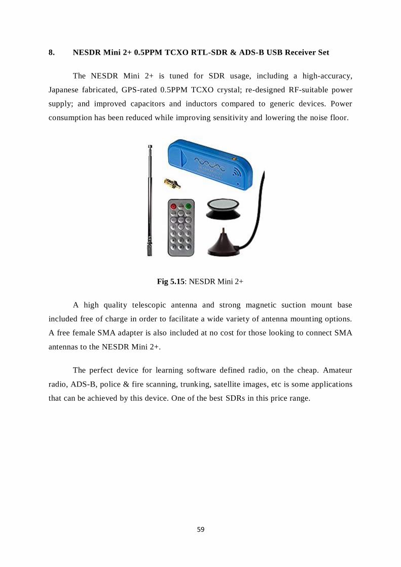
59
8. NESDR Mini 2+ 0.5PPM TCXO RTL-SDR & ADS-B USB Receiver Set
The NESDR Mini 2+ is tuned for SDR usage, including a high-accuracy,
Japanese fabricated, GPS-rated 0.5PPM TCXO crystal; re-designed RF-suitable power
supply; and improved capacitors and inductors compared to generic devices. Power
consumption has been reduced while improving sensitivity and lowering the noise floor.
Fig 5.15: NESDR Mini 2+
A high quality telescopic antenna and strong magnetic suction mount base
included free of charge in order to facilitate a wide variety of antenna mounting options.
A free female SMA adapter is also included at no cost for those looking to connect SMA
antennas to the NESDR Mini 2+.
The perfect device for learning software defined radio, on the cheap. Amateur
radio, ADS-B, police & fire scanning, trunking, satellite images, etc is some applications
that can be achieved by this device. One of the best SDRs in this price range.

60
9. RTL-SDR Blog R820T2 RTL2832U 1PPM TCXO SMA SDR
Fig 5.16: RTL SDR
This is an RTL-SDR software defined radio receiver with RTL2832U ADC chip,
1PPM TCXO, SMA F connector, R820T2 tuner and Aluminium case with passive
cooling. It tunes from 500 kHz to 1.7 GHz with up to 3.2 MHz (2.4 MHz stable) of
instantaneous bandwidth. (HF mode works in direct sampling mode - V3 models and
above only) and is perfect for use as a computer based radio scanner with free software
like SDR#, HDSDR, SDR-Radio, Linrad, GQRX or SDR Touch on Android. Works on
Windows, MacOS, Linux, Android and even embedded Linux computers like the
Raspberry Pi.
Great for many applications including general radio scanning, air traffic control,
public safety radio, ADS-B aircraft radar, AIS boat radar, ACARS, trunked radio,
P25/MotoTRBO digital voice, POCSAG, weather balloons, APRS, NOAA APT weather
satellites, Meteor M2 satellites, radio astronomy, meteor scatter monitoring, DAB, or for
use as a low cost PAN adapter with a traditional HAM radio.
This model has several improvements over other models. It uses the improved
R820T2 tuner, comes with a 1PPM TCXO (no drift and accurate tuning with a 2 PPM
initial offset and 1 PPM temperature drift), improved component tolerances, redesigned
PCB, cooling improvements, extra ESD protection and an SMA F connector. It also
comes with a software that can activate bias-tee circuit for powering external devices
such as LNA's and active antennas.

61
10. Ham It Up v1.3 - NooElec RF Upconverter For SDR
Fig 5.17: Ham IT Up Ver 1.3
While not a stand-alone SDR, this one made our list anyways. The Ham It Up
Upconverter works with the most common SDR platforms to create a HAM radio.
Ham/amateur radio enthusiasts, rejoice! Our MF/HF converter for software
defined radio will allow you to listen to MF and HF through your existing software
defined radio (SDR).
Improvements include increased sensitivity, ultra-low voltage noise floor,
optional battery-powered operation, side-mounted LED indicators, fully-assembled
broadband RF noise-source circuit, u.fl socket for optional external clock injection,
surface-mount high-accuracy oscillator and much, much more.
11. NESDR Nano 2+ Tiny Black RTL-SDR USB Set
The NESDR Nano 2+ are custom-made by NooElec for SDR applications. The
enclosure was also re-designed to assist in maintaining lower temperatures than the
previous generation.
Fig 5.18: NESDR Nano 2+

62
The tiny size and 24/7 capability makes the Nano 2+ perfect for embedded
applications. Its size is just 24mm x 21mm x 8mm (15/16" x 13/16" x 5/16")
The Nano 2+ contains a new custom TCXO fabricated exclusively for NooElec.
Important TCXO specifications: Frequency stability: 0.5PPM (max) Phase noise @1kHz
offset: -138dBc/Hz (or better) Phase noise @10kHz: -150dBc/Hz (or better) Phase noise
@100kHz: -152dBc/Hz (or better) This is, by far, the highest performance
TCXO available in any low-cost SDR.
Full compatibility with a wide variety of popular SDR software packages, such as
MatLab, HDSDR, SDR Touch, Planeplotter, SDR#, etc. whether Windows, Mac, Linux,
Android, Raspberry Pi.

63
CHAPTER 6
STUDY ON srsLTE PLATFORM
6.1 OVERVIEW
srsLTE is a free and open-source 4G LTE software suite. Using srsLTE, you can build
an end-to-end software radio mobile network.
Fig 6.1: An srsLTE Network Diagram
The srsLTE suite includes:
- srsUE - a complete SDR LTE UE (User Equipment) application
- srsENB - a complete SDR LTE eNodeB (Basestation) application
- srsEPC - a light-weight LTE EPC (Core Network) implementation with MME, HSS and
S/P-GW
All srsLTE software runs in linux with off-the-shelf compute and radio hardware.
srsLTE initially started with the release 001.001.000 with only support for BladeRF. Over a
period of time, the platform introduced multiple releases with support for almost all major
SDRs, the latest being the Release 20.04.1which was released in Mar 2020. We started our
project with Release 18.06 which has support for BladeRF, LimeSDR, Hackf, Soapy SDR,
UHD(USRP) and finally graduated to Release 19.6.0 which was released in 30 Jul 2019. The
basic features of the Releases are listed as under.

64
a) 20.04.1
- Fix for UE MIMO segfault issue
- Fix for eNodeB SR configuration
- Clang compilation warning fixes
- Fix GPS tracking synchronization
b) 20.04
- Carrier Aggregation and Time Alignment in srsENB
- Complete Sidelink PHY layer (all transmission modes)
- Complete NB-IoT PHY downlink signals
- New S1AP packing/unpacking library
- EVM and EPRE measurements
- Remove system timers in srsUE and srsENB
- Refactor eNB to prepare for mobility support
- Other bug-fixes and improved stability and performance in all parts
c) 19.12
- Add 5G NR RRC and NGAP ASN1 packing/unpacking
- Add sync routines and broadcast channel for Sidelink
- Add cell search and MIB decoder for NB-IoT
- Add PDCP discard
- Improve RRC Reestablishment handling
- Improve RRC cell measurements and procedure handling
- Add multi-carrier and MIMO support to ZMQ radio
- Refactor eNB scheduler to support multiple carriers
- Apply clang-format style on entire code base
- Other bug-fixes and improved stability and performance in all parts
d) 19.09
- Add initial support for NR in MAC/RLC/PDCP
- Add sync code for NB-IoT
- Add support for EIA3/EEA3 (i.e. ZUC)
- Add support for CSFB in srsENB
- Add adaptation layer to run TTCN-3 conformance tests for srsUE
- Add High Speed Train model to channel simulator
- Rework RRC and NAS layer and make them non-blocking
- Fixes in ZMQ, bladeRF and Soapy RF modules

65
- Other bug-fixes and improved stability and performance in all parts
e) 19.06
- Add QAM256 support in srsUE
- Add QoS support in srsUE
- Add UL channel emulator
- Refactor UE and eNB architecture
- Many bug-fixes and improved stability and performance in all parts
f) 19.03
- PHY library refactor
- TDD support for srsUE
- Carrier Aggregation support for srsUE
- Paging support for srsENB and srsEPC
- User-plane encryption for srsENB
- Channel simulator for EPA, EVA, and ETU 3GPP channels
- ZeroMQ-based fake RF driver for I/Q over IPC/network
- Many bug-fixes and improved stability and performance in all parts
g) 18.12
- Add new RRC ASN1 message pack/unpack library
- Refactor EPC and add encryption support
- Add IPv6 support to srsUE
- Fixed compilation issue for ARM and AVX512
- Add clang-format file
- Many bug-fixes and improved stability and performance in all parts
h) 18.09
- Improved Turbo Decoder performance
- Configurable SGi interface name and M1U params
- Support for GPTU echo mechanism
- Added UE detach capability
- Refactor RLC/PDCP classes
- Various fixes for ARM-based devices
- Added support for bladeRF 2.0 micro
- Many bug-fixes and improved stability and performance in all parts
i) 18.06.1
- Fixed RLC reestablish

66
- Fixed aperiodic QCI retx
- Fixed eNB instability
- Fixed Debian packaging
j) 18.06
- Added eMBMS support in srsUE/srsENB/srsEPC
- Added support for hard SIM cards
- Many bug-fixes and improved stability and performance in all parts
k) 18.03.1
- Fixed compilation for NEON
- Fixed logging and RLC AM issue
l) 18.03
- Many bug-fixes and improved stability and performance in all parts
m) 17.12
- Added support for MIMO 2x2 in srsENB (i.e. TM3/TM4)
- Added srsEPC, a light-weight core network implementation
- Added support for X2/S1 handover in srsUE
- Added support for user-plane encryption in srsUE
- Many bug-fixes and improved stability and performance in srsUE/srsENB
n) 17.09
- Added MIMO 2x2 in the PHY layer and srsUE (i.e. TM3/TM4)
- eMBMS support in the PHY layer
- Many bug-fixes and improved stability and performance in srsUE/srsENB
o) 002.000.000
- Added fully functional srsENB to srsLTE code
- Merged srsUE code into srsLTE and reestructured PHY code
- Added support for SoapySDR devices (eg LimeSDR)
- Fixed issues in RLC AM
- Added support for NEON and AVX in many kernels and Viterbi decoder
- Added support for CPU affinity
- Other minor bug-fixes and new features
p) 001.004.000
- Fixed issue in rv for format1C causing incorrect SIB1 decoding in some
networks
- Improved PDCCH decoding BER (fixed incorrect trellis initialization)

67
- Improved PUCCH RX performance
q) 001.003.000
- Bugfixes:
i. x300 master clock rate
ii. PHICH: fixed bug causing more NACKs
iii. PBCH: fixed bug in encoding function
iv. channel estimation: fixed issue in time interpolation
v. DCI: Fixed bug in Format1A packing
vi. DCI: Fixed bug in Format1C for RA-RNTI
vii. DCI: Fixed overflow in MIMO formats
- Improvements:
i. Changed and cleaned DCI blind search API
ii. Added eNodeB PHY processing functions
r) 001.002.000
- Bugfixes:
i. Estimation of extrapolated of out-of-band carriers
ii. PDCCH REG interleaving for certain cell IDs
iii. MIB decoding
iv. Overflow in viterbi in PBCH
- Improvements:
i. Synchronization in long multipath channels
ii. Better calibration of synchronization and estimation
iii. Averaging in channel estimation
iv. Improved 2-port diversity decoding
s) 001.001.000
- Added support for BladeRF
The srsenb, srsepc and srsue are described in detail in the succeeding paras.

68
6.2 srsENB
srsENB is an LTE eNodeB base station implemented entirely in software. Running as
an application on a standard Linux-based operating system, srsENB connects to any LTE
core network (EPC) and creates a local LTE cell. To transmit and receive radio signals over
the air, srsENB requires SDR hardware such as the Ettus Research USRP..
Features
The srsENB LTE eNodeB includes the following features:
• LTE Release 10 aligned
• FDD configuration
• Tested bandwidths: 1.4, 3, 5, 10, 15 and 20 MHz
• Transmission mode 1 (single antenna), 2 (transmit diversity), 3 (CCD) and 4 (closed-
loop spatial multiplexing)
• Frequency-based ZF and MMSE equalizer
• Evolved multimedia broadcast and multicast service (eMBMS)
• Highly optimized Turbo Decoder available in Intel SSE4.1/AVX2 (+100 Mbps) and
standard C (+25 Mbps)
• MAC, RLC, PDCP, RRC, NAS, S1AP and GW layers
• Detailed log system with per-layer log levels and hex dumps
• MAC layer wireshark packet capture
• Command-line trace metrics
• Detailed input configuration files
• Channel simulator for EPA, EVA, and ETU 3GPP channels
• ZeroMQ-based fake RF driver for I/Q over IPC/network
• Round Robin MAC scheduler with FAPI-like C++ API
• SR support
• Periodic and Aperiodic CQI feedback support
• Standard S1AP and GTP-U interfaces to the Core Network
• 150 Mbps DL in 20 MHz MIMO TM3/TM4 with commercial UEs
• 75 Mbps DL in SISO configuration with commercial UEs
• 50 Mbps UL in 20 MHz with commercial UEs
• User-plane encryption

69
eNodeB Architecture
The srsENB application includes layers 1, 2 and 3 as shown in the figure above. At
the bottom of the protocol stack, the Physical (PHY) layer carries all information from the
MAC over the air interface. It is responsible for link adaptation and power control.
Fig 6.2: Basic eNodeB Architecture
The Medium Access Control (MAC) layer multiplexes data between one or more
logical channels into Transport Blocks (TBs) which are passed to/from the PHY layer. The
MAC is responsible for scheduling uplink and downlink transmissions for connected UEs via
control signalling, retransmission and error correction (HARQ) and priority handling between
logical channels.
The Radio Link Control (RLC) layer can operate in one of three modes: Transparent
Mode (TM), Unacknowledged Mode (UM) and Acknowledged Mode (AM). The RLC
manages multiple logical channels or bearers for each con- nected UE. Each bearer operates
in one of these three modes. Transparent Mode bearers simply pass data through the RLC.
Unacknowledged Mode bearers perform concatenation, segmentation and reassembly of data
units, reordering and duplication detection. Acknowledged Mode bearers additionally
perform retransmission of missing data units and resegmentation.
The Packet Data Convergence Protocol (PDCP) layer is responsible for ciphering of
control and data plane traffic, integrity protection of control plane traffic, duplicate discarding
and in-sequence delivery of control and data plane traffic to/from the RRC and GTP-U layers

70
respectively. The PDCP layer also performs header compression (ROHC) of IP data if
supported.
The Radio Resource Control (RRC) layer manages control plane exchanges between
the eNodeB and connected UEs. It generates the System Information Blocks (SIBs) broadcast
by the eNodeB and handles the establishment, mainte- nance and release of RRC connections
with the UEs. The RRC also manages security functions for ciphering and integrity protection
between the eNodeB and UEs.
Above the RRC, the S1 Application Protocol (S1-AP) layer provides the control plane
connection between the eNodeB and the core network (EPC). The S1-AP connects to the
Mobility Management Entity (MME) in the core network.
Messages from the MME to UEs are forwarded by S1-AP to the RRC layer, where
they are encapsulated in RRC messages and sent down the stack for transmission. Messages
from UEs to the MME are similarly encapsulated by the UE RRC and extracted at the
eNodeB RRC before being passed to the S1-AP and on to the MME.
The GPRS Tunnelling Protocol User Plane (GTP-U) layer within srsENB provides
the data plane connection between the eNodeB and the core network (EPC). The GTP-U
layer connects to the Serving Gateway (S-GW) in the core network. Data plane IP traffic is
encapsulated in GTP packets at the GTP-U layer and these GTP packets are tunneled through
the EPC. That IP traffic is extracted from the tunnel at the Packet Data Network Gateway (P-
GW) and passed out into the internet.
6.3 srsEPC
srsEPC is a lightweight implementation of a complete LTE core network (EPC). The
srsEPC application runs as a single binary but provides the key EPC components of Home
Subscriber Service (HSS), Mobility Management Entity (MME), Service Gateway (S-GW)
and Packet Data Network Gateway (P-GW).

71
Fig 6.3: EPC Overall Architecture
The figure above illustrates the main components of the EPC, along with the main
interfaces between them.
a) HSS: The Home Subscriber Service (HSS) is the user database. It stores
information such as the user’s id, key, usage limits, etc. It is responsible for
authenticating an authorizing the user’s access to the network.
b) MME: Mobility Managment Entity (MME) is the main control element in the
network. It handles mobility and attach control messages. It is also responsible for
paging UEs in idle mode.
c) S-GW: The S-GW is the main dataplane gateway for the users, as it provides the
mobility anchor for the UEs. It works as an IP router and helps setting up GTP
sessions between the eNB and the P-GW.
d) P-GW: The Packet Gateway (P-GW) is the point of contact with external
networks. It enforces the QoS param- eters for subscriber sessions.
Features
The srsEPC LTE core network includes the implementation of the MME, HSS and
SPGW entities. The features of each of these entities is furthered described below.
MME Features
The srsEPC MME entity provides support for standard compliant NAS and S1AP
protocols to provide control plane communication between the EPC and the UEs and eNBs.
At the NAS level, this includes:
- Attach procedure, detach procedure, service request procedure
- NAS Security Mode Command, Identity request/response, authentication

72
- Support for the setup of integrity protection (EIA1 and EIA2) and ciphering (EEA0,
EEA1 and EEA2) At the S1AP level, this includes:
- S1-MME Setup/Tear-down
- Transport of NAS messages
- Context setup/release procedures
- Paging procedures
HSS Features
The srsEPC HSS entity provides support for configuring UE’s authentication
parameters and other parameters that can be configured on a per-UE basis. The HSS entity
includes the following features:
- Simple CSV based database
- XOR and MILENAGE authentication algorithms, specified per UE.
- QCI information
- Dynamic or static IP configuration of UEs
SPGW Features
The srsEPC SPGW entity provides support for to user plane communication between
the EPC and the and eNBs, using S1-U and SGi interfaces.
The SPGW supports the following features:
- SGi interface exposed as a virtual network interface (TUN device)
- SGi < > S1-U Forwarding using standard compliant GTP-U protocol
- Support of GTP-C procedures to setup/teardown GTP-U tunnels
- Support for Downlink Data Notification procedures
6.4 srsUE
srsUE is an LTE UE modem implemented entirely in software. Running as an
application on a standard Linux-based operating system, srsUE connects to any LTE network
and provides a standard network interface with high-speed mobile connectivity. To transmit
and receive radio signals over the air, srsUE requires SDR hardware such as the Ettus
Research USRP.

73
Features
The srsUE LTE UE includes the following features:
- LTE Release 10 aligned with features up to release 15
- TDD and FDD configurations
- Tested bandwidths: 1.4, 3, 5, 10, 15 and 20 MHz
- Transmission modes 1 (single antenna), 2 (transmit diversity), 3 (CCD) and 4 (closed-
loop spatial multiplexing)
- Manually configurable DL/UL carrier frequencies
- Soft USIM supporting XOR/Milenage authentication
- Hard USIM support via PC/SC
- Snow3G and AES integrity/ciphering support
- TUN virtual network kernel interface integration for Linux OS
- Detailed log system with per-layer log levels and hex dumps
- MAC and NAS layer wireshark packet captures
- Command-line trace metrics
- Detailed input configuration files
- Evolved multimedia broadcast and multicast service (eMBMS)
- Frequency-based ZF and MMSE equalizers
- Highly optimized Turbo Decoder available in Intel SSE4.1/AVX2 (+100 Mbps) and
standard C (+25 Mbps)
- Supports Ettus USRP B2x0/X3x0 families, BladeRF, LimeSDR
UE architecture
Fig 6.4: Basic UE Architecture

74
The srsUE application includes layers 1, 2 and 3 as shown in the figure above.
At the bottom of the UE protocol stack, the Physical (PHY) layer carries all
information from the MAC over the air interface. It is responsible for link adaptation, power
control, cell search and cell measurement.
The Medium Access Control (MAC) layer multiplexes data between one or more
logical channels into Transport Blocks (TBs) which are passed to/from the PHY layer. The
MAC is responsible for control and scheduling informa- tion exchange with the eNodeB,
retransmission and error correction (HARQ) and priority handling between logical channels.
The Radio Link Control (RLC) layer can operate in one of three modes: Transparent
Mode (TM), Unacknowledged Mode (UM) and Acknowledged Mode (AM). The RLC
manages multiple logical channels or bearers, each of which operates in one of these three
modes. Transparent Mode bearers simply pass data through the RLC. Unacknowledged Mode
bearers perform concatenation, segmentation and reassembly of data units, reordering and
duplication detection. Acknowledged Mode bearers additionally perform retransmission of
missing data units and resegmentation.
The Packet Data Convergence Protocol (PDCP) layer is responsible for ciphering of
control and data plane traffic, integrity protection of control plane traffic, duplicate discarding
and in-sequence delivery of control and data plane traffic to/from the RRC and GW layers
respectively. The PDCP layer also performs header compression (ROHC) of IP data if
supported.
The Radio Resource Control (RRC) layer manages control plane exchanges between
the UE and the eNodeB. It uses System Information broadcast by the network to configure
the lower layers of the UE and handles the establishment, maintenance and release of the
RRC connection with the eNodeB. The RRC manages cell search to support cell selection as
well as cell measurement reporting and mobility control for handover between neighbouring
cells. The RRC is also responsible for handling and responding to paging messages from the
network. Finally, the RRC manages security functions for key management and the
establishment, configuration, maintenance and release of radio bearers.
The Non-Access Stratum (NAS) layer manages control plane exchanges between the
UE and entities within the core network (EPC). It controls PLMN selection and manages

75
network attachment procedures, exchanging identification and authentication information
with the EPC. The NAS is responsible for establishing and maintaining IP connectivity
between the UE and the PDN gateway within the EPC.
The Gateway (GW) layer within srsUE is responsible for the creation and
maintenance of the TUN virtual network kernel interface, simulating a network layer device
within the Linux operating system. The GW layer permits srsUE to run as a user-space
application and operates with data plane IP packets
NOTE
The detailed Deployment of the srsLTE network is given out in the next cgapter.
The srsUE is also installed in the PC. Though we are using commercial smartphones
(Motorola G3 model) along with USIM cards for the project. We can check up with the
mobile devices for the LTE bands that they support and change the network
parameters as per our requirements.

76
CHAPTER 7
INSTALLATION AND PERFORMANCE ANALYSIS WITH KEY RESULTS
7.1 MODULES REQUIRED
1. SDRs. After a thorough study, we have homed on to use of both BladeRF X40
and USRP B210. Both the SDRs were readily available and are light weight and cost
effective.
2. Small Form Factor PC. It is decided to use Odroid XU4 and main PC for
trial. As minimum requirement of RAM was 4GB, it was agreed that we purchase
Intel NUC SBC and/or Raspberry Pi 4B 4GB Rev 1.2. All the trials were carried out
successfully in a normal PC in laboratory environment as well as in Odroid XU4.
3. Micro SD card and card reader for complete setup in Odroid and Raspberry
Pi.
4. Power. We are using 12V, 1300mah battery along with a BLE for power
requirements.
7.2 SETTING UP PC/SBC
1. The latest version of linux can be downloaded from
https://wiki.odroid.com/odroid-xu4/os_images/linux/start i.e. UbuntuMate 18.04.
2. Burn the OS image files into an SD card with 16/32GB memory from another
PC.
3. Boot up the PC/SBC with Ubuntu 18.04 or higher.
4. Upgrade the firmwares and libraries
sudo apt-get update
sudo apt-get upgrade
5. It is mandatory that the system is connected to internet while updating and
upgrading the OS to the latest version.

77
7.3 SETTING UP SDRs
1. Installation Of USRP B210 Drivers(UHD)
sudo add-apt-repository ppa:ettusresearch/uhd
sudo apt-get update
sudo apt-get install libuhd-dev libuhd003 uhd-host
sudo uhd_images_downloader
2. Installation Of BladeRF Softwares
sudo apt install git apache2 php
sudo apt install bladerf bladerf-firmware-fx3 bladerf-fpga-hostedx40 libbladerf1 automake libbladerf-dev
7.4 INSTALLATION OF srsLTE
sudo apt install cmake libfftw3-dev libmbedtls-dev libboost-program-options-dev libconfig++ -dev libsctp-dev
git clone https://github.com/srsLTE/srsLTE.git
cd srsLTE
mkdir build
cd build
cmake ../
make
make test
sudo make install
srslte_install_configs.sh user
sudo ldconfig
7.5 ENABLING THE BACKHAND INTERNET CONNECTIVITY TO THE EPC
sudo srsepc_if_masq <out_interface>
NOTE: Here network interface is the name of the interface on which the PC is connected to
the internet. It can be ascertained by running the code below:-
sudo ip link show

78
NOTE: In order to make sure that eNodeB and EPC both are install, we may run
the codes below
sudo apt install srsenb
sudo apt install srsepc
7.6 CONFIGURE ENB AND EPC
cp srsenb/enb.conf.example srsenb/enb.conf
cp srsenb/rr.conf.example srsenb/rr.conf
cp srsenb/sib.conf.example srsenb/sib.conf
cp srsenb/drb.conf.example srsenb/drb.conf
cp srsepc/epc.conf.example srsepc/epc.conf
srsepc/user_db.csv.example srsepc/user_db.csv
7.7 PARAMETERS SETTING FOR NETWORK
1. Open the eNodeB configuration file with name enb.conf using the command
below and set the value of transmission parameters.
sudo gedit enb.conf
set the following values:
dl_earfcn
tx_gain
rx_gain
mcc
mnc
2. After changing the parameters, open the epc.conf file and set the same mcc
and mnc values as in enb.conf
3. Now open user_db_csv file and edit the user parameters that are being
configured in USIM cards. For multiple USIM cards, set multiple entries
corresponding to each USIM cards (see para 7.8)
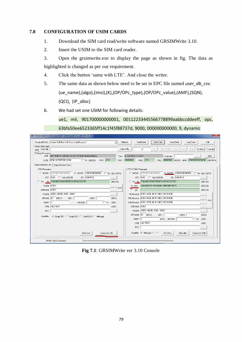
79
7.8 CONFIGURATION OF USIM CARDS
1. Download the SIM card read/write software named GRSIMWrite 3.10.
2. Insert the USIM to the SIM card reader.
3. Open the grsimwrite.exe to display the page as shown in fig. The data as
highlighted is changed as per our requirement.
4. Click the button ‘same with LTE’. And close the writer.
5. The same data as shown below need to be set in EPC file named user_db_csv.
(ue_name),(algo),(imsi),(K),(OP/OPc_type),(OP/OPc_value),(AMF),(SQN),
(QCI), (IP_alloc)
6. We had set one USIM for following details:
ue1, mil, 901700000000001, 00112233445566778899aabbccddeeff, opc,
63bfa50ee6523365ff14c1f45f88737d, 9000, 000000000000, 9, dynamic
Fig 7.1: GRSIMWrite ver 3.10 Console

80
7.9 STARTING THE NETWORK
sudo srsepc
sudo srsenb
The following are the screenshots of the network trial carried out at lab. The trial was carried outin both normal PC as well as Odroid XU4. The various network and user setting datawill be available in the screenshot below.
Fig 7.2: EPC Console
Fig 7.3: eNB Console

81
Fig 7.4: ENB Started and linked to EPC
Fig 7.5: User Data Transmission over eNB Console

82
Trial On Odroid XU4
Fig 7.6: EPC and eNB Consoles
Fig 7.7: EPC and eNB Data Transmission Showing Buffer Data in Consoles

83
Spectrum Analyser Data
Fig 7.8: Transmitting 4G signals at frequency of 869 MHz and10 MHz Bandwidth in USRP B210
Fig 7.9: Transmitting 4G signals at frequency of 869 MHz and10 MHz Bandwidth in BladeRF x40

84
Fig 7.10: 4G Mobile connectivity of the service with name MTECH Project in Motorola G3
Fig 7.11: Network setup using Odroid XU4 with USRP B210 and BladeRF X40

85
----Signal--------------DL-------------------------------------UL---------------------
˓→-
cc rsrp
˓→bler
pl cfo mcs snr turbo brate bler ta_us mcs buff brate
7.10 PERFORMANCE METRIC EVALUATED
1. RF configuration
dl_earfcn: EARFCN code for DL
tx_gain: Transmit gain (dB).
rx_gain: Optional receive gain (dB). If disabled, AGC if enabled
Value set in our network
dl_earfcn = 3400
tx_gain = 80
rx_gain = 40
0 -77 77 1.2k 24 33 0.84 5.8M 0% 0.0 18 193k 624k 0%
0 -77 77 1.2k 24 31 0.80 5.7M 0% 0.0 18 193k 631k 0%
0 -77 77 1.2k 24 32 0.80 5.8M 0% 0.0 18 192k 633k 0%
0 -77 77 1.2k 25 34 0.93 6.0M 0% 0.0 18 194k 636k 0%
0 -77 77 1.2k 24 33 0.83 5.8M 0% 0.0 19 193k 632k 0%
0 -77 77 1.2k 24 31 0.82 5.8M 0% 0.0 18 194k 632k 0%
0 -77 77 1.2k 24 32 0.82 5.8M 0% 0.0 18 193k 635k 0%
0 -77 77 1.2k 25 34 0.91 6.0M 0% 0.0 18 194k 629k 0%
0 -77 77 1.2k 24 33 0.85 5.8M 0% 0.0 19 193k 634k 0%
0 -77 77 1.2k 24 31 0.82 5.7M 0% 0.0 19 194k 647k 0%
0 -77 77 1.2k 24 32 0.84 5.8M 0% 0.0 18 192k 629k 0%
Fig 7.12: Example of Metric Trace of the srsLTE Network
Metrics are generated once per second by default. This can be configured using the
expert.metrics_period_secs parameter in ue.conf. Metrics are provided for the received signal
(Signal), downlink (DL) and uplink (UL) respectively. The following metrics are provided:
- mcs: Modulation and coding scheme (0-28)
- snr: Signal-to-Noise Ratio (dB)
- turbo: Average number of turbo decoder iterations
- brate: Bitrate (bits/sec) bler Block error rate
- ta_us: Time advance (uS)
- buff: Uplink buffer status - data waiting to be transmitted (bytes)

86
- cc: Component carrier
- rsrp: Reference Signal Receive Power (dBm)
- pl: Pathloss (dB)
- cfo: Carrier Frequency Offset (Hz)

87
CHAPTER 8
KEY RESULTS AND SUMMARY
As seen clearly from the previous chapter, it is seen that a 4G/LTE network can be
established using the srsLTE platform. The network can be customized as per the need of the
organization or agency using it. Moreover, it is important to study that which smartphone
brands support which LTE band.
Most of the budget phones do not support FDD B7 band which we had configured
which has EARFCN value of 3400. The downlink frequency is 2.685GHz and uplink
frequency is 2.565GHz, which is commercially not being used elsewhere and hence proven to
be interference free band of frequencies, Though modification can be made to the eNB by
changing the RF parameters of the enb.conf file as per our needs to any frequency region as
well as power levels and channels.
The established network supported VoIP services as of now. So, an IMS server can
also be integrated in future for number to number calling. Presently, the users are being
authenticated connection to the network eNB by their IMSI number which have been
configured both in USIM card and EPC parameters in epc.conf file and stored in user_db_csv
file also.

88
CHAPTER 9
PAPER STUDY ON SPETRUM SENSING ALGORITHMS
9.1 SUMMARY ON PAPERS ON SPECTRUM SENSING
All the eight papers give detailed highlights of the Spectrum Sensing algorithms for
Wideband Spectrum Sensing, starting from the basic energy sensing to advanced sub-
nyquist Wide Band compressive Sensing and SweepSensing algorithms, the details of each
of them are presented below.
PAPER 1: Simple and Low-Cost Platforms for Cognitive Radio Experiments
(a) Written by Alexander R. Young and Charles Bostian
(b) The Article deals with the CR architecture in which RF ASIC on a chip can
replace the usual SDR of a CR, thereby reducing the radio cost, computationally
complexity and size.
(c) Basic emphasis was given on the reduction in SDR platform wherein the
system can have computational platform (CE and DSP functions) and Radio Platform
(for RF functions) only rather than the complete SDR setup.
(d) Basic algorithm followed is Energy Detection and uses Listen-Before-Talk
Protocol.
(e) The paper is demonstration for Dynamic Spectrum Access.
(f) The main advantage of the proposed replacement is the reduction in size and
weight, suitable to be carried by a drone or a UAV.
Paper 2: Wideband Spectrum Sensing for Cognitive Radio Network: A Survey
(a) By Hongjian Sun, Arumugam Nallanathan, Cheng-Xiang Wang, Yunfei Chen
(b) The paper basically deals with the advantages of WideBand Spectrum
Sensing, with the limitations paused by frequency selective narrow band or single
band sensing.
(c) Various WB sensing algorithms are discussed in the paper, giving the
advantages and disadvantages of each of the algorithms.
(d) Special emphasis is delegated to Sub-Nyquist Sensing techniques for it
added pros (Compressive Sensing, Multichannel Sub-Nyquist Sampling Techniques,
etc)

89
(e) Moreover, it also mentions the future challenges in Sensing and spectrum
utilisation techniques to include Adaptive WideBand Sensing and Co-operative
Sensing techniques.
Paper 3: A Survey of Spectrum Sensing Algorithms for CR Applications
(a) By Tevfik Yucek and Huseyin Arslan
(b) The paper presents basic sensing algorithms and their pros and cons.
(c) It then gives the aspect of extension of dimensions of sensing. Although
generic spectrum sensing algorithms traditionally are being understood as measuring
the spectrum usage characteristics only. Here, spectrum usage is studied in multiple
dimensions like time, space, codes, etc.
(d) The article presents theoretical Hyperspace which has location, Angle of
Arrivals, beam forming, frequency, time, errors, etc. and also termed as Electro
space.
(e) Moreover, it also discusses Single Radio Sensing Architecture and Dual
Radio Sensing Architecture.
(f) Some challenges faced for Multidimensional Sensing are also discussed.
Cooperative Sensing both centralized and distributed techniques are also being
made a mention.
(g) Basically, the paper presents a theoretical aspects of various sensing
techniques and their pros and cons.
Paper 4: Compressed WB Spectrum Sensing: Concept, Challenges and Enablers
(a) By Bechir Hamdaoui, Bassem Khalfi and Mohsen Guizani
(b) This paper deals mainly to the concept of Compressed Spectrum Sensing
algorithms. It gives some cons of the uncompressed sensing techniques, followed by
the Sub-Nyquist Compressive Sensing for WideBand sensing.
(c) The idea of Sparsity in matrices is considered here.
(d) Moreover, concept of Weighted Compressive Sensing Technique is
introduced to improve the recovery efficiency. Here, applications of similar types are
assigned a spectrum block, within the same frequency blocks as we know that
different frequency blocks exhibit different occupancy statistics. Weights are assigned
to blocks with some Sparsity (i.e. blocks with higher sparsity assigned lower weights).
90
(e) It also gives the overview of Adaptive and Cooperative Compressed
Spectrum Sensing and also presents some open research challenges.
Paper 5: WideBand Spectrum Sensing with Sub-Nyquist Sampling in Cognitive
Radios
(a) By Hongjian Sun, Arumugam Nallanathan, Wei-Yu Chiu, Jing Jiang and H.
Vincent Poor.
(b) It deals with Multirate Asynchronous Sub-Nyquist Sampling (MASS)
technique for wideband spectrum sensing.
(c) It uses basic Energy detection sensing technique, but applied to wideband
filter, which is subdivided into wavelets. Each wavelets is detected using Filter banks
using multiband joint detection with each filter banks occupying varied frequencies.
The sampled data are detected using FFT and the entire spectrum is reconstructed.
The Reconstructed energy is detected based on threshold detection technique.
(d) Here, sampling is done Sub-Nyquist following some given mathematical
criteria so as to have low probability of overlap.
(e) The study is also being simulated in the paper.
Paper 6: Dynamic Compressive Spectrum Sensing for Cognitive Radio Networks
(a) By Wotao Yin, Zaiwen Wen, Shuyi Li , Jia (Jasmine) Meng and Zhu Han
(b) The paper exhaustively deals with Compressive Sensing in details.
(c) It gives basic idea of collaborative compressive sensing technique and its
advantages over traditional sweeping of a set of channels sequentially. Here, sharing
of the sensed data is shared with the fusion centre for use by all other CRs.
(d) The paper explains different types of Compressive Sensing Algorithms like
the Static or Dynamic Compressive Sensing. It explains the basic signal models and
recovery method more extensively for dynamic techniques.
(e) Finally, a simulation model is presented along with performance analysis of
dynamic sensing.
Paper 7: Spectrum Sensing and Resource Allocation for Multicarrier Cognitive
Radio Systems Under Interference and Power Constraints
(a) By Sener Dikmese, Sudarshan Srinivasan, Misbah Shaat, Faouzi Bader and
Marku Renfors

91
(b) The paper claims to be the work of Spectrum Sensing and Resource
allocation together in a single algorithmic framework. Generally, most of the sensing
techniques either does spectrum sensing or does resource utilisation after sensing,
but not both.
(c) Here, the article presents algorithm for sensing spectrum using energy
detection technique (Filter Bank Based Wideband sensing), followed by algorithm for
optimal resource allocation in a single CR Networks.
(d) It gives the signal models of all the units (PU, SU, Noise and Interference,
etc) for Sensing. Use of Sub-band Energy detection followed by FFT or Analysis
Filter Bank method for detection and spectrum utilisation using Convex Optimisation
problem to the recovered signal details.
(e) Finally, it gives a simulation and analysis of the algorithm being discussed.
Paper 8: SweepSense: Sensing 5 GHz in 5 milliseconds with Low-cost Radios
(a) By Yeswanth Guddeti, Raghav Subbaraman, Moein Khazraee, Aaron
Schulman and Dinesh Bharadia.
(b) The paper presents the idea of SweepSense which gives a high time
resolution wide sensing using Off the Shelf Narrow Band radios.
(c) It gives the practical implementation framework using a simple NB radio to
sweep for wideband with high fidelity. Involves modification of SDR hardware, Verilog
programming and generation of saw tooth waveform to enable the radio to Sweep
over large bandwidth.
(d) It gives the step by step procedure of the implementation of SweepSense
along with practical application ideas liking Sweeping across the 4G band for LTE
channel utilisation.
(e) Advantages and limitations are also discussed along with challenges to come
while making a NB radio like URSP sweep across a band.
(f) It is altogether the combination of basic sensing technique followed by making
the sensing Sweep. By doing this, we achieve wideband sensing by using merely a
low-cost energy sensing CR radios.

92
CHAPTER 10
POTENTIAL EXTENSION AND FUTURE WORKS
10.1 POTENTIAL EXTENSION
Presently, the project aimed at provision of communication infrastructure to PPDR
Agencies, communication for military activities, for covering non-communication zone, etc.
The main aim/scope of the entire setup is the 4G/LTE based communication setup over aerial
platform, Drones or UAVs. But being portable in nature, the system gives various facets of
flexibilities for other application of future needs. Some of the probable extensions envisaged
are listed in the succeeding paragraphs.
a) Integration of Spectrum Sensing: The Spectrum Sensing algorithms can be
implemented in the same hardware or a different SDR (board only needed) and can be
mounted over. This extension may be utilized for studying various frequency transmission
nature of the area deployed. Further it can provide necessary spectrum utilization datas to the
existing communication infrastructure and hence the system can home on to unused
frequencies to avoid interference between the set network and other commercial
transmissions.
b) Integration of Jammers: The system can also include a jammer which can jam a
network which is causing disturbances during PPDR duties. Further, The whole system can
act as an independent “Detect-Avoid-Jam” 4G/LTE network which can itself analyse the
frequency occupancy and make necessary decision to enable interference free and robust
network architecture.
c) Secured Network for Military Grade Applications: Though the srsLTE has its own
encryption keys for securing traffic between eNB and User devices and the same can be used
as a communication network for military areas where mobile network is meager. Still
incorporation of a strong encryption algorithm can provide the network a grade of security
which will enable usage of the network for secured tactical military applications.

93
d) AI-Based Intelligent Scanner cum Communication System: The proliferation
of AI/ML has resulted into enhancement of several cognitive features of an SDR. The same
can be utilized for self-assessing system network.
e) 4G/LTE integration with Military Tactical network: Modules can be designed
which may act as the mediator system between the secured network of military with the
srsLTE network established. The military VHF/HF and Radio relay networks are the main
backbone in the tactical network system. Moreover, Indian Army units have deployed
military grade 4G network in various regions for their in-house communication. All these can
be proposed to integrate for seamless transmission.
f) 4G/LTE Based RADAR System: The concept of SweepSense has given
possibility that the SweepSense algorithm can scan through 5GHz band of frequencies in just
5 milliseconds time. This gives the sensor its RADAR capabilities and can detect the
frequency of any flying/transmitting network in milliseconds times. The sensed data may be
transmitted over using the 4G/LTE based backhaul network designed.
10.2 RECOMMENDATIONS FOR THE FUTURE WORK
a) Encryption Algorithm: A software based security system can be designed
which can be incorporated with the network for further robustness and reliability.
b) Configuration of IMS Server: An IMS server like that of Kamailo can be
integrated to allow number to number calling between subscribers. Presently, the network
established has strong data capability providing VoIP, internet services.
c) 5G Core With 4G EPC: Open Air Interface has given feasibilities of interfacing
5G core network with 4G EPC as backhaul connectivity. The system can be exploited using
srsLTE EPC and OAI 5G for purpose of study of 5G network.
d) Integration of AI, Spectrum Sensing, Jammer and a cross-Platform Module: As
mentioned earlier, a “Robust and Smart” device can be made out of the srsLTE based
network. This single device can act as a communication module, a sensor or a RADAR with
smart and Intelligent AI based Cognition.

94
e) 4G Mesh Network: Multiple 4G based srsLTE EPC can be interconnected to form a
mesh network. The network should IMS server and allow calling out of the eNB zone of one
node to another. This would enhance the network capabilities and range of the system.
f) Power Amplifier: A Small Power Amplifier can be identified which can enhance
the signal strength of the eNB. Presently the system works for a distance of about 150m. The
amplifier may be chosen and configured such that the range may be enhanced to the level of
the classical 4G commercial network, may be say 800-1000 meters.

95
CHAPTER 11
CONCLUSION
It has been ascertained that the PPDR and allied agencies need a robust and reliable
network for their normal functioning during any disaster or public protection work.
Moreover, India is abound of many black out areas where mobile networks are almost zero.
Hence, it is always needed that an ad-hoc network be ready for such situations. The srsLTE
provides a beautiful platform where one can develop a working 4G/LTE network which can
be easily used.
Moreover, military activities also need a good communication on the move. Hence,
the system with some encryption can be a best solution to the military equation.
There are some basic limitations which cropped up in the network which can also be
modified in future for further enhancements.
a) The srsLTE works in a particular band of LTE say FDD B7. So, selection of
smartphones becomes an important task to use the network as some may not support the
established network.
b) There is no backhaul connectivity with other EPCs, the solution for the problem nedds
an address. But backhaul data connectivity can be established by masquerading the network
address of the internet service that we provide.
c) Power limitations when on air. This problem can be resolved using tethered drones
where drones are powered by power from ground. But mobility restricted to the length of the
power cable here.
d) The range and limited power output of the SDR limits it to be covered for a distance
of about 150-200 metres. The range can be enhanced by using an amplifier.
Despite its limitation, a strong network over an aerial platform like drones would cater
for any exigency of the duties the PPDR agencies are undergoing. The mobility gives huge
added advantages over the static network. It’s easy to install and launch and are failproof
during any calamities. It can be carried and used as an ad-hoc network for various other
purposes too.

96
APPENDIX A: WEIGHTS OF VARIOUS HARDWARES AND
COMPPLETE SETUP
a) JioFi Dongle____________________ 100gms.
b) ODROID-XU4 ___________________ 90gms with fan (board only)
c) BladeRF _________________________273gms
d) Battery Eliminator Circuit ___________ 42 gms.
e) Bty (1300mAH)___________________125gms.
f) Bty (6200mAH) ___________________430gms.
g) Boxes and misc connections__________300gms
h) USRP B210_______________________350gms
So the set up with SBC+BladeRF will be approximately 1.36 kgs and the set up using
USRP B210 will be about 1.44 kgs. Both the load can be easily carried by a drone and hence
will facilitate smooth functioning on air.

97
APPENDIX B: SUBMISSION FOR ANVESHAN 2020
COMPETITION
DRONE-BASED 4G COMMUNICATION SYSTEM FOR PPDR VOICE AND VIDEO
APPLICATIONS
1. Introduction.
Two scenario wherein emergency communication are needed are natural
(hurricanes, floods etc) and manmade disasters (such as railway accidents) in order
to carry out the relief work. India is a country comprising of diverse weather
scenarios and the effects of the varied weather conditions are very well known. India
is highly prone to natural disasters like floods, earthquakes, coastal cyclones. Hence,
the country has taken up huge steps and measures to provide relief to the disaster
affected areas and the people. Various agencies work together to provide public
safety and disaster relief activities are in vogue throughout the year. Hence,
coordination between these agencies and the government bodies are a must.
During such events, there is sudden increase in communication traffics (voice,
video & data) in cellular network. The sudden increase in loads, in conjunction with
the failures due to natural/ man-made emergencies result into complete choking of
the network infrastructure, causing communication outages during such times.
The goal of this project is to provide a Droned-Based 4G Communication
system, which is quick and easy to establish and can be mobilised easily. The main
aim of the proposed system is to provide the PPDR Agencies Military/ para military/
medical team favourable working environment to carry out their intended relief work,
with full communication connectivity.
2. Detailed Problem Statement and Prescribed Solution.
Communication plays an important role in providing rescue and relief activities
during natural or man-made disasters, especially in highly prone countries like India.
Public Protection and Disaster Relief (PPDR) Agencies like Police, Fire, Paramedics,
Military, etc need strong and resilient communication networks for their emergency
and public safety operations. Hence, the effectiveness and efficiency of public
protection, safety and law enforcements pivots on the ROBUST and RELIABLE
COMMUNICATION INFRASTRUCTURE.
Thus, the proposed solution intends to develop a Communication System for
the PPDR applications, which can be deployed at the affected areas and can be
mobilised in a less than 30 mins so as to enhance the effectiveness and
communication of the PPDR teams.

98
The solution prototype will comprise of an SDR with the transceiver
configured as a 4G eNodeB and EPC, a small form factor computer for running the
SDR and power arrangements, housed in a box. The entire set up will be mounted
on a Drone for enhanced mobility and flexibility (typical flying height of drone 25-
50m).
Today the primary limitation of drone is their limited flying time. This issue will
be addressed by using a tethered drone with the tether providing power & data
connectivity thereby enabling the drone to fly for extended period (several hours).
Moreover, drone based 4G system will integrate video camera to enable
video/ image transfer. The drone will also have a spectrum sensing hardware to
detect the unused frequency to avoid interference.
Additionally, the proposed solution can also be implemented for the
following scenarios (with or without tether):-
(a) Tactical/ defence operations in border areas or in those areas where
there is complete blackout of the cellular communications networks
(b) With video feed capability of the drones, it can be used for search and
rescue operations of trapped survivors in inhospitable terrains. It can
also be used for video surveillance & reconnaissance.
3. Uniqueness of the project / Innovation
(a) The Indian PPDR agencies use narrow band digital trunking
technology like TETRA and P25 systems which are primarily meant for
voice communications, which are run by independent state agencies. This
results in inability to have seamless communication interoperability and
information sharing amongst the relief agencies/ workers.
(b) Being independent of one another, the communication devices of the
different agencies are not interoperable, or compatible to one another.
c) Major Uniqueness of the proposed solution is enumerated below:-
(i) Drone-based portable eNodeB stations to provide extended
coverage range of communication.
(ii) Voice, video and data capability using commercial 4G handsets.
(iii) Adequate power supply via tethered drone.
(iv) Only authorised PPDR workers can connect to the
communication network.
(v) Wide range of applicability in addition to PPDR activities; such
as tactical operations and temporary communication setup (hotspot
coverage during large religious festivals, rallies etc).

99
4. System or Concept level Block Diagram
5. What do you want to achieve on the project if you are selected?
If the project proposal is selected, then the following are the tasks that will be
planned for achievements during the period of six months given for the
development:-
(a) Development and configuration of the 4G eNodeB prototype of the
communication system as proposed.
(b) Testing in the laboratory and on ground using tethered drone.
6. What are your long term plans to take this project forward?
The following are amongst the brief aspects of future planning that will be
further followed by the team;-
(a) Development of the complete and workable design solution.
(b) Ruggedization of the complete setup for enhanced outdoor usage.
(c) Integration with the existing cellular infrastructure and service
providers.
(d) Transfer of technology to Industrial partner for product development.
7. What would be the possible Limitations of your proposed solution to the
problem?
(a) Drones are affected by heavy rains and strong winds.

100
(b) Some training is required to fly the drones and to keep in hovering
position.
(c) Must avoid collision with trees and foliage.
(d) Spectrum allocation for emergency commutation (our proposed
solution will use cognitive radios and white space detection to avoid
interference).
(e) Network Security and Privacy.
8. What Hardware, Software and Cloud platforms would you plan to use?
(a) A Software-Defined Radio with Transceiver module embedded within it.
(b) Small form factor single board computer
(c) Drones
(d) Tethered to supply power and data connectivity to drone
(e) 4G User Equipment (Smart Phones) and SIM cards
(f) Software programs for 4G eNodeB and light EPC
The functionalities of (a) and (b) can be developed using Analog Devices products
and evaluation platform.

101
APPENDIX C: UBUNTU CONFIGURATION AND SETUP
GUIDE FOR srsLTE
1. Installation of UHD
sudo add-apt-repository ppa:ettusresearch/uhd
sudo apt-get update
sudo apt-get install libuhd-dev libuhd003 uhd-host
sudo uhd_images_downloader
2. Installation of Library Packages
sudo apt-get install cmake libfftw3-dev libmbedtls-dev libboost-program-options-dev libconfig++-dev libsctp-dev
3. Installation of srsLTE
git clone https://github.com/srsLTE/srsLTE.git
cd srsLTE
mkdir build
cd build
cmake ../
make
make test
sudo make install
sudo srslte_install_configs.sh
sudo ldconfig
4. Connecting EPC with Backhaul Internet
sudo ip link show
sudo srsepc_if_masq <out_interface>
After running iplink show, note the network interface name which is to be used
in next line of command.
5. Running the srsLTE
sudo srsepc
sudo srsenb

102
REFERENCES
1. Yeswanth Guddeti, Raghav Subbaraman, IIT Madras, Moein Khazraee, Aaron
Schulman, and Dinesh Bharadia ,UC San Diego†IIT Madras. SweepSense: Sensing 5 GHz
in 5 Milliseconds with Low-Cost Radios.
2. srsLTE Documentation, Release 19.12.0, Release 18.06 and Release 20.04.1
3. Ismael Gomez-Miguelez, Andres Garcia-Saavedra, Paul D. Sutton,Pablo Serrano,
Cristina Cano, Douglas J. Leith. srsLTE: An Open-Source Platform for LTEEvolution and
Experimentation
4. Radu CURPEN, Vlad FERNOAGA, Dan ROBU and Florin SANDU, Department of
Electronics and Computers,Transilvania University,Brasov, Romania. Open-LTE Call
Emulator in Software Defined Radio (08909662_IEEE paper)
5. Naufal Alee, Mostafijur Rahman, R. B. Ahmad, Embedded Computing Research
Cluster (ECRC), School of Computer and Communication Engineering, Universiti Malaysia
Perlis. Performance Comparison of Single Board Computer : A Case Study of Kernel on
ARM Architecture
6. Travis F. Collins, Robin Getz, Di Pu, Alexander M. Wyglinski. Software-Defined
Radio for Engineers
7. FN-Division, Telecom Engineering Centre, K.L. Bhawan, Janpath, New Delhi. Public
Protection and Disaster Relief (PPDR) Communication System
8. Anxo Tato, AtlanTTic Research Center,University of Vigo, Spain. Software Defined
Radio: A Brief Introduction
9. Devarpita Sinha1, Anish Kumar Verma, Sanjay Kumar, Department of Electronics &
Communication Engineering, BIT Mesra, Ranchi, India. Software Defined Radio:
Operation, Challenges and Possible Solutions
10. The Telecom Regulatory Authority of India Press Release No. 61/2018 dated 4th
June, 2018. Next Generation Public Protection and Disaster Relief (PPDR) communication
networks

103
11. Telecom Regulatory Authority of India Consultation Paper No. 15/2017 dated 9th
October, 2017. Next Generation Public Protection and Disaster Relief (PPDR)
communication networks
12. Syed Ahsan Raza Naqvi, Syed Ali Hassan, Haris Pervaiz, and Qiang Ni. Drone-Aided
Communication as a Key Enabler for 5G and Resilient Public Safety Networks
13. Alexander R. Young and Charles W. Bostian. Simple and Low-Cost Platforms for
Cognitive Radio Experiments
14. Wotao Yin, Zaiwen Wen, Shuyi Li, Jia (Jasmine) Meng, and Zhu Han. Dynamic
Compressive Spectrum Sensing for Cognitive Radio Networks
15. Bechir Hamdaoui, Bassem Khalfi, and Mohsen Guizani. Compressed Wideband Spectrum
Sensing: Concept, Challenges, and Enablers