Embed Size (px)
Citation preview
Freescale SemiconductorApplication Note
Document Number: AN4037Rev. 0, 02/2010
Contents
Introduction . . . . . . . . . . . . . . . . . . . . . . . . . . . . . . . . . . . 1Stepper Motor Module . . . . . . . . . . . . . . . . . . . . . . . . . . . 2
2.1 Overview . . . . . . . . . . . . . . . . . . . . . . . . . . . . . . . . . 22.2 Stepper Motor Control . . . . . . . . . . . . . . . . . . . . . . . 32.3 Mode of Operations. . . . . . . . . . . . . . . . . . . . . . . . . 42.4 Creating Basic PWM Signals. . . . . . . . . . . . . . . . . . 52.5 Advanced PWM functions . . . . . . . . . . . . . . . . . . . . 72.6 Outputting the PWM signals . . . . . . . . . . . . . . . . . . 8Waveforms required to drive stepper motor . . . . . . . . . 10
3.1 Full Step . . . . . . . . . . . . . . . . . . . . . . . . . . . . . . . . 103.2 Microstepping . . . . . . . . . . . . . . . . . . . . . . . . . . . . 12Using SMC Module to create waveforms . . . . . . . . . . . 13
4.1 Program Structure . . . . . . . . . . . . . . . . . . . . . . . . . 154.2 Initialization . . . . . . . . . . . . . . . . . . . . . . . . . . . . . . 15Advanced Features . . . . . . . . . . . . . . . . . . . . . . . . . . . . 17
5.1 Short Circuit Detection. . . . . . . . . . . . . . . . . . . . . . 175.2 Stall Detection . . . . . . . . . . . . . . . . . . . . . . . . . . . . 18
Driving a Stepper Motor using the MPC56xxS SMC Moduleby: Daniel McKenna
Microcontroller Solutions Group. Auto R & D
1 IntroductionThe MPC56xxS microcontroller device is targeted at the cluster segment of the automotive market. The MCU as such has the capability to drive visual displays, generate sound and to drive the dials used for speedometers and tachometers. This application note provides details of how the latter is achieved by using the Stepper Motor Control (SMC) module.
The following section provides an overview of what a stepper motor is and the fundamental principles of how it operates. This is followed by an overview of the SMC module and a discussion on the waveforms required to drive a stepper motor.
The example application code in AN4037SW provides details of how the SMC can be used to generate these waveforms.
12
3
4
5
© Freescale Semiconductor, Inc., 2010 All rights reserved.
Stepper Motor Module
2 Stepper Motor Module
2.1 OverviewAs the name suggests, a stepper motor is a motor whose rotary motion can be divided into discrete steps. By intelligently controlling the motor using electrical pulses, it is possible to position it to a degree of accuracy in an open-loop configuration, which would only be possible with a standard motor if costly sensors were used in order to implement a closed loop system.
Following three basic types of stepper motor are available:• Permanent Magnet• Variable Reluctance• Hybrid
This application note concentrates on the Permanent Magnet configuration as they are the most commonly used due to offering a good trade off between accuracy, torque and cost.
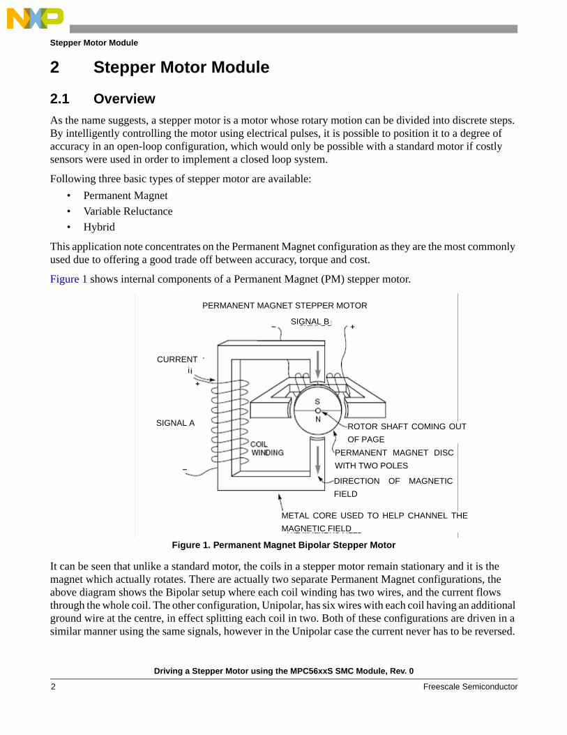
Figure 1 shows internal components of a Permanent Magnet (PM) stepper motor.
Figure 1. Permanent Magnet Bipolar Stepper Motor
It can be seen that unlike a standard motor, the coils in a stepper motor remain stationary and it is the magnet which actually rotates. There are actually two separate Permanent Magnet configurations, the above diagram shows the Bipolar setup where each coil winding has two wires, and the current flows through the whole coil. The other configuration, Unipolar, has six wires with each coil having an additional ground wire at the centre, in effect splitting each coil in two. Both of these configurations are driven in a similar manner using the same signals, however in the Unipolar case the current never has to be reversed.
PERMANENT MAGNET STEPPER MOTOR
SIGNAL B
CURRENTi
SIGNAL A ROTOR SHAFT COMING OUT
OF PAGE
PERMANENT MAGNET DISC
WITH TWO POLES
DIRECTION OF MAGNETIC
FIELD
METAL CORE USED TO HELP CHANNEL THE
MAGNETIC FIELD
Driving a Stepper Motor using the MPC56xxS SMC Module, Rev. 0
Freescale Semiconductor2
Stepper Motor Module
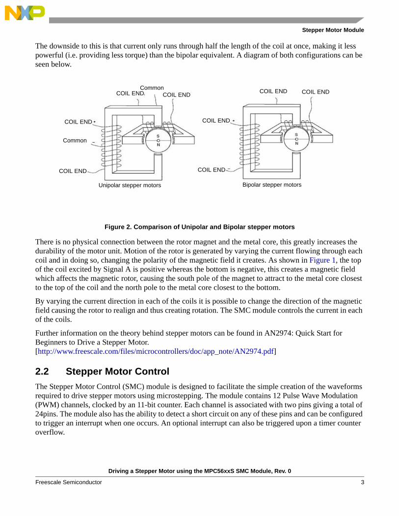
The downside to this is that current only runs through half the length of the coil at once, making it less powerful (i.e. providing less torque) than the bipolar equivalent. A diagram of both configurations can be seen below.
Figure 2. Comparison of Unipolar and Bipolar stepper motors
There is no physical connection between the rotor magnet and the metal core, this greatly increases the durability of the motor unit. Motion of the rotor is generated by varying the current flowing through each coil and in doing so, changing the polarity of the magnetic field it creates. As shown in Figure 1, the top of the coil excited by Signal A is positive whereas the bottom is negative, this creates a magnetic field which affects the magnetic rotor, causing the south pole of the magnet to attract to the metal core closest to the top of the coil and the north pole to the metal core closest to the bottom.
By varying the current direction in each of the coils it is possible to change the direction of the magnetic field causing the rotor to realign and thus creating rotation. The SMC module controls the current in each of the coils.
Further information on the theory behind stepper motors can be found in AN2974: Quick Start for Beginners to Drive a Stepper Motor. [http://www.freescale.com/files/microcontrollers/doc/app_note/AN2974.pdf]
2.2 Stepper Motor ControlThe Stepper Motor Control (SMC) module is designed to facilitate the simple creation of the waveforms required to drive stepper motors using microstepping. The module contains 12 Pulse Wave Modulation (PWM) channels, clocked by an 11-bit counter. Each channel is associated with two pins giving a total of 24pins. The module also has the ability to detect a short circuit on any of these pins and can be configured to trigger an interrupt when one occurs. An optional interrupt can also be triggered upon a timer counter overflow.
Unipolar stepper motors Bipolar stepper motors
CommonCOIL ENDCOIL END
COIL END
Common
COIL END
COIL END COIL END
COIL END
COIL END
Driving a Stepper Motor using the MPC56xxS SMC Module, Rev. 0
Freescale Semiconductor 3
Stepper Motor Module
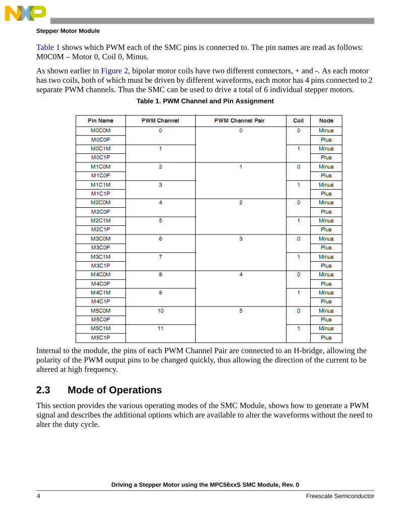
Table 1 shows which PWM each of the SMC pins is connected to. The pin names are read as follows: M0C0M – Motor 0, Coil 0, Minus.
As shown earlier in Figure 2, bipolar motor coils have two different connectors, + and -. As each motor has two coils, both of which must be driven by different waveforms, each motor has 4 pins connected to 2 separate PWM channels. Thus the SMC can be used to drive a total of 6 individual stepper motors.
Table 1. PWM Channel and Pin Assignment
Internal to the module, the pins of each PWM Channel Pair are connected to an H-bridge, allowing the polarity of the PWM output pins to be changed quickly, thus allowing the direction of the current to be altered at high frequency.
2.3 Mode of OperationsThis section provides the various operating modes of the SMC Module, shows how to generate a PWM signal and describes the additional options which are available to alter the waveforms without the need to alter the duty cycle.
Driving a Stepper Motor using the MPC56xxS SMC Module, Rev. 0
Freescale Semiconductor4
Stepper Motor Module
2.3.1 Operating Modes
Each individual PWM channel in the SCM can be configured to run in one of the following 3 modes which are selected in the MCCC[0-11] registers.
• Half H-bridge Mode – PWM signal is output on either the Minus or Plus pin. The other pin is released and can be used by another module or as GPIO. This mode facilitates the creation of a simple PWM signal which can be used for any purpose. There are two variations of this mode, one outputting the PWM on the M pin, the other on the P pin.
• Full H-bridge Mode – Both pins of the channel are used, one outputs the PWM signal, the other is set to drive either a logic high or low based on how it is configured.
• Dual Full H-bridge Mode – This mode is identical to Full H-bridge mode except that channels are paired together (0&1, 2&3 etc.) so that any changes to the duty cycle of the first channel will not have effect on the output until the duty cycle of the second channel has also been altered. As a stepper motor will require 2 PWM channels to operate, this allows a smooth transition when altering the waveforms.
NOTEAny writes to the second channel in Dual Full H-bridge Mode will happen immediately regardless of a prior write to the first channel has been carried out or not.
2.4 Creating Basic PWM SignalsPulse Width Modulation (PWM) is a method used by devices with digital outputs such as microcontrollers to create approximations of analog signals such as sine waves. By using this method the voltage and current which is supplied by output pins can be easily varied. This section shows how to use the SMC module to create PWM signals.
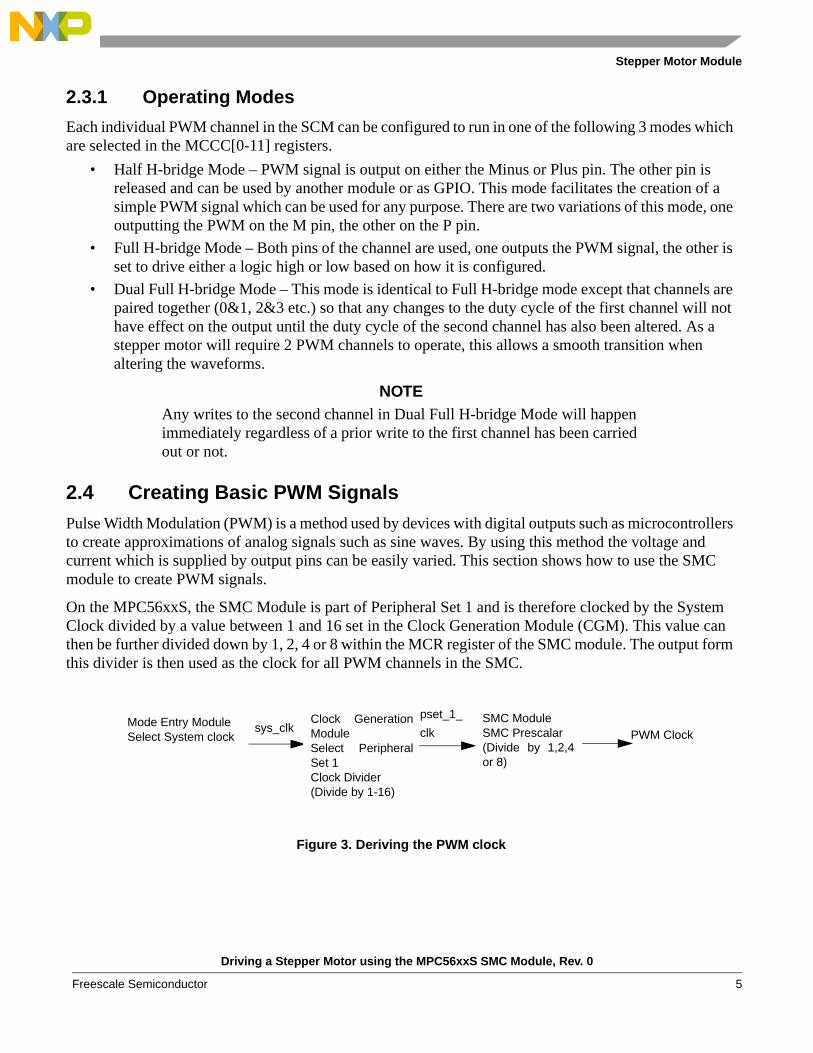
On the MPC56xxS, the SMC Module is part of Peripheral Set 1 and is therefore clocked by the System Clock divided by a value between 1 and 16 set in the Clock Generation Module (CGM). This value can then be further divided down by 1, 2, 4 or 8 within the MCR register of the SMC module. The output form this divider is then used as the clock for all PWM channels in the SMC.
Figure 3. Deriving the PWM clock
Mode Entry ModuleSelect System clock
Clock GenerationModuleSelect PeripheralSet 1Clock Divider(Divide by 1-16)
SMC ModuleSMC Prescalar(Divide by 1,2,4or 8)
PWM Clocksys_clk
pset_1_
clk
Driving a Stepper Motor using the MPC56xxS SMC Module, Rev. 0
Freescale Semiconductor 5
Stepper Motor Module
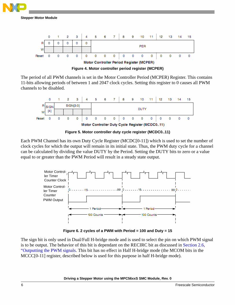
Figure 4. Motor controller period register (MCPER)
The period of all PWM channels is set in the Motor Controller Period (MCPER) Register. This contains 11-bits allowing periods of between 1 and 2047 clock cycles. Setting this register to 0 causes all PWM channels to be disabled.
Figure 5. Motor controller duty cycle register (MCDC0..11)
Each PWM Channel has its own Duty Cycle Register (MCDC[0-11]) which is used to set the number of clock cycles for which the output will remain in its initial state. Thus, the PWM duty cycle for a channel can be calculated by dividing the value DUTY by the Period. Setting the DUTY bits to zero or a value equal to or greater than the PWM Period will result in a steady state output.
Figure 6. 2 cycles of a PWM with Period = 100 and Duty = 15
The sign bit is only used in Dual/Full H-bridge mode and is used to select the pin on which PWM signal is to be output. The behavior of this bit is dependant on the RECIRC bit as discussed in Section 2.6, “Outputting the PWM signals. This bit has no effect in Half H-bridge mode (the MCOM bits in the MCCC[0-11] register, described below is used for this purpose in half H-bridge mode).
Motor Control-ler Timer Counter Clock
Motor Control-ler Timer Counter PWM Output
Driving a Stepper Motor using the MPC56xxS SMC Module, Rev. 0
Freescale Semiconductor6
Stepper Motor Module
The value in the Duty Cycle Register is double buffered to prevent the output being changed half-way though a PWM period. Thus the new value will only be become active once either:
• The channel is disabled.• In Full H-bridge mode: the count reaches the Period causing the timer to overflow, resetting it to 0.• In Dual Full H-bridge mode: the Duty Cycle Register of both channels of a PWM Channel Pair
have been written and the count has reached the Period causing the timer to overflow, resetting it to 0.
2.5 Advanced PWM functionsThe SMC contains a number of hardware implemented features to allow greater flexibility in the generation of PWM signals.
2.5.1 Alignment
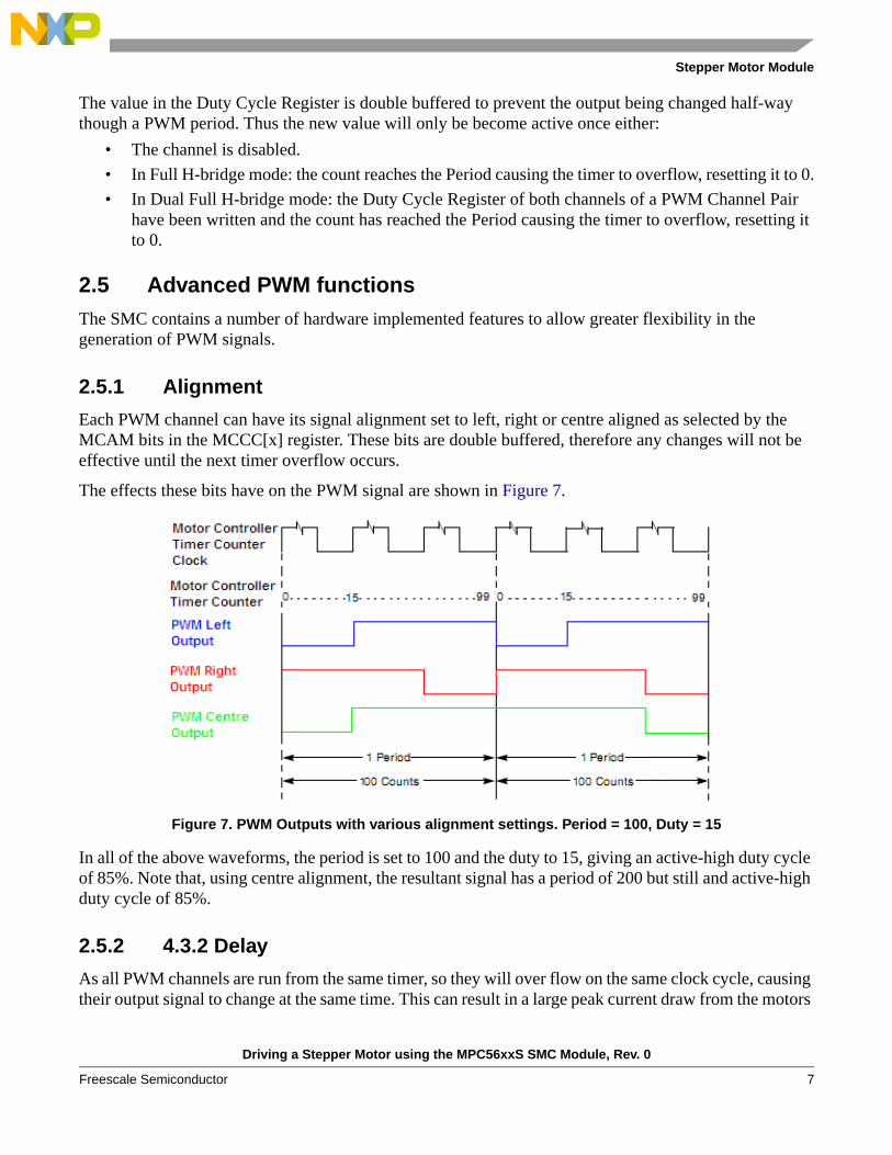
Each PWM channel can have its signal alignment set to left, right or centre aligned as selected by the MCAM bits in the MCCC[x] register. These bits are double buffered, therefore any changes will not be effective until the next timer overflow occurs.
The effects these bits have on the PWM signal are shown in Figure 7.
Figure 7. PWM Outputs with various alignment settings. Period = 100, Duty = 15
In all of the above waveforms, the period is set to 100 and the duty to 15, giving an active-high duty cycle of 85%. Note that, using centre alignment, the resultant signal has a period of 200 but still and active-high duty cycle of 85%.
2.5.2 4.3.2 Delay
As all PWM channels are run from the same timer, so they will over flow on the same clock cycle, causing their output signal to change at the same time. This can result in a large peak current draw from the motors
Driving a Stepper Motor using the MPC56xxS SMC Module, Rev. 0
Freescale Semiconductor 7
Stepper Motor Module
power supply or an excessive amount of transition-noise. To prevent this, each channel can be given a delay value which will stagger the PWM transitions by between 0 and 3 clock cycles. By making use of this the number of signals changing on a single clock can be quartered, greatly reducing the peak current draw and the transition noise.
The delay value is selected by the CD bits in the MCCC[0-11] registers.
2.5.3 4.3.3 Dither
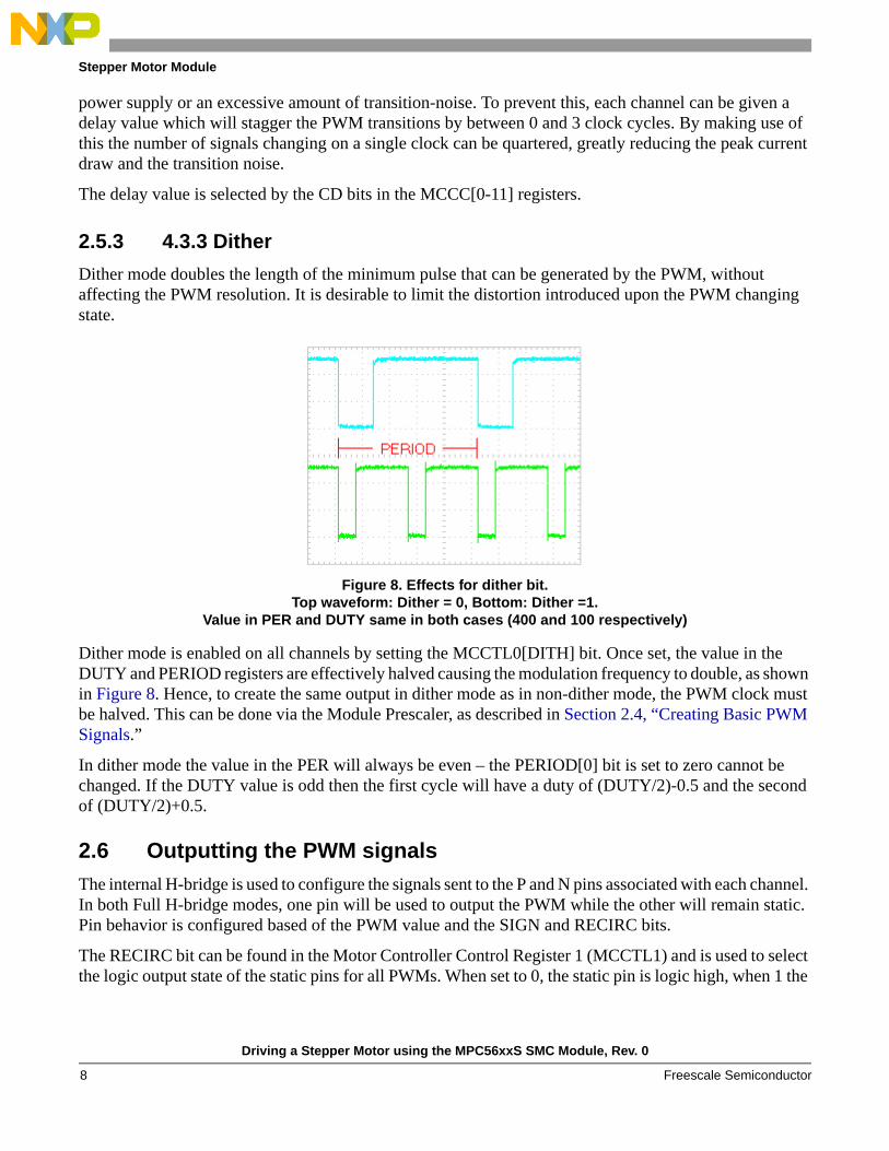
Dither mode doubles the length of the minimum pulse that can be generated by the PWM, without affecting the PWM resolution. It is desirable to limit the distortion introduced upon the PWM changing state.
Figure 8. Effects for dither bit.Top waveform: Dither = 0, Bottom: Dither =1.
Value in PER and DUTY same in both cases (400 and 100 respectively)
Dither mode is enabled on all channels by setting the MCCTL0[DITH] bit. Once set, the value in the DUTY and PERIOD registers are effectively halved causing the modulation frequency to double, as shown in Figure 8. Hence, to create the same output in dither mode as in non-dither mode, the PWM clock must be halved. This can be done via the Module Prescaler, as described in Section 2.4, “Creating Basic PWM Signals.”
In dither mode the value in the PER will always be even – the PERIOD[0] bit is set to zero cannot be changed. If the DUTY value is odd then the first cycle will have a duty of (DUTY/2)-0.5 and the second of (DUTY/2)+0.5.
2.6 Outputting the PWM signalsThe internal H-bridge is used to configure the signals sent to the P and N pins associated with each channel. In both Full H-bridge modes, one pin will be used to output the PWM while the other will remain static. Pin behavior is configured based of the PWM value and the SIGN and RECIRC bits.
The RECIRC bit can be found in the Motor Controller Control Register 1 (MCCTL1) and is used to select the logic output state of the static pins for all PWMs. When set to 0, the static pin is logic high, when 1 the
Driving a Stepper Motor using the MPC56xxS SMC Module, Rev. 0
Freescale Semiconductor8
Stepper Motor Module
static pin is logic low. This bit should only be altered when no channels are running in Dual/Full H-bridge mode. The bit has no effect in Half H-Bridge mode as the static channel is disabled in this case.
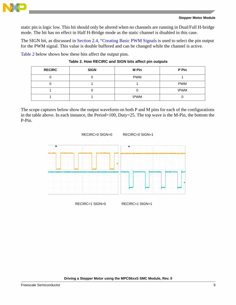
The SIGN bit, as discussed in Section 2.4, “Creating Basic PWM Signals is used to select the pin output for the PWM signal. This value is double buffered and can be changed while the channel is active.
Table 2 below shows how these bits affect the output pins.
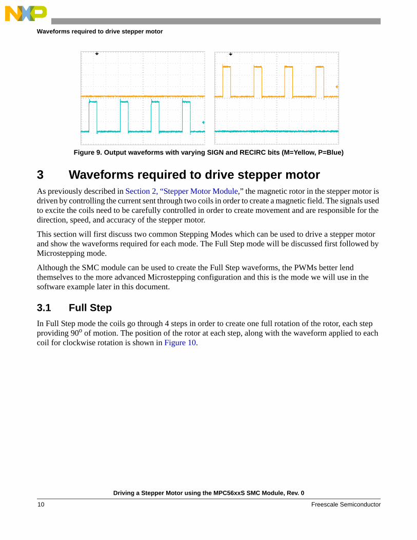
The scope captures below show the output waveform on both P and M pins for each of the configurations in the table above. In each instance, the Period=100, Duty=25. The top wave is the M-Pin, the bottom the P-Pin.
Table 2. How RECIRC and SIGN bits affect pin outputs
RECIRC SIGN M Pin P Pin
0 0 PWM 1
0 1 1 PWM
1 0 0 \PWM
1 1 \PWM 0
RECIRC=0 SIGN=0 RECIRC=0 SIGN=1
RECIRC=1 SIGN=0 RECIRC=1 SIGN=1
Driving a Stepper Motor using the MPC56xxS SMC Module, Rev. 0
Freescale Semiconductor 9
Waveforms required to drive stepper motor
Figure 9. Output waveforms with varying SIGN and RECIRC bits (M=Yellow, P=Blue)
3 Waveforms required to drive stepper motorAs previously described in Section 2, “Stepper Motor Module,” the magnetic rotor in the stepper motor is driven by controlling the current sent through two coils in order to create a magnetic field. The signals used to excite the coils need to be carefully controlled in order to create movement and are responsible for the direction, speed, and accuracy of the stepper motor.
This section will first discuss two common Stepping Modes which can be used to drive a stepper motor and show the waveforms required for each mode. The Full Step mode will be discussed first followed by Microstepping mode.
Although the SMC module can be used to create the Full Step waveforms, the PWMs better lend themselves to the more advanced Microstepping configuration and this is the mode we will use in the software example later in this document.
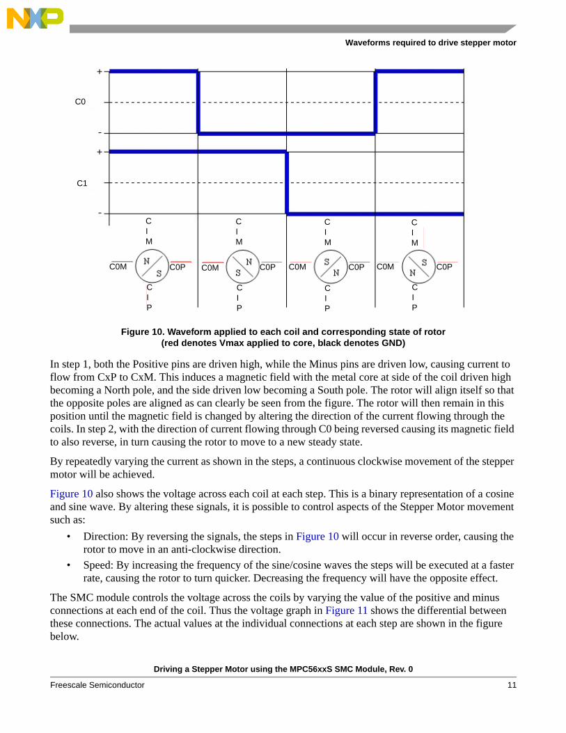
3.1 Full StepIn Full Step mode the coils go through 4 steps in order to create one full rotation of the rotor, each step providing 90o of motion. The position of the rotor at each step, along with the waveform applied to each coil for clockwise rotation is shown in Figure 10.
Driving a Stepper Motor using the MPC56xxS SMC Module, Rev. 0
Freescale Semiconductor10
Waveforms required to drive stepper motor
Figure 10. Waveform applied to each coil and corresponding state of rotor(red denotes Vmax applied to core, black denotes GND)
In step 1, both the Positive pins are driven high, while the Minus pins are driven low, causing current to flow from CxP to CxM. This induces a magnetic field with the metal core at side of the coil driven high becoming a North pole, and the side driven low becoming a South pole. The rotor will align itself so that the opposite poles are aligned as can clearly be seen from the figure. The rotor will then remain in this position until the magnetic field is changed by altering the direction of the current flowing through the coils. In step 2, with the direction of current flowing through C0 being reversed causing its magnetic field to also reverse, in turn causing the rotor to move to a new steady state.
By repeatedly varying the current as shown in the steps, a continuous clockwise movement of the stepper motor will be achieved.
Figure 10 also shows the voltage across each coil at each step. This is a binary representation of a cosine and sine wave. By altering these signals, it is possible to control aspects of the Stepper Motor movement such as:
• Direction: By reversing the signals, the steps in Figure 10 will occur in reverse order, causing the rotor to move in an anti-clockwise direction.
• Speed: By increasing the frequency of the sine/cosine waves the steps will be executed at a faster rate, causing the rotor to turn quicker. Decreasing the frequency will have the opposite effect.
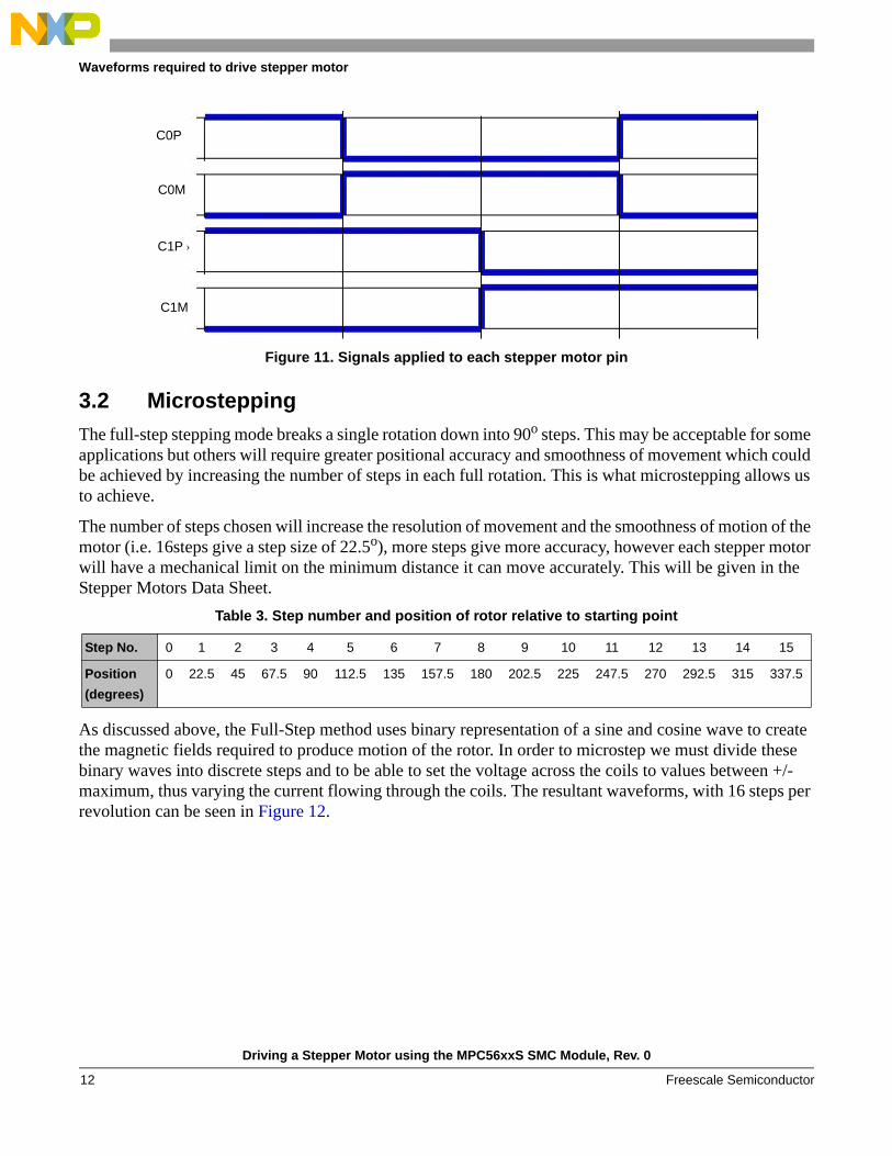
The SMC module controls the voltage across the coils by varying the value of the positive and minus connections at each end of the coil. Thus the voltage graph in Figure 11 shows the differential between these connections. The actual values at the individual connections at each step are shown in the figure below.
C0
C1
C0M C0P
CIP
CIM
C0M
CIM
CIP
C0P
CIM
C0M C0P
CIP
CIM
C0M C0P
CIP
Driving a Stepper Motor using the MPC56xxS SMC Module, Rev. 0
Freescale Semiconductor 11
Waveforms required to drive stepper motor
Figure 11. Signals applied to each stepper motor pin
3.2 MicrosteppingThe full-step stepping mode breaks a single rotation down into 90o steps. This may be acceptable for some applications but others will require greater positional accuracy and smoothness of movement which could be achieved by increasing the number of steps in each full rotation. This is what microstepping allows us to achieve.
The number of steps chosen will increase the resolution of movement and the smoothness of motion of the motor (i.e. 16steps give a step size of 22.5o), more steps give more accuracy, however each stepper motor will have a mechanical limit on the minimum distance it can move accurately. This will be given in the Stepper Motors Data Sheet.
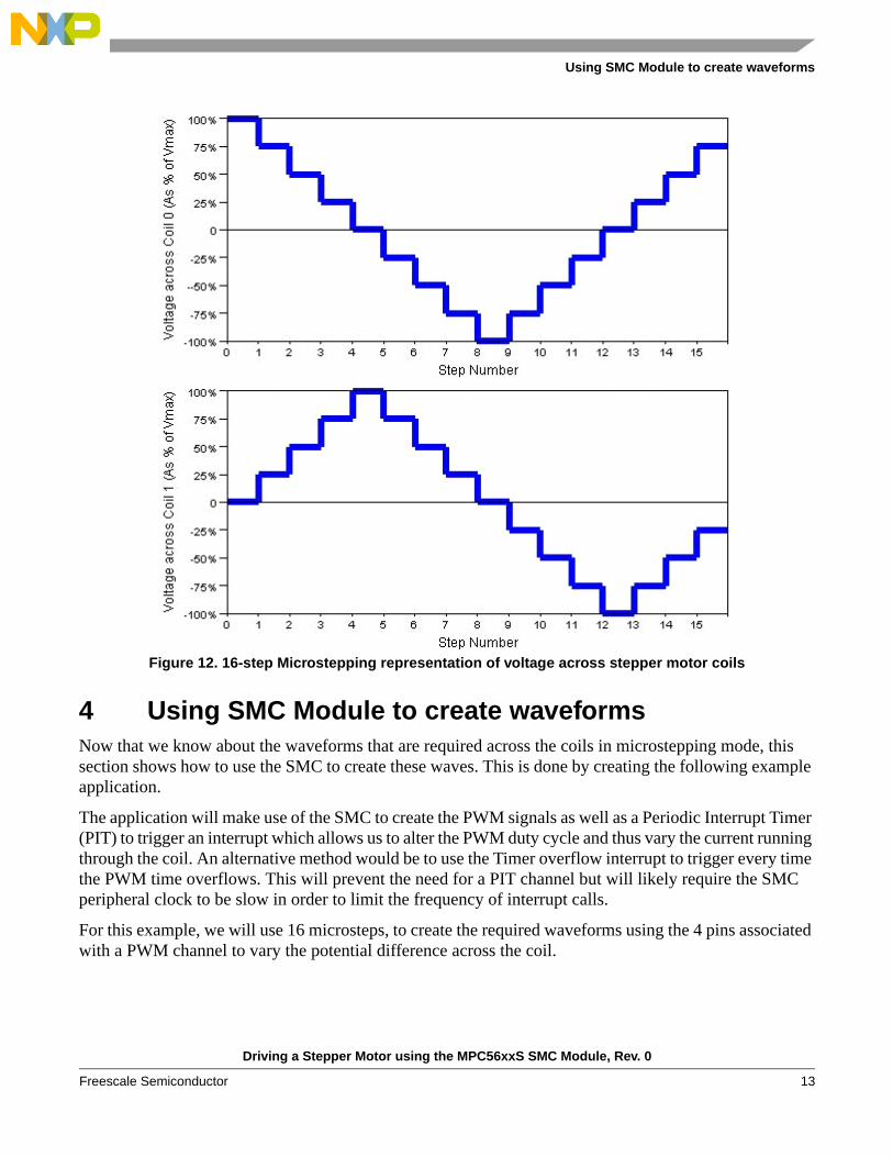
As discussed above, the Full-Step method uses binary representation of a sine and cosine wave to create the magnetic fields required to produce motion of the rotor. In order to microstep we must divide these binary waves into discrete steps and to be able to set the voltage across the coils to values between +/- maximum, thus varying the current flowing through the coils. The resultant waveforms, with 16 steps per revolution can be seen in Figure 12.
Table 3. Step number and position of rotor relative to starting point
Step No. 0 1 2 3 4 5 6 7 8 9 10 11 12 13 14 15
Position (degrees)
0 22.5 45 67.5 90 112.5 135 157.5 180 202.5 225 247.5 270 292.5 315 337.5
C0P
C0M
C1P
C1M
Driving a Stepper Motor using the MPC56xxS SMC Module, Rev. 0
Freescale Semiconductor12
Using SMC Module to create waveforms
Figure 12. 16-step Microstepping representation of voltage across stepper motor coils
4 Using SMC Module to create waveformsNow that we know about the waveforms that are required across the coils in microstepping mode, this section shows how to use the SMC to create these waves. This is done by creating the following example application.
The application will make use of the SMC to create the PWM signals as well as a Periodic Interrupt Timer (PIT) to trigger an interrupt which allows us to alter the PWM duty cycle and thus vary the current running through the coil. An alternative method would be to use the Timer overflow interrupt to trigger every time the PWM time overflows. This will prevent the need for a PIT channel but will likely require the SMC peripheral clock to be slow in order to limit the frequency of interrupt calls.
For this example, we will use 16 microsteps, to create the required waveforms using the 4 pins associated with a PWM channel to vary the potential difference across the coil.
Driving a Stepper Motor using the MPC56xxS SMC Module, Rev. 0
Freescale Semiconductor 13
Using SMC Module to create waveforms
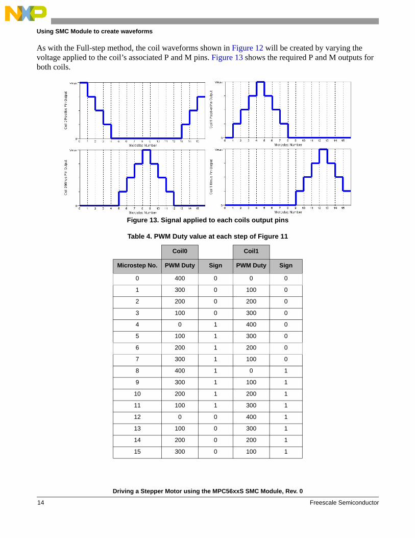
As with the Full-step method, the coil waveforms shown in Figure 12 will be created by varying the voltage applied to the coil’s associated P and M pins. Figure 13 shows the required P and M outputs for both coils.
Figure 13. Signal applied to each coils output pins
Table 4. PWM Duty value at each step of Figure 11
Coil0 Coil1
Microstep No. PWM Duty Sign PWM Duty Sign
0 400 0 0 0
1 300 0 100 0
2 200 0 200 0
3 100 0 300 0
4 0 1 400 0
5 100 1 300 0
6 200 1 200 0
7 300 1 100 0
8 400 1 0 1
9 300 1 100 1
10 200 1 200 1
11 100 1 300 1
12 0 0 400 1
13 100 0 300 1
14 200 0 200 1
15 300 0 100 1
Driving a Stepper Motor using the MPC56xxS SMC Module, Rev. 0
Freescale Semiconductor14
Using SMC Module to create waveforms
The steps in the Table 4 are created using the PWM. For this example, the period of both PWMs will be set to 0x400. This will allow easy calculation of the PWM settings required for the other microsteps. If a negative step waveform be required, these steps should be reversed.
Notice that for each coil, the PWM is only output to either P or M at once while the other pin remains static. As previously discussed, the value of the static pin is controlled by the RECIRC bit. In this instance the static is set to zero, thus RECIRC = 1.
The PWM duty value defines the duration for which the output remains in its initial state. Since RECIRC = 1, the initial state of the output is HIGH (see Table 2).
Apart from varying the period, it will also be necessary to change which pin to output the PWM and which to remain static, by altering the SIGN bit. The waveforms we have chosen for this example (Figure 13) requires the static pin to remain low thus the static current should be recirculated on the low side transistors. In this, RECIRC bit should be set to 0 during initialization.
Every fourth microstep corresponds with a changing full-step. At these points the SIGN bit may require changing. From Figure 13 it can be seen that selection of which output pin is static and which has the PWM dependant on which direction the motor is to be driven in. For example, at microstep 4 on Coil 0 - if the motor is to be driven clockwise then the PWM should be output on the M pin (SIGN = 1) however if the intention is to drive the motor anti-clockwise then the PWM should be driven onto the P-pin (SIGN=0).
As previously stated, a periodic interrupt, triggered by the PIT will be used to alter the duty and sign values as appropriate at each microstep.
4.1 Program StructureThe program will be divided into 2 main sections. The first of these will be the initialization covering the setting up of the relevant modules, the second will be the PIT interrupt which will update the duty and SIGN values at each microstep.
4.2 Initialization1. Configure the pins used to drive the stepper motor using the Pad Configuration Registers (PCR) in
the SIU module. This example will make use of 2 PWM channels to drive a single stepper motor, giving a requirement of 4 pins. The PCR for these pins should be set to the correct function and the output buffer should be enabled.
2. The SMC module configuration should then be carried out• The required clock divider value should be configured to set the required module clock.• The RECIRC bit should set as appropriate. In this case it is left in its reset state of 0.• The period should then be set as appropriate.3. The individual PWM channels should then be configured. This example will use channels 0 and 1.
These should be configured to Dual Full H-bridge mode and set as left aligned.4. A global variable named direction will be used to select whether the rotor should turn in a
clock-wise or anti-clockwise direction.
Driving a Stepper Motor using the MPC56xxS SMC Module, Rev. 0
Freescale Semiconductor 15
Using SMC Module to create waveforms
5. Configure and enable PIT interrupt. The PIT interrupt will control how often the rotor will microstep, thus it controls the speed of the rotor. The longer the PIT period, the slower the rotor will rotate.
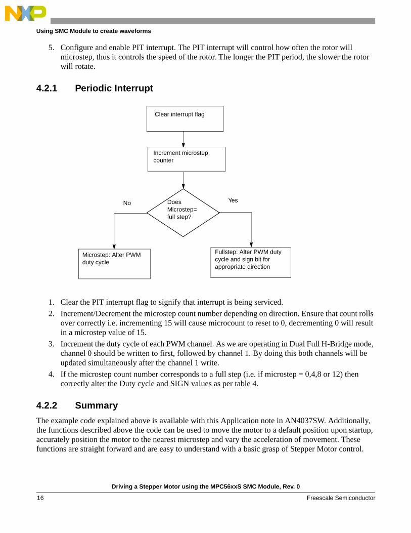
4.2.1 Periodic Interrupt
1. Clear the PIT interrupt flag to signify that interrupt is being serviced.2. Increment/Decrement the microstep count number depending on direction. Ensure that count rolls
over correctly i.e. incrementing 15 will cause microcount to reset to 0, decrementing 0 will result in a microstep value of 15.
3. Increment the duty cycle of each PWM channel. As we are operating in Dual Full H-Bridge mode, channel 0 should be written to first, followed by channel 1. By doing this both channels will be updated simultaneously after the channel 1 write.
4. If the microstep count number corresponds to a full step (i.e. if microstep = 0,4,8 or 12) then correctly alter the Duty cycle and SIGN values as per table 4.
4.2.2 Summary
The example code explained above is available with this Application note in AN4037SW. Additionally, the functions described above the code can be used to move the motor to a default position upon startup, accurately position the motor to the nearest microstep and vary the acceleration of movement. These functions are straight forward and are easy to understand with a basic grasp of Stepper Motor control.
Microstep: Alter PWM duty cycle
Does Microstep=full step?
YesNo
Fullstep: Alter PWM duty cycle and sign bit for appropriate direction
Increment microstep counter
Clear interrupt flag
Driving a Stepper Motor using the MPC56xxS SMC Module, Rev. 0
Freescale Semiconductor16
Advanced Features
5 Advanced Features
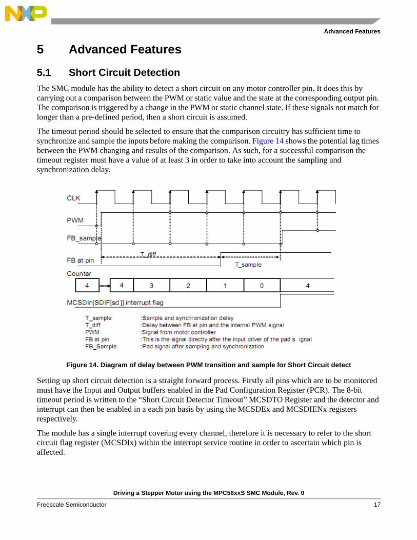
5.1 Short Circuit DetectionThe SMC module has the ability to detect a short circuit on any motor controller pin. It does this by carrying out a comparison between the PWM or static value and the state at the corresponding output pin. The comparison is triggered by a change in the PWM or static channel state. If these signals not match for longer than a pre-defined period, then a short circuit is assumed.
The timeout period should be selected to ensure that the comparison circuitry has sufficient time to synchronize and sample the inputs before making the comparison. Figure 14 shows the potential lag times between the PWM changing and results of the comparison. As such, for a successful comparison the timeout register must have a value of at least 3 in order to take into account the sampling and synchronization delay.
Figure 14. Diagram of delay between PWM transition and sample for Short Circuit detect
Setting up short circuit detection is a straight forward process. Firstly all pins which are to be monitored must have the Input and Output buffers enabled in the Pad Configuration Register (PCR). The 8-bit timeout period is written to the “Short Circuit Detector Timeout” MCSDTO Register and the detector and interrupt can then be enabled in a each pin basis by using the MCSDEx and MCSDIENx registers respectively.
The module has a single interrupt covering every channel, therefore it is necessary to refer to the short circuit flag register (MCSDIx) within the interrupt service routine in order to ascertain which pin is affected.
Driving a Stepper Motor using the MPC56xxS SMC Module, Rev. 0
Freescale Semiconductor 17
Advanced Features
5.2 Stall DetectionThe MPC56xxS device contains a separate Stepper Stall Detect (SSD) module which uses the same pins as the SMC and can be used to detect if a driven stepper motor has ceased to move, for example, when it has reached either of its extremities. This is very useful upon start up, reset or in case of error, as it can ensure that the motor returns to its starting position.
The SSD can be given control of the Stepper Motor in these instances and return the stepper motor to its starting position before giving control back to the SMC.
The SSD is limited to using Full-step movement and therefore cannot obtain the same accuracy and smoothness of movement as the SMC. As such it is recommended that it only be used for Stall Detection purposes.
More details of the SSD can be found in AN3330: Introduction to the Stepper Stall Detector Module. [http://www.freescale.com/files/microcontrollers/doc/app_note/AN3330.pdf]
Driving a Stepper Motor using the MPC56xxS SMC Module, Rev. 0
Freescale Semiconductor18

THIS PAGE IS INTENTIONALLY BLANK
Driving a Stepper Motor using the MPC56xxS SMC Module, Rev. 0
Freescale Semiconductor 19
Document Number: AN4037Rev. 002/2010
How to Reach Us:
Home Page:www.freescale.com
Web Support:http://www.freescale.com/support
USA/Europe or Locations Not Listed:Freescale Semiconductor, Inc.Technical Information Center, EL5162100 East Elliot RoadTempe, Arizona 85284+1-800-521-6274 or +1-480-768-2130www.freescale.com/support
Europe, Middle East, and Africa:Freescale Halbleiter Deutschland GmbHTechnical Information CenterSchatzbogen 781829 Muenchen, Germany+44 1296 380 456 (English)+46 8 52200080 (English)+49 89 92103 559 (German)+33 1 69 35 48 48 (French)www.freescale.com/support
Japan:Freescale Semiconductor Japan Ltd.HeadquartersARCO Tower 15F1-8-1, Shimo-Meguro, Meguro-ku,Tokyo 153-0064Japan0120 191014 or +81 3 5437 [email protected]
Asia/Pacific:Freescale Semiconductor China Ltd.Exchange Building 23FNo. 118 Jianguo RoadChaoyang DistrictBeijing 100022 China +86 10 5879 [email protected]
For Literature Requests Only:Freescale Semiconductor Literature Distribution Center1-800-441-2447 or 303-675-2140Fax: [email protected]
Information in this document is provided solely to enable system and software implementers to use Freescale Semiconductor products. There are no express or implied copyright licenses granted hereunder to design or fabricate any integrated circuits or integrated circuits based on the information in this document.
Freescale Semiconductor reserves the right to make changes without further notice to any products herein. Freescale Semiconductor makes no warranty, representation or guarantee regarding the suitability of its products for any particular purpose, nor does Freescale Semiconductor assume any liability arising out of the application or use of any product or circuit, and specifically disclaims any and all liability, including without limitation consequential or incidental damages. “Typical” parameters that may be provided in Freescale Semiconductor data sheets and/or specifications can and do vary in different applications and actual performance may vary over time. All operating parameters, including “Typicals”, must be validated for each customer application by customer’s technical experts. Freescale Semiconductor does not convey any license under its patent rights nor the rights of others. Freescale Semiconductor products are not designed, intended, or authorized for use as components in systems intended for surgical implant into the body, or other applications intended to support or sustain life, or for any other application in which the failure of the Freescale Semiconductor product could create a situation where personal injury or death may occur. Should Buyer purchase or use Freescale Semiconductor products for any such unintended or unauthorized application, Buyer shall indemnify and hold Freescale Semiconductor and its officers, employees, subsidiaries, affiliates, and distributors harmless against all claims, costs, damages, and expenses, and reasonable attorney fees arising out of, directly or indirectly, any claim of personal injury or death associated with such unintended or unauthorized use, even if such claim alleges that Freescale Semiconductor was negligent regarding the design or manufacture of the part.
RoHS-compliant and/or Pb-free versions of Freescale products have the functionality and electrical characteristics as their non-RoHS-compliant and/or non-Pb-free counterparts. For further information, see http://www.freescale.com or contact your Freescale sales representative.
For information on Freescale’s Environmental Products program, go to http://www.freescale.com/epp.
Freescale™ and the Freescale logo are trademarks of Freescale Semiconductor, Inc. All other product or service names are the property of their respective owners.© Freescale Semiconductor, Inc. 2010. All rights reserved.