Embed Size (px)
Citation preview
1
Drives
A Carraro GroupCom
pany

2
3
Carraro is a multinational Group and world leader in power transmission systems. Its core business consists in conceiving, designing, validating, manufacturing and marketing drive systems for construction equipment, agricultural tractors, material handling, light commercial vehicles, automobiles, renewable energies and stationary applications (such as escalators and wind generators).
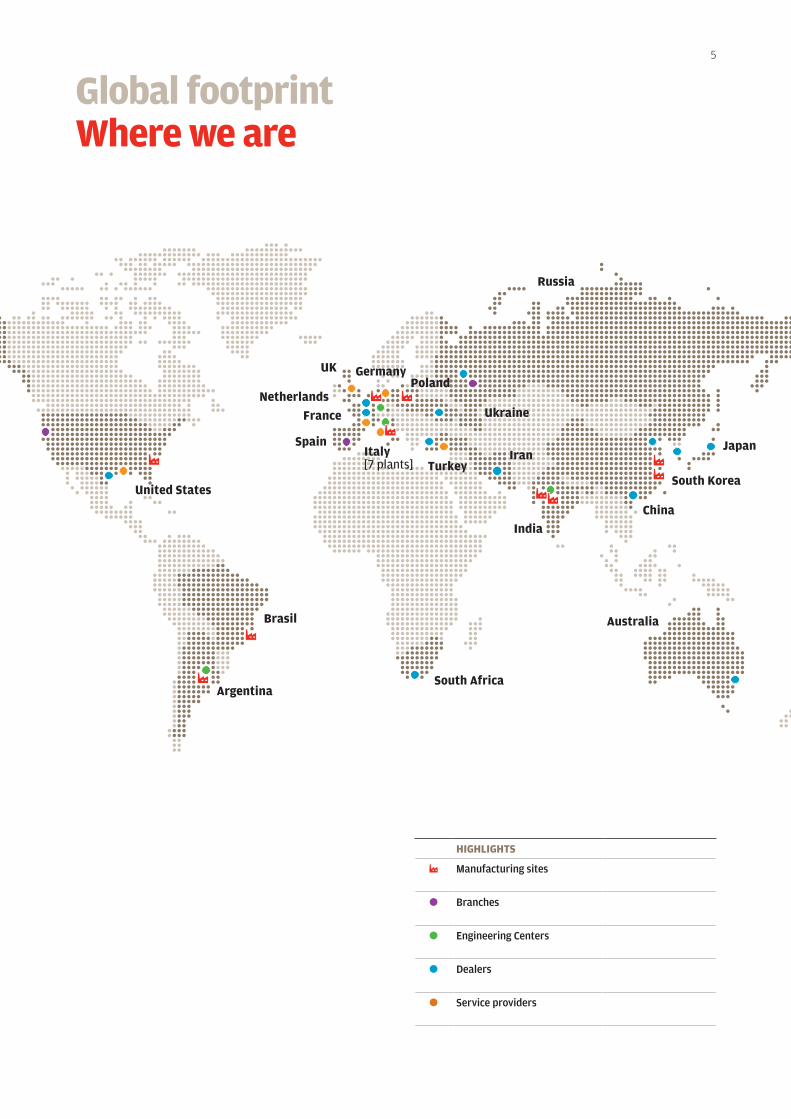
The Group, whose holding company Carraro Spa has been listed on the Italian Stock Exchange since 1995, is based in Campodarsego (Padua) and has manufacturing facilities in Italy, Germany, Poland, Argentina, the United States, India and China.
IntroductionCarraro Group
4
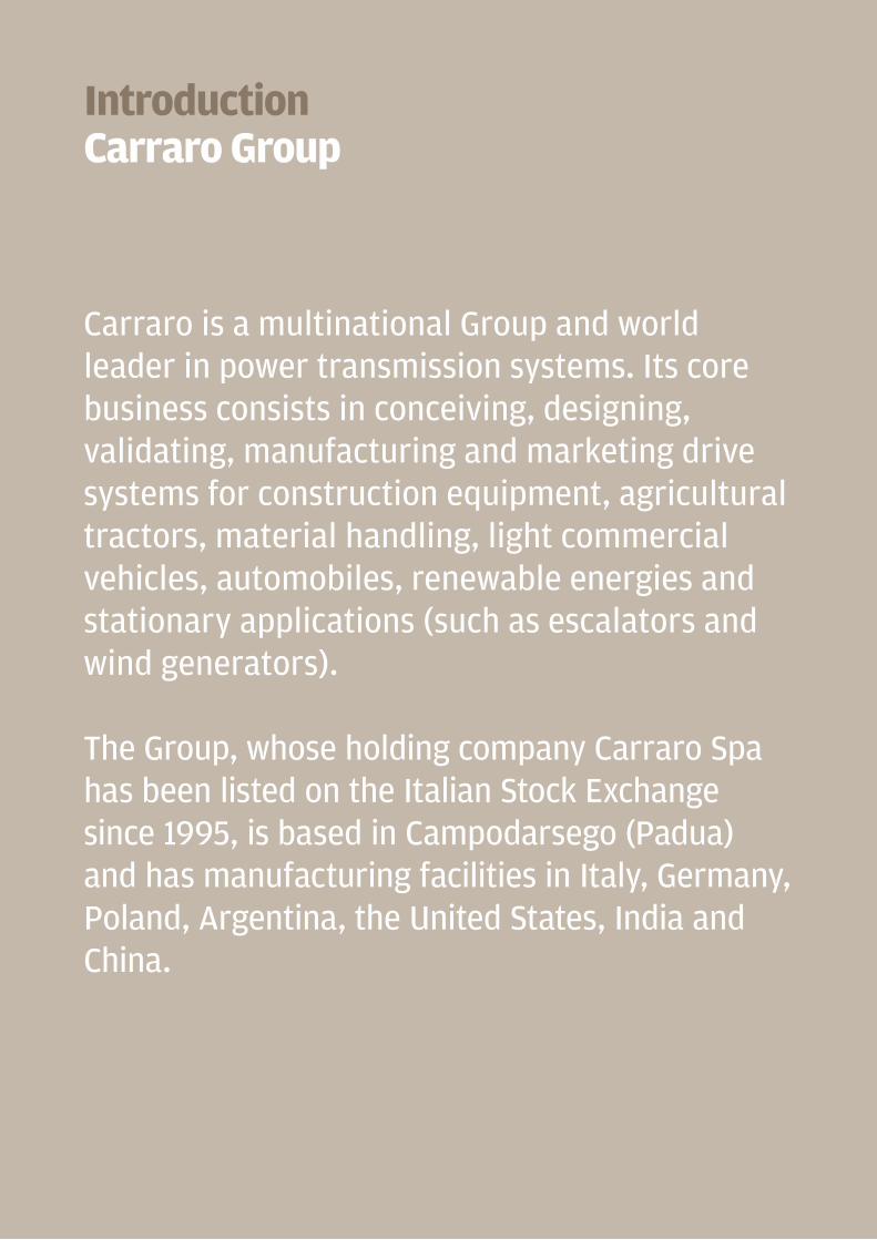
Inverters and power control, frequency converters, applied electronicsfor industrial plants, automation,renewable energies management(photovoltaic & wind energy), hybrid and electric vehicle powertrains.
Integrated solutions (axles, transmis-sions, final & swing drives) for a wide range of applications: mining, construc-tion equipment, agricultural tractors, light commercial vehicles, material handling and stationary applications (such as escalators & wind energy gen-erators).
Low & high diameter steel gears, sinter-ized components and gears for earth-moving machines, agricultural trac-tors, cars, light commercial vehicles, two-wheel vehicles, powertools, garden equipment, railway and industrial ap-plications, in particular for wind and solar energy.
Design and manufacturing of standard, vineyard & orchard tractors, from 50 to 100 HP; offering a wide range of engi-neering services, from simple consul-tancy to “turnkey” projects.
The GroupBusiness Areas
5
Spain
China
South Korea
Australia
Japan
Argentina
Brasil
South Africa
United States
Italy[7 plants]
GermanyUK
Netherlands
France
IranTurkey
Poland
Russia
India
Ukraine
Global footprintWhere we are
HIGHlIGHTs
Manufacturing sites
Branches
Engineering Centers
Dealers
Service providers
6
Carraro Drive Tech is the Business Unit managing the Carraro Group core busi-ness: designing, manufacturingand marketing drivelines, axles and transmissions, travel & cutter drives and electronic control units.
Wherever there is a need for integratedtransmission systems for off- and on-highway vehicles, Carraro Drive Techhas the solution, with a complete, di-versified product range for agriculture,construction equipment, mining, andmaterial handling.
Carraro drivelines have been optimisedfor the individual markets of applica-tion, to guarantee the very best effi-ciency and most practical vehiclelayout.
All this is possible thanks to the widerange of combinations of rigid andsteering axles and mechanical, auto-matic or semi-automatic transmissions. The Carraro systems have been de-signed for the optimal integrationof mechanics and hydraulics, under the supervision of an advanced electronic control unit. This can best manage the whole driveline while monitoring and diagnosing the vehicle functions.
Carraro Drive TechDrivelines & Drives

7
Front & Rear Axles, modular or monolithic structure, steering or rigid, with or without integrated indipendent suspension
Electronic Control Units for Transmissions & Powertrains Management
Synchro Shuttle, Power Synchro & Power Shift transmissions for Construction Equipment, transaxles for Agricultural tractors, also with VaryT version
Our solutions
Travel & CutterDrives

12
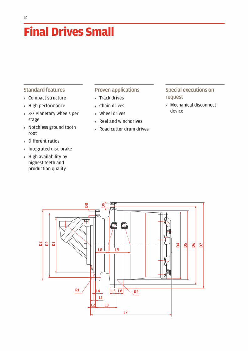
Standard features› Compact structure
› High performance
› 3-7 Planetary wheels per stage
› Notchless ground tooth root
› Different ratios
› Integrated disc-brake
› High availability by highest teeth and production quality
Proven applications› Track drives
› Chain drives
› Wheel drives
› Reel and winchdrives
› Road cutter drum drives
Special executions on request› Mechanical disconnect
device
Final Drives small D
3
D2
D1
L6L5L4
L9L8
L7
L3L2
L1R2R1
D6
D5
D4
D9
D8
D7
13
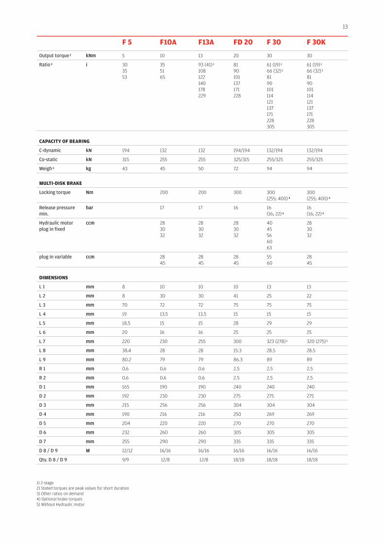
F 5 F10A F13A FD 20 F 30 F 30K
Output torque 2 kNm 5 10 13 20 30 30
Ratio 3 i 303553
355165
93 (41) 1
108122140178229
8190101137171228
61 (19) 1
66 (32) 1
8190101114121137171228305
61 (19) 1
66 (32) 1
8190101114121137171228305
CApACITy OF BEArInG
C-dynamic kN 194 132 132 194/194 132/194 132/194
Co-static kN 315 255 255 325/315 255/325 255/325
Weigh 5 kg 43 45 50 72 94 94
MulTI-DIsK BrAKE
Locking torque Nm 200 200 300 300 (255; 400) 4
300 (255; 400) 4
Release pressure min.
bar 17 17 16 16 (16; 22) 4
16 (16; 22) 4
Hydraulic motor plug in fixed
ccm 283032
283032
283032
4045566063
283032
plug in variable ccm 2845
2845
2845
55 60
2845
DIMEnsIOns
L 1 mm 8 10 10 10 13 13
L 2 mm 8 30 30 41 25 22
L 3 mm 70 72 72 75 75 75
L 4 mm 19 13.5 13.5 15 15 15
L 5 mm 18.5 15 15 28 29 29
L 6 mm 20 16 16 25 25 25
L 7 mm 220 230 255 300 323 (278) 1 320 (275) 1
L 8 mm 38.4 28 28 15.3 28.5 28.5
L 9 mm 80.2 79 79 86.3 89 89
R 1 mm 0.6 0.6 0.6 2.5 2.5 2.5
R 2 mm 0.6 0.6 0.6 2.5 2.5 2.5
D 1 mm 165 190 190 240 240 240
D 2 mm 192 230 230 275 275 275
D 3 mm 215 256 256 304 304 304
D 4 mm 190 216 216 250 269 269
D 5 mm 204 220 220 270 270 270
D 6 mm 232 260 260 305 305 305
D 7 mm 255 290 290 335 335 335
D 8 / D 9 M 12/12 16/16 16/16 16/16 16/16 16/16
Qty. D 8 / D 9 9/9 12/8 12/8 18/18 18/18 18/18
1) 2-stage 2) Stated torques are peak values for short duration3) Other ratios on demand 4) Optional brake torques 5) Without Hydraulic motor

14
Standard features› Compact structure
› High performance
› 3-7 Planetary wheels per stage
› Notchless ground tooth root
› Different ratios
› Integrated disc-brake
› High availability by highest teeth and production quality
Proven applications› Track drives
› Chain drives
› Wheel drives
› Reel and winchdrives
› Road cutter drum drives
Special executions on request› Mechanical disconnect
device
Final Drives Medium D
3
D2
D1
L6L5L4
L9L8
L7
L3L2
L1R2R1
D6
D5
D4
D9
D8
D7
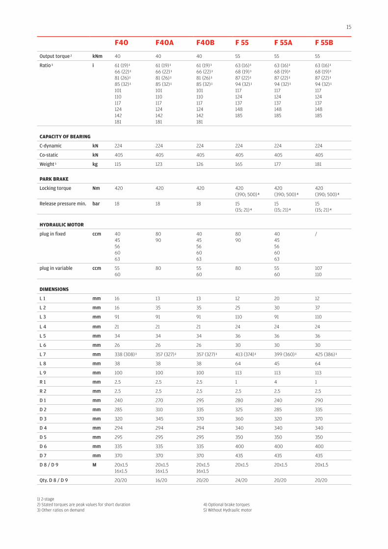
15
F40 F40A F40B F 55 F 55A F 55B
Output torque 2 kNm 40 40 40 55 55 55
Ratio 3 i 61 (19) 1
66 (22) 1
81 (26) 1
85 (32) 1
101 110 117 124 142 181
61 (19) 1
66 (22) 1
81 (26) 1
85 (32) 1
101 110 117 124 142 181
61 (19) 1
66 (22) 1
81 (26) 1
85 (32) 1
101 110 117 124 142 181
63 (16) 1 68 (19) 1 87 (22) 1 94 (32) 1 117124 137 148 185
63 (16) 1 68 (19) 1 87 (22) 1 94 (32) 1 117124 137 148 185
63 (16) 1 68 (19) 1 87 (22) 1 94 (32) 1 117124 137 148 185
CApACITy OF BEArInG
C-dynamic kN 224 224 224 224 224 224
Co-static kN 405 405 405 405 405 405
Weight 5 kg 115 123 126 165 177 181
pArK BrAKE
Locking torque Nm 420 420 420 420 (390; 500) 4
420 (390; 500) 4
420 (390; 500) 4
Release pressure min. bar 18 18 18 15 (15; 21) 4
15 (15; 21) 4
15 (15; 21) 4
HyDrAulIC MOTOr
plug in fixed ccm 4045566063
8090
4045566063
8090
4045566063
/
plug in variable ccm 5560
80 5560
80 5560
107110
DIMEnsIOns
L 1 mm 16 13 13 12 20 12
L 2 mm 16 35 35 25 30 37
L 3 mm 91 91 91 110 91 110
L 4 mm 21 21 21 24 24 24
L 5 mm 34 34 34 36 36 36
L 6 mm 26 26 26 30 30 30
L 7 mm 338 (308) 1 357 (327) 1 357 (327) 1 413 (374) 1 399 (360) 1 425 (386) 1
L 8 mm 38 38 38 64 45 64
L 9 mm 100 100 100 113 113 113
R 1 mm 2.5 2.5 2.5 1 4 1
R 2 mm 2.5 2.5 2.5 2.5 2.5 2.5
D 1 mm 240 270 295 280 240 290
D 2 mm 285 310 335 325 285 335
D 3 mm 320 345 370 360 320 370
D 4 mm 294 294 294 340 340 340
D 5 mm 295 295 295 350 350 350
D 6 mm 335 335 335 400 400 400
D 7 mm 370 370 370 435 435 435
D 8 / D 9 M 20x1.516x1.5
20x1.516x1.5
20x1.516x1.5
20x1.5 20x1.5 20x1.5
Qty. D 8 / D 9 20/20 16/20 20/20 24/20 20/20 20/20
1) 2-stage 2) Stated torques are peak values for short duration3) Other ratios on demand
4) Optional brake torques 5) Without Hydraulic motor

16
D3
D2
D1
L6L5L4
L9L8
L7
L3L2
L1R2R1
D6
D5
D4
D9
D8
D7
Standard features› Compact structure
› High performance
› 3-7 Planetary wheels per stage
› Notchless ground tooth root
› Different ratios
› Integrated disc-brake
› High availability by highest teeth and production quality
Proven applications› Track drives
› Chain drives
› Wheel drives
› Reel and winchdrives
› Road cutter drum drives
Special executions on request› Mechanical disconnect
device
Final Drives Medium
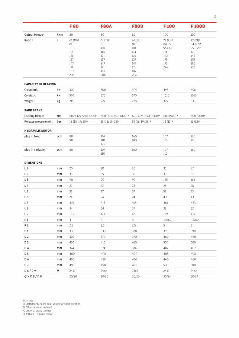
17
F 80 F80A F80B F 100 F 100B
Output torque 2 kNm 80 80 80 100 100
Ratio 3 i 61 (19) 1
81101114121137147171187206
61 (19) 1
81101114121137147171187206
61 (19) 1
81101114121137147171187206
77 (21) 1
84 (22) 1
95 (32) 1
121142175192226
77 (21) 1
84 (22) 1
95 (32) 1
121142175192226
CApACITy OF BEArInG
C-dynamic kN 300 300 300 498 498
Co-static kN 570 570 570 1010 1010
Weight 5 kg 215 227 228 325 338
pArK BrAKE
Locking torque Nm 600 (375; 550; 1000) 4 600 (375; 550; 1000) 4 600 (375; 550; 1000) 4 600 (900) 4 600 (900) 4
Release pressure min. bar 18 (18; 19; 28) 4 18 (18; 19; 28) 4 18 (18; 19; 28) 4 13 (13) 4 13 (13) 4
HyDrAulIC MOTOr
plug in fixed ccm 8090
107110125
160180
107125
160180
plug in variable ccm 80 107110
160 107110
160
DIMEnsIOns
L 1 mm 20 20 20 35 37
L 2 mm 35 35 35 35 37
L 3 mm 90 90 90 165 165
L 4 mm 22 22 22 28 28
L 5 mm 37 37 37 53 53
L 6 mm 24 24 24 43 43
L 7 mm 415 415 415 461 463
L 8 mm 34 34 34 32 32
L 9 mm 123 123 123 139 139
R 1 mm 4 4 4 10/60 12/60
R 2 mm 2.5 2.5 2.5 5 5
D 1 mm 330 330 330 390 390
D 2 mm 370 370 370 460 460
D 3 mm 410 410 410 500 500
D 4 mm 374 374 374 407 407
D 5 mm 400 400 400 408 408
D 6 mm 450 450 450 460 460
D 7 mm 490 490 490 500 500
D 8 / D 9 M 24x2 24x2 24x2 24x2 24x2
Qty. D 8 / D 9 20/20 20/20 20/20 30/24 30/24
1) 2-stage 2) Stated torques are peak values for short duration3) Other ratios on demand 4) Optional brake torques 5) Without Hydraulic motor
18
D3
D2
D1
D3
D6
D2
D1
L6L5L4
L9L8
L7
L9L8
L4 R2L6
L3
L2
L7
L11
L1
L3L2
L1R2R1
D6
D5
D5
D4
D9
D9
D8
D8
D7
D7
L12
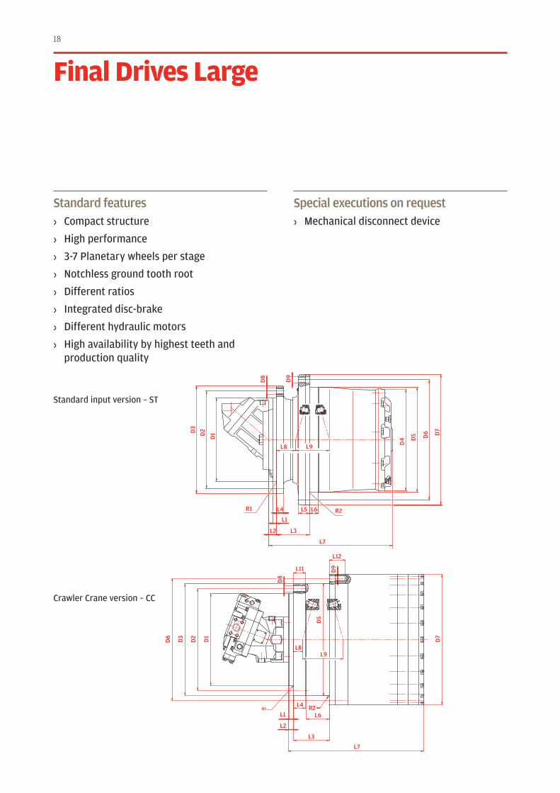
Standard features› Compact structure
› High performance
› 3-7 Planetary wheels per stage
› Notchless ground tooth root
› Different ratios
› Integrated disc-brake
› Different hydraulic motors
› High availability by highest teeth and production quality
Special executions on request› Mechanical disconnect device
Final Drives large
Standard input version – ST
Crawler Crane version – CC
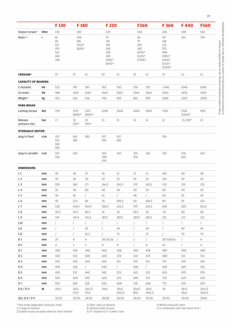
19
Proj
ect r
elat
ed in
stal
latio
n dr
awin
gs c
an b
e m
ade
avai
lble
on
requ
est
as d
imen
sion
s an
d te
chni
cal d
ata
are
subj
ect t
o ch
ange
due
to c
ontin
ues
deve
lopm
ent.
F 130 F 180 F 220 F260 F 360 F 440 F560Output torque 2 kNm 130 180 220 260 360 440 560
Ratio 1 3 i 8185115159167180206
206281(412) 7
(824) 7
97119190248290345(744) 7
(805) 7
6997245345(670) 7
(1115) 7
(1784) 7
94128223257490(385) 7
(446) 7
(1115) 7
(1784) 7
352 739
VErsIOn 5 ST ST CC ST CC ST CC ST CC CC
CApACITy OF BEArInG
C-dynamic kN 523 787 787 765 750 750 750 1 040 1040 1040
Co-static kN 980 1650 1650 1660 1560 1560 1560 2450 2450 2450
Weight 6 kg 452 636 636 740 895 865 895 1080 1300 2000
pArK BrAKE
Locking torque Nm 750 1375 (800) 4
1375 (800) 4
1200 1000 1000 1000 1700 1700 (1000)*
900
Release pressure min.
bar 17 35 (35) 4
35 (35) 4
15 15 15 15 12 15 (7.8)* 13
HyDrAulIC MOTOr
plug in fixed ccm 107125160180
160180
180 107180
107180
355
plug in variable ccm 107160
160 160200250
160 355250
160 355 250160
160
DIMEnsIOns
L 1 mm 45 30 25 18 21 21 21 100 40 40
L 2 mm 45 30 30 52 25 45 25 100 43 43
L 3 mm 190 168 171 166.5 165.5 170 165.5 130 255 255
L 4 mm 35 40 80 40 54 40 54 40 40 45
L 5 mm 58 56 / 61 / 48 / 60 25 45
L 6 mm 45 21.5 86 35 106.5 60 106.5 80 25 120
L 7 mm 530 534.5 564.5 580.5 631.5 579 631.5 658 820 831.5
L 8 mm 50.5 50.3 80.3 16 42 18.5 42 -25 80 80
L 9 mm 147 141.4 141.4 187.5 189.5 189.5 189.5 215 213 213
L10 mm / / / / / / / / / /
L11 mm / / 35 / 54 / 54 / 40 45
L12 mm / / 81.5 / 75 / 75 / 70 70
R 1 mm 25 4 4 35°/16/16 / 2 / 18°/100/16 / 4
R 2 mm 4 3 5 4 4 / 4 10 / 4
D 1 mm 390 450 340 460 428 460 428 580 450 450
D 2 mm 500 510 400 600 474 520 474 680 515 515
D 3 mm 550 560 444 650 521 570 521 735 569 569
D 4 mm 449 528 / 540 / 608 / 649 669 763
D 5 mm 450 535 445 542 523 610 523 650 670 570
D 6 mm 500 600 495 600 570 680 570 720 620 620
D 7 mm 550 650 528 650 608 735 608 775 670 670
D 8 / D 9 M 24x2 24x227x2
33x1.527x2
24x2 30x224x1.5
30x2/Ø33
30x224x1.5
30 36x330x2
36x1.530x1.5
Qty. D 8 / D 9 32/32 30/30 24/30 38/38 30/36 24/24 30/36 30/30 30/30 29/42
* Park brake integrated in hydraulic motor1) 2-stage on demand2) Stated torques are peak values for short duration
3) Other ratios on demand4) Optional brake torques 5) ST= Standard CC= Crawler Crane
5) Without hydraulic motor7) In combination with input bevel drive r
20
D6
D8
D3
D2
D1
D3
D2
D1
D4
D6
D5
D5
D7
D7
D9
D8 D
9
R1
R1 R2
R2
L10L2
L2
L1L4 L5
L6
L1L4
L8L9
L3L7
L10
L8L9
L3L7
L6
L12L11
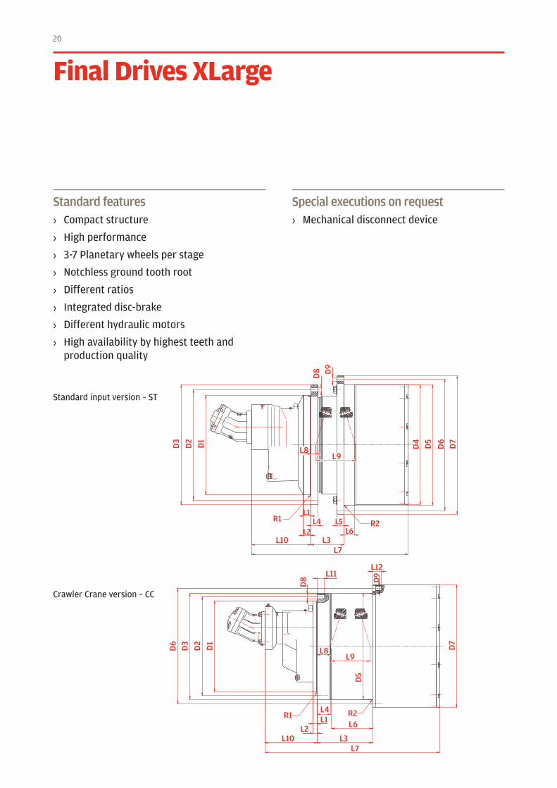
Standard features› Compact structure
› High performance
› 3-7 Planetary wheels per stage
› Notchless ground tooth root
› Different ratios
› Integrated disc-brake
› Different hydraulic motors
› High availability by highest teeth and production quality
Special executions on request› Mechanical disconnect device
Final Drives Xlarge
Standard input version – ST
Crawler Crane version – CC
21
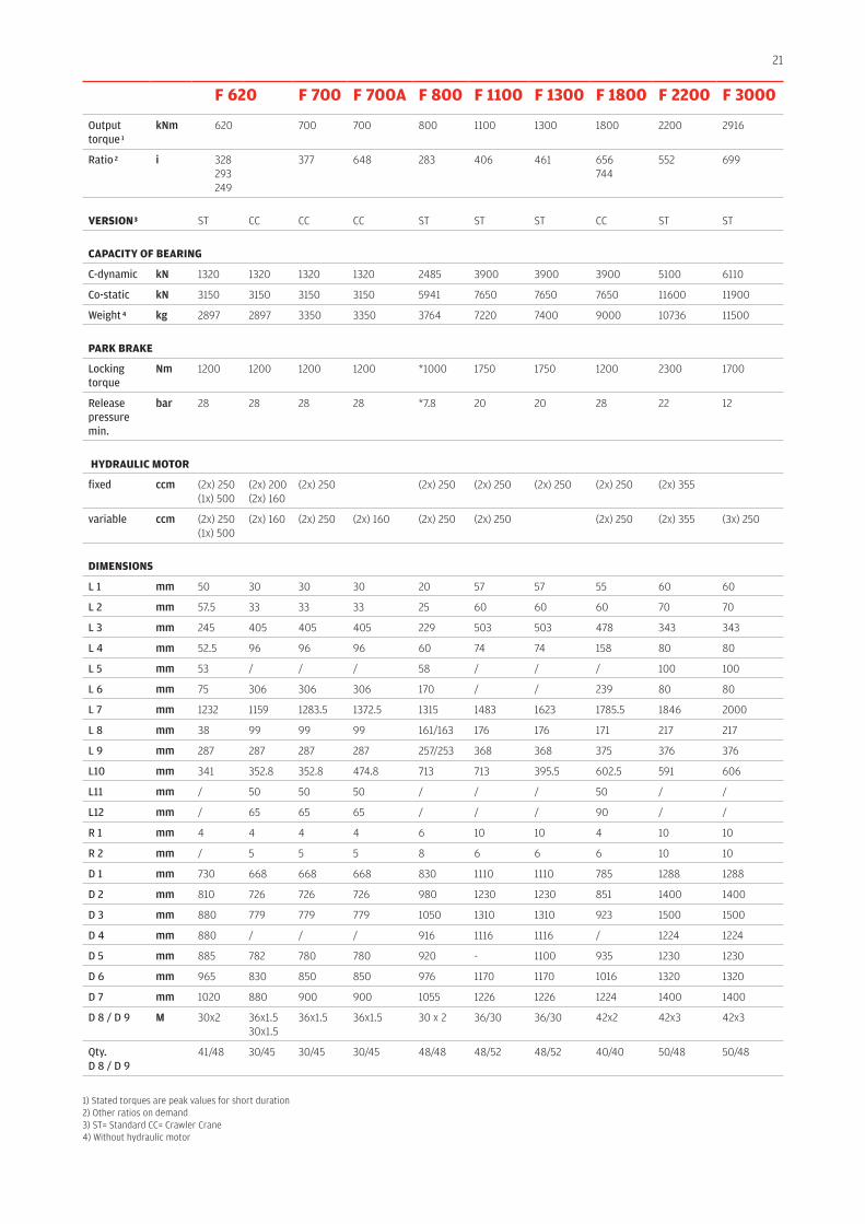
F 620 F 700 F 700A F 800 F 1100 F 1300 F 1800 F 2200 F 3000
Output torque 1
kNm 620 700 700 800 1100 1300 1800 2200 2916
Ratio 2 i 328293249
377 648 283 406 461 656744
552 699
VErsIOn 3 ST CC CC CC ST ST ST CC ST ST
CApACITy OF BEArInG
C-dynamic kN 1320 1320 1320 1320 2485 3900 3900 3900 5100 6110
Co-static kN 3150 3150 3150 3150 5941 7650 7650 7650 11600 11900
Weight 4 kg 2897 2897 3350 3350 3764 7220 7400 9000 10736 11500
pArK BrAKE
Locking torque
Nm 1200 1200 1200 1200 *1000 1750 1750 1200 2300 1700
Release pressure min.
bar 28 28 28 28 *7.8 20 20 28 22 12
HyDrAulIC MOTOr
fixed ccm (2x) 250(1x) 500
(2x) 200(2x) 160
(2x) 250 (2x) 250 (2x) 250 (2x) 250 (2x) 250 (2x) 355
variable ccm (2x) 250(1x) 500
(2x) 160 (2x) 250 (2x) 160 (2x) 250 (2x) 250 (2x) 250 (2x) 355 (3x) 250
DIMEnsIOns
L 1 mm 50 30 30 30 20 57 57 55 60 60
L 2 mm 57.5 33 33 33 25 60 60 60 70 70
L 3 mm 245 405 405 405 229 503 503 478 343 343
L 4 mm 52.5 96 96 96 60 74 74 158 80 80
L 5 mm 53 / / / 58 / / / 100 100
L 6 mm 75 306 306 306 170 / / 239 80 80
L 7 mm 1232 1159 1283.5 1372.5 1315 1483 1623 1785.5 1846 2000
L 8 mm 38 99 99 99 161/163 176 176 171 217 217
L 9 mm 287 287 287 287 257/253 368 368 375 376 376
L10 mm 341 352.8 352.8 474.8 713 713 395.5 602.5 591 606
L11 mm / 50 50 50 / / / 50 / /
L12 mm / 65 65 65 / / / 90 / /
R 1 mm 4 4 4 4 6 10 10 4 10 10
R 2 mm / 5 5 5 8 6 6 6 10 10
D 1 mm 730 668 668 668 830 1110 1110 785 1288 1288
D 2 mm 810 726 726 726 980 1230 1230 851 1400 1400
D 3 mm 880 779 779 779 1050 1310 1310 923 1500 1500
D 4 mm 880 / / / 916 1116 1116 / 1224 1224
D 5 mm 885 782 780 780 920 - 1100 935 1230 1230
D 6 mm 965 830 850 850 976 1170 1170 1016 1320 1320
D 7 mm 1020 880 900 900 1055 1226 1226 1224 1400 1400
D 8 / D 9 M 30x2 36x1.530x1.5
36x1.5 36x1.5 30 x 2 36/30 36/30 42x2 42x3 42x3
Qty. D 8 / D 9
41/48 30/45 30/45 30/45 48/48 48/52 48/52 40/40 50/48 50/48
1) Stated torques are peak values for short duration2) Other ratios on demand3) ST= Standard CC= Crawler Crane4) Without hydraulic motor
22
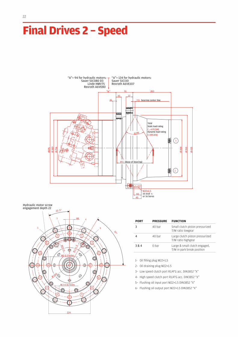
“A”= 94 for hydraulic motors:Sauer 51C080 D3
Linde HMV75Rexroth A6VE80
“A”= 124 for hydraulic motors:Sauer 51C110Rexroth A6VE107
M20x1.516 stud sor 16 bores
1
2
Ø37
5
Ø29
6
Ø30
0
4540
60∞
193 (Base of bearing)
20391"A "
30
15 7.5 bearing center line
37
Ø35
0
Ø43
5
Ø30
4
TotalStatic load ratingC °=670 [kN]Dynamic load ratingC=395 [kN]
Hydraulic motor screwengagement depth 22
5
3 4
6
2 holes
R137.5
R1 3
1 .5
Ø 340
M2 0
M 2 0 16 holes
224
44
22. 5°
57 °
Final Drives 2 – speed
1– Oil filling plug M22×1.5
2– Oil draining plug M22×1.5
3– Low speed clutch port R1/4"G acc. DIN3852 “X”
4– High speed clutch port R1/4"G acc. DIN3852 “X”
5– Flushing oil input port M22×1.5 DIN3852 “X”
6– Flushing oil output port M22×1.5 DIN3852 “X”
pOrT prEssurE FunCTIOn
3 40 bar Small clutch piston pressurized T/M ratio lowgear
4 40 bar Large clutch piston pressurized T/M ratio highgear
3 & 4 0 bar Large & small clutch engaged, T/M in park break position
23
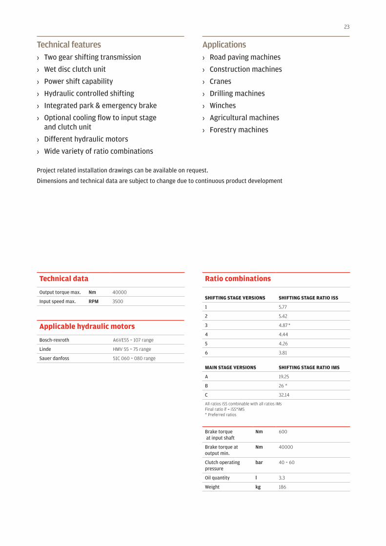
Technical features› Two gear shifting transmission
› Wet disc clutch unit
› Power shift capability
› Hydraulic controlled shifting
› Integrated park & emergency brake
› Optional cooling flow to input stage and clutch unit
› Different hydraulic motors
› Wide variety of ratio combinations
Applications› Road paving machines
› Construction machines
› Cranes
› Drilling machines
› Winches
› Agricultural machines
› Forestry machines
Project related installation drawings can be available on request.
Dimensions and technical data are subject to change due to continuous product development
Technical data
Output torque max. Nm 40000
Input speed max. RPM 3500
Applicable hydraulic motors
Bosch-rexroth A6VE55 ~ 107 range
Linde HMV 55 ~ 75 range
Sauer danfoss 51C 060 ~ 080 range
ratio combinations
sHIFTInG sTAGE VErsIOns sHIFTInG sTAGE rATIO Iss
1 5.77
2 5.42
3 4.87 *
4 4.44
5 4.26
6 3.81
MAIn sTAGE VErsIOns sHIFTInG sTAGE rATIO IMs
A 19.25
B 26 *
C 32.14
All ratios iSS combinable with all ratios iMsFinal ratio if = iSS*iMS* Preferred ratios
Brake torque at input shaft
Nm 600
Brake torque at output min.
Nm 40000
Clutch operating pressure
bar 40 ~ 60
Oil quantity l 3.3
Weight kg 186
24
D6
D7
D5
D4
D6
D5
D4
D8
D9
D2
D2
D1
D1
D3
D9
D8
D3
D7
L1
L10
L8 L9
L6
R2R1
L2
L1L2
L4 L3
L5
L5L4L5
L7
L7
L6
L6
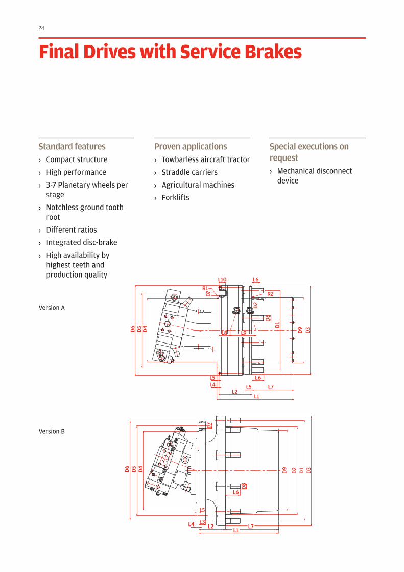
Standard features› Compact structure
› High performance
› 3-7 Planetary wheels per stage
› Notchless ground tooth root
› Different ratios
› Integrated disc-brake
› High availability by highest teeth and production quality
Proven applications› Towbarless aircraft tractor
› Straddle carriers
› Agricultural machines
› Forklifts
Special executions on request› Mechanical disconnect
device
Final Drives with service Brakes
Version A
Version B
25
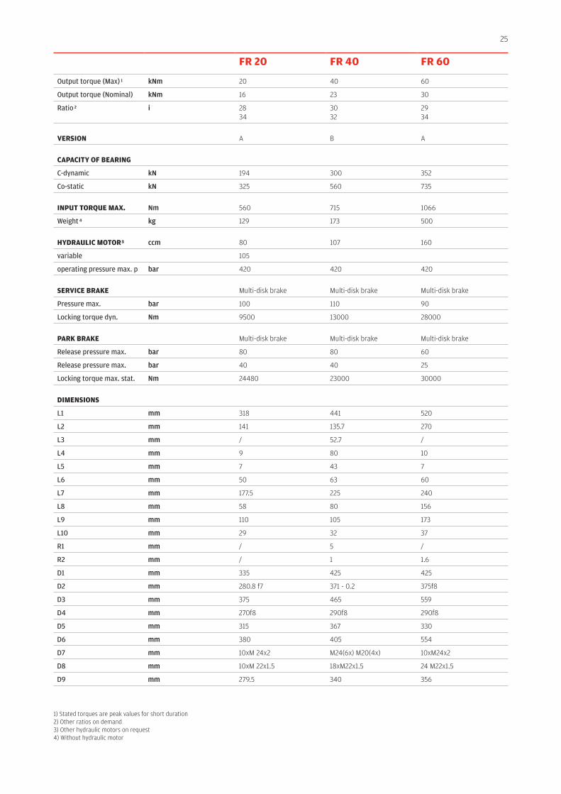
Fr 20 Fr 40 Fr 60
Output torque (Max) 1 kNm 20 40 60
Output torque (Nominal) kNm 16 23 30
Ratio 2 i 2834
3032
2934
VErsIOn A B A
CApACITy OF BEArInG
C-dynamic kN 194 300 352
Co-static kN 325 560 735
InpuT TOrquE MAX. Nm 560 715 1066
Weight 4 kg 129 173 500
HyDrAulIC MOTOr 3 ccm 80 107 160
variable 105
operating pressure max. p bar 420 420 420
sErVICE BrAKE Multi-disk brake Multi-disk brake Multi-disk brake
Pressure max. bar 100 110 90
Locking torque dyn. Nm 9500 13000 28000
pArK BrAKE Multi-disk brake Multi-disk brake Multi-disk brake
Release pressure max. bar 80 80 60
Release pressure max. bar 40 40 25
Locking torque max. stat. Nm 24480 23000 30000
DIMEnsIOns
L1 mm 318 441 520
L2 mm 141 135.7 270
L3 mm / 52.7 /
L4 mm 9 80 10
L5 mm 7 43 7
L6 mm 50 63 60
L7 mm 177.5 225 240
L8 mm 58 80 156
L9 mm 110 105 173
L10 mm 29 32 37
R1 mm / 5 /
R2 mm / 1 1.6
D1 mm 335 425 425
D2 mm 280.8 f7 371 - 0.2 375f8
D3 mm 375 465 559
D4 mm 270f8 290f8 290f8
D5 mm 315 367 330
D6 mm 380 405 554
D7 mm 10xM 24x2 M24(6x) M20(4x) 10xM24x2
D8 mm 10xM 22x1.5 18xM22x1.5 24 M22x1.5
D9 mm 279.5 340 356
1) Stated torques are peak values for short duration2) Other ratios on demand3) Other hydraulic motors on request4) Without hydraulic motor
28
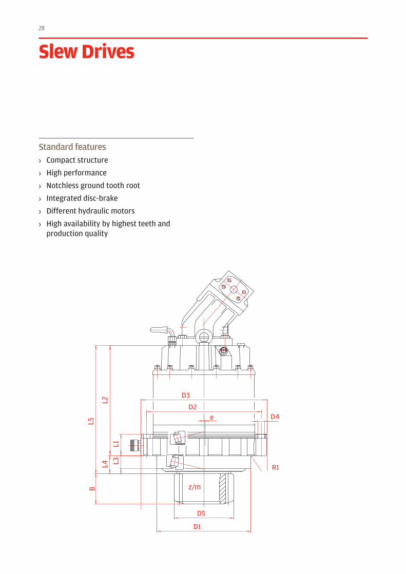
slew Drives
D5
D3
D4
D1
D2
L1L3L4
e
L5B
L2
z/m
R1
Standard features› Compact structure
› High performance
› Notchless ground tooth root
› Integrated disc-brake
› Different hydraulic motors
› High availability by highest teeth and production quality
29
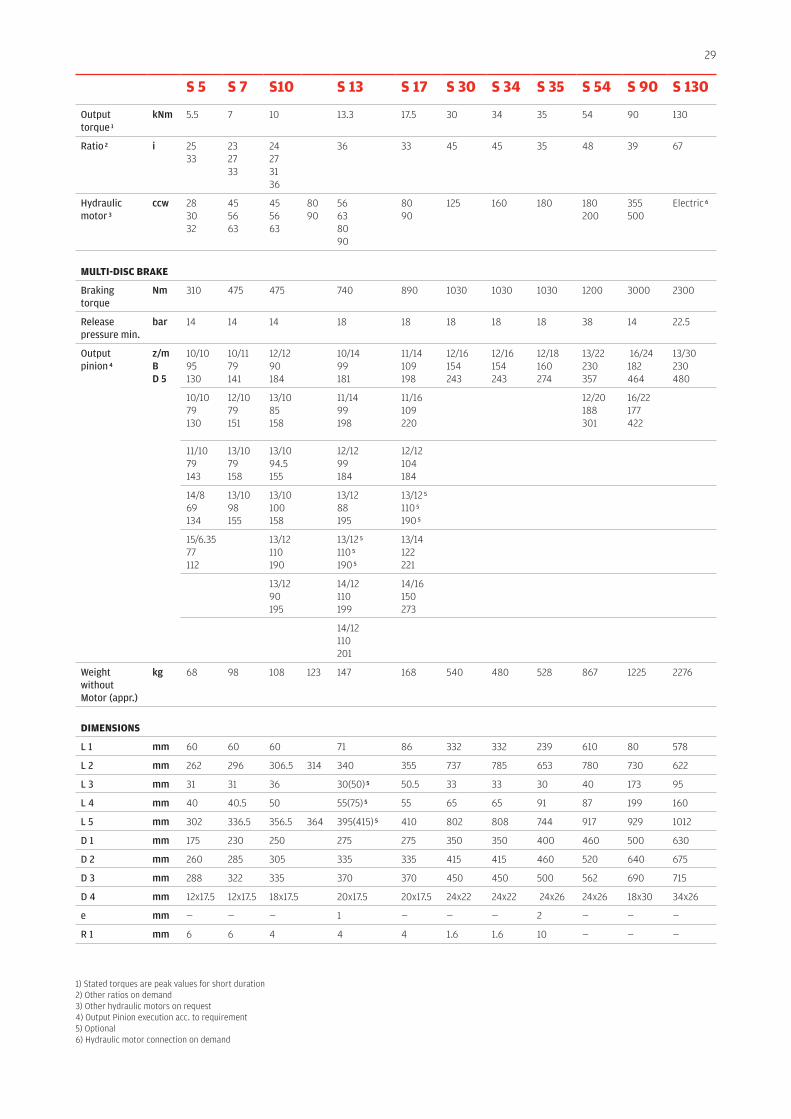
s 5 s 7 s10 s 13 s 17 s 30 s 34 s 35 s 54 s 90 s 130
Output torque 1
kNm 5.5 7 10 13.3 17.5 30 34 35 54 90 130
Ratio 2 i 2533
232733
24273136
36 33 45 45 35 48 39 67
Hydraulic motor 3
ccw 283032
455663
45 5663
80 90
56638090
8090
125 160 180 180200
355500
Electric 6
MulTI-DIsC BrAKE
Braking torque
Nm 310 475 475 740 890 1030 1030 1030 1200 3000 2300
Release pressure min.
bar 14 14 14 18 18 18 18 18 38 14 22.5
Output pinion 4
z/mBD 5
10/1095130
10/1179141
12/1290184
10/1499181
11/14109198
12/16154243
12/16154243
12/18160274
13/22230357
16/24182464
13/30230480
10/1079130
12/1079151
13/1085158
11/1499198
11/16109220
12/20188301
16/22177422
11/1079143
13/1079158
13/1094.5155
12/1299184
12/12104184
14/869134
13/1098155
13/10100158
13/1288195
13/12 5
110 5
190 5
15/6.3577112
13/12110190
13/12 5
110 5
190 5
13/14122221
13/1290195
14/12110199
14/16150273
14/12110201
Weight without Motor (appr.)
kg 68 98 108 123 147 168 540 480 528 867 1225 2276
DIMEnsIOns
L 1 mm 60 60 60 71 86 332 332 239 610 80 578
L 2 mm 262 296 306.5 314 340 355 737 785 653 780 730 622
L 3 mm 31 31 36 30(50) 5 50.5 33 33 30 40 173 95
L 4 mm 40 40.5 50 55(75) 5 55 65 65 91 87 199 160
L 5 mm 302 336.5 356.5 364 395(415) 5 410 802 808 744 917 929 1012
D 1 mm 175 230 250 275 275 350 350 400 460 500 630
D 2 mm 260 285 305 335 335 415 415 460 520 640 675
D 3 mm 288 322 335 370 370 450 450 500 562 690 715
D 4 mm 12x17.5 12x17.5 18x17.5 20x17.5 20x17.5 24x22 24x22 24x26 24x26 18x30 34x26
e mm — — — 1 — — — 2 — — —
R 1 mm 6 6 4 4 4 1.6 1.6 10 — — —
1) Stated torques are peak values for short duration2) Other ratios on demand3) Other hydraulic motors on request4) Output Pinion execution acc. to requirement5) Optional 6) Hydraulic motor connection on demand
32
D3
D2
D1
D3
D2
D1
D10
D11
D12 D4
D6
D7
D4
D6
D7
D13
D8
D9
D5
L7
L3
L4
L4
L7L3
L5L6
L5 L6
L9L8
D5
L9L8
L11
D8
D9
L11
L1
L2
L1
L2
L10
Standard features› Compact structure
› High performance
› Notchless ground tooth root
› Different ratios
› Suitable for various hydraulic motors
› High availability by highest teeth and production quality
Special executions on request
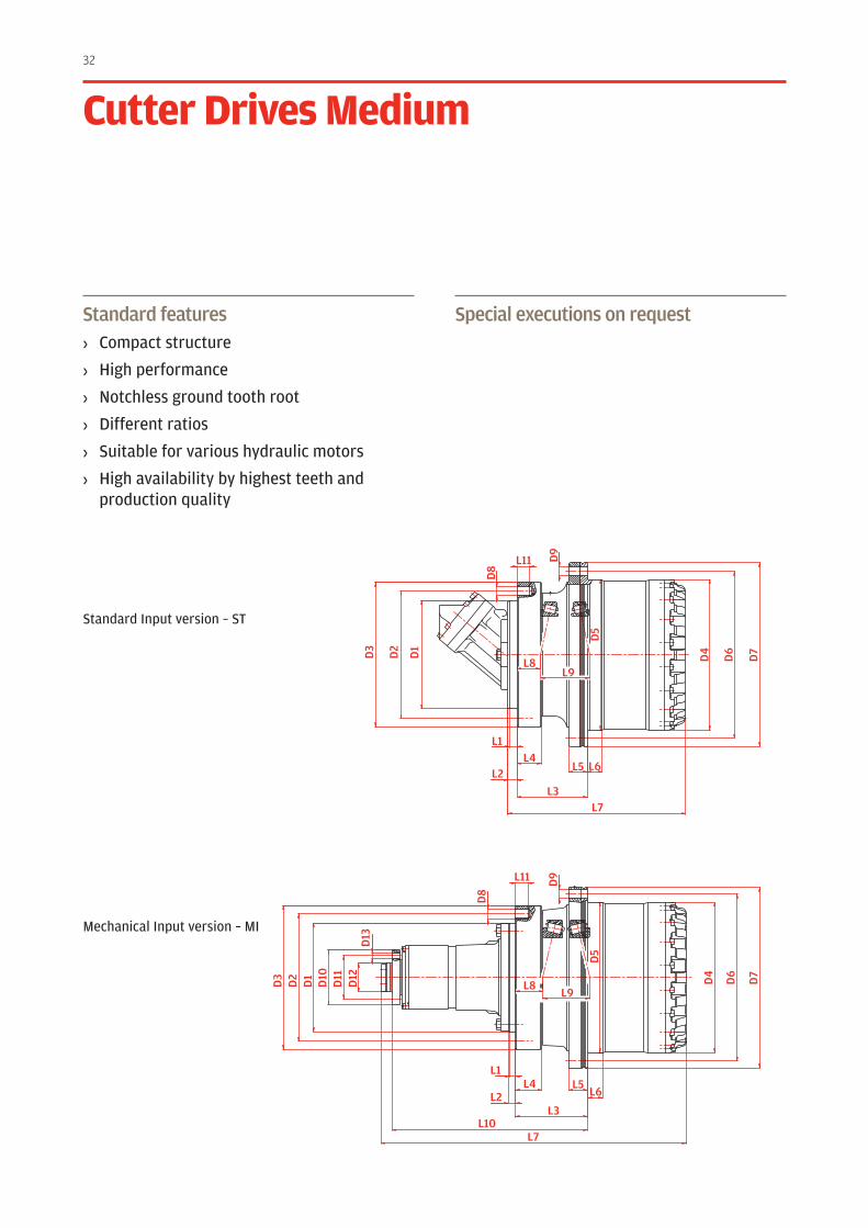
Cutter Drives Medium
Standard Input version – ST
Mechanical Input version – MI
33
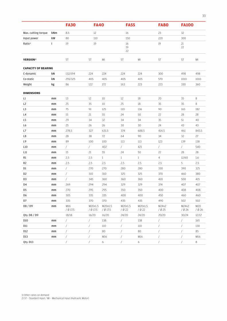
FA30 FA40 FA55 FA80 FA100
Max. cutting torque kNm 8.5 12 16 23 32
Input power kW 80 110 150 220 300
Ratio 1 i 19 19 16 1922
19 2122
VErsIOn 2 ST ST MI ST MI ST ST MI
CApACITy OF BEArInG
C-dynamic kN 132/194 224 224 224 224 300 498 498
Co-static kN 255/325 405 405 405 405 570 1010 1010
Weight kg 86 122 172 163 223 223 330 360
DIMEnsIOns
L1 mm 13 12 10 12 18 20 35 8
L2 mm 25 35 10 25 18 35 35 8
L3 mm 75 91 125 110 136 90 165 182
L4 mm 15 21 55 24 50 22 28 28
L5 mm 29 34 32 34 34 35 51 40
L6 mm 25 26 26 30 30 24 43 43
L7 mm 278.5 327 631.5 374 688.5 414.5 461 843.5
L8 mm 28 38 72 64 90 34 32 27
L9 mm 89 100 100 113 113 123 139 138
L10 mm / / 402 / 421 / / 540
L11 mm 15 21 55 24 50 22 28 28
R1 mm 2.5 2.5 1 1 1 4 12/60 1.6
R2 mm 2.5 2.5 2.5 2.5 2.5 2.5 5 2.5
D1 mm / 270 270 280 280 330 390 325
D2 mm / 310 310 325 325 370 460 380
D3 mm / 345 360 360 360 410 500 415
D4 mm 269 294 294 329 329 374 407 407
D5 mm 270 295 295 350 350 400 408 408
D6 mm 305 335 335 400 400 450 460 460
D7 mm 335 370 370 435 435 490 502 502
D8 / D9 mm M16 / Ø 17.5
M20x1.5 / Ø 17.5
M20x1.5 / Ø 17.5
M20x1.5/ Ø 22
M20x1.5/ Ø 22
M24x2/ Ø 25
M24x2 / Ø 26
M20/ Ø 26
Qty. D8 / D9 18/18 16/20 16/20 24/20 24/20 20/20 30/24 12/12
D10 mm / / 138 / 138 / / 165
D11 mm / / 110 / 110 / / 130
D12 mm / / 80 / 80 / / 85
D13 mm / / M16 / M16 / / M16
Qty. D13 / / 6 / 6 / / 8
1) Other ratios on demand2) ST – Standard Input / MI – Mechanical Input (Hydraulic Motor)
34
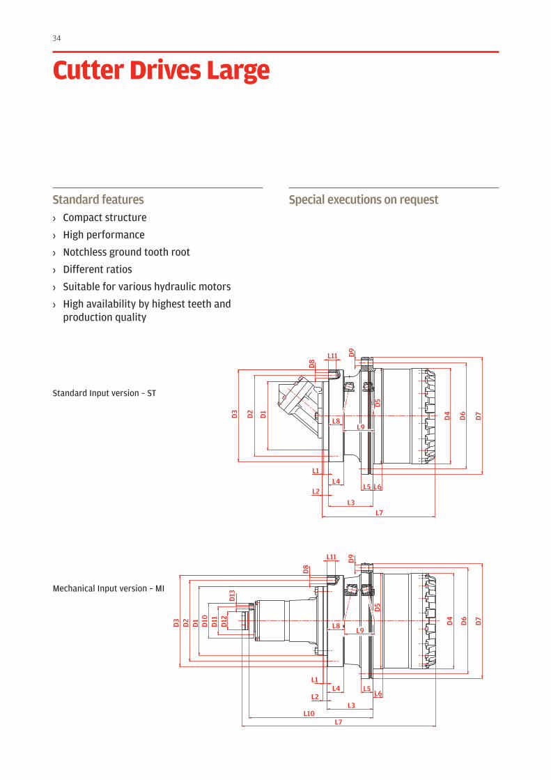
Standard features› Compact structure
› High performance
› Notchless ground tooth root
› Different ratios
› Suitable for various hydraulic motors
› High availability by highest teeth and production quality
Special executions on request
Cutter Drives large
D3
D2
D1
D3
D2
D1
D10
D11
D12 D4
D6
D7
D4
D6
D7
D13
D8
D9
D5
L7
L3
L4
L4
L7L3
L5L6
L5 L6
L9L8
D5
L9L8
L11
D8
D9
L11
L1
L2
L1
L2
L10
Standard Input version – ST
Mechanical Input version – MI
35
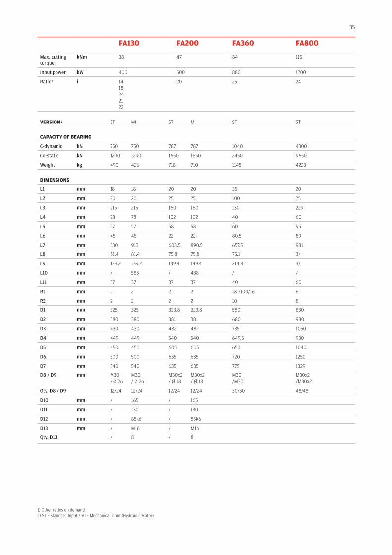
FA130 FA200 FA360 FA800
Max. cutting torque
kNm 38 47 84 115
Input power kW 400 500 880 1200
Ratio 1 i 14 18 2421 22
20 25 24
VErsIOn 2 ST MI ST MI ST ST
CApACITy OF BEArInG
C-dynamic kN 750 750 787 787 1040 4300
Co-static kN 1290 1290 1650 1650 2450 9650
Weight kg 490 426 718 710 1145 4223
DIMEnsIOns
L1 mm 18 18 20 20 35 20
L2 mm 20 20 25 25 100 25
L3 mm 215 215 160 160 130 229
L4 mm 78 78 102 102 40 60
L5 mm 57 57 58 58 60 95
L6 mm 45 45 22 22 80.5 89
L7 mm 530 913 603.5 890.5 657.5 981
L8 mm 81.4 81.4 75.8 75.8 75.1 3)
L9 mm 139.2 139.2 149.4 149.4 214.8 3)
L10 mm / 585 / 438 / /
L11 mm 37 37 37 37 40 60
R1 mm 2 2 2 2 18°/100/16 6
R2 mm 2 2 2 2 10 8
D1 mm 325 325 323.8 323.8 580 830
D2 mm 380 380 381 381 680 980
D3 mm 430 430 482 482 735 1050
D4 mm 449 449 540 540 649.5 930
D5 mm 450 450 605 605 650 1040
D6 mm 500 500 635 635 720 1250
D7 mm 540 540 635 635 775 1329
D8 / D9 mm M30/ Ø 26
M30/ Ø 26
M30x2/ Ø 18
M30x2/ Ø 18
M30/M30
M30x2/M30x2
Qty. D8 / D9 12/24 12/24 12/24 12/24 30/30 48/48
D10 mm / 165 / 165
D11 mm / 130 / 130
D12 mm / 85k6 / 85k6
D13 mm / M16 / M16
Qty. D13 / 8 / 8
1) Other ratios on demand2) ST – Standard Input / MI – Mechanical Input (Hydraulic Motor)
36
D9
D7
D4
D6
D5
L5 L6
L3
L10
L7
L1
L8
L9
L4
D14
R1
D1
D8
L11
L2
D12
D11
D13
D2
D3
FLUSHING PORTOIL OUT
SHIFTING PORT50 bar
FLUSHING PORTOIL IN
D10
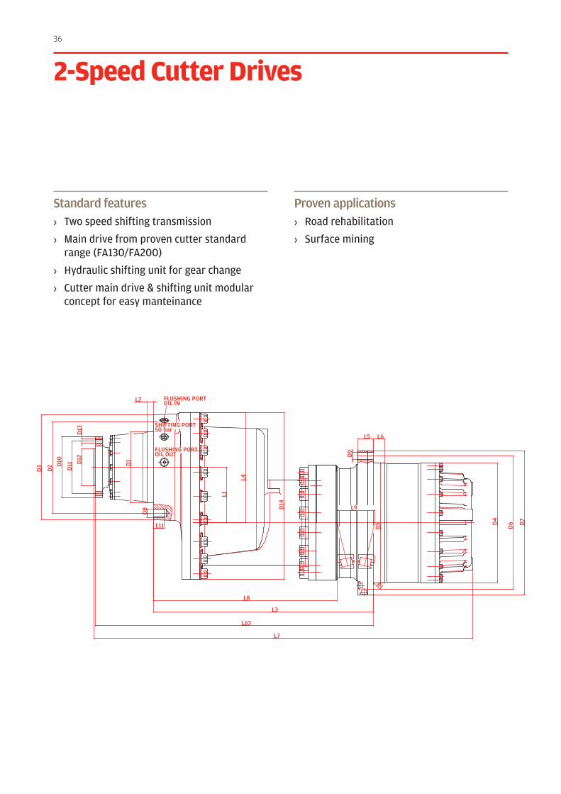
Standard features› Two speed shifting transmission
› Main drive from proven cutter standard range (FA130/FA200)
› Hydraulic shifting unit for gear change
› Cutter main drive & shifting unit modular concept for easy manteinance
Proven applications› Road rehabilitation
› Surface mining
2-speed Cutter Drives
37
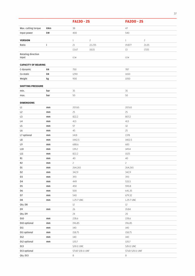
FA130 - 2s FA200 - 2s
Max. cutting torque kNm 38 47
Input power kW 400 540
VErsIOn 1 2 1 2
Ratio i 21 22.235 19.877 21.05
13.67 18.01 13 17.05
Rotating direction input ccw ccw
CApACITy OF BEArInG
C-dynamic kN 750 787
Co-static kN 1290 1650
Weight kg 900 1050
sHIFTInG prEssurE
min. bar 35 35
max. bar 50 50
DIMEnsIOns
L1 mm 207.65 207.65
L2 mm 25 25
L3 mm 822.2 807.2
L4 mm 413 413
L5 mm 57 32
L6 mm 45 25
L7 optional mm 1418 1378
L8 mm 1442.5 1402.5
L9 mm 688.6 683
L10 mm 139.2 149.4
L11 mm 822.2 1025
R1 mm 40 40
R2 mm 2 2
D1 mm 264.265 264.265
D2 mm 342.9 342.9
D3 mm 393 393
D4 mm 449 533.5
D5 mm 450 590.8
D6 mm 500 641.35
D7 mm 540 679.32
D8 mm 1.25-7 UNC 1.25-7 UNC
Qty. D8 12 12
D9 mm 26 19.84
Qty. D9 24 20
D10 mm 228.6 228.6
D10 optional mm 196.85 196.85
D11 mm 140 140
D11 optional mm 158.75 158.75
D12 mm 140 140
D12 optional mm 120.7 120.7
D13 5/8-11 UNC 5/8-11 UNC
D13 optional STUD 5/8-11 UNF STUD 5/8-11 UNF
Qty. D13 8 8
40
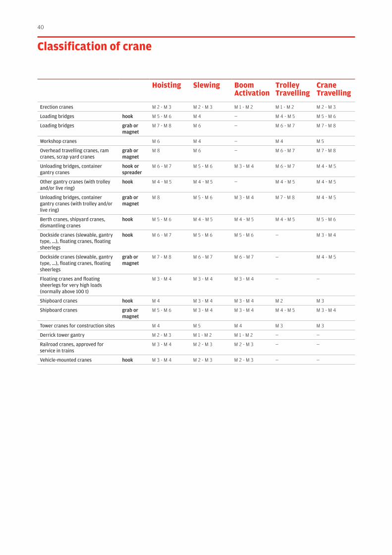
Hoisting slewing Boom Activation
Trolley Travelling
Crane Travelling
Erection cranes M 2 - M 3 M 2 - M 3 M 1 - M 2 M 1 - M 2 M 2 - M 3
Loading bridges hook M 5 - M 6 M 4 — M 4 - M 5 M 5 - M 6
Loading bridges grab or magnet
M 7 - M 8 M 6 — M 6 - M 7 M 7 - M 8
Workshop cranes M 6 M 4 — M 4 M 5
Overhead travelling cranes, ram cranes, scrap yard cranes
grab or magnet
M 8 M 6 — M 6 - M 7 M 7 - M 8
Unloading bridges, container gantry cranes
hook or spreader
M 6 - M 7 M 5 - M 6 M 3 - M 4 M 6 - M 7 M 4 - M 5
Other gantry cranes (with trolley and/or live ring)
hook M 4 - M 5 M 4 - M 5 — M 4 - M 5 M 4 - M 5
Unloading bridges, container gantry cranes (with trolley and/or live ring)
grab or magnet
M 8 M 5 - M 6 M 3 - M 4 M 7 - M 8 M 4 - M 5
Berth cranes, shipyard cranes, dismantling cranes
hook M 5 - M 6 M 4 - M 5 M 4 - M 5 M 4 - M 5 M 5 - M 6
Dockside cranes (slewable, gantry type, …), floating cranes, floating sheerlegs
hook M 6 - M 7 M 5 - M 6 M 5 - M 6 — M 3 - M 4
Dockside cranes (slewable, gantry type, …), floating cranes, floating sheerlegs
grab or magnet
M 7 - M 8 M 6 - M 7 M 6 - M 7 — M 4 - M 5
Floating cranes and floating sheerlegs for very high loads (normally above 100 t)
M 3 - M 4 M 3 - M 4 M 3 - M 4 — —
Shipboard cranes hook M 4 M 3 - M 4 M 3 - M 4 M 2 M 3
Shipboard cranes grab or magnet
M 5 - M 6 M 3 - M 4 M 3 - M 4 M 4 - M 5 M 3 - M 4
Tower cranes for construction sites M 4 M 5 M 4 M 3 M 3
Derrick tower gantry M 2 - M 3 M 1 - M 2 M 1 - M 2 — —
Railroad cranes, approved for service in trains
M 3 - M 4 M 2 - M 3 M 2 - M 3 — —
Vehicle-mounted cranes hook M 3 - M 4 M 2 - M 3 M 2 - M 3 — —
Classification of crane
41
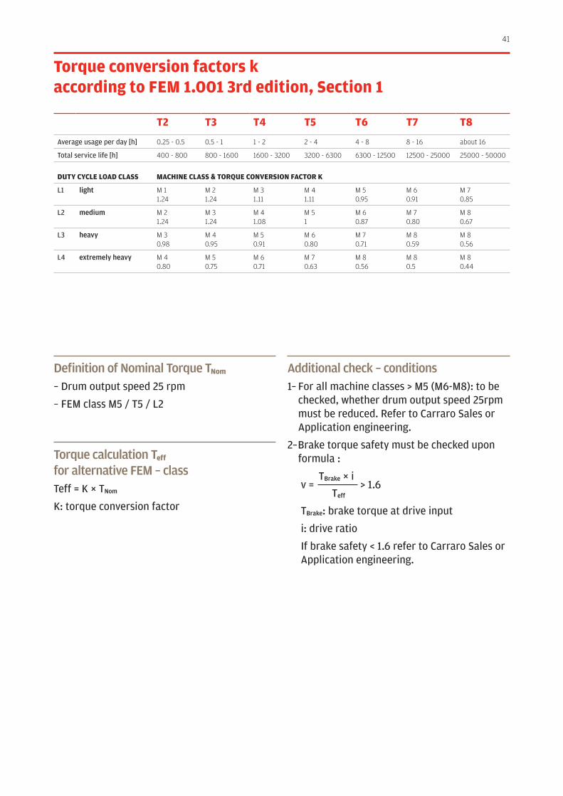
Torque conversion factors k according to FEM 1.001 3rd edition, section 1
T2 T3 T4 T5 T6 T7 T8
Average usage per day [h] 0.25 - 0.5 0.5 - 1 1 - 2 2 - 4 4 - 8 8 - 16 about 16
Total service life [h] 400 - 800 800 - 1600 1600 - 3200 3200 - 6300 6300 - 12500 12500 - 25000 25000 - 50000
DuTy CyClE lOAD ClAss MACHInE ClAss & TOrquE COnVErsIOn FACTOr K
L1 light M 11.24
M 21.24
M 31.11
M 41.11
M 50.95
M 60.91
M 70.85
L2 medium M 21.24
M 31.24
M 41.08
M 51
M 60.87
M 70.80
M 80.67
L3 heavy M 30.98
M 40.95
M 50.91
M 60.80
M 70.71
M 80.59
M 80.56
L4 extremely heavy M 40.80
M 50.75
M 60.71
M 70.63
M 80.56
M 80.5
M 80.44
Definition of Nominal Torque Tnom
– Drum output speed 25 rpm
– FEM class M5 / T5 / L2
Torque calculation Teff for alternative FEM – class Teff = K × TNom
K: torque conversion factor
Additional check – conditions1– For all machine classes > M5 (M6-M8): to be
checked, whether drum output speed 25rpm must be reduced. Refer to Carraro Sales or Application engineering.
2– Brake torque safety must be checked upon formula :
TBrake × i v = > 1.6 Teff
TBrake: brake torque at drive input
i: drive ratio
If brake safety < 1.6 refer to Carraro Sales or Application engineering.
42
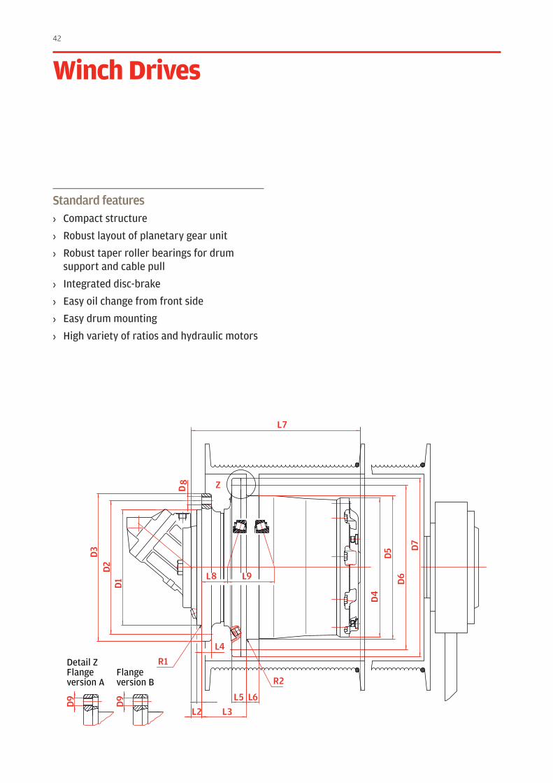
Standard features› Compact structure
› Robust layout of planetary gear unit
› Robust taper roller bearings for drum support and cable pull
› Integrated disc-brake
› Easy oil change from front side
› Easy drum mounting
› High variety of ratios and hydraulic motors
Winch Drives
D1
D2
D3
D6
D7
L2
R1
R2
L7
L
Z
8 L9
D4
L3
D9
D9
D8
L4
L5 L6
D5
Detail ZFlange version A
Flange version B
43
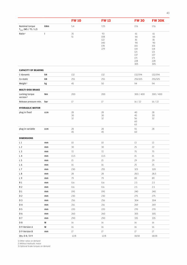
1) Other ratios on demand2) Without Hydraulic motor3) Optional brake torques on demand
FW 10 FW 13 FW 30 FW 30KNominal torqueTNom (M5 / T5 / L2)
kNm 5.4 7.25 17.6 17.6
Ratio 1 i 3551
93 108122140178229
61 66 81 90101114121137171228305
61 66 81 90101114121137171228305
CApACITy OF BEArInG
C-dynamic kN 132 132 132/194 132/194
Co-static kN 255 255 255/325 255/325
Weight 2 kg 45 50 94 94
MulTI-DIsK BrAKE
Locking torque version 3
Nm 200 200 300 / 400 300 / 400
Release pressure min. bar 17 17 16 / 22 16 / 22
HyDrAulIC MOTOr
plug in fixed ccm 283032
283032
4045566063
283032
plug in variable ccm 2845
2845
5560
28
DIMEnsIOns
L 1 mm 10 10 13 13
L 2 mm 30 30 25 22
L 3 mm 72 72 75 75
L 4 mm 13.5 13.5 15 15
L 5 mm 15 15 29 29
L 6 mm 16 16 25 25
L 7 mm 230 255 323 320
L 8 mm 28 28 28.5 28.5
L 9 mm 79 79 89 89
R 1 mm 0.6 0.6 2.5 2.5
R 2 mm 0.6 0.6 2.5 2.5
D 1 mm 190 190 240 240
D 2 mm 230 230 275 275
D 3 mm 256 256 304 304
D 4 mm 216 216 269 269
D 5 mm 220 220 270 270
D 6 mm 260 260 305 305
D 7 mm 290 290 335 335
D 8 M 16 16 16 16
D 9 Version A M 16 16 16 16
D 9 Version B mm 17 17 17 17
Qty. D 8 / D 9 12/8 12/8 18/18 18/18

44
Standard features› Compact structure
› Robust layout of planetary gear unit
› Robust taper roller bearings for drum support and cable pull
› Integrated disc-brake
› Easy oil change from front side
› Easy drum mounting
› High variety of ratios and hydraulic motors
Winch Drives
D1
D2
D3
D6
D7
L2
R1
R2
L7
L
Z
8 L9
D4
L3
D9
D9
D8
L4
L5 L6
D5
Detail ZFlange version A
Flange version B
45
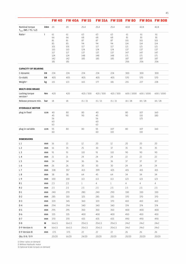
1) Other ratios on demand2) Without Hydraulic motor3) Optional brake torques on demand
FW 40 FW 40A FW 55 FW 55A FW 55B FW 80 FW 80A FW 80B
Nominal torqueTNom (M5 / T5 / L2)
kNm 20 20 25.4 25.4 25.4 42.8 42.8 42.8
Ratio 1 i 61 66 81 85 101 110 117 124 142 181
61 66 81 85 101 110 117 124 142 181
63 68 87 94 117124 137 148 185
63 68 87 94 117124 137 148 185
63 68 87 94 117124 137 148 185
61 81101114121137147171187206
61 81101114121137147171187206
61 81101114121137147171187206
CApACITy OF BEArInG
C-dynamic kN 224 224 224 224 224 300 300 300
Co-static kN 405 405 405 405 405 570 570 570
Weight 2 kg 115 123 165 177 181 215 227 228
MulTI-DIsK BrAKE
Locking torque version 3
Nm 420 420 420 / 500 420 / 500 420 / 500 600 / 1000 600 / 1000 600 / 1000
Release pressure min. bar 18 18 15 / 21 15 / 21 15 / 21 18 / 28 18 / 28 18 / 28
HyDrAulIC MOTOr
plug in fixed ccm 4045566063
8090
8090
4045566063
8090
107110125
160180
plug in variable ccm 5560
80 80 5560
107110
80 107110
160
DIMEnsIOns
L 1 mm 16 13 12 20 12 20 20 20
L 2 mm 16 35 25 30 37 35 35 35
L 3 mm 91 91 110 91 110 90 90 90
L 4 mm 21 21 24 24 24 22 22 22
L 5 mm 34 34 36 36 36 37 37 37
L 6 mm 26 26 30 30 30 24 24 24
L 7 mm 338 357 413 399 425 415 415 415
L 8 mm 38 38 64 45 64 34 34 34
L 9 mm 100 100 113 113 113 123 123 123
R 1 mm 2.5 2.5 1 4 1 4 4 4
R 2 mm 2.5 2.5 2.5 2.5 2.5 2.5 2.5 2.5
D 1 mm 240 270 280 240 290 330 330 330
D 2 mm 285 310 325 285 335 370 370 370
D 3 mm 320 345 360 320 370 410 410 410
D 4 mm 294 294 340 340 340 374 374 374
D 5 mm 295 295 350 350 350 400 400 400
D 6 mm 335 335 400 400 400 450 450 450
D 7 mm 370 370 435 435 435 490 490 490
D 8 M 16x1.5 16x1.5 20x1.5 20x1.5 20x1.5 24x2 24x2 24x2
D 9 Version A M 16x1.5 16x1.5 20x1.5 20x1.5 20x1.5 24x2 24x2 24x2
D 9 Version B mm 17.5 17.5 22 22 22 26 26 26
Qty. D 8 / D 9 20/20 16/20 24/20 20/20 20/20 20/20 20/20 20/20

46
Standard features› Compact structure
› Robust layout of planetary gear unit
› Robust taper roller bearings for drum support and cable pull
› Integrated disc-brake
› Easy oil change from front side
› Easy drum mounting
› High variety of ratios and hydraulic motors
Winch Drives
D1
D2
D3
D6
D7
L2
R1
R2
L7
L
Z
8 L9
D4
L3
D9
D9
D8
L4
L5 L6
D5
Detail ZFlange version A
Flange version B
47
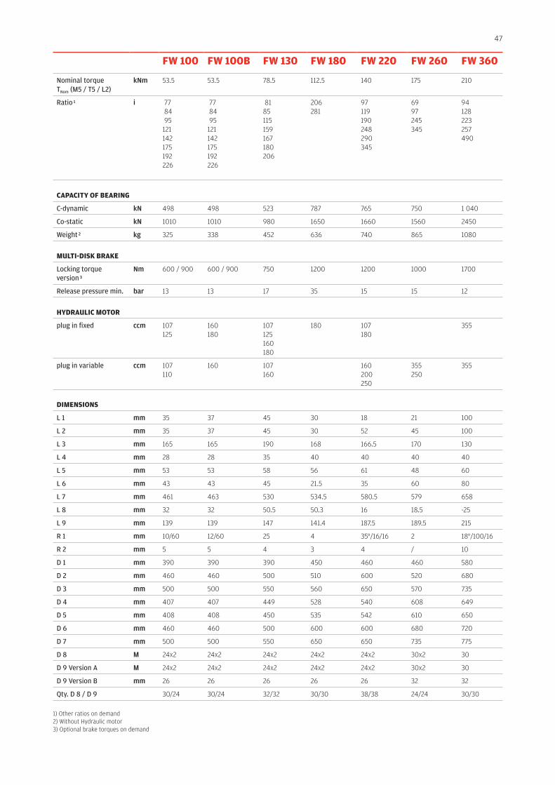
1) Other ratios on demand2) Without Hydraulic motor3) Optional brake torques on demand
FW 100 FW 100B FW 130 FW 180 FW 220 FW 260 FW 360
Nominal torqueTNom (M5 / T5 / L2)
kNm 53.5 53.5 78.5 112.5 140 175 210
Ratio 1 i 77 84 95 121142175192226
77 84 95 121142175192226
8185115159167180206
206281
97119190248290345
6997245345
94128223257490
CApACITy OF BEArInG
C-dynamic kN 498 498 523 787 765 750 1 040
Co-static kN 1010 1010 980 1650 1660 1560 2450
Weight 2 kg 325 338 452 636 740 865 1080
MulTI-DIsK BrAKE
Locking torque version 3
Nm 600 / 900 600 / 900 750 1200 1200 1000 1700
Release pressure min. bar 13 13 17 35 15 15 12
HyDrAulIC MOTOr
plug in fixed ccm 107125
160180
107125160180
180 107180
355
plug in variable ccm 107110
160 107160
160200250
355250
355
DIMEnsIOns
L 1 mm 35 37 45 30 18 21 100
L 2 mm 35 37 45 30 52 45 100
L 3 mm 165 165 190 168 166.5 170 130
L 4 mm 28 28 35 40 40 40 40
L 5 mm 53 53 58 56 61 48 60
L 6 mm 43 43 45 21.5 35 60 80
L 7 mm 461 463 530 534.5 580.5 579 658
L 8 mm 32 32 50.5 50.3 16 18.5 -25
L 9 mm 139 139 147 141.4 187.5 189.5 215
R 1 mm 10/60 12/60 25 4 35°/16/16 2 18°/100/16
R 2 mm 5 5 4 3 4 / 10
D 1 mm 390 390 390 450 460 460 580
D 2 mm 460 460 500 510 600 520 680
D 3 mm 500 500 550 560 650 570 735
D 4 mm 407 407 449 528 540 608 649
D 5 mm 408 408 450 535 542 610 650
D 6 mm 460 460 500 600 600 680 720
D 7 mm 500 500 550 650 650 735 775
D 8 M 24x2 24x2 24x2 24x2 24x2 30x2 30
D 9 Version A M 24x2 24x2 24x2 24x2 24x2 30x2 30
D 9 Version B mm 26 26 26 26 26 32 32
Qty. D 8 / D 9 30/24 30/24 32/32 30/30 38/38 24/24 30/30
48
Carraro Drive Tech spaHeadquartersVia Olmo, 3735011 Campodarsego(Padova), ItalyT +39 049 9219111F +39 049 [email protected]
O&K AntriebstechnikGmbH & Co. KGNierenhofer Str. 10D-45525 Hattingen, GermanyP +49 2324 205 01o&[email protected]
A Carraro Group Company
Project related installation drawingscan be made available on request as dimensionsand technical data are subject to changedue to continuous development.
The Power Transmission Excellenceis our Passion
carrarodrivetech.com