Embed Size (px)
Citation preview

DRIVER CONTROLS
C
D
E
SECTION INLA
B
INTERIOR LIGHTING SYSTEM
F
G
H
I
J
K
M
NL
N
O
P
CONTENTS
I
PRECAUTION ............................................... 3
PRECAUTIONS ................................................... 3Precaution for Supplemental Restraint System (SRS) "AIR BAG" and "SEAT BELT PRE-TEN-SIONER" ...................................................................3
SYSTEM DESCRIPTION .............................. 4
COMPONENT PARTS ........................................ 4Component Parts Location ........................................4Component Description ............................................4
SYSTEM .............................................................. 6
INTERIOR ROOM LAMP CONTROL SYSTEM ..........6INTERIOR ROOM LAMP CONTROL SYSTEM : System Diagram ........................................................6INTERIOR ROOM LAMP CONTROL SYSTEM : System Description ...................................................6
INTERIOR ROOM LAMP BATTERY SAVER SYS-TEM ..............................................................................8
INTERIOR ROOM LAMP BATTERY SAVER SYSTEM : System Diagram ......................................9INTERIOR ROOM LAMP BATTERY SAVER SYSTEM : System Description .................................9
ILLUMINATION CONTROL SYSTEM .......................10ILLUMINATION CONTROL SYSTEM : System Diagram ...................................................................10ILLUMINATION CONTROL SYSTEM : System Description ..............................................................10
AUTO LIGHT ADJUSTMENT SYSTEM ....................10AUTO LIGHT ADJUSTMENT SYSTEM : System Diagram ...................................................................11AUTO LIGHT ADJUSTMENT SYSTEM : System Description ..............................................................11
DIAGNOSIS SYSTEM (BCM) ............................12
COMMON ITEM .........................................................12
COMMON ITEM : CONSULT-III Function (BCM - COMMON ITEM) .....................................................12
INT LAMP ...................................................................13INT LAMP : CONSULT-III Function (BCM - INT LAMP) ......................................................................14
BATTERY SAVER .....................................................15BATTERY SAVER : CONSULT-III Function (BCM - BATTERY SAVER) ...............................................15
ECU DIAGNOSIS INFORMATION ..............17
BCM ...................................................................17List of ECU Reference .............................................17
WIRING DIAGRAM ......................................18
INTERIOR ROOM LAMP CONTROL SYSTEM ...18
Wiring Diagram ........................................................18
ILLUMINATION .................................................34Wiring Diagram ........................................................34
BASIC INSPECTION ...................................54
DIAGNOSIS AND REPAIR WORKFLOW ........54Work Flow ................................................................54
DTC/CIRCUIT DIAGNOSIS .........................56
INTERIOR ROOM LAMP POWER SUPPLY CIRCUIT ............................................................56
Description ...............................................................56Component Function Check ....................................56Diagnosis Procedure ...............................................56
INTERIOR ROOM LAMP CONTROL CIRCUIT ...58
Description ...............................................................58Component Function Check ....................................58Diagnosis Procedure ...............................................58
INL-1Revision: 2010 May 2011 QX56

LUGGAGE ROOM LAMP CIRCUIT .................. 60Description .............................................................. 60Diagnosis Procedure .............................................. 60
STEP LAMP CIRCUIT ....................................... 62Description .............................................................. 62Component Function Check ................................... 62Diagnosis Procedure .............................................. 62
PUDDLE LAMP CIRCUIT .................................. 64Description .............................................................. 64Diagnosis Procedure .............................................. 64
PUSH-BUTTON IGNITION SWITCH ILLUMI-NATION CIRCUIT .............................................. 65
Component Function Check ................................... 65Diagnosis Procedure .............................................. 65
SYMPTOM DIAGNOSIS ............................. 67
INTERIOR LIGHTING SYSTEM SYMPTOMS ... 67Symptom Table ...................................................... 67
REMOVAL AND INSTALLATION ............... 68
MAP LAMP ........................................................ 68Exploded View ........................................................ 68Removal and Installation ........................................ 68Replacement .......................................................... 68
VANITY MIRROR LAMP ................................... 69Exploded View ........................................................ 69Replacement .......................................................... 69
GLOVE BOX LAMP ........................................... 70Exploded View ........................................................ 70Replacement .......................................................... 70
FOOT LAMP ...................................................... 71
DRIVER SIDE ............................................................ 71DRIVER SIDE : Exploded View .............................. 71DRIVER SIDE : Replacement ................................ 71
PASSENGER SIDE ................................................... 71PASSENGER SIDE : Exploded View ..................... 71PASSENGER SIDE : Replacement ........................ 72
REAR FOOT LAMP ................................................... 72REAR FOOT LAMP : Exploded View ..................... 72REAR FOOT LAMP : Removal and Installation ...... 72
STEP LAMP ....................................................... 74Exploded View ........................................................ 74Removal and Installation ......................................... 74Replacement ........................................................... 74
MOOD LAMP ..................................................... 75
FRONT DOOR ARMREST ........................................ 75FRONT DOOR ARMREST : Exploded View .......... 75FRONT DOOR ARMREST : Replacement ............. 75
REAR DOOR ARMREST .......................................... 75REAR DOOR ARMREST : Exploded View ............. 75REAR DOOR ARMREST : Replacement ............... 76
PERSONAL LAMP ............................................ 77Exploded View ........................................................ 77Removal and Installation ......................................... 77Replacement ........................................................... 78
PUDDLE LAMP ................................................. 79Exploded View ........................................................ 79Removal and Installation ......................................... 79
LUGGAGE ROOM LAMP .................................. 81Exploded View ........................................................ 81Removal and Installation ......................................... 81Replacement ........................................................... 81
SERVICE DATA AND SPECIFICATIONS (SDS) .......................................................... 82
SERVICE DATA AND SPECIFICATIONS (SDS) ................................................................. 82
Bulb Specifications .................................................. 82
INL-2Revision: 2010 May 2011 QX56
PRECAUTIONS
C
D
E
F
G
H
I
J
K
M
A
B
NL
N
O
P
< PRECAUTION >
I
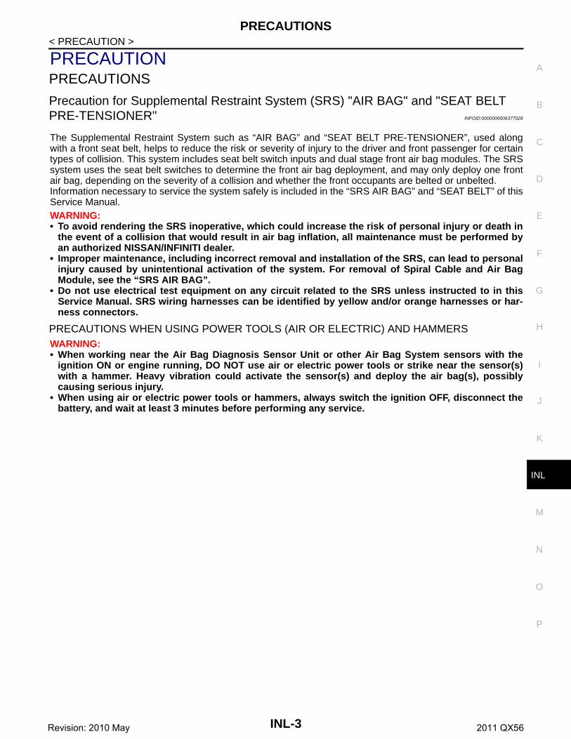
PRECAUTIONPRECAUTIONS
Precaution for Supplemental Restraint System (SRS) "AIR BAG" and "SEAT BELT PRE-TENSIONER" INFOID:0000000006377028
The Supplemental Restraint System such as “AIR BAG” and “SEAT BELT PRE-TENSIONER”, used alongwith a front seat belt, helps to reduce the risk or severity of injury to the driver and front passenger for certaintypes of collision. This system includes seat belt switch inputs and dual stage front air bag modules. The SRSsystem uses the seat belt switches to determine the front air bag deployment, and may only deploy one frontair bag, depending on the severity of a collision and whether the front occupants are belted or unbelted.Information necessary to service the system safely is included in the “SRS AIR BAG” and “SEAT BELT” of thisService Manual.WARNING:• To avoid rendering the SRS inoperative, which could increase the risk of personal injury or death in
the event of a collision that would result in air bag inflation, all maintenance must be performed byan authorized NISSAN/INFINITI dealer.
• Improper maintenance, including incorrect removal and installation of the SRS, can lead to personalinjury caused by unintentional activation of the system. For removal of Spiral Cable and Air BagModule, see the “SRS AIR BAG”.
• Do not use electrical test equipment on any circuit related to the SRS unless instructed to in thisService Manual. SRS wiring harnesses can be identified by yellow and/or orange harnesses or har-ness connectors.
PRECAUTIONS WHEN USING POWER TOOLS (AIR OR ELECTRIC) AND HAMMERSWARNING:• When working near the Air Bag Diagnosis Sensor Unit or other Air Bag System sensors with the
ignition ON or engine running, DO NOT use air or electric power tools or strike near the sensor(s)with a hammer. Heavy vibration could activate the sensor(s) and deploy the air bag(s), possiblycausing serious injury.
• When using air or electric power tools or hammers, always switch the ignition OFF, disconnect thebattery, and wait at least 3 minutes before performing any service.
INL-3Revision: 2010 May 2011 QX56

COMPONENT PARTS
< SYSTEM DESCRIPTION >SYSTEM DESCRIPTIONCOMPONENT PARTS
Component Parts Location INFOID:0000000006216048
Component Description INFOID:0000000006216049
1. BCMRefer to BCS-4, "BODY CONTROL SYSTEM : Component Parts Loca-tion"
2. Personal lamp 3. Luggage room lamp
4. Remote keyless entry receiverRefer to DLK-11, "DOOR LOCK SYSTEM : Component Parts Location"
5. Back door lock assembly(back door switch)
6. Automatic back door close switch
7. Door request switch 8. Door switch 9. Step lamp
10. Paddle lamp 11. Optical sensor 12. IPDM E/RRefer to PCS-4, "Component Parts Location"
13. Vanity mirror lamp 14. Combination meter 15. Combination switch
16. Front door lock assembly (driver side) (door key cylinder switch, un-lock sensor)
17. Door lock and unlock switch 18. Foot lamp
19. Push-button ignition switch 20. AV control unitRefer to AV-9, "Component Parts Lo-cation"
21. Map lamp
JMLIA0837ZZ
Part Description
BCM Controls the interior lighting system.
IPDM E/RControls the integrated relay according to the request signal from BCM (via CAN com-munication).
Remote keyless entry receiver Refer to DLK-12, "DOOR LOCK SYSTEM : Component Description".
AV control uni Receives the dimmer signal from BCM via CAN communication.
Optical sensor Refer to EXL-7, "EXTERIOR LIGHTING SYSTEM : Component Description".
Unlock sensor Detects door lock condition of driver side door.
INL-4Revision: 2010 May 2011 QX56

COMPONENT PARTS
C
D
E
F
G
H
I
J
K
M
A
B
NL
N
O
P
< SYSTEM DESCRIPTION >
I
Combination switch(Lighting & turn signal switch)
Refer to BCS-7, "COMBINATION SWITCH READING SYSTEM : System Description".
• Door lock and unlock switch• Door request switch• Door key cylinder switch
Inputs the lock/unlock signal to BCM.
• Door switch• Back door switch
Inputs the door switch signal to BCM.
Part Description
INL-5Revision: 2010 May 2011 QX56

SYSTEM
< SYSTEM DESCRIPTION >SYSTEMINTERIOR ROOM LAMP CONTROL SYSTEM
INTERIOR ROOM LAMP CONTROL SYSTEM : System Diagram INFOID:0000000006216050
INTERIOR ROOM LAMP CONTROL SYSTEM : System Description INFOID:0000000006216051
OUTLINE• Interior room lamps* are controlled by interior room lamp timer control function of BCM.
*: Map lamp, foot lamp and personal lamp (when map lamp switch and personal lamp switch are in DOORposition).
• Step lamp is controlled by step lamp control function of BCM.• Luggage room lamp and automatic back door close switch illumination are controlled by luggage room lamp
control function of BCM.• Puddle lamp is controlled by puddle lamp timer control function of BCM.• Push-button ignition switch illumination is controlled by the push-button ignition switch illumination control
function of BCM and combination meter.• Interior room lamps and puddle lamp are illuminated by welcome light function of Intelligent Key system.
Refer to DLK-26, "WELCOME LIGHT FUNCTION : System Description".
INTERIOR ROOM LAMP TIMER CONTROL
JMLIA1188GB
INL-6Revision: 2010 May 2011 QX56

SYSTEM
C
D
E
F
G
H
I
J
K
M
A
B
NL
N
O
P
< SYSTEM DESCRIPTION >
I
Interior Room Lamp Timer Basic Operation
NOTE:A: Sets the interior room lamp gradual brightening and dimming time.B: Gradually brightens from 0% to 100% and gradually dims from 100% to 0% in 1 second.• The interior room lamp turns ON and OFF (gradual brightening and dimming) by the interior room lamp
timer.• BCM judges the vehicle condition with the following items. It activates the interior room timer.- Ignition switch status- Door switch signal (except back door)- Door lock/unlock signal (remote keyless entry receiver, each door request switch, door key cylinder switch,
door lock/unlock switch)NOTE:Each function of interior room lamp timer can be set by CONSULT-III. Refer to INL-14, "INT LAMP : CON-SULT-III Function (BCM - INT LAMP)".
Interior Room Lamp ON Operation• BCM always turns the interior room lamp ON when any door opens excepting back door.• When all doors are closed, and any all door unlock operation is performed or ignition switch is turned OFF,
BCM brightens interior room lamp to 30% brightness and maintains 30% brightness until any door opens.• BCM activates the interior room timer in any of the following conditions to turn the interior room lamp ON for
a period of time.- Any door opens before all doors close excepting back door.- Ignition switch is turned ON → OFF.- Any door unlock signal is detected when all doors close excepting back door with ignition switch OFF. NOTE:The timer restarts if new condition is input during the timer operating time.
Interior Room Lamp OFF OperationBCM stops the timer and turns interior room lamp OFF, when any of the following conditions is satisfied.• The interior room lamp timer operating time is expired with all doors closed excepting back door.• Ignition switch position is other than OFF with all doors close excepting back door.• Any door lock signal is detected with all doors close excepting back door.
LUGGAGE ROOM LAMP CONTROLBCM controls the luggage room lamp and automatic back door close switch illumination (ground-side) to turnON with back door switch ON.• When luggage room lamp switch is turned to the ON position, luggage room lamp turns ON.• When luggage room lamp switch is in the DOOR position and back door is opened, luggage room lamp
turns ON.• When back door is opened, automatic back door close switch illumination turn ON.
STEP LAMP CONTROLBCM controls the step lamp (ground-side) to turn ON with any door switch ON excepting back door.
PUDDLE LAMP TIMER CONTROL
Puddle Lamp Timer Basic Operation• BCM controls the ground to turn the puddle lamp ON.
JMLIA0961GB
INL-7Revision: 2010 May 2011 QX56
SYSTEM
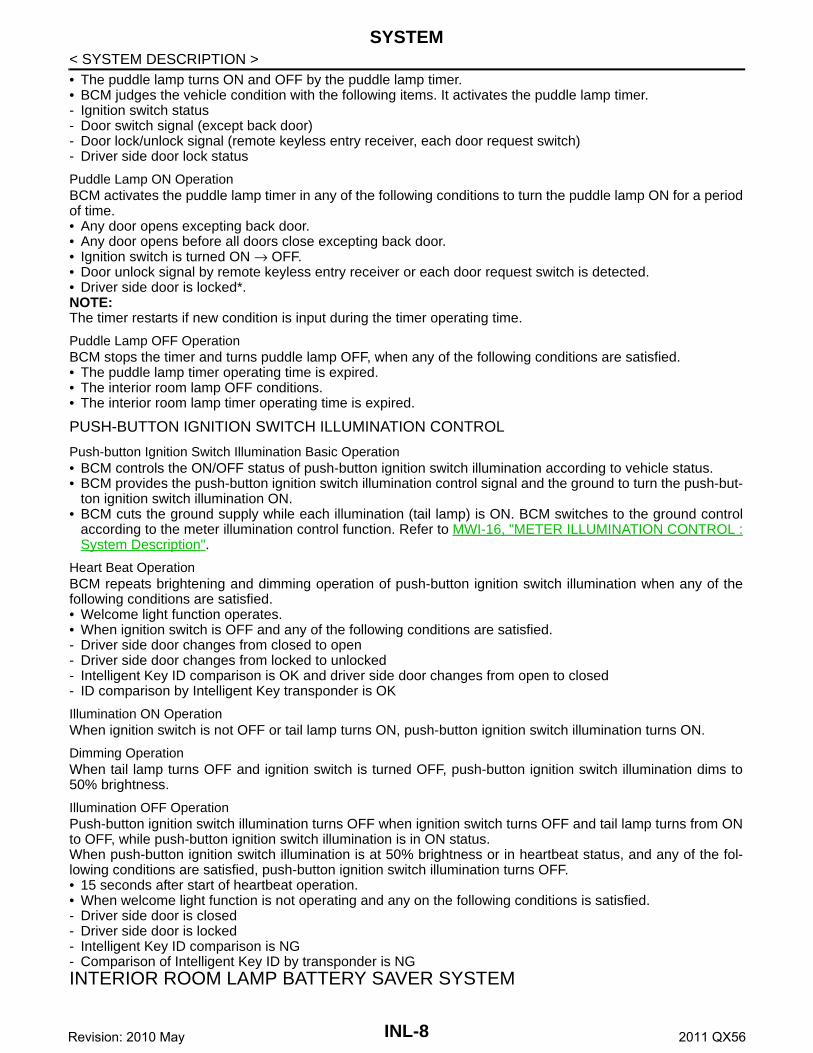
< SYSTEM DESCRIPTION >• The puddle lamp turns ON and OFF by the puddle lamp timer.• BCM judges the vehicle condition with the following items. It activates the puddle lamp timer.- Ignition switch status- Door switch signal (except back door)- Door lock/unlock signal (remote keyless entry receiver, each door request switch)- Driver side door lock statusPuddle Lamp ON OperationBCM activates the puddle lamp timer in any of the following conditions to turn the puddle lamp ON for a periodof time.• Any door opens excepting back door.• Any door opens before all doors close excepting back door.• Ignition switch is turned ON → OFF.• Door unlock signal by remote keyless entry receiver or each door request switch is detected. • Driver side door is locked*. NOTE:The timer restarts if new condition is input during the timer operating time.
Puddle Lamp OFF OperationBCM stops the timer and turns puddle lamp OFF, when any of the following conditions are satisfied.• The puddle lamp timer operating time is expired.• The interior room lamp OFF conditions.• The interior room lamp timer operating time is expired.
PUSH-BUTTON IGNITION SWITCH ILLUMINATION CONTROL
Push-button Ignition Switch Illumination Basic Operation• BCM controls the ON/OFF status of push-button ignition switch illumination according to vehicle status.• BCM provides the push-button ignition switch illumination control signal and the ground to turn the push-but-
ton ignition switch illumination ON.• BCM cuts the ground supply while each illumination (tail lamp) is ON. BCM switches to the ground control
according to the meter illumination control function. Refer to MWI-16, "METER ILLUMINATION CONTROL :System Description".
Heart Beat OperationBCM repeats brightening and dimming operation of push-button ignition switch illumination when any of thefollowing conditions are satisfied.• Welcome light function operates.• When ignition switch is OFF and any of the following conditions are satisfied.- Driver side door changes from closed to open- Driver side door changes from locked to unlocked- Intelligent Key ID comparison is OK and driver side door changes from open to closed- ID comparison by Intelligent Key transponder is OK
Illumination ON OperationWhen ignition switch is not OFF or tail lamp turns ON, push-button ignition switch illumination turns ON.
Dimming OperationWhen tail lamp turns OFF and ignition switch is turned OFF, push-button ignition switch illumination dims to50% brightness.
Illumination OFF OperationPush-button ignition switch illumination turns OFF when ignition switch turns OFF and tail lamp turns from ONto OFF, while push-button ignition switch illumination is in ON status.When push-button ignition switch illumination is at 50% brightness or in heartbeat status, and any of the fol-lowing conditions are satisfied, push-button ignition switch illumination turns OFF.• 15 seconds after start of heartbeat operation.• When welcome light function is not operating and any on the following conditions is satisfied.- Driver side door is closed- Driver side door is locked- Intelligent Key ID comparison is NG- Comparison of Intelligent Key ID by transponder is NGINTERIOR ROOM LAMP BATTERY SAVER SYSTEM
INL-8Revision: 2010 May 2011 QX56
SYSTEM
C
D
E
F
G
H
I
J
K
M
A
B
NL
N
O
P
< SYSTEM DESCRIPTION >
I
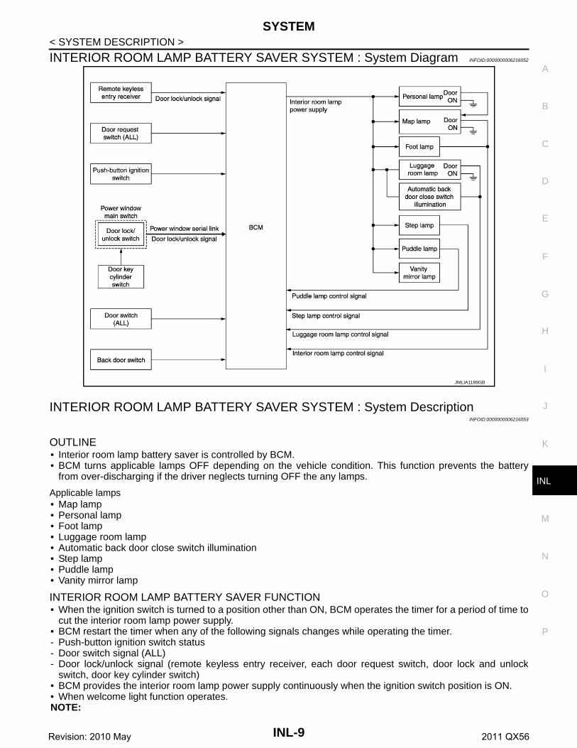
INTERIOR ROOM LAMP BATTERY SAVER SYSTEM : System Diagram INFOID:0000000006216052
INTERIOR ROOM LAMP BATTERY SAVER SYSTEM : System DescriptionINFOID:0000000006216053
OUTLINE• Interior room lamp battery saver is controlled by BCM.• BCM turns applicable lamps OFF depending on the vehicle condition. This function prevents the battery
from over-discharging if the driver neglects turning OFF the any lamps.
Applicable lamps• Map lamp• Personal lamp• Foot lamp• Luggage room lamp• Automatic back door close switch illumination• Step lamp• Puddle lamp• Vanity mirror lamp
INTERIOR ROOM LAMP BATTERY SAVER FUNCTION• When the ignition switch is turned to a position other than ON, BCM operates the timer for a period of time to
cut the interior room lamp power supply.• BCM restart the timer when any of the following signals changes while operating the timer.- Push-button ignition switch status- Door switch signal (ALL)- Door lock/unlock signal (remote keyless entry receiver, each door request switch, door lock and unlock
switch, door key cylinder switch)• BCM provides the interior room lamp power supply continuously when the ignition switch position is ON.• When welcome light function operates.NOTE:
JMLIA1189GB
INL-9Revision: 2010 May 2011 QX56

SYSTEM
< SYSTEM DESCRIPTION >Each function of interior room lamp battery saver can be set by CONSULT-III. Refer to INL-15, "BATTERYSAVER : CONSULT-III Function (BCM - BATTERY SAVER)".ILLUMINATION CONTROL SYSTEMILLUMINATION CONTROL SYSTEM : System Diagram INFOID:0000000006216054
ILLUMINATION CONTROL SYSTEM : System Description INFOID:0000000006216055
OUTLINEEach illumination lamp is controlled by each function of BCM, IPDM E/R and combination meter.
Control by BCM• Combination switch reading function• Headlamp control function
Control by IPDM E/R• Relay control function
Control by combination meter• Meter illumination control function (Refer to MWI-16, "METER ILLUMINATION CONTROL : System Descrip-
tion".)
ILLUMINATION CONTROL• BCM detects the combination switch condition by the combination switch reading function.• BCM transmits position light request signal to IPDM E/R and combination meter according to tail lamp ON
condition.
Tail lamp ON condition- Lighting switch 1ST- Lighting switch 2ND- Lighting switch AUTO, and the auto light function ON judgment- Lighting switch AUTO, with the front fog lamp switch ON and the ignition switch ON• IPDM E/R turns the integrated tail lamp relay ON according to position light request signal. It provides the
power supply to each illumination lamp. • Combination meter enters in the nighttime mode according to position light request signal. Under the night-
time mode the combination meter controls the illuminance by controlling each illumination lamp (groundside).
AUTO LIGHT ADJUSTMENT SYSTEM
JPLIA0855GB
INL-10Revision: 2010 May 2011 QX56

SYSTEM
C
D
E
F
G
H
I
J
K
M
A
B
NL
N
O
P
< SYSTEM DESCRIPTION >
I
AUTO LIGHT ADJUSTMENT SYSTEM : System Diagram INFOID:0000000006216056
AUTO LIGHT ADJUSTMENT SYSTEM : System Description INFOID:0000000006216057
OUTLINE Auto light adjustment system is controlled by each function of BCM, combination meter and AV control unit
Control by BCM• Auto light system• Auto light adjustment system
AUTO LIGHT ADJUSTMENT SYSTEM
Description• BCM supplies voltage to the optical sensor when the ignition switch is turned ON or ACC.• Optical sensor converts outside brightness (lux) to voltage and transmits the optical sensor signal to BCM.• BCM judges dimming/brightening of combination meter and display according to brightness outside the vehi-
cle, when ignition switch is ON.• BCM transmits dimmer signal to combination meter via CAN communication, according to auto light adjust-
ment conditions. Dimmer signal is also transmitted to AV control unit.NOTE:As to dimming/brightening timing, the sensitivity depends on settings. The settings can be changed with CON-SULT-III. Refer to EXL-23, "HEADLAMP : CONSULT-III Function (BCM - HEAD LAMP)".
Auto Light Adjustment Timing TableWhen the ignition switch is ON, the illumination of combination meter and display switches dimming/brighten-ing in the following condition.
BCM switches the illumination of combination meter and display to dimming when outside brighteningobtained from the optical sensor signal is 1250 lx or less for 3 seconds or more. And BCM switches the illumi-nation of combination meter and display to brightening when outside brightening from the optical sensor signalis 2500 lx or more for 5 seconds or more.
JMLIA0967GB
Combination meter and display Dimming/brightening timing
Dimming Outside brightness is 1250 lx or less for 3 seconds or more.
Brightening Outside brightness is 2500 lx or more for 5 seconds or more.
INL-11Revision: 2010 May 2011 QX56

DIAGNOSIS SYSTEM (BCM)
< SYSTEM DESCRIPTION >DIAGNOSIS SYSTEM (BCM)COMMON ITEM
COMMON ITEM : CONSULT-III Function (BCM - COMMON ITEM) INFOID:0000000006368143
APPLICATION ITEMCONSULT-III performs the following functions via CAN communication with BCM.
SYSTEM APPLICATIONBCM can perform the following functions for each system.NOTE:It can perform the diagnosis modes except the following for all sub system selection items.
×: Applicable item
*: This item is indicated, but not used.
FREEZE FRAME DATA (FFD)The BCM records the following vehicle condition at the time a particular DTC is detected, and displays onCONSULT-III.
Diagnosis mode Function Description
Work Support Changes the setting for each system function.
Self Diagnostic Result Displays the diagnosis results judged by BCM. Refer to BCS-57, "DTC Index".
CAN Diag Support MonitorMonitors the reception status of CAN communication viewed from BCM. Refer to CONSULT-III opera-tion manual.
Data Monitor The BCM input/output signals are displayed.
Active Test The signals used to activate each device are forcibly supplied from BCM.
Ecu Identification The BCM part number is displayed.
Configuration• Read and save the vehicle specification.• Write the vehicle specification when replacing BCM.
System Sub system selection itemDiagnosis mode
Work Support Data Monitor Active Test
Door lock DOOR LOCK × × ×
Rear window defogger REAR DEFOGGER × ×
Warning chime BUZZER × ×
Interior room lamp timer INT LAMP × × ×
Exterior lamp HEAD LAMP × × ×
Wiper and washer WIPER × × ×
Turn signal and hazard warning lamps FLASHER × × ×
— AIR CONDITONER* × ×
• Intelligent Key system• Engine start system
INTELLIGENT KEY × × ×
Combination switch COMB SW ×
Body control system BCM ×
IVIS IMMU × × ×
Interior room lamp battery saver BATTERY SAVER × × ×
Back door TRUNK ×
Vehicle security system THEFT ALM × × ×
RAP system RETAINED PWR ×
Signal buffer system SIGNAL BUFFER × ×
INL-12Revision: 2010 May 2011 QX56

DIAGNOSIS SYSTEM (BCM)
C
D
E
F
G
H
I
J
K
M
A
B
NL
N
O
P
< SYSTEM DESCRIPTION >
I
INT LAMP
CONSULT screen item Indication/Unit Description
Vehicle Speed km/h Vehicle speed of the moment a particular DTC is detected
Odo/Trip Meter km Total mileage (Odometer value) of the moment a particular DTC is detected
Vehicle Condition
SLEEP>LOCK
Power position status of the moment a particular DTC is detected
While turning BCM status from low power consumption mode to normal mode (Power supply position is “LOCK”)
SLEEP>OFFWhile turning BCM status from low power consumption mode to normal mode (Power supply position is “OFF”.)
LOCK>ACC While turning power supply position from “LOCK” to “ACC”
ACC>ON While turning power supply position from “ACC” to “IGN”
RUN>ACCWhile turning power supply position from “RUN” to “ACC” (Vehicle is stopping and selector lever is except P position.)
CRANK>RUNWhile turning power supply position from “CRANKING” to “RUN” (From cranking up the engine to run it)
RUN>URGENTWhile turning power supply position from “RUN“ to “ACC” (Emer-gency stop operation)
ACC>OFF While turning power supply position from “ACC” to “OFF”
OFF>LOCK While turning power supply position from “OFF” to “LOCK”
OFF>ACC While turning power supply position from “OFF” to “ACC”
ON>CRANK While turning power supply position from “IGN” to “CRANKING”
OFF>SLEEPWhile turning BCM status from normal mode (Power supply posi-tion is “OFF”.) to low power consumption mode
LOCK>SLEEPWhile turning BCM status from normal mode (Power supply posi-tion is “LOCK”.) to low power consumption mode
LOCKPower supply position is “LOCK” (Ignition switch OFF with steer-ing is locked.)
OFFPower supply position is “OFF” (Ignition switch OFF with steering is unlocked.)
ACC Power supply position is “ACC” (Ignition switch ACC)
ONPower supply position is “IGN” (Ignition switch ON with engine stopped)
ENGINE RUNPower supply position is “RUN” (Ignition switch ON with engine running)
CRANKING Power supply position is “CRANKING” (At engine cranking)
IGN Counter 0 - 39
The number of times that ignition switch is turned ON after DTC is detected• The number is 0 when a malfunction is detected now.• The number increases like 1 → 2 → 3...38 → 39 after returning to the normal condition
whenever ignition switch OFF → ON.• The number is fixed to 39 until the self-diagnosis results are erased if it is over 39.
INL-13Revision: 2010 May 2011 QX56

DIAGNOSIS SYSTEM (BCM)
< SYSTEM DESCRIPTION >INT LAMP : CONSULT-III Function (BCM - INT LAMP) INFOID:0000000006216059
WORK SUPPORT
DATA MONITOR
JMLIA0961GB
Service item Setting item Setting
SET I/L D-UNLCK INTCONOn* With the interior room lamp timer function
Off Without the interior room lamp timer function
ROOM LAMP TIMER SET
MODE 2 7.5 sec.
Sets the interior room lamp ON time. (Timer operating time)MODE 3* 15 sec.
MODE 4 30 sec.
ROOM LAMP ON TIME SET
MODE 1 0.5 sec.
Sets the interior room lamp gradual brightening time.
MODE 2 1 sec.
MODE 3 2 sec.
MODE 4 3 sec.
MODE 5 0 sec.
MODE 6* Gradually brightens from 0% to 100% brightness in 1 second.
ROOM LAMP OFF TIME SET
MODE 1 0.5 sec.
Sets the interior room lamp gradual dimming time.
MODE 2 1 sec.
MODE 3 2 sec.
MODE 4 3 sec.
MODE 5 0 sec.
MODE 6* Gradually dims from 100% to 0% in 1 second.
R LAMP TIMER LOGIC SETMODE 1* Interior room lamp timer activates with synchronizing all doors.
MODE 2 Interior room lamp timer activates with synchronizing the driver door only.
Monitor item[Unit]
Description
REQ SW-DR[On/Off]
The switch status input from door request switch (driver side)
REQ SW-AS[On/Off]
The switch status input from door request switch (passenger side)
REQ SW-RR[On/Off] NOTE:
The item is indicated, but not monitored.REQ SW-RL[On/Off]
INL-14Revision: 2010 May 2011 QX56
DIAGNOSIS SYSTEM (BCM)
C
D
E
F
G
H
I
J
K
M
A
B
NL
N
O
P
< SYSTEM DESCRIPTION >
I
ACTIVE TEST
BATTERY SAVER
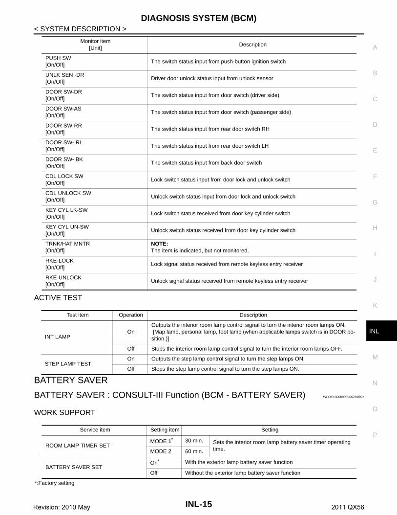
BATTERY SAVER : CONSULT-III Function (BCM - BATTERY SAVER) INFOID:0000000006216060
WORK SUPPORT
*:Factory setting
PUSH SW[On/Off]
The switch status input from push-button ignition switch
UNLK SEN -DR[On/Off]
Driver door unlock status input from unlock sensor
DOOR SW-DR[On/Off]
The switch status input from door switch (driver side)
DOOR SW-AS[On/Off]
The switch status input from door switch (passenger side)
DOOR SW-RR[On/Off]
The switch status input from rear door switch RH
DOOR SW- RL[On/Off]
The switch status input from rear door switch LH
DOOR SW- BK[On/Off]
The switch status input from back door switch
CDL LOCK SW[On/Off]
Lock switch status input from door lock and unlock switch
CDL UNLOCK SW[On/Off]
Unlock switch status input from door lock and unlock switch
KEY CYL LK-SW[On/Off]
Lock switch status received from door key cylinder switch
KEY CYL UN-SW[On/Off]
Unlock switch status received from door key cylinder switch
TRNK/HAT MNTR[On/Off]
NOTE:The item is indicated, but not monitored.
RKE-LOCK[On/Off]
Lock signal status received from remote keyless entry receiver
RKE-UNLOCK[On/Off]
Unlock signal status received from remote keyless entry receiver
Monitor item[Unit]
Description
Test item Operation Description
INT LAMPOn
Outputs the interior room lamp control signal to turn the interior room lamps ON. [Map lamp, personal lamp, foot lamp (when applicable lamps switch is in DOOR po-sition.)]
Off Stops the interior room lamp control signal to turn the interior room lamps OFF.
STEP LAMP TESTOn Outputs the step lamp control signal to turn the step lamps ON.
Off Stops the step lamp control signal to turn the step lamps ON.
Service item Setting item Setting
ROOM LAMP TIMER SETMODE 1* 30 min. Sets the interior room lamp battery saver timer operating
time. MODE 2 60 min.
BATTERY SAVER SETOn* With the exterior lamp battery saver function
Off Without the exterior lamp battery saver function
INL-15Revision: 2010 May 2011 QX56

DIAGNOSIS SYSTEM (BCM)
< SYSTEM DESCRIPTION >DATA MONITOR
ACTIVE TEST
*: Each lamp switch is in ON position.
Monitor item[Unit]
Description
REQ SW-DR[On/Off]
The switch status input from door request switch (driver side)
REQ SW-AS[On/Off]
The switch status input from door request switch (passenger side)
REQ SW-RR[On/Off] NOTE:
The item is indicated, but not monitored.REQ SW-RL[On/Off]
PUSH SW[On/Off]
The switch status input from push-button ignition switch
UNLK SEN-DR[On/Off]
Driver door unlock status input from unlock sensor
DOOR SW-DR[On/Off]
The switch status input from door switch (driver side)
DOOR SW-AS[On/Off]
The switch status input from door switch (passenger side)
DOOR SW-RR[On/Off]
The switch status input from rear door switch RH
DOOR SW- RL[On/Off]
The switch status input from rear door switch LH
DOOR SW- BK[On/Off]
The switch status input from back door switch
CDL LOCK SW[On/Off]
Lock switch status input from door lock and unlock switch
CDL UNLOCK SW[On/Off]
Unlock switch status input from door lock and unlock switch
KEY CYL LK-SW[On/Off]
Lock switch status received from door key cylinder switch
KEY CYL UN-SW[On/Off]
Unlock switch status received from door key cylinder switch
TRNK/HAT MNTR[On/Off]
NOTE:The item is indicated, but not monitored.
RKE-LOCK[On/Off]
Lock signal status received from remote keyless entry receiver
RKE-UNLOCK[On/Off]
Unlock signal status received from remote keyless entry receiver
Test item Operation Description
BATTERY SAVEROff Cuts the interior room lamp power supply to turn interior room lamps OFF.
On Outputs the interior room lamp power supply to turn interior room lamps ON.*
INL-16Revision: 2010 May 2011 QX56

BCM
C
D
E
F
G
H
I
J
K
M
A
B
NL
N
O
P
< ECU DIAGNOSIS INFORMATION >
I
ECU DIAGNOSIS INFORMATIONBCM
List of ECU Reference INFOID:0000000006216061
ECU Reference
BCM
BCS-33, "Reference Value"
BCS-54, "Fail-safe"
BCS-56, "DTC Inspection Priority Chart"
BCS-57, "DTC Index"
INL-17Revision: 2010 May 2011 QX56

INTERIOR ROOM LAMP CONTROL SYSTEM
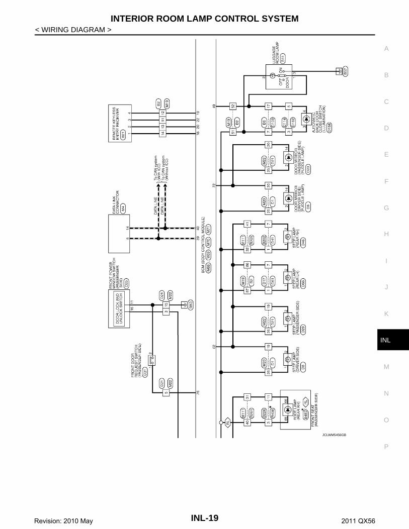
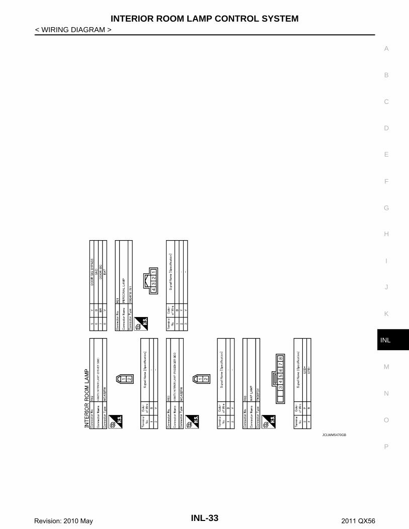
< WIRING DIAGRAM >WIRING DIAGRAMINTERIOR ROOM LAMP CONTROL SYSTEM
Wiring Diagram INFOID:0000000006216062
JCLWM5455GB
INL-18Revision: 2010 May 2011 QX56
INTERIOR ROOM LAMP CONTROL SYSTEM
C
D
E
F
G
H
I
J
K
M
A
B
NL
N
O
P
< WIRING DIAGRAM >
I
JCLWM5456GB
INL-19Revision: 2010 May 2011 QX56

INTERIOR ROOM LAMP CONTROL SYSTEM
< WIRING DIAGRAM >JCLWM5457GB
INL-20Revision: 2010 May 2011 QX56

INTERIOR ROOM LAMP CONTROL SYSTEM
C
D
E
F
G
H
I
J
K
M
A
B
NL
N
O
P
< WIRING DIAGRAM >
I
JCLWM5458GB
INL-21Revision: 2010 May 2011 QX56

INTERIOR ROOM LAMP CONTROL SYSTEM
< WIRING DIAGRAM >JCLWM5459GB
INL-22Revision: 2010 May 2011 QX56

INTERIOR ROOM LAMP CONTROL SYSTEM
C
D
E
F
G
H
I
J
K
M
A
B
NL
N
O
P
< WIRING DIAGRAM >
I
JCLWM5460GB
INL-23Revision: 2010 May 2011 QX56

INTERIOR ROOM LAMP CONTROL SYSTEM
< WIRING DIAGRAM >JCLWM5461GB
INL-24Revision: 2010 May 2011 QX56

INTERIOR ROOM LAMP CONTROL SYSTEM
C
D
E
F
G
H
I
J
K
M
A
B
NL
N
O
P
< WIRING DIAGRAM >
I
JCLWM5462GB
INL-25Revision: 2010 May 2011 QX56

INTERIOR ROOM LAMP CONTROL SYSTEM
< WIRING DIAGRAM >JCLWM5463GB
INL-26Revision: 2010 May 2011 QX56

INTERIOR ROOM LAMP CONTROL SYSTEM
C
D
E
F
G
H
I
J
K
M
A
B
NL
N
O
P
< WIRING DIAGRAM >
I
JCLWM5464GB
INL-27Revision: 2010 May 2011 QX56

INTERIOR ROOM LAMP CONTROL SYSTEM
< WIRING DIAGRAM >JCLWM5465GB
INL-28Revision: 2010 May 2011 QX56

INTERIOR ROOM LAMP CONTROL SYSTEM
C
D
E
F
G
H
I
J
K
M
A
B
NL
N
O
P
< WIRING DIAGRAM >
I
JCLWM5466GB
INL-29Revision: 2010 May 2011 QX56

INTERIOR ROOM LAMP CONTROL SYSTEM
< WIRING DIAGRAM >JCLWM5467GB
INL-30Revision: 2010 May 2011 QX56

INTERIOR ROOM LAMP CONTROL SYSTEM
C
D
E
F
G
H
I
J
K
M
A
B
NL
N
O
P
< WIRING DIAGRAM >
I
JCLWM5468GB
INL-31Revision: 2010 May 2011 QX56

INTERIOR ROOM LAMP CONTROL SYSTEM
< WIRING DIAGRAM >JCLWM5469GB
INL-32Revision: 2010 May 2011 QX56
INTERIOR ROOM LAMP CONTROL SYSTEM
C
D
E
F
G
H
I
J
K
M
A
B
NL
N
O
P
< WIRING DIAGRAM >
I
JCLWM5470GB
INL-33Revision: 2010 May 2011 QX56

ILLUMINATION
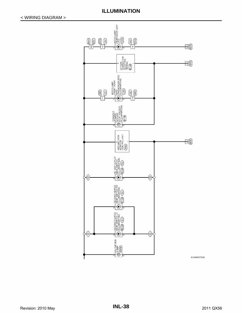
< WIRING DIAGRAM >ILLUMINATION
Wiring Diagram INFOID:0000000006216063
JCLWM5471GB
INL-34Revision: 2010 May 2011 QX56

ILLUMINATION
C
D
E
F
G
H
I
J
K
M
A
B
NL
N
O
P
< WIRING DIAGRAM >
I
JCLWM5472GB
INL-35Revision: 2010 May 2011 QX56

ILLUMINATION
< WIRING DIAGRAM >JCLWM5473GB
INL-36Revision: 2010 May 2011 QX56

ILLUMINATION
C
D
E
F
G
H
I
J
K
M
A
B
NL
N
O
P
< WIRING DIAGRAM >
I
JCLWM5474GB
INL-37Revision: 2010 May 2011 QX56
ILLUMINATION
< WIRING DIAGRAM >JCLWM5475GB
INL-38Revision: 2010 May 2011 QX56

ILLUMINATION
C
D
E
F
G
H
I
J
K
M
A
B
NL
N
O
P
< WIRING DIAGRAM >
I
JCLWM5476GB
INL-39Revision: 2010 May 2011 QX56

ILLUMINATION
< WIRING DIAGRAM >JCLWM5477GB
INL-40Revision: 2010 May 2011 QX56

ILLUMINATION
C
D
E
F
G
H
I
J
K
M
A
B
NL
N
O
P
< WIRING DIAGRAM >
I
JCLWM5478GB
INL-41Revision: 2010 May 2011 QX56

ILLUMINATION
< WIRING DIAGRAM >JCLWM5479GB
INL-42Revision: 2010 May 2011 QX56

ILLUMINATION
C
D
E
F
G
H
I
J
K
M
A
B
NL
N
O
P
< WIRING DIAGRAM >
I
JCLWM5480GB
INL-43Revision: 2010 May 2011 QX56

ILLUMINATION
< WIRING DIAGRAM >JCLWM5481GB
INL-44Revision: 2010 May 2011 QX56

ILLUMINATION
C
D
E
F
G
H
I
J
K
M
A
B
NL
N
O
P
< WIRING DIAGRAM >
I
JCLWM5482GB
INL-45Revision: 2010 May 2011 QX56

ILLUMINATION
< WIRING DIAGRAM >JCLWM5483GB
INL-46Revision: 2010 May 2011 QX56

ILLUMINATION
C
D
E
F
G
H
I
J
K
M
A
B
NL
N
O
P
< WIRING DIAGRAM >
I
JCLWM5484GB
INL-47Revision: 2010 May 2011 QX56

ILLUMINATION
< WIRING DIAGRAM >JCLWM5485GB
INL-48Revision: 2010 May 2011 QX56

ILLUMINATION
C
D
E
F
G
H
I
J
K
M
A
B
NL
N
O
P
< WIRING DIAGRAM >
I
JCLWM5486GB
INL-49Revision: 2010 May 2011 QX56

ILLUMINATION
< WIRING DIAGRAM >JCLWM5487GB
INL-50Revision: 2010 May 2011 QX56

ILLUMINATION
C
D
E
F
G
H
I
J
K
M
A
B
NL
N
O
P
< WIRING DIAGRAM >
I
JCLWM5488GB
INL-51Revision: 2010 May 2011 QX56

ILLUMINATION
< WIRING DIAGRAM >JCLWM5489GB
INL-52Revision: 2010 May 2011 QX56

ILLUMINATION
C
D
E
F
G
H
I
J
K
M
A
B
NL
N
O
P
< WIRING DIAGRAM >
I
JCLWM5490GB
INL-53Revision: 2010 May 2011 QX56
DIAGNOSIS AND REPAIR WORKFLOW
< BASIC INSPECTION >BASIC INSPECTIONDIAGNOSIS AND REPAIR WORKFLOW
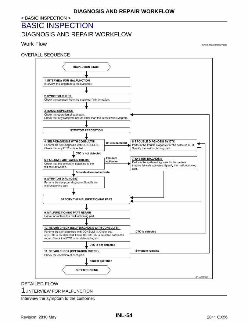
Work Flow INFOID:0000000006216064
OVERALL SEQUENCE
DETAILED FLOW
1.INTERVIEW FOR MALFUNCTION
Interview the symptom to the customer.
JPLIA0313GB
INL-54Revision: 2010 May 2011 QX56

DIAGNOSIS AND REPAIR WORKFLOW
C
D
E
F
G
H
I
J
K
M
A
B
NL
N
O
P
< BASIC INSPECTION >
I
>> GO TO 2.
2.SYMPTOM CHECK
Check the symptom from the customer's information.
>> GO TO 3.
3.BASIC INSPECTION
Check the operation of each part. Check that any symptom occurs other than the interviewed symptom.
>> GO TO 4.
4.SELF-DIAGNOSIS WITH CONSULT-III
Perform the self-diagnosis with CONSULT-III. Check that any DTC is detected.Is any DTC detected?YES >> GO TO 5.NO >> GO TO 6.
5.TROUBLE DIAGNOSIS BY DTC
Perform the trouble diagnosis for the detected DTC. Specify the malfunctioning part.
>> GO TO 9.
6.FAIL-SAFE ACTIVATION CHECK
Check that the symptom is applied to the fail-safe activation.Does the fail-safe activate?YES >> GO TO 7.NO >> GO TO 8.
7.SYSTEM DIAGNOSIS
Perform the system diagnosis for the system that the fail-safe activates. Specify the malfunctioning part.
>> GO TO 9.
8.SYMPTOM DIAGNOSIS
Perform the symptom diagnosis. Specify the malfunctioning part.
>> GO TO 9.
9.MALFUNCTION PART REPAIR
Repair or replace the malfunctioning part.
>> GO TO 10.
10.REPAIR CHECK (SELF-DIAGNOSIS WITH CONSULT-III)
Perform the self-diagnosis with CONSULT-III. Check that any DTC is not detected. Erase DTC if DTC isdetected before the repair. Check that DTC is not detected again.Is any DTC detected?YES >> GO TO 5.NO >> GO TO 11.
11.REPAIR CHECK (OPERATION CHECK)
Check the operation of each part.Does it operate normally?YES >> INSPECTION ENDNO >> GO TO 3.
INL-55Revision: 2010 May 2011 QX56

INTERIOR ROOM LAMP POWER SUPPLY CIRCUIT
< DTC/CIRCUIT DIAGNOSIS >DTC/CIRCUIT DIAGNOSISINTERIOR ROOM LAMP POWER SUPPLY CIRCUIT
Description INFOID:0000000006216065
Provides the interior room lamp power supply. Also cuts the power supply when the interior room lamp batterysaver activating.
Component Function Check INFOID:0000000006216066
1.CHECK INTERIOR ROOM LAMP POWER SUPPLY FUNCTION
CONSULT-III ACTIVE TEST1. Turn ignition switch ON.2. Turn each interior room lamp ON.- Personal lamp- Map lamp- Foot lamp- Luggage room lamp- Automatic back door close switch illumination- Step lamp- Puddle lamp- Vanity mirror lamp3. Select “BATTERY SAVER” of BCM (BATTERY SAVER) active test item.4. With operating the test items, check that each interior room lamp turns ON/OFF.
Does the interior room lamp turn ON/OFF?YES >> Interior room lamp power supply circuit is normal.NO >> Refer to INL-56, "Diagnosis Procedure".
Diagnosis Procedure INFOID:0000000006216067
1.CHECK INTERIOR ROOM LAMP POWER SUPPLY OUTPUT
CONSULT-III ACTIVE TEST1. Turn ignition switch OFF.2. Disconnect the following connectors.- Personal lamp- Map lamp- Foot lamp (both sides)- Luggage room lamp- Automatic back door close switch illumination- Step lamp (ALL)- Puddle lamp (both sides)- Vanity mirror lamp (both sides)3. Turn ignition switch ON.4. Select “BATTERY SAVER” of BCM (BATTERY SAVER) active test item.5. With operating the test item, check voltage between BCM harness connector and ground.
Is the inspection result normal?
Off : Interior room lamp OFFOn : Interior room lamp ON
BCM
(–) Test itemVoltage
(Approx.)(+)
Connector Terminal
M70 56 Ground BATTERY SAVEROff 0 V
On 12 V
INL-56Revision: 2010 May 2011 QX56

INTERIOR ROOM LAMP POWER SUPPLY CIRCUIT
C
D
E
F
G
H
I
J
K
M
A
B
NL
N
O
P
< DTC/CIRCUIT DIAGNOSIS >
I
YES >> GO TO 2.NO >> GO TO 3.
2.CHECK INTERIOR ROOM LAMP POWER SUPPLY OPEN CIRCUIT
1. Turn ignition switch OFF.2. Disconnect the BCM connector.3. Check continuity between BCM harness connector and each interior room lamp harness connector.
Is the inspection result normal?YES >> Check for internal short circuit of each interior room lamp.NO >> Repair or replace harnesses.
3.CHECK INTERIOR ROOM LAMP POWER SUPPLY SHORT CIRCUIT
1. Turn ignition switch OFF.2. Disconnect the BCM connector.3. Check continuity between BCM harness connector and ground.
Is the inspection result normal?YES >> Replace BCM. Refer to BCS-81, "Removal and Installation".NO >> Repair or replace harnesses.
BCM Each interior room lampContinuity
Connector Terminal Connector Terminal
M70 56
Personal lamp R21 3
Existed
Map lamp R18 8
Foot lamp(driver side)
M89 1
Foot lamp(passenger side)
M90 2
Luggage room lamp B11 2
Automatic back door close switch D158 3
Step lamp(driver side)
D8 1
Step lamp(passenger side)
D29 1
Step lamp(Rear LH)
D66 1
Step lamp(Rear RH)
D46 1
Puddle lamp(driver side)
D3 2
Puddle lamp(passenger side)
D23 2
Vanity mirror lamp (driver side) R12 2
Vanity mirror lamp (passenger side)
R13 2
Foot lamp(Rear LH)
B479 65
Foot lamp(Rear RH)
B480 65
BCM
GroundContinuity
Connector Terminal
M70 56 Not existed
INL-57Revision: 2010 May 2011 QX56

INTERIOR ROOM LAMP CONTROL CIRCUIT
< DTC/CIRCUIT DIAGNOSIS >INTERIOR ROOM LAMP CONTROL CIRCUIT
Description INFOID:0000000006216068
Controls each interior room lamp (ground side) by PWM signal.NOTE:PWM signal control period is approximately 250 Hz (in the gradual brightening/dimming).
Component Function Check INFOID:0000000006216069
CAUTION: Before performing the diagnosis, check that the following are normal.• Interior room lamp power supply• Map lamp bulb• Personal lamp bulb• Foot lamp bulb
1.CHECK INTERIOR ROOM LAMP CONTROL FUNCTION
CONSULT-III ACTIVE TEST1. Switch the map lamp switch and personal lamp switch to DOOR.2. Turn ignition switch ON.3. Select “INT LAMP” of BCM (INT LAMP) active test item.4. With operating the test items, check that each interior room lamp turns ON/OFF (gradual brightening/dim-
ming).
Does the interior room lamp turns ON/OFF (gradual brightening/dimming)?YES >> Interior room lamp control circuit is normal.NO >> Refer to INL-58, "Diagnosis Procedure".
Diagnosis Procedure INFOID:0000000006216070
1.CHECK INTERIOR ROOM LAMP CONTROL OUTPUT
CONSULT-III ACTIVE TEST1. Switch the map lamp switch and personal lamp switch to DOOR.2. Turn ignition switch OFF.3. Remove all the bulbs of map lamp, foot lamp and personal lamp.4. Turn ignition switch ON.5. Select “INT LAMP” of BCM (INT LAMP) active test item.6. With operating the test item, check continuity between BCM harness connector and ground.
Is the inspection result normal?YES >> GO TO 2.Fixed ON>>GO TO 3.Fixed OFF>>Replace BCM. Refer to BCS-81, "Removal and Installation".
2.CHECK INTERIOR ROOM LAMP CONTROL OPEN CIRCUIT
1. Turn ignition switch OFF.2. Disconnect BCM connector, map lamp connector, personal lamp connector and foot lamp connector.3. Check continuity between BCM harness connector and foot lamp harness connector.
On : Interior room lamp gradual brighteningOff : Interior room lamp gradual dimming
BCM
Ground
Test item ContinuityConnector Terminal
M70 63 INT LAMPOn Existed
Off Not existed
INL-58Revision: 2010 May 2011 QX56

INTERIOR ROOM LAMP CONTROL CIRCUIT
C
D
E
F
G
H
I
J
K
M
A
B
NL
N
O
P
< DTC/CIRCUIT DIAGNOSIS >
I
4. Check continuity between BCM harness connector and map lamp harness connector.
5. Check continuity between personal lamp harness connector and map lamp harness connector.
Is the inspection result normal?YES >> Replace map lamp, personal lamp or foot lamp.NO >> Repair or replace harnesses.
3.CHECK INTERIOR ROOM LAMP CONTROL SHORT CIRCUIT
1. Turn ignition switch OFF.2. Disconnect BCM connector, map lamp connector, personal lamp connector and foot lamp connector.3. Check continuity between BCM harness connector and ground.
4. Check continuity between personal lamp harness connector and ground.
Is the inspection result normal?YES >> Replace BCM. Refer to BCS-81, "Removal and Installation".NO >> Repair or replace harnesses.
BCM Foot lampContinuity
Connector Terminal Connector Terminal
M70 63
Driver side M89 2
ExistedPassenger side M90 1
Rear LH B47966
Rear RH B480
BCM Map lampContinuity
Connector Terminal Connector Terminal
M70 63 R18 7 Existed
Personal lamp Map lampContinuity
Connector Terminal Connector Terminal
R21 2 R18 5 Existed
BCM
GroundContinuity
Connector Terminal
M70 63 Not existed
Personal lamp
GroundContinuity
Connector Terminal
R21 2 Not existed
INL-59Revision: 2010 May 2011 QX56

LUGGAGE ROOM LAMP CIRCUIT
< DTC/CIRCUIT DIAGNOSIS >LUGGAGE ROOM LAMP CIRCUIT
Description INFOID:0000000006216071
Controls the luggage room lamp and automatic back door close switch illumination (ground side) to turn theluggage room lamp and automatic back door close switch illumination ON and OFF.
Diagnosis Procedure INFOID:0000000006216072
CAUTION: Before performing the diagnosis, check that the following are normal.• Interior room lamp power supply• Luggage room lamp bulb
1.CHECK LUGGAGE ROOM LAMP OUTPUT
1. Turn ignition switch OFF.2. Remove the luggage room bulb.3. Disconnect automatic back door close switch connector.4. Check continuity between BCM harness connector and ground.
Is the inspection result normal?YES >> GO TO 2.Fixed ON>>GO TO 3.Fixed OFF>>Replace BCM. Refer to BCS-81, "Removal and Installation".
2.CHECK LUGGAGE ROOM LAMP OPEN CIRCUIT
1. Disconnect BCM connector.2. Check continuity between BCM harness connector and luggage room lamp harness connector.
3. Check continuity between BCM harness connector and automatic back door close switch harness con-nector.
Is the inspection result normal?YES >> Replace luggage room lamp or automatic back door close switch.NO >> Repair or replace harnesses.
3.CHECK LUGGAGE ROOM LAMP SHORT CIRCUIT
1. Disconnect BCM connector.2. Check continuity between BCM harness connector and ground.
Is the inspection result normal?YES >> Replace BCM. Refer to BCS-81, "Removal and Installation".
BCM
Ground
Condition ContinuityConnector Terminal
M69 49 Back doorOpen Existed
Closed Not existed
BCM Luggage room lampContinuity
Connector Terminal Connector Terminal
M69 49 B11 1 Existed
BCM Automatic back door close switchContinuity
Connector Terminal Connector Terminal
M69 49 D158 4 Existed
BCM
GroundContinuity
Connector Terminal
M69 49 Not existed
INL-60Revision: 2010 May 2011 QX56
LUGGAGE ROOM LAMP CIRCUIT
C
D
E
F
G
H
I
J
K
M
A
B
NL
N
O
P
< DTC/CIRCUIT DIAGNOSIS >
I
NO >> Repair or replace harnesses.
INL-61Revision: 2010 May 2011 QX56

STEP LAMP CIRCUIT
< DTC/CIRCUIT DIAGNOSIS >STEP LAMP CIRCUIT
Description INFOID:0000000006216073
Controls the step lamp (ground side) to turn the step lamp ON and OFF.
Component Function Check INFOID:0000000006216074
CAUTION: Before performing the diagnosis, check that the following is normal.• Interior room lamp power supply• Step lamp bulb
1.CHECK STEP LAMP OPERATION
CONSULT-III ACTIVE TEST1. Turn ignition switch ON.2. Select “STEP LAMP TEST” of BCM (INT LAMP) active test item.3. With operating the test items, check that step lamp turns ON/OFF.
Does the step lamp turn ON/OFF?YES >> Step lamp circuit is normal.NO >> Refer to INL-62, "Diagnosis Procedure".
Diagnosis Procedure INFOID:0000000006216075
1.CHECK STEP LAMP OUTPUT
CONSULT-III ACTIVE TEST1. Turn ignition switch OFF.2. Remove the step lamp bulbs (ALL).3. Turn ignition switch ON.4. Select “STEP LAMP TEST” of BCM (INT LAMP) active test item.5. With operating the test item, check continuity between BCM harness connector and ground.
Is the inspection result normal?YES >> GO TO 2.Fixed ON>>GO TO 3.Fixed OFF>>Replace BCM. Refer to BCS-81, "Removal and Installation".
2.CHECK STEP LAMP OPEN CIRCUIT
1. Turn ignition switch OFF.2. Disconnect BCM connector, and step lamp connector.3. Check continuity between BCM harness connector and step lamp harness connector.
On : Step lamp ONOff : Step lamp OFF
BCM
Ground
Test item ContinuityConnector Terminal
M70 62 STEP LAMP TESTOn Existed
Off Not existed
BCM Step lampContinuity
Connector Terminal Connector Terminal
M70 62
Driver side D8
2 ExistedPassenger side D29
Rear LH D66
Rear RH D46
INL-62Revision: 2010 May 2011 QX56

STEP LAMP CIRCUIT
C
D
E
F
G
H
I
J
K
M
A
B
NL
N
O
P
< DTC/CIRCUIT DIAGNOSIS >
I
Is the inspection result normal?YES >> Replace step lamp.NO >> Repair or replace harnesses.
3.CHECK STEP LAMP SHORT CIRCUIT
1. Turn ignition switch OFF.2. Check continuity between BCM harness connector and ground.
Is the inspection result normal?YES >> Repair or replace harnesses.NO >> Replace BCM. Refer to BCS-81, "Removal and Installation".
BCM
GroundContinuity
Connector Terminal
M70 62 Not existed
INL-63Revision: 2010 May 2011 QX56
PUDDLE LAMP CIRCUIT
< DTC/CIRCUIT DIAGNOSIS >PUDDLE LAMP CIRCUIT
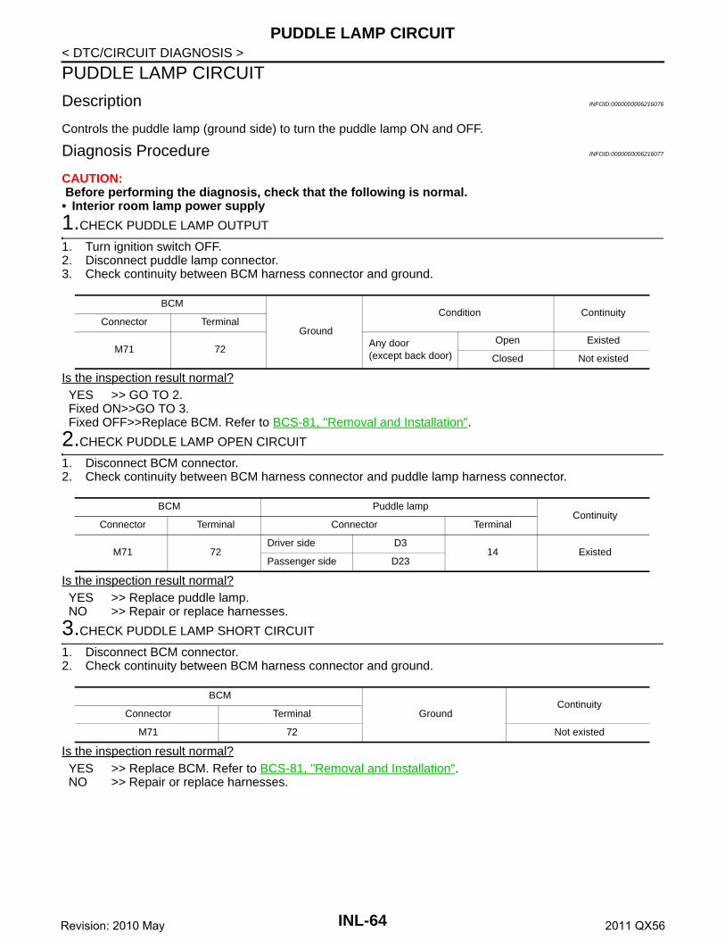
Description INFOID:0000000006216076
Controls the puddle lamp (ground side) to turn the puddle lamp ON and OFF.
Diagnosis Procedure INFOID:0000000006216077
CAUTION: Before performing the diagnosis, check that the following is normal.• Interior room lamp power supply
1.CHECK PUDDLE LAMP OUTPUT
1. Turn ignition switch OFF.2. Disconnect puddle lamp connector.3. Check continuity between BCM harness connector and ground.
Is the inspection result normal?YES >> GO TO 2.Fixed ON>>GO TO 3.Fixed OFF>>Replace BCM. Refer to BCS-81, "Removal and Installation".
2.CHECK PUDDLE LAMP OPEN CIRCUIT
1. Disconnect BCM connector.2. Check continuity between BCM harness connector and puddle lamp harness connector.
Is the inspection result normal?YES >> Replace puddle lamp.NO >> Repair or replace harnesses.
3.CHECK PUDDLE LAMP SHORT CIRCUIT
1. Disconnect BCM connector.2. Check continuity between BCM harness connector and ground.
Is the inspection result normal?YES >> Replace BCM. Refer to BCS-81, "Removal and Installation".NO >> Repair or replace harnesses.
BCM
Ground
Condition ContinuityConnector Terminal
M71 72Any door(except back door)
Open Existed
Closed Not existed
BCM Puddle lampContinuity
Connector Terminal Connector Terminal
M71 72Driver side D3
14 ExistedPassenger side D23
BCM
GroundContinuity
Connector Terminal
M71 72 Not existed
INL-64Revision: 2010 May 2011 QX56

PUSH-BUTTON IGNITION SWITCH ILLUMINATION CIRCUIT
C
D
E
F
G
H
I
J
K
M
A
B
NL
N
O
P
< DTC/CIRCUIT DIAGNOSIS >
I
PUSH-BUTTON IGNITION SWITCH ILLUMINATION CIRCUIT
Component Function Check INFOID:0000000006265016
1.CHECK PUSH-BUTTON IGNITION SWITCH ILLUMINATION OPERATION
CONSULT-III ACTIVE TEST1. Turn the ignition switch ON.2. Select “ENGINE SW ILLUMI” of BCM (INTELLIGENT KEY) active test item.3. With operating the test items, check that the push-button ignition switch illumination turns ON/OFF.
Does the push-button ignition switch illumination turn ON/OFF?YES >> Push-button ignition switch illumination circuit is normal.NO >> Refer to INL-65, "Diagnosis Procedure".
Diagnosis Procedure INFOID:0000000006265017
1.CHECK PUSH-BUTTON IGNITION SWITCH ILLUMINATION POWER SUPPLY OUTPUT
1. Turn ignition switch OFF.2. Lighting switch OFF.3. Disconnect push-button ignition switch connector.4. Check voltage between push-button ignition switch harness connector and ground.
Is the inspection result normal?YES >> GO TO 4.NO >> GO TO 2.
2.CHECK PUSH-BUTTON IGNITION SWITCH ILLUMINATION POWER SUPPLY OPEN CIRCUIT
1. Turn the ignition switch OFF.2. Disconnect BCM connector.3. Check continuity between BCM harness connector and the push-button ignition switch harness connector.
Is the inspection result normal?YES >> GO TO 3.NO >> Repair or replace harnesses.
3.CHECK PUSH-BUTTON IGNITION SWITCH ILLUMINATION POWER SUPPLY SHORT CIRCUIT
Check continuity between BCM harness connector and ground.
Is the inspection result normal?YES >> Replace BCM. Refer to BCS-81, "Removal and Installation".
On : Push-button ignition switch illumination ONOff : Push-button ignition switch illumination OFF
(+)
(–) ConditionVoltage
(Approx.)Push-button ignition switch
Connector Terminal
M101 3 GroundPush-button ignition switch illumination
ON Condition 12 V
OFF Condition 0 V
BCM Push-button ignition switchContinuity
Connector Terminal Connector Terminal
M71 90 M101 3 Existed
BCM
GroundContinuity
Connector Terminal
M71 90 Not existed
INL-65Revision: 2010 May 2011 QX56

PUSH-BUTTON IGNITION SWITCH ILLUMINATION CIRCUIT
< DTC/CIRCUIT DIAGNOSIS >NO >> Repair or replace harnesses.4.CHECK PUSH-BUTTON IGNITION SWITCH ILLUMINATION GROUND CIRCUIT-1
1. Connect push-button ignition switch connector.2. Check voltage between BCM harness connector and ground.
Is the inspection result normal?YES >> GO TO 5.NO >> Replace BCM. Refer to BCS-81, "Removal and Installation".
5.CHECK PUSH-BUTTON IGNITION SWITCH ILLUMINATION GROUND CIRCUIT-2
1. Check continuity between push-button ignition switch harness connector and BCM harness connector.
2. Check continuity between push-button ignition switch harness connector and ground.
Is the inspection result normal?YES >> Replace push-button ignition switch.NO >> Repair or replace harnesses.
(+)
(–) ConditionVoltage
(Approx.)BCM
Connector Terminal
M71 92 GroundPush-button ignition switch illumination
ON Condition 0 V
Push-button ignition switch BCMContinuity
Connector Terminal Connector Terminal
M101 2 M71 92 Existed
Push-button ignition switch
GroundContinuity
Connector Terminal
M101 2 Not existed
INL-66Revision: 2010 May 2011 QX56

INTERIOR LIGHTING SYSTEM SYMPTOMS
C
D
E
F
G
H
I
J
K
M
A
B
NL
N
O
P
< SYMPTOM DIAGNOSIS >
I
SYMPTOM DIAGNOSISINTERIOR LIGHTING SYSTEM SYMPTOMS
Symptom Table INFOID:0000000006216080
CAUTION:Perform the self-diagnosis with CONSULT-III before the symptom diagnosis. Perform the trouble diag-nosis if any DTC is detected.
Symptom Possible cause Inspection item
All the following lamps do not turn ON.• Map lamp• Personal lamp• Vanity mirror lamp• Foot lamp• Step lamp• Puddle lamp • Luggage room lamp• Automatic back door close switch illumination
• Harness between BCM and each interior room lamp
• BCM
Interior room lamp power supply cir-cuitRefer to INL-56, "Component Func-tion Check".
• Interior room lamp does not turn ON even though the door is open.(It turns ON when turning the interior room lamp ON.)
• Interior room lamp does not turn OFF even though the door is closed.
• Harness between BCM and each door switch
• Harness between BCM and each interior room lamp
• BCM
Door switch circuitRefer to DLK-117, "Component Function Check".
Interior room lamp control circuitRefer to INL-58, "Component Func-tion Check".
Interior room lamp timer does not activate.(It turns ON/ OFF when the door opens/closes.)
—Check the interior room lamp setting.Refer to INL-14.
• Puddle lamp does not turn ON even though the door is open.
• Puddle lamp does not turn OFF even though the door is closed.
• Harness between BCM and each door switch
• Harness between BCM and puddle lamp
• BCM
Door switch circuitRefer to DLK-117, "Component Function Check".
Puddle lamp circuitRefer to INL-64, "Diagnosis Proce-dure".
• Luggage room lamp or automatic back door close switch illumination does not turn ON even though the back door is open.(It turns ON when turning the luggage room lamp ON.)
• Luggage room lamp or automatic back door close switch illumination does not turn OFF even though the back door is closed.
• Harness between BCM and back door switch
• Harness between BCM and lug-gage room lamp
• Harness between BCM and auto-matic back door close switch
• BCM
Back door switch circuitRefer to DLK-120, "Component Function Check".
Luggage room lamp circuitRefer to INL-60, "Diagnosis Proce-dure".
• Step lamps (ALL) do not turn ON.• Step lamps (ALL) do not turn OFF.
• Harness between BCM and each step lamp
• BCM
Door switch circuitRefer to DLK-117, "Component Function Check".
Step lamp circuitRefer to INL-62.
Push-button ignition switch illumination does not illuminate.
• Harness between BCM and push-button ignition switch
• BCM
Push-button ignition switch illumina-tion circuitRefer to INL-65, "Component Func-tion Check".
Interior room lamp battery saver does not acti-vate.
BCMReplace BCM.Refer to BCS-81, "Removal and In-stallation".
INL-67Revision: 2010 May 2011 QX56
MAP LAMP
< REMOVAL AND INSTALLATION >REMOVAL AND INSTALLATIONMAP LAMP
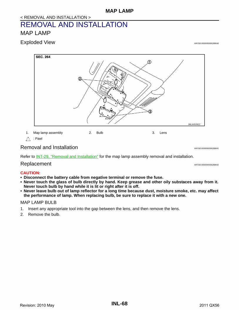
Exploded View INFOID:0000000006288640
Removal and Installation INFOID:0000000006288641
Refer to INT-29, "Removal and Installation" for the map lamp assembly removal and installation.
Replacement INFOID:0000000006288642
CAUTION:• Disconnect the battery cable from negative terminal or remove the fuse.• Never touch the glass of bulb directly by hand. Keep grease and other oily substaces away from it.
Never touch bulb by hand while it is lit or right after it is off.• Never leave bulb out of lamp reflector for a long time because dust, moisture smoke, etc. may affect
the performance of lamp. When replacing bulb, be sure to replace it with a new one.
MAP LAMP BULB1. Insert any appropriate tool into the gap between the lens, and then remove the lens.2. Remove the bulb.
1. Map lamp assembly 2. Bulb 3. Lens
: Pawl
JMLIA0539ZZ
INL-68Revision: 2010 May 2011 QX56

VANITY MIRROR LAMP
C
D
E
F
G
H
I
J
K
M
A
B
NL
N
O
P
< REMOVAL AND INSTALLATION >
I
VANITY MIRROR LAMP
Exploded View INFOID:0000000006288643
Replacement INFOID:0000000006288644
CAUTION:• Disconnect the battery cable from negative terminal or remove the fuse.• Never touch the glass of bulb directly by hand. Keep grease and other oily substaces away from it.
Never touch bulb by hand while it is lit or right after it is off.• Never leave bulb out of lamp reflector for a long time because dust, moisture smoke, etc. may affect
the performance of lamp. When replacing bulb, be sure to replace it with a new one.
VANITY MIRROR LAMP BULB1. Insert any appropriate tool into the gap between the lens, and then remove the lens.2. Remove the bulb.
1. Lens 2. Bulb
: Pawl
JMLIA1048ZZ
INL-69Revision: 2010 May 2011 QX56

GLOVE BOX LAMP
< REMOVAL AND INSTALLATION >GLOVE BOX LAMP
Exploded View INFOID:0000000006288647
Replacement INFOID:0000000006288648
CAUTION:• Disconnect the battery cable from negative terminal or remove the fuse.• Never touch the glass of bulb directly by hand. Keep grease and other oily substaces away from it.
Never touch bulb by hand while it is lit or right after it is off.• Never leave bulb out of lamp reflector for a long time because dust, moisture smoke, etc. may affect
the performance of lamp. When replacing bulb, be sure to replace it with a new one.
GLOVE BOX LAMP BULB1. Remove glove box assembly. Refer to IP-14, "Removal and Installation".2. Rotate the bulb socket counterclockwise and unlock it.3. Remove the bulb.
1. Glove box assembly 2. Bulb socket 3. Bulb
4. Lamp housing
JMLIA1050ZZ
INL-70Revision: 2010 May 2011 QX56

FOOT LAMP
C
D
E
F
G
H
I
J
K
M
A
B
NL
N
O
P
< REMOVAL AND INSTALLATION >
I
FOOT LAMPDRIVER SIDE
DRIVER SIDE : Exploded View INFOID:0000000006288649
DRIVER SIDE : Replacement INFOID:0000000006288650
CAUTION:• Disconnect the battery cable from negative terminal or remove the fuse.• Never touch the glass of bulb directly by hand. Keep grease and other oily substaces away from it.
Never touch bulb by hand while it is lit or right after it is off.• Never leave bulb out of lamp reflector for a long time because dust, moisture smoke, etc. may affect
the performance of lamp. When replacing bulb, be sure to replace it with a new one.
FOOT LAMP BULB (DRIVER SIDE)1. Remove instrument lower panel LH. Refer to IP-14, "Removal and Installation".2. Rotate the bulb socket counterclockwise and unlock it.3. Remove the bulb.
PASSENGER SIDE
PASSENGER SIDE : Exploded View INFOID:0000000006288651
1. Bulb socket 2. Bulb 3. Lamp housing
4. Instrument lower panel LH
JMLIA1051ZZ
JMLIA1052ZZ
INL-71Revision: 2010 May 2011 QX56

FOOT LAMP
< REMOVAL AND INSTALLATION >PASSENGER SIDE : Replacement INFOID:0000000006288652
CAUTION:• Disconnect the battery cable from negative terminal or remove the fuse.• Never touch the glass of bulb directly by hand. Keep grease and other oily substaces away from it.
Never touch bulb by hand while it is lit or right after it is off.• Never leave bulb out of lamp reflector for a long time because dust, moisture smoke, etc. may affect
the performance of lamp. When replacing bulb, be sure to replace it with a new one.
FOOT LAMP BULB (PASSENGER SIDE)1. Remove instrument lower cover. Refer to IP-14, "Removal and Installation".2. Rotate the bulb socket counterclockwise and unlock it.3. Remove the bulb.
REAR FOOT LAMP
REAR FOOT LAMP : Exploded View INFOID:0000000006288653
REAR FOOT LAMP : Removal and Installation INFOID:0000000006288654
CAUTION:• Disconnect the battery cable from negative terminal or remove the fuse.• Never touch rear foot lamp assembly directly by hand. Keep grease and other oily substaces away
from it.• Never touch rear foot lamp assembly by hand while it is lit or right after it is off.
REMOVAL1. Remove seat cushion front finisher. Refer to SE-112, "Removal and Installation".2. Release seatback lower carpet band from the back of seat cushion frame.3. Pull seatback lower carpet toward vehicle rear from underside.
1. Instrument lower cover 2. Lamp housing 3. Bulb
4. Bulb socket
1. Rear foot lamp assembly 2. Seatback lower carpet
: Clip
: Pawl
Vehicle front
JMLIA1149ZZ
INL-72Revision: 2010 May 2011 QX56

FOOT LAMP
C
D
E
F
G
H
I
J
K
M
A
B
NL
N
O
P
< REMOVAL AND INSTALLATION >
I
4. Disengage rear foot lamp assembly fixing pawls using a smallflat-bladed screwdriver (A) as shown by the arrow in the figure.
5. Remove rear foot lamp assembly from seatback lower carpet.
INSTALLATIONNote the following items, and install in the reverse order of removal.CAUTION:• Rear foot lamp cannot be disassembled.• Always replace rear foot lamp as an assembly, when replacing.
:Pawl
:Vehicle front
JMLIA1150ZZ
INL-73Revision: 2010 May 2011 QX56

STEP LAMP
< REMOVAL AND INSTALLATION >STEP LAMP
Exploded View INFOID:0000000006288655
Removal and Installation INFOID:0000000006288656
CAUTION:• Disconnect the battery cable from negative terminal or remove the fuse.• Never touch the glass of bulb directly by hand. Keep grease and other oily substaces away from it.
Never touch bulb by hand while it is lit or right after it is off.• Never leave bulb out of lamp reflector for a long time because dust, moisture smoke, etc. may affect
the performance of lamp. When replacing bulb, be sure to replace it with a new one.
REMOVAL1. Insert any appropriate tool into the gap between the step lamp and door finisher.2. Disconnect the step lamp harness connector, and then remove the step lamp.
INSTALLATIONInstall in the reverse order of removal.
Replacement INFOID:0000000006288657
STEP LAMP BULB1. Remove the step lamp.2. Remove the lens.3. Remove the bulb.
1. Step lamp housing 2. Bulb 3. Lens
: Pawl
: Metal clip
JMLIA0541ZZ
INL-74Revision: 2010 May 2011 QX56

MOOD LAMP
C
D
E
F
G
H
I
J
K
M
A
B
NL
N
O
P
< REMOVAL AND INSTALLATION >
I
MOOD LAMPFRONT DOOR ARMREST
FRONT DOOR ARMREST : Exploded View INFOID:0000000006288658
FRONT DOOR ARMREST : Replacement INFOID:0000000006288659
CAUTION:• Disconnect the battery cable from negative terminal or remove the fuse.• Never touch the glass of bulb directly by hand. Keep grease and other oily substaces away from it.
Never touch bulb by hand while it is lit or right after it is off.• Never leave bulb out of lamp reflector for a long time because dust, moisture smoke, etc. may affect
the performance of lamp. When replacing bulb, be sure to replace it with a new one.
MOOD LAMP1. Remove front door finisher. Refer to INT-14, "Removal and Installation".2. Remove the mood lamp from front door finisher.
REAR DOOR ARMREST
REAR DOOR ARMREST : Exploded View INFOID:0000000006288660
1. Mood lamp
JMLIA1054ZZ
1. Mood lamp
JMLIA1055ZZ
INL-75Revision: 2010 May 2011 QX56

MOOD LAMP
< REMOVAL AND INSTALLATION >REAR DOOR ARMREST : Replacement INFOID:0000000006288661
CAUTION:• Disconnect the battery cable from negative terminal or remove the fuse.• Never touch the glass of bulb directly by hand. Keep grease and other oily substaces away from it.
Never touch bulb by hand while it is lit or right after it is off.• Never leave bulb out of lamp reflector for a long time because dust, moisture smoke, etc. may affect
the performance of lamp. When replacing bulb, be sure to replace it with a new one.
MOOD LAMP1. Remove rear door finisher. Refer to INT-14, "Removal and Installation".2. Remove the mood lamp from rear door finisher.
INL-76Revision: 2010 May 2011 QX56

PERSONAL LAMP
C
D
E
F
G
H
I
J
K
M
A
B
NL
N
O
P
< REMOVAL AND INSTALLATION >
I
PERSONAL LAMP
Exploded View INFOID:0000000006288662
Removal and Installation INFOID:0000000006288663
CAUTION:• Disconnect the battery cable from negative terminal or remove the fuse.• Never touch the glass of bulb directly by hand. Keep grease and other oily substaces away from it.
Never touch bulb by hand while it is lit or right after it is off.• Never leave bulb out of lamp reflector for a long time because dust, moisture smoke, etc. may affect
the performance of lamp. When replacing bulb, be sure to replace it with a new one.• Replace the personal lamp case as a set (LH and RH). After removing the headlining assembly,
remove the personal lamp case.
REMOVAL1. Remove headlining assembly. Refer to INT-29, "Removal and Installation".
1. Personal lamp case 2. Bulb 3. Lens
4. Personal lamp finisher
: Pawl
JMLIA1053ZZ
INL-77Revision: 2010 May 2011 QX56

PERSONAL LAMP
< REMOVAL AND INSTALLATION >2. Press the pawls (B) on both sides as shown in the figure using asmall flat-bladed screwdriver (A), and then pull out personallamp case (2) from personal lamp finisher (1).
INSTALLATIONInstall in the reverse order of removal.
Replacement INFOID:0000000006288664
CAUTION:• Disconnect the battery negative terminal or remove the fuse.• Never touch the glass of bulb directly by hand. Keep grease and other oily matters away from it.
Never touch bulb by hand while it is lit or right after being turned off.• Never leave bulb out of lamp reflector for a long time because dust, moisture smoke, etc. may affect
the performance of lamp. When replacing bulb, be sure to replace it with new one.
PERSONAL LAMP BULB1. Insert any appropriate tool into the gap between the lens, and then remove the lens.2. Remove the bulb.
JMLIA1058ZZ
INL-78Revision: 2010 May 2011 QX56

PUDDLE LAMP
C
D
E
F
G
H
I
J
K
M
A
B
NL
N
O
P
< REMOVAL AND INSTALLATION >
I
PUDDLE LAMP
Exploded View INFOID:0000000006288665
Removal and Installation INFOID:0000000006288666
CAUTION:• Disconnect the battery cable from negative terminal or remove the fuse.• Never touch puddle lamp directly by hand. Keep grease and other oily substaces away from it. • Never touch puddle lamp by hand while it is lit or right after it is off.• It is prohibited to disassemble puddle lamp.• Always replace puddle lamp as an assembly, when replacing.
REMOVAL1. Remove door mirror assembly. Refer to MIR-32, "DOOR MIRROR ASSEMBLY : Removal and Installa-
tion".2. Disconnect puddle lamp harness connector terminal from door mirror harness connector.3. Disengage base cover fixing pawls using a small flat-bladed
screwdriver (A), and then remove base cover.CAUTION:• Apply protective tape (B) around the base to protect the
surface from damage.• Apply protective tape to small flat-bladed screwdriver.
1. Door mirror assembly 2. Puddle lamp 3. Base cover
: Pawl
JMLIA1148ZZ
: Pawl
JMLIA0922ZZ
INL-79Revision: 2010 May 2011 QX56

PUDDLE LAMP
< REMOVAL AND INSTALLATION >4. Disengage puddle lamp fixing pawls, and then remove puddlelamp (1) from base cover (2).
INSTALLATIONInstall in the reverse order of removal.
: Pawl
JMLIA1283ZZ
INL-80Revision: 2010 May 2011 QX56

LUGGAGE ROOM LAMP
C
D
E
F
G
H
I
J
K
M
A
B
NL
N
O
P
< REMOVAL AND INSTALLATION >
I
LUGGAGE ROOM LAMP
Exploded View INFOID:0000000006288667
Removal and Installation INFOID:0000000006288668
CAUTION:• Disconnect the battery cable from negative terminal or remove the fuse.• Never touch the glass of bulb directly by hand. Keep grease and other oily substaces away from it.
Never touch bulb by hand while it is lit or right after it is off.• Never leave bulb out of lamp reflector for a long time because dust, moisture smoke, etc. may affect
the performance of lamp. When replacing bulb, be sure to replace it with a new one.
REMOVAL1. Insert any appropriate tool into the gap between lens and roof garnish, and then remove lens.2. Disengage luggage room lamp housing fixing metal clips, and then disconnect luggage room lamp har-
ness connector.3. Remove luggage room lamp housing.
INSTALLATIONInstall in the reverse order of removal.
Replacement INFOID:0000000006288669
CAUTION:• Disconnect the battery cable from negative terminal or remove the fuse.• Never touch the glass of bulb directly by hand. Keep grease and other oily substaces away from it.
Never touch bulb by hand while it is lit or right after it is off.• Never leave bulb out of lamp reflector for a long time because dust, moisture smoke, etc. may affect
the performance of lamp. When replacing bulb, be sure to replace it with a new one.
LUGGAGE ROOM LAMP BULB1. Insert any appropriate tool into the gap between lens and roof garnish, and then remove the lens.2. Remove bulb.
1. Lens 2. Bulb 3. Luggage room lamp housing
4. Roof garnish
: Pawl
: Vehicle front
JMLIA1056ZZ
INL-81Revision: 2010 May 2011 QX56

SERVICE DATA AND SPECIFICATIONS (SDS)
< SERVICE DATA AND SPECIFICATIONS (SDS)SERVICE DATA AND SPECIFICATIONS (SDS)SERVICE DATA AND SPECIFICATIONS (SDS)
Bulb Specifications INFOID:0000000006288670
Item Type Wattage (W)
Push-button ignition switch illumination LED —
Map lamp Wedge 8
Console lamp(integrated into the map lamp assembly)
LED —
Puddle lamp LED —
Vanity mirror lamp — 2
Glove box lamp Wedge 1.4
Foot lamp (driver and passenger) Wedge 1.4
Rear foot lamp LED —
Mood lamp (front and rear door armrest) LED —
Step lamp Wedge 8
Personal lamp Wedge 8
Luggage room lamp — 8
INL-82Revision: 2010 May 2011 QX56