Embed Size (px)
Citation preview
Innova
tion
Advance+
NEVER STOP IMPROVING
2012
Data code X 6210048
V1.1
Drive and Control Solutions for Injection Molding Machine
TUV Rheinland Group
ISO9001 Certified
AC Drive | Servo Drive | Integrated Controller | PLC | HMI | PMSM | Energy
Contact Information of Agency
Copyright Shenzhen Inovance Co., Ltd. All Rights Reserved.
Shenzhen lnovance Technology Co., Ltd.Add.: Building E, Hongwei Industry Park, Liuxian Road, Baocheng No. 70 Zone, Bao’an District, ShenzhenTel: +86 755 2979 9595Fax: +86 755 2961 9897Technical Support: 400-777-1260http://www.inovance.cn

01/02
Injection Drive System Revolution
General Products and Solutions
PLC
HMI PC
Integrated andspecial drives
Standard products
ISMH/ISMV ISMG ISMD ISMD
NICE3000 CAN600 MD Series Inverter IS500 IS300 NICE900 IS300 (L)
Injection Drive System Revolution
Service Network
Heilongjiang
Jilin
LiaoningBeijing
Tianjin
Hebei
Shanxi
Shandong
Henan
Anhui
Shannxi
Hubei
Jiangsu
Shanghai
Zhejiang
Fujian
Jiangxi
Shenzhen,GuangdongGuangxi
HunanGuizhou
Yunnan
Sichuan Chongqing
Shenzhen HQ
Suzhou HQ
Headquarter in Shenzhen and Suzhou, with a number of subsidiaries in HK, Hangzhou, etc41 offices throughout ChinaOver 400 sales and service engineers200 authenticated distributors50 nationwide warranty centers8 spare parts centers
Quickly respond to customer needs.
Suzhou: Suzhou Inovance Technology Co., Ltd.
HQ & Branch Network
ABOUT INOVANCE
Shenzhen: Shenzhen Inovance Technology Co., Ltd.
Shenzhen Inovance Technology Co., Ltd. (Stock code: 300124) is a leading industrial automation product and solution provider, dedicated to R&D, manufacturing and sales of automation control products. Targeting at high-end equipment manufacturers, we are committed to achieving a win-win situation with customers based on our solid automation control technologies with IPRs. We have maintained a mature business model through which customized solutions have been constantly and rapidly delivered to customers.
Our offering provides low/mid-voltage AC drives, PLCs, HMIs, servo drives, motors, photoelectric encoders, integrated and special drives, and renewable energy products, etc. We are now taking up the largest market share in domestic low-voltage section and have obtained a leading position in various segmentation markets with our all-round integrated and special drives.
As a national high-tech enterprise, we have obtained 57 authorized patents till the end of year 2011, including 9 invention patents, 31 utility model patents and 17 design patents. Besides, we have mastered various core platform technologies covering the fields of high-performance vector control inverter, PLC, servo, and PMSM. Attracting and cultivating talents is our constant pursuit. Till now, Inovance has already owned a large group of professional R&D experts dedicated to development of core platform technologies, application technologies and new products.
Suzhou Factory

Injection Drive System Revolution
Energy-saving Compared with traditional constant/variable displacement pump systems, the servo pump system combines servo
motor's fast stepless speed regulating and hydraulic pump's self pressure adjusting, bringing tremendous energy
savings which can reach up to 80%.
PC of Injection Molding Machine Servo MotorIS300 Series Servo Drive
100%
90%
80%
70%
60%
50%
40%
30%
20%
10%
0 1 2 3 4 5 6 7 8 9 10 11 12 13 14 15 16 17 18 19 20 21
Accuracy1. Position repetition accuracy:
Fast response guarantees the mold-closed/opening accuracy; accuracy of the end ejection position can reach to 0.1 mm.
An injection accuracy of 0.3% can be achieved with additional accuracy molds.
2. Pressure control accuracy:
Highly accurate and responsive PID module guarantees a stable system pressure which fluctuates within ±0.5 bar, thus
greatly improving the formation quality of plastic products.
1. High efficiency arising from high rotational speed
The pump's output flow can be increased by increasing the motor's rotational speed, thus improving the running speed of
the .
2. Fast response
Response time can be shortened to 20ms, which improves the response time of the hydraulic system.
Under the control of the excellent PID module, the injection molding machine with servo pump system is of much lower noise than a common one. When configured
with a low-noise screw pump, the injection molding machine can reach a noise of below 70dB, which greatly improves the working environment.
entire machine
20ms
Max. Output
Re
sp
on
se C
urv
e
Response time: 20ms
0 20 100 150 0 20 100 150
Response Time
Variable displacement pump system
Servo pump system
Constant displacement pump system
Frames of Traditional Injection Molding Machine System and Servo Pump System
Screw Pump
Gear Pump
Plunger Pump
OR
OR
Servo pump system consumes low power in the pressure holding stage.
Constant displacement pump system Variable displacement pump systemServo pump system
Structure of Servo Pump System
Servo Pump System Solution for Injection Molding Machine Features of Servo Pump System for Injection Molding Machine
03/04
Servo pump system consumes nearly 0 power in the cooling stage.
Constant Displacement Pump System
Variable Displacement Pump System
Servo Pump System
Pressure Sensor
Actuator
Common Asynchronous
Motor
VariableDisplacement
Pump
Actuator
Common Asynchronous
Motor
Constant Displacement
Pump
M~
Control Valve
Control Valve
M~
Actuator
Control Valve
ConstantDisplacement
Pump
Pressure Sensor
PMSMResolver
M ~
Servo Drive
System Reference Pressure and Flow Signals
P V
PG
Mold-closed Injection Pressure Holding Storing Cooling
Mold-opening EjectionP(
Consumption%)Power
High Efficiency
Po
we
r Co
nsu
mp
tion
Noiseless

Injection Drive System Revolution
Manufacturing Examples
Product Automotive interior trim panel
Material PP
Testing Time 24 hours
Project
Energy saving
High Efficiency
750T injection molding machine with servo pump
Average Power Consumption per Hour
Repetition Accuracy (Weight)
Pass Rate
Manufacturing Cycle
17.68kW/h
0.30%
98%
90s
44.48kW/h
1.2%
85%
93s
800T injection molding machine with variable displacement pump
Servo Drive Features
Example 1: Automotive interior trim panel
05/06
Accuracy
Product
Material
Testing Time 24 hours
Project
Energy Saving
High Efficiency
Average Power Consumptionper Hour
Repetition Accuracy (Weight)
Pass Rate
Manufacturing Cycle
Accuracy
Charger case
ABS
130T injection molding machine with servo pump
5.88kW/h
0.28%
99%
23.5s 24.3s
90%
0.88%
8.30kW/h
130T injection molding machine with variable displacement pump
Human-based parameter setting and adjusting
Example 2: Charger case
High-speed bus interaction
High-speed bus interaction
Pressure/Flow instruction
1. Default factory settings with experience parameters, which can meet 80% of field requirements.
2. Multiple options of motor self-tuning modes
3. Binding motor parameters
Convenient pressure ring adjusting
1. Dedicated parameters for adjusting pressure stability
2. Dedicated parameters for adjusting pressure overshoot
3. Dedicated parameters for adjusting pressure rise time
4. Multi-PID control switchover
Distinctive multi-pump converging control
1. Intelligent control — Multi-pump
converging/synchronization can be realized in the same
machine set.
2. Easy communication parameter debugging — User only
needs to define the master and slave pumps.
3. Easy pressure response debugging — User only needs to
adjust the pressure response parameter of the master pump.
4. Linkage alarm — The master pump displays the station
where alarm occurs.
5. Pressure holding control, which can cut off the operations
of the slave pump intelligently.
1. Higher holding pressure under the same configuration
2. More stable pressure control and slighter fluctuation
3. Non-terminable pressure holding
4. Decreasing the temperature rise of the pump, motor and
hydraulic oil;
extending the service life of the entire machine
5. Further decreasing power consumption
1. Specifications of compatible injection molding machine:
2. Specifications of compatible servo motor:
3. Specifications of compatible pump:
50T~4500T.
0.4kW~160kW.
16ml/ rev~280ml/ rev.
Powerful adaptability to various motor models
Servo drive conducts dual-displacement
switchover in specified
conditions.
Distinctive control for dual-displacement plunger pump & dual gear pump
Capacity specifications: Rated output current of a single drive: 2.1A~725A, which equals to a rated power range from 0.4kW
to 400kW .
Complete drive models and capacity range
1. High accountability: Fault rate < 0.5%
2. High margin design, which better adapts to high-intensity operations of injection molding machines.
3. Built-in DC reactor, which effectively guarantees stable operation of the machine.
4. Interfacing perfectly with various types of pressure sensors: User can set the specifications of the pressure sensor.
6. Water cooling drive: realizing the optimal power-to-volume ratio which meets the requirement for fast installation.
7. CE certified, supporting various voltages in different countries. Currently, a number of Inovance servo drives have been
applied in foreign fields.
8. Motor overheat inspection and sensor power short circuit protection: guaranteeing safe running of the injection molding
machine.
5. PCBs are covered with conformal coatings, which enable the drives to work normally in the environment with oil mist,
dust and moisture.
Other features
Large displacement
Small displacement
Pump output pressureMotor output torque/Drive output current

Naming Rules
Injection System Revolution Drive
Capacity Specifications
IS300 Series General-purpose Servo Drive
07/08
⑤
Cooling mode
Blank: Forced air cooling (default)
L: Water cooling
⑤
IS300 T 030 - C - L① ③ ④②
Type of interface board
C: With CAN communication and
PTC sensor (motor overheat
protection)
Note: Standard drive is configured
with a resolver PG card of resolver.
① Series
IS300 series servo drive
②
Voltage level
S: single-phase 220V
2T: 3-phase 220V
T: 3-phase 380V
5T: 3-phase 480V
③ Rated output current (approx)
RemarksPower Supply
Capacity(kVA)
Input Current(A)
Rated Output Current (A)
Recommended Power of Brake Resistance W( )
Recommended Brake
Resistance (Ω) Braking Unit
Built-in
/
Model(kW) (HP)
Adaptable Motor (S1)
IS300S002-C
IS300S003-C
IS300S004-C
IS300S005-C
Three-phase 220V, 50/60Hz
IS300-2T002-C
IS300-2T003-C
IS300-2T004-C
IS300-2T005-C
IS300-2T010-C
IS300-2T020-C
IS300-2T030-C
IS300-2T040-C
IS300-2T050-C
IS300-2T070-C
IS300-2T080-C
IS300-2T100-C
IS300-2T140-C
IS300-2T170-C
IS300-2T210-C
IS300-2T300-C
IS300-2T140-C-L
IS300-2T170-C-L
IS300-2T210-C-L
IS300-2T300-C-L
Single-phase 220V, 50/60Hz
1
1.5
3
4
1.5
3
4
5.9
8.9
17
21
30
40
57
69
85
114
134
160
231
114
134
160
231
5.4
8.2
14
23
3.4
5
5.8
10.5
14.6
26
35
46.5
62
76
92
113
157
180
214
307
157
180
214
307
2.3
4
7
9.6
2.1
3.8
5.1
9
13
25
32
45
60
75
91
112
150
176
210
304
150
176
210
304
0.4
0.75
1.5
2.2
0.4
0.75
1.5
2.2
3.7
5.5
7.5
11
15
18.5
22
30
37
45
55
75
37
45
55
75
0.5
1
2
3
0.5
1
2
3
5
7.5
10
15
20
25
30
40
50
60
75
100
50
60
75
100
80W
80W
100W
100W
150W
150W
250W
300W
400W
800W
1000W
1500W
2500W
3.7 kW
4.5 kW
5.5 kW
7.5 kW
4.5 kW×2
5.5 kW×2
16kW
7.5 kW
4.5 kW×2
5.5 kW×2
16kW
≥200Ω
≥150Ω
≥100Ω
≥70Ω
≥150Ω
≥110Ω
≥100Ω
≥65Ω
≥45Ω
≥22Ω
≥16Ω
≥11Ω
≥8Ω
≥4Ω
≥4Ω
≥4Ω
≥4Ω
≥4Ω×2
≥4Ω×2
≥1.2Ω
≥4Ω
≥4Ω×2
≥4Ω×2
≥1.2Ω
External
External
External
External
External
External
External
External
External
External
External
Built-in
/
MDBU-70-A
MDBU-70-A
MDBU-70-A
MDBU-70-A
MDBU-70-A × 2
MDBU-70-A × 2
MDBU-200-A
MDBU-70-A
MDBU-70-A × 2
MDBU-70-A × 2
MDBU-200-A
Capacity Specifications
Remarks
Power Supply Capacity
(kVA)
Input Current(A)
Rated Output Current (A)
Recommended Power of Brake Resistance (W)
Recommended Brake
Resistance (Ω)Braking Unit
/
Model(kW) (HP)
Adaptable Motor (S1)
Built- in
Three-phase 380V, 50/60Hz
IS300T002-C
IS300T003-C
IS300T004-C
IS300T005-C
IS300T010-C
IS300T015-C
IS300T020-C
IS300T030-C
IS300T035-C
IS300T040-C
IS300T050-C
IS300T070-C
IS300T080-C
IS300T100-C
IS300T140-C
IS300T170-C
IS300T210-C
IS300T250-C
IS300T300-C
IS300T370-C
IS300T420-C
IS300T460-C
IS300T520-C
IS300T580-C
IS300T650-C
IS300T720-C
IS300T140-C-L
IS300T170-C-L
IS300T210-C-L
IS300T250-C-L
IS300T300-C-L
1.5
3
4
5.9
8.9
11
17
21
24
30
40
57
69
85
114
134
160
192
231
250
280
355
396
445
500
565
114
134
160
192
231
3.4
5
5.8
10.5
14.6
20.5
26
35
38.5
46.5
62
76
92
113
157
180
214
256
307
385
430
468
525
590
665
785
157
180
214
256
307
2.1
3.8
5.1
9
13
17
25
32
37
45
60
75
91
112
150
176
210
253
304
377
426
465
520
585
650
725
150
176
210
253
304
0.75
1.5
2.2
3.7
5.5
7.5
11
15
18.5
22
30
37
45
55
75
90
110
132
160
200
220
250
280
315
355
400
75
90
110
132
160
1
2
3
5
7.5
10
15
20
25
30
40
50
60
75
100
125
150
200
250
300
300
400
370
500
420
530
100
125
150
200
250
150W
150W
250W
300W
400W
500W
800W
1000W
1300W
1500W
2500W
3.7 kW
4.5 kW
5.5 kW
7.5 kW
4.5 kW×2
5.5 kW×2
6.5 kW×2
16kW
20 kW
22 kW
12.5 kW×2
14kW×2
16kW×2
17kW×2
14 kW×3
7.5 kW
4.5 kW×2
5.5 kW×2
6.5 kW×2
16kW
≥300Ω
≥220Ω
≥200Ω
≥130Ω
≥90Ω
≥65Ω
≥43Ω
≥32Ω
≥25Ω
≥22Ω
≥16Ω
≥8Ω
≥8Ω
≥8Ω
≥8Ω
≥8Ω×2
≥8Ω×2
≥8Ω×2
≥2.5Ω
≥2.5Ω
≥2.5Ω
≥2.5Ω×2
≥2.5Ω×2
≥2.5Ω×2
≥2.5Ω×2
≥2.5Ω×3
≥8Ω
≥8Ω×2
≥8Ω×2
≥8Ω×2
≥2.5Ω
External
External
External
External
External
External
External
External
External
External
External
External
External
External
External
External
External
External
External
External
MDBU-70-B
MDBU-70-B
MDBU-70-B
MDBU-70-B
MDBU-70-B×2
MDBU-70-B×2
MDBU-70-B×2
MDBU-200-B
MDBU-200-B
MDBU-200-B
MDBU-200-B×2
MDBU-200-B×2
MDBU-200-B×2
MDBU-200-B×2
MDBU-200-B×3
MDBU-70-B
MDBU-70-B×2
MDBU-70-B×2
MDBU-70-B×2
MDBU-200-B
※ Models above IS300(*)070-C (inclusive) and IS300(*)140-C-L (inclusive) need to be configured with an external braking unit. “×2” (×3) indicates that two (three) braking resistors of two braking units are connected and used in parallel. ※ We can design and manufacture customized products based on customer requirements.※ Generally, the delivery period of servo drives is 7 working days.
④

Mounting Dimensions
Diameter ofMounting Hole
(mm)A B H W D
Weightkg)(
Mounting Hole (mm) Physical Dimensions (mm)
Model
Models: IS300(*)005-C~IS300(*)030-C Models: IS300(*)035-C~IS300(*)720-C
■ Mounting Dimensions of Forced Air Cooling Servo Drive
Injection System Revolution Drive
Capacity Specifications
RemarksPower Supply
Capacity(kVA)
Input Current(A)
Rated Output Current (A)
Recommended Power of Brake Resistance (W)
Recommended Brake
Resistance (Ω)Braking Unit
/
Model(kW) (HP)
AdaptableMotor(S1)
Built-in
1.5
3
4
5.9
8.9
11
17
21
24
30
40
57
69
85
114
134
160
192
231
250
280
355
396
445
500
565
114
134
160
192
231
2.1
3.8
5.1
9
13
17
25
32
37
45
60
75
91
112
150
176
210
253
304
377
426
465
520
585
650
725
150
176
210
253
304
0.75
1.5
2.2
3.7
5.5
7.5
11
15
18.5
22
30
37
45
55
75
90
110
132
160
200
220
250
280
315
355
400
75
90
110
132
160
External
External
External
External
External
External
External
External
External
External
External
External
External
External
External
External
External
External
External
External
Three-phase 480V, 50/60Hz
3.4
5
5.8
10.5
14.6
20.5
26
35
38.5
46.5
62
76
92
113
157
180
214
256
307
385
430
468
525
590
665
785
157
180
214
256
307
1
2
3
5
7.5
10
15
20
25
30
40
50
60
70
100
125
150
175
210
260
300
350
370
420
470
530
100
125
150
175
210
150W
150W
250W
300W
400W
500W
800W
1000W
1300W
1500W
2500W
3.7 kW
4.5 kW
5.5 kW
7.5 kW
4.5 kW×2
5.5 kW×2
6.5 kW×2
16kW
20 kW
22 kW
12.5 kW×2
14kW×2
16kW×2
17kW×2
14 kW×3
7.5 kW
4.5 kW×2
5.5 kW×2
6.5 kW×2
16kW
≥300Ω
≥220Ω
≥200Ω
≥130Ω
≥90Ω
≥65Ω
≥43Ω
≥32Ω
≥25Ω
≥22Ω
≥16Ω
≥16.0Ω
≥16Ω
≥8Ω
≥8Ω
≥8Ω×2
≥8Ω×2
≥8Ω×2
≥2.5Ω
≥2.5Ω
≥2.5Ω
≥2.5Ω×2
≥2.5Ω×2
≥2.5Ω×2
≥2.5Ω×2
≥2.5Ω×3
≥8Ω
≥8Ω×2
≥8Ω×2
≥8Ω×2
≥2.5Ω
MDBU-70-D
MDBU-70-D
MDBU-70-D
MDBU-70-D
MDBU-70-D×2
MDBU-70-D×2
MDBU-70-D×2
MDBU-200-D
MDBU-200-D
MDBU-200-D
MDBU-200-D×2
MDBU-200-D×2
MDBU-200-D×2
MDBU-200-D×2
MDBU-200-D×3
MDBU-70-D
MDBU-70-D×2
MDBU-70-D×2
MDBU-70-D×2
MDBU-200-D
Single-phase 220V
IS300S002-C
IS300S003-C
IS300S004-C
IS300S005-C
Three-phase 220V
IS300-2T002-C
IS300-2T003-C
IS300-2T004-C
IS300-2T005-C
IS300-2T010-C
IS300-2T020-C
IS300-2T030-C
IS300-2T040-C
IS300-2T050-C
IS300-2T070-C
IS300-2T080-C
IS300-2T100-C
IS300-2T140-C
IS300-2T170-C
IS300-2T210-C
IS300-2T300-C
113
113
148
190
235
260
343
449
172
172
236
305
447
580
678
903
186
186
248
322
432
549
660
880
/
/
/
/
463
600
700
930
125
125
160
208
285
385
473
579
164
164
183
192
228
265
307
380
Ø5.0
Ø5.0
Ø5.0
Ø6
Ø6.5
Ø10
Ø10
Ø10
1.1
1.1
2.5
6.5
20
32
47
90
09/10
※ Models above IS300(*)070-C (inclusive) and IS300(*)140-C-L (inclusive) need to be configured with an external braking unit. “×2” (×3) indicates that two (three) braking resistors of two braking units are connected and used in parallel. ※ We can design and manufacture customized products based on customer requirements.※ Generally, the delivery period of servo drives is 7 working days.
IS300-5T002-C
IS300-5T003-C
IS300-5T004-C
IS300-5T005-C
IS300-5T010-C
IS300-5T015-C
IS300-5T020-C
IS300-5T030-C
IS300-5T035-C
IS300-5T040-C
IS300-5T050-C
IS300-5T070-C
IS300-5T080-C
IS300-5T100-C
IS300-5T140-C
IS300-5T170-C
IS300-5T210-C
IS300-5T250-C
IS300-5T300-C
IS300-5T370-C
IS300-5T420-C
IS300-5T460-C
IS300-5T520-C
IS300-5T580-C
IS300-5T650-C
IS300-5T720-C
IS300-5T140-C-L
IS300-5T170-C-L
IS300-5T210-C-L
IS300-5T250-C-L
IS300-5T300-C-L
H1
Injection System Revolution Drive
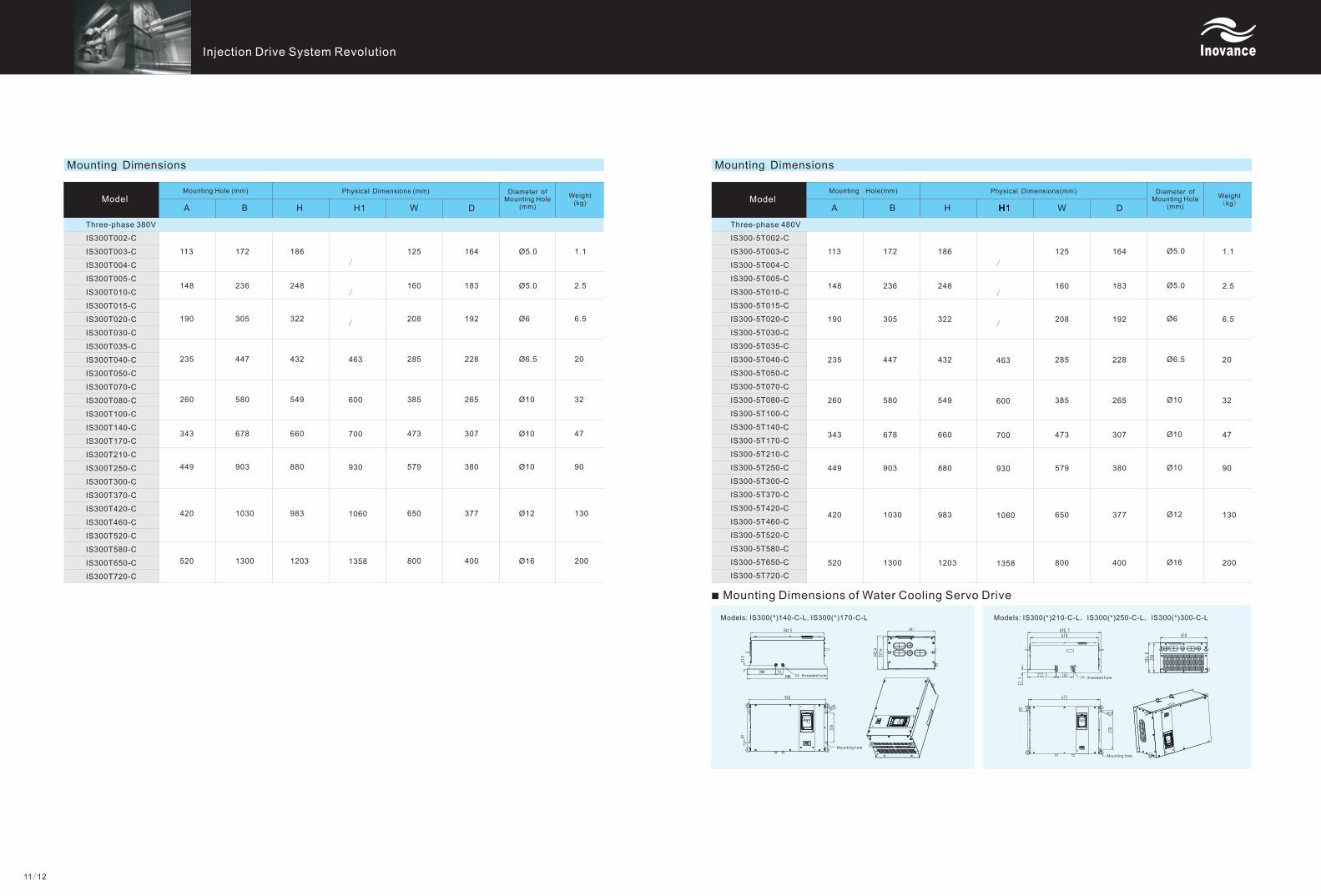
Mounting Dimensions
Diameter ofMounting Hole
(mm)A B H W D
Weightkg)(
Mounting Hole (mm)
Model
Three-phase 380V
IS300T002-C
IS300T003-C
IS300T004-C
IS300T005-C
IS300T010-C
IS300T015-C
IS300T020-C
IS300T030-C
IS300T035-C
IS300T040-C
IS300T050-C
IS300T070-C
IS300T080-C
IS300T100-C
IS300T140-C
IS300T170-C
IS300T210-C
IS300T250-C
IS300T300-C
IS300T370-C
IS300T420-C
IS300T460-C
IS300T520-C
IS300T580-C
IS300T650-C
IS300T720-C
113
148
190
235
260
343
449
420
520
172
236
305
447
580
678
903
1030
1300
186
248
322
432
549
660
880
983
1203
/
/
/
463
600
700
930
1060
1358
125
160
208
285
385
473
579
650
800
164
183
192
228
265
307
380
377
400
Ø
Ø5.0
Ø6
Ø6.5
Ø10
Ø10
Ø10
Ø12
Ø16
5.0 1.1
2.5
6.5
20
32
47
90
130
200
Mounting Dimensions
Diameter ofMounting Hole
(mm)A B H W D
Weight(kg)
Model
Three-phase 480V
IS300-5T002-C
IS300-5T003-C
IS300-5T004-C
IS300-5T005-C
IS300-5T010-C
IS300-5T015-C
IS300-5T020-C
IS300-5T030-C
IS300-5T035-C
IS300-5T040-C
IS300-5T050-C
IS300-5T070-C
IS300-5T080-C
IS300-5T100-C
IS300-5T140-C
IS300-5T170-C
IS300-5T210-C
IS300-5T250-C
IS300-5T300-C
IS300-5T370-C
IS300-5T420-C
IS300-5T460-C
IS300-5T520-C
IS300-5T580-C
IS300-5T650-C
IS300-5T720-C
113
148
190
235
260
343
449
420
520
172
236
305
447
580
678
903
1030
1300
186
248
322
432
549
660
880
983
1203
/
/
/
463
600
700
930
1060
1358
125
160
208
285
385
473
579
650
800
164
183
192
228
265
307
380
377
400
Ø
Ø5.0
Ø6
Ø6.5
Ø10
Ø10
Ø10
Ø12
Ø16
5.0 1.1
2.5
6.5
20
32
47
90
130
200
■ Mounting Dimensions of Water Cooling Servo Drive
Models: IS300(*)140-C-L, IS300(*)170-C-L Models: IS300(*)210-C-L, IS300(*)250-C-L, IS300(*)300-C-L
11/12
Physical Dimensions (mm)
threaded hole
Mounting hole
threaded hole
Mounting hole
Mounting Hole(mm) Physical Dimensions(mm)
H1H1H1H1H1

Injection System Revolution Drive
Naming Rules
ISM G1-30D 15C D-R1 3 1 F① ② ③ ④ ⑤ ⑥ ⑦ ⑧ ⑨
① Series
ISM: IS series servo motor
②
G1: 200
G2: 266×266
Feature
frame
frame
×200
③ Rated power
It is represented by a letter and a digit.
A: ×1
B: ×10
C: ×100
D: ×1000
E: ×10000
For example:
15C: 1500W
30D: 30000W
④ Rated speed
A:×1
B:×10
C:×100
D:×1000
E:×10000
For example:
15C:1500rpm
20C:2000rpm
It is represented by a letter and a digit.
⑥ Encoder type
R1: One-pair-pole resolver
U1: 2500-resolution wire-saving
incremental encoder
⑨ Customized feature
X: Natural cooling
F: Forced air cooling
⑧ Brake, decelerator & oil seal
1: Oil seal
⑦
1: Optical shaft
3: Solid shaft with keyand thread
Axis connection mode
⑤ Voltage level
D: 400V
※ Definition of motor duty type:
The duty type of motor is a description of its load bearing status, including startup, electric braking, empty load and blackout stop, and the duration and sequence of such status.
S1 duty type: indicates a continuous duty type. The motor works continuously and is able to achieve thermal stability within the operation period under a steady load.
S4 duty type: indicates an intermittent duty type. The motor works based on a series of same working periods. Each period includes the startup time
(which impacts significantly on temperature rise), operation time under a constant load, and the time for blackout stop.
※ We can provide customized products based on customers' actual requirements.
※ Generally, the delivery period of servo motors is 30 working days.
Features
Performance Specifications
ISMG1-95C15CD-R131F
ISMG1-11D17CD-R131F
ISMG1-12D20CD-R131F
ISMG1-14D15CD-R131F
ISMG1-16D17CD-R131F
ISMG1-18D20CD-R131F
ISMG1-22D15CD-R131F
ISMG1-24D17CD-R131F
ISMG1-28D20CD-R131F
ISMG1-30D15CD-R131F
ISMG1-41D20CD-R131F
55
75
115
150
60
90
135
195
1500
1700
2000
1500
1700
2000
1500
1700
2000
1500
2000
305
296
291
291
296
310
305
296
291
291
310
18
22
24
25
29
31
36
43
47
48
60
19
23
26
30
34
36
41
50
54
61
76
8.5
10.0
11.5
13.0
14.5
17.0
19.0
21.5
25.5
25.0
33.0
9.5
11.0
12.6
14.1
16.0
18.8
22.0
24.0
28.3
30.6
41.0
3.24
2.68
2.39
3.01
2.75
2.55
3.31
2.76
2.53
3.20
2.58
0.203
0.174
0.146
0.194
0.174
0.155
0.203
0.174
0.146
0.194
0.155
160
160
160
230
230
230
340
340
340
450
450
2000
2210
2500
2000
2210
2500
2000
2210
2500
2000
2500
7.5
7.5
7.5
9.0
9.0
9.0
12.0
12.0
12.0
15.0
15.0
8
8
8
8
8
8
8
8
8
8
8
335
334
327
325
328
335
342
332
322
324
334
340
338
331
332
333
340
348
338
328
333
343
Model ①Rated Torque
(Nm)
S1② S4②
Rated Speed(rpm)
Back-EMF(V)
Rated Voltage(V)
S1② S4②
Rated Current(A)
S1② S4②
Rated Power(kW)
S1② S4②
Torque Constant
(Nm/Arms)
Back-EMFConstant(V/rpm)
Max. Torque(Nm)
Max. Speed (rpm)
Rotor Inertia
2 -3(kgm 10 )
No.of Poles
★ Note: 1. Models in grey shading are general ones for servo pump system.
2. ① Models of forced-air-cooling motors are defined by S4 duty type; models of natural-cooling motors are defined by S1 duty type.
② S1/S4 indicates S1/S4 duty type.
■ISMG1 Servo Motor (200×200 frame/forced air cooling)
■ISMG2 266×266 Servo Motor ( Frame/Forced air cooling)
ISMG2-20D15CD-R131F
ISMG2-23D17CD-R131F
ISMG2-27D20CD-R131F
ISMG2-31D15CD-R131F
ISMG2-36D17CD-R131F
ISMG2-42D20CD-R131F
ISMG2-42D15CD-R131F
ISMG2-48D17CD-R131F
ISMG2-57D20CD-R131F
ISMG2-60D15CD-R131F
ISMG2-68D17CD-R131F
ISMG2-80D20CD-R131F
ISMG2-80D15CD-R131F
ISMG2-91D17CD-R131F
ISMG2-11E20CD-R131F
1500
1700
2000
1500
1700
2000
1500
1700
2000
1500
1700
2000
1500
1700
2000
291
296
310
305
296
291
291
296
310
305
296
291
291
329
310
346
351
365
358
349
344
341
346
360
353
344
339
334
372
353
353
358
372
364
355
350
348
353
367
360
351
346
341
379
360
41
45
51
56
65
78
79
88
99
110
129
154
149
149
187
45
50
57
65
76
92
92
102
115
125
145
174
173
173
216
18.2
20.6
24.3
26.7
30.3
35.6
36.1
40.9
48.2
53.4
60.5
71.2
69.1
78.3
92.1
20.4
23.1
27.2
31.4
35.6
41.9
42.4
48.1
56.5
60.5
68.5
80.6
80.1
90.8
106.8
2.98
2.68
2.39
3.13
2.68
2.24
2.98
2.68
2.39
3.13
2.68
2.24
2.98
2.98
2.39
0.194
0.174
0.155
0.203
0.174
0.145
0.194
0.174
0.155
0.203
0.174
0.145
0.194
0.194
0.155
325
325
325
488
488
488
650
650
650
975
975
975
1300
1300
1300
1800
2040
2400
1800
2040
2400
1800
2040
2400
1800
2040
2400
1800
2040
2400
22.1
22.1
22.1
29.6
29.6
29.6
36.8
36.8
36.8
50.0
50.0
50.0
64.0
64.0
64.0
8
8
8
8
8
8
8
8
8
8
8
8
8
8
8
116
170
230
340
440
130
200
270
385
510
■ISMG1 Servo Motor (200×200 Frame/Natural cooling)
Rated Torque(Nm)
S1② S4②
1500
1700
2000
1500
1700
2000
1500
1700
2000
1500
2000
305
296
291
291
296
310
305
296
291
291
310
3.24
2.68
2.39
3.01
2.75
2.55
3.31
2.76
2.53
3.20
2.58
8
8
8
8
8
8
8
8
8
8
8
RSpeed(rpm)
ated Back-EMF
V)(
Rated VoltageV)(
S1② S4②
Rated CurrentA)(
S1② S4②
Rated PowerkW)(
S1② S4②
TorqueConstantNm/Arms)(
Back-EMFConstant
V/rpm)(
Max.Torque
Nm)(
Max. Speed
rpm)(
No. of Poles
ISMG1-55C15CD-R131X
ISMG1-62C17CD-R131X
ISMG1-75C20CD-R131X
ISMG1-75C15CD-R131X
ISMG1-85C17CD-R131X
ISMG1-11D20CD-R131X
ISMG1-11D15CD-R131X
ISMG1-12D17CD-R131X
ISMG1-15D20CD-R131X
ISMG1-13D15CD-R131X
ISMG1-18D20CD-R131X
325
318
313
312
315
325
325
316
308
309
323
330
325
320
320
322
330
332
322
315
315
328
11
13
15
16
18
20
21
26
28
28
35
14
17
19
21
23
25
27
32
34
35
43
5.5
6.2
7.5
7.5
8.5
11.0
11.0
12.0
15.0
13.0
18.5
7.0
8.0
9.5
9.7
11.0
13.0
13.7
15.5
18.0
18.0
23.5
0.203
0.174
0.146
0.194
0.174
0.155
0.203
0.174
0.145
0.194
0.155
160
160
160
230
230
230
340
340
340
450
450
2000
2210
2500
2000
2210
2500
2000
2210
2500
2000
2500
7.5
7.5
7.5
9.0
9.0
9.0
12.0
12.0
12.0
15.0
15.0
Rated TorqueNm)(
S1② S4②
Rated Speed
rpm)(
Back-EMF
V)(
Rated VoltageV( )
S1② S4②
Rated CurrentA)(
S1② S4②
Rated PowerkW)(
S1② S4②
TorqueConstantNm/Arms)(
Back-EMFConstant
V/rpm)(
Max.Torque
Nm)(
Max.Speed
rpm)(
No.of Poles
■ISMG2 Servo Motor (266×266 frame/Natural cooling)
1500
1700
2000
1500
1700
2000
1500
1700
2000
1500
1700
2000
1500
1700
2000
291
296
310
305
296
291
291
296
310
305
296
291
291
329
310
2.98
2.68
2.39
3.13
2.68
2.24
2.98
2.68
2.39
3.13
2.68
2.24
2.98
2.98
2.39
0.194
0.174
0.155
0.203
0.174
0.145
0.194
0.174
0.155
0.203
0.174
0.145
0.194
0.194
0.155
325
325
325
488
488
488
650
650
650
975
975
975
1300
1300
1300
1800
2040
2400
1800
2040
2400
1800
2040
2400
1800
2040
2400
1800
2040
2400
22.1
22.1
22.1
29.6
29.6
29.6
36.8
36.8
36.8
50.0
50.0
50.0
64.0
64.0
64.0
8
8
8
8
8
8
8
8
8
8
8
8
8
8
8
★ Note: 1. Models in grey shading are general ones for servo pump system.
2. ①Models of forced-air-cooling motors are defined by S4 duty type; models of natural-cooling motors are defined by S1 duty type.
② S1/S4 indicates S1/S4 duty type.
ISMG2-13D15CD-R131X
ISMG2-14D17CD-R131X
ISMG2-17D20CD-R131X
ISMG2-18D15CD-R131X
ISMG2-21D17CD-R131X
ISMG2-24D20CD-R131X
ISMG2-24D15CD-R131X
ISMG2-28D17CD-R131X
ISMG2-33D20CD-R131X
ISMG2-35D15CD-R131X
ISMG2-39D17CD-R131X
ISMG2-46D20CD-R131X
ISMG2-43D15CD-R131X
ISMG2-49D17CD-R131X
ISMG2-58D20CD-R131X
35
48
70
89
43
60
85
110
80
115
155
220
275
95
140
185
260
330
321
326
340
332
323
318
316
321
335
328
319
314
309
347
328
326
331
345
338
329
324
321
326
340
333
324
319
314
352
333
29
32
36
38
45
54
54
60
67
72
84
101
94
94
117
34
37
42
46
54
65
64
71
80
85
99
119
112
112
140
12.6
14.2
16.8
18.1
20.5
24.1
24.3
27.6
32.5
34.6
39.2
46.1
43.2
49.0
57.6
14.9
16.9
19.9
22
24.9
29.3
29.1
32.9
38.7
40.8
46.3
54.5
51.8
58.7
69.1
ISMG Series General-purpose Servo Motor
13/14
Rated Torque(Nm)
S1② S4②
Rated Speed(rpm)
Back-EMF(V)
Rated Voltage(V)
S1② S4②
Rated Current(A)
S1② S4②
Rated Power(kW)
S1② S4②
Torque Constant
(Nm/Arms)
Back-EMFConstant(V/rpm)
Max. Torque (Nm)
Max. Speed (rpm)
No.ofPolesModel①
Model①
Model①
Rotor Inertia
2 -3(kgm 10 )
Rotor Inertia
2 -3kgm 10( )
RotorInertia
kgm210 -3( )
Use ANSOFT for simulation design, which brings excellent magnetic performance;
Use high-performance Nd-Fe-N materials for excitation, with less iron and copper losses, higher efficiency and less heating
Able to maintain highly efficient operation within a wide speed and load range;
A wide range of capacity specifications and rated speeds for options;
Customization in design (such as hollow shaft motor) is available;
Use a solid and durable resolver as the speed feedback unit which can work long in the environment with high temperature, vibration
and oil stains
With a built-in thermal resistor which provides overheat protection to the motor

Injection System Revolution Drive
ISMG1-14D10CD-R131FISMG1-22D15CD-R131FISMG1-24D17CD-R131FISMG1-28D20CD-R131F
ISMG1-20D10CD-R131FISMG1-30D15CD-R131FISMG1-41D20CD-R131F
395
230
471
305
550
380
L
K
Model
Item
360
190
■ISMG1 Servo Motor (200×200 frame/forced air cooling)
ISMG1-95C15CD-R131FISMG1-11D17CD-R131FISMG1-12D20CD-R131F
ISMG1-14D15CD-R131FISMG1-16D17CD-R131FISMG1-18D20CD-R131F
ISMG1-22D15CD-R131FISMG1-24D17CD-R131FISMG1-28D20CD-R131F
ISMG1-30D15CD-R131FISMG1-41D20CD-R131F
■ISMG2 Servo Motor (266×266 frame/forced air cooling)
ISMG1-14D10CD-R131FISMG1-22D15CD-R131FISMG1-24D17CD-R131FISMG1-28D20CD-R131F
ISMG1-20D10CD-R131FISMG1-30D15CD-R131FISMG1-41D20CD-R131F
■ISMG1 Servo Motor (200×200 frame/natural cooling)
ISMG1-14D10CD-R131FISMG1-22D15CD-R131FISMG1-24D17CD-R131FISMG1-28D20CD-R131F
ISMG1-20D10CD-R131FISMG1-30D15CD-R131FISMG1-41D20CD-R131F
L
K
ModelItem
ISMG1-55C15CD-R131XISMG1-62C17CD-R131XISMG1-75C20CD-R131X
ISMG1-75C15CD-R131XISMG1-85C17CD-R131XISMG1-11D20CD-R131X
ISMG1-11D15CD-R131XISMG1-12D17CD-R131XISMG1-15D20CD-R131X
ISMG1-13D15CD-R131XISMG1-18D20CD-R131X
295
190
330
230
406
305
485
380
15/16
Mounting Dimensions
L
K
Model
Item
ISMG2-20D15CD-R131FISMG2-23D17CD-R131FISMG2-27D20CD-R131F
ISMG2-31D15CD-R131FISMG2-36D17CD-R131FISMG2-42D20CD-R131F
ISMG2-42D15CD-R131FISMG2-48D17CD-R131FISMG2-57D20CD-R131F
ISMG2-60D15CD-R131FISMG2-68D17CD-R131FISMG2-80D20CD-R131F
ISMG2-80D15CD-R131FISMG2-91D17CD-R131FISMG2-11E20CD-R131F
475
200
525
250
575
300
675
400
780
500
ISMG1-14D10CD-R131FISMG1-22D15CD-R131FISMG1-24D17CD-R131FISMG1-28D20CD-R131F
ISMG1-20D10CD-R131FISMG1-30D15CD-R131FISMG1-41D20CD-R131F
L
K
Model
Item
■ISMG2 Servo Motor (266×266 frame/natural cooling)
ISMG2-13D15CD-R131XISMG2-14D17CD-R131XISMG2-17D20CD-R131X
ISMG2-18D15CD-R131XISMG2-21D17CD-R131XISMG2-24D20CD-R131X
ISMG2-24D15CD-R131XISMG2-28D17CD-R131XISMG2-33D20CD-R131X
ISMG2-35D15CD-R131XISMG2-39D17CD-R131XISMG2-46D20CD-R131X
ISMG2-43D15CD-R131XISMG2-49D17CD-R131XISMG2-58D20CD-R131X
345
200
395
250
445
300
550
400
650
500
4-
4-
4-
2-
Flow( )L/min
Pressure( )2kgf/cm
Configuration Example of Servo Pump System
Max. Speed(rpm)
Requirements
140
160
175
Displacement of Pump ( ) ml/min Motor Model Drive Model
Configuration
62
69
84
100
126
144
180
225
270
315
360
450
504
62
69
84
100
126
144
180
225
270
315
360
450
62
69
84
100
126
144
180
225
270
315
360
2200
2200
2100
2000
2000
1800
1800
1800
1800
1800
1800
1800
1800
2200
2200
2100
2000
2000
1800
1800
1800
1800
1800
1800
1800
2200
2200
2100
2000
2000
1800
1800
1800
1800
1800
1800
28.0
31.5
40.0
50.0
63.0
80.0
100.0
125.0
150.0
175.0
200.0
250.0
280.0
28.0
31.5
40.0
50.0
63.0
80.0
100.0
125.0
150.0
175.0
200.0
250.0
28.0
31.5
40.0
50.0
63.0
80.0
100.0
125.0
150.0
175.0
200.0
ISMG1-12D20CD-R131F
ISMG1-12D20CD-R131F
ISMG1-16D17CD-R131F
ISMG1-16D17CD-R131F
ISMG1-24D17CD-R131F
ISMG1-30D15CD-R131F
ISMG1-30D15CD-R131F
ISMG2-42D15CD-R131F
ISMG2-42D15CD-R131F
ISMG2-60D15CD-R131F
ISMG2-60D15CD-R131F
ISMG2-80D15CD-R131F
ISMG2-80D15CD-R131F
ISMG1-12D20CD-R131F
ISMG1-18D20CD-R131F
ISMG1-16D17CD-R131F
ISMG1-24D17CD-R131F
ISMG1-24D17CD-R131F
ISMG1-30D15CD-R131F
ISMG2-42D15CD-R131F
ISMG2-60D15CD-R131F
ISMG2-60D15CD-R131F
ISMG2-60D15CD-R131F
ISMG2-80D15CD-R131F
ISMG2-80D15CD-R131F
ISMG1-12D20CD-R131F
ISMG1-18D20CD-R131F
ISMG1-16D17CD-R131F
ISMG1-24D17CD-R131F
ISMG1-24D17CD-R131F
ISMG1-30D15CD-R131F
ISMG2-42D15CD-R131F
ISMG2-60D15CD-R131F
ISMG2-60D15CD-R131F
ISMG2-80D15CD-R131F
ISMG2-80D15CD-R131F
IS300T020-C
IS300T030-C
IS300T030-C
IS300T040-C
IS300T050-C
IS300T050-C
IS300T070-C
IS300T080-C
IS300T080-C
IS300T100-C
IS300T140-C/IS300T140-C-L
IS300T140-C/IS300T140-C-L
IS300T170-C/IS300T170-C-L
IS300T030-C
IS300T030-C
IS300T035-C
IS300T040-C
IS300T050-C
IS300T050-C
IS300T070-C
IS300T080-C
IS300T100-C
IS300T140-C/IS300T140-C-L
IS300T140-C/IS300T140-C-L
IS300T170-C/IS300T170-C-L
IS300T030-C
IS300T035-C
IS300T040-C
IS300T050-C
IS300T050-C
IS300T070-C
IS300T080-C
IS300T100-C
IS300T100-C
IS300T140-C/IS300T140-C-L
IS300T140-C/IS300T140-C-L
※ Models above IS300T070-C (inclusive) and IS300T140-C-L (inclusive) need to be configured with an external braking unit (refer to P7).
※ The above configuration is an example. Specifications vary with customer requirements. For further information, please contact Inovance marketing engineers.

Models & Specifications
1. Torque Motor
■Model:
ISMD1-10B18BA-I120X
■Specifications:
Rated voltage: 100V
Rated current: 1A
Rated torque: 5.4Nm
Rated speed: 180rpm
Rated frequency: 24Hz
Rated power: 100W
■Mounting dimensions:
2. Drive
■Model:
NICE-D-A-S0P2
■Specifications:
Input: single-phase 220VAC, 50Hz
Output: 0~220VAC, 0~50Hz
Output current: 1.3A
■Mouting Dimensions:
Automatic material feeding is not convenient for large-tonnage injection molding
machines. Operator needs to open the machine door to feed materials manually.
Traditional control solutions:
Solution A: The pump of the injection molding machine provides power and works with
additionally installed reversing valve and hydro-cylinder to realize door opening.
Solution B: A separate air compressor provides power and works with additionally
installed reversing valve and hydro-cylinder to realize door opening.
Solution C: The AC asynchronous motor, decelerator and inverter together provide power
to realize door opening through computer board
signals and the synchronous belt.
Disadvantages of the above solutions:
Solution A: To realize smooth operation switchover, the hydraulic circuit system is complicated and
requires coordination of dedicated software from the computer.
Solution B: An additional air compressor is required. In addition, operations cannot be smoothly
switched, which brings great mechanical chocks, thus causing relatively high error rate.
Solution C: Speed adjustment is conducted through the inverter, which realizes smooth operation
switchover.
The above three solutions share a common disadvantage: they all cannot guarantee safe operations.
When the machine door closes, the injection molding machine using these solutions cannot realize reverse door opening through a
preset resistance torque, to guarantee personal security (anti-pinch function).
Inovance Solution
Use a servo motor (with encoder feedback) to realize accurate position, speed and torque control. The open/close curve of the injection molding machine can be set through parameters of the servo drive. With this easiest external logic, smooth operation of the machine door can be realized, and anti-pinch protection is guaranteed.
Our solution has the following advantages:
The servo torque motor is configured with encoder feedback,
and thus the decelerator is not necessary.
Direct drive, sensitive and accurate control;
Small size, low weight, easy installation, and convenient
maintenance
Operator can program the open/close curve through the servo
drive, which guarantees smooth operation of the machine door.
The built-in encoder can inspect the current position.
The open/close curve can be configured with 4 switchover points
(opening limit, opening speed-down, closing speed-down and
closing limit), which greatly reduce the programming workload.
Reliable anti-pinch function, not requiring safety seal
The motor torque can be accurately inspected. When the motor’s
output torque reaches a preset value, the machine door re-opens, thus offering anti-pinch protection.
This system complies with relevant requirements of the national standard GB-7588 for elevator industry as well as the 2009 new injection
molding machine standard, and has been verified by mass applications.
Intelligent door-width self-tuning, thus saving two speed-down switches
With the built-in encoder, the servo drive performs door-width self-tuning once when powered on. The door-width is automatically
recorded. Operator can set the opening/closing limit positions and speed-down position, thus saving two physical proximity switches for
speed-down. This reduces costs and eliminates two potential errors.
Injection System Revolution Drive
Electric-Door System Solution for Servo Injection Molding Machine
17/18
2-Φ5
安装孔
2-6.5*5
197
205
129 147
风扇
66
Cable resistance: 31Ω
Cable inductance: 105mH
Cable back-EMF constant: 8.76V/rad/s
IP code: IP44
Insulation grade: B
Duty type: S4
Specialized servo drive(with control logic for door machine)
Torque motor
Belt
Door of injection molding machine
Overview
Fan
Mounting hole

Injection System Revolution Drive
Overview
When manufacturing double-color products, the injection molding machine requires the mould to realize 180° rotation for injecting sizing
materials of two different colors.
Traditional control solution:
Gyration of the turnplate is realized through the hydraulic motor and the rotation direction is realized through a directional valve. When
the turnplate closes to the preset position, it speeds down and stops at the preset position. A location pin is used for forced positioning.
Disadvantages:
1. Inaccurate positioning
The hydraulic motor cannot realize position control; the positioning position varies with the size of the mould.
2. Time-consuming
The turnplate must speed down when closing to the preset position, in order to finally stop on an area where the location pin works.
3. Large shock
The total weight of the turnplate and mould is relatively large. Thus, it causes large mechanical shock when the rotation stops since there
is no speed-up/down and curve operation processes. This will reduce the machine’s service life.
Use a servo motor (with encoder feedback) to realize accurate position and speed control. Operator can set the positioning speed and
angle through the servo drive. With this easiest external logic, the turnplate can realize fast, smooth and accurate operations.
Our solution has the following advantages:
High-speed accurate positioning, not requiring the
location pin
A high-dynamic responsive servo takes the place of the
location pin to realize accurate positioning, reducing the
positioning period by at least 1 s/time.
No-shock positioning
Smooth speed-up/down transition can be realized through the
perfect speed-up/down curve inside the servo, reducing the
mechanical shock to the least.
Positioning speed/angle adjusting through servo drive; no
need to modify computer program
The positioning speed can be set through the servo drive or
given by the potentiometer.
Other functions:
Origin return: The servo drive automatically performs origin return by triggering, avoiding origin losses due to power-on/off.
Forward/Reverse jog: convenient for mould setting/testing and troubleshooting
Forward/Reverse speed limiting: applied to vertical reciprocating linear machines
Double-Color Revolving Mold System Solution for InjectionMolding Machine
Overview
When the injection molding machine works, over-long melting process will directly lead to extension of the working period. In order to
improve manufacturing efficiency, the melting operation is usually performed synchronously with mould-opening/closed or other
operation to save time. This is called “synchronous melting”.
Traditional control solutions:
1. Use an independent hydraulic system to realize synchronous melting.
2. Use a shunt/merging system to realize synchronous melting.
For a large-tonnage injection molding machine driven by multiple pumps, certain pumps are spared by the magnetic valve to drag the
melting motor; the rest pumps supply power for other operations.
Disadvantages:
1. Large power consumption
Melting through the hydraulic motor is of low efficiency and large power consumption.
2. Complicated structure
The entire machine structure is too complicated when using a hydraulic system for synchronous melting.
3. Unstable speed
The internal leakage of the melting motor varies with different loads, which leads to unstable rotary speed.
4. Not suitable for manufacturing purifier products
Use a servo motor (with encoder feedback) to realize accurate speed control. Operator can set the melting speed through the computer
program. With this easiest structure, synchronous melting is realized.
Servo motors for synchronous melting:
1. Servo motor + decelerator
2. Large-torque servo motor
Our solution has the following advantages:
Energy-saving
Direct drive by servo motor brings higher efficiency and lower energy consumption.
Simple structure
The drive structure is simple, including only the servo drive and servo motor
(or servo motor + decelerator).
Steady speed
Closed-loop control is realized through encoder feedback, thus ensuring a steady speed.
Suitable for manufacturing purifier products (such as medical items)
In case of using a large-torque servo motor, there is an additional advantage:
Maintenance-free
The decelerator is not necessary. Thus, the machine does not require lubrication or
maintenance.
Synchronous Melting Solution for Servo Injection Molding Machine
19 20/
Servo drive
Servo motor
Decelerator Screw
Servo drive
Torque motor
Screw
DeceleratorGear
speed-downMold rotationmechanism
Servo motor
Servo driveWith control logic for revolving mold( )
Inovance Solution
Inovance Solution
Injection System Revolution Drive
Full-Electric Injection Molding Machine SolutionIn recent years, injection molding machines develop in the trend of electromotion and high speed. Compared with traditional full-hydraulic injection molding
machines, full-electric injection molding machines have totally abandoned the hydraulic system and use servo motors to drive all operations. Full-electric
injection molding machines are energy-saving, environment-friendly, noiseless, accurate, fast and stable. They possess more excellent controllable
mechanism, repeatability and technique stability. Besides, the life cycle costs are optimized. If the torque motor technology is used on the injection device, the
working speed and efficiency of the injection molding machine will be greatly improved. Obviously, full-electric injection molding machines will be the
development trend of the injection molding machine industry.
Inovance has always been dedicated to R&D of drive and control technologies. With years of experience in plastics machinery applications, we have applied
our accumulation of PLC and servo drive technologies in the injection molding field, and have released a comprehensive solution of full-electric injection
molding machine. Our complete product range, including servo drive, servo motor, PM synchronous torque motor and PLC, can fulfill all requirements for drive
and control of full-electric injection molding machines.
1. Advantages of Full-Electric Injection Molding Machine
1) High accuracy and excellent repeatability
The full-electric injection molding machine is driven by the servo motor and uses ball screw and synchronous gear belt for transmission, which greatly improves
the control accuracy of the power system. Controlled by the re-circulated computer system, the injection position accuracy can reach 0.01mm.
2) Short manufacturing cycle
The full-electric injection molding machine uses multiple independent servo motors to perform mold-locking, injection, pressure holding, storing and ejection
operations. The traditional machine uses a single hydraulic system to perform all these operations one after another. Compared with traditional machine, the
full-electric machine is able to perform mold-opening and storing operations at the same time, or perform injection operation immediately after mold-closing,
thus greatly shortening the manufacturing cycle.
3. Energy-saving
The full-electric injection molding machine is driven by the servo motor which consumes little power and won't generate tremendous heat during operation.
Thus, the water cooling system is not necessary. Besides, full-electric injection molding machine does not bring oil stains to the working environment, and thus
can manufacture accurate components with excellent effect. This successfully avoids environmental pollution and greatly reduces mechanical noise.
2. Main Parts of Full-Electric Injection Molding Machine
Servo motors (with compatible servo drive) for mold-opening/closed, melting, injection, mold setting, ejection, motion of injection
platform, etc
We can offer related products and solutions.
Energy-saving: Servo motors work only when required, thus saving above 60% power more than traditional hydraulic injection
machine.
High repeatability accuracy: The IS500 servo system is able to realize highly accurate position/speed control. The accuracy of
ball screws can reach nanometer level; the deviation of the system's positioning repeatability accuracy is ±0.01%.
The built-in algorithm of the servo system realizes control of the injection formation technique; distributed topological structure
decreases the requirements for the control system.
Accelerated speed of the servo system is under constant control. When the ejection speed is at a low or medium level, the system
initiates an ejection speed at the same slope as the maximum speed, thus effectively preventing burns of resins and induction of air.
Mdularized H3U series PLC is used for logic and temperature control of the entire machine, which makes programming more
flexible and accountable.
A dedicated highly-accurate temperature control module is used, thus controlling the temperature deviation within ±0.5℃.
The pressure wave form of qualified products is used in the phases of ejection and pressure holding for trace and control. Thus,
products can be manufactured in a more steady way.
Full-Electric Injection Molding Machine Solution
Fu
ll-E
lec
tric In
jec
tion M
old
ing M
ach
ine C
on
trol S
yste
m
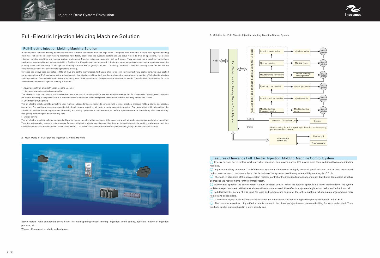
HMI
Injection servo drive
Melt servo drive
Mould moving servo drive
Ejector pin servo drive
Injection unit servo drive
Mould adjusting frequency control
Injection motor
Melting motor
Mould opening/closing motor
Ejector pin motor
Injection motor
Mould adjusting motor
SensorPressure Translation Unit
(Mould closing, injection, ejector pin, injection station moving) postion electrical sensor
Temperature control unit
Heating unit
Thermocouple
Analog
Digital
21/22
Bu
ilt-in in
jectio
n m
old
ing p
roce
ss c
on
trol a
lgo
rithm
3. Solution for Full-Electric Injection Molding Machine Control System
Features of Inovance Full-Electric Injection Molding Machine Control System
Swash-plate
Swash-plate
Swash-plate
Swash-plate
Swash-plate
Swash-plate