Embed Size (px)
Citation preview
Drillmec HH-300 spec.
HH‐300
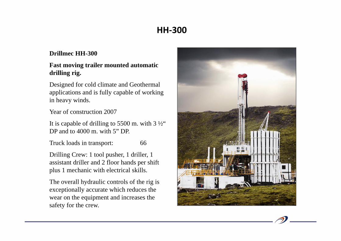
Drillmec HH-300
Fast moving trailer mounted automatic drilling rig.
Designed for cold climate and Geothermal applications and is fully capable of working in heavy winds.
Year of construction 2007
It is capable of drilling to 5500 m. with 3 ½“ DP and to 4000 m. with 5” DP.
Truck loads in transport: 66
Drilling Crew: 1 tool pusher, 1 driller, 1 assistant driller and 2 floor hands per shift plus 1 mechanic with electrical skills.
The overall hydraulic controls of the rig is exceptionally accurate which reduces the wear on the equipment and increases the safety for the crew.
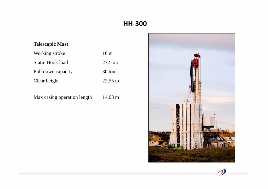
Telescopic Mast
Working stroke 16 m
Static Hook load 272 ton
Pull down capacity 30 ton
Clear height 22,55 m
Max casing operation length 14,63 m
HH‐300
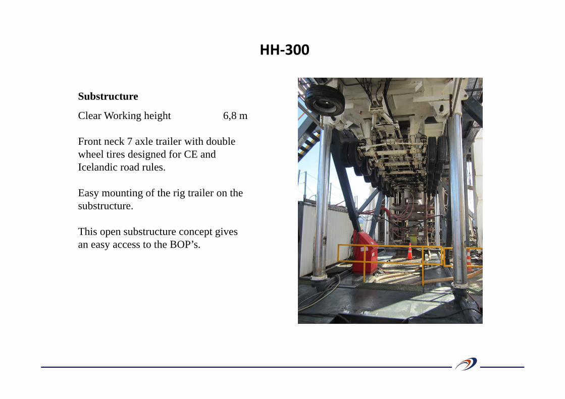
Substructure
Clear Working height 6,8 m
Front neck 7 axle trailer with double wheel tires designed for CE and Icelandic road rules.
Easy mounting of the rig trailer on the substructure.
This open substructure concept gives an easy access to the BOP’s.
HH‐300
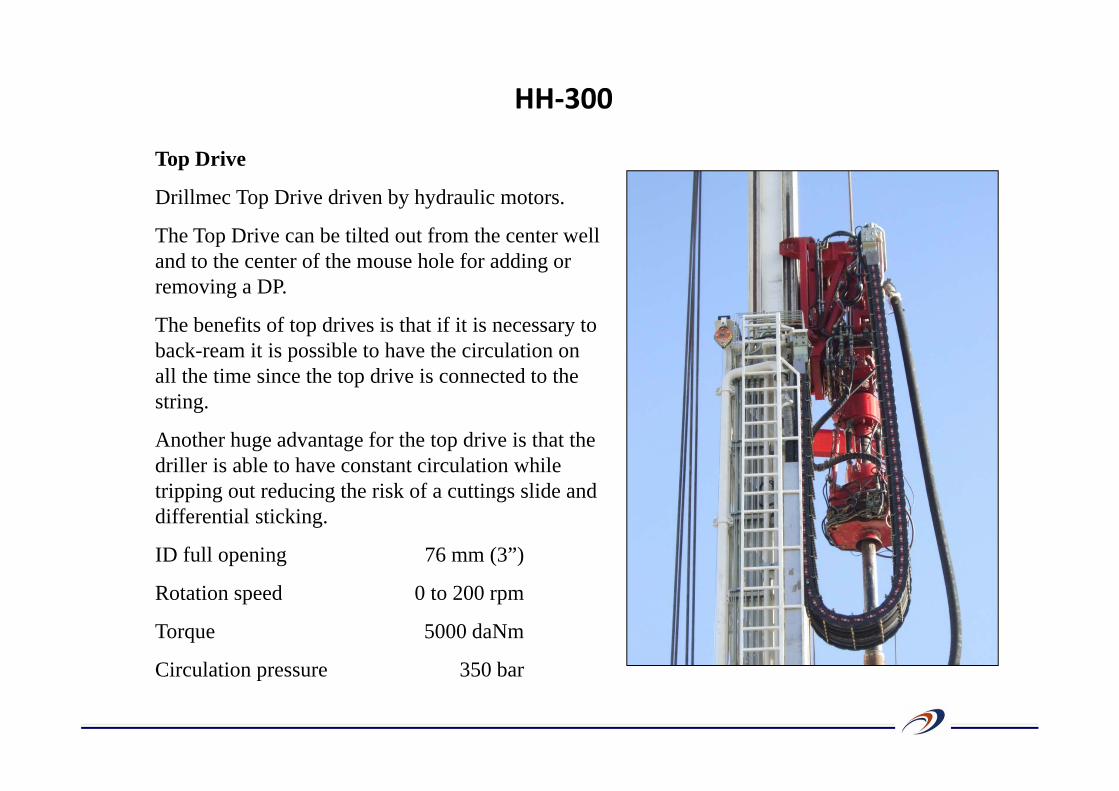
Top Drive
Drillmec Top Drive driven by hydraulic motors.
The Top Drive can be tilted out from the center well and to the center of the mouse hole for adding or removing a DP.
The benefits of top drives is that if it is necessary to back-ream it is possible to have the circulation on all the time since the top drive is connected to the string.
Another huge advantage for the top drive is that the driller is able to have constant circulation while tripping out reducing the risk of a cuttings slide and differential sticking.
ID full opening 76 mm (3”)
Rotation speed 0 to 200 rpm
Torque 5000 daNm
Circulation pressure 350 bar
HH‐300
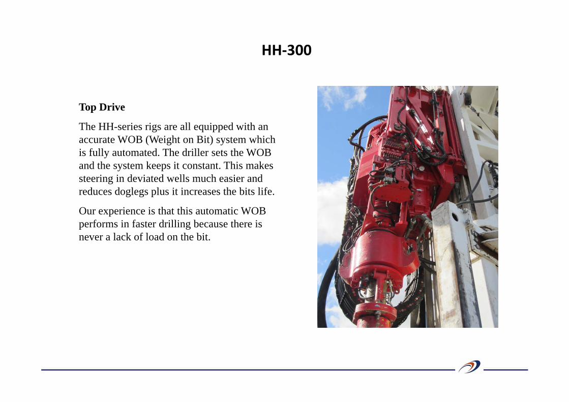
Top Drive
The HH-series rigs are all equipped with an accurate WOB (Weight on Bit) system which is fully automated. The driller sets the WOB and the system keeps it constant. This makes steering in deviated wells much easier and reduces doglegs plus it increases the bits life.
Our experience is that this automatic WOB performs in faster drilling because there is never a lack of load on the bit.
HH‐300
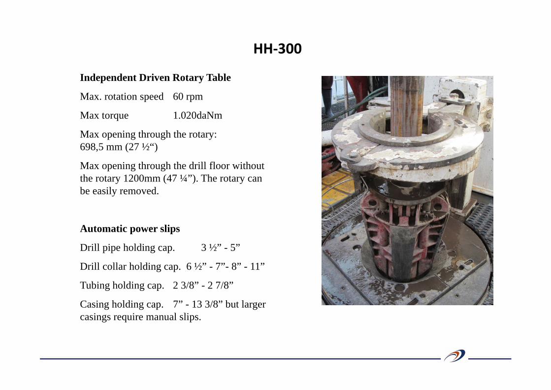
Independent Driven Rotary Table
Max. rotation speed 60 rpm
Max torque 1.020daNm
Max opening through the rotary: 698,5 mm (27 ½“)
Max opening through the drill floor without the rotary 1200mm (47 ¼”). The rotary can be easily removed.
Automatic power slips
Drill pipe holding cap. 3 ½” - 5”
Drill collar holding cap. 6 ½” - 7”- 8” - 11”
Tubing holding cap. 2 3/8” - 2 7/8”
Casing holding cap. 7” - 13 3/8” but larger casings require manual slips.
HH‐300
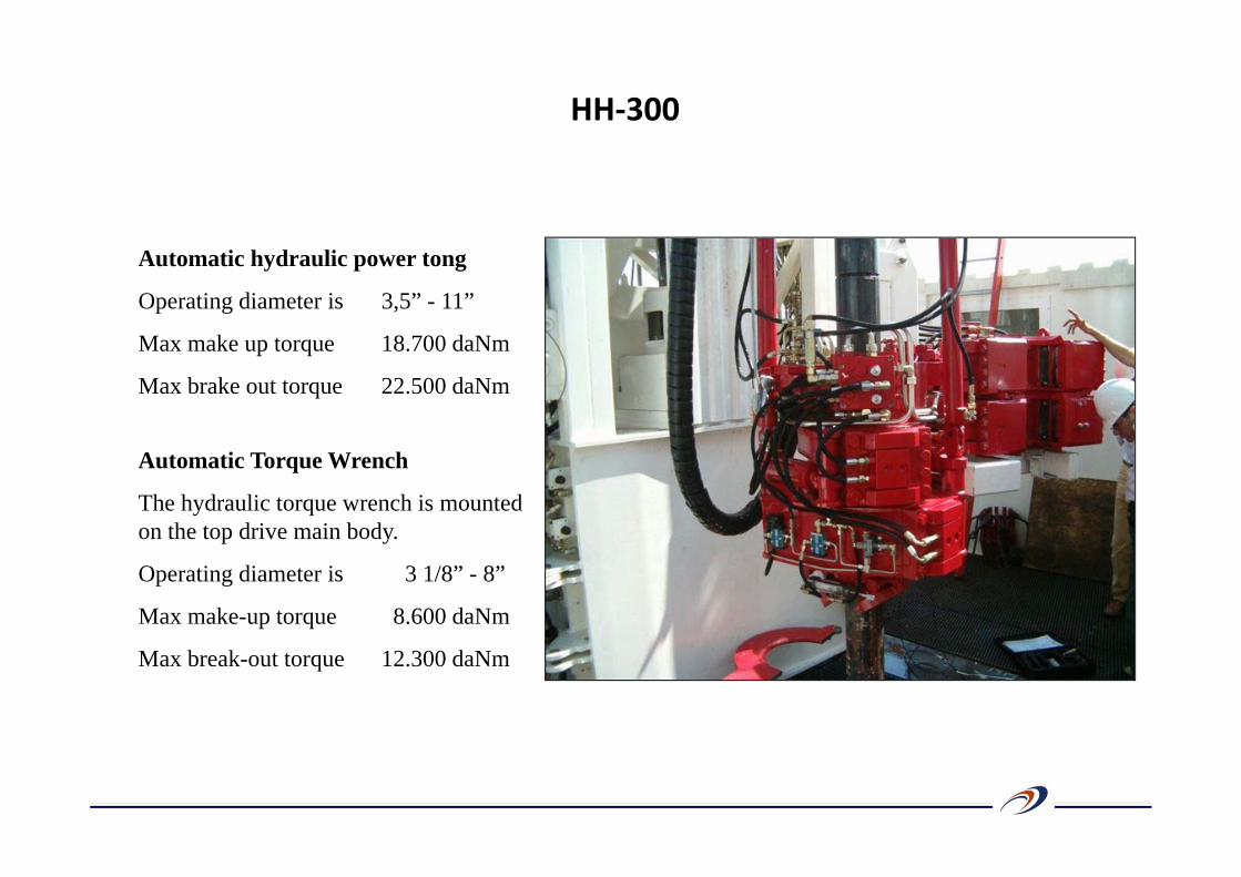
Automatic hydraulic power tong
Operating diameter is 3,5” - 11”
Max make up torque 18.700 daNm
Max brake out torque 22.500 daNm
Automatic Torque Wrench
The hydraulic torque wrench is mounted on the top drive main body.
Operating diameter is 3 1/8” - 8”
Max make-up torque 8.600 daNm
Max break-out torque 12.300 daNm
HH‐300
HH‐300
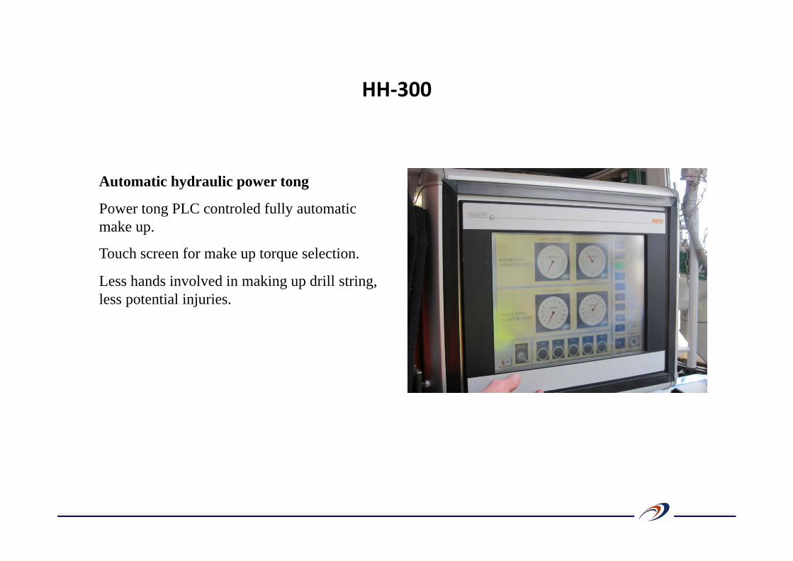
Automatic hydraulic power tong
Power tong PLC controled fully automatic make up.
Touch screen for make up torque selection.
Less hands involved in making up drill string, less potential injuries.
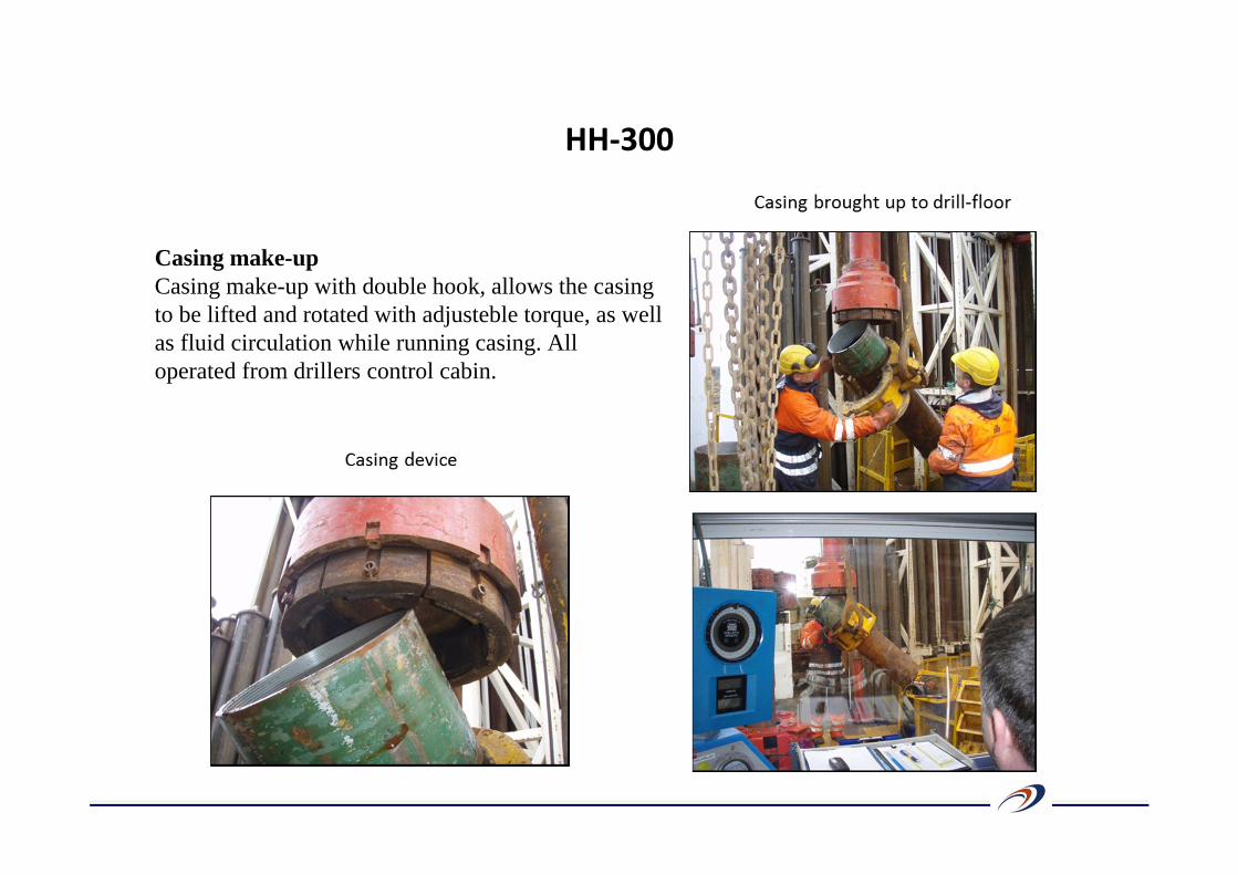
Casing make-up
Running the casing in is an extremely simple task when using the HH-series. The rigs are equipped with a casing make-up tool which clamps on the casing and screws the casing using the top drive. There is a casing backup slips in the rotary table which holds the casing while making-up. The make-up is remotely operated by the driller inside the control cabin.
A big benefit to this casing make-up device allows us to run-in the casing in windy conditions which reduces the risk of stopping operations because of a strong wind.
The HH-series sophisticated hydraulic height, RPM and torque control minimizes damage of the threads.
The use of this equipment eliminates the need for a special service company to run-in the casing.
HH‐300
HH‐300
Casing make-upCasing make-up with double hook, allows the casing to be lifted and rotated with adjusteble torque, as well as fluid circulation while running casing. All operated from drillers control cabin.
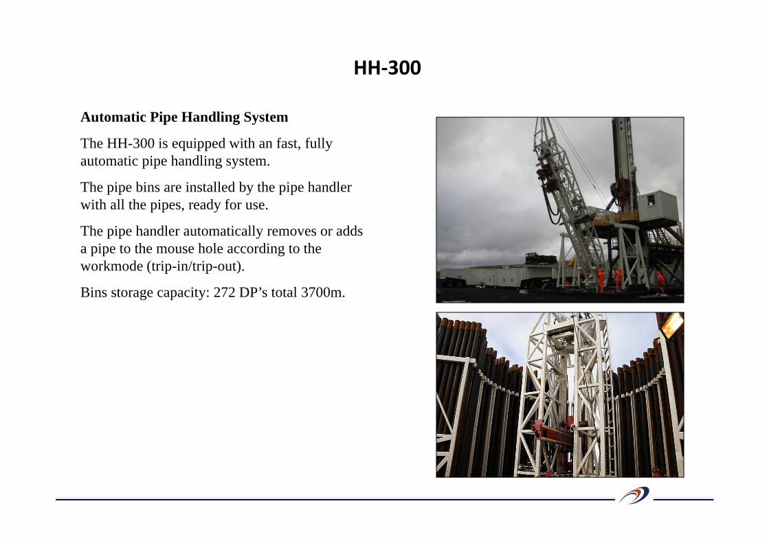
Automatic Pipe Handling System
The HH-300 is equipped with an fast, fully automatic pipe handling system.
The pipe bins are installed by the pipe handler with all the pipes, ready for use.
The pipe handler automatically removes or adds a pipe to the mouse hole according to the workmode (trip-in/trip-out).
Bins storage capacity: 272 DP’s total 3700m.
HH‐300
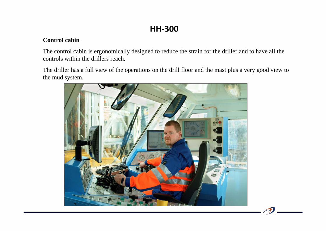
Control cabin
The control cabin is ergonomically designed to reduce the strain for the driller and to have all the controls within the drillers reach.
The driller has a full view of the operations on the drill floor and the mast plus a very good view to the mud system.
HH‐300
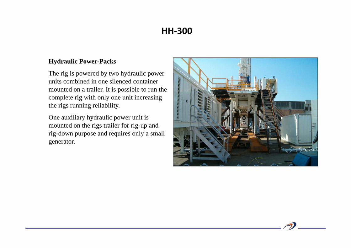
Hydraulic Power-Packs
The rig is powered by two hydraulic power units combined in one silenced container mounted on a trailer. It is possible to run the complete rig with only one unit increasing the rigs running reliability.
One auxiliary hydraulic power unit is mounted on the rigs trailer for rig-up and rig-down purpose and requires only a small generator.
HH‐300

Three Drillmec 9T 1000 mud pumps.
Each pump is a triplex single acting 1000 hp pump electrically driven.
Capacity, each pump:
Max volume:
37 l/sec @ 185 bar
32 l/sec @ 215 bar
27 l/sec @ 253 bar
23 l/sec @ 300 bar
19 l/sec @ 350 bar
Max pressure: 350 bar
Mud system:
HH‐300
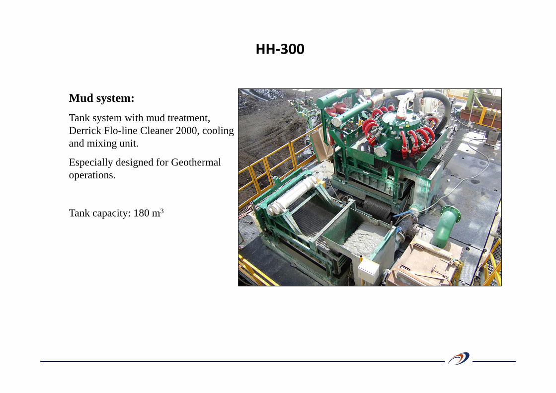
Mud system:
Tank system with mud treatment, Derrick Flo-line Cleaner 2000, cooling and mixing unit.
Especially designed for Geothermal operations.
Tank capacity: 180 m3
HH‐300
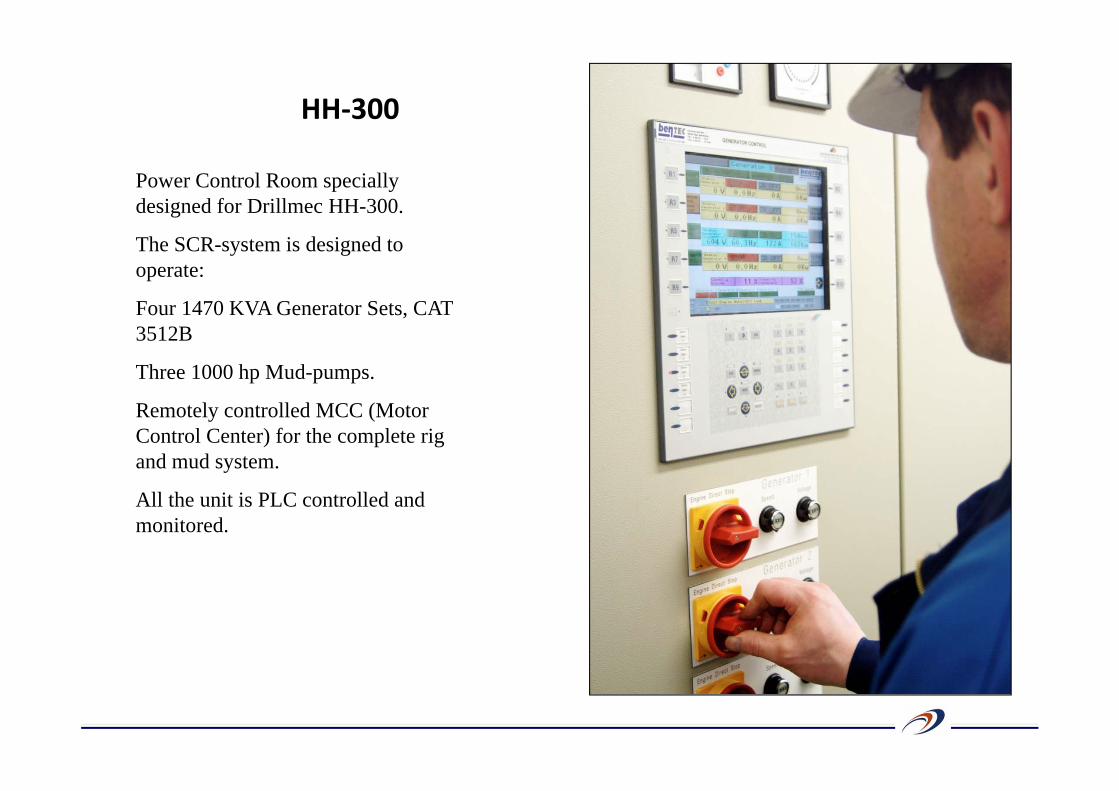
Power Control Room specially designed for Drillmec HH-300.
The SCR-system is designed to operate:
Four 1470 KVA Generator Sets, CAT 3512B
Three 1000 hp Mud-pumps.
Remotely controlled MCC (Motor Control Center) for the complete rig and mud system.
All the unit is PLC controlled and monitored.
HH‐300
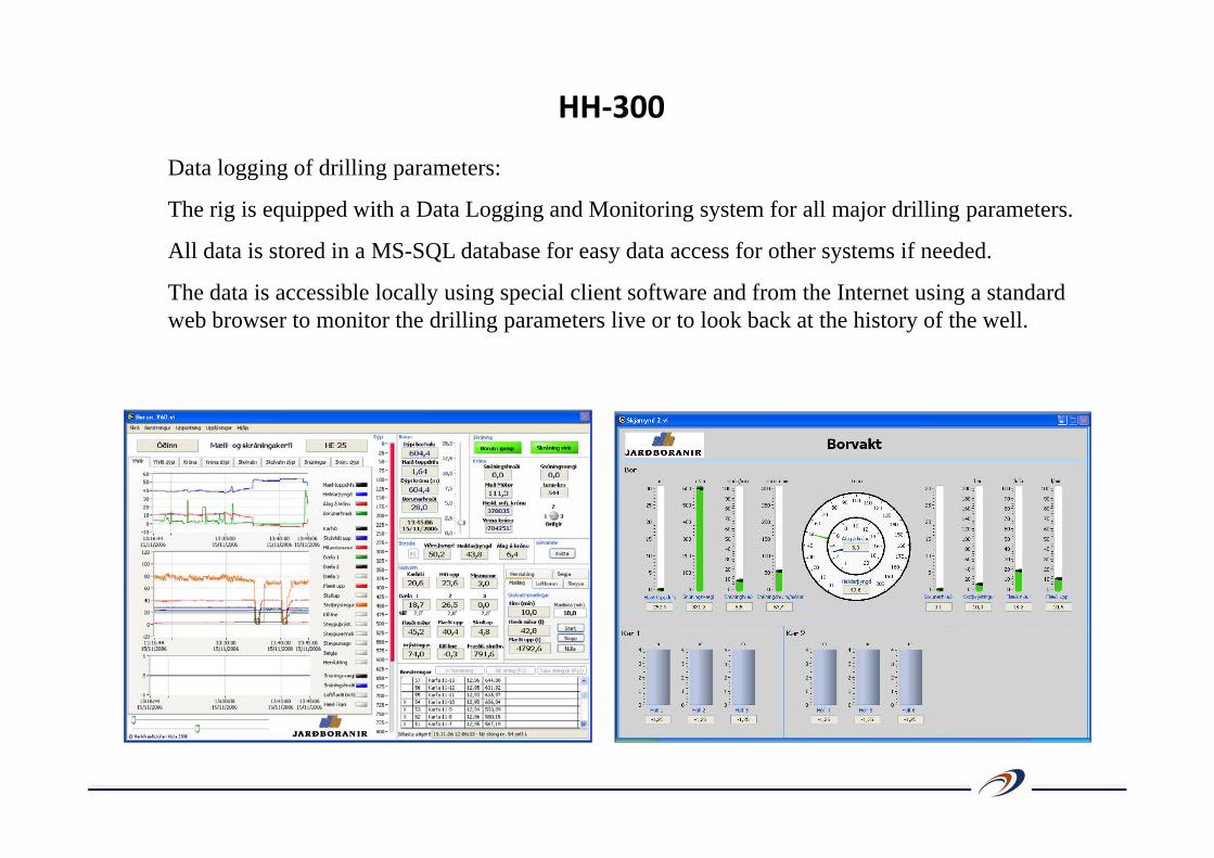
Data logging of drilling parameters:
The rig is equipped with a Data Logging and Monitoring system for all major drilling parameters.
All data is stored in a MS-SQL database for easy data access for other systems if needed.
The data is accessible locally using special client software and from the Internet using a standard web browser to monitor the drilling parameters live or to look back at the history of the well.
HH‐300
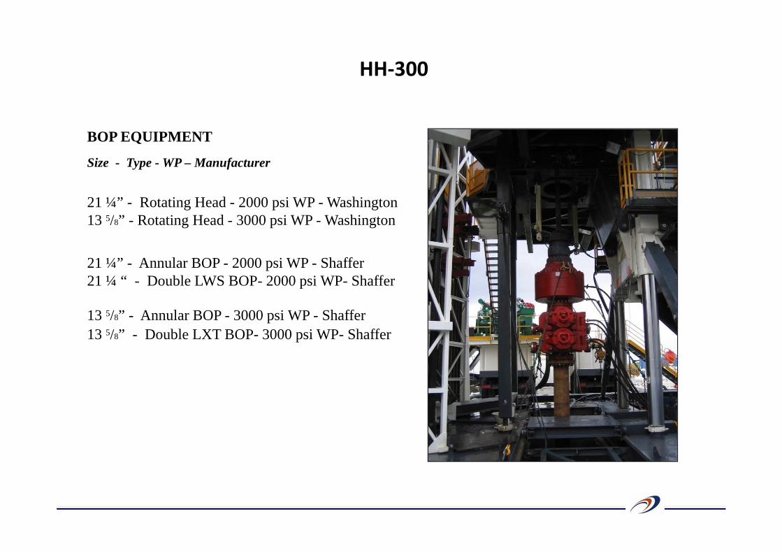
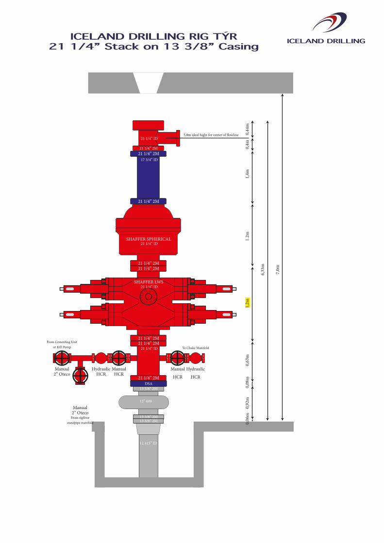
BOP EQUIPMENT
Size - Type - WP – Manufacturer
21 ¼” - Rotating Head - 2000 psi WP - Washington13 5/8” - Rotating Head - 3000 psi WP - Washington
21 ¼” - Annular BOP - 2000 psi WP - Shaffer21 ¼ “ - Double LWS BOP- 2000 psi WP- Shaffer
13 5/8” - Annular BOP - 3000 psi WP - Shaffer13 5/8” - Double LXT BOP- 3000 psi WP- Shaffer
HH‐300
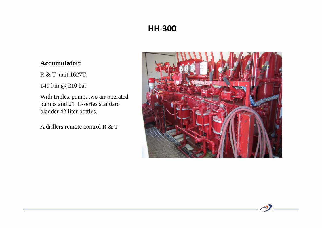
Accumulator:
R & T unit 1627T.
140 l/m @ 210 bar.
With triplex pump, two air operated pumps and 21 E-series standard bladder 42 liter bottles.
A drillers remote control R & T
HH‐300
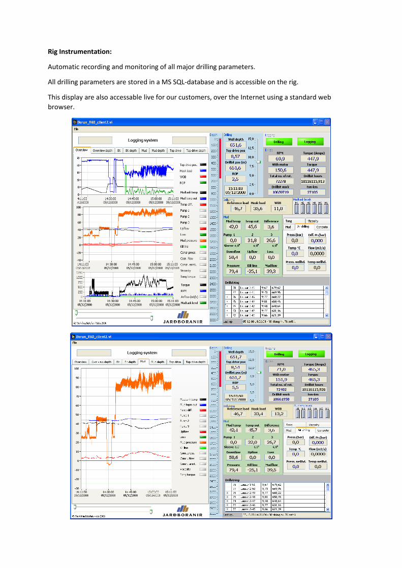
Rig Instrumentation:
Automatic recording and monitoring of all major drilling parameters.
All drilling parameters are stored in a MS SQL-database and is accessible on the rig.
This display are also accessable live for our customers, over the Internet using a standard web browser.
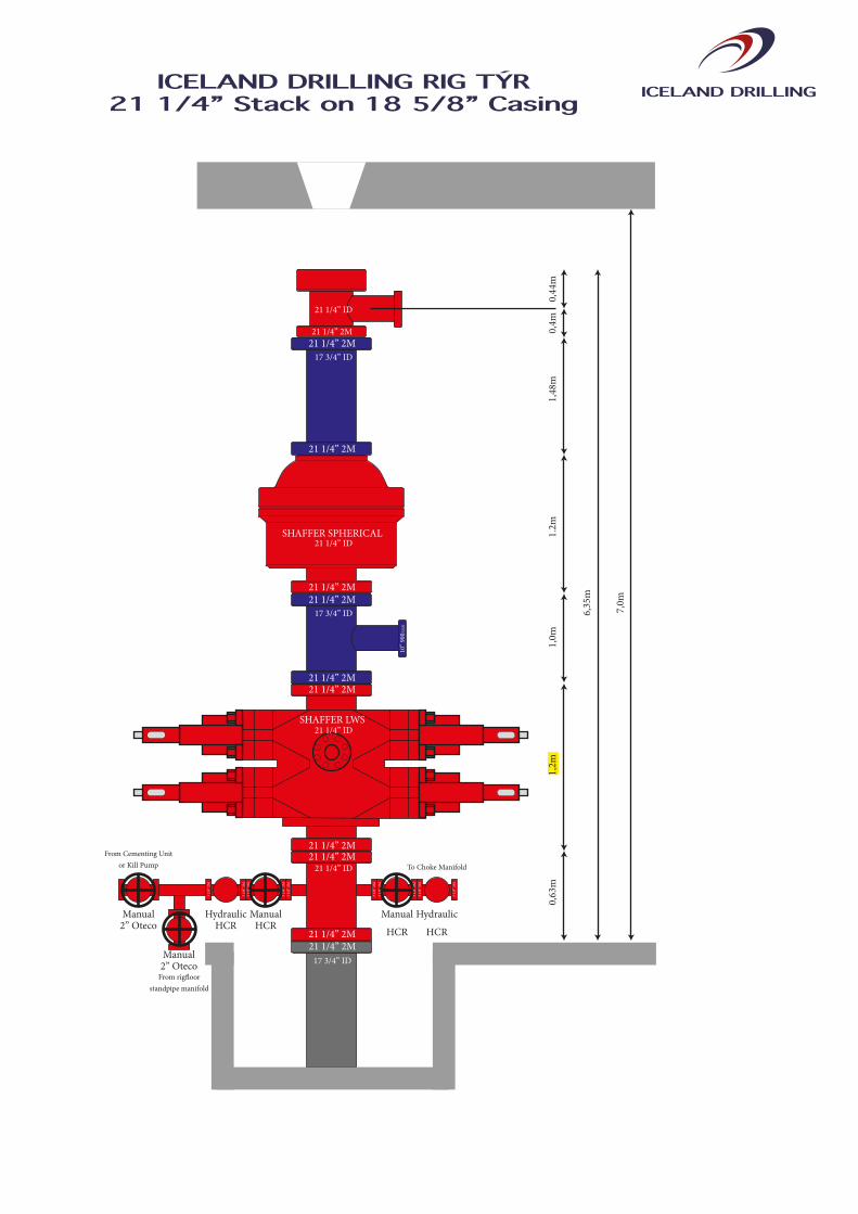
21 1/4” 2M
SHAFFER SPHERICAL
SHAFFER LWS
21 1/4” 2M
10” 9
00A
NSI
21 1/4” 2M
Manual
HCR
ManualHCR
HydraulicHCR
Manual2” Oteco
Manual2” Oteco
From rig�oorstandpipe manifold
From Cementing Unitor Kill Pump To Choke Manifold
Hydraulic
HCR
0,63
m
6,35
m
1,0m
0,4m
1.2m
0,44
m1,
2m1,
48m
21 1/4” 2M
21 1/4” ID
21 1/4” ID
21 1/4” ID
17 3/4” ID
21 1/4” 2M
21 1/4” 2M
17 3/4” ID
21 1/4” 2M
21 1/4” 2M21 1/4” 2M
3 1/
8” 2
M3
1/8”
2M
3 1/
8” 2
M3
1/8”
2M
3 1/
8” 2
M3
1/8”
2M
3 1/
8” 2
M
3 1/
8” 2
M3
1/8”
2M
3 1/
8” 2
M
21 1/4” 2M
17 3/4” ID21 1/4” 2M
7,0m
21 1/4” ID
ICELAND DRILLINGICELAND DRILLING RIG TÝR21 1/4” Stack on 18 5/8” Casing
21 1/4” 2M
SHAFFER SPHERICAL
SHAFFER LWS
Manual
HCR
ManualHCR
HydraulicHCR
Manual2” Oteco
Manual2” Oteco
From rig�oorstandpipe manifold
From Cementing Unitor Kill Pump To Choke Manifold
Hydraulic
HCR
0,63
m
6,33
m
0,4m
1.2m
0,44
m1,
2m1,
4m
5,8m ideal hight for center of �owline
21 1/4” 2M
21 1/4” ID
21 1/4” ID
21 1/4” ID
21 1/4” 2M
21 1/4” 2M
17 3/4” ID
21 1/4” 2M
21 1/4” 2M21 1/4” 2M
3 1/
8” 2
M3
1/8”
2M
3 1/
8” 2
M3
1/8”
2M
3 1/
8” 2
M3
1/8”
2M
3 1/
8” 2
M
3 1/
8” 2
M3
1/8”
2M
3 1/
8” 2
M
21 1/4” 2M
12.415” ID
13 3/8” 2M13 3/8” 2M
13 3/8” 2MDSA
0,92
m0,
06m
0,08
m
7,0m
21 1/4” ID
12” 600
ICELAND DRILLINGICELAND DRILLING RIG TÝR21 1/4” Stack on 13 3/8” Casing
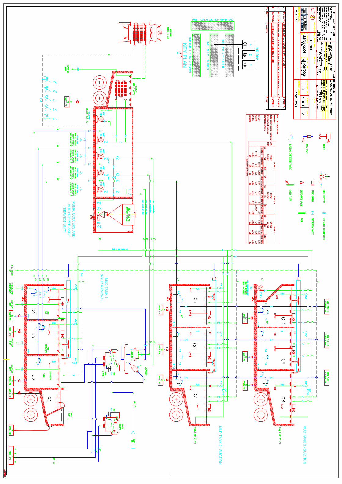
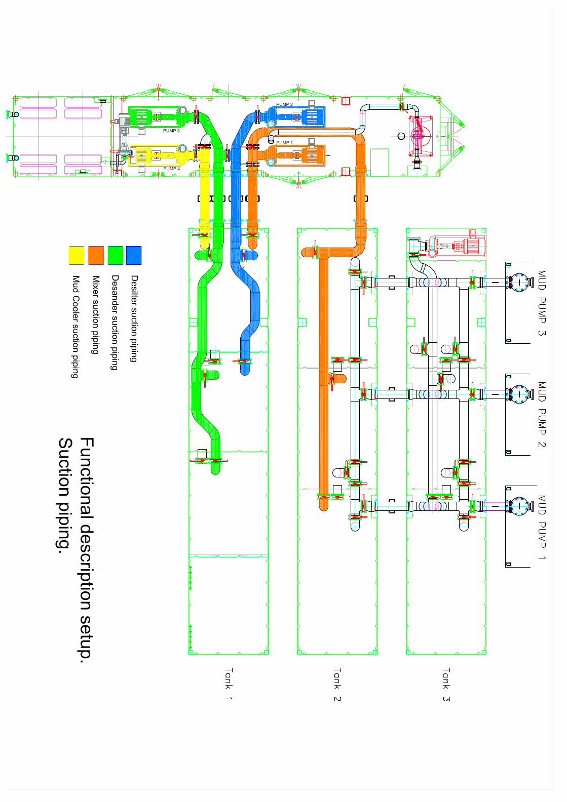
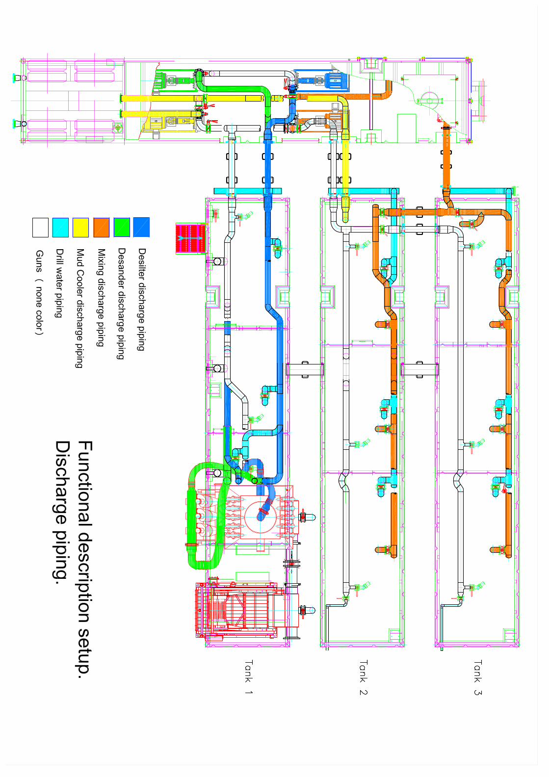
Mud System
Rigs standard mud tank system (See attached drawing)
Please keep in mind that the drawing is only showing 2 shale shakers. The third shaker has been
added and can be seen on the overview picture.
TOTAL OF 4 MOBILE UNITS. (Within EU transport regulation). 3 mudtanks and 1 unit with mud
hopper and big sack silo. Capacity of standard tank system is 180 M3 with 9 compartments and 1
sandtrap.
Ability to draw from 4 compartmented tanks when mixing (orange pipe in drawing 1). Direct treated
mud from the hopper discharge to 7 compartmented tanks. Paddle agitators are in 7 compartments.
Sub surface gun lines in 9 compartments.
Tank 1. is the sandtrap. Mud flows from shale shaker into compartment 1. From compartment 1 the
mud is picked up by a centrifugal pump (green) that is located in the mud mixing unit and pumped
through the Desander and into compartment nr. 2. From there it is picked up by another centrifugal
pump (blue) and pumped through the Desilter and into compartment nr. 3.
Mud is then ready to be mixed from compartments 3,4,5 and 6 with new mixed mud from the
whopper. The mud is then discharged (orange pipe in drawing 2) from the whopper to compartments
4,5,6,7,8 and 9.
Mud pumps can suck from compartments 4,5,6,7,8 and 9 and from this compartments the mud is
pumped into the well.
See further volume of these tanks on the standard mud diagram.
Mud cooler. When using the mud cooler mud is picked up from compartment 3 and from the cooler
the mud returns to compartments 3 or 6.
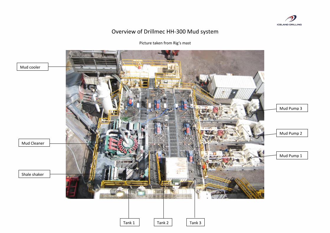
Overview of Drillmec HH-300 Mud system
Picture taken from Rig‘s mast
Mud Pump 1
Mud Pump 2
Mud Pump 3
Tank 1 Tank 3 Tank 2
Shale shaker
Mud Cleaner
Mud cooler
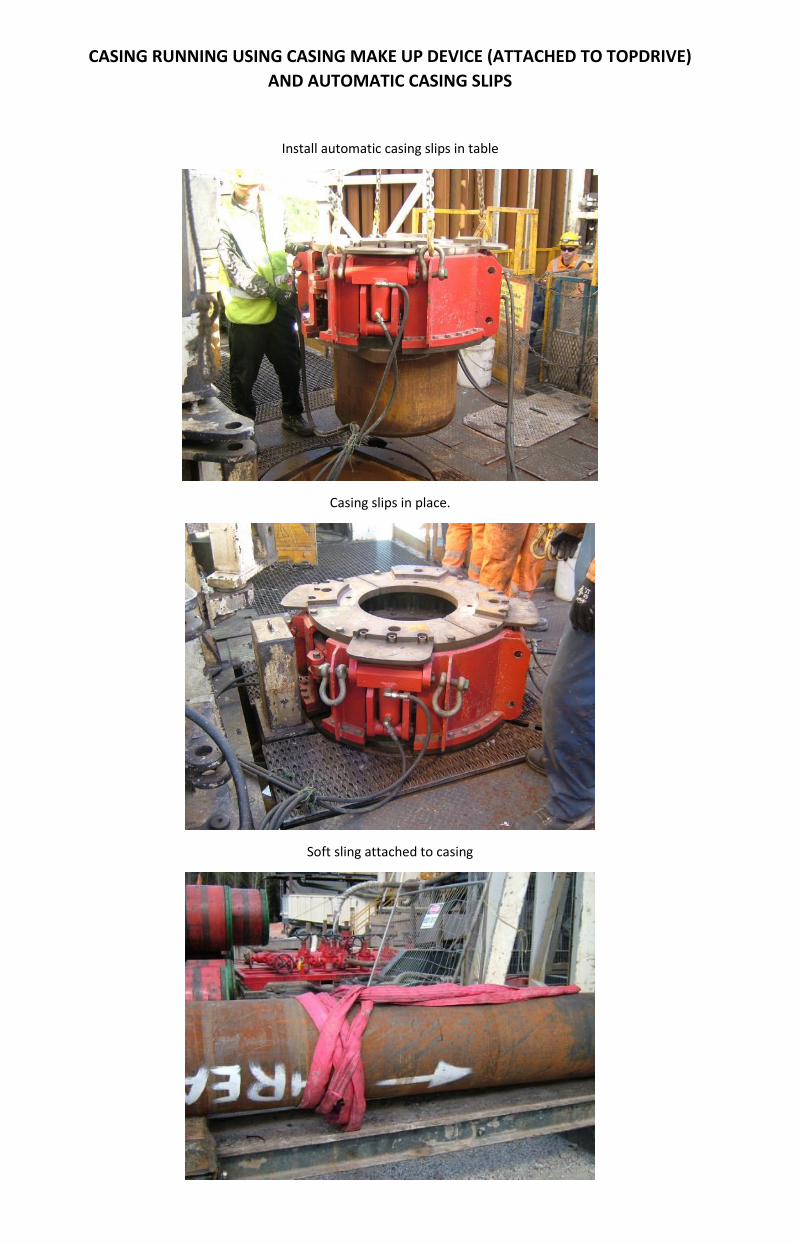
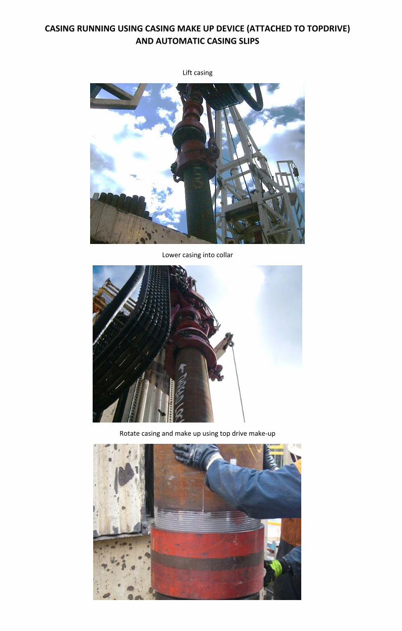
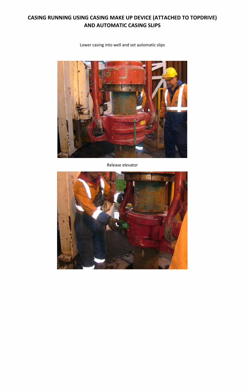
CASING RUNNING USING CASING MAKE UP DEVICE (ATTACHED TO TOPDRIVE)
AND AUTOMATIC CASING SLIPS
Install automatic casing slips in table
Casing slips in place.
Soft sling attached to casing
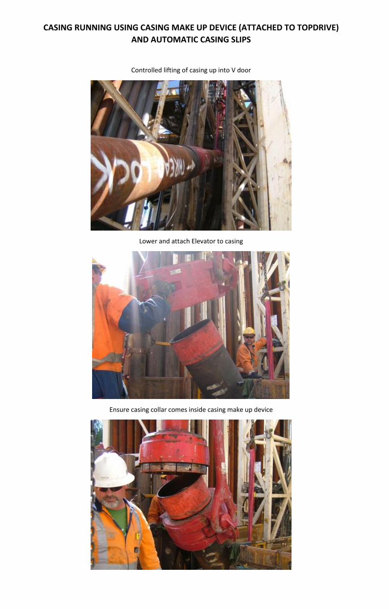
CASING RUNNING USING CASING MAKE UP DEVICE (ATTACHED TO TOPDRIVE)
AND AUTOMATIC CASING SLIPS
Controlled lifting of casing up into V door
Lower and attach Elevator to casing
Ensure casing collar comes inside casing make up device
CASING RUNNING USING CASING MAKE UP DEVICE (ATTACHED TO TOPDRIVE)
AND AUTOMATIC CASING SLIPS
Lift casing
Lower casing into collar
Rotate casing and make up using top drive make-up
CASING RUNNING USING CASING MAKE UP DEVICE (ATTACHED TO TOPDRIVE)
AND AUTOMATIC CASING SLIPS
Lower casing into well and set automatic slips
Release elevator