Embed Size (px)
Citation preview
D R I L L I N G & C O M P L E T I O N
Bottom line benefits justify deepwater IWS
Stefano di VincenzoEni E&P
Michele ArenaSchlumberger
Deepwater development presents many challenges, from drilling to comple-tion to production. This is the story of an extremely complex set of challeng-es that were addressed successfully
offshore Nigeria, returning significant bene-fits to the operator in the form of an increase in net present value of 15% and an increase in overall reservoir recovery factor of 6%.
Setting the sceneAbout 37 miles (60 km) offshore Nigeria,
in about 2,132 ft (650 m) of water, several tur-bidite sand lobes located at different levels constitute a high-permeability reservoir with numerous mud-filled channels providing po-tential isolating barriers. The reservoir con-sists of a northern lobe and a southern lobe, subdivided in three levels, A, B, and C. A total of eight wells were drilled initially, all target-ing level A. Wells 1, 2, 3, 5 and 6 terminated in the northern lobe and wells 4 and 7 termi-nated in the southern lobe. In 2005, an eighth well was drilled that, while targeting level A, also penetrated levels B and C, confirming the complex nature of the reservoir and call-ing for a reassessment of completion options.
The team was faced with several challeng-es, both technical and legal. Under Nigerian law, each zone in a multi-zone completion must be isolated and monitored. On the tech-nical side, sand management and crossflow were the major issues.
After appropriate engineering study, the following objectives and challenges were identified:
• Well control—three fully separated, moni-tored and controlled zones were to be de-ployed in a single completion run.
• Equipment clearance—very tight clear-ances between upper and lower comple-tion units and between tubulars were expected.
• Zonal allocation—Downhole zonal al-location must comply with Nigerian law.
• Zonal isolation—high integrity isolation was required for selective isolation and control.
• Well position—water depth required a dynamically positioned rig.
The first step was to see if a single-well in-telligent well systems (IWS) completion was technically possible, given the constraints posed by the reservoir conditions, the dimen-sions of available completion equipment and compliance with the law. If the first step was deemed to be feasible, the second step would compare different alternatives to evaluate economics.
Attention to detail facilitates decision
During the evaluation phase, and before the final completion decision was taken, the team was faced with a complex set of eco-nomic and technical alternatives. Initially, the plan was to consider only existing technolo-gies applied to three single-zone horizontal open hole gravel pack completions and dual-zone cased hole gravel pack completions. As third option there was the new technologies applied to a single deviated well completed with triple IWS and frac pack for sand man-agement. The well would produce com-mingled from all three isolated levels, with precise downhole monitoring of each level to comply with Nigerian law.
After some study, the Base Case was re-moved from consideration because of prob-lems experienced in previous wells with open hole gravel pack completions. Thus, alterna-tives 1 and 2 were all that remained. To make the project profitable in the long term, a gas injector completion was added. Accordingly, the final decision was between the following alternative scenarios:
Alternative No. 1 (four wells)• One single producer (level B)• One dual zone producer with IWS (levels
A and C)
• One dual zone producer with IWS (levels A and B)
• One triple zone gas injector (levels A, B, and C commingled).
Alternative No. 2 (three wells)• One triple zone producer with IWS (lev-
els A, B, and C)• One dual zone producer with IWS (levels
A and B)• One triple zone gas injector with IWS
(levels A, B, and C commingled).
First step – Completion design feasibility
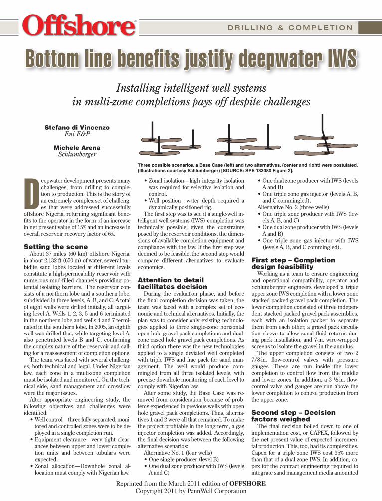
Working as a team to ensure engineering and operational compatibility, operator and Schlumberger engineers developed a triple upper zone IWS completion with a lower zone stacked packed gravel pack completion. The lower completion consisted of three indepen-dent stacked packed gravel pack assemblies, each with an isolation packer to separate them from each other, a gravel pack circula-tion sleeve to allow zonal fluid returns dur-ing pack installation, and 7-in. wire-wrapped screens to isolate the gravel in the annulus.
The upper completion consists of two 2 7/8-in. flow-control valves with pressure gauges. These are run inside the lower completion to control flow from the middle and lower zones. In addition, a 3 ½-in. flow-control valve and gauges are run above the lower completion to control production from the upper zone.
Second step – Decision factors weighed
The final decision boiled down to one of implementation cost, or CAPEX, followed by the net present value of expected incremen-tal production. This, too, had its complexities. Capex for a triple zone IWS cost 35% more than that of a dual zone IWS. In addition, ca-pex for the contract engineering required to integrate sand management media amounted
Three possible scenarios, a Base Case (left) and two alternatives, (center and right) were postulated. (Illustrations courtesy Schlumberger) [SOURCE: SPE 133080 Figure 2].
Installing intelligent well systems in multi-zone completions pays off despite challenges
Reprinted from the March 2011 edition of OFFSHORECopyright 2011 by PennWell Corporation

Safety valve
9 5/8” Gravel pack packerGravel pack assembly
7” Wire wrapped screens
9 5/8” Gravel pack packerGravel pack assembly
7” Wire wrapped screens
9 5/8” Gravel pack packer
Gravel pack assembly
7” Wire wrapped screens
9 5/8” Production packer
3 1/2” Row control valve
Blast joint
6” Multi-ported seal assembly
2 7/8” Down hole gauges2 7/8” Flow control valve
Blast joint
6” Multi-ported seal assembly
2 7/8” Down hole gauges2 7/8” Flow control valve
7” wire wrapped screensfor Sand Control assembly
2_’ �ow control valves-multistep fully hydraulic
Cement and formationbehind perforations
Clearance CSG/Screens = 0.7625”
Electrical cable
9.625” productioncasingID drift - 8.525”
Flat pack for Intelligent Completion
D R I L L I N G & C O M P L E T I O N
to a 15% increase. Finally, well capex required to install the triple zone completion added 23% to the overall cost.
On the other hand, expected incremental production for the triple zone completion versus the dual zone completion was more than 1 MMbbl.
When the total field development solution was taken into account, alternative No. 2 offered some very attractive ben-efits. Drilling one less well would save about $24 million. A complete subsea facility equipment and installation cost for one well would be saved. Production from level C would be controlled with concurrent ability to exercise conformance and depletion control. It should be noted that these benefits assumed the IWS would perform reliably.
The main advantages of the option chosen are as follow:• Reduced capex—One well to drill and complete, versus
the other options.• Increased production—Additional production was expect-
ed due to gas lifting from level A helping to lift production from levels B and C.
• Zonal control—Provides the ability to react to premature water breakthrough or early depletion of a zone.
Alternative 2 implementation Seven-inch sand screens were selected over 6 5/8-in.
screens despite the fact that clearance between the 9 5/8-in. casing and the screens was less than 1 in. This was because the added strength of the larger screens was deemed signifi-cant during run-in and later when the well was put on produc-tion.
All flow-control valves were checked to ensure their oper-ating range accommodated the expected production profiles for each valve aperture position and achieved optimum draw-down.
A 6-in. multi-ported bonded seal assembly isolated the two lower zones while allowing passage of hydraulic and electrical
control and telemetry lines for the flow-control valve and gauges. To protect the control lines, grooved blast joints were positioned oppo-site each perforated interval. These featured self-aligning connections that aligned the grooves within 0.01-in. (0.25 mm) when the connec-tions were made up so the lines were protected across several joints.
Radial clearance between flow-control valves and the sand screens was 0.851-in. considered sufficient to prevent damage to the control lines and prevent swabbing during upper completion run-in. This also allowed circulation during stab-in.
Flow path through the completion shows how each zone’s produc-tion makes its way through the completion. Each zone’s contribution is controlled and monitored using the IWS control-valves and gauges before it is commingled for its ultimate journey to the surface produc-tion facility.
To ensure long-term reliability, engineers were careful to avoid placing flow-control valves opposite perforations. This affected completion equipment length for each zone, which was 15-ft (4.5 m) for level A, 43-ft (13 m) for level B and 34-ft (10.5 m) for level C. The interval distance between layers was 102-ft (31 m) between the bottom of level A and the top of level B, and 105-ft (32 m) from the bottom of level B to the top of level C. The well’s maximum deviation of 32.5° with a maxi-mum dogleg severity of 3.1°/100-ft was considered adequate to avoid problems during run-in or gravel packing operations, or subsequently during the life of the reservoir.
Results exceed expectationsPlanned versus actual costs for alternative No. 2 were en-
couraging. For the well drilled with the triple IWS completion and the well drilled with the dual IWS completion, IWS mate-rial capex came in as planned at 35%; IWS service capex was less than 12.5% versus the plan of 15%; and the overall well ca-pex difference was reduced to less than 6% against the planned 23%.
On the production side, cumulative oil produced reached normally expected levels seven months ahead of time and six months ahead of the most optimistic expectations. The AFE was re-paid within 15 months of production; net present value of the well increased by 15% and reservoir recovery factor was calculated to have risen from 24.7% to 31.05%. •
A triple upper zone IWS completion (left) and a stacked packed gravel pack lower zone comple-tion (right) were designed. [SOURCE: SPE 133080 Figure 1].
Radial clearances, while tight, were adequate to allow effective distribution of the gravel pack while ensuring sufficient clearance for control lines. [SOURCE: SPE 133080 Figure 7].
Flow diagram illustrates how each zone flows through the completion to its ultimate commingling at the top. [SOURCE: SPE 133080 Figure 8].