Embed Size (px)
Citation preview

Originally published as:
Prevedel, B., Martens, S., Norden, B., Henninges, J., Freifeld, B. M. (2014): Drilling and Abandonment Preparation of CO2 storage wells – Experience from the Ketzin pilot site. - Energy Procedia, 63, p. 6067-6078.
DOI: http://doi.org/10.1016/j.egypro.2014.11.639
Energy Procedia 63 ( 2014 ) 6067 – 6078
Available online at www.sciencedirect.com
ScienceDirect
1876-6102 © 2014 The Authors. Published by Elsevier Ltd. This is an open access article under the CC BY-NC-ND license (http://creativecommons.org/licenses/by-nc-nd/3.0/).Peer-review under responsibility of the Organizing Committee of GHGT-12doi: 10.1016/j.egypro.2014.11.639
GHGT-12
Drilling and abandonment preparation of CO2 storage wells –
Experience from the Ketzin pilot site Bernhard Prevedela*, Sonja Martensa, Ben Nordena, Jan Henningesa, Barry M. Freifeldb
aGFZ German Centre for Geoscience, Telegrafenberg, 14473 Potsdam, Germany bLawrence Berkeley National Lab, Cyclotron Road, Berkeley, CA 94720, U.S.A.
Abstract
At Ketzin, located west of Berlin, the GFZ German Centre for Geosciences is operating Europe's largest CO2 research storage site. This pilot site has been developed since 2004 and is comprised of one combined injection/observation well and four monitoring wells. From June 2008 to August 2013, a total of 67 kilotons of CO2 were safely injected into the sandstone units of the Upper Triassic Stuttgart Formation in a depth between 630 to 650 m. The paper discusses the well designs and lessons learned in drilling engineering and operations. The abandonment phase started in Ketzin with the first plug cementation of the observation well Ktzi 202 shortly after shut-in of CO2 injection. The experience with the first CO2 well killing operation will be reviewed. © 2013 The Authors. Published by Elsevier Ltd. Selection and peer-review under responsibility of GHGT.
Keywords: Well design; Permanent down-hole monitoring; Mud losses; Cementation; Perforation; Abandonment; Well killing
1. Introduction
Saline aquifers are regarded as one of the most promising storage solution for Carbon Capture and Storage (CCS) projects [1]. The Ketzin pilot site in Germany is an example of saline storage and represents the first European on-shore project on research of geological CO2 storage [2-5]. Pilot sites like Ketzin form an essential part of a roadmap towards the implementation of CO2 storage on an industrial scale as they allow performing field experiments and the
* Corresponding author. Tel.: +49-331-288-1080; fax: +49-331-2881088. E-mail address: [email protected]
© 2014 The Authors. Published by Elsevier Ltd. This is an open access article under the CC BY-NC-ND license (http://creativecommons.org/licenses/by-nc-nd/3.0/).Peer-review under responsibility of the Organizing Committee of GHGT-12

6068 Bernhard Prevedel et al. / Energy Procedia 63 ( 2014 ) 6067 – 6078
testing of different technological and operational strategies that may be difficult to realize at larger demonstration or industrial scales [6, 7].
The Ketzin pilot site is located in a rural area about 25 km west of Berlin in the Northeast German Basin (NEGB). The project commenced in 2004 with the baseline characterization [8] and preparatory work in advance of the CO2 injection. From June 2008 to August 2013, a total of 67 kilotons of CO2 were safely injected into the sandstone units of the Upper Triassic Stuttgart Formation in a depth between 630 to 650 m. CO2 storage at Ketzin is accompanied by one of the most comprehensive research and development (R&D) programs worldwide, with key objectives focusing on drilling and well completion, injection operation, monitoring, and modelling. The recovery of cores is another fundamental part of the project allowing the characterization and comparison of reservoir rocks and cap rock material at different project phases, e.g. before and during CO2 injection. Furthermore, the boreholes supplied the infrastructure for injection and extensive operational and scientific monitoring. As an R&D driven project, a dense infrastructure including five boreholes with a maximum distance of 112 m to each other was realized. These boreholes were drilled in three campaigns between 2007 and 2012: March to September 2007: Prior to the start of CO2 injection the three boreholes CO2 Ktzi 200/2007
(abbreviated as Ktzi 200), CO2 Ktzi 201/2007 (Ktzi 201) and CO2 Ktzi 202/2007 (Ktzi 202) were drilled to a depth of about 750 m to 800 m [9]. One of these wells (Ktzi 201) was used as a combined injection and observation well while the other two serve as observations wells.
June to August 2011: The shallow observation well Hy Ktzi P300/2011 (P300), a borehole to the first sandstone
layers above the CO2 storage cap rock was drilled in order to continuously monitor the integrity of the storage and to trace fluctuations of natural geogenic CO2 outside the storage reservoir.
August and September 2012: The research infrastructure was completed with the drilling of the last observation
well CO2 Ktzi 203/2012 (Ktzi 203) close to the injection point to gain rock cores from the cap rock and reservoir, which was in contact with the injected CO2 for more than four years.
In this publication we present and discuss the well designs, the procedures and challenges in drilling engineering and operations. As abandonment of one observation well started shortly after cessation of CO2 injection, the well killing operation is also reviewed. With regard to the permanent downhole monitoring installations, we focus in this contribution on DTS. For additional information on the operational pressure and temperature (P/T) monitoring, the hydraulic monitoring of the above-zone and the geoelectrical monitoring using the VERA system the reader is kindly referred to the publications [6, 10, 11].
2. Geological background
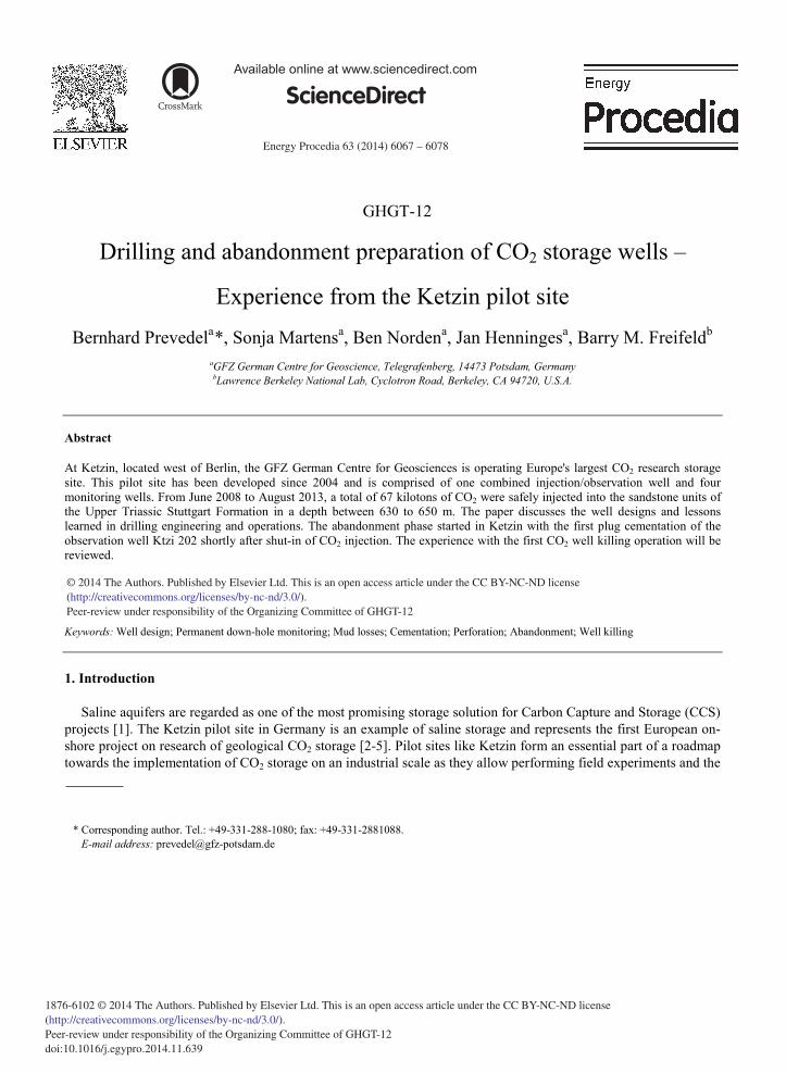
The Ketzin pilot site for CO2 storage was developed at an anticlinal structural setting of the NEBG. The site is located on the eastern part of a double anticlinal structure, the Roskow-Ketzin anticline (Fig. 1). Although the general geological setting was well known from the commercial storage of town and natural gas conducted in the past at a shallower depth interval, a high uncertainty existed about the actual lithological composition and the reservoir quality of the intended CO2 storage formation, the Triassic Stuttgart Formation [8]. Therefore, the first wells drilled within the Ketzin project in 2007 (Ktzi 200, Ktzi 201, Ktzi 202) acted as exploration wells at the same time [12]. The geological objectives of these drillings consisted of the geological and petrophysical characterization of the Stuttgart Formation and the overburden, the identification of a reservoir section suitable for CO2 storage, and the recovering of drill cores from the target zone (reservoir and immediate cap rock).
Bernhard Prevedel et al. / Energy Procedia 63 ( 2014 ) 6067 – 6078 6069
Fig. 1. Location of the Ketzin pilot site and lithological variation of the CO2 storage target formation (Stuttgart Formation). The black star denotes the Ketzin pilot site, where P300, Ktzi 200, Ktzi 201, Ktzi 202, and Ktzi 203 were drilled as vertical wells (magnification panel in upper-left corner). Note also from the litho-panels the scattered location of the Stuttgart Formation (yellow) due to a faulting character in the western part of the anticline structure as well as the absence of rock salt in the eastern part.
3. Drilling and completion
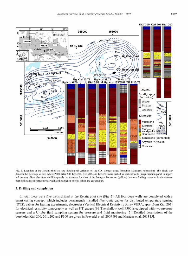
In total there were five wells drilled at the Ketzin pilot site (Fig. 2). All four deep wells are completed with a smart casing concept, which includes permanently installed fiber-optic cables for distributed temperature sensing (DTS), cables for heating experiments, electrodes (Vertical Electrical Resistivity Array VERA; apart from Ktzi 203) for electrical resistivity tomography as well as P/T gauges [9]. The shallow well P300 is equipped with two pressure sensors and a U-tube fluid sampling system for pressure and fluid monitoring [5]. Detailed descriptions of the boreholes Ktzi 200, 201, 202 and P300 are given in Prevedel et al. 2009 [9] and Martens et al. 2013 [5].
6070 Bernhard Prevedel et al. / Energy Procedia 63 ( 2014 ) 6067 – 6078
A special status remains for the shallow P300 monitoring well where for the first and only time at Ketzin, a counter-flush airlift drilling was employed for the uppermost drilling section until a depth of 153 m. This drilling technology assured excellent borehole stability, especially in the Tertiary clay formation, but turned out on the other hand to be very time consuming and with clearly reduced drilling performance. It was therefore found not to be competitive with classic rotary drilling techniques.
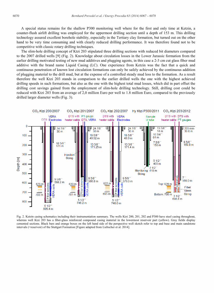
The slim-hole drilling concept of Ktzi 203 stipulated three drilling sections with reduced bit diameters compared to the 2007 drilled wells [9] (Fig. 2). Knowledge about circulation losses in the Lower Jurassic formation from the earlier drilling motivated testing of new mud additives and plugging agents, in this case a 2-3 cm cut glass fiber mud additive with the brand name Liquid Casing (LC). One experience from Ketzin was the fact that a quick and continuous penetration of known lost circulation formations can only be safely achieved by the continuous addition of plugging material to the drill mud, but at the expense of a controlled steady mud loss to the formation. As a result therefore the well Ktzi 203 stands in comparison to the earlier drilled wells the one with the highest achieved drilling speeds in such formations, but also as the one with the highest total mud losses, which did in part offset the drilling cost savings gained from the employment of slim-hole drilling technology. Still, drilling cost could be reduced with Ktzi 203 from an average of 2,0 million Euro per well to 1.8 million Euro, compared to the previously drilled larger diameter wells (Fig. 3).
Fig. 2. Ketzin casing schematics including their instrumentation summary. The wells Ktzi 200, 201, 202 and P300 have steel casing throughout, whereas well Ktzi 203 has a fiber-glass reinforced compound casing material in the lowermost reservoir part (yellow). Gray fields display cemented sections. Black bars and orange boxes on the left hand side of the perspective well sketch refer to top and base and main sandstone intervals (=reservoir) of the Stuttgart Formation [Figure adapted from Liebscher et al. 2014].
Bernhard Prevedel et al. / Energy Procedia 63 ( 2014 ) 6067 – 6078 6071
Fig. 3. Drilling performance (columns) and drilling cost (line) of same depth injection and monitoring wells at the Ketzin pilot site. The columns represent the drilling days required to arrive with the drill bit at a certain casing setting depth up to the individual planned end depth of each borehole with the cementation of its last casing string. The drilling cost line (right ordinate) includes the cost for drilling of the four deep wells from site construction to the entire well construction expenditures starting with mobilization until de-mobilization of the drill rig from location.
4. DTS permanent downhole monitoring
For reasons of avoiding the risk of damages to the permanent downhole sensor arrays from casing perforation, the earlier Ketzin wells from 2007 were completed with long non cemented casing sections across the storage horizon and with pre-installed filter screens, for which a two-stage cementation program had to be performed [9]. This well completion setup proved to result in unfavorable conditions for geophysical monitoring, because of invasion of CO2 into the non cemented annuli above the filter sections [13]. The Ktzi 203 well design was for that reason changed and included a fully cemented casing section across the injection interval and was equipped with two redundant permanent down-hole sensor cables for distributed temperature sensing and heat pulse measurements [14]. In comparison to the previous installations at Ketzin, the number of downhole cables could be reduced by using a single combined sensor cable, containing optical fibers for DTS and electrical conductors for heating. After the sensor cables had been installed the cementing of the 3.5” casing was monitored with DTS. Fluid circulation and cement placement was clearly visible during two phases with reduced temperatures. Afterwards, temperatures again recovered towards the geothermal profile, with an additional increase in the temperature in the lower part of the borehole due to the heat released during setting of the cement. From the DTS data, the top-of-cement (TOC) could be detected at approximately 330 m depth, some 30 m higher than planned, which corresponds very well with the results of the subsequent recorded cement bond log.
The DTS data indicated that fluid circulation during cementing generally proceeded as planned, but it was noted that the TOC was at a somewhat shallower depth than expected and the relatively low temperature increase during hydration indicated a possible dilution of the cement. During wire-line logging a blockage inside the cemented 3.5” casings was subsequently observed at approximately 577 m, some 112 m above the cementing float collars. A

6072 Bernhard Prevedel et al. / Energy Procedia 63 ( 2014 ) 6067 – 6078
dedicated evaluation of heat-pulse measurements revealed that a change of the thermal properties of the near-well zone was occurring at the depth of the blockage of the well (Fig. 4).
Fig. 4. Results of heat-pulse measurements in well Ktzi 203. 1st panel: Temperature changes directly after cement displacement. TC: thermal conductivities calculated using numerical inversion (2nd panel), and analytical approaches for early- (3rd panel) and late-time data (4th panel), representative for the near- and far field around the well, respectively. The section where solid cement was retrieved from below the obstruction is indicated in blue in the well sketch on the left. Far-field TC-logs clearly indicate the K2-Anhydrite marker horizon at 560 m (4th panel) and the change in near-field log response from the depth of cement obstruction at 577 m to end depth (3rd panel).
During the subsequent work-over, solid cement was drilled out inside the 3.5” casing to a depth of 645 m where
the drilling was stopped. This confirmed the result of the heat-pulse measurement, indicating that not only a localized cement bridge was present, but that the entire casing was filled with a different material below the depth of the obstruction. With aid of the heat-pulse measurements it is therefore possible to distinguish thermal properties in the near- and far-field around the borehole.
After perforation, the well filled with CO2, and DTS monitoring revealed temperature anomalies indicative of 2-phase conditions, similar to the other observation wells [15]. Using the permanently installed downhole sensor cables, an optical fiber network was set up for a field trial of the distributed acoustic sensing (DAS) technique for seismic monitoring. First results indicate that the DAS method can be successfully applied with a reduction in operational expenses compared to conventional VSP surveys. However, one of our lessons learnt is that there is a dependence of the signal quality on completion methodology, and hence future applications will require advanced planning to optimize the measurement technique [16].
Bernhard Prevedel et al. / Energy Procedia 63 ( 2014 ) 6067 – 6078 6073
5. Geological and petrophysical results
The drilling results from the Ketzin site generally confirmed the expected geological sequence and gave new insights to the reservoir architecture and properties of the Stuttgart Formation. At Ketzin, the Stuttgart Formation is 71 to 74 m thick [17], which is in the similar range to what was encountered in neighboring boreholes (75 to 85 m, Fig. 1). While all drillings from the Roskow site of the Roskow-Ketzin anticline show rock salt layers below the Stuttgart Formation, the wells of the Ketzin site (E.g. Ug Ktzi 163/69 and the Ktzi 200-203 wells) did not encounter any rock salt. In addition, the drillings provide more insight into the facies architecture of the Stuttgart Formation itself. The reservoir sandstone is interpreted to represent fluviatil facies conditions, embedded in muddy floodplain facies [17]. The petrophysical properties of the Stuttgart Formation are discussed by Norden and Frykman [18]. The determined porosity and permeability values range from 5 % to > 35 % and 0.02 mD to > 5,000 mD, respectively [19]. The latest well (Ktzi 203) showed a very similar geological profile as the Ktzi 201 borehole (Fig. 5).
At the top of the Stuttgart Formation, the approximately 18 m thick reservoir sandstone is present. By visual inspection, no alteration between the two cored rock materials (prior to and after CO2 flooding) could be denoted. Nevertheless, degassing of CO2 from this part of the Ktzi 203 core section proved that the CO2 storage formation was drilled. As the near wellbore and the cores are affected by the generation of carbonates due to the potash drill mud additive, the actual carbonate content of the core could unfortunately not be determined in the geological field laboratory. To what extent carbonates may have been generated due to the CO2 injection is currently being studied by a detailed core analysis, see [20].

6074 Bernhard Prevedel et al. / Energy Procedia 63 ( 2014 ) 6067 – 6078
Fig. 5. Drilled geological profile of the Ktzi 203 borehole. For lithological color codes see Figure 1.
Given that geophysical logging of the five Ketzin boreholes was conducted by four different companies, it is
informative to explore noted differences in the individual log responses and consider methodologies to normalize log responses. Although every company used calibrated tools, the individual log responses differ considerably. Therefore, all recorded logging data were screened, necessary environmental corrections applied, and the logs normalized. The logs from some companies showed a spacing of less than 0.05 m, far below the respective tool resolution. These logs were filtered using 3-point moving averages and resampled using an interval of 0.15 m. Normalization was performed in two ways: a) based on the normalization equation of Shier for the gamma-ray (GR) logs [21] and b) based on visual inspection and rescaling considering the borehole rugosity, curve types, and lithostratigraphic level of the logging run. This was performed on the neutron-density (NN), gamma-density (DENS), and sonic (SON) log data.

Bernhard Prevedel et al. / Energy Procedia 63 ( 2014 ) 6067 – 6078 6075
Figure 6 shows an example of the comparison of available NN logging data for the five wells for a depth interval above the CO2 storage horizon. Prior to normalization, a broad range of values are present, reflecting changes in lithology as well as differences from the logging tools applied (Ktzi 201 to 202 same tool; Ktzi 203; P300). After normalization (right panel), the log readings are much more coherent for most of the logging run interval. In the depth interval of 360 to 420 m, the data from the Ktzi 201 well seems to deviate from the other curves. This anomaly could be assigned to a mud-loss abatement procedure with cement slurries and subsequent reaming, which was performed in the corresponding open-hole section of the Ktzi 201 borehole. The injected cement replaced as planned the formation water, created a flow restriction against mud loss and as such increased the H2 concentration in the near wellbore artificially to the point to incorrect NN-readings in parts of this drilled well section.
Well-log measures of rock resistivity (RES) are often of very different quality. For some wells (Ktzi 200, Ktzi 202) the dual laterolog measurements of deep and shallow resistivity are affected by technical problems. However, it was possible to normalize all the RES data in order to estimate the true formation resistivity for all boreholes based on the Ktzi 201 well and the appropriate borehole corrections. The normalized data is currently used to re-visit the interpretation on the geophysical rock properties and to improve the seismic to well tie for all Ketzin boreholes.
Fig. 6. Normalization results for neutron-density log (2nd run). Left panel shows the logging data without normalization; right panel after normalization. Note the disagreement for the Ktzi 201 data at the depth interval of 360-420 m below ground level (b.g.l.) as discussed in the text.
6. Well abandonment (Ktzi 202)
The abandonment phase in Ketzin started in fall 2013 with a staged abandonment of well Ktzi 202 with the first step being a plug cementation with CO2 resistant cement of the lowest and perforated zone in the reservoir section. With this partial abandonment procedure the cement plug should be exposed to a CO2 rich environment for approximately two years before it will be partly cored, examined and the full abandonment of the well will performed in 2015.
Before starting the operation, the gas-filled Ktzi 202 borehole had a wellhead pressure of 53 bar and a liquid level below the filter sections. As the well was pressurized with gaseous CO2 and had no tubing string inside, as is the case with all monitoring wells in Ketzin, it had to be pressure killed by pumping 1.20 kg/l brine into the wellhead at
6076 Bernhard Prevedel et al. / Energy Procedia 63 ( 2014 ) 6067 – 6078
surface in accordance with the “bull-heading” method. Due to the fact that the brine injectivity into the now CO2 rich Stuttgart Formation was significantly lower due to relative permeability effects, this operation turned out to be tedious and time consuming. The injected brine continued to overtake the CO2, resulting in CO2 gas pockets trapped along the well path which repeatedly raised the injection pressure at the wellhead close to the frac gradient of the storage reservoir, leading to several pumping shut-downs. Only after several days of on/off injection followed by CO2 bleeding from the wellhead could the brine level be stabilized at 40 m below surface and a zero wellhead pressure achieved. The well was kept for safety reasons for another three days in a steady brine-filled condition, before conditions were deemed safe enough for removal of the wellhead and installation of the rigs blow-out preventer system for running in pipe and filling with drill mud. In total there were 36.6 m³ of brine injected into the Ktzi 202 borehole before conditions were secure enough to continue with the back-filling and plug cementation work. This represents five equivalent wellbore volumes. In no instance was the frac-pressure of the Stuttgart Formation exceeded during the operation.
Plug cementation started with running a 2-7/8” cementing string to the deepest confirmed depth of 725 m. Because of the high weight of the EverCRETE - CO2 resistant cement of 1.92 kg/l, extra care had to be taken not to exceed the frac pressure during the pumping of the cement slurry. This limited to only 300 l the amount of excess cement that could be incorporated into the drilling program to account for potential losses to the formation. In order to minimize the cement losses to the formation a glass fiber additive (CemNET) was blended with the cement as well as gas blocking rubber particles for preventing gas expansion and micro channeling during the cement setting. After two days of waiting-on-cement hardening, the well was re-opened with no indication of gas pressurization. The cement head position was positively identified with a load decrease of the cementing string at 521 m and a circulation pressure increase. Its mechanical integrity was confirmed with 3 ton compression string loading and maintaining 10 bar over-pressure applied using the rig pumps for 30 minutes. Thereafter the wellhead was reinstalled and the work-over rig released. During the well killing and cementing operations, online monitoring of fluid injection as well as cement placement and hydration was performed with DTS. Until the final abandonment in 2015, the well is monitored using a gas membrane sensor [23] and a pressure sensor in 500 m depth. Besides DTS, the VERA system is also still in operation for further monitoring.
7. Conclusion and outlook
The Ketzin project as one of the few comprehensively monitored pilot sites for CO2 storage has afforded a rich learning experience. The following lessons learned can be drawn from this project with regard to drilling, completion and abandonment of CO2 wells:
With the market available service provisions and equipment supplies drilling time could be reduced from the
first to the last well by 30 %. Drilling cost however did drop over the same period from 2007 to 2012 only marginally by 4 % from € 2.650 to € 2.550 per drilled meter. The drilling cost savings from slim-hole well design were largely offset by the increased mud service cost for the consumption of LC lost circulation materials.
Alternative and affordable new drilling and completion technology did not and in some instances even
negatively contribute to well construction efficiency and science quality. Items to be mentioned in this low category are: lost circulation additives, poly-crystalline diamond bits, swell packers, stage cementing tools and airlift drilling techniques. The wire-line coring technique with its excellent core quality recovery as well as fiber-glass compound tubulars stand out as definite high lights.
Combined steel/fiber-glass casing strings have proven to be reliable, strong and with no restriction to field
operational procedures. Placing the non-corrosive and non-conductive fiber-glass material at the CO2 storage reservoir makes them ideal for long-term storage operation. Further testing during the abandonment phase at Ketzin will be done in order to draw a final conclusion on this novel material application.

Bernhard Prevedel et al. / Energy Procedia 63 ( 2014 ) 6067 – 6078 6077
Slim-hole drilling technology, meaning the reduction in drilling diameter from surface to end depth, can reduce the drilling cost by 10%. It did not, however, improve the drilling time or drilling performance in the Ketzin project significantly. Smaller holes are noted to increase the risk of premature technical failure of downhole tools and poor services from suppliers not familiar with small-hole borehole conditions. Due to their limited borehole clearances slim holes can significantly restrict the installation of permanent monitoring equipment behind casing, especially seismometer packages, potentially jeopardizing the scientific program and its objectives.
Drilling into permeable formation appeared to lead to formation damage, reducing natural permeability by
allowing mud solids to invade into the rock. For future CO2 storage development drilling activities, the reservoir section should be considered to be drilled with an “under-balanced” (UB) mud system in order to assure the conservation of the best and most natural reservoir conditions prior to CO2 injection. UB drilling would also spare the employment of lost circulation materials and therefore reduce drilling cost. If this drilling technique is not feasible, then as a minimum under-balanced perforation of the storage reservoir should be considered.
With respect to a safe borehole abandonment, the completion designs of CO2 monitoring wells should be
reconsidered and the wells planned with permanently installed injection tubings. With such a well completion functionality, a CO2 monitoring well could be efficiently, quickly and in the most controlled way pressure killed with a brine injection from bottom-up. The tubing string could be of fiber-glass material to allow electric sensors to continue reconnaissance logging above the storage reservoir. After the CO2 injection ceased at the Ketzin pilot site in August 2013, ongoing R&D activities focus on the post-
injection phase to further expand knowledge on the long-term site behavior and to address and finally close the entire life cycle of the storage site. Integral to the ongoing project phase is the successive abandonment of all five wells. As long as the wells are accessible, continuous monitoring and regular logging will be carried out in order to characterize the state of the wells and assess the wellbore integrity. The observation well Ktzi 202 is planned to be fully abandoned in 2015. The abandonment of the other wells will follow successively in 2016. During abandonment, well materials like cement, casing and elastomers will be sampled for material studies. These recovered downhole materials will be analyzed in order to understand if and how the materials have been affected with time by the CO2-rich environment.
Acknowledgement
The authors gratefully acknowledge the funding for the Ketzin project received from the European Commission (6th and 7th Framework Program), two German ministries - the Federal Ministry of Economics and Technology and the Federal Ministry of Education and Research - and industry since 2004. The ongoing R&D activities are funded within the project COMPLETE by the Federal Ministry of Education and Research within the GEOTECHNOLOGIEN program (this is publication GEOTECH-2221). Further funding is received by VGS, RWE, Vattenfall, Statoil, OMV and the Norwegian CLIMIT programme. References [1] IPCC. Special Report on Carbon Dioxide Capture and Storage. Contribution of Working Group III of the Intergovernmental Panel on Climate
Change. Cambridge University Press, Cambridge, United Kingdom and New York, USA; 2005. [2] Würdemann H, Möller F, Kühn M, Heidug W, Christensen NP, Borm G et al. CO2SINK - From site characterisation and risk assessment to
monitoring and verification: One year of operational experience with the field laboratory for CO2 storage at Ketzin, Germany. Int J Greenhouse Gas Control 2010; 4 (6); 938-951. doi:10.1016/j.ijggc.2010.08.010.
[3] Martens S, Liebscher A, Möller F, Würdemann H, Schilling F, Kühn M et al. Progress Report on the First European on-shore CO2 Storage Site at Ketzin (Germany) - Second Year of Injection. Energy Procedia 2011; 4: 3246-3253. doi:10.1016/j.egypro.2011.02.243.
[4] Martens S, Kempka T, Liebscher A, Lüth S, Möller F, Myrttinen A et al. Europe’s longest-operating on-shore CO2 storage site at Ketzin, Germany: A progress report after three years of injection. Environ Earth Sci 2012; 67: 323-334. doi: 10.1007/s12665-012-1672-5.
[5] Martens S, Liebscher A, Möller F, Henninges J, Kempka T, Lüth S, Norden B, Prevedel B, Szizybalski A, Zimmer M, Kühn M, the Ketzin Group. CO2 storage at the Ketzin pilot site: Fourth year of injection, monitoring, modelling and verification. Energy Procedia 2013; 37; 6434-6443. doi:10.1016/j.egypro.2013.06.573.

6078 Bernhard Prevedel et al. / Energy Procedia 63 ( 2014 ) 6067 – 6078
[6] Liebscher A, Martens S, Möller F, Lüth S, Schmidt-Hattenberger C, Kempka T, Szizybalski A, Kühn M. Überwachung und Modellierung der geologischen CO2-Speicherung - Erfahrungen vom Pilotstandort Ketzin, Brandenburg (Deutschland). Geotechnik 2012; 35, 3, 177- 186, doi: 10.1002/gete.201200005.
[7] Liebscher A, Möller F, Bannach A, Köhler S, Wiebach J, Schmidt-Hattenberger C, Weiner M, Pretschner C, Ebert K., Zemke J. Injection operation and operational pressure-temperature monitoring at the CO2 storage pilot site Ketzin, Germany - Design, results, recommendations. Int J Greenhouse Gas Control 2013; 15; 16-173. doi:10.1016/j.ijggc.2013.02.019.
[8] Förster A, Norden B, Zinck-Jørgensen K, Frykman P, Kulenkampff J, Spangenberg E, Erzinger J, Zimmer M, Kopp J, Borm G, Juhlin C, Cosma C, Hurter. Baseline characterization of the CO2SINK geological storage site at Ketzin, Germany. Environmental Geosciences 2006; 13 (3); 145-161. doi:10.1306/eg.02080605016.
[9] Prevedel B, Wohlgemuth L, Legarth B, Henninges J, Schütt H, Schmidt-Hattenberger C et al. The CO2SINK boreholes for geological CO2-storage testing. Energy Procedia 2009; 1: 2087-2094. doi:10.1016/j.egypro.2009.01.272.
[10] Wiese B, Zimmer M, Nowak M, Pellizzari L, Pilz P. Well-based hydraulic and geochemical monitoring of the above zone of the CO2 reservoir at Ketzin, Germany. Environmental Earth Sciences 2013; 70; 3709-3726. doi: 10.1007/s12665-013-2744.
[11] Schmidt-Hattenberger C, Bergmann P, Bösing D, Labitzke T, Möller M, Schröder S, Wagner F, Schütt H. Electrical resistivity tomography (ERT) for monitoring of CO2 migration - from tool development to reservoir surveillance at the Ketzin pilot site. Energy Procedia 2013; 37; 4268-4275. doi:10.1016/j.egypro.2013.06.329.
[12] Prevedel B, Wohlgemuth L, Henninges J, Krüger K, Norden B, Förster A, CO2SINK Drilling Group. The CO2SINK boreholes for geological storage testing. Scientific Drilling 2008; 6, 32-37. doi:10.2204/iodp.sd.6.04.2008.
[13] Bergmann P, Schmidt-Hattenberger C., Kiessling D, Rücker C, Labitzke T, Henninges J, Baumann G, Schütt H. Surface-downhole electrical resistivity tomography applied to monitoring of CO2 storage at Ketzin, German. Geophysics 2012; 77, B253-B267.
[14] Freifeld BM, Finsterle S, Onstott TC, Toole P, Pratt LM. Ground surface temperature reconstructions: Using in situ estimates for thermal conductivity acquired with a fiber-optic distributed thermal perturbation sensor, Geophys. Res. Lett. 2008; 35, L14309.
[15] Henninges J, Liebscher A, Bannach A, Brandt W, Hurter S, Köhler S, Möller F, CO2SINK Group. P-T-rho and two-phase fluid conditions with inverted density profile in observation wells at the CO2 storage site at Ketzin (Germany). Energy Procedia 2011; 4, 6085–6090.
[17] Daley TM, Freifeld BM, Ajo-Franklin J, Dou S, Pevzner R, Shulakova V, Kashikar S, Miller DE, Goetz J, Henninges J, Lueth S. Field testing of fiber-optic distributed acoustic sensing (DAS) for subsurface seismic monitoring. The Leading Edge 2013; 32, 699-706.
[18] Förster A, Schöner R, Förster HJ, Norden B, Blaschke AW, Luckert J, Beutler G, Gaupp R., Rhede D. Reservoir characterization of a CO2 storage aquifer: The Upper Triassic Stuttgart Formation in the Northeast German Basin. Marine and Petroleum Geology 2010; 27, 10, 2156-2172, doi:10.1016/j.marpetgeo.2010.07.010.
[19] Norden B, Frykman P. Geological modelling of the Triassic Stuttgart Formation at the Ketzin CO2 storage site, Germany. Int J Greenhouse Gas Control 2013; 19, 756-774, doi: 10.1016/j.ijggc.2013.04.019.
[20] Norden B, Förster A, Vu-Hoang D, Marcelis F, Springer N, Le Nir I. Lithological and petrophysical core-log interpretation in CO2SINK, the European onshore research storage and verification project. SPE Reservoir Evaluation & Engineering 2010; 179-192, doi: 10.2118/115247-PA.
[21] Bock S, Pudlo D, Meier A, Förster H.J, Förster A, Gaupp R. Is there any impact of CO2 injection on sandstone reservoir rocks? - Insights from a field experiment at the CO2-storage site of Ketzin (Germany). Geophysical Research Abstracts 2013; 15, EGU2013-4142-1, EGU General Assembly 2013, Vienna.
[22] Shier DE. Well Log Normalization: Methods and Guidelines. Petrophysics 2004; 45, 268-280. [23] Zimmer M, Erzinger J, Kujawa C, CO2SINK Group: The gas membrane sensor (GMS): A new method for gas measurements in deep
boreholes applied at the CO2SINK site. Int J of Greenhouse Gas Control 2011; 5 (4): 995-1001, doi: 10.1016/j.ijggc.2010.11.007.