Embed Size (px)
Citation preview

Our intent is not to turn you into Geotechnical Engineers with this lesson or over the course of the next couple of days, but to provide you with some insight as to what elements are important to the design of drilled shaft foundations as it relates to the being useful for the Drilled Shaft Inspector and the construction inspection of drilled shafts. If you really are interested by the information contained in this lesson, there is a drilled shaft design class that is periodically put on by the National Highway Institute (NHI).
Question are welcome whenever there is a natural break in the conversation. There are no silly questions, just those that aren’t asked. This instruction is meant to be a two-way conversation, not a monologue. We’re all here for the same reason and that is to learn. The Instructors are learning along with you, in that if you really want to learn a topic, teach it.
November 2017
Design Elements 2-1
Drilled Shaft Inspector Training

November 2017
Design Elements 2-2
Drilled Shaft Inspector Training

November 2017
Design Elements 2-3
Drilled Shaft Inspector Training

November 2017
Design Elements 2-4
Drilled Shaft Inspector Training

The new electronic bidding documents process will make Geotechnical Reports available directly to Contractors with the bidding documents, although the report itself is not a bidding document.
The Engineer of Record distinction for drilled shafts is generally shared between the Geotechnical Engineer, who is often times both a registered Civil Engineer (usually denoted by the letters P.E., for Professional Engineer) and a registered Geotechnical Engineer (G.E.) and the Structural Engineer who is typically a registered Civil Engineer (P.E.) and occasionally also a registered Structural Engineer (S.E.). Typically the Geotechnical Engineer will provide on-site construction support as needed for drilling, cage setting, concrete placement and CSL testing operations.
Both the Geotechnical Engineer and the Structural Engineer should review construction submittals for drilled shafts. These engineers will often times have a working agreement as to who will take the lead on the review of these submittals, with the other typically keying in on the review comments made by the first.
November 2017
Design Elements 2-5
Drilled Shaft Inspector Training

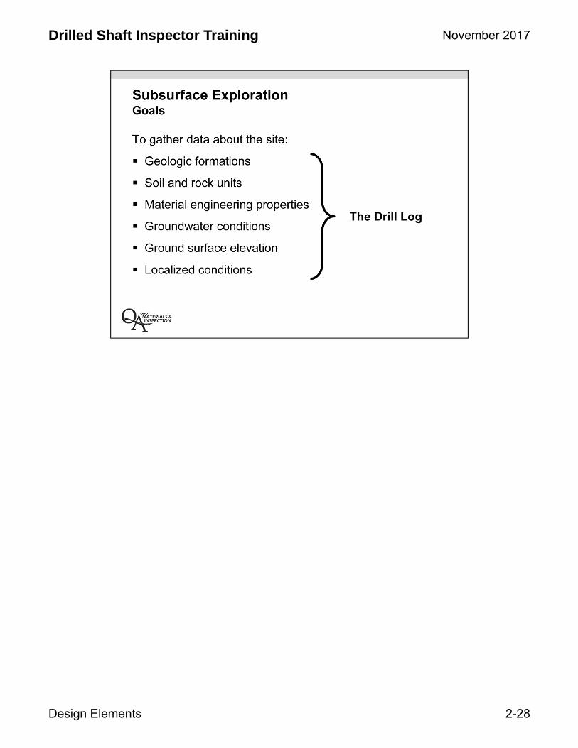
The Geologic Investigation section of the report frequently references the Geology Report, some times this report or portions of it, such as the drill logs and laboratory data summary, are appended to the Geotechnical Report. Generally laboratory testing data and groundwater conditions are discussed in this section of the report.
November 2017
Design Elements 2-6
Drilled Shaft Inspector Training

Liquefaction is the reduction in soil shear strength that typically sandy soils below the groundwater table can experience due to elevated pore water pressures during and immediately after a seismic event, resulting in a loss of support for axial (vertical) and lateral (horizontal) for bridge foundation and other loads. Settlement can also occur as a result of liquefaction. An example of this phenomenon can be observed when walking on a sandy ocean beach (something us Oregon folks have nearly 400 miles of), in the wetted portion of the tidal fluctuation zone. Immediately as you lift your foot you may have noticed that the sand has turned nearly to a liquid and will shake and shimmer as it displaces to partial fill your foot print. This is due to momentary elevated water pressure, which dissipates after which the sand returns to its normal state and strength.
Lateral spread is horizontal movement of the ground that may occur as a result of liquefaction, similar to landslide movement. This can be very damaging to bridge foundations.
November 2017
Design Elements 2-7
Drilled Shaft Inspector Training

Foundation design recommendations typical address the axial load carrying capacity of the drilled shafts as well as providing information (frequently contained in the appendix) that is used to define the subsurface model to characterize the lateral load capacity/deflection of the drilled shaft foundation. The required diameter, length and resistance factors (the geotechnical portion of the older term simply known as “factor of safety” aka FS and FOS) are typically stated. In some cases the axial load capacity, diameter and length may be provided in tabular or graphical format manner so that the Structural Engineer can evaluate the required foundation parameters for variable loads or to compare different design alternatives (different span configurations, superstructure types, number of drilled shafts per bent, etc). The type of drilled shaft, end bearing or skin friction, is also stated as it is pertinent to the clean out requirement in SS00512.44(h). This topic will be discussed in more detail later in this lesson and others.
Geotechnical design recommendations generally pertain to earthwork elements.
November 2017
Design Elements 2-8
Drilled Shaft Inspector Training

The construction recommendations section of the report is written specifically for the inspector and if there is only one section of the report you read, this should be it, although the report should be read in its entirety for the fullest understanding.
November 2017
Design Elements 2-9
Drilled Shaft Inspector Training

Special provisions are where the rubber meet the road. These, along with the plans, become contract documents once incorporated into the special provisions in the “brown” book specs. This is where the design requirements are codified such that the design intent is provided.
November 2017
Design Elements 2-10
Drilled Shaft Inspector Training

November 2017
Design Elements 2-11
Drilled Shaft Inspector Training

This information was for a Region 3 drilled shaft supported bridge project just west of Sutherlin, Calapooya Creek Bridge. The drilled shaft was installed in the August of 2011 and it will be our “go to” project for a number of the examples in this course. The interior bent of a two span bridge is supported on a single 8′ diameter drilled shaft installed to a depth of 50′ in extremely soft Mudstone Bedrock. This is an example of a side (skin) friction shaft.
November 2017
Design Elements 2-12
Drilled Shaft Inspector Training

The Construction Recommendations in this example discuss the nature of the extremely soft Mudstone Bedrock and how it is anticipated to be sensitive to changes in moisture content and what actions can be taken to mitigate this concern.
November 2017
Design Elements 2-13
Drilled Shaft Inspector Training

Excavated mudstone from the Calapooya Creek drilled shaft.
November 2017
Design Elements 2-14
Drilled Shaft Inspector Training
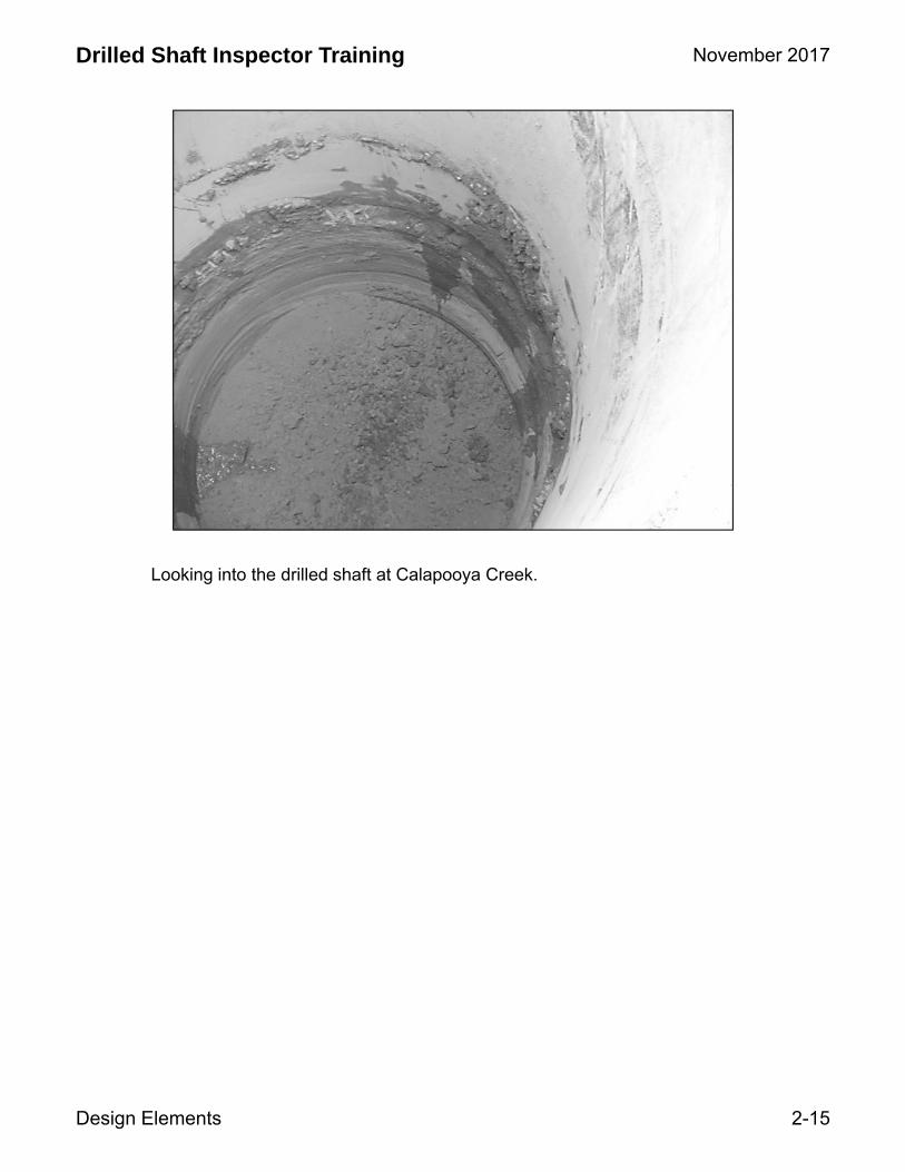
Looking into the drilled shaft at Calapooya Creek.
November 2017
Design Elements 2-15
Drilled Shaft Inspector Training

November 2017
Design Elements 2-16
Drilled Shaft Inspector Training

In this FDS the Mudstone Bedrock contact is fairly plainer and level on the basis of the seven test holes.
Standard Penetration Test (SPT) blow counts are denoted with small black boxes on the vertical edge of the graphical stick log. Information for the rock core is noted in the tables. These aspects will be discussed in more detail later in this lesson.
A full size copy of this image is included in the plans in the Drilled Shaft Resource Manual, page 78 of 166, Drawing No. 84336. Hole No. 7 represents the drilled shaft location.
The bridge design includes piles on the ends with a less expensive drilled shaft in the middle. Environmental concerns were expressed concerning a spread footing in the middle (larger footprint) than drilled shaft.
November 2017
Design Elements 2-17
Drilled Shaft Inspector Training

November 2017
Design Elements 2-18
Drilled Shaft Inspector Training

In actuality few drilled shafts are truly either end bearing or side friction drilled shafts as most drilled shafts have components of both which contribute to the axial load capacity. The contribution of axial capacity from either end bearing or side friction is a function of how much vertical deflection (settlement) occurs (or is tolerable) due to the dead load the foundations are under. This is known as “strain compatibility” with the conventional wisdom being that it takes significantly more settlement to mobilize end bearing than it does side friction.
An example condition where end bearing shafts would be designed are where the subsurface profile indicates very soft or loose soil over “strong” rock.
An example condition where side (skin) friction shafts would be designed are where the subsurface profile indicates stiff or dense soil or “weak” rock.
November 2017
Design Elements 2-19
Drilled Shaft Inspector Training

November 2017
Design Elements 2-20
Drilled Shaft Inspector Training

November 2017
Design Elements 2-21
Drilled Shaft Inspector Training

There are several reasons why it is important to know whether the drilled shaft is end bearing or skin friction. Clean-out is one aspect; other is to make sure the tip is where it is suppose to be.
SS00512.43(h) Clean Out – Use appropriate means, such as a cleanout bucket, pump or air lift, to clean the bottom of the drilled shaft excavations. No more than 2 inches of loose or disturbed material will be allowed at the bottom of the excavation for end-bearing drilled shafts. No more than 6 inches of loose or disturbed material will be allowed at the bottom of the excavation for side friction drilled shafts. Assume end-bearing shafts unless otherwise shown or specified. Shaft cleanliness will be determined by the Engineer.
Notify the Engineer of completion of each drilled shaft excavation to permit inspection before proceeding with construction. Measure final shaft depths with a suitable weighted tape or other approved method after final cleaning to determine that the shaft bottom meets the requirements in the Contract. Do not proceed with shaft construction until the bottom cleanliness requirements have been met and the bottom (shaft tip) elevation is approved.
November 2017
Design Elements 2-22
Drilled Shaft Inspector Training

Groundwater conditions vary seasonally.
The Foundation Data Sheet will typically contain the groundwater level for the date the test hole was drilled.
Some geotechnical exploration drilling methods introduce water during the drilling process and may prevent groundwater levels from being collected.
Occasionally (rarely for bridge foundation projects) groundwater monitoring instrumentation is installed in test holes and groundwater level data variations over a period of time can be collected. If that data has been collected it will be discussed in the Geotechnical and Geology Reports and it will be noted on the drill log.
November 2017
Design Elements 2-23
Drilled Shaft Inspector Training

SS00512.47(b) Dry Shaft Concrete Placement – Concrete may be placed by free-fall if all of the following conditions are met:
• No more than 3 inches of water is present in the bottom of the excavation at the beginning of the pour.
• Groundwater seepage into the excavation is at a rate of no more than 12 inches per hour.
• Shaft diameter is greater than or equal to 3 feet.
Under free-fall placement, deposit concrete through the center of the reinforcement cage by a method which prevents segregation of aggregates and splashing of concrete on the reinforcement cage. Place concrete so that the free-fall is vertical down the center of the shaft without hitting the sides, the steel reinforcing bars or steel cage bracing.
SS00512.47(c) Wet Shaft Concrete Placement – If the drilled shaft excavation does not meet the requirements for dry concrete placement, stabilize water inflow and place the concrete under water or slurry with a tremie pipe or pump hose according to 00540.48(e). Place concrete continuously from the bottom of the shaft to the top-of-shaft elevation shown. Use a plug in the tremie pipe or pump hose to force water or slurry ahead of the advancing flow of fresh concrete. Dispose of all displaced water, slurry, or waste concrete according to 00290.20. When groundwater, the drilling water or slurry in the shaft excavation is to be removed by pumping during concrete placement, have a standby pump available.
Place concrete in a continuous operation so that the concrete always flows upward within the shaft. Withdraw the delivery hose or pipe slowly as the elevation of the fresh concrete rises in the shaft. Keep the discharge end of the pipe or hose at least 5 feet below the surface of the concrete after the concrete has reached a depth of 5 feet. Maintain sufficient concrete inside the hose or pipe to prevent drilling fluid from entering. During concrete placement, provide and maintain markings on the tremie pipe or pump hose, or a sounding device or other appropriate method to determine the relative elevations of the fresh concrete surface and the bottom end of the pipe or hose. Raise the bottom end of the pipe or hose only when the pipe or hose has a sufficient head of fresh concrete to prevent the formation of a void at the bottom.
November 2017
Design Elements 2-24
Drilled Shaft Inspector Training

November 2017
Design Elements 2-25
Drilled Shaft Inspector Training

Test holes are not to be terminated in incompetent material (peat, loose sand, soft clay)!
November 2017
Design Elements 2-26
Drilled Shaft Inspector Training

Test holes are not to be terminated in incompetent material (peat, loose sand, soft clay)!
November 2017
Design Elements 2-27
Drilled Shaft Inspector Training
November 2017
Design Elements 2-28
Drilled Shaft Inspector Training

A variety of drilling methods are typically used:
• Hollow Stem Auger (ASTM D6151)
• Mud Rotary (ASTM D5783)
• Wire Line Casing Advancement (ASTM D5876)
A variety sampling methods are typically used:
• Standard Penetration Tests, blow counts, N-values (ASTM D1586)
• Thin-walled tube sampling, undisturbed samples, Shelby tube (ASTM D1587)
• Rock Core (ASTM D2113)
There are a number of other less common soil and rock sampling and insitu testing methods used. The more common methods, which typically result in numerical information that is presented directly on the drill log and Foundation Data Sheet are those discussed herein.
The SPT makes use of a split spoon sampler with an outside diameter (O.D.) of 2.0 inches and inside diameter (I.D.) of 1.5 inches and either 18 or 24 inches long that is driven into soils and weak rock with hammer that weights 140 pounds that is dropped 30 inches. The split spoon sampler is fitted with a drive shoe with an O.D. of 2.0 inches and an I.D. of 1-3/8 inches ODOT and our drilling contractors typically use an auto trip safety hammer which minimizes the safety risks posed be the hammering process. The number of blows taken to drive each of three, 6-inch successive intervals is recorded. The sum of the last two 6-inch intervals is known as the N-value.
Shelby tube samples are known as undisturbed samples as they are pushed rather than pounded in to soft soils and they are thin walled (about 1/16 inches vs. the 5/16 inches for SPTs), therefore disturbing the soil less than the SPT. The outside diameter is typically 3 inches for ODOT work and the length is typically 30 inches.
November 2017
Design Elements 2-29
Drilled Shaft Inspector Training

This series of slide shows the rope and cat head method of SPT commonly used from the from about 1940 through the 1980’s. The method of lifting the weight was a rope that was pulled by friction when tightened by the driller pulling on it while it was wrapped 2 or 3 times around a continuously rotating pulley (known as a cat head). The hammer would drop when the driller released the tension on the rope. The height of the hammer fall was largely a function of the skill of the driller and was subject to being greater than or less than the desired 30 inches. The rope and cat head method was typically about 60% efficient in converting potential energy to kinetic energy. Auto trip safety hammers are commonly used with modern drilling equipment and typically have an efficiency of greater than 80%.
November 2017
Design Elements 2-30
Drilled Shaft Inspector Training

November 2017
Design Elements 2-31
Drilled Shaft Inspector Training

November 2017
Design Elements 2-32
Drilled Shaft Inspector Training

November 2017
Design Elements 2-33
Drilled Shaft Inspector Training

November 2017
Design Elements 2-34
Drilled Shaft Inspector Training

November 2017
Design Elements 2-35
Drilled Shaft Inspector Training

November 2017
Design Elements 2-36
Drilled Shaft Inspector Training

November 2017
Design Elements 2-37
Drilled Shaft Inspector Training

The rock core recovery is expressed as a percentage calculated as the length of rock core recovered by the length of the rock core run (typically 5 feet).
From ODOT’s 1987 Soil and Rock Classification Manual:
Core Recovery and Rock Quality Designation (RQD)Core recovery and the Rock Quality Designation are measured indicators of the quality and structure of rock. Both the percent core recovery and the RQD should be determined and recorded on the field boring log for each core run. The core recovery is calculated by dividing the length of the core retained (recovered) in the core barrel by the total run length expressed as a percent.
November 2017
Design Elements 2-38
Drilled Shaft Inspector Training

November 2017
Design Elements 2-39
Drilled Shaft Inspector Training

From ODOT’s 1987 Soil and Rock Classification Manual:
The RQD provides a subjective estimate of rock mass quality/structure. The RQD is a modified core recovery percentage in which only pieces of intact rock core 4 inches or greater in length are measured (average length). The smaller pieces are considered to be the result of close jointing, fracturing or weathering in the rock mass, and are therefore excluded from the RQD determination. The RQD is defined as the cumulative total length of all pieces 4 inches long or longer divided by the total run length, expressed as a percentage. Mechanical breaks, such as caused by handling or drilling, should be noted as such and not included in the RQD calculations.
In some cases, where significant soil is encountered at one of the core run, the RQD should be determined on the basis of rock core length recovered: where this is done it should be clearly defined. RQD is not applicable to fissle rocks such as shales. Difficulties such as distinguishing natural fractures in the rock core from mechanical breaks and the insensitivity of the RQD to the tightness of individual joints may limit the use of the RQD in evaluating in situ rock properties.
November 2017
Design Elements 2-40
Drilled Shaft Inspector Training

November 2017
Design Elements 2-41
Drilled Shaft Inspector Training

November 2017
Design Elements 2-42
Drilled Shaft Inspector Training

November 2017
Design Elements 2-43
Drilled Shaft Inspector Training

November 2017
Design Elements 2-44
Drilled Shaft Inspector Training
November 2017
Design Elements 2-45
Drilled Shaft Inspector Training

November 2017
Design Elements 2-46
Drilled Shaft Inspector Training

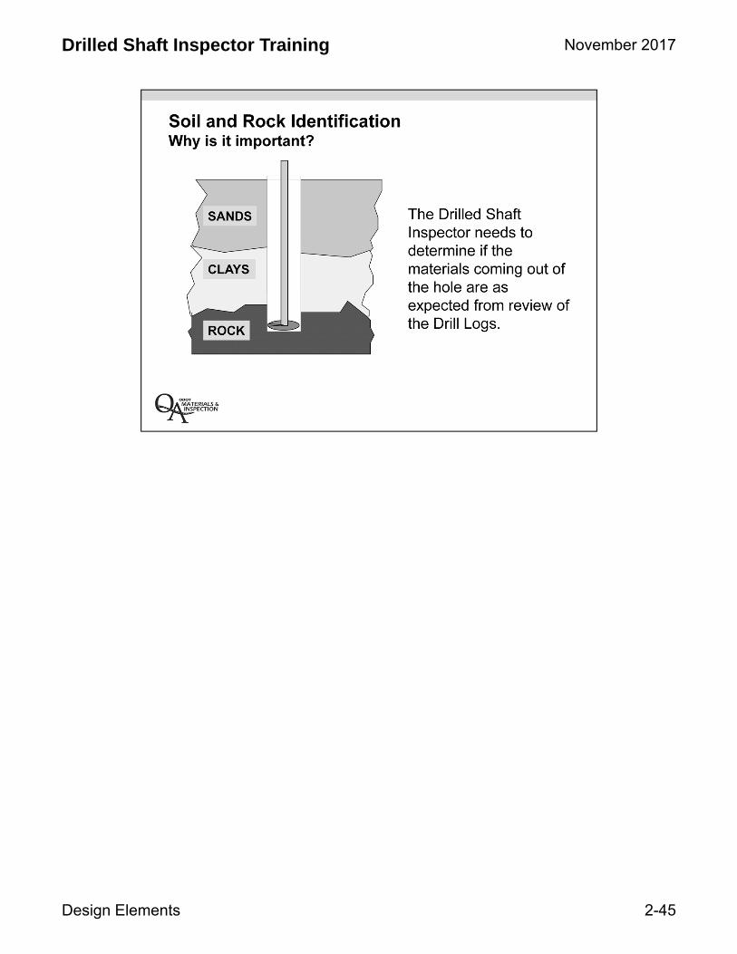
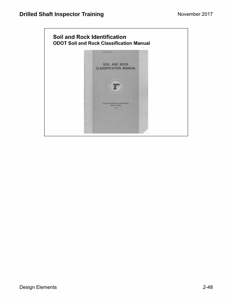
ODOT’s reference for soil and rock identification is the ODOT Soil and Rock Classification Manual, 1987. Note that definitions of soil and rock are included in the Volume 1 of Oregon Standard Specifications for Construction.
November 2017
Design Elements 2-47
Drilled Shaft Inspector Training
November 2017
Design Elements 2-48
Drilled Shaft Inspector Training

Soils are defined by their principal size components.
Gravel and sand are coarse-grained components that can be distinguished by eye.
ODOT defines gravel as particles between 3 inches and the number 4 sieve (about 0.2 inches). Sand is defined as particle sizes between the number 4 and number 200 sieves (0.187 and 0.0029 inches, about the diameter of a human hair).
Silt and clay are fine-grained components, too fine to distinguish individual grains. Silt is particle smaller that the 200 sieve (0.0029 inches) and clay is particle smaller than 0.0002 inches (about 1/15th the diameter of a human hair).
November 2017
Design Elements 2-49
Drilled Shaft Inspector Training

Silt and Clay are distinguished based on their physical behavior relative to plasticity and behavior at certain moisture contents (Atterberg Limits) .
November 2017
Design Elements 2-50
Drilled Shaft Inspector Training

Rock is classified with respect to its geological origin as follows:
a. Igneous Rocks, such as granite, diorite, and basalt, are formed by the solidification of molten materials, either at depth in the earth’s crust or by extrusion at the earth’s surface.
b. Sedimentary Rocks, such as conglomerate, sandstone and mudstone are formed by the lithification of sedimentary soils.
c. Metamorphic Rocks, such as quartzite, schist, gneiss, and greenstone which were originally igneous or sedimentary rocks, have been altered physically, sometimes chemically, by the application of intense heat and/or pressure at some time in their geologic history.
November 2017
Design Elements 2-51
Drilled Shaft Inspector Training
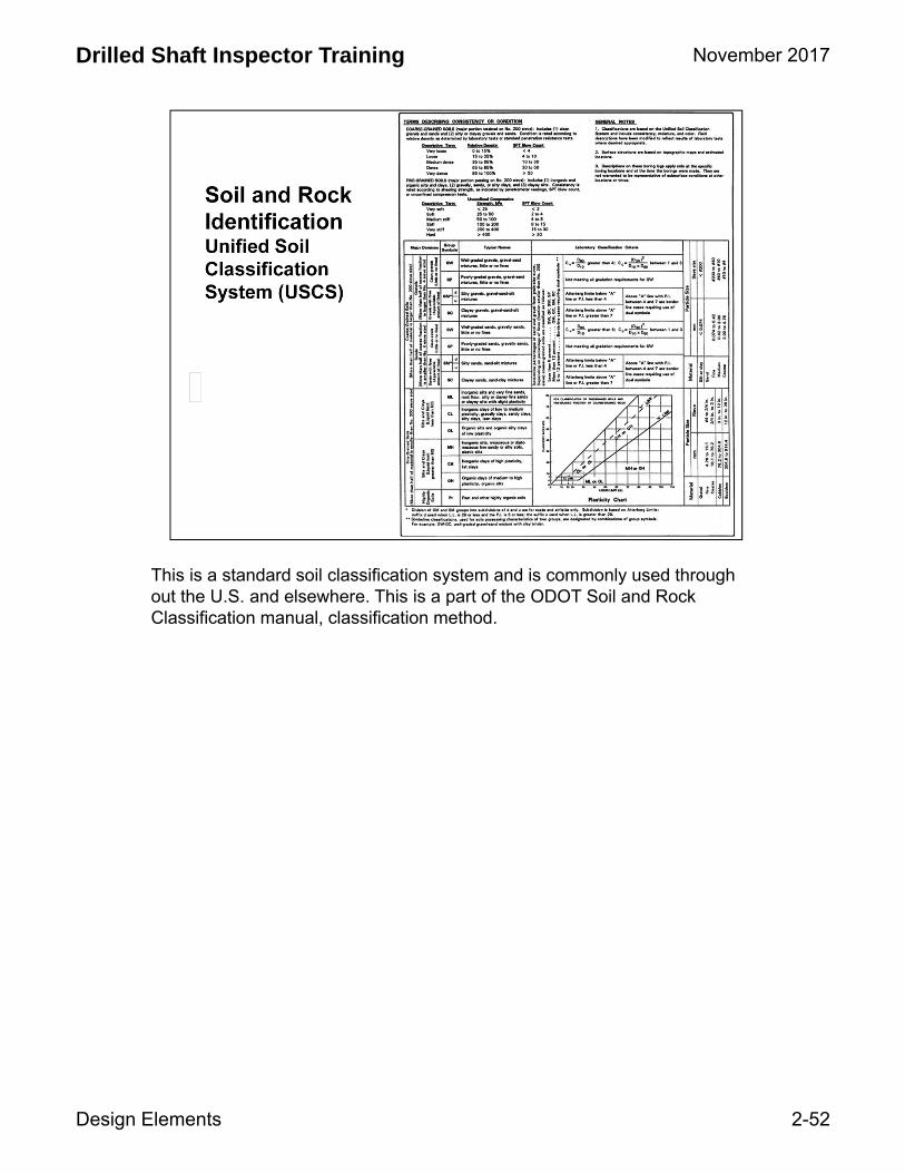
This is a standard soil classification system and is commonly used through out the U.S. and elsewhere. This is a part of the ODOT Soil and Rock Classification manual, classification method.
November 2017
Design Elements 2-52
Drilled Shaft Inspector Training

November 2017
Design Elements 2-53
Drilled Shaft Inspector Training

November 2017
Design Elements 2-54
Drilled Shaft Inspector Training

November 2017
Design Elements 2-55
Drilled Shaft Inspector Training

Reference for naming soils.
November 2017
Design Elements 2-56
Drilled Shaft Inspector Training

November 2017
Design Elements 2-57
Drilled Shaft Inspector Training

This is a typical Drill Log (only page 1 of 4 is shown).
Note the abbreviations defined in the upper 1/3 of the log. These define the test type, provide additional rock information and drilling methods and notes.
The Drilled Shaft Inspector should become familiar with the information contained on the drill logs sheets for each test hole as this information is more detailed than the Foundation Data Sheet contained in the contract plans.
The location of each test hole is shown on the Foundation Data Sheet.
Individual sample descriptions are provided as well as geologic and engineering unit descriptions. SPT blow counts and depths are noted, rock core information is provided. Drilling methods and groundwater levels are noted and instrumentation which may have been placed in the test hole is recorded.
Locate the full size drill log Hole No. 14813-07 in the Drilled Shaft Resource Manual. Can you identify the following on the drill log?
• Material sample and unit descriptions• A symbolic view of the materials encountered• Symbols for ground water table, loss of circulation, etc.• Density and consistency of materials based upon “N” values• Rock core data• Laboratory test results
November 2017
Design Elements 2-58
Drilled Shaft Inspector Training

November 2017
Design Elements 2-59
Drilled Shaft Inspector Training

November 2017
Design Elements 2-60
Drilled Shaft Inspector Training