Embed Size (px)
Citation preview

Standard and Special Provisions to be familiar with:00512 – Drilled Shafts00530 – Steel Reinforcement for Concrete00540 – Structural Concrete02001 – Concrete00290 – Environmental Protection
Documents that you will need:Drilled Shaft Inspector’s ChecklistDrilled Shaft Installation PlanDrilled Shaft Inspector’s ReportDrilled Shaft Concrete VolumesDrilled Shaft Concrete Volume Logs
November 2017
Concrete Operations 7-1
Drilled Shaft Inspector Training
November 2017
Concrete Operations 7-2
Drilled Shaft Inspector Training

Change to checklist image.
November 2017
Concrete Operations 7-3
Drilled Shaft Inspector Training

November 2017
Concrete Operations 7-4
Drilled Shaft Inspector Training

OSSC 2015
00512.12 Concrete Mix Design - Design the drilled shaft concrete for minimum segregation. Use the Engineer's reviewed and approved mix design.
• Add water to the concrete mix at the Project Site only if allowed by the approved mix design. Accurately measure water added at the site by water meters, buckets or other approved devices. Limit the addition of water at the Project Site to 1 gallon per cubic yard.
• Provide concrete having the appropriate initial slump according to Table 02001-3. Use chemical admixtures from the QPL to control and maintain slump and to facilitate temporary casing extraction.
• Design the concrete mix to maintain at least 4 inches of slump after placement and throughout the entire duration of the pour including during temporary casing extraction.
November 2017
Concrete Operations 7-5
Drilled Shaft Inspector Training

November 2017
Concrete Operations 7-6
Drilled Shaft Inspector Training

November 2017
Concrete Operations 7-7
Drilled Shaft Inspector Training

November 2017
Concrete Operations 7-8
Drilled Shaft Inspector Training

November 2017
Concrete Operations 7-9
Drilled Shaft Inspector Training

November 2017
Concrete Operations 7-10
Drilled Shaft Inspector Training

November 2017
Concrete Operations 7-11
Drilled Shaft Inspector Training

November 2017
Concrete Operations 7-12
Drilled Shaft Inspector Training

November 2017
Concrete Operations 7-13
Drilled Shaft Inspector Training

OSSC 201502001.35 Required Submittals for Mix Designs - Submit the following information for each concrete mix design:(a) Supplier's Unique Mix Design Identification Number(b) Mix Design Constituent Proportions:• Weight per cubic yard (pounds per cubic yard) of cementitious material, modifiers, fine and coarse aggregates (SSD), and mix water.• Absolute volumes of cementitious material, modifiers, fine aggregates and coarse aggregates (SSD), and mix water.• Dosage rates for chemical admixtures.(c) Aggregates - Identify the aggregate source by the ODOT source number. Report current valuesof the following:• Bulk specific gravities (SSD)• Fine aggregate absorptions• Coarse aggregate absorptions• Dry-rodded density of coarse aggregates• Fineness modulus of sand used in the mix design calculations(d) Cementitious Material - For each cementitious material used, identify the following:• Manufacturer• Brand name• Type• Relevant Specification• Source or location plant(e) Modifiers - For each modifier used, identify the following:• Manufacturer• Brand name• Source• Relevant specification• Class(f) Admixtures - For each admixture used, identify the following:• Manufacturer• Brand name• Design dosage rate(g) Water - Identify the source of water to be used.(h) Plastic Concrete Tests - Report the temperature, slump, density, air content, yield, and w/cm ratio of the trial batch or the average of these values for the cylinder sets presented for evaluation of a current mix design.(i) Compressive Strength Test Results - Report the individual test results and the ASTV of cylinders from the trial batch or the average for the cylinder sets presented for evaluation of a current mix design.(j) Strength Analysis - Provide an analysis, showing all calculations, demonstrating that the mix design meets the requirements of 02001.33.(k) Quality Control Personnel - Provide the name and certification number of the CCT who prepared the mix design, the QCT who performed the plastic concrete tests and cast the test cylinders, the laboratory where the cylinders were tested, and the CSTT who tested the cylinders.
November 2017
Concrete Operations 7-14
Drilled Shaft Inspector Training

November 2017
Concrete Operations 7-15
Drilled Shaft Inspector Training

November 2017
Concrete Operations 7-16
Drilled Shaft Inspector Training

November 2017
Concrete Operations 7-17
Drilled Shaft Inspector Training

November 2017
Concrete Operations 7-18
Drilled Shaft Inspector Training

November 2017
Concrete Operations 7-19
Drilled Shaft Inspector Training

November 2017
Concrete Operations 7-20
Drilled Shaft Inspector Training

November 2017
Concrete Operations 7-21
Drilled Shaft Inspector Training

November 2017
Concrete Operations 7-22
Drilled Shaft Inspector Training

4″ Minimum slump has been changed to 6” in OSSC 2015
OSSC 2015SP00512.12 Concrete Mix Design - Delete this subsection.
SP02001.20(c) Slump - Add the following paragraph to the end of this subsection:
For drilled shaft concrete, maintain a minimum slump of 6 inches throughout the drilled shaft placement, including temporary casing extraction.
SP02001.35(h) Plastic Concrete Tests - Add the following paragraph and bullets to the end of this subsection:
For drilled shaft concrete, report the following additional information:
• The total time estimate from initial batching through drilled shaft placement, including haul time, placing concrete, and temporary casing extraction.
• Initial slump test results and subsequent results at 15-minute intervals, verifying a minimum slump of 6 inches is maintained for the total time estimated for drilled shaft placement, including temporary casing extraction. Report data in a table or graph format.
November 2017
Concrete Operations 7-23
Drilled Shaft Inspector Training

November 2017
Concrete Operations 7-24
Drilled Shaft Inspector Training

November 2017
Concrete Operations 7-25
Drilled Shaft Inspector Training

November 2017
Concrete Operations 7-26
Drilled Shaft Inspector Training

November 2017
Concrete Operations 7-27
Drilled Shaft Inspector Training

The Drilled Shaft mix design needs to follow the concrete mix design submittal requirements of 02001. Consequently - there really is no "transfer" meaning here's a mix design (Lab Report) from this other project -> please assign it to this current project. There are a number of concerns with the "transfer" approach. We've had instances where a mix design approved on a project is then approved on other projects sometimes without any direct contact or involvement from the Concrete Producer. This could be a problem if the Concrete Producer wants or needs to change an additive or update the physical properties of materials. So there's a little more to it than just passing a recipe.
A recent example - a previously approved version of a Drilled Shaft mix used GGBFS instead of fly ash due to a shortage of fly ash when that particular mix design was reviewed. The Concrete Producer had since gone back to fly ash but I had a request to "transfer" the Drilled Shaft mix design with GGBFS. You see the problem?
So the contractor needs to send in a complete submittal for each Contract.
As you now or are learning ~ Drilled Shaft concrete has two critical submittals. The Drilled Shaft mix design which is evaluated according to 00512.12 and 02001 and the Drilled Shaft Installation Plan evaluated according to 00512.40 Submittals.
I'm sure that some people have assumed that an approved mix design = an approved Drilled Shaft Installation Plan. NOT TRUE! I do not review nor approve the Drilled Shaft Installation Plan. The mix design (being a separate submittal) is but one aspect of the Drilled Shaft Installation Plan. Therefore -the mix design submittal should typically precede the Drilled Shaft Installation Plan.
One of the things that I look for concerns the slump retention (workability) requirement of the specifications. The concrete producer may or may not identify the anticipated duration of the drilled shaft placement. However, there will usually be an additive used to hold the slump as required. The exact details about duration of the placement - are to be included in and assured by the Drilled Shaft Installation Plan which has its own 21-day review period.
Call me if you still have any questions.
Austin Johnson503.986.5461
November 2017
Concrete Operations 7-28
Drilled Shaft Inspector Training

Contractor may want to add water to the concrete at the job site for various reasons:
- increase workability
- increase slump
- change the temperature
In adding water to the concrete the mix design is effectively changed. By adding water this changes important concrete parameters such as:
- water/cement ratio
- strength
- slump
- density
OSSC 2015
00512.12 Concrete Mix Design - Design the drilled shaft concrete for minimum segregation. Use
The Engineer's reviewed and approved mix design.
• Add water to the concrete mix at the Project Site only if allowed by the approved mix design.
Accurately measure water added at the site by water meters, buckets or other approved
devices. Limit the addition of water at the Project Site to 1 gallon per cubic yard.
SP00512.12 Concrete Mix Design - Delete this subsection.
02001 and SP2001 does not allow for the addition of water unless it is approved in the mix design!
November 2017
Concrete Operations 7-29
Drilled Shaft Inspector Training

November 2017
Concrete Operations 7-30
Drilled Shaft Inspector Training

November 2017
Concrete Operations 7-31
Drilled Shaft Inspector Training

OSSC 2015
00512.47 Concrete – furnish and place concrete according to the following:
(b) Dry Shaft Concrete Placement - Concrete may be placed by free-fall if all of the following conditions are met:
• no more than 3 inches of water is present in the bottom of the excavation at the beginning of the pour
• groundwater seepage into the excavation is at a rate of no more than 12 inches per hour
• shaft diameter is greater than or equal to 3 feet
Under free-fall placement, deposit concrete through the center of the reinforcement cage by a method which prevents segregation of aggregates and splashing of concrete on the reinforcement cage. Place concrete so that the free-fall is vertical down the center of the shaft without hitting the sides, the steel reinforcing bars or steel cage bracing.
November 2017
Concrete Operations 7-32
Drilled Shaft Inspector Training

What are the safety issues?
Tie-off,
hard hat.
Note Beaver Ball – contaminated concrete
Drilled Shaft Inspector Training
Concrete Operations 33
November 2017
Concrete Operations 7-33
Drilled Shaft Inspector Training

November 2017
Concrete Operations 7-34
Drilled Shaft Inspector Training

Placement of concrete by freefall into a wet shaft is not allowed.
OSSC 2015
00512.47 Concrete - Furnish and place concrete according to the following:
(c) Wet Shaft Concrete Placement - If the drilled shaft excavation does not meet the requirements for dry concrete placement, stabilize water inflow and place the concrete under water or slurry with a tremie pipe or pump hose according to 00540.48(e). Place concrete continuously from the bottom of the shaft to the top-of-shaft elevation shown. Use a plug in the tremie pipe or pump hose to force water or slurry ahead of the advancing flow of fresh concrete. Dispose of all displaced water, slurry, or waste concrete according to 00290.20. When groundwater, the drilling water or slurry in the shaft excavation is to be removed by pumping during concrete placement, have a standby pump available. Place concrete in a continuous operation so that the concrete always flows upward within the shaft. Withdraw the delivery hose or pipe slowly as the elevation of the fresh concrete rises in the shaft. Keep the discharge end of the pipe or hose at least 5 feet below the surface of the concrete after the concrete has reached a depth of 5 feet. Maintain sufficient concrete inside the hose or pipe to prevent drilling fluid from entering. During concrete placement, provide and maintain markings on the tremie pipe or pump hose, or a sounding device or other appropriate method to determine the relative elevations of the fresh concrete surface and the bottom end of the pipe or hose. Raise the bottom end of the pipe or hose only when the pipe or hose has a sufficient head of fresh concrete to prevent the formation of a void at the bottom.
November 2017
Concrete Operations 7-35
Drilled Shaft Inspector Training

November 2017
Concrete Operations 7-36
Drilled Shaft Inspector Training

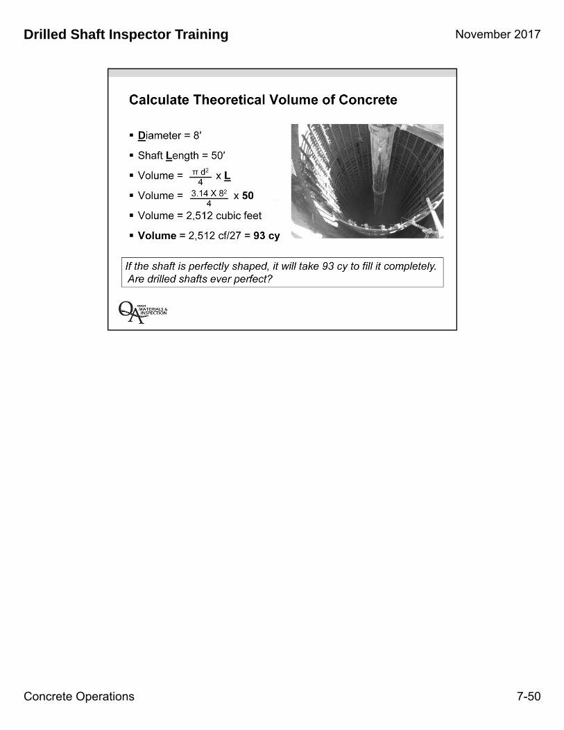
There must be enough concrete to “overflow” the shaft to push out the water, soil, etc. until there is uncontaminated concrete.
This picture shows an example where “overflow” is not happening.
OSSC 2015
00512.47 Concrete - Furnish and place concrete according to the following:
Place concrete continuously until concrete at the top of the shaft is free of water, soil, and debris, and uncontaminated concrete extends to the plan top-of-shaft elevation. Dispose of all contaminated concrete expelled from the top of the shaft in an approved manner. Remove waste concrete from the site. If a delay in concrete placement occurs because of a delay in concrete delivery or other factors, reduce the placement rate to maintain a flow of fresh concrete into the shaft excavation
November 2017
Concrete Operations 7-37
Drilled Shaft Inspector Training

OSSC 2015
(e) Casing Removal - Remove all temporary casing during or after completion of concrete placement. Do not start temporary casing removal until the level of fresh concrete within the casing has reached a depth of at least 10 feet or the level necessary to adequately counteract the external hydrostatic pressure head. As the temporary casing is withdrawn, maintain a minimum 5 feet head of concrete above the bottom of the casing. A slight downward movement of the casing while exerting downward pressure, or hammering or vibrating the casing will be allowed to facilitate extraction.
Extract the casing so that concrete is cast directly against the surrounding in-situ material. Check the elevation of the top of the reinforcing cage before and after temporary casing extraction for conformance with the construction tolerance criteria of 00512.42. Casing that cannot be extracted during, or immediately after, the concrete placement operation may be cause for rejection of the shaft.
Remove the tops of permanent casing to the top of the drilled shaft or the finished groundline, whichever is lower, unless otherwise shown or directed. Remove the tops of permanent casing for shafts constructed in a permanent body of water to the low water elevation, unless otherwise shown or directed.
November 2017
Concrete Operations 7-38
Drilled Shaft Inspector Training

November 2017
Concrete Operations 7-39
Drilled Shaft Inspector Training

On first test, at ODOT have Region come out and do Verification testing through the Region Quality Assurance Coordinator.
November 2017
Concrete Operations 7-40
Drilled Shaft Inspector Training

November 2017
Concrete Operations 7-41
Drilled Shaft Inspector Training

November 2017
Concrete Operations 7-42
Drilled Shaft Inspector Training

Filling the CSL tubes with water allows the CSL tubes to remain at the same temperature as the concrete so that they do not debond from the concrete.
Debonding from the concrete will result in erroneous CSL test results.
Crosshole sonic log testing requires access tubes cast into the shaft concrete and attached inside the steel cage. The access tubes for CSL testing are always steel to provide the best possible bond between the tube and the concrete. These tubes need to be cast into the concrete at the time of construction. The tubes must be filled with water to dissipate heat from concrete curing process. Without water in the tubes they may debond from the concrete rendering them useless for testing.
It is very important that the tubes are installed on the proper spacing and maintain a straight alignment the full length of the shafts. The results of the test are affected by the distance between each pair of tubes.
Different tests require different types of tubes (e.g., PVC for gamma-gamma versus schedule 40 steel for CSL). Some tests require that the tubes are filled with water, and some don’t.
OSSC 2015
00512.46 Crosshole Sonic Log Test Access Tubes - Furnish and install access tubes for CSL
testing as shown. Attach CSL access tubes securely to the interior of the reinforcement cage as near to parallel as possible in each drilled shaft and in the pattern shown. Extend the access tubes from the bottom of the reinforcement cage to at least 24 inches above the top of the shaft. Joints required to achieve full-length access tubes shall be watertight. Do not damage the access tubes during reinforcement cage installation and concrete placement. Fill the tubes with potable water, according to 02020.10(b), as soon as possible, but no more than one hour after concrete placement and reinstall the top watertight caps. Check water level and top off as needed.
Replace all access tubes that the test probe cannot pass through to the full depth of the shaft at no additional cost to the Agency. Replace all damaged access tubes with 1.5 inch to 2.0 inch diameter holes cored through the concrete for the entire length of the shaft. Unless otherwise directed, locate replacement core holes approximately 6 inches inside the reinforcement. Do not damage the shaft reinforcement during coring operations.
Fill the access tubes with grout only after all CSL testing has been completed and the shaft has been accepted.
November 2017
Concrete Operations 7-43
Drilled Shaft Inspector Training

OSSC201500512.40 Submittals - Provide the following submittals to the Agency for review and approval:
(c) Drilled Shaft Inspection Reports - Provide the Engineer with a completed Drilled Shaft Inspection Report for each drilled shaft, detailing the actual location, alignment, elevations, dimensions, and quantities of the shafts. Submit the report within 21 calendar days after the completion and acceptance of each shaft. A "Drilled Shaft Inspection Report" form is available from the Engineer.
(d) Concrete Placement Logs and Volume Curves - Measure and record all concrete placed into drilled shafts using standard ODOT forms designated for this purpose or other forms approved by the Engineer. Provide the Engineer with a completed Drilled Shaft Concrete Placement Log and Concrete Volume Curve Form for each drilled shaft within 24 hours after completion of shaft concrete placement.
November 2017
Concrete Operations 7-44
Drilled Shaft Inspector Training

OSSC201500512.40 Submittals - Provide the following submittals to the Agency for review and approval:
(c) Drilled Shaft Inspection Reports - Provide the Engineer with a completed Drilled Shaft Inspection Report for each drilled shaft, detailing the actual location, alignment, elevations, dimensions, and quantities of the shafts. Submit the report within 21 calendar days after the completion and acceptance of each shaft. A "Drilled Shaft Inspection Report" form is available from the Engineer.
(d) Concrete Placement Logs and Volume Curves - Measure and record all concrete placed into drilled shafts using standard ODOT forms designated for this purpose or other forms approved by the Engineer. Provide the Engineer with a completed Drilled Shaft Concrete Placement Log and Concrete Volume Curve Form for each drilled shaft within 24 hours after completion of shaft concrete placement.
November 2017
Concrete Operations 7-45
Drilled Shaft Inspector Training

OSSC201500512.40 Submittals - Provide the following submittals to the Agency for review and approval:
(c) Drilled Shaft Inspection Reports - Provide the Engineer with a completed Drilled Shaft Inspection Report for each drilled shaft, detailing the actual location, alignment, elevations, dimensions, and quantities of the shafts. Submit the report within 21 calendar days after the completion and acceptance of each shaft. A "Drilled Shaft Inspection Report" form is available from the Engineer.
(d) Concrete Placement Logs and Volume Curves - Measure and record all concrete placed into drilled shafts using standard ODOT forms designated for this purpose or other forms approved by the Engineer. Provide the Engineer with a completed Drilled Shaft Concrete Placement Log and Concrete Volume Curve Form for each drilled shaft within 24 hours after completion of shaft concrete placement.
November 2017
Concrete Operations 7-46
Drilled Shaft Inspector Training

November 2017
Concrete Operations 7-47
Drilled Shaft Inspector Training

November 2017
Concrete Operations 7-48
Drilled Shaft Inspector Training
November 2017
Concrete Operations 7-49
Drilled Shaft Inspector Training
November 2017
Concrete Operations 7-50
Drilled Shaft Inspector Training

Drilled Shaft Inspector Training
Concrete Operations 51
November 2017
Concrete Operations 7-51
Drilled Shaft Inspector Training

November 2017
Concrete Operations 7-52
Drilled Shaft Inspector Training

November 2017
Concrete Operations 7-53
Drilled Shaft Inspector Training
November 2017
Concrete Operations 7-54
Drilled Shaft Inspector Training
November 2017
Concrete Operations 7-55
Drilled Shaft Inspector Training

November 2017
Concrete Operations 7-56
Drilled Shaft Inspector Training

November 2017
Concrete Operations 7-57
Drilled Shaft Inspector Training

November 2017
Concrete Operations 7-58
Drilled Shaft Inspector Training

November 2017
Concrete Operations 7-59
Drilled Shaft Inspector Training

November 2017
Concrete Operations 7-60
Drilled Shaft Inspector Training

November 2017
Concrete Operations 7-61
Drilled Shaft Inspector Training

• It is the contractors’ responsibility to complete the Concrete Placement Logs and Volume Curves.
• The drilled shaft inspector will keep ODOT’s own set of records.
• It is the Inspector’s responsibility to document on ODOT’s behalf.
November 2017
Concrete Operations 7-62
Drilled Shaft Inspector Training

November 2017
Concrete Operations 7-63
Drilled Shaft Inspector Training

November 2017
Concrete Operations 7-64
Drilled Shaft Inspector Training