Embed Size (px)
Citation preview

FACULTYOFSCIENCEANDTECHNOLOGY
Drillbotics2017
Studyprogram/specialization:
PetroleumEngineering–DrillingandWellEngineering
FallSemester,2016
Writers:
ErikAndreasLøken,PatrickHarris,OleAndréHjelm,SimenJøsangNilsen,AlexanderTrulsen
FacultySupervisor:DanSui
ExternalSupervisor:RobertEwald,InternationalResearchInstituteofStavanger(IRIS)
Title:
Drillbotics2017:RigDesignPrinciplesandDecemberUpdate2016/2017
Keywords:
• RigDesign
• AutonomousDrilling
• Drillbotics
• DrillingControl
• DrillingPerformance
• Autonomouscontrolsystems
Numberofpages:48(+appendix)
Stavanger,2016-12-31
UniversityofStavanger,2016-12-31
II
Contents:
Summary VI
1. ProblemDescription 1
2. Rig-andControlSystemArchitecture 22.1RigSystems 22.2ControlPrinciples 3
3. Rigdesign 53.1DrillStringCalculations 53.1.1PreliminaryMetallurgicalConsiderationsforTorque 53.1.2DrillString–Twist-Off 63.1.3MaximumAllowableOverpull 73.1.4MaximumAllowableWOB 73.2Bottom-HoleAssemblyDesignandConceptualization 83.2.1BasisofDesign 83.2.2BHAManufacturing 113.3CirculationSystem 123.3.1 Pump 123.3.2 RotaryUnion 133.3.3 Multi-TieredFiltrationSystem 143.3.3.1 DesignPrinciples 143.3.3.2 DesignConsiderations 143.3.3.3 ProposedLayout 153.3.3.4 FlowProfiles 163.3.3.5 Tank3initialMinimumStartupVolume 163.3.3.6 CirculationSystemAdvantagesandDisadvantages 173.4PowerTransmission 183.5HoistingSystem 193.5.1 HoistingSystemPrinciples 193.5.2 HoistingSystemComponents 203.6ConstructionofFramework 223.7TorqueSensing 233.7.1 DesignPrinciples 233.7.2 SystemAdvantagesandDisadvantages 243.8PressureSensing 253.9AnalogueInfraredElevationSensing 263.10LoadCellForceSensing 27
4. SystemCalibrationandDetectionofDrillingDeterioration 294.1CalibrationinSteadyStateConditions 294.1.1SteadyStatePumpPressure(sameasDrillbotics2016,UniversityofStavanger) 294.1.2SteadyStateTorqueCalibration 304.1.3SteadyStateDrillStringVerticalityandWOBCalibration 304.2CalibrationinTransientConditions 31
UniversityofStavanger,2016-12-31
III
4.3DetectionofaDeteriorationinDrillingConditions(sameasDrillbotics2016,Universityof
Stavanger) 31
5. ControlStrategies:DownholeDrillingProblems 325.1LiteratureReview 325.2NormalDrillingState(sameasinDrillbotics2016,UniversityofStavanger) 325.2.2 OffBottomCalibration 325.2.3 ResumeDrilling 335.2.4 ManagementofROPinanUnknownFormation 335.2.5 ManagementofROPinaKnownFormation 335.2.6 ManagementofDrillingParametersBetweenSoftandHardFormations 335.2.7 ManagementofDrillingParametersBetweenHardandSoftFormations 345.2.8 ManagementofanIncliningDrillString 345.2.9 EndofDrilling 345.3DeterioratedDrillingState(sameasinDrillbotics2016,UniversityofStavanger) 355.3.1 ManagementofPoorROPPerformance 355.3.2 ManagementofDrillString-vibrations 355.4CatastrophicDrillingState 355.4.1 StuckPipe–DifferentialSticking 355.4.2 StuckPipe–KeySeating 365.4.3 StuckPipe–Pack-off 365.4.4 DrillingFluids–BitBalling 375.4.5 DrillingFluids–ProgressiveGels 375.4.6 Drillstring–Stick/Slip 385.4.7 Drillstring–Twist-off 38
6. DatahandlingandDisplay(sameasDrillbotics2016,UniversityofStavanger) 39
7. EstimatedCosts 43
References 48
Appendix1 iCalculationofDrill-stringTwist-offTimeandAnglevs.OperationalTorque i

UniversityofStavanger,2016-12-31
IV
Figurelist:Figure1:DepictionoftheproposedPhase-1design.............................................................................2
Figure 2:Outlineof the three-tiered control hierarchywhere each tier requires faster responsetimes,with theStrategicdecisioncontrollerbeing theslowestandthe response time in thehoisting-,powertransmission-andcirculationsystemsthefastest.............................................4
Figure3:Drill-stringtwistanglevs.torqueforanaluminiumpipe......................................................6
Figure4:Drill-stringtwist-offtimevs.operationaltorqueforanAluminiumpipe.............................7
Figure5:ProposedBHAdesigndepictingtheindividualcomponentsandtheirdimensions..............9
Figure6:TypicalBHAdesignsforverticalwells...................................................................................10
Figure7:CAD-sketchoftheproposedBHA-design.............................................................................11
Figure8:Outlineofthecirculationsystem..........................................................................................12
Figure 9: TheDeublin rotary union is assembled on top of the hollow shaftmotor using closingstoppers.AD6075-201DeublinCartridgewillbeinstalledwiththerotaryunion....................13
Figure10:CAD-sketchofthemulti-tieredfiltrationsystem............................................................14
Figure11:Birds-eyeviewofproposeddrillingfluidcirculationsystem.............................................15
Figure12:Drillingfluidcirculationsystemflow-pathandproposedlayout.......................................16
Figure 13: CAD depiction of how the brushless motor will be mounted on the top-drive plateattachedtotheactuatorsandhowtherotaryunionwillbefitted............................................18
Figure14:Outlineofthehoistingsystemandasimplifiedsketchshowinghowoff-setdetectionwillcorrectdrill-stringinclination.......................................................................................................19
Figure15:NEMA23StepperMotor......................................................................................................20
Figure16:HucoBrake(FSB015)withastatictorqueof1.69Nmforeachbrake................................20
Figure17:C-beamLinearactuatorbundleequippedwithaNEMA23Steppermotor.......................20
Figure18:ForsentekFNZtri-axialloadcell(x,y,z:0-100N).................................................................20
Figure19:Electricalconfigurationforthethreesteppermotorscontrollingtheactuators..............21
Figure20:Outlineoftheframeworkofthedrillingmachine.............................................................22
Figure21:Bracketsandlockablejointswillpreventtheconstructionfromcreeping.......................22
Figure22:TorqueSensorprovidedbyTorqueandMoreGMBH,modifiedtoprovideasamplingrateof2000HzandsupportingintegrationintoMatlabandMatlabSimulink..................................23

UniversityofStavanger,2016-12-31
V
Figure23:TheGemsanaloguepressuresensorhasaresponsetimeof1ms,andanaccuracyofwithin0.25%.............................................................................................................................................25
Figure24:Depictionoftheproposedsharpdistancesensor.Thesensorwillneedanamplifier,astheoutputvoltagewilldecreaseasthedistanceincreases..............................................................26
Figure25:0-100NFNZcustomtri-axialloadcellsbyForsentekprovidingananalogueratedoutput1.0mV/Vandhysteresisof±0.2%oftheratedoutput............................................................27
Figure23:Illustrationofhowcalibrationwillbeconducted;acylinderwillbeplacedinsidethewatercontainerandpumppressurewillberecordedatdifferentbitdepths.....................................29
Figure24:Depictionofhowtorquewillbemeasuredinthecalibrationphasetoensurenodamagetotheequipmentandconfiguration............................................................................................30
Figure 25: Illustration of how the forcemeasurements obtained from the tri-axial load cells areinterpretedinthereal-timecontrollerbeforecommandsareissuedtoeachactuatortoreachazero-offsetstate...........................................................................................................................30
Figure26:Definitionofthefounderpoint,sothatadeteriorationintheDrillingconditionsmaybedetected........................................................................................................................................31
Figure30:Depictionofthe#ofinstructionsthatcanbecarriedoutwithvariousloopdurations...39
Figure31:IllustrationofhowPCandPLCwillco-operateinthehierarchicalcontrolsystem...........40

UniversityofStavanger,2016-12-31
VI
SummaryTheautonomousdrillingrigisdesignedinaccordancewiththeguidelinesandconstraintsthataredefined
bytheDrillboticsCommitteeoftheDrillbotics2017Competition,hostedbySPE.Thecompetitioninvolves
designingandbuildingasmall-scaleautonomousdrillingrig,whichiscapableofdrillingthroughan
unknownrocksampleof0.6mheightinthefastestperiodoftime.
Thedrillingmachineisdimensionedtofullyexploit,yetnotexceedthestrengthoftheweakest
component:thealuminumdrillpipe.Themechanicalpropertiesofthealuminumpipethusdefinethe
drillingmachine´smaximumoperatingcapabilities,i.e.theRPMmax,ROPmaxandWOBmax.Tosuccessfully
achievetherequiredobjectiveandavoidanydrillingincidence,forinstancedamagetoequipment,akey
elementinthedesignprocesshasbeentobuildanaccuratesystem,whichiscapableofquickdetection
andadaptationtovariousdrillingscenarios.
Athree-tieredhierarchicalcontrolsystemwasdesignedbytheUniversityofStavanger(UiS)inthe
Drillbotics2016competitiontobalancethenecessityforfastresponsetime,sufficientmodelanddata
analysisandgooddecisionmaking.Byhavingdeterministicmachinesperformthemostcomplexanalysis
andcomputationsthatarenottimecriticalandcreatelook-uptableswhichcanbeaccessedand
interpolatedfrombynon-deterministicreal-timecontrollers,thedrillingmachinecanrespondtochanges
indrillingconditionsandimplementcountermeasurestooptimizethedrillingprocess.Pleasenotethat
sections4.1.1,4.3,5.2,5.3and6arethesameasthosepresentedinPhase1bytheUiSintheDrillbotics
2016competition,whichwillpossiblyberevisedinthelatephasesoftwarearchitecturedesignand
implementation.Inthisreport,wefocusmoreontheworkregardingthemechanicaldesign,
components´selectionduetothesafewindowoperations,realtimedataacquisitionandmodellingand
simulations.
Inthefirstphasedesign,ahollowshaftpowertransmissionsystem,whichprovidesrotationalvelocityis
designed.Throughtheuseofabrushlessmotorratherthanasteppermotor,vibrationswhichoriginate
fromthetopdriveandfurtherpropagatedownthedrillstringwillbekepttoaminimum,evenathigh
RPM.Inaddition,advancednon-contacttorquesensingequipmentallowsfordirecttorque
measurementsonthedrillstring,permittingthedrillingmachinetooperateclosetoitsfullpotential.
Threeactuators,individuallycontrolledandconnectedtothetop-driveofthedrillstringusingtri-axial
loadcellswillallowforaccurateWOBontotheformation,andensureverticalityofthedrillstringthrough
off-setdetectiononallthreeaxes.Thecirculationsystememploysathree-tieredbucketcollectionsolids
removalconcept.Ashaker-stylesystemwasconsidered,butnotutilized,sinceagel-basedsystemwillnot
berun.Thedrillingfluidwilllikelybeanoilbasedfluidbasedonitslubricityandeffectivenessinreal-
worldapplications.Regardingthedrillingoftherocksample;afullypackedbottomholeassemblyhas

UniversityofStavanger,2016-12-31
VII
beenselectedbasedontherecommendationsoflastyear´sUiSentryandgoodindustrypractice.Thisis
toensurethewellisdrilledwiththemostpossiblecontroloverdeviationandtoachievethemostvertical
well-pathpossible.Anassessmentofthetotalcosttobuildtherig,andthepowerconsumptionrequired
torunit,isapproximatelyUS$9.800and1.6kW.

UniversityofStavanger,2016-12-31
VIII
Nomenclature(common)''(-Confinedcompressivestrength
)*+,-Bitdiameter
ID-Internaldiameter
OD-Outsidediameter
12-Young’smodulus
3-Force
345,6754-Lateralforcetodestabilizethestructure
38+64)-Maximumallowableaxialforceondrill-pipe
F*+,-Forcebetweenthebitandtheformation
G-Shearmodulus
g–Gravitationalacceleration
=-Bucklingeffectivelengthfactor
4-Lengthofdrill-pipe
>(1-MechanicalSpecificEnergy
?@-Bucklingcriticalload
7@A-Distancefromthecenterofrotationtothecenterofgravity
74-Distancefromthecenterofrotationtothepointofapplicationofthelateralforce
B'(-Uniaxialcompressivestrength
C*+,-rateofpenetration
DEF-Weightonbit
GHIJ −Ultimatestrength
GLM −Ultimateshearstrength
GLNO −Shearyieldpoint
GNO −Tensileyieldstrength
τHIJ −Maxtorque
τQRSTUIVST −Tolerabletorqueasafunctionoftheresponsetoavoidexceedingtheyieldtorque

UniversityofStavanger,2016-12-31
IX
τNWTSX −Yieldtorque
θIZ[ST −Angle
µVWQ/UR^_ −Coefficientoffriction
ρ −Density
ωVWQ −Bitangularvelocity

UniversityofStavanger,2016-12-31
X
Abbreviations(common)ROP–Rateofpenetration
WOB–Weightonbit
RPM–Revolutionsperminute
ID–Innerdiameter
OD–Outerdiameter
SPE–SocietyofPetroleumEngineers
DSATS–DrillingSystemsAutomationTechnicalSection(SectionoftheSPE)
UiS–UniversityofStavanger
WBM–WaterBasedMud
OBM–OilBasedMud
PV–PlasticViscosity
SF–SafetyFactor
YS–YieldStrength
USS–UltimateShearStress
UTS–UltimateTensileStrength
UCS–UniaxialCompressiveStrength
TFA–TotalFlowArea
BHA–Bottom-HoleAssembly
TD–TotalDepth
DP–DrillPipe
HWDP–Heavy-WeightDrillPipe
SPP–StandPipePressure
MSE–MechanicalSpecificEnergy
CCS–ConfinedCompressiveStrength
MAOP–MaximumAllowableOver-Pull
RO–RatedOutput
SNR–Signal-to-NoiseRatio

UniversityofStavanger,2016-12-31

UniversityofStavanger,2016-12-31
1
1. ProblemDescriptionTheteamwilldesignandbuildanautonomousdrillingmachine,whichphysicallyimitatesthe
functionalityoffull-scalerigmachinery.Arocksamplemeasuring12”widthx12”lengthx24”height
(30cmx30cmx60cm),istobedrilledasverticallyaspossible,asquicklyaspossible.Therock
samplewillbe“manufacturedusingcement,varyingsoilsamplesandpossiblyothermaterialsnot
typicallyencounteredduringregulardrilling.Allsimulatedformationsmaynotbeparalleltoeach
other(e.g.formationdip)”1.Atimeconstrainttopenetratetherocksampleissettoamaximumof
twohours(120minutes),i.e.aminimumrateofpenetration(ROP)of0.5cm/min.Therocksample
shallbedrilledusingaPDCmicro-bitwithanouterdiameter(OD)of1.125”(28.575mm),braced
cutterswithacutterbackrakeangleof20degrees,acutterdiameterof0.529”(13.4366mm)andtwo
nozzles.Thenozzleseachare2.35mmindiameteri.e.atotalflowarea(TFA)of8.6747mm2.
Thedrillstringiscomprisedofasinglealuminumtubeof36”(914.4mm)length,withanODofbc”
(9.525mm)andawallthicknessof0.016”(0.4064mm),i.e.aninnerdiameter(ID)of8.7122mm.In
designingthebottomholeassembly(BHA),stabilizersarepermitted.Stabilizersshallhowevernot
exceedatotallengthof3.5”(88.9mm),andmaynotbeusedinamattertostiffenthedrillstring.
Sensorscanbeapplied,bothonthedrillingrigandthedrillstring,butarenotpermittedtologthe
rocksample(providedbytheDSATS).Thedrillingrigwillworkautonomously,meaningcalibration,
drillingandproblemhandlingistobefullyautomatedwithouthumaninteraction.Thisappliesto
bothsensors,motors,pumps,etc.2Allremoteoperationand/orinterventionisprohibited.
Thepowerconsumptionislimitedto2.5horsepower3(1.8643kilowatts).Thisistoincludeallthe
componentsandmonitoringsystemsinplace.Theofficialguidelinesalsoencourageallteamsto
spendlessthanUS$10,000.ExceedingthisbudgetlimitmayleadtopenaltiesfromtheDSATS
committee.
Differingfromcompetitionsinpreviousyears,thereisnolimitontheweightonbit(WOB)thatcan
beapplied.
1DrillboticsGuidelines;InternationalUniversityCompetition2016-20172Aseriesofsetabortcriteriainourcontrolsystemwillbespecifiedinthefinalreport,toensurethesafetyofbothpersonnelandequipment(resemblingarealdrillingsituation).3 The official guidelines for Drillbotics 2017 states that the total power consumption is not to exceed 25horsepower(18.643kw).Asthisistentimeshigherthaninpreviousyears,weassessthattheintendedpowerconsumptionislimitedto2.5horsepower.

UniversityofStavanger,2016-12-31
2
2. Rig-andControlSystemArchitecture
2.1RigSystems
Therigisconstructedfocusingonmobility,ratherthanthemachinebeingpurelystationary.To
ensurethestabilityoftherig,high-qualitystrutprofilesareutilized,connectedbybracketsand
lockablejoints.TherigismountedonheavyliftingwheelsasdepictedinFigure1.
Ahollowshaftpowertransmissionsystemhasbeenchosentoprovidetherequiredrotational
velocitytopenetratetherocksample.Thebrushlesshollowshaftmotorallowsforcirculation
throughthemotorandisconnecteddirectlyontopofthetop-driveusingarotaryunion.Therotary
unionisattachedontopofthemotor,ratherthanbeneath,toovercomethechallengewithsmall-
Figure1:Thedrillingmachinewillbemobile,withanapproximateheightof2.5m.Acrylicplasticsheetswillprotectpersonnelandequipment,andisinstalledtoallowforusingbothoilbased-andwaterbaseddrillingfluidsfortesting.Pleasenotethatwiring,hoses,andseveralcomponentsarenotincludedinthisfigure.

UniversityofStavanger,2016-12-31
3
scalerotaryunionsproducinghighamountsofviscousfrictionwhenperforminginlow-pressure
conditionsathighRPMbeneaththemotor.
ForthedrillingtobeperformedasverticallyaspossibleandwithanaccurateWOBatalltimes,three
actuatorsareconnectedtothesteelplatewherethetopdriveismounted.Theactuatorsare
connectedtotheframeofthedrillingrigconstitutethehoistingsystemofthemachine.Thehoisting
systemwillprovideuswiththeWOBneededtoeffectivelypenetratetherocksample,thus
controllingthespeedofbitelevationandROP.Thedecisiontoutilizethreeactuatorsinthehoisting
systemallowsthedrillingmachinetocounteractforcesinthex,y,z-directionsactingfromthe
formationonthebitwhiledrilling.Bymonitoringandadjustingtheelevationofeachindividual
actuator,drillstringverticalitythroughouttheentireoperationisachieved.Tomeasuretheseforces,
notlimitedtothoseactinginthez-direction,tri-axialloadcellsareappliedbetweeneachactuator
andthetopdrive-plateinwhichthetopdriveismountedto.Byusingreal-timecontrollers,the
drillingrigcandetectandcorrectforanoffsetindrill-stringverticalityifsaidforcesactingfromthe
formationtothebitcreateaninclinationinthedrillstring.
Theproposedcirculationsystemenablesdrilledcuttingstobetransportedawayfromthebitto
surface,whilstthebiggestsolidsarefilteredoutusingamulti-tieredfiltrationscreensystem.Anoil
basedmud(OBM)isproposedasthefinaldrillingfluid,howeverwaterbasedmud(WBM)willalso
betestedtocomparedifferencesinbehaviorandadvantageswhenoperatingasmall-scalerig.
2.2ControlPrinciples
Giventhecomplexityofasystemoperatingautonomously,thecontrolsystemisratheradvanced.
Thedrillingrigneedsnotonlytoexecuteapre-setdrillingstrategy,butadapttoseveraldifferent
scenariosandconditions.Figure2depictsasimpleoutlineoftheproposedcontrolhierarchy
intendedtodetect,interpretandadapttothesevariousdrillingconditions.Themostcomplex
functions,whicharenottime-criticaltocarryout,willbeprocessedbythestrategicdecision
controller.Suchfunctionsaredrill-offtestingtodetermineinitialvalueswherenoWOBisappliedto
theformation,excessivevibrationinthedrillstring,damagetotherigetc.Thestrategicdecision
controllercanbeallowedtooperateslowerthanthereal-timedecisioncontrollerandmaybe
subjecttoanon-deterministiclatencywhichminimizestheriskoftwisting-offthedrillstringor
damagingequipment.

UniversityofStavanger,2016-12-31
4
Figure2:Outlineofthethree-
tieredcontrolhierarchywhere
eachtierrequiresfasterresponse
times,withtheStrategicdecision
controllerbeingtheslowestand
theresponsetimeinthehoisting-,
powertransmission-and
circulationsystemsthefastest.
Thereal-timedecisioncontrollerontheotherhand,hastoexecutecommandsoflesscomplexity
withadeterministic4latencyandcriticallooptimestoavoiddamagetothedrillstring.Thehoisting,
powertransmissionandcirculationsystemsallneedtobeacceleratedanddecelerateddependingon
thevariousconditionsencountered.Theindividualsystemcontrollersneedtooperatewiththe
fastestresponsetimestocarryoutcommandsinstructedbythereal-timecontroller.
Thevarioussensors(loadcells,torquesensor,pressuresensor,heightsensor)needtoprovidehigh
enoughsamplingratestothereal-timedecisioncontroller.Thisissothatthelooptimesofthe
controlsystemsdonotexceedthoserequiredtohandleaworst-casescenariowithouttwistingoff
thedrillstring.
4Inadeterministicsystem,theoutput(futurestate)canbepredictedwith100%certainty.Inacriticalsystemsuchasthereal-timecontroller,repeatability,constantlooptimesandconstantoutputsisanecessity.

UniversityofStavanger,2016-12-31
5
3. Rigdesign
3.1DrillStringCalculations
Thestrengthofthedrillstringislimitedbythatoftheweakestcomponent;whichisthealuminumdrill
pipe(DP),specifiedtobeusedinthecompetitionguidelines.Metallurgicalcalculationswillbeapplied
witha1.1(or10%)safetyfactor,toallowfordeficienciesinpipestrengthandlongerthanexpected
looptimestoceaserotationswhenproblemsareencountered.Pleasenotethatcalculationswillbe
coveredmoreindepthinlatermonthlyreports,aswehaveyettoconductdestructivetestingofthe
drillstring,bothwithandwithoutfluidcirculation.
3.1 .1PreliminaryMetallurgicalConsiderationsforTorque
Aluminuminitspurestformhasayieldstrength(YS)of34MPaandaUltimateTensileStrength(UTS)
of89MPa.Theassumptionismade(Sheasbyet.Al.,2001).
2dHIJ = 89>?5
B4,+h5,6dℎ657d,76dd = 0.65l2(HIJ = 57>?5
Wewillassumea(3no1.1
Therefore,themaximumtorquethatcanbeappliedbeforethepipeshearsis:
qrHIJ =B((7
s32()R
v − )Wv) = 3.01hx = y. z{|}~�ÄÅÇÉ
Maximumapplicabletorquethatcanbeappliedbeforethepipeyieldsis:
qrNWTSX = 2?7s32()R
v − )Wv) = 1.73hx = Ñ. Öz|}~�ÄÅÇÉ
Therefore,withtheSFinplace,therigneedstoprovideaminimumtorqueof1.57mNinorderto
workatthemaximumoperatinglimit.Thesefiguresassumeapurealuminum,andthatthereareno
impuritieswithinthemetal.CertainAlalloysmaystrengthenorweakenthepropertiesshown
above.

UniversityofStavanger,2016-12-31
6
3.1.2DrillString–Twist-Off
Duringdrilling,wherestick-slipconditionsprevail,anysuddenstopinrotationmaytwistthedrillpipe
toitsshearpointiflooptimesarenotsufficienttoceaserotation.
WeknowtheshearmodulusofAluminumis64GPa.
ThetorquegeneratedbythetwistingoftheDPisgiven:
qrNWTSX = Üáàâ,ℎ6,5 = Ñ. z{|}
Where: Üá = äãv()R
v − )Wv),whichisthesecondmomentofarea
à = 91.44@h
Theconsiderationmustalsobemadefordrillstringtwist-offasafunctionoftwistangleandalsoasa
functionoftime.Theresultsofthesecalculationsareshownbelow.Thecalculationsforthesetwo
resultscanbeseenintheappendix.5
Figure3:Drill-stringtwistanglevs.torqueforanaluminiumpipe
5See“Twist-off–AluminiumPipe”forfullcalculationsandpresentationofresults.

UniversityofStavanger,2016-12-31
7
Figure4:Drill-stringtwist-offtimevs.operationaltorqueforanAluminiumpipe
3.1.3MaximumAllowableOverpull
MaximumAllowableOverpull(MAOP)canbedeterminedbyknowingthetensilestrengthoftheDP,
settinganappropriateSFof1.1:
3NWTSX = s4)R
ç − )Wç 2( = 395x ≅ 40=A = {èêë~�ÄÅÇÉ
Thismeanstheentirestringweightcannotexceed36kg.
Note:Buoyancyhasnotbeentakenintoaccountinthesecalculations.
3.1.4MaximumAllowableWOB
MAOPcanbedeterminedbyknowingthepointatwhichtheDPwillbuckleandapplyingaSFtoprevent
thisfromhappening.Then,we’llneedtocalculatetherelationshipbetweenWOBandtorqueatthe
bitandfindthemaximumallowableWOBforagivenUCS(rockstrength).
'7+,+@54Fí@=4+ìA3n7@6 = (sç1NÜî)(=à)ç
= yïÑ}ñ�óóòô, yõ}ú~ùû�óë
Hence,theWOBmax(applyingSF=1.1)=182Npinned,22Nswaying(WOBinterval=2kgto18kg)

UniversityofStavanger,2016-12-31
8
Thekvaluevariesfrom0.7to2.0,i.e.Oneendpinnedthroughtooneendswaying.EyforAlis69GPa.
In our case, we have the DP pinned to the BHA and the TD, but we need to account for lateral
movementwhendrillingcommences. Gooddrillingpracticescanminimize thiseffect,byensuring
maximumRPMandflowrate,combinedwithalowWOBareappliedbeforecommencingdrilling.
3.2Bottom-HoleAssemblyDesignandConceptualization
3.2.1BasisofDesign
Itisuncommonforadrillbittodrillastraightandtrueverticalholewithoutsomeassistancefrom
thebottom-holeassembly(BHA)above.Inparticular;BHA’scanbedesignedtoachievenumerous
desiredwellpaths.
InthecaseoftheDrillbotics2017venture,theguidelineshavestipulatedthatasmall-scaledrilling
rigbebuiltinordertodrillaverticalwellina30x30x60(cm)sampleofrockasquicklyaspossible.
Inpreviousyears,somesuccesshasbeenfoundinusingwhatisknowninindustryasa“pendulum
assembly”(discussedfurtherbelow).Whilethisdesignisoftensuccessfullyimplementedinreal-life
surfaceholesections,particularlywherelowweightonbit(WOB)isrequired,onthescalein
questionfortheDrillboticsRig,highWOB,completewithanimproperrigdesignhasbeenshownto
leadtoissueswithlateralandtorsionaldrillstringvibrations,amongotherdownholeissues.
Anotherissuethispresentsisthepossibilityofadeviatedwellboresection.Thisisbecausehigh
WOBactingononestabilizercanhaveabucklingeffectonthestringabove.Wherethisisapparent,
tri-axialloadingisincreasedonthedrillstringandbit,whichresultsinsub-optimaldrilling
parametersandcanultimatelyleadtoproblems.
Thedrillstringdesignwhichisbeingproposedisoutlinedonthenextpage(seeFigure5andsketch
provided)andhasbeendesignedinaccordancewiththeguidelinesprovidedinSections4.6–4.9in
theDrillboticsGuidelines2017document6.
6DrillboticsGuidelines;InternationalUniversityCompetition2016-2017

UniversityofStavanger,2016-12-31
9
87 654321
Figure5:ProposedBHAdesigndepictingtheindividualcomponentsandtheirdimensions.
Thereasonofafully-packeddrillingassemblyhasbeenchosenoverapendulumassemblyisoutlined
below(SeeFigure6).Apackedassemblyisineffect,astiffdrillingassemblywhichusuallyconsistsof
twoormorestabilizers(orreamers,dependingonthescenario),drillcollarsandHWDP.The
purposeofthisdesignistoallowfortheminimumpossiblerateofchangeindeviationofthewell
path.Atypicalpacked-assemblyhasbeenshownbelow,ontherighthandsideofFigure6.
Pendulumassemblies(asexemplifiedbythesketchshownonthelefthandsideofFigure6),are
typicallydesignedforwellboresectionswherethenaturaltendencyoftheformationhasthebit
driftingawayfromvertical.Apendulumassembly,thankstotheunsupportedsectionofthedrill
collarwillswingtotheleftorrightofthelowsideoftheholeandcanusuallycorrectnatural
deviationsinthewellpath.ForthecaseoftheDrillboticsproject,itisassumedthataformation

UniversityofStavanger,2016-12-31
10
samplewillnotpresenttheusuallarge-scaleformationinconsistenciesoveralongenoughperiodto
needtocorrectfornaturalwellboredriftandhencetheselectionofthepacked-assembly.
Figure6:TypicalBHAdesignsforverticalwells
(DrillingEngineering-HeriotWattUniversity,2005)
Oneofthebiggesthindrancesofdrillingperformancesinpreviousyears,hasbeentheissuescaused
duetostringvibrations.PendulumassemblieshavebeenshownintheDrillboticsarena(andinreal-
lifesituations)tocausesignificantvibrationswhenimproperparametersareappliedtothedrillbit.
Thedrill stringvibratesasa resultof loadexcitationsappliedatvarious locationsand frequencies.
Potentialexcitationsourcesare:
• Massimbalance
• Misalignmentorkinks/bendsinthestring
• Cuttingactionofthebit

UniversityofStavanger,2016-12-31
11
• Friction factor between bit and borehole (which can beminimizedwith a lubricated fluid
system)
Assuming the above excitation sources have been accounted for and with minimal stick-slip, the
pendulumassemblyisstillthemostlikelyofthetwopossibledesignstoexperiencelateralvibrations.
Thesecanbebroughtonduetoeitherthebucklingeffectofthestring,ortheunrestrainednatureof
thedrill collarsabove thebottom-most stabilizeras stringdrillsdeeper (SchlumbergerDrillingand
Measurements,2010).
Furtherconsiderationswithregardstovibrationsandstabilizerplacement/drillcollarlengthswillbe
made when the Drillbotics Rig and its associated ancillary equipment is fully constructed and
optimizationtestingbegins.Furtherinformationonthedrillstringbasisofdesignwillbeprovidedin
theforthcomingBachelor’sDegreeThesisforthisproject,throughtheUniversityofStavangerandin
anyotherfuturereportsonthetopic.
3.2.2BHAManufacturing
The BHA components are intended to be fabricated from steel using a lathe and CNC machine,
availabletostudentsattheUniversityofStavanger.Eachcomponentwillalsobemanufacturedwith
theappropriatethreadprofiletomatchthenext joint. Aconsignmentofextra3/8”NPTPinxBox
connectionswillbeorderedasbackup.
Figure7:CAD-sketchoftheproposedBHA-design.

UniversityofStavanger,2016-12-31
12
3.3CirculationSystem
Totransportoutcuttings,lubricateandcoolthedrillstringandwellbore,acommonfluidcirculation
systemisused.InthebuildingandtestingstageofthedrillrigWBMorOBMwillbeusedasthe
circulatingfluid.Itislikelythatasimpleoilbaseddrillingfluidwillbetestedandusedforthe
Drillboticscompetition.AspartoftheBSc-thesis,adiscussionofadvantagesanddisadvantagesusing
bothOBMandWBMinsmall-scalerigswillbepresentedbasedonresultsfromtestsrunwiththe
builtrig.
Figure8:Outlineofthecirculationsystem.
3.3.1 Pump
Whenchoosingapumpthereareseveraldifferentparameterswhichneedtobetakenintoaccount.
Theseare;fluidtype,pressurerange,flowvelocity,handlingofparticles,physicalpropertiesofthe
typeofpumpandtemperaturerange,etc.Assumingawaterbasedmud,theflowvelocityneedsto

UniversityofStavanger,2016-12-31
13
begreaterthanorequalto0.5m/s,basedonpreliminarycalculationsandassumptionsforour
proposedcirculationsystem.Thisgivesaminimumflowrateof8.82l/min,andfurtherimpliesthat
thepumpshouldbeabletoprovidepressureheadofatleast2.26bar.Forourpurpose,wehave
decidedtogowiththeITTFlojetElectricPump.Thispumpispoweredbya12vDCoutput,and
providesaflowrateofupto18,5l/min,hasacutoutpressureof3.1bar(45PSI)andcanhandle
liquidtemperaturesofupto54˚C.AGemsPressuresensorsupporting0-10barwillbeinstalledto
ensurethatpressureinthecirculationsystemdonotexceedthewantedparameters.
3.3.2 RotaryUnion
Arotaryunionisadevicethatprovidesasealbetweenastationarysupplypassageandarotating
parttopermittheflowofafluidintoand/oroutoftherotatingpart.Inourcasetherubberhose
fromthemotortotherotaryunionisthestationarypart.Whilethedrillstringistherotatingpart.
TherotaryunionthatwillbeusedforthissystemisaDeublin3/8”NPTRH(D55-000-001).This
rotaryunionhasalowtorqueratingandcanhandlebothWBMandOBM.
Figure9:TheDeublinrotaryunionisassembledontopofthehollowshaftmotorusingclosingstoppers.AD6075-201DeublinCartridgewillbeinstalledwiththerotaryunion.

UniversityofStavanger,2016-12-31
14
3.3.3 Multi-TieredFiltrationSystem
Figure10:CAD-sketchofthemulti-tieredfiltrationsystem
thatwillallowforremovingsolidsbothinWBMandOBM.
3.3.3.1 DesignPrinciples
Thefiltrationsystemisamulti-tieredfiltrationscreensystemtoremovebiggestsolids,asfluidflows
fromonebuckettoanother.Meshscreenswereinitiallyconsideredtobeusedforsolidscontrol.
Thismayormaynotbetrialed,asitmightbemoreappropriateforagelledfluidsystem(whichthis
projectwillnotbeincorporating).Forthetimebeing,thedesignonthenextpagewillassumeuseof
themeshscreens,butmaybeomittedinfuturedesignworkdependingontheresultsofthe
practicaltests,whenbuilt.Fluidwillbepumpedfromthelastbucketbackthroughthesystem.
3.3.3.2 DesignConsiderations
Thedrilledholevolumeisknown,sothescreensizeswillbedesignedtoaccommodateforthevolume
drilled,plussomeextraamountsoasnottoclogupthescreens.Assumeamudweight(MW)of0.7
specificgravity(SG),andacuttingsdensityof2.6SG(averageforlimestone–sandstone).
UniversityofStavanger,2016-12-31
15
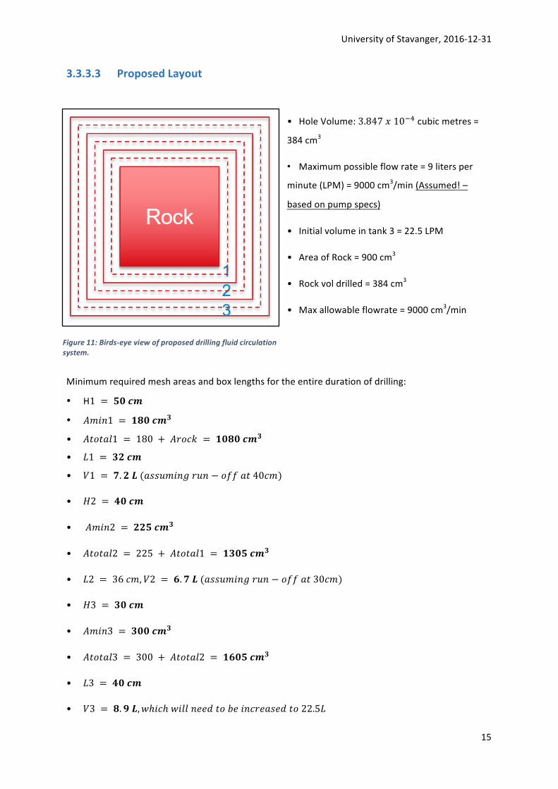
3.3.3.3 ProposedLayout
• HoleVolume:3.847l10üvcubicmetres=
384cm3
• Maximumpossibleflowrate=9litersper
minute(LPM)=9000cm3/min(Assumed!–
basedonpumpspecs)
• Initialvolumeintank3=22.5LPM
• AreaofRock=900cm3
• Rockvoldrilled=384cm3
• Maxallowableflowrate=9000cm3/min
Minimumrequiredmeshareasandboxlengthsfortheentiredurationofdrilling:
• H1 = Öï†|
• °h+ì1 = Ñ¢ï†|{
• °,n,541 = 180 + °7n@= = Ñï¢ï†|{
• à1 = {y†|
• §1 = z. y•(5ddíh+ìA7íì − noo5,40@h)
• ¶2 = õï†|
• °h+ì2 = yyÖ†|{
• °,n,542 = 225 + °,n,541 = Ñ{ïÖ†|{
• à2 = 36@h, §2 = è. z•(5ddíh+ìA7íì − noo5,30@h)
• ¶3 = {ï†|
• °h+ì3 = {ïï†|{
• °,n,543 = 300 + °,n,542 = ÑèïÖ†|{
• à3 = õï†|
• §3 = ¢. ß•, ®ℎ+@ℎ®+44ì66),n*6+ì@765d6),n22.5à
Figure11:Birds-eyeviewofproposeddrillingfluidcirculationsystem.

UniversityofStavanger,2016-12-31
16
3.3.3.4 FlowProfiles
Thedashedlinesresembleadivider,whichwillhaveanoffbottomclearanceof10-15cm.Thishas
beenproposedbytheteamforgoodsolidscontrol.Thedividerswillbesecuredateachcornerofthe
boxtothefloorofthebox.
Figure12:Drillingfluidcirculationsystemflow-pathandproposedlayout
3.3.3.5 Tank3initialMinimumStartupVolume
OneneedstocalculatetheinitialvolumeatcommencementofdrillingthatwillbecontainedinTank
3,whichwearecallingthesuctiontank.
Thefollowingassumptionsaremade:
• Thewellwillbedrilledintwohours(worstcasescenario)
• Themaximumpossibleflowrateis9LPM=150cu.cm/s
• Totalfluidvolumepumpedoverthecourseofdrillingis1080Lifdrillingtakestwohours
Onealsoneedstoknowthe“filluprate”oftank3andunderstandhowmanylitresperminuteare
comingbackfromthewellintotank3.Alsoneedtoknowhowlongitwilltakeforfirstfluidtoflow
backoncedrillingcommences.
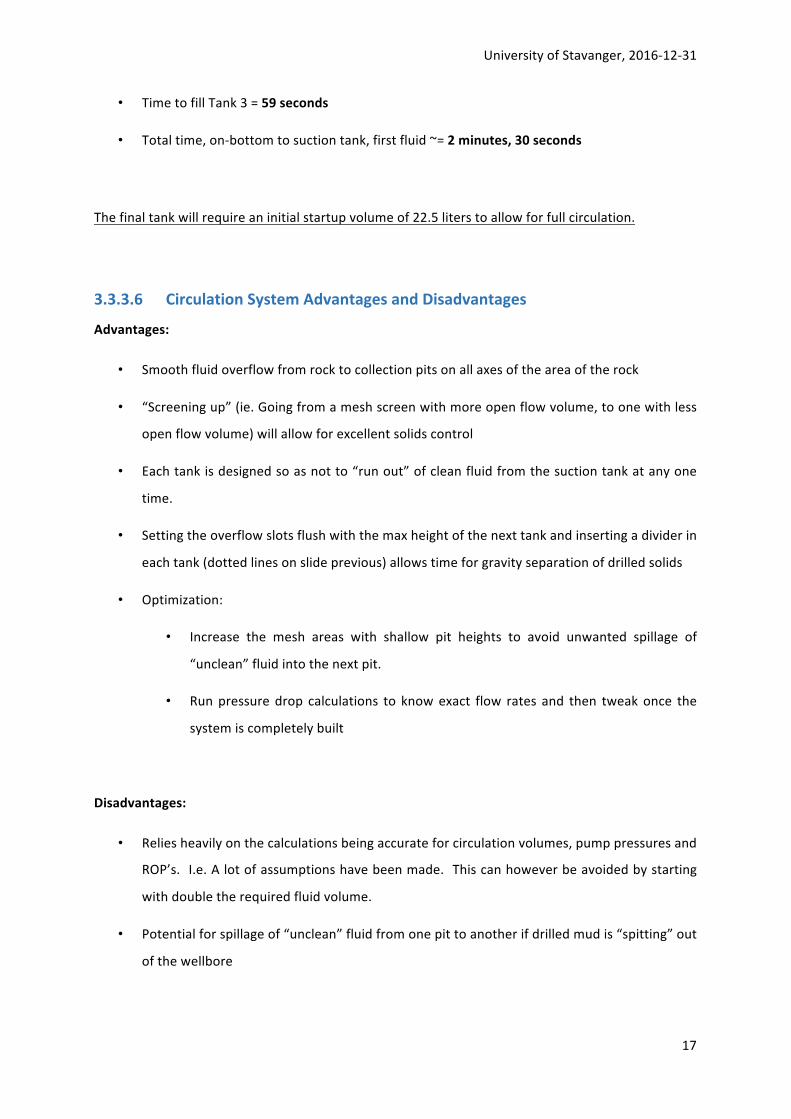
• TimetofillTank1=47seconds
• TimetofillTank2=44seconds
UniversityofStavanger,2016-12-31
17
• TimetofillTank3=59seconds
• Totaltime,on-bottomtosuctiontank,firstfluid~=2minutes,30seconds
Thefinaltankwillrequireaninitialstartupvolumeof22.5literstoallowforfullcirculation.
3.3.3.6 CirculationSystemAdvantagesandDisadvantages
Advantages:
• Smoothfluidoverflowfromrocktocollectionpitsonallaxesoftheareaoftherock
• “Screeningup”(ie.Goingfromameshscreenwithmoreopenflowvolume,toonewithless
openflowvolume)willallowforexcellentsolidscontrol
• Eachtankisdesignedsoasnotto“runout”ofcleanfluidfromthesuctiontankatanyone
time.
• Settingtheoverflowslotsflushwiththemaxheightofthenexttankandinsertingadividerin
eachtank(dottedlinesonslideprevious)allowstimeforgravityseparationofdrilledsolids
• Optimization:
• Increase the mesh areas with shallow pit heights to avoid unwanted spillage of
“unclean”fluidintothenextpit.
• Runpressuredrop calculations to knowexact flow rates and then tweakonce the
systemiscompletelybuilt
Disadvantages:
• Reliesheavilyonthecalculationsbeingaccurateforcirculationvolumes,pumppressuresand
ROP’s.I.e.Alotofassumptionshavebeenmade.Thiscanhoweverbeavoidedbystarting
withdoubletherequiredfluidvolume.
• Potentialforspillageof“unclean”fluidfromonepittoanotherifdrilledmudis“spitting”out
ofthewellbore
UniversityofStavanger,2016-12-31
18
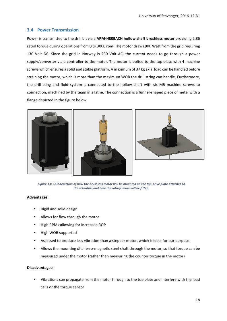
3.4 PowerTransmission
PoweristransmittedtothedrillbitviaaAPM-HE09ACHhollowshaftbrushlessmotorproviding2.86
ratedtorqueduringoperationsfrom0to3000rpm.Themotordraws900Wattfromthegridrequiring
130 Volt DC. Since the grid in Norway is 230 Volt AC, the current needs to go through a power
supply/converterviaacontrollertothemotor.Themotorisboltedtothetopplatewith4machine
screwswhichensuresasolidandstableplatform.Amaximumof37kgaxialloadcanbehandledbefore
strainingthemotor,whichismorethanthemaximumWOBthedrillstringcanhandle.Furthermore,
the drill sting and fluid system is connected to the hollow shaft with six M5 machine screws to
connection,machinedbytheteaminalathe.Theconnectionisafunnel-shapedpieceofmetalwitha
flangedepictedinthefigurebelow.
Advantages:
• Rigidandsoliddesign
• Allowsforflowthroughthemotor
• HighRPMsallowingforincreasedROP
• HighWOBsupported
• Assessedtoproducelessvibrationthanasteppermotor,whichisidealforourpurpose
• Allowsthemountingofaferro-magneticsteelshaftthroughthemotor,sothattorquecanbe
measuredunderthemotor(ratherthanmeasuringthecountertorqueinthemotor)
Disadvantages:
• Vibrationscanpropagatefromthemotorthroughtothetopplateandinterferewiththeload
cellsorthetorquesensor
Figure13:CADdepictionofhowthebrushlessmotorwillbemountedonthetop-driveplateattachedtotheactuatorsandhowtherotaryunionwillbefitted.

UniversityofStavanger,2016-12-31
19
3.5 HoistingSystem
3.5.1 HoistingSystemPrinciples
TheeffectiveROPreliesheavilyonhowmuchWOBwecanapplytotheformation.Sincethereisno
limitthisyearonmaximumWOB,thealuminumdrillstringcriticalbucklingforce(CBF)determines
themaximumWOBourhoistingsystemwillprovide(CBFmax=182Npinned,22Nswaying).Through
continuoustorquemeasurement,anddatacollectionfromtheloadcellsinthez-direction,the
systemisabletooperateclosetothemaximumCBF.Byusingananalogueinfraredheightsensor
(0.2to1.5mdistance),therigisallowedtooperatewithhigherRPMsandROPsinthetop-andmid
sectionoftherock,beforeloweringtheROPintheend-phaseofthedrillingoperation.The
estimatedweightofthemovingplatform,includingthehollowshaftmotor,swivel,topplate,the
drillstring,BHAandsensorsareestimatedtobe25kg,wellbelowthemaximumaxialloadof37kg
thetopdrivemotorcanprovide.
Tocounteractapossibleinclinationofthedrillstring,threeactuators–eachconnectedtothetop-
driveplatethroughtri-axialloadcellssupporting0-100Noneachx-,y-,z-axis,areutilized.Through
initialsystemcalibrationandtestingwithoutapplyingaforceontotheformation,thestrategic
decisioncontrollerestablishesasetofinitialvaluesdefiningaperfectlyleveledtop-plateresembling
averticaldrillstring.Ifanoff-setisdetectedinthex-,y-directions,thereal-timecontrollerwillfeed
theproperactuatorswithcommandstore-establishasituationofforceequilibriumbetweenthe
loadcells,thusallowingtocontinuedrillingwithaverticaldrillstring.Testingwiththecompletedrig
willdeterminewhetherthisoperationcanbedonewhiledrillingorwhetheronewillneedtotripout
ofthewell,adjustandcommencedrilling.Thethreesteppermotors(oneforeachactuator)will
provideenoughtorqueandliftpowertotripinandoutwithhighenoughspeeds.
Figure14:Outlineofthehoistingsystemandasimplifiedsketchshowinghowoff-setdetectionwillcorrectdrill-stringinclination

UniversityofStavanger,2016-12-31
20
3.5.2 HoistingSystemComponents
Thehoistingsystemisrequiredtorespondquicklyandpreciselytoascenariowherethedrillstring
startstodeviatefrombeingcompletelyvertical.Therefore,eachactuatorisequippedwitha
NEMA232,80Asteppermotor,eachwithastepangleof1.8andatorqueof1.236Nmgivingthe
hoistingsystematotaltorqueof3.71Nm.Todecelerateandholdinertialloads,eachsteppermotor
isequippedwithaHucoBrakeFSB015,supportingastatictorqueof1.69Nm(totalof5.07Nm).
Astherocksampletobedrilledhasanestimated
heightof0.6m,thechosenactuatorshaveatravel
lengthof0.9m,allowingforfullypenetratingthe
rocksampleaswellastrippinginandoutofthe
holeifrequired,tolevelthetopplateand
commencedrillingvertically.C-beamLinear
actuatorbundles(1000mm)areused.TwoC-
beamriserplatesareusedtoconnecteachofthe
actuatorstotheloadcellsattachedonthetop-
plate.
TonotonlymeasureWOB-forcesandhookloadinthez-direction,it
wasdecidedtousetri-axialloadcells.TheFNZload-cellsprovidedby
Forsenteksupport0-100Nonallthreeaxes.Theuseofthreeload
cellsthusallowsforatotalof300NintheZ-direction,andsimilarin
thex-andy-direction(theseforcesareestimatedtonotbenearlyas
highasinthez-direction).Withanestimatedmaximumweightof
25kg(approx.245N),thereshouldbenoriskofdamagingtheload
cells.Giventhatthereal-timecontrollersystemneedstohavea
deterministiclatency,andfairlyquickloop-timestobeabletoreact
quickenough,loadcellswithahysteresisof+-0.2%oftherated
Fx
Fy
Fz
Figure15:NEMA23StepperMotor Figure16:HucoBrake(FSB015)withastatictorqueof1.69Nmforeachbrake.
Figure17:C-beamLinearactuatorbundleequippedwithaNEMA23Steppermotor.
Figure18:ForsentekFNZtri-axialloadcell(x,y,z:0-100N).

UniversityofStavanger,2016-12-31
21
output(1.0mV/V)havebeenchosen.Theloadcellsanaloguesignaloutputwillbeconnectedtoan
analogueamplifierandrunthroughanArduinoDue32-bitmicrocontroller(actingasananalogue
digitalconverter)beforeprocessedbythereal-timecontroller.ByusingArduinos,processingisdone
withlowenoughlooptimes,allowingustooperatewithhigherRPMsandROPsduringthedrilling
operation.ThreeArduinoDueswillbeused:oneforthepowertransmissionsystem,oneforthe
hoistingsystemandoneforthepump.
Figure19depictshowtheelectricalsystemwillbeconfiguredforthesteppermotors.
ThethreeHucoBrakes(oneforeachmotor)willalsorequiresimilarelectricalconfigurations.The
ArduinoDuemicrocontrollerswillbepoweredusingaUSB-hub,astheseonlyrequire10Woftotal
powertorun.
Advantages:
• AccurateandpreciseWOB,withafastresponsesystemifneededtochangeWOBrapidly
• Systemcanhandleandcorrectaninclinationofthedrillstringthusensuringverticaldrilling
• AllowsforhighRPMandROPs
• Fastresponsetimestoreal-timecontrollerreducingriskoftwist-offscenario
• Combinedwiththeferro-magnetictorquesensor,thedesignallowsdrillingoperationsfully
exploitingthecapabilitiesoftherig,ratherthanoperatingwithveryhighsafetyfactorsdueto
slowresponsetimeandlongloopdurations
• Singlecomponentseasytoassembleandconnect,chosencomponentsalsoallowfortweaking
ifdesign-alterationsarerequired
• Cantripinandoutofthewellifthisisrequiredtobalancethetopplate
Figure19:Electricalconfigurationforthethreesteppermotorscontrollingtheactuators.

UniversityofStavanger,2016-12-31
22
Disadvantages:
• Advancedcontrolsystemandprogramming
• Duetohighsamplingrates,somecomponentsmightbeexposedtodamageifamajorleakage
inthecirculationsystemoccurs.
3.6 ConstructionofFramework
Toensurestabilityofthemobilerig,high-gradealuminiumstrut
profilesaretobeused.BoschRexrothStrutProfiles90x90L/
45x45Lareevaluatedtogiveusthebestoverallstability,
defendingthehighcostofthesecomponents.90x90LStrut
Profileswillbeusedinthelowersectionsoftherigsupportingthe
overlyingconstruction.45x45Lstrutprofileswillbeusedinthe
uppersectionoftherigandtoconnecttablestoeachside,in
whichthepump,computer(inclmonitors)andelectricalcontrol
systemwillbemountedon.
With90x90and45x45brackets,andlockable45x45joints,theconstructionwillnotbeexposedto
creepovertime,whichoftencanbeseeninsmall-scalerigsandbuildswhereunder-dimensioned
strutprofilesareutilizedwithoutproperjointsconnectingthem.
Themainconstructionrigwillbemountedonlifting
wheels,alsoprovidedbyBoschRexroth
(3842547890).Theyallowformovementoftherig,
andcanbede-attachedatthescenewherethe
drillingwillbeconductedtoavoidmovementand
instabilitywhendrilling.Acrylicplasticsheetswill
beboughtatBiltema,andmountingtablesare
providedbytheUniversity.Theacrylicplasticsheets
willallowforsafedrilling,infrontofanaudience,
andwillalsoprotecttheelectricalcomponents
wiredandconnectedoutsideoftherig.
Figure20:Outlineoftheframeworkofthedrillingmachine.
Figure21:Bracketsandlockablejointswillpreventtheconstructionfromcreeping.

UniversityofStavanger,2016-12-31
23
3.7 TorqueSensing
3.7.1 DesignPrinciples
Thetorquesensorisadeviceformeasuringandrecordingthetorqueonarotatingsystem.The
sensorwillnotmeasurethetorquecomingfromthemotor,butonlytheactualDP-torque.This
allowsustooperateclosetomaximummechanicalpropertiesofthedrillstring.
Sincethetorquesensorcanonlymeasuretorqueinaferro-magneticshaft,wewillinstalla
ferromagneticDPwithanequalODandIDasouraluminumdrillpipe.Thiswillbeattachedbetween
thehollowshaftmotorandtheAlshaft.ThetorquesensorprovidedbyTAMwillprovideadigital
samplingrateof2000Hz(i.e.2000samples/second).Thisconfigurationwillallowustooperatewith
RPMs>300revolutionsperminuteofthedrillstring.Thetorquesensorisdeliveredwithsoftware
thatcanbeintegratedintoMatlabandMatlabSimulink,thusmakingassemblyandintegrationinto
thecontrolsystemsimple.
Theferromagneticsteelshaftwillbemadeinalathe,whereoneendhasaflangewhichwillbe
attachedtothemotorshaftwithsixscrews,withasealbetweentheflangeandtheshaft.Thetorque
sensorwillbeinstalledasshowninfigure22.AstheODandIDwillbeequaltothatoftheDP,and
Figure22:TorqueSensorprovidedbyTorqueandMoreGMBH,modifiedtoprovideasamplingrateof2000HzandsupportingintegrationintoMatlabandMatlabSimulink.

UniversityofStavanger,2016-12-31
24
thetorquesensorisfittedtoourintendedferromagneticshaft,thedistancebetweenthesteelshaft
andthetorquesensorwillbelessthan2mm(whichisaworkingrequirementforthetorquesensor).
3.7.2 SystemAdvantagesandDisadvantages
Advantages:
• Out-of-the-boxmeasurementsimmediately
• Non-Contact,allowingforsomevibrationinthedrillstringwithoutdamagingthetorquesensor
• WorksonanyFerromagneticobject/shaftmakingthesensorsuitabletomosttorque-
measurement-purposes
• Noshaftmagnetizationrequired
• Anyshaftsize(>5mmdiameter),noupperlimit
• Reliableperformance
• Notaffectedbyover-load
• Notdamagedbymagneticstrayfield
• Insensitivetowater,oilanddust
• Insensitivetoair-gapchanges
• Insensitivetoshaftspeed
• +5Voltanaloguesignaloutput
• USBserialdigitalcommunicationwithPC
• Automaticandmanualinitialization
• Bi-directionalmeasurementrange
• Built-indataloggerandsignalfilter
• Verywiderangeofmaterialwhereitcanbeused
Disadvantages:
• Samplingfrequencyislimitedto10000Hzrawdata,2000Hzafterfiltering(toensureahigh
enoughsignaloutputtoovercomesignalnoise)
• RPMlimitations
• Equipmentisexpensive,evenwiththespecialpriceTAMGMBHofferedtotheUniversity,and
maybetooexpensiveforlow-costrigs.Itdoeshoweverfitwellintoourbudget,sinceaccurate
torquesensingisoneofourhighestprioritiestoavoidatwistoffsituation

UniversityofStavanger,2016-12-31
25
3.8 PressureSensing
Asseeninsection3.1.1Pump,basedonpreliminarycalculationsandassumptions,thepumpshould
beabletooperatewithapressureheadofatleast2.26bar.Withtheproposeddesign,thepumphas
acutoutpressureof3.1bar,andinordertonotsustaindamagetothepumpandotherequipment,
itisthereforeanecessitytoincludeapressuresensorinthecontrolsystem.Forthispurpose,we
plantouseaGemsSensorsPressureSensorthatmeasures0-10bar.
Thepressuresensorhasan
analogueoutputof4-20mAand
runsonasupplyvoltageof10-
30Vdc.Althoughwedonot
plantooperatewithdifferent
pressuresandflowvelocities,
thepressuresensorisa
necessityininitialcalibration
andthetestoffphasebefore
drillingcanbegin,todetectany
leakorsystemfaultthatcan
effectthedrillingoperation.
Advantages:
• Easytofitintotherigdesignandoperate
• Canuseexistingmicrocontrollers(ArduinoDue)todoanaloguedigitalconvertingoftheoutput
signal
• Highaccuracyandresponsetime
• GoodexperienceinpreviousUiS-projects
• Operatesatmosttemperatureranges
Disadvantages:
• Expensiveduetoitshighaccuracyandperformance
• Signalneedstobeconverted
Figure23:TheGemsanaloguepressuresensorhasaresponsetimeof1ms,andanaccuracyofwithin0.25%.

UniversityofStavanger,2016-12-31
26
3.9 AnalogueInfraredElevationSensing
IntheDrillbotics2016competition,theUiS-righadnocapabilitytodeterminetheelevationofthebit
accuratelyatalltimes.ToallowforhigherROPduringdrilling,andasatooltoincreaseaccuracyin
calibrationanddrillofftesting,ananalogueinfraredheightsensorisproposedinourphase1design.
TheSharpdistancesensor(GP2Y0A02YK0F)providesdistancemeasuringbetween20-150cmwhich
ishighlyacceptableforthedesignandcontrolsystem.Therockistobedrilled0.6m,andthe
additionaldistanceallowsforaccuracyiftrippinginandoutofthewell.Thedistancesensorwillbe
fittedbeneaththetopplate(wherethetopdriveismounted),andwillreceiveareflectionoffofthe
platethatlaysontopoftherocksampletopreventspillage.Thedistancesensorhasananalogue
outputvoltageof0.4to2.45Vandshouldnotrequireanadditionalamplifier.
Advantages:
• Easytofit
• Infraredsensingischeapcomparedtoalaserandprovidesenoughaccuracy
• Allowsforelevationmeasurementsthroughouttheentiredrillingoperation
• IntegrateswellwiththeArduinomicrocontrollers
Disadvantages:
• Reflectorcanbesoiledbydrillingfluid(WBMorOBM)ifaleakoccurs,possiblyrenderingthe
sensorinaccurateintheend-phaseofthedrilling
Figure24:Depictionoftheproposedsharpdistancesensor.Thesensorwillneedanamplifier,astheoutputvoltagewilldecreaseasthedistanceincreases.
UniversityofStavanger,2016-12-31
27
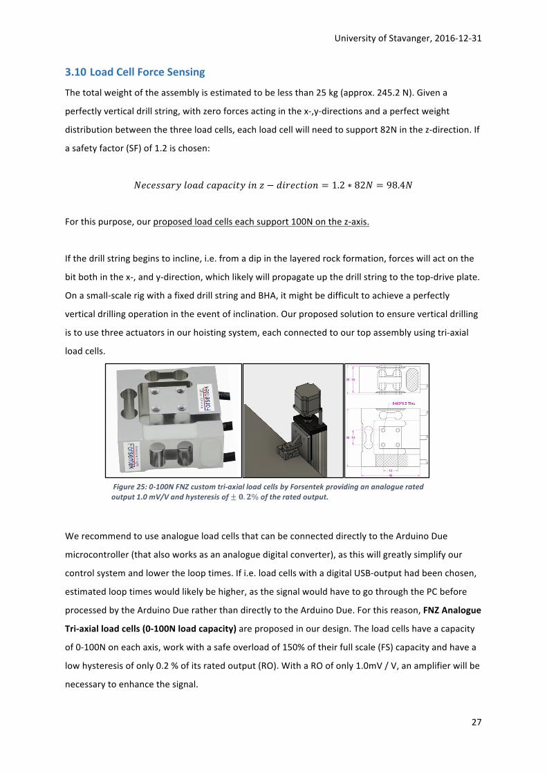
3.10 LoadCellForceSensingThetotalweightoftheassemblyisestimatedtobelessthan25kg(approx.245.2N).Givena
perfectlyverticaldrillstring,withzeroforcesactinginthex-,y-directionsandaperfectweight
distributionbetweenthethreeloadcells,eachloadcellwillneedtosupport82Ninthez-direction.If
asafetyfactor(SF)of1.2ischosen:
x6@6dd5784n5)@5©5@+,8+ìá − )+76@,+nì = 1.2 ∗ 82x = 98.4x
Forthispurpose,ourproposedloadcellseachsupport100Nonthez-axis.
Ifthedrillstringbeginstoincline,i.e.fromadipinthelayeredrockformation,forceswillactonthe
bitbothinthex-,andy-direction,whichlikelywillpropagateupthedrillstringtothetop-driveplate.
Onasmall-scalerigwithafixeddrillstringandBHA,itmightbedifficulttoachieveaperfectly
verticaldrillingoperationintheeventofinclination.Ourproposedsolutiontoensureverticaldrilling
istousethreeactuatorsinourhoistingsystem,eachconnectedtoourtopassemblyusingtri-axial
loadcells.
WerecommendtouseanalogueloadcellsthatcanbeconnecteddirectlytotheArduinoDue
microcontroller(thatalsoworksasananaloguedigitalconverter),asthiswillgreatlysimplifyour
controlsystemandlowerthelooptimes.Ifi.e.loadcellswithadigitalUSB-outputhadbeenchosen,
estimatedlooptimeswouldlikelybehigher,asthesignalwouldhavetogothroughthePCbefore
processedbytheArduinoDueratherthandirectlytotheArduinoDue.Forthisreason,FNZAnalogue
Tri-axialloadcells(0-100Nloadcapacity)areproposedinourdesign.Theloadcellshaveacapacity
of0-100Noneachaxis,workwithasafeoverloadof150%oftheirfullscale(FS)capacityandhavea
lowhysteresisofonly0.2%ofitsratedoutput(RO).WithaROofonly1.0mV/V,anamplifierwillbe
necessarytoenhancethesignal.
Figure25:0-100NFNZcustomtri-axialloadcellsbyForsentekprovidingananalogueratedoutput1.0mV/Vandhysteresisof±ï. y%oftheratedoutput.

UniversityofStavanger,2016-12-31
28
Advantages:
• Tri-axialforcemeasurementshighlyincreaseouroperationalcapability
• Asufficientlyhighloadcapacityoneachaxisandasafeoverloadof150%ofFSreducesrisk
ofdamagetothesensors
• AnalogueconnectivitylowerslooptimesastheycanbeconnecteddirectlytotheArduino
Due
• Lowhysteresisensuresaccuracyinforcemeasurements
• Lowprofileandweight
• Easytoinstallbetweensteel-plateandactuators
• FNZloadcellcheapcomparedtosimilarproducts
Disadvantages:
• Multi-axisloadcellsareexpensivecomparedtosingle-point
o Priceallowsforlessexperimentationwithhighloadsapplied
• Ananaloguesignal,beingtransmittedoverlongdistances,isexposedtonoiseaddingup–
degradingthesignal-to-noiseratio
Solution:Tocircumventreceivingatoolowsignal-to-noiseratio(SNR),weintendtopositionthe
ArduinoDuesonthetopplate,nexttothemotor,inasealedcontainer.Thisreducesthetravel
lengthoftheanaloguesignalfromapproximately2.5mtolessthan0.5m,whichgreatlyshould
enhanceourSNR

UniversityofStavanger,2016-12-31
29
4. SystemCalibrationandDetectionofDrillingDeteriorationAsdiscussedinsection3RigDesign,itisvitaltoknowtheindividualcomponents´andthesystem
responsetime,sothatrapidchangesinthedrillingconditionscanbedetectedandhandledwithout
riskingtwistoffoftheDPordamagetothedrillingmachine.Theresponsetimeofthesystem
dependsontheloopdurationofthecontrollerbutitalsodependsonitsmechanicalinertiaand
friction.Itisthereforevitaltocalibratetheactualresponseofthesystemtodifferentconditions.
4.1CalibrationinSteadyStateConditions
Thestrategicdecisioncontrollerisnotrequiredtobeasfastasthereal-timecontrollers,sothiscanbe
non-deterministicwithvaryinglatencies.ThecalibrationneedstoprovidevaluesforzeroWOBapplied
totheformation,pumppressure,torque,drillstringverticalityandhook-load.
4.1.1SteadyStatePumpPressure(sameasDrillbotics2016,Universityof
Stavanger)7
AstheprovidedpressurebythecirculatingsystemdoesnotprovideacontributiontotheROP,but
simplyremovescuttingsandhelppreventastuck-pipesituation,wewillnotcontrolthepumpmotor
speed.Thepumpspeedvariesasafunctionofthepumppressure.Hence,ifthecirculation
conditionschange,thepumppressurewillchangeandsowillthemotorspeeduntilonereachesa
newsteadystatecondition.Therearetwopossiblereasonsforthechangesincirculationconditions.
Thefirstoneisachangeofthehydrostaticpressureatthepumpoutlet.Thehighestelevationpoint
ofthehoseconnectedtotheswivelchangesasthetop-driveisraisedorlowered.Thesecondfactor
influencingthepressurelossisthetransportofcuttingsoutoftheborehole.
Wedonotreallyneedtoknowtheexactpumppressureaslongastheconditionsarenormal.Butwe
doneedtoknowwhenthepumppressurestartstogetabnormal,suchasifthereisapack-off
(overpressure)orifthedrill-pipesarebroken(under-pressure).Forthatreason,weplantocalibrate
the
7DrillBotics2016-UiS-PhaseI-v0.5
Figure26:Illustrationofhowcalibrationwillbeconducted;acylinderwillbeplacedinsidethewatercontainerandpumppressurewillberecordedatdifferentbitdepths.
UniversityofStavanger,2016-12-31
30
expectedrangeofnormalpressures.Theprocedurewillconsistinputtingacylinderinsidethewater
containerandrecordthepumppressureatdifferentbitdepths.Thenwewillfillthecylinderwith
sandandwewillrepeattheprocedureatdifferentspeedsandrecordthecorrespondingpressure
variations(seeFigure30).Afterseveralexperiments,weshouldhavenormalpumppressure
variationsasafunctionofthetop-driveelevationwhichcanthenbeusedtoautomaticallydetect
obstructionsordrill-pipewashouts.
4.1.2SteadyStateTorqueCalibration
Aswethisyearhavedecidedonusinganon-contactferromagnetictorque
sensor,ratherthanhavingthetop-drivemotorismountedintoafree
rotatinggimbalwhichhasanarmthatpressesagainsttwoloadcells,steady
statetorquewillnotbeaffectedbyfrictioninthebearingsofpower
transmissionshaft.
Thissystemdesignallowsustocalibratetorquemeasurement,byhavingthe
motorcontrollermaintainingdifferenttorquesandspeedswithoutapplying
WOBontotheformation.Inthatwaywewillobtainaconversiontableof
themeasuredtorqueasafunctionofthepowertransmissionspeed,from
whichtherealtimecontrollercaninterpolateduringtheactualdrilling
operation.
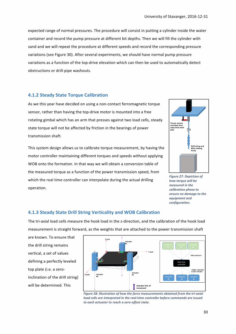
4.1.3SteadyStateDrillStringVerticalityandWOBCalibration
Thetri-axialloadcellsmeasurethehookloadinthez-direction,andthecalibrationofthehookload
measurementisstraightforward,astheweightsthatareattachedtothepowertransmissionshaft
areknown.Toensurethat
thedrillstringremains
vertical,asetofvalues
definingaperfectlyleveled
topplate(i.e.azero-
inclinationofthedrillstring)
willbedetermined.This
Figure27:Depictionofhowtorquewillbemeasuredinthecalibrationphasetoensurenodamagetotheequipmentandconfiguration.
Figure28:Illustrationofhowtheforcemeasurementsobtainedfromthetri-axialloadcellsareinterpretedinthereal-timecontrollerbeforecommandsareissuedtoeachactuatortoreachazero-offsetstate.

UniversityofStavanger,2016-12-31
31
shouldbedonewiththepowertransmissionsystemoperatingatdifferenttorquesandspeeds,as
rotationfromthepowertransmissionshaftlikelywillexertforcesinthex-andy-directions.By
measuringtheseforceswhilemaintainingrotation,onecandeterminezerooff-setvalues,thus
allowingoff-setdetectionwhiledrillingthroughtherocksamplethatcanbecompensatedfor.
4.2 CalibrationinTransientConditionsItisimportanttoknowthedynamicresponseofthesystematvariousrotationalandaxial
speeds.HowweplantoobtainthisinformationwillbeoutlinedintheDrillboticsJanuaryUpdate
2017.
4.3 DetectionofaDeteriorationinDrillingConditions(sameasDrillbotics2016,
UniversityofStavanger)8
Inidealconditions,theROPvarieslinearlywithWOBandRPM.However,ifthemaximumdepthof
cutisreached,theROPwillnotincreasewhenaddingmoreweight:thereisnotanymorealinear
response.Similarly,iftherearefineparticlesaccumulatingaroundthecutters,thebitwillnotwork
ideallyandtheresponsetochangesinRPMorWOBwillnotbelinear.Finally,iftherearevibrations
atthebit,theenergyprovidedtothebitwillnotbesolelyusedtodrilltheboreholeandtherefore
thelinearitydependenceoftheROPtoWOBandRPMwillnotberespected.Thepointbywhichthe
linearityislost,isoftencalledthefounderpoint.
Sothenon-linearityoftheROPasafunctionofthevariationsofWOBandRPMcanbeagoodindication
thatthedrillingconditionsarenotoptimal.Forthatreason,automaticsweepsofWOBandautomatic
sweepsofRPMwillbeperformedwhentheROPseemstobestable(ifitisnotstable,thenitishard
toconcludeanything).Incaseofnon-linearbehavior,thedrillingparameterswillbechangedtoensure
thatthebitworksingoodconditions.
8DrillBotics2016-UiS-PhaseI-v0.5
Figure29:Definitionofthefounderpoint,sothatadeteriorationintheDrillingconditionsmaybedetected.

UniversityofStavanger,2016-12-31
32
5. ControlStrategies:DownholeDrillingProblems
5.1LiteratureReview
Oneofthekeycriteriaofthisprojectisthatdrillingshouldbecompleteautomated.Thismeanswe
havewhatisineffecta“pluginandplay”systemwhichdrillsthewelltoplan.Thesystem,asapart
oftheautomationprocess,needstobeabletodiagnoseanumberoflikelydrillingproblems,andbe
abletorespondaccordinglytokeepdrillingontrackandwithoutanydamagetothedrillstring,orrig
components.Thereareanumberofdrillingrelatedissueswhichmaybeencounteredinthisproject,
whichhavebeenoutlinedbelow.
Note:Nomentionwillbemadeatpresentontheprogramming language,oranyoftheupperand
lower limitsondrillingparameterswhichwillbeusedtobe indicativeofdownhole issues. Further
discussionaroundtheseaspectsof thecontrol systemsandprogrammingdesignwill follow indue
course.Thissectionaimsonlytoprovideanoverviewofthemostlikelydrillingscenariosandhowone
mightreactinareal-lifesituation.Commentshavebeenmadewhereappropriateonhowtheseissues
maybeapplicabletotheDrillboticsRig.
5.2 NormalDrillingState(sameasinDrillbotics2016,UniversityofStavanger)9
5.2.1 BottomHoleTagging
Inaninitialunspecifiedstate,thesystemdoesnotknowwhetheritisonbottomornotanditdoes
notknowwhereisthetopoftheblock.Forthatreason,itstartstoraisetheblockforaminimum
distanceanduntilthehookloadhasstabilizedinordertoensurethatitisoffbottom.Thenitmoves
downwarduntilthehookloadstartstodecrease:thiselevationisrecordedasthetopoftheblock.
Duringthisoperation,thepumpandthetop-driveareoff.
Comment:IntheDrillbotics2017-design,ananalogueheightsensorwillbeusedinsteadfor
continuousmeasurementofdrillbitposition.ThisisdonetoallowforhigherROPsinthetop-and
mid-sectionoftherock(byknownthebitelevationrelativetotherock)andfordisplaypurposes.
5.2.2 OffBottomCalibration
Thisprocedureisusedwhenthesystemisuncelebratedbutaftertaggingthebottomhole.With
rotationandpumpingoff,thecontrolsystemraisesthedrill-stringforaminimumdistancetoensure
9DrillBotics2016-UiS-PhaseI-v0.5

UniversityofStavanger,2016-12-31
33
thatthebitisoffbottom.Thenitstartsthepumpingandwaituntilthepressurehasstabilized:this
willbethereferencepressure.Afterward,itstartstherotationbyincrementalsteps.Foreachstep,
thesystemwaitsforastabletorqueandrecordstheperiodandamplitudeoftheoscillations
generatedbytherotationalspeedstepchangesinordertogatherinformationaboutthenatural
resonancefrequenciesofthedrill-string.Theoffbottomtopofstringforceisalsorecordedasa
referencevalue.
5.2.3 ResumeDrilling
Whenthetopoftherockisknownandthesystemhasbeencalibrated,drillingcanstart.Ifthebitis
onbottom,thedrill-stringisraisedforashortdistance.Ifthereisnocirculation,thenthepumpis
started.Iftherotationisoff,thetop-driveisrampeduptoamiddlerangespeedthatdoesnot
correspondtoanaturalresonancefrequencyofthedrill-string.Thenthedrill-stringisloweredtothe
lastknowntopholeataspeedthatiscompatiblewiththereactiontimeofthecontrolsystemfor
handlinglargevariationofformationstrength.
5.2.4 ManagementofROPinanUnknownFormation
Whenstartingdrillinginanunknownformation,theWOBisincreasedaslinearlyaspossiblewhile
theROPisrecorded.However,theWOBshallneverexceedthemaximumallowableWOBtohandle
rapidchangeofformationstrength.ThelinearityoftheROPvsWOBcurveisanalysedtodetermine
theformationstrength.ThentheRPMischangedtoavaluethatincreasesROP,yetissafefor
handlingsuddenstick-slipconditions.
5.2.5 ManagementofROPinaKnownFormation
Whentheformationstrengthhasbeenestimated,theWOBislinearlyincreasedandthendecreased
witharelativelysmallvariationtoverifythattheROPstillvarylinearlywiththeWOB.Ifthelinearity
factorhaschanged,thenitisanewformation.Ifthevariationisnotlinear,thenthebitdoesnot
workingoodconditions.Alternatively,theRPMislinearlyincreasedandthendecreasedwitha
relativelysmallvariationtoverifythattheROPstillvarylinearlywiththeRPM.Ifthevariationisnot
linear,thenthebitdoesnotworkingoodconditions.
5.2.6 ManagementofDrillingParametersBetweenSoftandHardFormations
IftheROPreducesdrastically,wearedrillingfromasofttoahardformationandthereisariskfor
drill-stringvibrations.TheWOBandtheRPMarechangedtominimizetheriskofdrill-string

UniversityofStavanger,2016-12-31
34
vibrations.WhentheROPhasstabilized,wehavepassedthetransitionzoneandanewformation
canbeinvestigated.
5.2.7 ManagementofDrillingParametersBetweenHardandSoftFormations
IftheROPincreases,wearedrillingfromahardtosoftformationandthereisariskfordrill-string
vibrations.TheWOBandtheRPMarechangedtominimizetheriskofdrill-stringvibrations.When
theROPhasstabilized,wehavepassedthetransitionzoneandanewformationcanbeinvestigated
asexplainedin6.1.4.
5.2.8 ManagementofanIncliningDrillString
Comment:IntheDrillbotics2017-design,thissectionisnewasweintendtouseathree-actuator
hoistingsystemandtri-axialloadcellstohandleaninclinationofthedrillstring.Thesystemwill,
dependingonsuccessintesting,maintaintheRPMbutthesystemwilltripoutofthewell.The
actuatorswillbecorrectedinaccordancewitheachother,toachieveastateofalineartopplate
(fullyhorizontal)resemblingacompletelyverticaldrillstring.TheRPMwillbeincreasedtoahigher
RPMthanthatwhichleadtoaninclination,WOBwillbemaintained.Onewillattempttotripback
intothewell,ifdrillingcancontinuewithoutarepeatedinclinationofthedrillstring,drilling
continues.IftheDPagainbeginstoincline,resettoazero-offsetinthetopplateposition(vertical
drillstring)andattemptwithahigherRPMandhigherWOB.Testingwilldeterminehowthefinal
commandwillbe.
5.2.9 EndofDrilling
Comment:Byusingtheanalogueheightsensor,theROPwillbeloweredforthelast0.03m(3cm)of
therocksample,i.e.a57cmhasbeendrilledand3cmremains.TheROPwillbeheldconstantuntil
reaching0.6mbitdepthintotherocksamplebeforetherigwilltripoutofthewellandWOBand
RPMwillbeadjustedto0.

UniversityofStavanger,2016-12-31
35
5.3 DeterioratedDrillingState(sameasinDrillbotics2016,Universityof
Stavanger)10
5.3.1 ManagementofPoorROPPerformance
IfthevariationofROPasafunctionofWOBorRPMisnotlinearthenthebitisnotworkingin
optimalconditions.Thatcanbeduetobottomholeballing,bitdullingorvibrations(Dupriest&
Koederitz,2005).IfitwastheWOBthatcausedthenon-linearity,thentheWOBisdecreasedlinearly
untilthelinearityconditionisreached.IfitwastheRPM,thentop-drivespeedisdecreasedlinearly
untilthelinearityconditionissatisfied.
5.3.2 ManagementofDrillString-vibrations
Ifthetorquestartstofluctuateabovereasonablemargins,thedrill-stringispickedoffbottom.Ifthe
oscillations do not stop after a short moment, the top-drive rotation is ramped down to 0. The
combinationofWOBandRPMthatcausedthevibrationisrecordedforthecurrentformationrock
andwillnotbeusedanymoreuntilanewformationrockisdrilled.AnewcombinationofWOB/RPM
ischosenamongstthosethatarepossibleanddrillingisresumed.
5.4 CatastrophicDrillingState
5.4.1 StuckPipe–DifferentialSticking
Problemdefinition
The drill string becomes stuck due to a high differential pressure between the drill string and the
formation.Thinkoftheboreholeasavacuumcleaner,andthedrillpipebeingsuckedintoit.
Diagnostics
UsuallyasharporgradualdropinROPcombinedwithaproportionalincreaseintorque.Thisismost
clearlyseenwhenrotatingthestringoff-bottom,whereatorqueincreaseisindicativeofdifferential
sticking.CuttingsizeswillalsovaryandSPPshouldincrease.
Solutions
Inourcase,thisishighlyunlikelytooccur,ifevenimpossible.
10DrillBotics2016-UiS-PhaseI-v0.5

UniversityofStavanger,2016-12-31
36
5.4.2 StuckPipe–KeySeating
Problemdefinition
Thedrillstringbecomesstuckduetoastringbucklingcreatingsomethingofakeyholemicro-borehole
adjacenttotheactualborehole.Thiscausessectionsofthepipetobecomeimmobileandisusually
causedbytoomuchWOBorpoordirectionalcontrol
Diagnostics
Immobiledrillstring.SteepdropinROP,combinedwithahightorqueincrease.Needtobecareful
hereaspipe-whirlcaneasilyfollow.
Solutions
This can bemitigated by knowing definitively themaximumbuckling force, applying a SF and not
exceedingthisvalue.
Determine the stuck point of the drill pipe, by converting the string elongation to stuck point
downhole,proceedtopulltomaximumallowableoverpullandattempttoestablishstringrotation.If
unsuccessful,proceedtojar,butdoNOTdosowithstringrotation.Pumpingalubricantdownhole
canalsoassistwithfreeingthepipe,sincethecoefficientoffrictionisreduced.
5.4.3 StuckPipe–Pack-off
Problemdefinition
Thedrillstringbecomesstuckduetopoorboreholequalityeffectivelyblockingupthehole.Whether
thisisdoneatsomepointuptheholeordownattheBHAlevel,itisusuallythecuttingsfallingback
downthatcausethis.
Diagnostics
Nocirculationislikelytobepossible,andtherewillbeasevereincreaseinSPP.Rotationislikelyto
bedifficultandhightorquewillbeagoodindicationofthis
Solutions
DONOT JAR INTOTIGHTHOLE. Attempt topickupoff bottomand circulate clean. Important to
establishifpipemovementispossibleupordown.Fromhere,itisusuallyadvisabletoalterthefluid
propertiestoremovethecuttings.High-viscositysweepscanbehelpfulhere,allthewhileattempting
torestorerotationandcirculation.JarinthedirectionthepipeisNOTstuck.

UniversityofStavanger,2016-12-31
37
5.4.4 DrillingFluids–BitBalling
Problemdefinition
Theblockingofdrillbitnozzlesandgradualcollectionofmud/rockdepositsonthedrillbitblades,
makingdrillingimpossible.
Diagnostics
Sharp increase inSPP,withadrop in torquecanbeseen. Lookout for largecollectionsofgumbo
comingovertheshakers. Mudparametersalmostguaranteedtobeoutofspec. Verycommonin
shalyformationswherenoshaleinhibitorisused(KCl,PAC,KOH-etc.)
Solutions
Inalmostallcasesthebitneedstobepulledandcleaned.Mitigatingactionscanbetakeninourcase.
Since there is every possibility of encountering a swelling clay, ~3-4% KCl should be added to the
systemifaWBMisused.UsingOBMwilllikelyeliminatethisproblemaltogether.
Whencomingbacktobottominanysituationoncedrillinghascommenced,lowWOB,highRPMand
fulldrillingflowrateneedtobeused.
We’llneedtoprogramthesystemtomakeawipertrip(non-rotationaltriptosurfaceandback)every
x-millimetreswithnoflow–essentialforgoodholecleaning.
5.4.5 DrillingFluids–ProgressiveGels
Problemdefinition
The long-term increase inmudPVasa resultofdrilledsolidsbecomingcolloidaloveranextended
periodoftime.MorecommoninWBM.
Diagnostics
AnydecentMudManwillbeabletospotthis,sincehis10and30mingelrheologytestsshouldpick
upthefactthatPVisrising.Ontherigfloor,thedrillerwillseeagradualSPPincreaseandoveralong
period,themudwillstarttolooklikeathickcustard.
Solutions
Decentshakersandacentrifugeusuallysolvethisproblembeforehand.Dumpingadilutingisthemost
immediatesolutionafterthefact.Inourcase,theuseofameshscreenwillbecriticaltoensuringtiny

UniversityofStavanger,2016-12-31
38
drilledsolidstonotbecomecolloidaltooearly.Attachingaconventionalkitchenfilteraroundthefluid
collectionbucketcanhelpwiththis,combinedwithatieredbucketcollection/separationsystem.
5.4.6 Drillstring–Stick/Slip
Problemdefinition
Thestickingof thedrillbit followedby the release fromrock“slipping”once the torquereachesa
certainpoint.Thisoccurserraticallywhendrillingcertainrockswithcertainparameters.
Diagnostics
TypicallyoccurswhendrillingsoftrockwithahighWOBandlowRPM.Thedepthofcutwillincrease
(inlayman'sterms,thismeanthebitistakingabiggerbite)andthetorsionalforceslikelytoincrease.
Solutions
Whenthesediagnosticsarespotted,back-offWOBsignificantly,keepRPMsteady.Ifnochange,back
offRPM.Pickupoffbottom,gobackdrillingandbedthebitwithaverylowWOBandRPM,fullflow
rate.Graduallystageupparameters.
5.4.7 Drillstring–Twist-off
Problemdefinition
Acompleteshearingofthedrillpipeatsomepointalongthestringcausedbyexcessivestringtorque.
This iswhathappenswhen stick-slip isn’t broughtunder control, orwhen thedriller is notpaying
attention.
Diagnostics
Likelywhenstick-slipisbecomingaproblem.TypicallyoccurswhendrillingsoftrockwithahighWOB
andlowRPM.Thedepthofcutwillincrease(inlayman'sterms,thismeanthebitistakingabigger
bitethanusual)andthetorsionalforceslikelytoincrease.
Solutions
Fishing!
Whenthesediagnosticsarespotted,back-offWOBsignificantly,keepRPMsteady.Ifnochange,back
offRPM.Pickupoffbottom,gobackdrillingandbedthebitwithaverylowWOBandRPM,fullflow
rate.Graduallystageupparameters.

UniversityofStavanger,2016-12-31
39
6. DatahandlingandDisplay(sameasDrillbotics2016,Universityof
Stavanger)11
Lastyear’sdesigniskeptfordatahandlinganddisplay.
Thecontrolloopdurationshallbeasshortaspossibleinordertohavethebestpossiblechancesto
control,intime,quicktransitions,likewhenthebitstopsrotatinginastick-slipsituationorwhen
reachingahardformationafterdrillinginasoftone.TheOmronPLChasacommonprocessingtime
of0.4msand,intheworstcase,instructionexecutiontimeis0.41μs.Table1showsthenumberof
PLCinstructionsthatcanbeusedfordifferentPLCloopdurations.
Figure30:Depictionofthe#ofinstructionsthatcanbecarriedoutwithvariousloopdurations.
Astheloopdurationshouldbekeptbelow20ms,andifpossiblecloserto10ms,thePLCprogram
shouldnotexceed3000to4000instructions.Yetthereisaneedtoperformrelativelyheavy
computationslikedrill-stringvibrationcalculations.Sothemostcomplexcalculationsshallbe
performedonthePCside.ButthePCisnotadeterministicmachineandresponsetimecannotbe
guaranteed.TodealwiththevariablelatencyproblemofthecommunicationbetweenthePCand
thePLC,itisproposedtoprecompute,onthePCside,look-uptablesthatarevalidforawiderange
ofparametersandletthePLCinterpolatewithintheselook-uptablesofthevaluesthatareneeded
tocontrolthedrillingprocess.Inthatway,wecankeeptheprogramexecutiononthePCtobenon-
deterministic,whilethePLCprogramcanbekeptasshortaspossibletominimizetheloopduration.
Asimilarmethodhasbeendescribedin(Cayeux,2012).
11DrillBotics2016-UiS-PhaseI-v0.5

UniversityofStavanger,2016-12-31
40
Figure31:Illustrationofhowthedatahandlingisperformedinthehierarchicalcontrolsystem
Themodelsusedtogeneratethelook-uptableshavetobecalibratedwiththeactualrecorded
values.Forthatreasonacalibrationprocessmonitorsthesensorvaluesandextractcalibration
parametersthatareusedwhilecomputingthelook-uptables.
ThesensorvaluesacquiredbythePLCarepushedtothePCsidewhereadataacquisitionservice
collectsthedatausingforinstanceOPC(OLEforProcessControl).OnthePCside,thesensorvalues
arepropagatedtothegraphicaluserinterface(GUI),theprocessgeneratingthelook-uptablesanda
processwhichtakescareofthecalibrations.Thecalibrationresultsarefeedbackintothelook-up
tablegenerationprocess.Figure36showsablockdiagramofthemaincomponentsandthedata
flowbetweeneachoftheprocesses.AlltheresultsgeneratedbytheprocessesrunningonthePC
sideareloggedintoASCIIfiles.
TheGUIhasfivefunctions:
• Configurethesystem
• Setupoftheinitialstate
• Calibratetherigperformance
• Controltheexecution
• Displayinformationduringadrillingsequence
Theconfigurationshallcoverthefollowingsubjects:
• Descriptionofthephysicalproperties(density,Youngandshearmoduli,ultimatestrength)
andgeometricaldimensionsofthedrill-string(OD,ID,length,nozzlediameters,pressureloss
coefficientofswivel,etc.).
• Descriptionofthefluidproperties(density,viscosity).

UniversityofStavanger,2016-12-31
41
• Descriptionofthelimitsoftherigcomponents,e.g.maxmotorspeed,gearratio,max
torque,threadedshaftpitchanddiameter,maxhoistingdistance.
Theinitialstatesetupisbasicallyreducedtoenteringthecurrentelevationofthemovingtable.
Thecalibrationoftherigperformanceshalladdressthefollowingtopics:
• Offbottomtorqueasafunctionofrotationalvelocity
• Timingforfaststopofthedrill-stringrotationasafunctionofrotationalvelocityincluding
theeffectsofthePLClooptimeandinertiaofthesystem
• Offbottomhookload
• Timingforfaststopofthehoistingsystemasafunctionofloweringandraisingspeed
includingtheeffectsofthePLClooptimeandinertiaofthesystem
• Offbottompumppressureandexpectedstandardvariations
Thecontroloftheexecutionhasonlytwobuttons:StartandStop.Thesystemshallstopbyitself
whenthedrillingoftheblockisfinished,neverthelessthereisastopbuttonontheGUIthatcanbe
usedincaseofmalfunctioning.Inaddition,incaseofemergency,thereisaphysicalbuttonthatcut
theelectricalpoweronthewholerig(seesection3.7).
Thefollowinginformationwillbedisplayedonthescreen:
• Time-based
• Bit-depthandbottomholedepth
• MovingtablespeedandmaximumallowableROP
• WOBandmaximumallowableWOB
• Top-drivespeedandmaximumallowablespeed
• Top-drivetorqueandmaximumallowabletorque
• Pumppressureandminimum/maximumtolerances
• EstimatedformationUCSanduncertainty
• EstimatedlinearityofWOB/ROPandRPM/ROPrelationships
• Estimatedstick-sliplevelandmaximumallowablevalue

UniversityofStavanger,2016-12-31
42
• Depth-based
• FormationUCSanduncertainty
• AllowableROP,WOB,top-drivespeedandtorque
• EstimatedandobservedcombinationofWOB/RPMthatcausestick-slip
• State-based
• Currentmode:bottomholetagging,normaldrilling,hardnesstransition,WOB
linearitytesting,RPMlinearitytesting,etc.
• Alarms:pack-off,twist-off,pipewashout
• DetailedinformationoncurrentWOBlinearitytest
• DetailedinformationoncurrentRPMlinearitytest
Automaticsnapshotsofthescreenwillbetakenatregularintervalsinordertodocumentwhat
happenedduringtheexperiment.

UniversityofStavanger,2016-12-31
43
7. EstimatedCostsTheDrillboticscompetitionallowsforamaximumbudgetofUS$10,000.Exceedingthisbudgetmay
leadtopenaltiesfromtheDrillboticsCommittee.Inthebudget,thetotalexpectedcostsincluding
thoseforself-manufacturingarelisted.Somecomponents,suchasacrylicplasticcovers,lifting
wheels,BoschRexroth90x90Lstrutprofilesetc.arenotvitaltothedrillingriganditsperformance,
butareincludedtoallowforamobilerigfordisplayandrecruitmentpurposesattheuniversity.
ComponentsallowingthemobiledesignareestimatedcostingUS$1672.
Thus,theexpectedbudgetfortheautonomousdrillingrigdoesnotexceedUS$10,000
ThecostofthedrillingrigiscoveredbytheUniversityofStavanger–DepartmentofPetroleum
Technology.TheworkshopsattheUniversity(machinerylabanddrillingfluidlabs)willbeusedfor
self-manufacturinganddesigningsomeofthecomponents.Inaddition,LabE351willbeusedforthe
actualassemblyandbuilding,andtesting.
PowerTransmissionSystem
(PTS):
Supplier Amount: SUM(USD) Totalcost,PTS
(USD):
US$2176
Totalcost,PTS
(NOK):18974
HollowShaftmotor(APM-
HE09ACH)
MotionControl
Products
1 1476
Rearshaft(M5TapPCD50) MotionControl
Products
1 Estimate200USD
DriverController(suitableto
theAPM-HE09ACH)
MotionControl
Products
1 Estimate300USD
PowerSupplytoAPM-
HE09ACH
MotionControl
Products
1 Estimate200USD
HoistingSystem(HS): Supplier Amount: SUM(USD) Totalcost,HS
(USD):
US$947
Totalcost,HS
(NOK):8258
C-BeamLinearActuator
Bundle(1000mmincldriver)
Ooznest 3 567
NEMA23Drivers Ooznest 3 0(includedinactuator
bundle)
C-Beam™RiserPlates(2pcs) Ooznest 3 26
HucoBrakeM.1704.2321 RSComponentsAS 3 354

UniversityofStavanger,2016-12-31
44
CirculationSystem(CS): Supplier Amount: SUM(USD) Totalcost,CS
(USD):
US$559
Totalcost,CS
(NOK):4874
ITTFlojetElectricPump
(R4300143A)
RSComponentsAS 1 293
GemsPressureSensor10bar
(3100B0010G01B000)
RSComponentsAS 1 116
Hoses,valves,screws,
conections
RSComponents 150
TorqueSensor: Supplier Amount: SUM(USD) Totalcost
(USD):
US$3335
Totalcost(NOK):
29080
TorqueActive3Advanced
(2000hz,10mmOD)
TorqueandMore
GMBH
1 3335
Loadcells: Supplier Amount: SUM(USD) Totalcost
(USD):
US$1173
Totalcost(NOK):
10228
FNZ0-100NTri-axial Forsentek 3 960
Loadcellamplifiers RSOnline 3 Estimated69
ArduinoDueAT91SAM3X8E
84MHzclockspeed
RSOnline 3 144

UniversityofStavanger,2016-12-31
45
Constructionofframe: Supplier Amount: SUM(USD) Totalcost
(USD):2392
Totalcost(NOK):
20858
Strutprofiles,90x90L BoschRexroth 15 946
Strutprofiles,45x45L BoschRexroth 12 204
Brackets(90x90)incl
fasteningset
BoschRexroth 24 292
Brackets(45x45),standard BoschRexroth 20 84
T-boltM8x30 BoschRexroth 100 57
FlangnutM8 BoschRexroth 100 14
Joint45x45lockable BoschRexroth 4 132
Cableduct45*45mm
2000mm
BoschRexroth 1 25
Devidingstrip3000mm
BoschRexroth 1 6
Wheels-lifting
BoschRexroth 4 364
Screwonplate
BoschRexroth 4 168
Solidrubberwheelswith
lock
BoschRexroth 2 46
Cap90x90 BoschRexroth 20 54
Rotaryunion: Supplier Amount: SUM(USD) Totalcost
(USD):163
Totalcost(NOK):
1421
Rotor3/8"NPTRHD55-000-
001
HNCGroup 1 120
Sealingstopper,D55-617 HNCGroup 3 11
DeublinCartidge,D6075-201 HNCGroup 1 32

UniversityofStavanger,2016-12-31
46
Otherelectricalcomponents Supplier Amount: SUM(USD) Totalcost
(USD):546
Totalcost(NOK):
4761
USB3.0HUBpowersupplier
toArduinoDue
microcontrollers
UniversityofStavanger
–oldstock
1 0(estimatedvalue=29)
Computer(i5processing
unit)incl.2monitors
UniversityofStavanger
–oldstock
1 0(estimatedvalue=287)
Powersupplierto3stepper
motors(actuator)andHuco
brakes
RSOnline 1 0(estimatedvalue=230)
Selfmanufacturing: Supplier Amount: SUM(USD) Totalcost
(USD):0
Totalcost(NOK):
0
BHAassemblyincl3
stabilizers(totallengthof
stabilizers<3,5”)
Universityof
Stavanger,machinelab
0
Mudfluidforcirculation Universityof
Stavanger,Drillfluid
lab
0
Torque-sensingbracket Universityof
Stavanger,machinelab
0
Othercomponents: Supplier Amount: SUM(USD) Totalcost
(USD):153
Totalcost(NOK):
1334
Additionalscrewsinclself
locking
Biltema 20
Heatsinks ClaesOhlson 20
Connectors Jernia 10
Riseracrylicplastic
manufactured+acrylicplast
coverscoveringthestrut
profiles
Biltema 1+12 70
Top-plateforrocksampleto
reducespillage
- 1 -
Emergencytopbutton Eaton 1 33

UniversityofStavanger,2016-12-31
47
Mountingtables UniversityofStavanger 2 -
Totalcostformobilerig: USD: 11444 NOK: 99789.39
- USD1672onlyvitalformobilitypurposes
Totalcostfor
stationaryrig:
USD:9,772 NOK:85,209.9

UniversityofStavanger,2016-12-31
48
References
1. DrillingEngineering-HeriotWattUniversity.(2005).DrillingEngineering.InDrillingEngineering(p.S.3P.20).Edinburgh:HeriotWattUniversity.
2. SchlumbergerDrillingandMeasurements.(2010).DrillstringVibrationsandVibrationModelling.RetrievedDecember9,2016,fromhttps://www.slb.com/~/media/Files/drilling/brochures/drilling_opt/drillstring_vib_br.pdf
3. Sheasbyet.al.(2001).Introduction-Aluminium,itsproperties,alloysandfinishes.RetrievedDecember11,2016,fromhttp://www.asminternational.org/documents/10192/1849770/06945G_Sample.pdf/9c7a7f57-5508-43fa-9d8f-3e5a2dc57ec7
4. SocietyofPetroleumEngineers,DSATS.(2016).DrillboticsGuidelinesInternationalUniversityCompetition2016-2017.December01,2016,fromhttps://drillbotics.mst.edu/wp-content/uploads/sites/20/2016/09/2017-drillbotics-guidelines.pdf
5. Alani,Akisanmi,McTiernan.(2015/2016).Drillbotics2016:RigDesignPrinciples.AvailablefromAssociateProfessorDanSuiattheUniversityofStavanger,Norway

UniversityofStavanger,2016-12-31
i
Appendix1
CalculationofDrill-stringTwist-offTimeandAnglevs.OperationalTorqueclearallclc
%Twist-offAluminiumpipe
OD=9.525;%[mm]ID=8.7122;%[mm]
C1=10^(-3);
OD=OD*C1;%[m]ID=ID*C1;%[m]
L=36;%[inch]L=L*0.0254;%[m]
%TheshearmodulusG=24;%[GPa]G=G*10^9;%[Pa]
%CalculatingthepolarmomentofinertiaJ=(pi/32)*((OD^4-ID^4));%[m^4]
%Axialyieldstressy_axial=95*10^6;%[Pa]
%conversionfromaxialyieldtoshearyieldC2=0.55;%Thisisanempiricalvalueobtainedbyexperimentalresults.
%Shearyieldstressy_shear=y_axial*C2;%|Pa]?=[N/m^2]?

UniversityofStavanger,2016-12-31
ii
%Maximumallowedtorque
T_max=(y_shear*J)/OD;%[N*m]
%definingatorquevector
T=0:0.01:T_max;
fori=1:length(T);
%Twist-offangle
ang(i)=[(T(i)*L)/(J*G)]*(180/pi);%[degrees]
%Fromthispointwecalculatetheresponsetimeofthetorquesensor.rmp=1000;
dps=rmp*(360/60);%[degrees/second]
%Twist-offtimet(i)=ang(i)/dps;%[s]
end
figure(1)plot(T,ang)title('Twistangle')xlabel('Torque[Nm]')ylabel('Angle[degrees]')
%FromthispointweconsidertheoperationwhereweapplyWOBandtorqueon

UniversityofStavanger,2016-12-31
iii
%thebittobeabletodrillthroughtherock.
%OperationaltorquevaluesT_op=0:0.01:T_max;
dT=T_max-T_op;
fori=1:length(dT);dang(i)=[(dT(i)*L)/(J*G)]*(180/pi);%[degrees]dt(i)=dang(i)/dps;%[s]dt(i)=dt(i)*1000;%[ms]end
figure(2)plot(T_op,dt)title('Twist-offtimeinoperation')xlabel('Operationtorque[Nm]')ylabel('Twist-offtime[ms]')


![[XLS] of applications... · Web view10/16/2017 10/16/2017 12/4/2017 12/4/2017 12/4/2017 12/4/2017 12/4/2017 12/4/2017 12/4/2017 12/4/2017 12/4/2017 2/10/2017 2/10/2017 9/2/2017 12/7/2017](https://img.pdfslide.us/doc/110x75/5b0243937f8b9a89598f584c/xls-of-applicationsweb-view10162017-10162017-1242017-1242017-1242017.jpg)


![[XLS] · Web view7/31/2017 1500000 7/28/2017 1400000 7/27/2017 1800000 7/20/2017 225000 7/12/2017 500000 7/12/2017 1000000 7/4/2017 500000 7/3/2017 225000 7/3/2017 13000000 6/29/2017](https://img.pdfslide.us/doc/110x75/5af69bac7f8b9a4d4d90a626/xls-view7312017-1500000-7282017-1400000-7272017-1800000-7202017-225000.jpg)

![[XLS]casemed.case.educasemed.case.edu/student_affairs/peerhandoff/Example... · Web view23 2/27/2017 2/28/2017 3/1/2017 3/2/2017 3/3/2017 3/4/2017 3/5/2017 3/6/2017 3/7/2017 3/8/2017](https://img.pdfslide.us/doc/110x75/5b0d8cd27f8b9a952f8daa83/xls-view23-2272017-2282017-312017-322017-332017-342017-352017-362017.jpg)