Embed Size (px)
Citation preview
Drill Pipe and Tubing Safety Valve Evaluation
FINAL REPORT
SwRI® Project No. 18.20716 BSEE Contract E14PC00024
Prepared for:
Bureau of Safety and Environmental Enforcement 381 Elden Street, HE 3314 Herndon, Virginia 20170
September 15, 2015
S O U T H W E S T R E S E A R C H I N S T I T U T E®

Drill Pipe and Tubing Safety Valve Evaluation
FINAL REPORT
SwRI® Project No. 18.20716 BSEE Contract E14PC00024
Prepared for:
Bureau of Safety and Environmental Enforcement 381 Elden Street, HE 3314 Herndon, Virginia 20170
Prepared by:
Shane P. Siebenaler
Approved:
Edgar B. Bowles, Jr., Director Fluids and Machinery Engineering Department

ADVERTISING, CONFIDENTIALITY, AND RECORD RETENTION POLICY
All work related to this project is subject to the Southwest Research Institute® Advertising, Confidentiality, and Record Retention Policy. This policy specifically addresses the distribution of abridged versions of SwRI® reports (including excerpts) and also restricts the use of the SwRI name, logo, and test results for advertising purposes. SwRI policies specifically prohibit the use in advertising of its name, logo, and results provided by our studies. The following paragraph, extracted verbatim from SwRI contractual documents clarifies this point:
“SwRI shall not publish or make known to others the subject matter or results of the Project or any information obtained in connection therewith which is proprietary and confidential to Client without Client’s written approval. No advertising or publicity containing any reference to SwRI, or any of their employees, either directly or by implication shall be made use of by Client or on Client’s behalf without SwRI’s written approval. In the event Client distributes any report issued by SwRI on this Project outside its own organization, such report shall be used in its entirety, unless SwRI approves a summary of abridgment for distribution.” SwRI will retain a record copy of the report for a period of five (5) years. This permits us
to answer questions that may be raised after a report has been mailed and provides a basis for additional work, if required. The contents of the report and any information that comes into our possession during the course of a study are held confidential to the company conducting the study and are not disclosed to anyone without client’s prior permission.
Bureau of Safety and Environmental Enforcement iii September 15, 2015 Drill Pipe and Tubing Safety Valve Evaluation – Final Report SwRI Project No. 18.20716
TABLE OF CONTENTS Section Page
TABLE OF CONTENTS ............................................................................................................ iii
NOMENCLATURE .................................................................................................................... iv
EXECUTIVE SUMMARY ........................................................................................................... v
1. INTRODUCTION ....................................................................................................... 1-1
2. LITERATURE REVIEW .............................................................................................. 2-1
3. GAP ANALYSIS ......................................................................................................... 3-1
4. ACTION PLAN ........................................................................................................... 4-1
5. CONCLUSIONS ......................................................................................................... 5-1
APPENDIX A – Literature Review Report ............................................................................... A-1
APPENDIX B – Gap Analysis Report ...................................................................................... B-1
Bureau of Safety and Environmental Enforcement iv September 15, 2015 Drill Pipe and Tubing Safety Valve Evaluation – Final Report SwRI Project No. 18.20716
NOMENCLATURE API American Petroleum Institute
BSEE Bureau of Safety and Environmental Enforcement
CFR Code of Federal Regulations
DHSV Downhole Safety Valve
HPHT High-Pressure and High-Temperature
IWCF International Well Control Forum
OCS Outer Continental Shelf
SSSV Subsurface Safety Valves
TRSV Tubing-Retrievable Safety Valve

Bureau of Safety and Environmental Enforcement v September 15, 2015 Drill Pipe and Tubing Safety Valve Evaluation – Final Report SwRI Project No. 18.20716
EXECUTIVE SUMMARY
The regulatory framework in place for the U.S. Outer Continental Shelf (OCS) activities relating to tubing-retrievable subsurface safety valves (SSSVs) and similar safety products has been largely reactive to industry standardization of such equipment. Requirements for validation and verification often are implicit in the referenced standards and not augmented by separate requirements in the regulations. However, as technology has evolved, and as offshore wells are drilled in high-pressure and high-temperature (HPHT) wells (i.e., wells operating at >15,000 psi and/or 350°F), there is some disconnect between industry standards and regulatory response. As a result, it is critical to identify gaps between current industry practices and regulations to improve safety in the OCS.
An example of the difference between regulations, industry standards, and current practices can be found in testing requirements for tubing-retrievable safety valves (TRSVs) installed in the OCS. The Code of Federal Regulations (CFR) and American Petroleum Institute (API) 14B both reference leakage requirements that are direct measurements through the closure mechanism. However, subsea trees prevent direct measurement, resulting in many operators utilizing an indirect approach through pressure monitoring. Thus, both the CFR and industry standards have not “caught up to” current practices.
To initiate the effort in identifying and then closing gaps in regulations, a literature review was performed to capture global requirements for key pieces of safety equipment and to incorporate a review of key industry standards. This document also provides a gap analysis that was an output from the initial literature review. Recommendations for closing gaps are also provided in this report.
Bureau of Safety and Environmental Enforcement 1-1 September 15, 2015 Drill Pipe and Tubing Safety Valve Evaluation – Final Report SwRI Project No. 18.20716
1. INTRODUCTION
The regulatory framework in place for the U.S. Outer Continental Shelf (OCS) activities relating to tubing-retrievable subsurface safety valves (SSSVs) and similar safety products has been largely reactive to industry standardization of such equipment. Requirements for validation and verification often are implicit in the referenced standards and not augmented by separate requirements in the regulations. However, as technology has evolved, and as offshore wells are drilled in high-pressure and high-temperature (HPHT) wells (i.e., wells operating at >15,000 psi and/or 350°F), there is some disconnect between industry standards and regulatory response. As a result, it is critical to identify gaps between current industry practices and regulations to improve safety in the OCS.
An example of the difference between regulations, industry standards, and current practices can be found in testing requirements for tubing-retrievable safety valves (TRSVs) installed in the OCS. The Code of Federal Regulations (CFR) and American Petroleum Institute (API) 14B both reference leakage requirements that are direct measurements through the closure mechanism. However, subsea trees prevent direct measurement, resulting in many operators utilizing an indirect approach through pressure monitoring. Thus, both the CFR and industry standards have not “caught up to” current practices.
To initiate the effort in identifying and then closing gaps in regulations, a literature review was performed to capture global requirements for key pieces of safety equipment and to incorporate a review of key industry standards. That Literature Review Report can be found in Appendix A. Highlights of the review are outlined in Section 2 of this report. This document also provides a gap analysis that was an output from the initial literature review, the highlights of which can be found in Section 3. The Gap Analysis Report is included in its entirety in Appendix B. Finally, recommendations for closing some of these gaps are outlined in the Action Plan of Section 4.
Some general conclusions can be made from this analysis:
• The CFR is the only prescriptive regulation among major worldwide jurisdictions. Most other regulations are performance-based or risk-based.
• There is a general lack of global requirements on non-permanently-installed equipment, such as kelly valves and drill-string safety valves.
• The CFR relies heavily on incorporation of national and international standards. However, the current approach in the CFR is to reference specific editions of each document and not necessarily the latest version. Thus, there is some misalignment between regulatory requirements and industry practices.
• The proposed reorganization of Subpart H of 30 CFR 250 addressed many current gaps in the CFR. Some slight edits to this proposed rule would close the vast majority of gaps. Two gaps that would still remain are (1) the difference in U.S. and Norwegian SSSV testing intervals and (2) the CFR requirement for third-party review of designs.
Bureau of Safety and Environmental Enforcement 2-1 September 15, 2015 Drill Pipe and Tubing Safety Valve Evaluation – Final Report SwRI Project No. 18.20716
2. LITERATURE REVIEW
A literature review was performed to capture global requirements for key pieces of safety equipment and to incorporate a review of key industry standards. There were four general categories of equipment studies that were included in this Literature Review Report (attached in its entirety in Appendix A):
• Subsurface safety valves as defined in API 14A/ISO 10432. These products include both surface-controlled and subsurface-controlled valves of both tubing-retrievable and wireline-retrievable varieties. It should be noted that many international jurisdictions refer to such products as downhole safety valves (DHSVs). For purposes of this report, SSSV will be used to note requirements of these products, except where verbatim text is taken from a regulation or standard. In the case where verbatim text is used, the nomenclature will not be edited from the source material.
• Upper and lower kelly valves used in drilling operating.
• Drill-string safety valves (called drill-tube safety valves in some places).
• Tubing plugs. The high-level conclusions from this literature review were:
• The U.S. is the sole national jurisdiction that has prescriptive requirements for safety-related equipment. Other global bodies lean on risk-based or performance-based systems in which guidelines are provided, but not prescriptive requirements. It should be noted that it is unclear how often operators deviate from accepted standards when making applications for safety cases. It is possible that an unwritten expectation of compliance exists and that the guidelines essentially result in more direct requirements. In that case, the most thorough set of international regulations would be with the Norwegian PSA, particularly in regards to SSSVs.
• SSSVs are given far more attention with respect to verification, validation, and field testing requirements in regulations compared to the other products studied in this project. A key reason for this observation is that most tubing-retrievable SSSVs are essentially permanently-installed equipment, where the other three products are not.
• API 14A is leaned on as the recognized standard for SSSVs. The current revision of this standard (11th edition) does not contain prescriptive requirements for verification. The CFR has incorporated additional verification requirements for SSSVs used in HPHT applications. The upcoming release of the 12th edition of API 14A will roll these requirements into the specification, perhaps obsoleting the need for that section of the CFR.
• Most regulations point to API 14B for establishing leak rate criteria for SSSVs. These rates are 400 cm3/min for liquid and 15 scfm for gas. The leakage rates for U.S. waters are more stringent, as the allowed rates are 200 cm3/min and 5 scfm per 30 CFR 250.804.

Bureau of Safety and Environmental Enforcement 3-1 September 15, 2015 Drill Pipe and Tubing Safety Valve Evaluation – Final Report SwRI Project No. 18.20716
3. GAP ANALYSIS
A gap analysis was conducted to determine differences in the Code of Federal Regulations (CFR), Norwegian regulations, and various industries standards for the operation of subsurface safety valves (SSSVs). A Gap Analysis Report is attached in its entirety in Appendix B. Some key gaps identified were:
• The CFR cites many requirements specific to versions of API standards that are no longer active. The current standards versions cited are API 14A (11th Edition), API 14B (5th Edition), and API Q1 (8th Edition). These documents have been heavily revised, so equipment suppliers and end users have two different sets of requirements: industry requirements to use the latest version of these standards and regulations that refer to prior versions of the same standards. 30 CFR 250.198 does provide allowances for using updated versions of standards, as long as particular conditions are met.
• There are no clear requirements in the CFR for evaluating the performance of SSSVs installed in wells in which direct leakage measurement is not possible.
• The omission of HPHT requirements from API 14A (11th Edition) resulted in the inclusion of such requirements in 30 CFR 250.807. The 12th Edition of API 14A appears to have closed these gaps, perhaps rendering 250.807 unnecessary.
• Although ASME SPPE-1-1994 is cited in 30 CFR 250.806, it is not part of the quality management programs utilized by the industry.
• Norway requires more-frequent testing for SSSVs early in their service life than does the CFR. The CFR requires that SSSVs be tested every six months. In Norway, SSSVs must be tested monthly until three consecutive successful tests are achieved. At that point, the interval is quarterly until three consecutive successful tests at that interval are achieved. It is only at that point that a six-month interval is allowed.
• While there is general alignment of allowed leakage rates for SSSVs, the CFR has essentially created a more-stringent set of requirements for SSSVs in wells with dry trees. This narrower range of allowed leakage does not appear anywhere else. It should be noted that the units for this leak rate (cfm) do not align with other requirements in the CFR or industry standards for this equipment (use of scfm).
• There is inconsistency in the required closure time limit for an SSSV, depending on the control signal type, reason for closure, and type of wellhead. Further, there are no requirements within design and operating standards driving valve suppliers and users to ensure that SSSVs will be able to meet these requirements.
• There is some misalignment of competency requirements for personnel. Subpart O of the CFR does not provide requirements for competency. An indirect set of requirements does appear in Subpart S. Norway requires competency and that well control operators receive independent certification.
• There is inconsistency in the records retention requirements in the CFR, industry standards, and Norwegian requirements. Further, the CFR specifies a time period, but does not note “when the clock starts.”
Bureau of Safety and Environmental Enforcement 3-2 September 15, 2015 Drill Pipe and Tubing Safety Valve Evaluation – Final Report SwRI Project No. 18.20716
• There does not appear to be a requirement to notify regulators of a failure. Further, there is not a clear definition of what would constitute an SSSV failure.
Bureau of Safety and Environmental Enforcement 4-1 September 15, 2015 Drill Pipe and Tubing Safety Valve Evaluation – Final Report SwRI Project No. 18.20716
4. ACTION PLAN
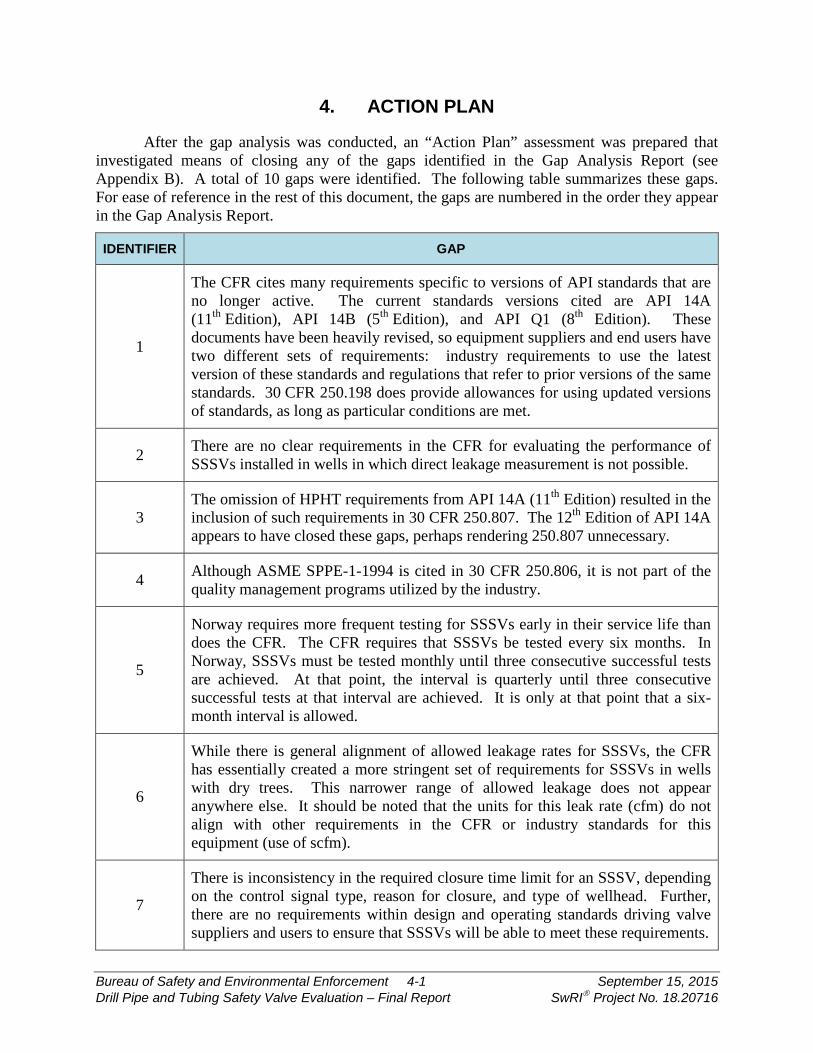
After the gap analysis was conducted, an “Action Plan” assessment was prepared that investigated means of closing any of the gaps identified in the Gap Analysis Report (see Appendix B). A total of 10 gaps were identified. The following table summarizes these gaps. For ease of reference in the rest of this document, the gaps are numbered in the order they appear in the Gap Analysis Report.
IDENTIFIER GAP
1
The CFR cites many requirements specific to versions of API standards that are no longer active. The current standards versions cited are API 14A (11th Edition), API 14B (5th Edition), and API Q1 (8th Edition). These documents have been heavily revised, so equipment suppliers and end users have two different sets of requirements: industry requirements to use the latest version of these standards and regulations that refer to prior versions of the same standards. 30 CFR 250.198 does provide allowances for using updated versions of standards, as long as particular conditions are met.
2 There are no clear requirements in the CFR for evaluating the performance of SSSVs installed in wells in which direct leakage measurement is not possible.
3 The omission of HPHT requirements from API 14A (11th Edition) resulted in the inclusion of such requirements in 30 CFR 250.807. The 12th Edition of API 14A appears to have closed these gaps, perhaps rendering 250.807 unnecessary.
4 Although ASME SPPE-1-1994 is cited in 30 CFR 250.806, it is not part of the quality management programs utilized by the industry.
5
Norway requires more frequent testing for SSSVs early in their service life than does the CFR. The CFR requires that SSSVs be tested every six months. In Norway, SSSVs must be tested monthly until three consecutive successful tests are achieved. At that point, the interval is quarterly until three consecutive successful tests at that interval are achieved. It is only at that point that a six-month interval is allowed.
6
While there is general alignment of allowed leakage rates for SSSVs, the CFR has essentially created a more stringent set of requirements for SSSVs in wells with dry trees. This narrower range of allowed leakage does not appear anywhere else. It should be noted that the units for this leak rate (cfm) do not align with other requirements in the CFR or industry standards for this equipment (use of scfm).
7
There is inconsistency in the required closure time limit for an SSSV, depending on the control signal type, reason for closure, and type of wellhead. Further, there are no requirements within design and operating standards driving valve suppliers and users to ensure that SSSVs will be able to meet these requirements.
Bureau of Safety and Environmental Enforcement 4-2 September 15, 2015 Drill Pipe and Tubing Safety Valve Evaluation – Final Report SwRI Project No. 18.20716
IDENTIFIER GAP
8
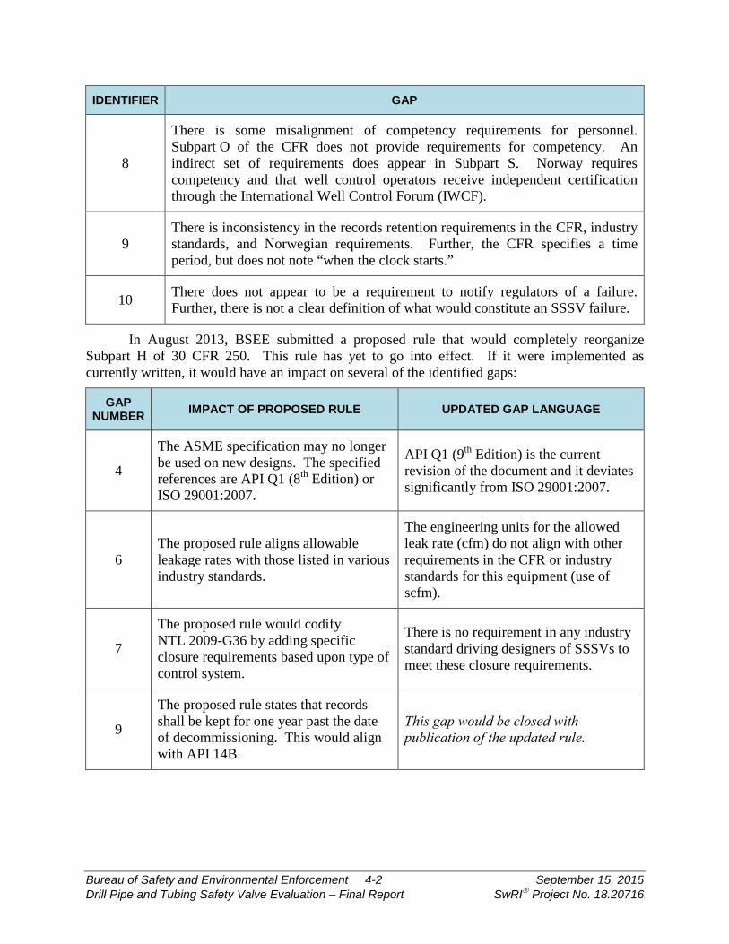
There is some misalignment of competency requirements for personnel. Subpart O of the CFR does not provide requirements for competency. An indirect set of requirements does appear in Subpart S. Norway requires competency and that well control operators receive independent certification through the International Well Control Forum (IWCF).
9 There is inconsistency in the records retention requirements in the CFR, industry standards, and Norwegian requirements. Further, the CFR specifies a time period, but does not note “when the clock starts.”
10 There does not appear to be a requirement to notify regulators of a failure. Further, there is not a clear definition of what would constitute an SSSV failure.
In August 2013, BSEE submitted a proposed rule that would completely reorganize Subpart H of 30 CFR 250. This rule has yet to go into effect. If it were implemented as currently written, it would have an impact on several of the identified gaps:
GAP NUMBER IMPACT OF PROPOSED RULE UPDATED GAP LANGUAGE
4
The ASME specification may no longer be used on new designs. The specified references are API Q1 (8th Edition) or ISO 29001:2007.
API Q1 (9th Edition) is the current revision of the document and it deviates significantly from ISO 29001:2007.
6 The proposed rule aligns allowable leakage rates with those listed in various industry standards.
The engineering units for the allowed leak rate (cfm) do not align with other requirements in the CFR or industry standards for this equipment (use of scfm).
7
The proposed rule would codify NTL 2009-G36 by adding specific closure requirements based upon type of control system.
There is no requirement in any industry standard driving designers of SSSVs to meet these closure requirements.
9
The proposed rule states that records shall be kept for one year past the date of decommissioning. This would align with API 14B.
This gap would be closed with publication of the updated rule.

Bureau of Safety and Environmental Enforcement 4-3 September 15, 2015 Drill Pipe and Tubing Safety Valve Evaluation – Final Report SwRI Project No. 18.20716
GAP NUMBER IMPACT OF PROPOSED RULE UPDATED GAP LANGUAGE
10
The proposed rule aligns with API 14A and API 14B. Additionally, a requirement for notification of BSEE has been included.
Specific section numbers of the reference documents for failure reporting are called out, so inclusion of an updated version of the document would obsolete these references.
The proposed rule would add a gap (noted as Gap #11) to the original list:
The proposed rule requires an independent third-party review of the design as part of life-cycle management. This requirement does not appear in any international regulations or industry standards.
The list of open gaps can now be listed as:
IDENTIFIER GAP
1
The CFR cites many requirements specific to versions of API standards that are no longer active. The current standards versions cited are API 14A (11th Edition), API 14B (5th Edition), and API Q1 (8th Edition). These documents have been heavily revised, so equipment suppliers and end users have two different sets of requirements: industry requirements to use the latest version of these standards and regulations that refer to prior versions of the same standards. 30 CFR 250.198 does provide allowances for using updated versions of standards, as long as particular conditions are met.
2 There are no clear requirements in the CFR for evaluating the performance of SSSVs installed in wells in which direct leakage measurement is not possible.
3 The omission of HPHT requirements from API 14A (11th Edition) resulted in the inclusion of such requirements in 30 CFR 250.807. The 12th Edition of API 14A appears to have closed these gaps, perhaps rendering 250.807 unnecessary.
4 API Q1 (9th Edition) is the current revision of the document and it deviates significantly from ISO 29001:2007.
5
Norway requires more frequent testing for SSSVs early in their service life than does the CFR. The CFR requires that SSSVs be tested every six months. In Norway, SSSVs must be tested monthly until three consecutive successful tests are achieved. At that point, the interval is quarterly until three consecutive successful tests at that interval are achieved. It is only at that point that a six-month interval is allowed.
6 The units for the allowed leak rate (cfm) do not align with other requirements in the CFR or industry standards for this equipment (use of scfm).

Bureau of Safety and Environmental Enforcement 4-4 September 15, 2015 Drill Pipe and Tubing Safety Valve Evaluation – Final Report SwRI Project No. 18.20716
IDENTIFIER GAP
7 There is no requirement in any industry standard driving designers of SSSVs to meet these closure requirements.
8
There is some misalignment of competency requirements for personnel. Subpart O of the CFR does not provide requirements for competency. An indirect set of requirements does appear in Subpart S. Norway requires competency and that well control operators receive independent certification through the IWCF.
10 Specific section numbers of the reference documents for failure reporting are called out, so inclusion of an updated version of the document would obsolete these references.
11 The proposed rule requires an independent third-party review of the design as part of life-cycle management. This requirement does not appear in any international regulations or industry standards.
There are three key documents listed in Subpart H that have recently been updated: API Q1, API 14A, and API 14B. The new revisions of these documents are now the 9th, 12th, and 6th editions, respectively. The latest versions of these documents are more stringent than the previous versions. Thus, inclusion of these documents into the CFR would not reduce the level of fidelity in the code. Changing the references to these updated versions would close five gaps:
GAP NUMBER IMPACT OF PROPOSED RULE
1
The latest revisions to API 14A and API 14B are more stringent than the previous versions and do not relax any requirements. Referencing the 6th Edition of API 14B and the 12th Edition of API 14A would close this gap.
2
API 14B provides some guidance on how to handle such scenarios. The 6th Edition has more guidance than the 5th Edition. Incorporation of the 6th Edition would close this gap. However, it should be recognized that indirect measurement is a complicated and imprecise approach to leak measurement, particularly when the CFR has prescriptive requirements for quantifying the rate. BSEE should consider a means of forming an industry joint-industry project or task group to address this issue.
3
By including a direct reference to API 14A, 12th Edition, this section could be removed from the proposed rule. However, it should be pointed out that 250.807c lists other related equipment (e.g., tubulars, packagers, chokes, etc.) for which this rule applies. Aside from a handful of guidelines for packers in H2S applications, 30 CFR 250 does not treat this list of “related equipment” as safety equipment in any other clause. Thus, placing HPHT requirements for this equipment seems out of place. BSEE should take action to determine if further requirements are necessary.
Bureau of Safety and Environmental Enforcement 4-5 September 15, 2015 Drill Pipe and Tubing Safety Valve Evaluation – Final Report SwRI Project No. 18.20716
GAP NUMBER IMPACT OF PROPOSED RULE
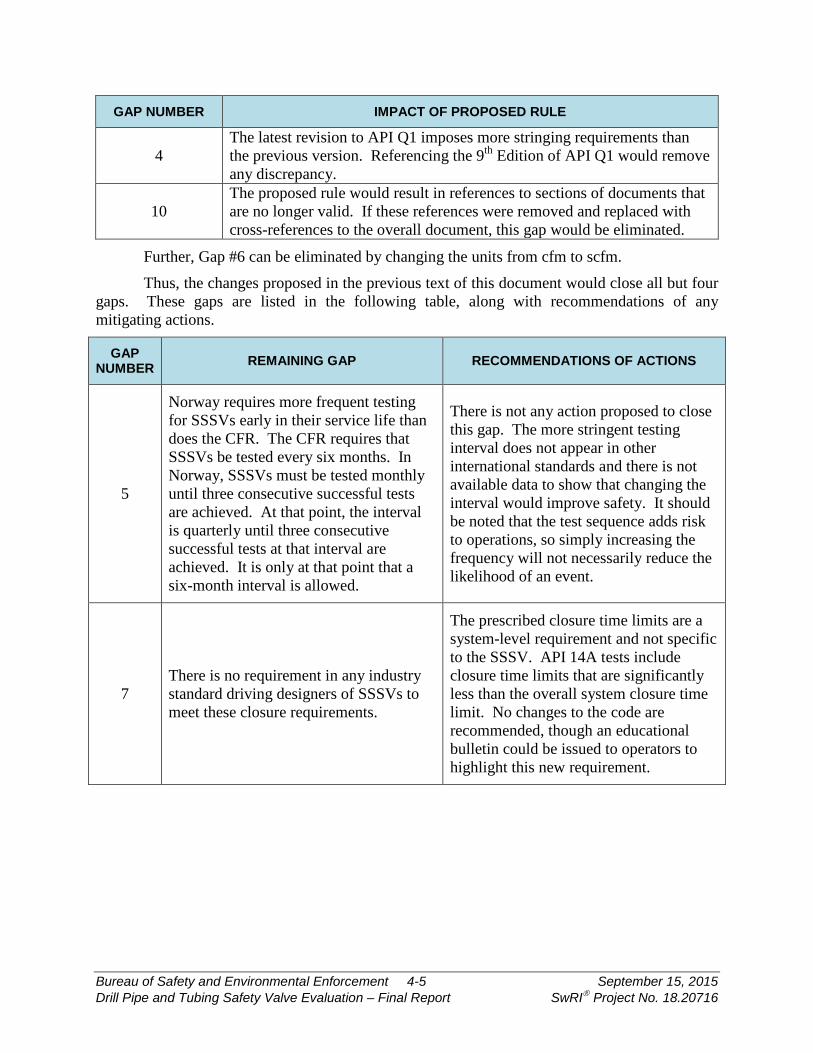
4 The latest revision to API Q1 imposes more stringing requirements than the previous version. Referencing the 9th Edition of API Q1 would remove any discrepancy.
10 The proposed rule would result in references to sections of documents that are no longer valid. If these references were removed and replaced with cross-references to the overall document, this gap would be eliminated.
Further, Gap #6 can be eliminated by changing the units from cfm to scfm.
Thus, the changes proposed in the previous text of this document would close all but four gaps. These gaps are listed in the following table, along with recommendations of any mitigating actions.
GAP NUMBER REMAINING GAP RECOMMENDATIONS OF ACTIONS
5
Norway requires more frequent testing for SSSVs early in their service life than does the CFR. The CFR requires that SSSVs be tested every six months. In Norway, SSSVs must be tested monthly until three consecutive successful tests are achieved. At that point, the interval is quarterly until three consecutive successful tests at that interval are achieved. It is only at that point that a six-month interval is allowed.
There is not any action proposed to close this gap. The more stringent testing interval does not appear in other international standards and there is not available data to show that changing the interval would improve safety. It should be noted that the test sequence adds risk to operations, so simply increasing the frequency will not necessarily reduce the likelihood of an event.
7 There is no requirement in any industry standard driving designers of SSSVs to meet these closure requirements.
The prescribed closure time limits are a system-level requirement and not specific to the SSSV. API 14A tests include closure time limits that are significantly less than the overall system closure time limit. No changes to the code are recommended, though an educational bulletin could be issued to operators to highlight this new requirement.

Bureau of Safety and Environmental Enforcement 4-6 September 15, 2015 Drill Pipe and Tubing Safety Valve Evaluation – Final Report SwRI Project No. 18.20716
GAP NUMBER REMAINING GAP RECOMMENDATIONS OF ACTIONS
8
There is some misalignment of competency requirements for personnel. Subpart O of the CFR does not provide requirements for competency. An indirect set of requirements does appear in Subpart S. Norway requires competency and that well control operators receive independent certification through the IWCF).
The competency requirement gap is somewhat narrowed by the new requirement for independent, third-party review of the design. If this change in the code were coupled with a more explicit reference in 30 CFR 250.805 to Subpart S, personnel qualification would be adequately addressed.
11
The proposed rule requires an independent third-party review of the design as part of life-cycle management. This requirement does not appear in any international regulations or industry standards.
This is a new requirement that would enhance safety, so no further changes are warranted.
The actions listed in this analysis are:
• Incorporate the proposed rule into the CFR with the following additional edits: o Change the gas leakage rate units from cubic feet per minute (cfm) to standard
cubic feet per minute (scfm).
o Update the reference edition of API 14A to the 12th Edition.
o Update the reference edition of API 14B to the 6th Edition.
o Update the reference edition of API Q1 to the 9th Edition.
o Modify all document references to cite the overall document and not cross-reference to specific sections.
• BSEE should consider a means of forming an industry joint-industry project or task group to address approaches for indirect measurement of leakage through SSSVs.
• Remove 30 CFR 250.807 as it pertains to SSSVs. BSEE should determine if the related equipment in 250.807c warrants requirements for all service conditions, not just for HPHT conditions.
• Modify 30 CFR 250.805 to add a reference to Subpart S.
• Issue an educational bulletin or other document to operators highlighting the closure time limit requirements for SSSV systems.

Bureau of Safety and Environmental Enforcement 5-1 September 15, 2015 Drill Pipe and Tubing Safety Valve Evaluation – Final Report SwRI Project No. 18.20716
5. CONCLUSIONS
This project assessed the alignment of the CFR to global regulations and industry standards. Some general conclusions can be made from this analysis:
• The CFR is the only prescriptive regulation among major worldwide jurisdictions. Most other regulations are performance-based or risk-based.
• There is a general lack of global requirements on non-permanently-installed equipment, such as kelly valves and drill-string safety valves.
• The CFR relies heavily on incorporation of national and international standards. However, the current approach in the CFR is to reference specific editions of each document and not necessarily the latest version. Thus, there is some misalignment between regulatory requirements and industry practices.
• The proposed reorganization of Subpart H addressed many current gaps in the CFR. Some slight edits to this proposed rule would close the vast majority of gaps. Two gaps that would still remain are (1) the difference in U.S. and Norwegian SSSV testing intervals and (2) the CFR requirement for third-party review of designs.
Bureau of Safety and Environmental Enforcement A-1 September 15, 2015 Drill Pipe and Tubing Safety Valve Evaluation – Final Report SwRI Project No. 18.20716
APPENDIX A
Literature Review Report
Drill Pipe and Tubing Safety Valve Evaluation
LITERATURE REVIEW REPORT
SwRI® Project No. 18.20716 BSEE Contract E14PC00024
Prepared for:
Bureau of Safety and Environmental Enforcement 381 Elden Street, HE 3314 Herndon, Virginia 20170
December 16, 2014
S O U T H W E S T R E S E A R C H I N S T I T U T E®
Drill Pipe and Tubing Safety Valve Evaluation
LITERATURE REVIEW REPORT
SwRI® Project No. 18.20716 BSEE Contract E14PC00024
Prepared for:
Bureau of Safety and Environmental Enforcement 381 Elden Street, HE 3314 Herndon, Virginia 20170
Prepared by:
Shane Siebenaler
Approved:
_____________________________________ Edgar B. Bowles, Jr., Director Fluids and Machinery Engineering Department

ADVERTISING, CONFIDENTIALITY, AND RECORD RETENTION POLICY
All work related to this project is subject to the Southwest Research Institute® Advertising, Confidentiality, and Record Retention Policy. This policy specifically addresses the distribution of abridged versions of SwRI® reports (including excerpts) and also restricts the use of the SwRI name, logo, and test results for advertising purposes. SwRI policies specifically prohibit the use in advertising of its name, logo, and results provided by our studies. The following paragraph, extracted verbatim from SwRI contractual documents clarifies this point:
“SwRI shall not publish or make known to others the subject matter or results of the Project or any information obtained in connection therewith which is proprietary and confidential to Client without Client’s written approval. No advertising or publicity containing any reference to SwRI, or any of their employees, either directly or by implication shall be made use of by Client or on Client’s behalf without SwRI’s written approval. In the event Client distributes any report issued by SwRI on this Project outside its own organization, such report shall be used in its entirety, unless SwRI approves a summary of abridgment for distribution.” SwRI will retain a record copy of the report for a period of five (5) years. This permits us
to answer questions that may be raised after a report has been mailed and provides a basis for additional work, if required. The contents of the report and any information that comes into our possession during the course of a study are held confidential to the company conducting the study and are not disclosed to anyone without client’s prior permission.
TABLE OF CONTENTS Section Page
TABLE OF CONTENTS ............................................................................................................ iii
LIST OF TABLES ...................................................................................................................... iv
EXECUTIVE SUMMARY ........................................................................................................... v
1. INTRODUCTION ....................................................................................................... 1-1
1.1 Background ......................................................................................................... 1-1
1.2 Equipment Evaluated .......................................................................................... 1-1
1.3 Data Gathering process ....................................................................................... 1-2
1.4 Report Context .................................................................................................... 1-2
1.5 Report Organization ............................................................................................ 1-2
2. REGULATORY PICTURE .......................................................................................... 2-1
2.1 United States Offshore Regulations ..................................................................... 2-1
2.2 International Regulations ..................................................................................... 2-1
2.2.1 Australia ....................................................................................................... 2-1 2.2.2 Brazil ............................................................................................................ 2-2 2.2.3 Canada ......................................................................................................... 2-2 2.2.4 Denmark ....................................................................................................... 2-2 2.2.5 Netherlands .................................................................................................. 2-2 2.2.6 New Zealand ................................................................................................ 2-3 2.2.7 Norway ......................................................................................................... 2-3 2.2.8 United Kingdom ............................................................................................ 2-3
2.3 United States Onshore Regulations ..................................................................... 2-3
2.3.1 Federal ......................................................................................................... 2-3 2.3.2 State ............................................................................................................. 2-4
2.4 Overall Regulatory Structure ............................................................................... 2-5
3. EQUIPMENT REQUIREMENTS ................................................................................ 3-1
3.1 General Organization .......................................................................................... 3-1
3.2 Subsurface Safety Valves (SSSVs) ..................................................................... 3-1
3.2.1 Overall Equipment Summary ........................................................................ 3-1 3.2.2 Federal Requirements .................................................................................. 3-4 3.2.3 State Requirements ...................................................................................... 3-9 3.2.4 International Requirements ......................................................................... 3-16 3.2.5 Standards Overview ................................................................................... 3-18
3.3 Kelly Valves ....................................................................................................... 3-23
3.3.1 Overall Equipment Summary ...................................................................... 3-23 3.3.2 Federal Requirements ................................................................................ 3-24
Bureau of Safety and Environmental Enforcement iii December 16, 2014 Drill Pipe and Tubing Safety Valve Evaluation – Literature Review Report SwRI Project No. 18.20716
TABLE OF CONTENTS (cont'd) Section Page
3.3.3 State Requirements .................................................................................... 3-27 3.3.4 International Requirements ......................................................................... 3-29 3.3.5 Standards Overview ................................................................................... 3-30
3.4 Drill String Safety Valve ..................................................................................... 3-31
3.4.1 Overall Equipment Summary ...................................................................... 3-31 3.4.2 Federal Requirements ................................................................................ 3-32 3.4.3 State Requirements .................................................................................... 3-34 3.4.4 International Requirements ......................................................................... 3-36 3.4.5 Standards Overview ................................................................................... 3-36
3.5 Tubing Plugs ..................................................................................................... 3-36
3.5.1 Overall Equipment Summary ...................................................................... 3-36 3.5.2 Federal Requirements ................................................................................ 3-37 3.5.3 State Requirements .................................................................................... 3-40 3.5.4 International Requirements ......................................................................... 3-42 3.5.5 Standards Overview ................................................................................... 3-42
4. SUMMARY ................................................................................................................ 4-1
5. REFERENCES .......................................................................................................... 5-1
LIST OF TABLES Section Page
Table 2.1 Overview of International Regulatory Positions ...................................................... 2-2 Table 2.2 Overview of U.S. State Regulatory Positions on SSSVs and Similar Products ....... 2-4
Bureau of Safety and Environmental Enforcement iv December 16, 2014 Drill Pipe and Tubing Safety Valve Evaluation – Literature Review Report SwRI Project No. 18.20716

EXECUTIVE SUMMARY A literature review was performed to capture global requirements for key pieces of safety
equipment and to also incorporate a review of key industry standards. There were four general categories of equipment studies that were included in this report:
• Subsurface safety valves as defined in API 14A/ISO 10432. These products include both surface-controlled and subsurface-controlled valves of both tubing-retrievable and wireline-retrievable varieties. It should be noted that many international jurisdictions refer to such products as downhole safety valves (DHSVs). For purposes of this report, SSSV will be used to note requirements of these products, except where verbatim text is taken from a regulation or standard. In the case where verbatim text is used, the nomenclature will not be edited from the source material.
• Upper and lower kelly valves used in drilling operating. • Drill-string safety valves (called drill-tube safety valves in some places). • Tubing plugs.
The high-level conclusions from this literature review are:
• The U.S. is the sole national jurisdiction that has prescriptive requirements for safety-related equipment. Other global bodies lean on risk-based or performance-based systems in which guidelines are provided, but not prescriptive requirements. It should be noted that it is unclear how often operators deviate from accepted standards when making applications for safety cases. It is possible that an unwritten expectation of compliance exists and that the guidelines essentially result in more direct requirements. In that case, the most thorough set of international regulations would be with the Norwegian PSA, particularly in regards to SSSVs.
• SSSVs are given far more attention with respect to verification, validation, and field testing requirements in regulations compared to the other products studied in this project. A key reason for this observation is that most tubing-retrievable SSSVs are essentially permanently-installed equipment, where the other three products are not.
• API 14A is leaned on as the recognized standard for SSSVs. The current revision of this standard (11th edition) does not contain prescriptive requirements for verification. The CFR has incorporated additional verification requirements for SSSVs used in HPHT applications. The upcoming release of the 12th edition of API 14A will roll these requirements into the specification, perhaps obsoleting the need for that section of the CFR.
• Most regulations point to API 14B for establishing leak rate criteria for SSSVs. These rates are 400 cm3/min for liquid and 15 scfm for gas. The leakage rates for U.S. waters are more stringent, as the allowed rates are 200 cm3/min and 5 scfm per 30 CFR 250.804.
Bureau of Safety and Environmental Enforcement v December 16, 2014 Drill Pipe and Tubing Safety Valve Evaluation – Literature Review Report SwRI Project No. 18.20716
1. INTRODUCTION
1.1 Background The regulatory framework in place for The U.S. Outer Continental shelf (OCS) activities
relating to tubing-retrievable subsurface safety valves (SSSVs) and similar safety products has been largely reactive to industry standardization of such equipment. Requirements for validation and verification often are implicit in the referenced specifications and not augmented by separate requirements in the regulations. However, as technology has evolved, and as offshore wells are being drilled in high-pressure and high-temperature (HPHT) wells, there is some disconnect between industry standards and regulatory response. A fairly recent example relates to requirements for SSSVs used in OCS applications. The Code of Federal Regulations (CFR) referenced that valves need to meet the requirements of API 14A, specifically the 10th edition. When the 11th edition of the document was released, the traditional 150% design pressure was replaced with a 5,000-psi above-bore pressure allowance. As has been pointed out numerous times by the Bureau of Safety and Environmental Enforcement (BSEE) [and formerly Minerals Management Service (MMS)] officials, the verification requirements of the 11th edition are all of two sentences. It took several years for the CFR to absorb the 11th edition, and only with additional requirements for HPHT applications. Such divergence in standardized requirements shifts additional responsibility for review to BSEE and reduces the industry’s success in standardization. It is critical to identify gaps between current industry practices and regulations to improve safety in the OCS.
An example of the lag between regulations, industry standards, and current practices can be found in testing requirements for tubing-retrievable safety valves (TRSVs) installed in the OCS. The CFR and API 14B both reference leakage requirements that are direct measurements through the closure mechanism. However, subsea trees prevent direct measurement, resulting in many operators utilizing an indirect approach through pressure monitoring. Thus, both the CFR and industry standards have not “caught up to” current practices.
To initiate the effort in identifying and then closing gaps in regulations, a literature review was performed to capture global requirements for key pieces of safety equipment and to also incorporate a review of key industry standards. This report presents the findings from this literature review.
1.2 Equipment Evaluated There were four general categories of equipment studies that were included in this report:
• Subsurface safety valves as defined in API 14A/ISO 10432. These products include both surface-controlled and subsurface-controlled valves of both tubing-retrievable and wireline-retrievable varieties. It should be noted that many international jurisdictions refer to such products as downhole safety valves (DHSVs). For purposes of this report, SSSV will be used to note requirements of these products, except where verbatim text is taken from a regulation or standard. In the case where verbatim text is used, the nomenclature will not be edited from the source material.
• Upper and lower kelly valves used in drilling operating. • Drill-string safety valves (called drill-tube safety valves in some places). • Tubing plugs.
Bureau of Safety and Environmental Enforcement 1-1 December 16, 2014 Drill Pipe and Tubing Safety Valve Evaluation – Literature Review Report SwRI Project No. 18.20716
1.3 Data Gathering Process The following sources of information were consulted in order to generate the content of
this report:
• The Code of Federal Regulations (CFR) was reviewed by use of the eCFR tool available on the website of the U.S. Government Printing Office.
• Notices to Lessees (NTLs) and Safety Notices were reviewed through the BSEE website. • Regulators from the International Regulators Forum (IRF) were contacted directly
utilizing contact information available on the IRF website. In most instances, the responding regulators provided links to online regulations or guidelines, but did not provide any commentary on the information.
• A web search was performed to identify various state agencies that oversee oil and gas operations in their respective states. These agencies were then contacted to determine regulations in place governing such equipment.
• Various national and international standards were consulted to capture key equipment requirements.
A list of sources used to compile the information in this report can be found in Section 5.
1.4 Report Context This report is a literature review of the information provided by regulators and found
through various means described in Section 1.3. The findings will be contrasted (e.g., domestic vs. international, offshore vs. onshore, etc.) in a follow-up project task as part of a gap analysis. This report is simply an overview of the collected information.
It should be noted that some of this content is “in flux” and may be updated in subsequent project reporting. As an example, two key standards governing the use of SSSVs are API 14A and API 14B. At the writing of this report, both standards are being heavily revised. This report will reflect the current state of these revisions, but any further changes will need to be captured in future project documents. Also, some regulators have not yet been responsive to requests for information; any additional information received will be included in future reporting.
1.5 Report Organization The technical content for this report is divided into two main sections:
• Regulatory Picture (Section 2) – This section summarizes the regulatory approach from jurisdictions around the world. In particular, this section will outline the two prevalent models adopted by various entities: prescriptive regulation and risk-based case applications.
• Equipment Requirements (Section 3) – This section summarizes global requirements applicable to the four categories of equipment that were studied. A discussion of relevant international standards is also provided.
The intent of this report is to capture the general regulatory framework around the globe. Most of the content provided in the report will be the actual text with additional context, where applicable. Where text is extracted verbatim from a source, it will be italicized and placed inside of a box.
Bureau of Safety and Environmental Enforcement 1-2 December 16, 2014 Drill Pipe and Tubing Safety Valve Evaluation – Literature Review Report SwRI Project No. 18.20716

2. REGULATORY PICTURE
2.1 United States Offshore Regulations The regulatory framework for the U.S. Outer Continental Shelf (OCS) is captured in
30 CFR 250. The cadence of the code is to frame the regulations in the form of answers to posed hypothetical questions. The CFR provides a fairly prescriptive framework whereby specific requirements for equipment are imposed. As will be evident in subsequent sections of this document, this prescriptive approach does not align with the safety-case approach adopted by most other international regulators.
The CFR utilizes a combination of prescriptive requirements, as well as call-outs to recognized international and national standards. As an example, 30 CFR 250.801 provides a detailed list of prescriptive requirements for subsurface safety valves. Several sections later (30 CFR 250.806), there is a requirement that SSSVs meet the requirements of API 14A. In general, such equipment specifications are restricted to the design and manufacture of equipment, as opposed to the operation of equipment in the field.
2.2 International Regulations All regulatory bodies in the International Regulators Forum were contacted in regards to
their regulatory approaches. Most international regulators use a performance-based approach to equipment requirements. This risk-based approach is often called an As Low as Reasonably Possible (ALARP) model of risk. A report from the International Association of Oil and Gas Producers (OGP) group characterized such models in this manner:
“The role of the regulator in performance-based regimes is to provide independent assurance that health and safety risks are properly controlled by challenging the operator’s risk management arrangements during safety case assessment and then verifying by planned inspection that the operator has implemented its risk management commitments documented in the safety case.”
An element of the safety case model is the voluntary adherence to international standards. As an example, European regulators do not directly require the use of a standard, unless the standard is invoked by a contract. The safety cases are a confidential set of documents between the operator and the regulator. Regulators contacted for this project were not in a position to disseminate the contents of these documents.
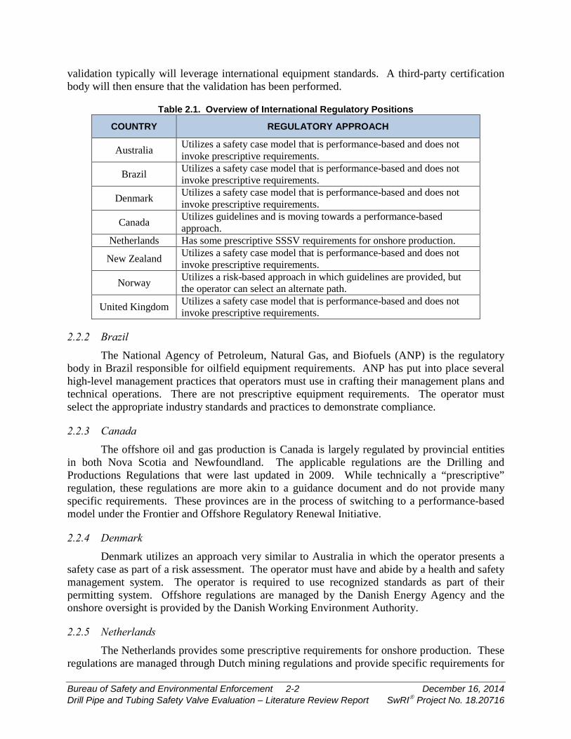
Table 2.1 provides a general overview of the approach to requirements in various jurisdictions for offshore production. More details can be found in the subsequent sections of this report. Section 3 contains equipment-specific requirements.
2.2.1 Australia Australia uses a performance-based approach with very few prescriptive requirements. In
particular, there is an absence of direct regulations for any of the pieces of equipment being studied in this project. The regulatory framework requires operators to generate a safety case in which the operator may invoke industry standards. The safety case must be reviewed by the National Offshore Petroleum Safety and Environmental Management Authority (NOPSEMA) prior to any work being initiated. An element of the approval process is the agreement between the operator and NOPSEMA on what validation of equipment must be performed. Such
Bureau of Safety and Environmental Enforcement 2-1 December 16, 2014 Drill Pipe and Tubing Safety Valve Evaluation – Literature Review Report SwRI Project No. 18.20716
validation typically will leverage international equipment standards. A third-party certification body will then ensure that the validation has been performed.
Table 2.1. Overview of International Regulatory Positions
COUNTRY REGULATORY APPROACH
Australia Utilizes a safety case model that is performance-based and does not invoke prescriptive requirements.
Brazil Utilizes a safety case model that is performance-based and does not invoke prescriptive requirements.
Denmark Utilizes a safety case model that is performance-based and does not invoke prescriptive requirements.
Canada Utilizes guidelines and is moving towards a performance-based approach.
Netherlands Has some prescriptive SSSV requirements for onshore production.
New Zealand Utilizes a safety case model that is performance-based and does not invoke prescriptive requirements.
Norway Utilizes a risk-based approach in which guidelines are provided, but the operator can select an alternate path.
United Kingdom Utilizes a safety case model that is performance-based and does not invoke prescriptive requirements.
2.2.2 Brazil The National Agency of Petroleum, Natural Gas, and Biofuels (ANP) is the regulatory
body in Brazil responsible for oilfield equipment requirements. ANP has put into place several high-level management practices that operators must use in crafting their management plans and technical operations. There are not prescriptive equipment requirements. The operator must select the appropriate industry standards and practices to demonstrate compliance.
2.2.3 Canada The offshore oil and gas production is Canada is largely regulated by provincial entities
in both Nova Scotia and Newfoundland. The applicable regulations are the Drilling and Productions Regulations that were last updated in 2009. While technically a “prescriptive” regulation, these regulations are more akin to a guidance document and do not provide many specific requirements. These provinces are in the process of switching to a performance-based model under the Frontier and Offshore Regulatory Renewal Initiative.
2.2.4 Denmark Denmark utilizes an approach very similar to Australia in which the operator presents a
safety case as part of a risk assessment. The operator must have and abide by a health and safety management system. The operator is required to use recognized standards as part of their permitting system. Offshore regulations are managed by the Danish Energy Agency and the onshore oversight is provided by the Danish Working Environment Authority.
2.2.5 Netherlands The Netherlands provides some prescriptive requirements for onshore production. These
regulations are managed through Dutch mining regulations and provide specific requirements for
Bureau of Safety and Environmental Enforcement 2-2 December 16, 2014 Drill Pipe and Tubing Safety Valve Evaluation – Literature Review Report SwRI Project No. 18.20716
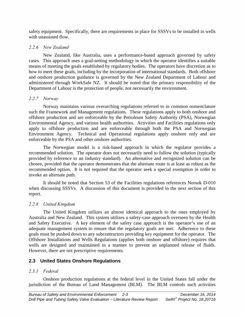
safety equipment. Specifically, there are requirements in place for SSSVs to be installed in wells with unassisted flow.
2.2.6 New Zealand New Zealand, like Australia, uses a performance-based approach governed by safety
cases. This approach uses a goal-setting methodology in which the operator identifies a suitable means of meeting the goals established by regulatory bodies. The operators have discretion as to how to meet these goals, including by the incorporation of international standards. Both offshore and onshore production guidance is governed by the New Zealand Department of Labour and administered through WorkSafe NZ. It should be noted that the primary responsibility of the Department of Labour is the protection of people, not necessarily the environment.
2.2.7 Norway Norway maintains various overarching regulations referred to in common nomenclature
such the Framework and Management regulations. These regulations apply to both onshore and offshore production and are enforceable by the Petroleum Safety Authority (PSA), Norwegian Environmental Agency, and various health authorities. Activities and Facilities regulations only apply to offshore production and are enforceable through both the PSA and Norwegian Environment Agency. Technical and Operational regulations apply onshore only and are enforceable by the PSA and other onshore authorities.
The Norwegian model is a risk-based approach in which the regulator provides a recommended solution. The operator does not necessarily need to follow the solution (typically provided by reference to an industry standard). An alternative and recognized solution can be chosen, provided that the operator demonstrates that the alternate route is at least as robust as the recommended option. It is not required that the operator seek a special exemption in order to invoke an alternate path.
It should be noted that Section 53 of the Facilities regulations references Norsok D-010 when discussing SSSVs. A discussion of this document is provided in the next section of this report.
2.2.8 United Kingdom The United Kingdom utilizes an almost identical approach to the ones employed by
Australia and New Zealand. This system utilizes a safety-case approach overseen by the Health and Safety Executive. A key element of the safety case approach is the operator’s use of an adequate management system to ensure that the regulatory goals are met. Adherence to these goals must be pushed down to any subcontractors providing key equipment for the operator. The Offshore Installations and Wells Regulations (applies both onshore and offshore) requires that wells are designed and maintained in a manner to prevent an unplanned release of fluids. However, there are not prescriptive requirements.
2.3 United States Onshore Regulations
2.3.1 Federal Onshore production regulations at the federal level in the United States fall under the
jurisdiction of the Bureau of Land Management (BLM). The BLM controls such activities
Bureau of Safety and Environmental Enforcement 2-3 December 16, 2014 Drill Pipe and Tubing Safety Valve Evaluation – Literature Review Report SwRI Project No. 18.20716
through 43 CRF 3160. This title of the CFR does not contain any requirements for the equipment under review in this project. Federally-regulated land on Native American reservations is governed through the Department of Indian Affairs. This department also does not control any of this equipment through its regulations in 25 CFR.
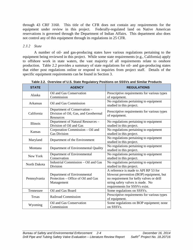
2.3.2 State A number of oil- and gas-producing states have various regulations pertaining to the
equipment being reviewed in this project. While some state requirements (e.g., California) apply to offshore work in state waters, the vast majority of all requirements relate to onshore production. Table 2.2 provides a summary of state regulations for oil- and gas-producing states that either post regulations online or respond to inquiries from project staff. Details of the specific equipment requirements can be found in Section 3.
Table 2.2. Overview of U.S. State Regulatory Positions on SSSVs and Similar Products
STATE AGENCY REGULATIONS
Alaska Oil and Gas Conservation Commission
Prescriptive requirements for various types of equipment.
Arkansas Oil and Gas Commission No regulations pertaining to equipment studied in this project.
California Department of Conservation – Division of Oil, Gas, and Geothermal Resources
Prescriptive requirements for various types of equipment.
Illinois Department of Natural Resources – Division of Oil and Gas
No regulations pertaining to equipment studied in this project.
Kansas Corporation Commission – Oil and Gas Division
No regulations pertaining to equipment studied in this project.
Maryland Department of the Environment No regulations pertaining to equipment studied in this project.
Montana Department of Environmental Quality No regulations pertaining to equipment studied in this project.
New York Department of Environmental Conservation
No regulations pertaining to equipment studied in this project.
North Dakota Industrial Commission – Oil and Gas Division
No regulations pertaining to equipment studied in this project.
Pennsylvania Department of Environmental Protection – Office of Oil and Gas Management
A reference is made to API RP 53 for blowout prevention (BOP) equipment, but no requirement for kelly valves or drill string safety valves is made. No requirements for SSSVs exist.
Tennessee Oil and Gas Board Some regulations on SSSVs.
Texas Railroad Commission Prescriptive requirements for various types of equipment.
Wyoming Oil and Gas Conservation Commission
Some regulations on BOP equipment; none on SSSVs.
Bureau of Safety and Environmental Enforcement 2-4 December 16, 2014 Drill Pipe and Tubing Safety Valve Evaluation – Literature Review Report SwRI Project No. 18.20716
2.4 Overall Regulatory Structure The literature review revealed that most regulatory bodies outside of the United States do
not lean on prescriptive requirements for equipment. Instead, they utilize a risk-based approach that allows for the operator to present an application-specific case. An important element of both the risk-based and prescriptive approaches is the reliance on national and international standards. In other words, the technical requirements of the equipment are most often placed under the microscope of industry experts on such technology. An overview of some of the key standards for the equipment in this study can be found in the next section of this report.
Bureau of Safety and Environmental Enforcement 2-5 December 16, 2014 Drill Pipe and Tubing Safety Valve Evaluation – Literature Review Report SwRI Project No. 18.20716
3. EQUIPMENT REQUIREMENTS
3.1 General Organization This section is organized by the four classes of equipment being analyzed:
• Subsurface safety valves • Kelly valves • Drill string safety valves • Tubing plugs
For each of these types of equipment, the following areas of discussion are included:
• Federal code requirements • Domestic requirements • International requirements • Industry standards
International standards can include a significant amount of information about the design, manufacturer, validation, use, maintenance, and repair of equipment. In the review of these standards for this project, consideration was given to requirements in the following areas:
• Conditions that warrant required installation of equipment.
• Verification1 requirements, particularly those applicable to high-pressure and/or high-temperature environments.
• Validation2 requirements. • Field testing requirements.
It should be noted that industry standards can be comprehensive documents pertaining to many design, manufacture, transport, and operational aspects of the equipment. The overview presented in this report extracts elements of key standards that are directly relevant to the regulatory goal for which they are going to meet. An example of a type of requirement from a standard that is included in this report would be allowable leakage rates during testing. An example of a requirement from a standard that is not discussed in this report is recordkeeping requirements for subcontractors of brazing processes used in the manufacture of a component.
3.2 Subsurface Safety Valves (SSSVs)
3.2.1 Overall Equipment Summary This section discusses the high-level requirements noted in Section 3.1 across all
regulations and standards studied for this product. The subsequent sections provide the detailed content for federal, state, and international regulations, as well as equipment standards.
1 This report assumes the definition of verification utilized in API Specification Q1, 9th Edition: “Process of examining the result of design and development output to determine conformity with specified requirements.” 2 This report assumes the definition of validation utilized in API Specification Q1, 9th Edition: “Process of proving a design by testing to demonstrate conformity of the product to design requirements.”
Bureau of Safety and Environmental Enforcement 3-1 December 16, 2014 Drill Pipe and Tubing Safety Valve Evaluation – Literature Review Report SwRI Project No. 18.20716
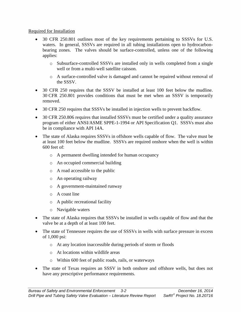
Required for Installation
• 30 CFR 250.801 outlines most of the key requirements pertaining to SSSVs for U.S. waters. In general, SSSVs are required in all tubing installations open to hydrocarbon-bearing zones. The valves should be surface-controlled, unless one of the following applies:
o Subsurface-controlled SSSVs are installed only in wells completed from a single well or from a multi-well satellite caisson.
o A surface-controlled valve is damaged and cannot be repaired without removal of the SSSV.
• 30 CFR 250 requires that the SSSV be installed at least 100 feet below the mudline. 30 CFR 250.801 provides conditions that must be met when an SSSV is temporarily removed.
• 30 CFR 250 requires that SSSVs be installed in injection wells to prevent backflow.
• 30 CFR 250.806 requires that installed SSSVs must be certified under a quality assurance program of either ANSI/ASME SPPE-1-1994 or API Specification Q1. SSSVs must also be in compliance with API 14A.
• The state of Alaska requires SSSVs in offshore wells capable of flow. The valve must be at least 100 feet below the mudline. SSSVs are required onshore when the well is within 600 feet of:
o A permanent dwelling intended for human occupancy
o An occupied commercial building
o A road accessible to the public
o An operating railway
o A government-maintained runway
o A coast line
o A public recreational facility
o Navigable waters
• The state of Alaska requires that SSSVs be installed in wells capable of flow and that the valve be at a depth of at least 100 feet.
• The state of Tennessee requires the use of SSSVs in wells with surface pressure in excess of 1,000 psi:
o At any location inaccessible during periods of storm or floods
o At locations within wildlife areas
o Within 600 feet of public roads, rails, or waterways
• The state of Texas requires an SSSV in both onshore and offshore wells, but does not have any prescriptive performance requirements.
Bureau of Safety and Environmental Enforcement 3-2 December 16, 2014 Drill Pipe and Tubing Safety Valve Evaluation – Literature Review Report SwRI Project No. 18.20716
• International requirements for installation can be found in Section 3.2.4 of this report. There are no prescriptive requirements for how the valve should be installed, though API 14A and API 14B appear as widely-recognized standards that could be used in a safety case justification.
• Canada requires an SSSV be installed in wells capable of flow, but only references API 14A and API 14B without additional requirements.
Verification Requirements
• 30 CFR 250.807 provides verification requirements that must be met for valves in HPHT environments. This section of the CFR does not provide a prescriptive list of verification requirements. Instead, it requires that an operator produce written justification that the valve is fit for the intended service.
• The current revision of API 14A (11th edition) does not provide any prescriptive verification requirements. The upcoming release of the 12th edition will add new requirements, including an annex on verification for HPHT applications.
Validation Requirements
• API 14A (11th edition) requires that each model of an SSSV undergo a validation test by an independent test agency. The 12th edition of the document adds new validation grades that, in turn, introduce additional validation testing requirements.
Field-Testing Requirements
• 30 CFR 250 points to API RP 14B for requirements for inspections, maintenance, and testing.
• 30 CFR 250.803 requires that the SSSV be closed within two minutes after closure of the surface safety valve when commanded by an emergency shutdown device.
• 30 CFR 250.804 requires that testing be performed on the SSSV every six months. Liquid leakage rates cannot exceed 200 cc/min and gas leaks cannot exceed 5 scfm. Testing shall be in accordance with API 14B.
• 30 CFR 250.803 requires that subsurface-controlled SSSVs be removed, inspected, and repaired or adjusted (as necessary) and reinstalled every six months for valves not in a landing nipple and 12 months for valves in a landing nipple.
• The state of Alaska requires testing of SSSVs every six months. This test does not allow any leakage.
• The state of California requires SSSVs to be tested every six months. There appears to be some inconsistency in the California code. Section 1724 references testing at six-month intervals, while Section 1747 uses a period of one month. It is assumed the latter is really intended as a first test within the first month of installation and not at regular intervals.
• There are no prescriptive requirements internationally for testing, though API 14A and API 14B appear to be widely-recognized standards that could be used in a safety case justification.
Bureau of Safety and Environmental Enforcement 3-3 December 16, 2014 Drill Pipe and Tubing Safety Valve Evaluation – Literature Review Report SwRI Project No. 18.20716
• API 14B requires field testing every six months. The allowed leakage rates are 400 cm3/min for liquid wells and 15 scfm for gas.
• Norsok D-0101 recommends more frequent testing of SSSVs, particularly until a documented history of performance is achieved. The allowed liquid leakage rate is higher for liquid in comparison to API 14A, but the gas rates are the same.
• Canada does not specify testing requirements beyond adhering to API 14B.
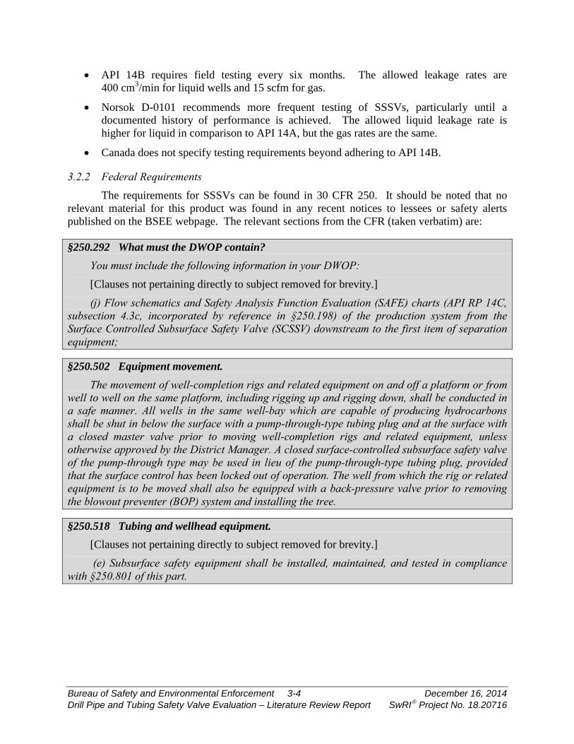
3.2.2 Federal Requirements The requirements for SSSVs can be found in 30 CFR 250. It should be noted that no
relevant material for this product was found in any recent notices to lessees or safety alerts published on the BSEE webpage. The relevant sections from the CFR (taken verbatim) are:
§250.292 What must the DWOP contain? You must include the following information in your DWOP: [Clauses not pertaining directly to subject removed for brevity.]
(j) Flow schematics and Safety Analysis Function Evaluation (SAFE) charts (API RP 14C, subsection 4.3c, incorporated by reference in §250.198) of the production system from the Surface Controlled Subsurface Safety Valve (SCSSV) downstream to the first item of separation equipment;
§250.502 Equipment movement. The movement of well-completion rigs and related equipment on and off a platform or from
well to well on the same platform, including rigging up and rigging down, shall be conducted in a safe manner. All wells in the same well-bay which are capable of producing hydrocarbons shall be shut in below the surface with a pump-through-type tubing plug and at the surface with a closed master valve prior to moving well-completion rigs and related equipment, unless otherwise approved by the District Manager. A closed surface-controlled subsurface safety valve of the pump-through type may be used in lieu of the pump-through-type tubing plug, provided that the surface control has been locked out of operation. The well from which the rig or related equipment is to be moved shall also be equipped with a back-pressure valve prior to removing the blowout preventer (BOP) system and installing the tree.
§250.518 Tubing and wellhead equipment. [Clauses not pertaining directly to subject removed for brevity.]
(e) Subsurface safety equipment shall be installed, maintained, and tested in compliance with §250.801 of this part.
Bureau of Safety and Environmental Enforcement 3-4 December 16, 2014 Drill Pipe and Tubing Safety Valve Evaluation – Literature Review Report SwRI Project No. 18.20716
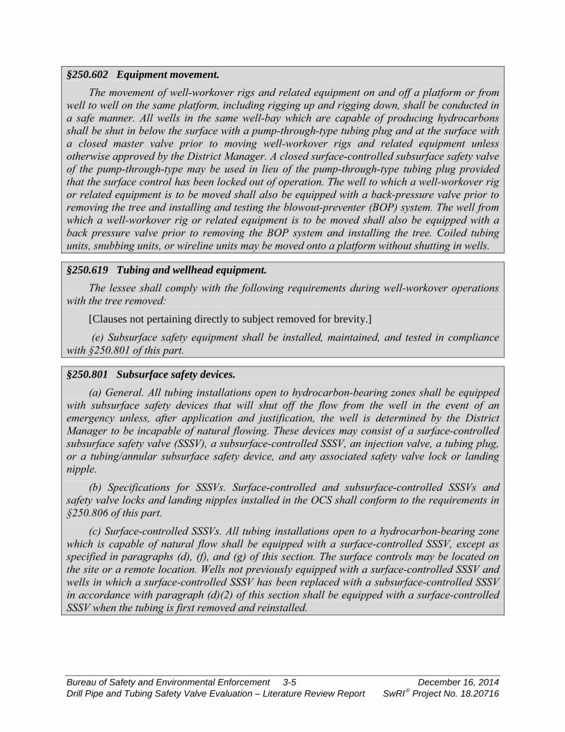
§250.602 Equipment movement. The movement of well-workover rigs and related equipment on and off a platform or from
well to well on the same platform, including rigging up and rigging down, shall be conducted in a safe manner. All wells in the same well-bay which are capable of producing hydrocarbons shall be shut in below the surface with a pump-through-type tubing plug and at the surface with a closed master valve prior to moving well-workover rigs and related equipment unless otherwise approved by the District Manager. A closed surface-controlled subsurface safety valve of the pump-through-type may be used in lieu of the pump-through-type tubing plug provided that the surface control has been locked out of operation. The well to which a well-workover rig or related equipment is to be moved shall also be equipped with a back-pressure valve prior to removing the tree and installing and testing the blowout-preventer (BOP) system. The well from which a well-workover rig or related equipment is to be moved shall also be equipped with a back pressure valve prior to removing the BOP system and installing the tree. Coiled tubing units, snubbing units, or wireline units may be moved onto a platform without shutting in wells.
§250.619 Tubing and wellhead equipment. The lessee shall comply with the following requirements during well-workover operations
with the tree removed: [Clauses not pertaining directly to subject removed for brevity.]
(e) Subsurface safety equipment shall be installed, maintained, and tested in compliance with §250.801 of this part.
§250.801 Subsurface safety devices. (a) General. All tubing installations open to hydrocarbon-bearing zones shall be equipped
with subsurface safety devices that will shut off the flow from the well in the event of an emergency unless, after application and justification, the well is determined by the District Manager to be incapable of natural flowing. These devices may consist of a surface-controlled subsurface safety valve (SSSV), a subsurface-controlled SSSV, an injection valve, a tubing plug, or a tubing/annular subsurface safety device, and any associated safety valve lock or landing nipple.
(b) Specifications for SSSVs. Surface-controlled and subsurface-controlled SSSVs and safety valve locks and landing nipples installed in the OCS shall conform to the requirements in §250.806 of this part.
(c) Surface-controlled SSSVs. All tubing installations open to a hydrocarbon-bearing zone which is capable of natural flow shall be equipped with a surface-controlled SSSV, except as specified in paragraphs (d), (f), and (g) of this section. The surface controls may be located on the site or a remote location. Wells not previously equipped with a surface-controlled SSSV and wells in which a surface-controlled SSSV has been replaced with a subsurface-controlled SSSV in accordance with paragraph (d)(2) of this section shall be equipped with a surface-controlled SSSV when the tubing is first removed and reinstalled.
Bureau of Safety and Environmental Enforcement 3-5 December 16, 2014 Drill Pipe and Tubing Safety Valve Evaluation – Literature Review Report SwRI Project No. 18.20716
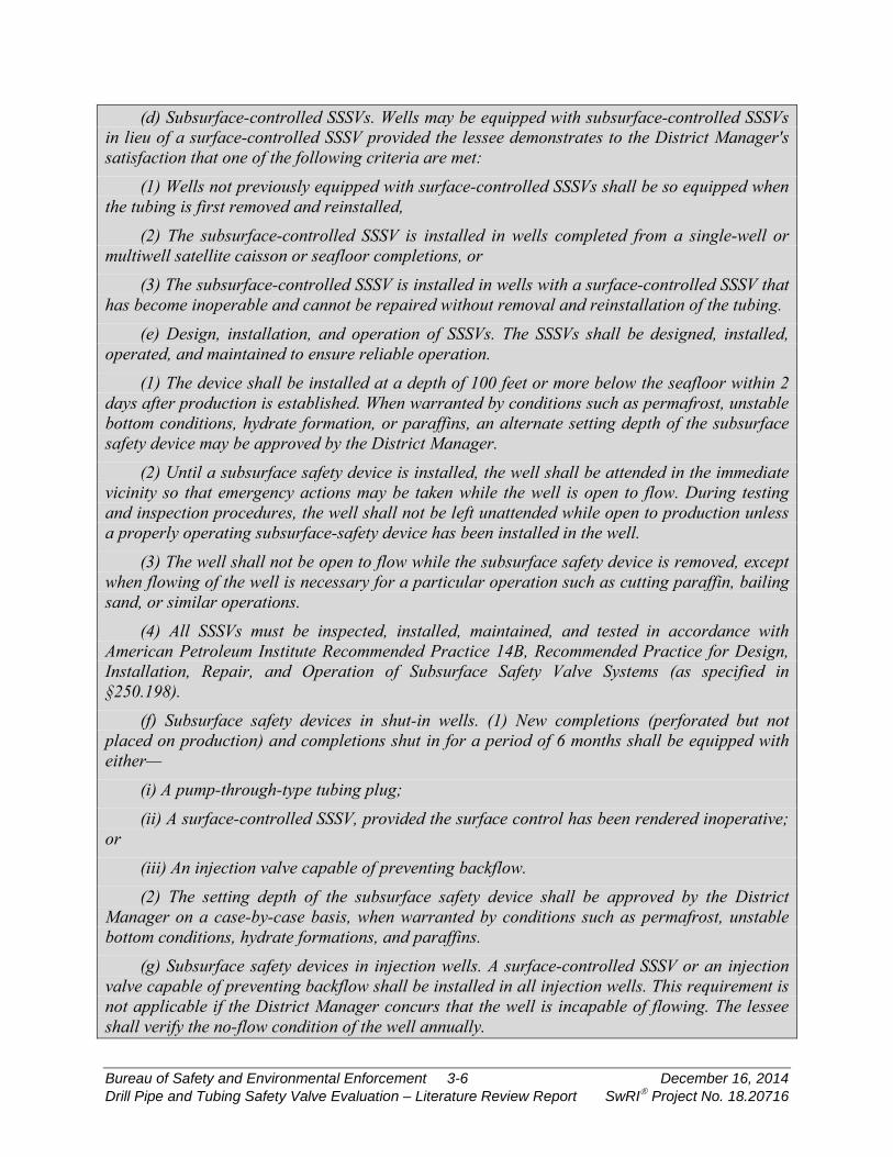
(d) Subsurface-controlled SSSVs. Wells may be equipped with subsurface-controlled SSSVs in lieu of a surface-controlled SSSV provided the lessee demonstrates to the District Manager's satisfaction that one of the following criteria are met:
(1) Wells not previously equipped with surface-controlled SSSVs shall be so equipped when the tubing is first removed and reinstalled,
(2) The subsurface-controlled SSSV is installed in wells completed from a single-well or multiwell satellite caisson or seafloor completions, or
(3) The subsurface-controlled SSSV is installed in wells with a surface-controlled SSSV that has become inoperable and cannot be repaired without removal and reinstallation of the tubing.
(e) Design, installation, and operation of SSSVs. The SSSVs shall be designed, installed, operated, and maintained to ensure reliable operation.
(1) The device shall be installed at a depth of 100 feet or more below the seafloor within 2 days after production is established. When warranted by conditions such as permafrost, unstable bottom conditions, hydrate formation, or paraffins, an alternate setting depth of the subsurface safety device may be approved by the District Manager.
(2) Until a subsurface safety device is installed, the well shall be attended in the immediate vicinity so that emergency actions may be taken while the well is open to flow. During testing and inspection procedures, the well shall not be left unattended while open to production unless a properly operating subsurface-safety device has been installed in the well.
(3) The well shall not be open to flow while the subsurface safety device is removed, except when flowing of the well is necessary for a particular operation such as cutting paraffin, bailing sand, or similar operations.
(4) All SSSVs must be inspected, installed, maintained, and tested in accordance with American Petroleum Institute Recommended Practice 14B, Recommended Practice for Design, Installation, Repair, and Operation of Subsurface Safety Valve Systems (as specified in §250.198).
(f) Subsurface safety devices in shut-in wells. (1) New completions (perforated but not placed on production) and completions shut in for a period of 6 months shall be equipped with either—
(i) A pump-through-type tubing plug; (ii) A surface-controlled SSSV, provided the surface control has been rendered inoperative;
or (iii) An injection valve capable of preventing backflow. (2) The setting depth of the subsurface safety device shall be approved by the District
Manager on a case-by-case basis, when warranted by conditions such as permafrost, unstable bottom conditions, hydrate formations, and paraffins.
(g) Subsurface safety devices in injection wells. A surface-controlled SSSV or an injection valve capable of preventing backflow shall be installed in all injection wells. This requirement is not applicable if the District Manager concurs that the well is incapable of flowing. The lessee shall verify the no-flow condition of the well annually.
Bureau of Safety and Environmental Enforcement 3-6 December 16, 2014 Drill Pipe and Tubing Safety Valve Evaluation – Literature Review Report SwRI Project No. 18.20716

(h) Temporary removal for routine operations. (1) Each wireline- or pumpdown-retrievable subsurface safety device may be removed, without further authorization or notice, for a routine operation which does not require the approval of a Form BSEE-0124, Application for Permit to Modify, in §250.601 of this part for a period not to exceed 15 days.
(2) The well shall be identified by a sign on the wellhead stating that the subsurface safety device has been removed. The removal of the subsurface safety device shall be noted in the records as required in §250.804(b) of this part. If the master valve is open, a trained person shall be in the immediate vicinity of the well to attend the well so that emergency actions may be taken, if necessary.
(3) A platform well shall be monitored, but a person need not remain in the well-bay area continuously if the master valve is closed. If the well is on a satellite structure, it must be attended or a pump-through plug installed in the tubing at least 100 feet below the mud line and the master valve closed, unless otherwise approved by the District Manager.
(4) The well shall not be allowed to flow while the subsurface safety device is removed, except when flowing the well is necessary for that particular operation. The provisions of this paragraph are not applicable to the testing and inspection procedures in §250.804 of this part.
(i) Additional safety equipment. All tubing installations in which a wireline- or pumpdown-retrievable subsurface safety device is installed after the effective date of this subpart shall be equipped with a landing nipple with flow couplings or other protective equipment above and below to provide for the setting of the SSSV. The control system for all surface-controlled SSSVs shall be an integral part of the platform Emergency Shutdown System (ESD). In addition to the activation of the ESD by manual action on the platform, the system may be activated by a signal from a remote location. Surface-controlled SSSVs shall close in response to shut-in signals from the ESD and in response to the fire loop or other fire detection devices.
(j) Emergency action. In the event of an emergency, such as an impending storm, any well not equipped with a subsurface safety device and which is capable of natural flow shall have the device properly installed as soon as possible with due consideration being given to personnel safety.
§250.803 Additional production system requirements. [Clauses not pertaining directly to subject removed for brevity.]
(ii) Closure of the SSV shall not exceed 45 seconds after automatic detection of an abnormal condition or actuation of an ESD. The surface-controlled SSSV shall close in not more than 2 minutes after the shut-in signal has closed the SSV. Design-delayed closure time greater than 2 minutes shall be justified by the lessee based on the individual well's mechanical/production characteristics and be approved by the District Manager.
Bureau of Safety and Environmental Enforcement 3-7 December 16, 2014 Drill Pipe and Tubing Safety Valve Evaluation – Literature Review Report SwRI Project No. 18.20716

§250.804 Production safety-system testing and records. (a) Inspection and testing. The safety-system devices shall be successfully inspected and
tested by the lessee at the interval specified below or more frequently if operating conditions warrant. Testing must be in accordance with API RP 14C, Appendix D (as incorporated by reference in §250.198), and the following:
(1) Testing requirements for subsurface safety devices are as follows: (i) Each surface-controlled subsurface safety device installed in a well, including such
devices in shut-in and injection wells, shall be tested in place for proper operation when installed or reinstalled and thereafter at intervals not exceeding 6 months. If the device does not operate properly, or if a liquid leakage rate in excess of 200 cubic centimeters per minute or a gas leakage rate in excess of 5 cubic feet per minute is observed, the device shall be removed, repaired and reinstalled, or replaced. Testing shall be in accordance with API RP 14B (as incorporated by reference in §250.198) to ensure proper operation.
(ii) Each subsurface-controlled SSSV installed in a well shall be removed, inspected, and repaired or adjusted, as necessary, and reinstalled or replaced at intervals not exceeding 6 months for those valves not installed in a landing nipple and 12 months for those valves installed in a landing nipple.
[Clauses not pertaining directly to subject removed for brevity.]
(11) The ESD shall be tested for operation at least once each calendar month, but at no time shall more than 6 weeks elapse between tests. The test shall be conducted by alternating ESD stations monthly to close at least one wellhead SSV and verify a surface-controlled SSSV closure for that well as indicated by control circuitry actuation.
§250.806 Safety and pollution prevention equipment quality assurance requirements. (a) General requirements. (1) Except as provided in paragraph (b)(1) of this section, you
may install only certified safety and pollution prevention equipment (SPPE) in wells located on the OCS. SPPE includes the following:
(i) Surface safety valves (SSV) and actuators; (ii) Underwater safety valves (USV) and actuators; and (iii) Subsurface safety valves (SSSV) and associated safety valve locks and landing nipples. (2) Certified SPPE is equipment the manufacturer certifies as manufactured under a quality
assurance program BSEE recognizes. BSEE considers all other SPPE as noncertified. BSEE recognizes two quality assurance programs:
(i) ANSI/ASME SPPE-1-1994 and SPPE-1d-1996 Addenda, Quality Assurance and Certification of Safety and Pollution Prevention Equipment Used in Offshore Oil and Gas Operations (as incorporated by reference in §250.198); and
(ii) API Spec Q1, Specification for Quality Programs for the Petroleum, Petrochemical and Natural Gas Industry (as incorporated by reference in §250.198).
Bureau of Safety and Environmental Enforcement 3-8 December 16, 2014 Drill Pipe and Tubing Safety Valve Evaluation – Literature Review Report SwRI Project No. 18.20716

(3) All SSV's and USV's must meet the technical specifications of API Spec 6A and 6AV1. All SSSVs must meet the technical specifications of API Specification 14A (as incorporated by reference in §250.198). However, SSSVs and related equipment planned to be used in high pressure high temperature environments must meet the additional requirements set forth in §250.807.
§250.807 Additional requirements for subsurface safety valves and related equipment installed in high pressure high temperature (HPHT) environments.
(a) If you plan to install SSSVs and related equipment in an HPHT environment, you must submit detailed information with your Application for Permit to Drill (APD), Application for Permit to Modify (APM), or Deepwater Operations Plan (DWOP) that demonstrates the SSSVs and related equipment are capable of performing in the applicable HPHT environment. Your detailed information must include the following:
(1) A discussion of the SSSVs' and related equipment's design verification analysis; (2) A discussion of the SSSVs' and related equipment's design validation and functional
testing process and procedures used; and (3) An explanation of why the analysis, process, and procedures ensure that the SSSVs and
related equipment are fit-for-service in the applicable HPHT environment. (b) For this section, HPHT environment means when one or more of the following well
conditions exist: (1) The completion of the well requires completion equipment or well control equipment
assigned a pressure rating greater than 15,000 psig or a temperature rating greater than 350 degrees Fahrenheit;
(2) The maximum anticipated surface pressure or shut-in tubing pressure is greater than 15,000 psig on the seafloor for a well with a subsea wellhead or at the surface for a well with a surface wellhead; or
(3) The flowing temperature is equal to or greater than 350 degrees Fahrenheit on the seafloor for a well with a subsea wellhead or at the surface for a well with a surface wellhead.
(c) For this section, related equipment includes wellheads, tubing heads, tubulars, packers, threaded connections, seals, seal assemblies, production trees, chokes, well control equipment, and any other equipment that will be exposed to the HPHT environment.
3.2.3 State Requirements Of the states reviewed for this project, four had specific requirements for SSSVs: Alaska,
California, Tennessee, and Texas.
Bureau of Safety and Environmental Enforcement 3-9 December 16, 2014 Drill Pipe and Tubing Safety Valve Evaluation – Literature Review Report SwRI Project No. 18.20716
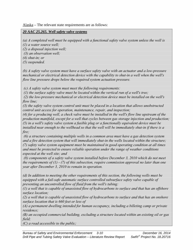
Alaska – The relevant state requirements are as follows:
20 AAC 25.265. Well safety valve systems (a) A completed well must be equipped with a functional safety valve system unless the well is (1) a water source well; (2) a disposal injection well; (3) an observation well; (4) shut-in; or (5) suspended. (b) A safety valve system must have a surface safety valve with an actuator and a low-pressure mechanical or electrical detection device with the capability to shut-in a well when the well's flow line pressure drops below the required system actuation pressure. (c) A safety valve system must meet the following requirements: (1) the surface safety valve must be located within the vertical run of a well's tree; (2) the low-pressure mechanical or electrical detection device must be installed on the well's flow line; (3) the safety valve system control unit must be placed in a location that allows unobstructed control unit access for operation, maintenance, repair, and inspection; (4) for a producing well, a check valve must be installed in the well's flow line upstream of the production manifold, except for a well that cycles between gas storage injection and production; (5) in a well's safety valve system a fusible plug or a functionally equivalent device must be installed near enough to the wellhead so that the well will be immediately shut-in if there is a fire; (6) a structure containing multiple wells in a common area must have a gas detection system and a fire detection system that will immediately shut-in the wells located within the structure; (7) safety valve system equipment must be maintained in good operating condition at all times and must be protected to ensure reliable operation under the range of weather conditions expected at the well site; and (8) components of a safety valve system installed before December 3, 2010 which do not meet the requirements of (1) - (7) of this subsection, require commission approval no later than one year after December 3, 2010 to remain in operation. (d) In addition to meeting the other requirements of this section, the following wells must be equipped with a fail-safe automatic surface controlled subsurface safety valve capable of preventing an uncontrolled flow of fluid from the well's tubing: (1) a well that is capable of unassisted flow of hydrocarbons to surface and that has an offshore surface location; (2) a well that is capable of unassisted flow of hydrocarbons to surface and that has an onshore surface location that is 660 feet or less of (A) a permanent dwelling intended for human occupancy, including a billeting camp or private residence; (B) an occupied commercial building, excluding a structure located within an existing oil or gas field; (C) a road accessible to the public;
Bureau of Safety and Environmental Enforcement 3-10 December 16, 2014 Drill Pipe and Tubing Safety Valve Evaluation – Literature Review Report SwRI Project No. 18.20716
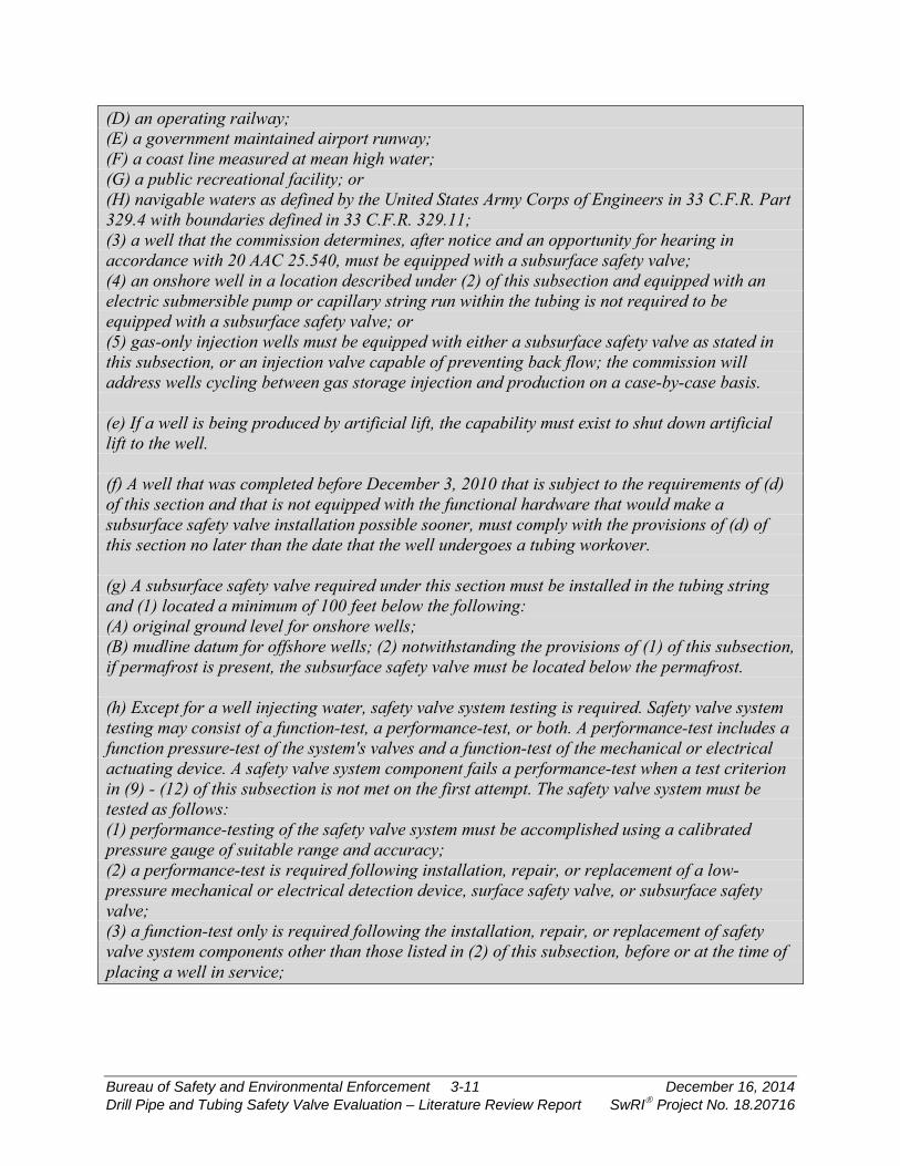
(D) an operating railway; (E) a government maintained airport runway; (F) a coast line measured at mean high water; (G) a public recreational facility; or (H) navigable waters as defined by the United States Army Corps of Engineers in 33 C.F.R. Part 329.4 with boundaries defined in 33 C.F.R. 329.11; (3) a well that the commission determines, after notice and an opportunity for hearing in accordance with 20 AAC 25.540, must be equipped with a subsurface safety valve; (4) an onshore well in a location described under (2) of this subsection and equipped with an electric submersible pump or capillary string run within the tubing is not required to be equipped with a subsurface safety valve; or (5) gas-only injection wells must be equipped with either a subsurface safety valve as stated in this subsection, or an injection valve capable of preventing back flow; the commission will address wells cycling between gas storage injection and production on a case-by-case basis. (e) If a well is being produced by artificial lift, the capability must exist to shut down artificial lift to the well. (f) A well that was completed before December 3, 2010 that is subject to the requirements of (d) of this section and that is not equipped with the functional hardware that would make a subsurface safety valve installation possible sooner, must comply with the provisions of (d) of this section no later than the date that the well undergoes a tubing workover. (g) A subsurface safety valve required under this section must be installed in the tubing string and (1) located a minimum of 100 feet below the following: (A) original ground level for onshore wells; (B) mudline datum for offshore wells; (2) notwithstanding the provisions of (1) of this subsection, if permafrost is present, the subsurface safety valve must be located below the permafrost. (h) Except for a well injecting water, safety valve system testing is required. Safety valve system testing may consist of a function-test, a performance-test, or both. A performance-test includes a function pressure-test of the system's valves and a function-test of the mechanical or electrical actuating device. A safety valve system component fails a performance-test when a test criterion in (9) - (12) of this subsection is not met on the first attempt. The safety valve system must be tested as follows: (1) performance-testing of the safety valve system must be accomplished using a calibrated pressure gauge of suitable range and accuracy; (2) a performance-test is required following installation, repair, or replacement of a low-pressure mechanical or electrical detection device, surface safety valve, or subsurface safety valve; (3) a function-test only is required following the installation, repair, or replacement of safety valve system components other than those listed in (2) of this subsection, before or at the time of placing a well in service;
Bureau of Safety and Environmental Enforcement 3-11 December 16, 2014 Drill Pipe and Tubing Safety Valve Evaluation – Literature Review Report SwRI Project No. 18.20716
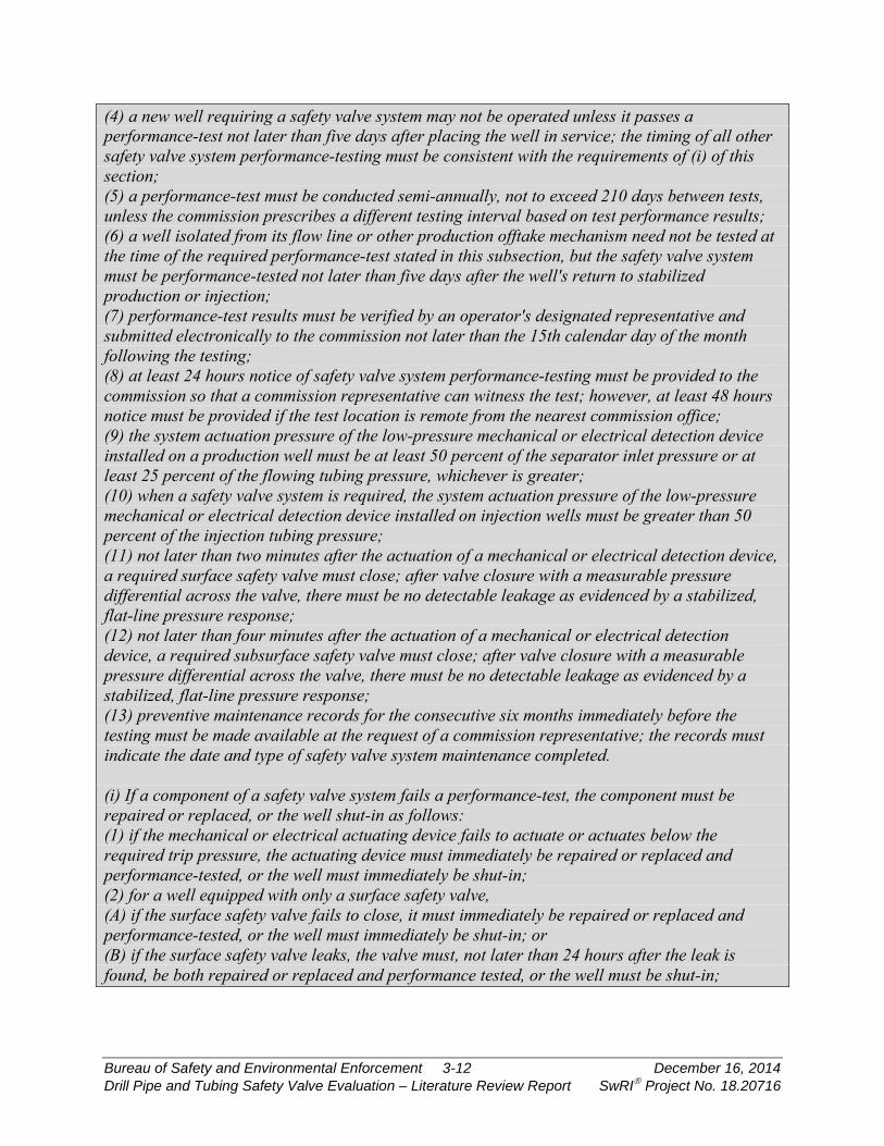
(4) a new well requiring a safety valve system may not be operated unless it passes a performance-test not later than five days after placing the well in service; the timing of all other safety valve system performance-testing must be consistent with the requirements of (i) of this section; (5) a performance-test must be conducted semi-annually, not to exceed 210 days between tests, unless the commission prescribes a different testing interval based on test performance results; (6) a well isolated from its flow line or other production offtake mechanism need not be tested at the time of the required performance-test stated in this subsection, but the safety valve system must be performance-tested not later than five days after the well's return to stabilized production or injection; (7) performance-test results must be verified by an operator's designated representative and submitted electronically to the commission not later than the 15th calendar day of the month following the testing; (8) at least 24 hours notice of safety valve system performance-testing must be provided to the commission so that a commission representative can witness the test; however, at least 48 hours notice must be provided if the test location is remote from the nearest commission office; (9) the system actuation pressure of the low-pressure mechanical or electrical detection device installed on a production well must be at least 50 percent of the separator inlet pressure or at least 25 percent of the flowing tubing pressure, whichever is greater; (10) when a safety valve system is required, the system actuation pressure of the low-pressure mechanical or electrical detection device installed on injection wells must be greater than 50 percent of the injection tubing pressure; (11) not later than two minutes after the actuation of a mechanical or electrical detection device, a required surface safety valve must close; after valve closure with a measurable pressure differential across the valve, there must be no detectable leakage as evidenced by a stabilized, flat-line pressure response; (12) not later than four minutes after the actuation of a mechanical or electrical detection device, a required subsurface safety valve must close; after valve closure with a measurable pressure differential across the valve, there must be no detectable leakage as evidenced by a stabilized, flat-line pressure response; (13) preventive maintenance records for the consecutive six months immediately before the testing must be made available at the request of a commission representative; the records must indicate the date and type of safety valve system maintenance completed. (i) If a component of a safety valve system fails a performance-test, the component must be repaired or replaced, or the well shut-in as follows: (1) if the mechanical or electrical actuating device fails to actuate or actuates below the required trip pressure, the actuating device must immediately be repaired or replaced and performance-tested, or the well must immediately be shut-in; (2) for a well equipped with only a surface safety valve, (A) if the surface safety valve fails to close, it must immediately be repaired or replaced and performance-tested, or the well must immediately be shut-in; or (B) if the surface safety valve leaks, the valve must, not later than 24 hours after the leak is found, be both repaired or replaced and performance tested, or the well must be shut-in;
Bureau of Safety and Environmental Enforcement 3-12 December 16, 2014 Drill Pipe and Tubing Safety Valve Evaluation – Literature Review Report SwRI Project No. 18.20716
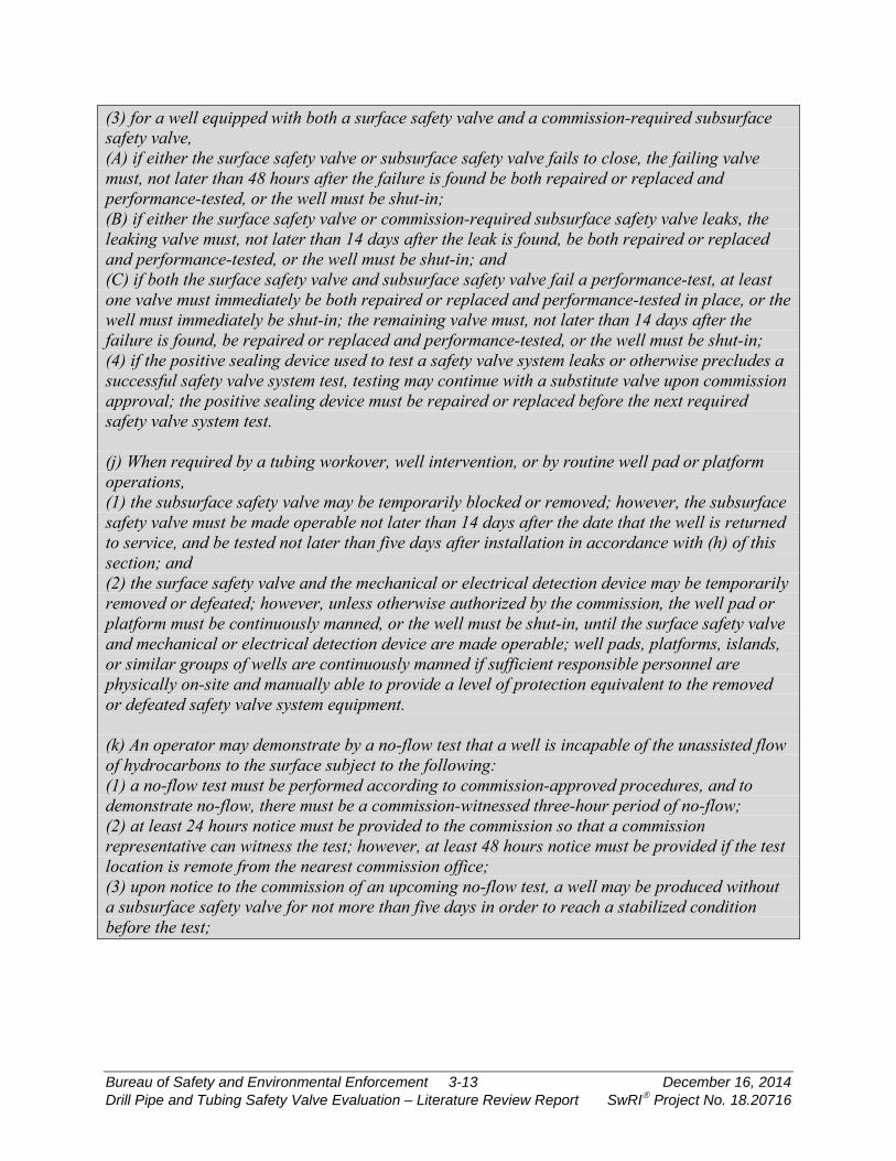
(3) for a well equipped with both a surface safety valve and a commission-required subsurface safety valve, (A) if either the surface safety valve or subsurface safety valve fails to close, the failing valve must, not later than 48 hours after the failure is found be both repaired or replaced and performance-tested, or the well must be shut-in; (B) if either the surface safety valve or commission-required subsurface safety valve leaks, the leaking valve must, not later than 14 days after the leak is found, be both repaired or replaced and performance-tested, or the well must be shut-in; and (C) if both the surface safety valve and subsurface safety valve fail a performance-test, at least one valve must immediately be both repaired or replaced and performance-tested in place, or the well must immediately be shut-in; the remaining valve must, not later than 14 days after the failure is found, be repaired or replaced and performance-tested, or the well must be shut-in; (4) if the positive sealing device used to test a safety valve system leaks or otherwise precludes a successful safety valve system test, testing may continue with a substitute valve upon commission approval; the positive sealing device must be repaired or replaced before the next required safety valve system test. (j) When required by a tubing workover, well intervention, or by routine well pad or platform operations, (1) the subsurface safety valve may be temporarily blocked or removed; however, the subsurface safety valve must be made operable not later than 14 days after the date that the well is returned to service, and be tested not later than five days after installation in accordance with (h) of this section; and (2) the surface safety valve and the mechanical or electrical detection device may be temporarily removed or defeated; however, unless otherwise authorized by the commission, the well pad or platform must be continuously manned, or the well must be shut-in, until the surface safety valve and mechanical or electrical detection device are made operable; well pads, platforms, islands, or similar groups of wells are continuously manned if sufficient responsible personnel are physically on-site and manually able to provide a level of protection equivalent to the removed or defeated safety valve system equipment. (k) An operator may demonstrate by a no-flow test that a well is incapable of the unassisted flow of hydrocarbons to the surface subject to the following: (1) a no-flow test must be performed according to commission-approved procedures, and to demonstrate no-flow, there must be a commission-witnessed three-hour period of no-flow; (2) at least 24 hours notice must be provided to the commission so that a commission representative can witness the test; however, at least 48 hours notice must be provided if the test location is remote from the nearest commission office; (3) upon notice to the commission of an upcoming no-flow test, a well may be produced without a subsurface safety valve for not more than five days in order to reach a stabilized condition before the test;
Bureau of Safety and Environmental Enforcement 3-13 December 16, 2014 Drill Pipe and Tubing Safety Valve Evaluation – Literature Review Report SwRI Project No. 18.20716
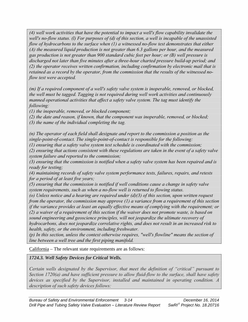
(4) well work activities that have the potential to impact a well's flow capability invalidate the well's no-flow status. (l) For purposes of (d) of this section, a well is incapable of the unassisted flow of hydrocarbons to the surface when (1) a witnessed no-flow test demonstrates that either (A) the measured liquid production is not greater than 6.3 gallons per hour, and the measured gas production is not greater than 900 standard cubic feet per hour; or (B) well pressure is discharged not later than five minutes after a three-hour charted pressure build-up period; and (2) the operator receives written confirmation, including confirmation by electronic mail that is retained as a record by the operator, from the commission that the results of the witnessed no-flow test were accepted. (m) If a required component of a well's safety valve system is inoperable, removed, or blocked, the well must be tagged. Tagging is not required during well work activities and continuously manned operational activities that affect a safety valve system. The tag must identify the following: (1) the inoperable, removed, or blocked component; (2) the date and reason, if known, that the component was inoperable, removed, or blocked; (3) the name of the individual completing the tag. (n) The operator of each field shall designate and report to the commission a position as the single-point-of-contact. The single-point-of-contact is responsible for the following: (1) ensuring that a safety valve system test schedule is coordinated with the commission; (2) ensuring that actions consistent with these regulations are taken in the event of a safety valve system failure and reported to the commission; (3) ensuring that the commission is notified when a safety valve system has been repaired and is ready for testing; (4) maintaining records of safety valve system performance tests, failures, repairs, and retests for a period of at least five years; (5) ensuring that the commission is notified if well conditions cause a change in safety valve system requirements, such as when a no-flow well is returned to flowing status. (o) Unless notice and a hearing are required under (d)(3) of this section, upon written request from the operator, the commission may approve (1) a variance from a requirement of this section if the variance provides at least an equally effective means of complying with the requirement; or (2) a waiver of a requirement of this section if the waiver does not promote waste, is based on sound engineering and geoscience principles, will not jeopardize the ultimate recovery of hydrocarbons, does not jeopardize correlative rights, and does not result in an increased risk to health, safety, or the environment, including freshwater. (p) In this section, unless the context otherwise requires, "well's flowline" means the section of line between a well tree and the first piping manifold.
California – The relevant state requirements are as follows:
1724.3. Well Safety Devices for Critical Wells. Certain wells designated by the Supervisor, that meet the definition of “critical” pursuant to Section 1720(a) and have sufficient pressure to allow fluid-flow to the surface, shall have safety devices as specified by the Supervisor, installed and maintained in operating condition. A description of such safety devices follows:
Bureau of Safety and Environmental Enforcement 3-14 December 16, 2014 Drill Pipe and Tubing Safety Valve Evaluation – Literature Review Report SwRI Project No. 18.20716

(a) Surface safety devices. (1) Fail-close, well shut-in or shut-down devices. Wellhead assemblies shall be equipped with an automatic fail-close valve. For shut-in wells capable of flowing, a tubing plug may be installed in lieu of a subsurface tubing safety valve. Subsurface safety devices shall be installed, adjusted, and maintained to ensure reliable operation. If for any reason a subsurface safety device is removed from a well, a replacement subsurface safety device or tubing plug shall be promptly installed. Any well in which a subsurface safety device or tubing plug is installed shall have the tubing-casing annulus sealed at or below the valve- or plug-setting depth. A bypass-type packer that will seal the annulus on manual or automatic operation of the tubing subsurface safety device will meet this requirement.
1724.4. Testing and Inspection of Safety Devices. (a) All installed well safety devices, required pursuant to Section 1724.3 of this article, shall be tested at least every six (6) months, as follows: (1) Flow line pressure sensors shall be tested for proper pressure settings. (2) Automatic wellhead safety valves shall be tested for reliable operation and holding pressure. (3) Subsurface safety devices shall be tested for reliable operation. (4) Tubing plugs or packers shall be tested for holding pressure. (b) The appropriate Division district office shall be notified before such tests are made, as these tests may be witnessed by a Division inspector. Test failures not immediately repaired or corrected and not witnessed by a Division inspector shall be reported to the Division within 24 hours. (c) The Supervisor may establish a special testing schedule for safety devices other than that specified in this section, based upon equipment performance or special conditions. (d) The operator shall maintain records, available to Division personnel during business hours, showing the present status and history of each well safety device installed, including dates, details and results of inspections, tests, repairs, reinstallations, and replacements.
1747. Safety and Pollution Control. Operators shall equip wells and associated facilities with necessary safety devices and establish procedures as follows: (a) Subsurface safety device. All wells capable of flowing oil or gas to the ocean floor shall be equipped with a surface controlled subsurface tubing safety valve installed at a depth of 100 feet or more below the ocean floor. Such device shall be installed in all oil and gas wells, including artificial lift wells, unless proofs provided to the Supervisor that such wells are incapable of any natural flow to the ocean floor. For shut-in wells capable of flowing oil or gas, a tubing plug may be installed, in lieu of a subsurface safety device, and such plug shall also be installed when required by the Supervisor. (b) Subsurface safety devices shall be adjusted, installed, and maintained to insure reliable operation. When a subsurface safety device is removed from a well for repair or replacement, a standby subsurface safety device or tubing plug shall be available at the well location, and shall be immediately installed within the limits of practicability, consideration being given to time, equipment, and personnel safety. All wells in which subsurface safety device or tubing plug is installed shall have the tubing-casing annulus sealed below the valve or plug setting depth.
Bureau of Safety and Environmental Enforcement 3-15 December 16, 2014 Drill Pipe and Tubing Safety Valve Evaluation – Literature Review Report SwRI Project No. 18.20716
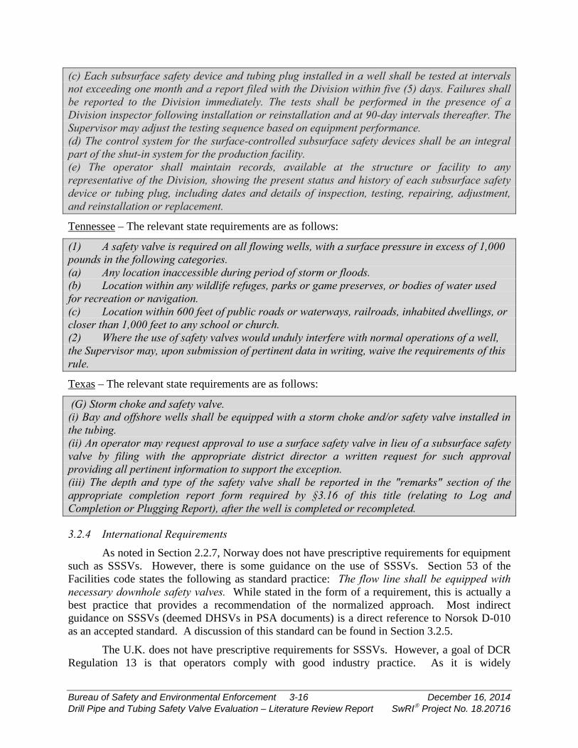
(c) Each subsurface safety device and tubing plug installed in a well shall be tested at intervals not exceeding one month and a report filed with the Division within five (5) days. Failures shall be reported to the Division immediately. The tests shall be performed in the presence of a Division inspector following installation or reinstallation and at 90-day intervals thereafter. The Supervisor may adjust the testing sequence based on equipment performance. (d) The control system for the surface-controlled subsurface safety devices shall be an integral part of the shut-in system for the production facility. (e) The operator shall maintain records, available at the structure or facility to any representative of the Division, showing the present status and history of each subsurface safety device or tubing plug, including dates and details of inspection, testing, repairing, adjustment, and reinstallation or replacement.
Tennessee – The relevant state requirements are as follows:
(1) A safety valve is required on all flowing wells, with a surface pressure in excess of 1,000 pounds in the following categories. (a) Any location inaccessible during period of storm or floods. (b) Location within any wildlife refuges, parks or game preserves, or bodies of water used for recreation or navigation. (c) Location within 600 feet of public roads or waterways, railroads, inhabited dwellings, or closer than 1,000 feet to any school or church. (2) Where the use of safety valves would unduly interfere with normal operations of a well, the Supervisor may, upon submission of pertinent data in writing, waive the requirements of this rule.
Texas – The relevant state requirements are as follows:
(G) Storm choke and safety valve. (i) Bay and offshore wells shall be equipped with a storm choke and/or safety valve installed in the tubing. (ii) An operator may request approval to use a surface safety valve in lieu of a subsurface safety valve by filing with the appropriate district director a written request for such approval providing all pertinent information to support the exception. (iii) The depth and type of the safety valve shall be reported in the "remarks" section of the appropriate completion report form required by §3.16 of this title (relating to Log and Completion or Plugging Report), after the well is completed or recompleted.
3.2.4 International Requirements As noted in Section 2.2.7, Norway does not have prescriptive requirements for equipment
such as SSSVs. However, there is some guidance on the use of SSSVs. Section 53 of the Facilities code states the following as standard practice: The flow line shall be equipped with necessary downhole safety valves. While stated in the form of a requirement, this is actually a best practice that provides a recommendation of the normalized approach. Most indirect guidance on SSSVs (deemed DHSVs in PSA documents) is a direct reference to Norsok D-010 as an accepted standard. A discussion of this standard can be found in Section 3.2.5.
The U.K. does not have prescriptive requirements for SSSVs. However, a goal of DCR Regulation 13 is that operators comply with good industry practice. As it is widely
Bureau of Safety and Environmental Enforcement 3-16 December 16, 2014 Drill Pipe and Tubing Safety Valve Evaluation – Literature Review Report SwRI Project No. 18.20716
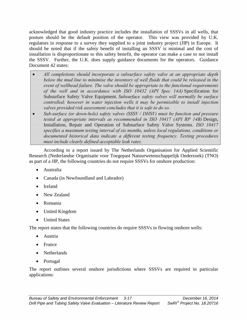
acknowledged that good industry practice includes the installation of SSSVs in all wells, that posture should be the default position of the operator. This view was provided by U.K. regulators in response to a survey they supplied to a joint industry project (JIP) in Europe. It should be noted that if the safety benefit of installing an SSSV is minimal and the cost of installation is disproportionate to this safety benefit, the operator can make a case to not install the SSSV. Further, the U.K. does supply guidance documents for the operators. Guidance Document 42 states:
• All completions should incorporate a subsurface safety valve at an appropriate depth below the mud line to minimise the inventory of well fluids that could be released in the event of wellhead failure. The valve should be appropriate to the functional requirements of the well and in accordance with ISO 10432 (API Spec 14A) Specification for Subsurface Safety Valve Equipment. Subsurface safety valves will normally be surface controlled; however in water injection wells it may be permissible to install injection valves provided risk assessment concludes that it is safe to do so.
• Sub-surface (or down-hole) safety valves (SSSV / DHSV) must be function and pressure tested at appropriate intervals as recommended in ISO 10417 (API RP 14B) Design, Installation, Repair and Operation of Subsurface Safety Valve Systems. ISO 10417 specifies a maximum testing interval of six months, unless local regulations, conditions or documented historical data indicate a different testing frequency. Testing procedures must include clearly defined acceptable leak rates.
According to a report issued by The Netherlands Organisation for Applied Scientific Research (Nederlandse Organisatie voor Toegepast Natuurwetenschappelijk Onderzoek) (TNO) as part of a JIP, the following countries do not require SSSVs for onshore production:
• Australia
• Canada (in Newfoundland and Labrador)
• Ireland
• New Zealand
• Romania
• United Kingdom
• United States The report states that the following countries do require SSSVs in flowing onshore wells:
• Austria
• France
• Netherlands
• Portugal The report outlines several onshore jurisdictions where SSSVs are required in particular applications:
Bureau of Safety and Environmental Enforcement 3-17 December 16, 2014 Drill Pipe and Tubing Safety Valve Evaluation – Literature Review Report SwRI Project No. 18.20716

• Canada (Alberta) – required in H2S wells, wells near dwellings, and walls with more than 140,000 m3 of production.
• Germany – required in most areas for wells capable of flow, regardless of whether or not they are actively flowing.
• Poland – required in H2S wells.
3.2.5 Standards Overview The two overarching standards for SSSVs are API Specification 14A (also branded as
ISO 10432) and API Recommended Practice 14B (also branded as ISO 10417). In this report, these documents will be referred to as API 14A and API 14B. Verification and validation requirements are elements of API 14A, while field testing, failure identification, reporting, and remediation are topics covered by API 14B.
At the writing of this report, both documents are undergoing significant revisions. The current active version of API 14A is the 11th edition and this edition is specifically cited in the CFR. This document has recently been revised to the 12th edition. The new version has been approved by API membership and is awaiting publication pending final edits. This update of the document contains significant changes to verification and validation requirements, so it will be prudent to discuss both the 11th and 12th editions to provide context to current practices and possible future direction of requirements for these products.
Similarly, API 14B is being revised from the 5th edition to the 6th edition. At the writing of this report, a completed version is being reviewed by the voting community in API with ballots due in January. It is very likely that the current balloted version will have further changes due to the voting process. This report will discuss the 5th edition and the balloted version of the 6th edition. Further edits to the 6th edition will be reflected in future project documents.
The third standard that will be discussed in this section of the report is Norsok D-010 (revision 4). This standard is called out in guidance documents from Norway’s PSA, so it serves as a de facto set of requirements for Norwegian waters.
API 14A
API 14A is a comprehensive document that covers everything from well parameters to be considered during design to raw material and heat-treating equipment qualification. For purposes of this project, the two key areas relevant to regulations are the verification and validation requirements.
The 11th edition of API 14A only contains one requirement for verification. Clause 6.4 (Design Verification) reads:
Design verification shall be performed to ensure that each SSSV design meets the supplier’s/manufacturer’s technical specifications. Design verification includes activities such as design reviews, design calculations, physical tests, comparison with similar designs and historical records of defined operating conditions.
The verification requirements in the 12th edition have been significantly strengthened. The Verification section (6.4) starts out similarly to the 11th editions:
Bureau of Safety and Environmental Enforcement 3-18 December 16, 2014 Drill Pipe and Tubing Safety Valve Evaluation – Literature Review Report SwRI Project No. 18.20716

Design verification shall be performed using documented procedures to ensure that each SSSV and secondary tool design meets the supplier/manufacturer's technical specifications and shall include activities such as design reviews, design calculations, physical tests, comparison with similar designs and historical records of defined operating conditions. Verification results shall be reviewed and approved by a qualified person and records of the review shall become a portion of the design documentation.
The document then provides guidance on design assumptions and design analysis. This text includes discussing methods such as:
• Distortion energy theory
• Triaxial yield equations
• Finite element analysis
• Computational fluid dynamics
There is additional discussion on rated performance envelopes. The new edition contains an annex related to HPHT equipment. This annex contains additional verification requirements for HPHT equipment:
a) The user/purchaser shall determine the maximum anticipated shut-in tubing pressure (SITP) at the SSSV.
b) The user/purchaser shall specify the RWP to be greater than the SITP. c) The SSSV shall conform to the requirements of 6.4 and the following additional
requirements: 1) For all metallic components integral to the tubing string and closure mechanism, perform an
elastic-plastic FEA using ASME BPVC Section VIII, Div 2 clause 5.2.4 using the supplier/manufacturer documented design margins and load factors. These FEA methods require a true stress true strain curve developed using ASME BPVC Section VIII, Div 2, Annex 3.D or Section VIII, Div 3, Para. KD-231.4 or via piece-wise linear fit of the test data. The data shall be obtained via testing per ASTM E21.
2) Localized stress discontinuities and localized yielding shall be evaluated by a qualified person to determine if the design is acceptable or if additional analysis is required;
3) When FEA has identified plastic strain in excess of 0.2%, a ratcheting analysis shall be performed per ASME Boiler and Pressure Vessel Code Section VIII: Division 3, KD-234 or ASME BPVC Section VIII, Div 2 clause 5.5.7.
4) Perform a fatigue screening per ASME Section VIII, Div 2 Para. 5.5.2. If the design exhibits fatigue sensitivity, conduct a fatigue analysis per API 579/ASME FFS-1 using a safety factor of 2 on anticipated operating life.
NOTE Load cases to be used in the fatigue screening are provided in the functional specification. d) The supplier/manufacturer shall perform combined loading analysis and generate the rated
performance envelope (see Annex M).
In regards to validation, the 11th edition, Annex B, contains testing requirements for Class 1 (freshwater) and Class 2 (sand slurry) services. The testing is required to be performed at an independent test agency. Successful compliance to the testing requirements also automatically qualifies all SSSVs of the same size, type, and model. The test can also be applied
Bureau of Safety and Environmental Enforcement 3-19 December 16, 2014 Drill Pipe and Tubing Safety Valve Evaluation – Literature Review Report SwRI Project No. 18.20716
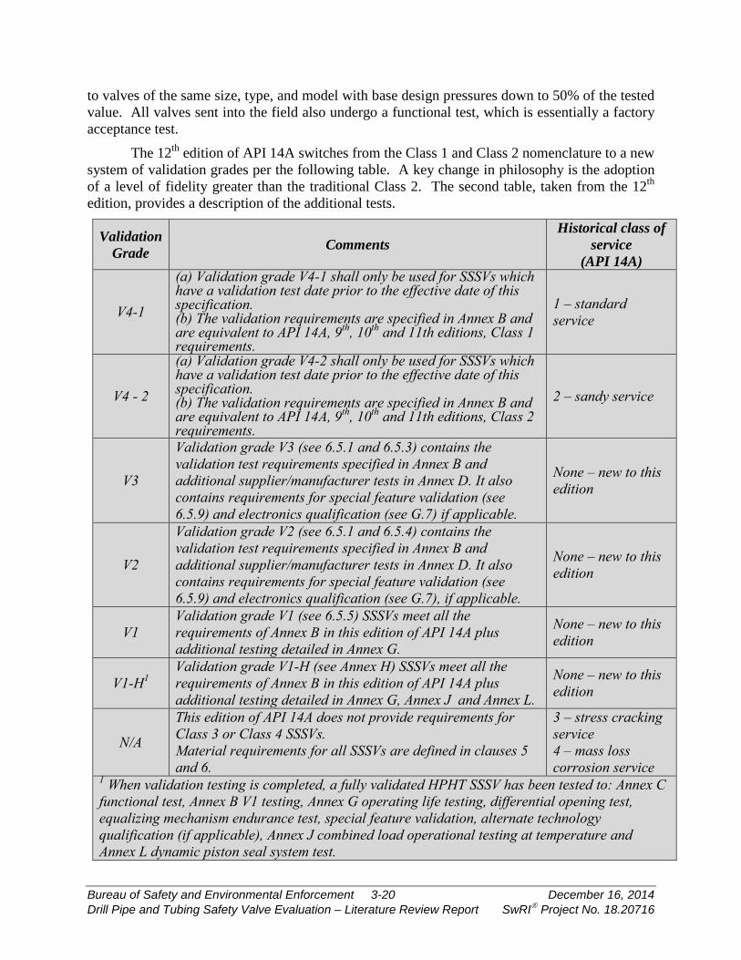
to valves of the same size, type, and model with base design pressures down to 50% of the tested value. All valves sent into the field also undergo a functional test, which is essentially a factory acceptance test.
The 12th edition of API 14A switches from the Class 1 and Class 2 nomenclature to a new system of validation grades per the following table. A key change in philosophy is the adoption of a level of fidelity greater than the traditional Class 2. The second table, taken from the 12th edition, provides a description of the additional tests.
Validation Grade Comments
Historical class of service
(API 14A)
V4-1
(a) Validation grade V4-1 shall only be used for SSSVs which have a validation test date prior to the effective date of this specification. (b) The validation requirements are specified in Annex B and are equivalent to API 14A, 9th, 10th and 11th editions, Class 1 requirements.
1 – standard service
V4 - 2
(a) Validation grade V4-2 shall only be used for SSSVs which have a validation test date prior to the effective date of this specification. (b) The validation requirements are specified in Annex B and are equivalent to API 14A, 9th, 10th and 11th editions, Class 2 requirements.
2 – sandy service
V3
Validation grade V3 (see 6.5.1 and 6.5.3) contains the validation test requirements specified in Annex B and additional supplier/manufacturer tests in Annex D. It also contains requirements for special feature validation (see 6.5.9) and electronics qualification (see G.7) if applicable.
None – new to this edition
V2
Validation grade V2 (see 6.5.1 and 6.5.4) contains the validation test requirements specified in Annex B and additional supplier/manufacturer tests in Annex D. It also contains requirements for special feature validation (see 6.5.9) and electronics qualification (see G.7), if applicable.
None – new to this edition
V1 Validation grade V1 (see 6.5.5) SSSVs meet all the requirements of Annex B in this edition of API 14A plus additional testing detailed in Annex G.
None – new to this edition
V1-H1 Validation grade V1-H (see Annex H) SSSVs meet all the requirements of Annex B in this edition of API 14A plus additional testing detailed in Annex G, Annex J and Annex L.
None – new to this edition
N/A
This edition of API 14A does not provide requirements for Class 3 or Class 4 SSSVs. Material requirements for all SSSVs are defined in clauses 5 and 6.
3 – stress cracking service 4 – mass loss corrosion service
1 When validation testing is completed, a fully validated HPHT SSSV has been tested to: Annex C functional test, Annex B V1 testing, Annex G operating life testing, differential opening test, equalizing mechanism endurance test, special feature validation, alternate technology qualification (if applicable), Annex J combined load operational testing at temperature and Annex L dynamic piston seal system test.
Bureau of Safety and Environmental Enforcement 3-20 December 16, 2014 Drill Pipe and Tubing Safety Valve Evaluation – Literature Review Report SwRI Project No. 18.20716

Annex identification Annex title General description
of content Purpose
E
Alternative requirements for closure mechanism minimal leakage
Provides alternative leakage criteria for the functional test
Provides more stringent leak rate acceptance criteria
I Extended Sand Endurance Testing
Enhanced sand endurance testing
Evaluates the ability of the valve design to close and seal in sandy conditions
J Combined Loads Operational Test
Validation of closed end rated performance envelope limits
Confirms the ability of the SSSV to operate at the limits of the performance envelope
K Gas Slam Closure Testing
Testing requirements for high-rate slam closures
Evaluates closure of SSSV in increased flow rate gas wells.
L Dynamic seal system test
Testing requirements for primary dynamic seal systems at intermediate positions at static conditions
Evaluates gas sealing integrity of the dynamic seal system.
API 14B
API 14B provides guidance to operators on the installation, testing, and repair of SSSVs in the field. The most-relevant aspect of this document to the nature of this study is the testing requirement and, in particular, the allowable leakage rates during such a test. The requirements for the 5th edition (the currently-active version) of the document are provided in the following few paragraphs.
The opening and closing hydraulic pressures, mechanical actuation, closure-mechanism integrity and other features shall be verified according to the manufacturer’s operating manual prior to valve installation. After installation of the SCSSV in the well, the SCSSV shall be closed under minimum or no-flow conditions by operation of the surface control system. Verification of closure operation may be accomplished by pressure build-up/in-flow test. The SCSSV can be tested for leakage by opening the surface valves to check for flow. The SCSSV is reopened following the procedures in the manufacturer’s operating manual. SCSSVs shall be tested by closure-mechanism operation to verify the rate of leakage through the closure mechanism at a maximum interval of every six months unless local regulations, conditions and/or documented historical data indicate a different testing frequency. Leakage rates exceeding 400 cm3/min (13.5 oz/min) of liquid or 0.43 m3/min (15 scfm) of test gas shall be cause for test rejection and corrective action shall be taken to meet the requirements of this International Standard. Methods other than volumetric determination of leakage may be used, provided they are verifiable and repeatable. Example procedures for testing of an in situ SCSSV are provided in Annex E, which confirm fail-safe operation.
Bureau of Safety and Environmental Enforcement 3-21 December 16, 2014 Drill Pipe and Tubing Safety Valve Evaluation – Literature Review Report SwRI Project No. 18.20716
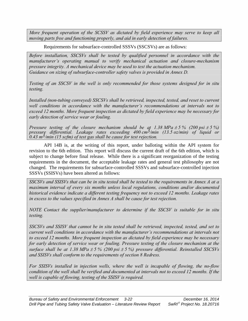
More frequent operation of the SCSSV as dictated by field experience may serve to keep all moving parts free and functioning properly, and aid in early detection of failures.
Requirements for subsurface-controlled SSSVs (SSCSVs) are as follows:
Before installation, SSCSVs shall be tested by qualified personnel in accordance with the manufacturer’s operating manual to verify mechanical actuation and closure-mechanism pressure integrity. A mechanical device may be used to test the actuation mechanism. Guidance on sizing of subsurface-controller safety valves is provided in Annex D. Testing of an SSCSV in the well is only recommended for those systems designed for in situ testing. Installed (non-tubing conveyed) SSCSVs shall be retrieved, inspected, tested, and reset to current well conditions in accordance with the manufacturer’s recommendations at intervals not to exceed 12 months. More frequent inspection as dictated by field experience may be necessary for early detection of service wear or fouling. Pressure testing of the closure mechanism should be at 1.38 MPa ± 5 % (200 psi ± 5 %) pressure differential. Leakage rates exceeding 400 cm3/min (13.5 oz/min) of liquid or 0.43 m3/min (15 scfm) of test gas shall be cause for test rejection.
API 14B is, at the writing of this report, under balloting within the API system for revision to the 6th edition. This report will discuss the current draft of the 6th edition, which is subject to change before final release. While there is a significant reorganization of the testing requirements in the document, the acceptable leakage rates and general test philosophy are not changed. The requirements for subsurface-controlled SSSVs and subsurface-controlled injection SSSVs (SSISVs) have been altered as follows:
SSCSVs and SSISVs that can be in situ tested shall be tested to the requirements in Annex A at a maximum interval of every six months unless local regulations, conditions and/or documented historical evidence indicate a different testing frequency not to exceed 12 months. Leakage rates in excess to the values specified in Annex A shall be cause for test rejection. NOTE Contact the supplier/manufacturer to determine if the SSCSV is suitable for in situ testing. SSCSVs and SSISV that cannot be in situ tested shall be retrieved, inspected, tested, and set to current well conditions in accordance with the manufacturer’s recommendations at intervals not to exceed 12 months. More frequent inspection as dictated by field experience may be necessary for early detection of service wear or fouling. Pressure testing of the closure mechanism at the surface shall be at 1.38 MPa ± 5 % (200 psi ± 5 %) pressure differential. Reinstalled SSCSVs and SSISVs shall conform to the requirements of section 8 Redress. For SSISVs installed in injection wells, where the well is incapable of flowing, the no-flow condition of the well shall be verified and documented at intervals not to exceed 12 months. If the well is capable of flowing, testing of the SSISV is required.
Bureau of Safety and Environmental Enforcement 3-22 December 16, 2014 Drill Pipe and Tubing Safety Valve Evaluation – Literature Review Report SwRI Project No. 18.20716

Norsok D-010
This document provides guidance on equipment used for well integrity, including SSSVs. This document references API 14A and API 14B for many requirements. In general, the few requirements presented in Norsok D-010 for SSSVs mimic those in API 14A and API 14B. Some specific differences in the documents are:
• Norsok D-010 requires that the SSSV validation includes five slam closures where at least two are at the maximum theoretical production rate of the well in which the valve is to be installed. API 14A utilizes four closures of a prescribed rate linked to the nominal size of the valve.
• Once installed in the well, Norsok D-010 states that the valve should be tested at both a low (1,000 psi) and high (undefined) differential pressure.
• Norsok D-0101 suggests increased testing intervals when the SSSV is exposed to high velocities or abrasive fluids.
The testing requirements once in service according to Norsok D-010 should be:
1. The valve shall be leak tested at specified regular intervals as follows: a. Monthly, until three consecutive qualified tests have been performed; thereafter b. Every three months, until three consecutive qualified tests have been performed; thereafter c. Every six months; d. Test evaluation period is volume and compressibility dependent and shall be held for a period that will give measureable pressure change for the allowed leak rate, minimum 30 min. 2. Acceptance of downhole safety valve tests shall meet the following ANSI/API RP 14B requirements: a. 0.42 Sm3/min (25.5 Sm3/hr) (900 scf/hr) for gas; b. 0.4 l/min (6.3 gal/hr) for liquid. 3. If the leak rate cannot be measured directly, indirect measurement by pressure monitoring of an enclosed volume downstream of the valve should be performed. 4. The emergency shutdown function shall be tested yearly. It shall be verified acceptable shut down time and that the valve closes on signal.
3.3 Kelly Valves
3.3.1 Overall Equipment Summary This section discusses the high-level requirements noted in Section 3.1 across all
regulations and standards studied for this product. The subsequent sections provide the detailed content for federal, state, and international regulations, as well as equipment standards.
Bureau of Safety and Environmental Enforcement 3-23 December 16, 2014 Drill Pipe and Tubing Safety Valve Evaluation – Literature Review Report SwRI Project No. 18.20716
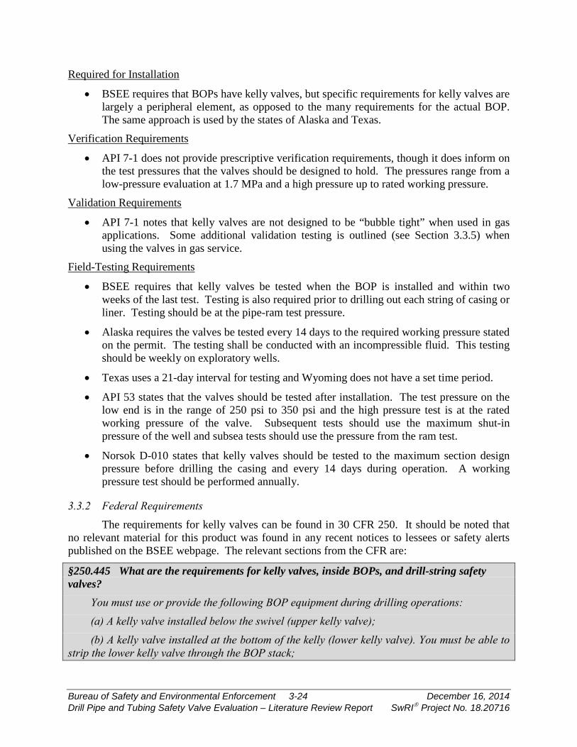
Required for Installation
• BSEE requires that BOPs have kelly valves, but specific requirements for kelly valves are largely a peripheral element, as opposed to the many requirements for the actual BOP. The same approach is used by the states of Alaska and Texas.
Verification Requirements
• API 7-1 does not provide prescriptive verification requirements, though it does inform on the test pressures that the valves should be designed to hold. The pressures range from a low-pressure evaluation at 1.7 MPa and a high pressure up to rated working pressure.
Validation Requirements
• API 7-1 notes that kelly valves are not designed to be “bubble tight” when used in gas applications. Some additional validation testing is outlined (see Section 3.3.5) when using the valves in gas service.
Field-Testing Requirements
• BSEE requires that kelly valves be tested when the BOP is installed and within two weeks of the last test. Testing is also required prior to drilling out each string of casing or liner. Testing should be at the pipe-ram test pressure.
• Alaska requires the valves be tested every 14 days to the required working pressure stated on the permit. The testing shall be conducted with an incompressible fluid. This testing should be weekly on exploratory wells.
• Texas uses a 21-day interval for testing and Wyoming does not have a set time period.
• API 53 states that the valves should be tested after installation. The test pressure on the low end is in the range of 250 psi to 350 psi and the high pressure test is at the rated working pressure of the valve. Subsequent tests should use the maximum shut-in pressure of the well and subsea tests should use the pressure from the ram test.
• Norsok D-010 states that kelly valves should be tested to the maximum section design pressure before drilling the casing and every 14 days during operation. A working pressure test should be performed annually.
3.3.2 Federal Requirements The requirements for kelly valves can be found in 30 CFR 250. It should be noted that
no relevant material for this product was found in any recent notices to lessees or safety alerts published on the BSEE webpage. The relevant sections from the CFR are:
§250.445 What are the requirements for kelly valves, inside BOPs, and drill-string safety valves?
You must use or provide the following BOP equipment during drilling operations: (a) A kelly valve installed below the swivel (upper kelly valve); (b) A kelly valve installed at the bottom of the kelly (lower kelly valve). You must be able to
strip the lower kelly valve through the BOP stack;
Bureau of Safety and Environmental Enforcement 3-24 December 16, 2014 Drill Pipe and Tubing Safety Valve Evaluation – Literature Review Report SwRI Project No. 18.20716
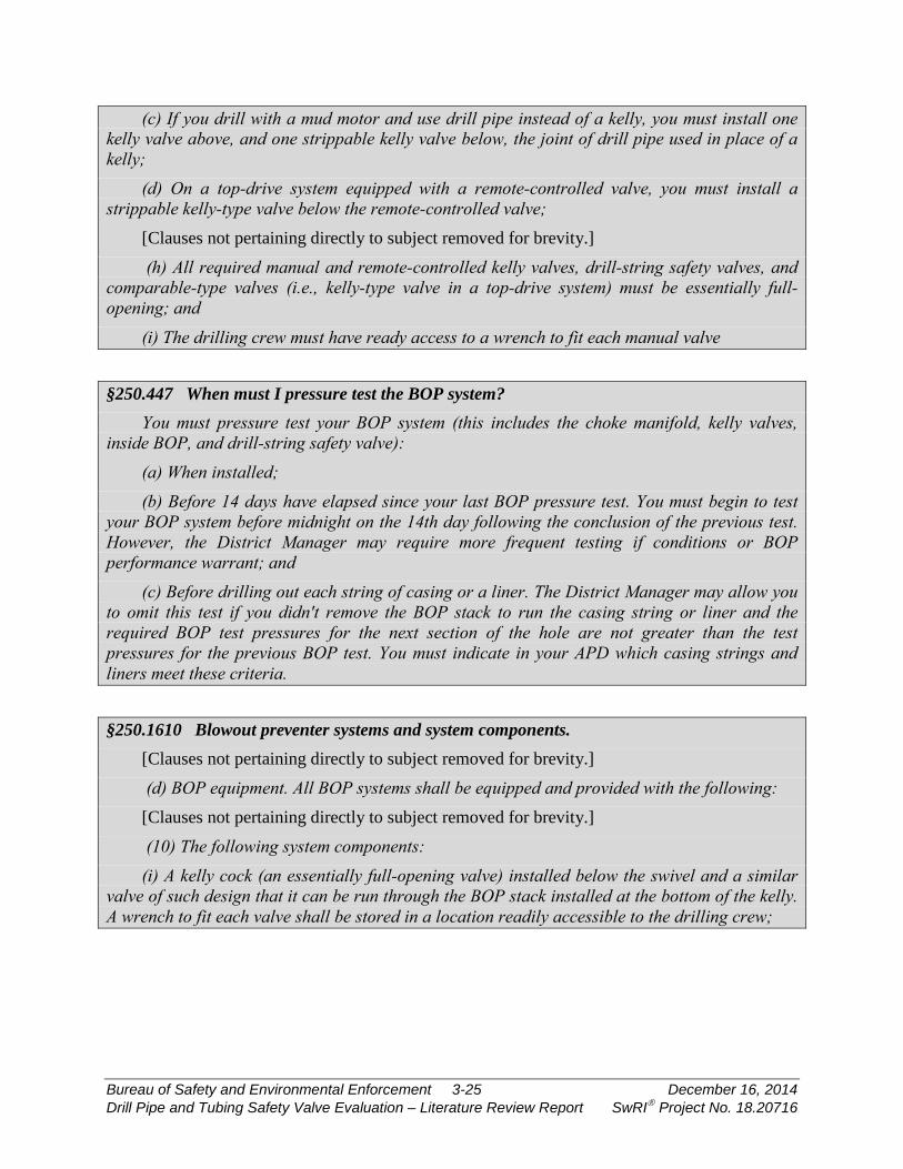
(c) If you drill with a mud motor and use drill pipe instead of a kelly, you must install one kelly valve above, and one strippable kelly valve below, the joint of drill pipe used in place of a kelly;
(d) On a top-drive system equipped with a remote-controlled valve, you must install a strippable kelly-type valve below the remote-controlled valve;
[Clauses not pertaining directly to subject removed for brevity.]
(h) All required manual and remote-controlled kelly valves, drill-string safety valves, and comparable-type valves (i.e., kelly-type valve in a top-drive system) must be essentially full-opening; and
(i) The drilling crew must have ready access to a wrench to fit each manual valve
§250.447 When must I pressure test the BOP system? You must pressure test your BOP system (this includes the choke manifold, kelly valves,
inside BOP, and drill-string safety valve): (a) When installed; (b) Before 14 days have elapsed since your last BOP pressure test. You must begin to test
your BOP system before midnight on the 14th day following the conclusion of the previous test. However, the District Manager may require more frequent testing if conditions or BOP performance warrant; and
(c) Before drilling out each string of casing or a liner. The District Manager may allow you to omit this test if you didn't remove the BOP stack to run the casing string or liner and the required BOP test pressures for the next section of the hole are not greater than the test pressures for the previous BOP test. You must indicate in your APD which casing strings and liners meet these criteria.
§250.1610 Blowout preventer systems and system components. [Clauses not pertaining directly to subject removed for brevity.]
(d) BOP equipment. All BOP systems shall be equipped and provided with the following: [Clauses not pertaining directly to subject removed for brevity.]
(10) The following system components: (i) A kelly cock (an essentially full-opening valve) installed below the swivel and a similar
valve of such design that it can be run through the BOP stack installed at the bottom of the kelly. A wrench to fit each valve shall be stored in a location readily accessible to the drilling crew;
Bureau of Safety and Environmental Enforcement 3-25 December 16, 2014 Drill Pipe and Tubing Safety Valve Evaluation – Literature Review Report SwRI Project No. 18.20716

§250.1611 Blowout preventer systems tests, actuations, inspections, and maintenance. [Clauses not pertaining directly to subject removed for brevity.]
(c) In conjunction with the weekly pressure test of BOP systems required in paragraph (d) of this section, the choke manifold valves, upper and lower kelly cocks, and drill-string safety valves shall be pressure tested to pipe-ram test pressures. Safety valves with proper casing connections shall be actuated prior to running casing.
(d) BOP system shall be pressure tested as follows: (1) When installed; (2) Before drilling out each string of casing or before continuing operations in cases where
cement is not drilled out; (3) At least once each week, but not exceeding 7 days between pressure tests, alternating
between control stations. If either control system is not functional, further drilling operations shall be suspended until that system becomes operable. A period of more than 7 days between BOP tests is allowed when there is a stuck drill pipe or there are pressure control operations and remedial efforts are being performed, provided that the pressure tests are conducted as soon as possible and before normal operations resume. The date, time, and reason for postponing pressure testing shall be entered into the driller's report. Pressure testing shall be performed at intervals to allow each drilling crew to operate the equipment. The weekly pressure test is not required for blind and blind-shear rams;
(4) Blind and blind-shear rams shall be actuated at least once every 7 days. Closing pressure on the blind and blind-shear rams greater than necessary to indicate proper operation of the rams is not required;
(5) Variable bore-pipe rams shall be pressure tested against all sizes of pipe in use, excluding drill collars and bottomhole tools; and
(6) Following the disconnection or repair of any well-pressure containment seal in the wellhead/BOP stack assembly. In this situation, the pressure tests may be limited to the affected component.
§250.1625 Blowout preventer system testing, records, and drills. [Clauses not pertaining directly to subject removed for brevity.]
(c) In conjunction with the weekly pressure test of BOP systems required in paragraph (d) of this section, the choke manifold valves, upper and lower kelly cocks, and drill-string safety valves shall be pressure tested to pipe-ram test pressures. Safety valves with proper casing connections shall be actuated prior to running casing.
(d) BOP system shall be pressure tested as follows: (1) When installed; (2) Before drilling out each string of casing or before continuing operations in cases where
cement is not drilled out;
Bureau of Safety and Environmental Enforcement 3-26 December 16, 2014 Drill Pipe and Tubing Safety Valve Evaluation – Literature Review Report SwRI Project No. 18.20716
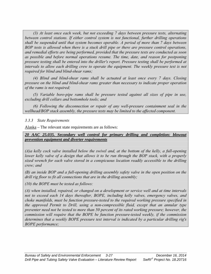
(3) At least once each week, but not exceeding 7 days between pressure tests, alternating between control stations. If either control system is not functional, further drilling operations shall be suspended until that system becomes operable. A period of more than 7 days between BOP tests is allowed when there is a stuck drill pipe or there are pressure control operations, and remedial efforts are being performed, provided that the pressure tests are conducted as soon as possible and before normal operations resume. The time, date, and reason for postponing pressure testing shall be entered into the driller's report. Pressure testing shall be performed at intervals to allow each drilling crew to operate the equipment. The weekly pressure test is not required for blind and blind-shear rams;
(4) Blind and blind-shear rams shall be actuated at least once every 7 days. Closing pressure on the blind and blind-shear rams greater than necessary to indicate proper operation of the rams is not required;
(5) Variable bore-pipe rams shall be pressure tested against all sizes of pipe in use, excluding drill collars and bottomhole tools; and
(6) Following the disconnection or repair of any well-pressure containment seal in the wellhead/BOP stack assembly, the pressure tests may be limited to the affected component.
3.3.3 State Requirements Alaska – The relevant state requirements are as follows:
20 AAC 25.035. Secondary well control for primary drilling and completion: blowout prevention equipment and diverter requirements (A)a kelly cock valve installed below the swivel and, at the bottom of the kelly, a full-opening lower kelly valve of a design that allows it to be run through the BOP stack, with a properly sized wrench for each valve stored in a conspicuous location readily accessible to the drilling crew; and (B) an inside BOP and a full-opening drilling assembly safety valve in the open position on the drill rig floor to fit all connections that are in the drilling assembly; (10) the BOPE must be tested as follows: (A) when installed, repaired, or changed on a development or service well and at time intervals not to exceed each 14 days thereafter, BOPE, including kelly valves, emergency valves, and choke manifolds, must be function pressure-tested to the required working pressure specified in the approved Permit to Drill, using a non-compressible fluid, except that an annular type preventer need not be tested to more than 50 percent of its rated working pressure; however, the commission will require that the BOPE be function pressure-tested weekly, if the commission determines that a weekly BOPE pressure test interval is indicated by a particular drilling rig's BOPE performance;
Bureau of Safety and Environmental Enforcement 3-27 December 16, 2014 Drill Pipe and Tubing Safety Valve Evaluation – Literature Review Report SwRI Project No. 18.20716
(B) when installed, repaired, or changed on an exploratory or stratigraphic test well and at least once a week thereafter, BOPE, including kelly valves, emergency valves, and choke manifolds, must be function pressure-tested to the required working pressure specified in the approved Permit to Drill, using a non-compressible fluid, except that an annular type preventer need not be tested to more than 50 percent of its rated working pressure; (9) for rotary drilling rig operations, auxiliary well control equipment must include (A) a kelly cock valve installed below the swivel and, at the bottom of the kelly, a full-opening lower kelly valve of a design that allows it to be run through the BOP stack, with a properly sized wrench for each valve stored in a conspicuous location readily accessible to the drilling crew; and (B) an inside BOP and a full-opening drilling assembly safety valve in the open position on the drill rig floor to fit all connections that are in the drilling assembly; (10) the BOPE must be tested as follows: (A) when installed, repaired, or changed on a development or service well and at time intervals not to exceed each 14 days thereafter, BOPE, including kelly valves, emergency valves, and choke manifolds, must be function pressure-tested to the required working pressure specified in the approved Permit to Drill, using a non-compressible fluid, except that an annular type preventer need not be tested to more than 50 percent of its rated working pressure; however, the commission will require that the BOPE be function pressure-tested weekly, if the commission determines that a weekly BOPE pressure test interval is indicated by a particular drilling rig's BOPE performance; (B) when installed, repaired, or changed on an exploratory or stratigraphic test well and at least once a week thereafter, BOPE, including kelly valves, emergency valves, and choke manifolds, must be function pressure-tested to the required working pressure specified in the approved Permit to Drill, using a non-compressible fluid, except that an annular type preventer need not be tested to more than 50 percent of its rated working pressure;
Texas – The relevant state requirements are as follows:
(iv) Operators shall install a drill pipe safety valve to prevent backflow of water, oil, gas, or other formation fluids into the drill string. …[Clauses not pertaining directly to subject removed for brevity.] (vi) When using a Kelly rig during drilling, the well shall be fitted with an upper Kelly cock in proper working order to close in the drill string below hose and swivel, when necessary for well control. A lower Kelly safety valve shall be installed so that it can be run through the blowout preventer. When needed for well control, the operator shall maintain at all times on the rig floor safety valves to include: [Clauses not pertaining directly to subject removed for brevity.]
(II) full-opening safety valve; and (III) inside blowout preventer valve with wrenches, handling tools, and necessary subs for all drilling pipe sizes in use.
Bureau of Safety and Environmental Enforcement 3-28 December 16, 2014 Drill Pipe and Tubing Safety Valve Evaluation – Literature Review Report SwRI Project No. 18.20716
(vii) Control equipment shall be certified in accordance with API Standard 53 as operable under the product manufacturer’s minimum operational specifications. Certification shall include the proper operation of the closing unit valving, the pressure gauges, and the manufacturer’s recommended accumulator fluids. Certification shall be obtained through an independent company that tests blowout preventers, stacks and casings. Certification shall be performed every five (5) years and the proof of certification shall be made available upon request of the Commission. (viii) All well control equipment shall be in good working condition at all times. All outlets, fittings, and connections on the casing, blowout preventers, choke manifold, and auxiliary wellhead equipment that may be subjected to wellhead pressure shall be of a material and construction to withstand or exceed the anticipated pressure. The lines from outlets on or below the blowout preventers shall be securely installed, anchored, and protected from damage. (ix) In addition to the primary closing system, including an accumulator system, the blowout preventers shall have a secondary location for closure. (x) Testing of blowout prevention equipment. (I) Ram type blowout prevention equipment shall be tested to at least the maximum anticipated surface pressure of the well, but not less than 1,500 psi, before drilling the plug on the surface casing. (II) Blowout prevention equipment shall be tested upon installation, after the disconnection or repair of any pressure containment seal in the blowout preventer stack, choke line, or choke manifold, limited to the affected component, with testing to occur at least every 21 days. When requested, the district director shall be notified before the commencement of a test.
Wyoming – The relevant state requirements are as follows for all BOPs:
• Additional BOP equipment shall include one upper kelly cock, and one drill pipe safety valve with subs to fit all drill string connections in use.
• The choke and kill line valves, choke manifold valves, upper and lower kelly cocks, drill pipe safety valves and inside BOP shall be tested with pressure applied from the wellbore side. All valves, including check valves, located downstream of the valve being pressure tested, will be in the open position.
3.3.4 International Requirements There were no identified prescriptive requirements by international regulators for this
equipment.
Bureau of Safety and Environmental Enforcement 3-29 December 16, 2014 Drill Pipe and Tubing Safety Valve Evaluation – Literature Review Report SwRI Project No. 18.20716

3.3.5 Standards Overview API-7-1
This standard does not provide detailed verification requirements. The design performance for surface and downhole kelly valves are:
• Body and any steam seal shall hold internal pressure equal to the shell test pressure • Stem seal shall hold external pressure at a low pressure of 1.7 MPa and at a minimum
high pressure of 13.8 MPa. • Closure seat shall hold pressure from below at a low pressure of 1.7 MPa and at a high
pressure equal to the maximum rated working pressure. • Closure seal shall hold pressure from above at a low pressure of 1.7 MPa and at a high
pressure equal to the maximum rated working pressure. • Sealing temperature range verified by testing. • Designed to be capable of: ○ Repeated operation in drilling mud ○ Closing to shut off a mud flow from the drill string ○ Sealing over the design range of temperature and tension load conditions
The testing is performed through hydrostatic and shell testing up to the working pressure of the valve.
The standard points out the following factors related to gas-tight sealing:
• Kelly valves and other types of drill-stem safety valves have not historically been designed with gas-tight sealing mechanisms. Valves that are designed to operate under these conditions are known as gas-tight valves. See 5.7.3 for optional performance verification testing that may be requested as a supplemental requirement by purchaser to verify gas-tight sealing design and for routine acceptance testing for each gastight valve supplied.
• Supplemental performance verification testing of drill-stem safety valves designed and manufactured in accordance with this part of ISO 1 0424 shall be carried out and/or certified by a quality organization independent of the design function. Since leak-testing at high pressure is potentially more hazardous with gas than with fluids of low compressibility, gas testing at high pressure shall be restricted to performance verification testing. Nitrogen or other suitable non-flammable gas should be used at ambient-temperature conditions. Otherwise, testing at low and high pressures shall be conducted in accordance with 5.4.3. No gas bubbles shall be observed in a 5 min test period. For each valve manufactured to the same specifications as a valve that has been designed and verified as being capable of gas-tight sealing, a gas test at low pressure to 0,62 MPa (90 psi), using ambient-temperature air, shall be performed in accordance with appropriate subclauses in 5.4.3. No gas bubbles shall be observed in a 5 min test period.
Bureau of Safety and Environmental Enforcement 3-30 December 16, 2014 Drill Pipe and Tubing Safety Valve Evaluation – Literature Review Report SwRI Project No. 18.20716
API 53
This standard does not provide detailed guidance on the design of any components. There are field-testing requirements in this document.
• There should be a low- and high-pressure testing of the valves when the BOP is installed. The low-pressure tests are in the range of 250 psi to 350 psi and the high-pressure test is at the rated working pressure of the valve.
• Subsequent tests of the valve are identical to the initial testing, except that the maximum test condition is the maximum shut-in pressure of the well. For subsea testing, the maximum pressure is the same as that used for the ram preventer.
3.4 Drill String Safety Valve
3.4.1 Overall Equipment Summary This section discusses the high-level requirements noted in Section 3.1 across all
regulations and standards studied for this product. The subsequent sections provide the detailed content for federal, state, and international regulations, as well as equipment standards.
Required for Installation
• BSEE requires that BOPs have kelly valves, but specific requirements for kelly valves are largely a peripheral element, as opposed to the many requirements for the actual BOP. The same approach is used by the states of Alaska and Texas.
• BSEE requires that a drill string safety valve for the casing string size being run must be on the rig floor and in the open position. Any tooling (e.g, wrenches) needed for actuation must be available.
Verification Requirements
• API 7-1 does not provide prescriptive verification requirements, though it does inform on the test pressures that the valves should be designed to hold. The pressures range from a low-pressure evaluation at 1.7 MPa and a high pressure up to rated working pressure.
Validation Requirements
• API 7-1 notes that safety valves are not designed to be “bubble tight” when used in gas applications. Some additional validation testing is outlined (see Section 3.3.5) when using the valves in gas service.
Field-Testing Requirements
• 30 CFR 250.445 requires that safety valves be tested when the BOP is installed and within two weeks of the last test. Testing is also required prior to drilling out each string of casing or liner. Testing should be at the pipe-ram test pressure.
• Alaska requires that the valves be tested every 14 days to the required working pressure stated on the permit. The testing shall be conducted with an incompressible fluid. This testing should be weekly on exploratory wells.
• Texas uses a 21-day interval for testing and Wyoming does not have a set time period.
Bureau of Safety and Environmental Enforcement 3-31 December 16, 2014 Drill Pipe and Tubing Safety Valve Evaluation – Literature Review Report SwRI Project No. 18.20716
• API 53 states that the valves should be tested after installation. The test pressure on the low end is in the range of 250 psi to 350 psi and the high-pressure test is at the rated working pressure of the valve. Subsequent tests should use the maximum shut-in pressure of the well and subsea tests should use the pressure from the ram test.
• Norsok D-010 requires safety valves be tested to the maximum section design pressure every 14 days and to working pressure every six months.
• Canada requires a test every 14 days. The test should consist of a low-pressure test at 1,400 kPa to 2,000 kPa, and then a high-pressure test.
3.4.2 Federal Requirements The requirements for drill string safety valves can be found in 30 CFR 250. It should be
noted that no relevant material for this product was found in any recent notices to lessees or safety alerts published on the BSEE webpage. The relevant sections from the CFR are:
§250.445 What are the requirements for kelly valves, inside BOPs, and drill-string safety valves?
You must use or provide the following BOP equipment during drilling operations: [Clauses not pertaining directly to subject removed for brevity.]
(f) A drill-string safety valve in the open position located on the rig floor. You must have a drill-string safety valve available for each size connection in the drill string;
(g) When running casing, you must have a safety valve in the open position available on the rig floor to fit the casing string being run in the hole;
(h) All required manual and remote-controlled kelly valves, drill-string safety valves, and comparable-type valves (i.e., kelly-type valve in a top-drive system) must be essentially full-opening; and
(i) The drilling crew must have ready access to a wrench to fit each manual valve.
§250.447 When must I pressure test the BOP system? You must pressure test your BOP system (this includes the choke manifold, kelly valves,
inside BOP, and drill-string safety valve): (a) When installed; (b) Before 14 days have elapsed since your last BOP pressure test. You must begin to test
your BOP system before midnight on the 14th day following the conclusion of the previous test. However, the District Manager may require more frequent testing if conditions or BOP performance warrant; and
(c) Before drilling out each string of casing or a liner. The District Manager may allow you to omit this test if you didn't remove the BOP stack to run the casing string or liner and the required BOP test pressures for the next section of the hole are not greater than the test pressures for the previous BOP test. You must indicate in your APD which casing strings and liners meet these criteria.
Bureau of Safety and Environmental Enforcement 3-32 December 16, 2014 Drill Pipe and Tubing Safety Valve Evaluation – Literature Review Report SwRI Project No. 18.20716
§250.1610 Blowout preventer systems and system components. [Clauses not pertaining directly to subject removed for brevity.]
(d) BOP equipment. All BOP systems shall be equipped and provided with the following: [Clauses not pertaining directly to subject removed for brevity.]
(10) The following system components: [Clauses not pertaining directly to subject removed for brevity.]
(ii) An inside BOP and an essentially full-opening, drill-string safety valve in the open position on the rig floor at all times while drilling operations are being conducted. These valves shall be maintained on the rig floor to fit all connections that are in the drill string. A wrench to fit the drill-string safety valve shall be stored in a location readily accessible to the drilling crew;
(iii) A safety valve available on the rig floor assembled with the proper connection to fit the casing string being run in the hole; and
§250.1611 Blowout preventer systems tests, actuations, inspections, and maintenance. [Clauses not pertaining directly to subject removed for brevity.]
(c) In conjunction with the weekly pressure test of BOP systems required in paragraph (d) of this section, the choke manifold valves, upper and lower kelly cocks, and drill-string safety valves shall be pressure tested to pipe-ram test pressures. Safety valves with proper casing connections shall be actuated prior to running casing.
(d) BOP system shall be pressure tested as follows: (1) When installed; (2) Before drilling out each string of casing or before continuing operations in cases where
cement is not drilled out; (3) At least once each week, but not exceeding 7 days between pressure tests, alternating
between control stations. If either control system is not functional, further drilling operations shall be suspended until that system becomes operable. A period of more than 7 days between BOP tests is allowed when there is a stuck drill pipe or there are pressure control operations and remedial efforts are being performed, provided that the pressure tests are conducted as soon as possible and before normal operations resume. The date, time, and reason for postponing pressure testing shall be entered into the driller's report. Pressure testing shall be performed at intervals to allow each drilling crew to operate the equipment. The weekly pressure test is not required for blind and blind-shear rams;
(4) Blind and blind-shear rams shall be actuated at least once every 7 days. Closing pressure on the blind and blind-shear rams greater than necessary to indicate proper operation of the rams is not required;
(5) Variable bore-pipe rams shall be pressure tested against all sizes of pipe in use, excluding drill collars and bottomhole tools; and
Bureau of Safety and Environmental Enforcement 3-33 December 16, 2014 Drill Pipe and Tubing Safety Valve Evaluation – Literature Review Report SwRI Project No. 18.20716
(6) Following the disconnection or repair of any well-pressure containment seal in the wellhead/BOP stack assembly. In this situation, the pressure tests may be limited to the affected component.
§250.1625 Blowout preventer system testing, records, and drills. [Clauses not pertaining directly to subject removed for brevity.]
(c) In conjunction with the weekly pressure test of BOP systems required in paragraph (d) of this section, the choke manifold valves, upper and lower kelly cocks, and drill-string safety valves shall be pressure tested to pipe-ram test pressures. Safety valves with proper casing connections shall be actuated prior to running casing.
(d) BOP system shall be pressure tested as follows: (1) When installed; (2) Before drilling out each string of casing or before continuing operations in cases where
cement is not drilled out; (3) At least once each week, but not exceeding 7 days between pressure tests, alternating
between control stations. If either control system is not functional, further drilling operations shall be suspended until that system becomes operable. A period of more than 7 days between BOP tests is allowed when there is a stuck drill pipe or there are pressure control operations, and remedial efforts are being performed, provided that the pressure tests are conducted as soon as possible and before normal operations resume. The time, date, and reason for postponing pressure testing shall be entered into the driller's report. Pressure testing shall be performed at intervals to allow each drilling crew to operate the equipment. The weekly pressure test is not required for blind and blind-shear rams;
(4) Blind and blind-shear rams shall be actuated at least once every 7 days. Closing pressure on the blind and blind-shear rams greater than necessary to indicate proper operation of the rams is not required;
(5) Variable bore-pipe rams shall be pressure tested against all sizes of pipe in use, excluding drill collars and bottomhole tools; and
(6) Following the disconnection or repair of any well-pressure containment seal in the wellhead/BOP stack assembly, the pressure tests may be limited to the affected component.
3.4.3 State Requirements Alaska – The relevant state requirements are as follows:
20 AAC 25.035. Secondary well control for primary drilling and completion: blowout prevention equipment and diverter requirements (B) an inside BOP and a full-opening drilling assembly safety valve in the open position on the drill rig floor to fit all connections that are in the drilling assembly;
Bureau of Safety and Environmental Enforcement 3-34 December 16, 2014 Drill Pipe and Tubing Safety Valve Evaluation – Literature Review Report SwRI Project No. 18.20716
Texas – The relevant statement requirements are as follows:
(iv) Operators shall install a drill pipe safety valve to prevent backflow of water, oil, gas, or other formation fluids into the drill string.
[Clauses not pertaining directly to subject removed for brevity.]
(vi) When using a Kelly rig during drilling, the well shall be fitted with an upper Kelly cock in proper working order to close in the drill string below hose and swivel, when necessary for well control. A lower Kelly safety valve shall be installed so that it can be run through the blowout preventer. When needed for well control, the operator shall maintain at all times on the rig floor safety valves to include: (I) full-opening safety valve; and (II) inside blowout preventer valve with wrenches, handling tools, and necessary subs for all drilling pipe sizes in use. (vii) Control equipment shall be certified in accordance with API Standard 53 as operable under the product manufacturer's minimum operational specifications. Certification shall include the proper operation of the closing unit valving, the pressure gauges, and the manufacturer's recommended accumulator fluids. Certification shall be obtained through an independent company that tests blowout preventers, stacks and casings. Certification shall be performed every five (5) years and the proof of certification shall be made available upon request of the Commission. (viii) All well control equipment shall be in good working condition at all times. All outlets, fittings, and connections on the casing, blowout preventers, choke manifold, and auxiliary wellhead equipment that may be subjected to wellhead pressure shall be of a material and construction to withstand or exceed the anticipated pressure. The lines from outlets on or below the blowout preventers shall be securely installed, anchored, and protected from damage. (ix) In addition to the primary closing system, including an accumulator system, the blowout preventers shall have a secondary location for closure. (x) Testing of blowout prevention equipment. (I) Ram type blowout prevention equipment shall be tested to at least the maximum anticipated surface pressure of the well, but not less than 1,500 psi, before drilling the plug on the surface casing. (II) Blowout prevention equipment shall be tested upon installation, after the disconnection or repair of any pressure containment seal in the blowout preventer stack, choke line, or choke manifold, limited to the affected component, with testing to occur at least every 21 days. When requested, the district director shall be notified before the commencement of a test.
Bureau of Safety and Environmental Enforcement 3-35 December 16, 2014 Drill Pipe and Tubing Safety Valve Evaluation – Literature Review Report SwRI Project No. 18.20716
Wyoming – The relevant statement requirements are as follows for all BOPs:
• Additional BOP equipment shall include one upper kelly cock, and one drill pipe safety valve with subs to fit all drill string connections in use.
• The choke and kill line valves, choke manifold valves, upper and lower kelly cocks, drill pipe safety valves and inside BOP shall be tested with pressure applied from the wellbore side. All valves, including check valves, located downstream of the valve being pressure tested, will be in the open position.
3.4.4 International Requirements There were no identified prescriptive requirements by international regulators for this
equipment.
3.4.5 Standards Overview API 53
This standard does not provide detailed guidance on the design of any components. There are field-testing requirements in this document.
• There should be a low- and high-pressure testing of the valves when the BOP is installed. The low-pressure tests are in the range of 250 psi to 350 psi and the high-pressure test is at the rated working pressure of the valve.
• Subsequent tests of the valve are identical to the initial testing, except that the maximum performed is the maximum shut-in pressure of the well. For subsea testing, the maximum pressure is the same as that used for the ram preventer.
3.5 Tubing Plugs
3.5.1 Overall Equipment Summary This section discusses the high-level requirements noted in Section 3.1 across all
regulations and standards studied for this product. The subsequent sections provide the detailed content for federal, state, and international regulations, as well as equipment standards.
Required for Installation
• BSEE requires that subsurface safety devices be installed in the tubing of installations open to hydrocarbon-bearing zones. While this requirement is typically filled by an SSSV, a tubing plug can be used in this instance. This requirement also applies to new completions (once well is perforated) and for wells shut in longer than six months.
• BSEE requires that a tubing plug be set at no more than 100 feet above the perforated interval when permanently plugging a well.
• California allows for a tubing plug to be used in lieu of SSSVs for shut-in wells that are capable of flow. If removed from a well, a replacement must be promptly installed.
Bureau of Safety and Environmental Enforcement 3-36 December 16, 2014 Drill Pipe and Tubing Safety Valve Evaluation – Literature Review Report SwRI Project No. 18.20716

Verification Requirements
The literature review did not reveal any pertinent verification requirements for this product.
Validation Requirements
The literature review did not reveal any pertinent validation requirements for this product.
Field-Testing Requirements
• BSEE requires that tubing plugs are tested for leakage every six months. The allowed leakage rates are 200 cc/min for liquid and 5 scfm for gas. If the plug fails the test, it must be removed, repaired, and reinstalled. Alternatively, an additional tubing plug can be used.
• California requires that tubing plugs be tested for holding pressure every six months. There appears to be some inconsistency in the California code. Section 1724 references testing at six-month intervals, while Section 1747 uses a period of one month. It is assumed that the latter is really intended as a first test within the first month of installation and not at regular intervals.
3.5.2 Federal Requirements The requirements for tubing plugs can be found in 30 CFR 250. It should be noted that
no relevant material for this product was found in any recent notices to lessees or safety alerts published on the BSEE webpage. The relevant sections from the CFR are:
§250.502 Equipment movement. The movement of well-completion rigs and related equipment on and off a platform or from
well to well on the same platform, including rigging up and rigging down, shall be conducted in a safe manner. All wells in the same well-bay which are capable of producing hydrocarbons shall be shut in below the surface with a pump-through-type tubing plug and at the surface with a closed master valve prior to moving well-completion rigs and related equipment, unless otherwise approved by the District Manager. A closed surface-controlled subsurface safety valve of the pump-through type may be used in lieu of the pump-through-type tubing plug, provided that the surface control has been locked out of operation. The well from which the rig or related equipment is to be moved shall also be equipped with a back-pressure valve prior to removing the blowout preventer (BOP) system and installing the tree.
Bureau of Safety and Environmental Enforcement 3-37 December 16, 2014 Drill Pipe and Tubing Safety Valve Evaluation – Literature Review Report SwRI Project No. 18.20716
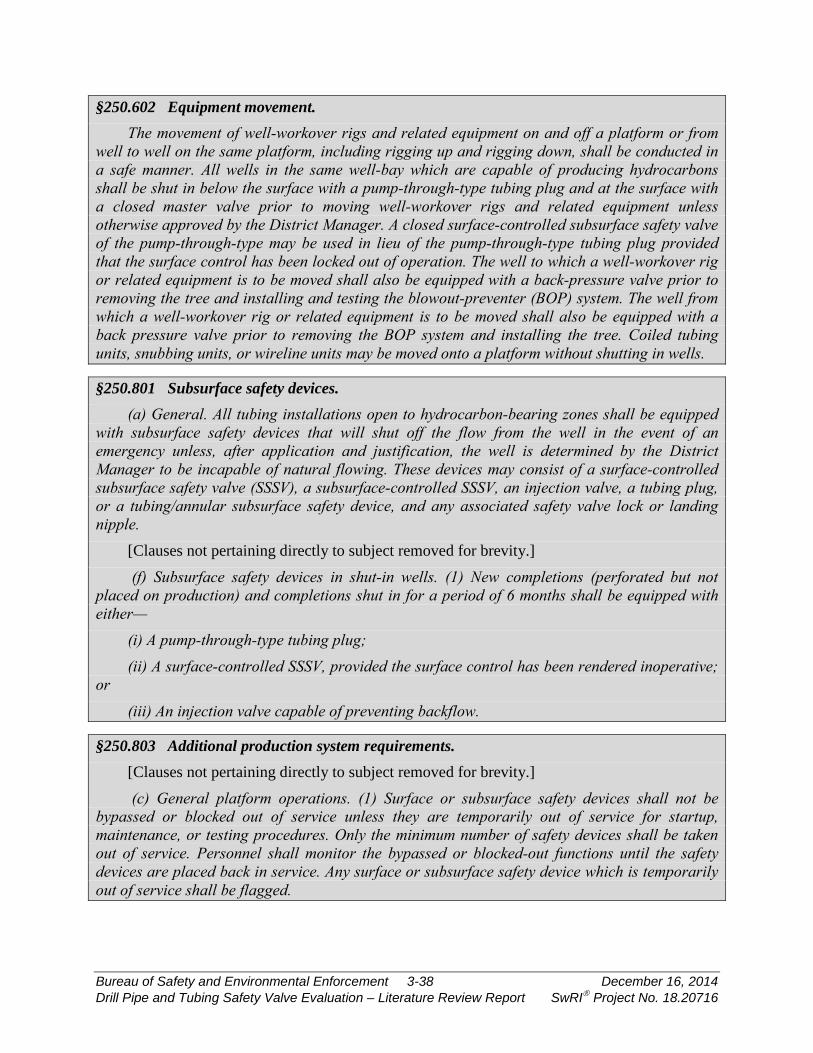
§250.602 Equipment movement. The movement of well-workover rigs and related equipment on and off a platform or from
well to well on the same platform, including rigging up and rigging down, shall be conducted in a safe manner. All wells in the same well-bay which are capable of producing hydrocarbons shall be shut in below the surface with a pump-through-type tubing plug and at the surface with a closed master valve prior to moving well-workover rigs and related equipment unless otherwise approved by the District Manager. A closed surface-controlled subsurface safety valve of the pump-through-type may be used in lieu of the pump-through-type tubing plug provided that the surface control has been locked out of operation. The well to which a well-workover rig or related equipment is to be moved shall also be equipped with a back-pressure valve prior to removing the tree and installing and testing the blowout-preventer (BOP) system. The well from which a well-workover rig or related equipment is to be moved shall also be equipped with a back pressure valve prior to removing the BOP system and installing the tree. Coiled tubing units, snubbing units, or wireline units may be moved onto a platform without shutting in wells.
§250.801 Subsurface safety devices. (a) General. All tubing installations open to hydrocarbon-bearing zones shall be equipped
with subsurface safety devices that will shut off the flow from the well in the event of an emergency unless, after application and justification, the well is determined by the District Manager to be incapable of natural flowing. These devices may consist of a surface-controlled subsurface safety valve (SSSV), a subsurface-controlled SSSV, an injection valve, a tubing plug, or a tubing/annular subsurface safety device, and any associated safety valve lock or landing nipple.
[Clauses not pertaining directly to subject removed for brevity.]
(f) Subsurface safety devices in shut-in wells. (1) New completions (perforated but not placed on production) and completions shut in for a period of 6 months shall be equipped with either—
(i) A pump-through-type tubing plug; (ii) A surface-controlled SSSV, provided the surface control has been rendered inoperative;
or
(iii) An injection valve capable of preventing backflow.
§250.803 Additional production system requirements. [Clauses not pertaining directly to subject removed for brevity.]
(c) General platform operations. (1) Surface or subsurface safety devices shall not be bypassed or blocked out of service unless they are temporarily out of service for startup, maintenance, or testing procedures. Only the minimum number of safety devices shall be taken out of service. Personnel shall monitor the bypassed or blocked-out functions until the safety devices are placed back in service. Any surface or subsurface safety device which is temporarily out of service shall be flagged.
Bureau of Safety and Environmental Enforcement 3-38 December 16, 2014 Drill Pipe and Tubing Safety Valve Evaluation – Literature Review Report SwRI Project No. 18.20716

(2) When wells are disconnected from producing facilities and blind flanged, equipped with a tubing plug, or the master valves have been locked closed, you are not required to comply with the provisions of API RP 14C (as incorporated by reference in §250.198) or this regulation concerning the following:
(i) Automatic fail-close SSV's on wellhead assemblies, and (ii) The PSH and PSL shut-in sensors in flowlines from wells. (3) When pressure or atmospheric vessels are isolated from production facilities (e.g., inlet
valve locked closed or inlet blind-flanged) and are to remain isolated for an extended period of time, safety device compliance with API RP 14C or this subpart is not required.
(4) All open-ended lines connected to producing facilities and wells shall be plugged or blind-flanged, except those lines designed to be open-ended such as flare or vent lines.
(d) Welding and burning practices and procedures. All welding, burning, and hot-tapping activities shall be conducted according to the specific requirements in §§250.109 through 250.113 of this part.
§250.804 Production safety-system testing and records. (a) Inspection and testing. The safety-system devices shall be successfully inspected and
tested by the lessee at the interval specified below or more frequently if operating conditions warrant. Testing must be in accordance with API RP 14C, Appendix D (as incorporated by reference in §250.198), and the following:
(1) Testing requirements for subsurface safety devices are as follows: [Clauses not pertaining directly to subject removed for brevity.]
(iii) Each tubing plug installed in a well shall be inspected for leakage by opening the well to possible flow at intervals not exceeding 6 months. If a liquid leakage rate in excess of 200 cubic centimeters per minute or a gas leakage rate in excess of 5 cubic feet per minute is observed, the device shall be removed, repaired and reinstalled, or replaced. An additional tubing plug may be installed in lieu of removal.
(iv) Injection valves shall be tested in the manner as outlined for testing tubing plugs in paragraph (a)(1)(iii) of this section. Leakage rates outlined in paragraph (a)(1)(iii) of this section shall apply.
§250.1715 How must I permanently plug a well? (a) You must permanently plug wells according to the table in this section. The District
Manager may require additional well plugs as necessary.
Bureau of Safety and Environmental Enforcement 3-39 December 16, 2014 Drill Pipe and Tubing Safety Valve Evaluation – Literature Review Report SwRI Project No. 18.20716
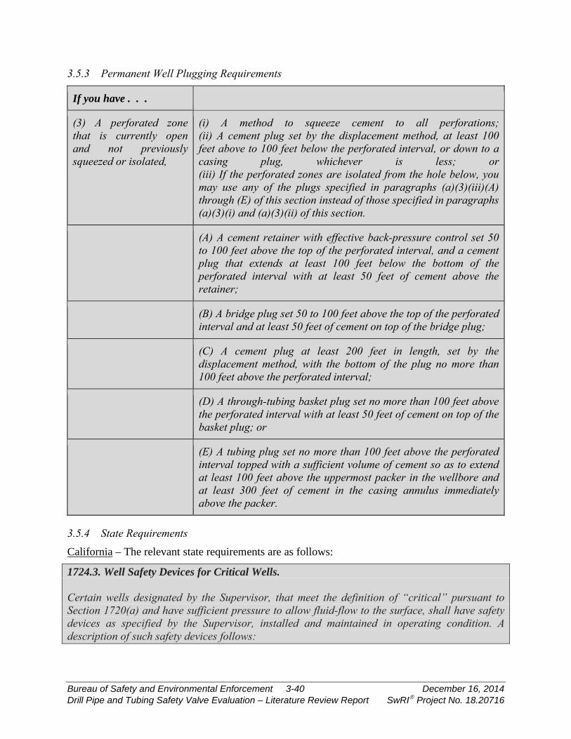
3.5.3 Permanent Well Plugging Requirements
If you have . . . Then you must use . . .
(3) A perforated zone that is currently open and not previously squeezed or isolated,
(i) A method to squeeze cement to all perforations; (ii) A cement plug set by the displacement method, at least 100 feet above to 100 feet below the perforated interval, or down to a casing plug, whichever is less; or (iii) If the perforated zones are isolated from the hole below, you may use any of the plugs specified in paragraphs (a)(3)(iii)(A) through (E) of this section instead of those specified in paragraphs (a)(3)(i) and (a)(3)(ii) of this section.
(A) A cement retainer with effective back-pressure control set 50 to 100 feet above the top of the perforated interval, and a cement plug that extends at least 100 feet below the bottom of the perforated interval with at least 50 feet of cement above the retainer;
(B) A bridge plug set 50 to 100 feet above the top of the perforated interval and at least 50 feet of cement on top of the bridge plug;
(C) A cement plug at least 200 feet in length, set by the displacement method, with the bottom of the plug no more than 100 feet above the perforated interval;
(D) A through-tubing basket plug set no more than 100 feet above the perforated interval with at least 50 feet of cement on top of the basket plug; or
(E) A tubing plug set no more than 100 feet above the perforated interval topped with a sufficient volume of cement so as to extend at least 100 feet above the uppermost packer in the wellbore and at least 300 feet of cement in the casing annulus immediately above the packer.
3.5.4 State Requirements California – The relevant state requirements are as follows:
1724.3. Well Safety Devices for Critical Wells. Certain wells designated by the Supervisor, that meet the definition of “critical” pursuant to Section 1720(a) and have sufficient pressure to allow fluid-flow to the surface, shall have safety devices as specified by the Supervisor, installed and maintained in operating condition. A description of such safety devices follows:
Bureau of Safety and Environmental Enforcement 3-40 December 16, 2014 Drill Pipe and Tubing Safety Valve Evaluation – Literature Review Report SwRI Project No. 18.20716

(a) Surface safety devices. (1) Fail-close, well shut-in or shut-down devices. Wellhead assemblies shall be equipped with an automatic fail-close valve. For shut-in wells capable of flowing, a tubing plug may be installed in lieu of a subsurface tubing safety valve. Subsurface safety devices shall be installed, adjusted, and maintained to ensure reliable operation. If for any reason a subsurface safety device is removed from a well, a replacement subsurface safety device or tubing plug shall be promptly installed. Any well in which a subsurface safety device or tubing plug is installed shall have the tubing-casing annulus sealed at or below the valve- or plug-setting depth. A bypass-type packer that will seal the annulus on manual or automatic operation of the tubing subsurface safety device will meet this requirement.
1724.4. Testing and Inspection of Safety Devices. (a) All installed well safety devices, required pursuant to Section 1724.3 of this article, shall be tested at least every six (6) months, as follows: (1) Flow line pressure sensors shall be tested for proper pressure settings. (2) Automatic wellhead safety valves shall be tested for reliable operation and holding pressure. (3) Subsurface safety devices shall be tested for reliable operation. (4) Tubing plugs or packers shall be tested for holding pressure. (b) The appropriate Division district office shall be notified before such tests are made, as these tests may be witnessed by a Division inspector. Test failures not immediately repaired or corrected and not witnessed by a Division inspector shall be reported to the Division within 24 hours. (c) The Supervisor may establish a special testing schedule for safety devices other than that specified in this section, based upon equipment performance or special conditions. (d) The operator shall maintain records, available to Division personnel during business hours, showing the present status and history of each well safety device installed, including dates, details and results of inspections, tests, repairs, reinstallations, and replacements.
1747. Safety and Pollution Control. Operators shall equip wells and associated facilities with necessary safety devices and establish procedures as follows: (a) Subsurface safety device. All wells capable of flowing oil or gas to the ocean floor shall be equipped with a surface controlled subsurface tubing safety valve installed at a depth of 100 feet or more below the ocean floor. Such device shall be installed in all oil and gas wells, including artificial lift wells, unless proofs provided to the Supervisor that such wells are incapable of any natural flow to the ocean floor. For shut-in wells capable of flowing oil or gas, a tubing plug may be installed, in lieu of a subsurface safety device, and such plug shall also be installed when required by the Supervisor. (b) Subsurface safety devices shall be adjusted, installed, and maintained to insure reliable operation. When a subsurface safety device is removed from a well for repair or replacement, a standby subsurface safety device or tubing plug shall be available at the well location, and shall be immediately installed within the limits of practicability, consideration being given to time, equipment, and personnel safety. All wells in which subsurface safety device or tubing plug is installed shall have the tubing-casing annulus sealed below the valve or plug setting depth.
Bureau of Safety and Environmental Enforcement 3-41 December 16, 2014 Drill Pipe and Tubing Safety Valve Evaluation – Literature Review Report SwRI Project No. 18.20716
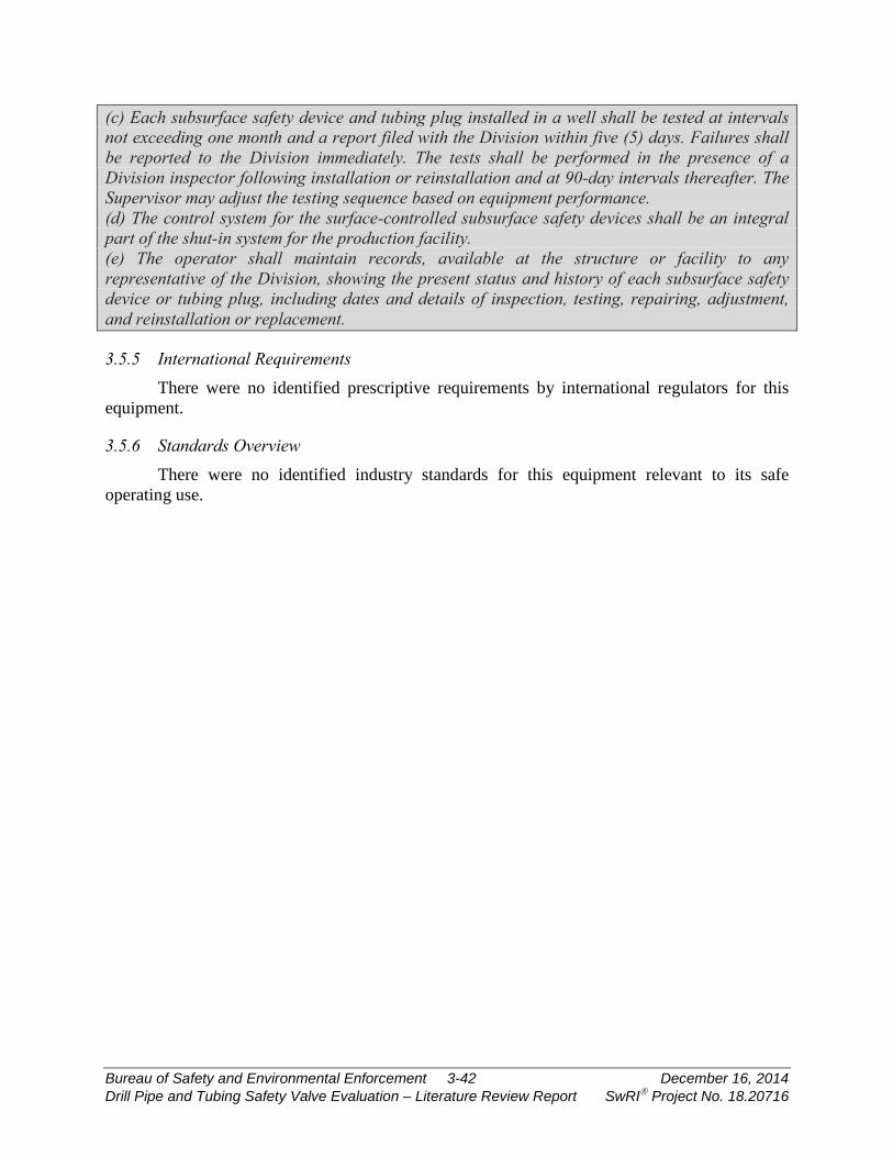
(c) Each subsurface safety device and tubing plug installed in a well shall be tested at intervals not exceeding one month and a report filed with the Division within five (5) days. Failures shall be reported to the Division immediately. The tests shall be performed in the presence of a Division inspector following installation or reinstallation and at 90-day intervals thereafter. The Supervisor may adjust the testing sequence based on equipment performance. (d) The control system for the surface-controlled subsurface safety devices shall be an integral part of the shut-in system for the production facility. (e) The operator shall maintain records, available at the structure or facility to any representative of the Division, showing the present status and history of each subsurface safety device or tubing plug, including dates and details of inspection, testing, repairing, adjustment, and reinstallation or replacement.
3.5.5 International Requirements There were no identified prescriptive requirements by international regulators for this
equipment.
3.5.6 Standards Overview There were no identified industry standards for this equipment relevant to its safe
operating use.
Bureau of Safety and Environmental Enforcement 3-42 December 16, 2014 Drill Pipe and Tubing Safety Valve Evaluation – Literature Review Report SwRI Project No. 18.20716

4. SUMMARY
This report provides a summary of the literature review conducted as part of the overall project. While some contrast in requirements was provided in this report, a subsequent gap analysis will be used to capture the variance in requirements across various jurisdictions. Some high-level conclusions from this literature review are:
• The U.S. is the sole national jurisdiction that has prescriptive requirements for safety-related equipment. Other global bodies lean on risk-based or performance-based systems in which guidelines are provided, but not prescriptive requirements. It should be noted that it is unclear how often operators deviate from accepted standards when making applications for safety cases. It is possible that an unwritten expectation of compliance exists and that the guidelines essentially result in more direct requirements. In that case, the most-thorough set of international regulations would be with the Norwegian PSA, particularly in regards to SSSVs.
• SSSVs are given far more attention with respect to verification, validation, and field testing requirements in regulations compared to the other products studied in this project. A key reason for this observation is that most tubing-retrievable SSSVs are essentially permanently-installed equipment, where the other three products are not.
• API 14A is leaned on as the recognized standard for SSSVs. The current revision of this standard (11th edition) does not contain prescriptive requirements for verification. The CFR has incorporated additional verification requirements for SSSVs used in HPHT applications. The upcoming release of the 12th edition of API 14A will roll these requirements into the specification, perhaps obsoleting the need for that section of the CFR.
• Most regulations point to API 14B for establishing leak rate criteria for SSSVs. These rates are 400 cm3/min for liquid and 15 scfm for gas. The leakage rates for U.S. waters are more stringent, as the allowed rates are 200 cm3/min and 5 scfm per 30 CFR 250.804.
Bureau of Safety and Environmental Enforcement 4-1 December 16, 2014 Drill Pipe and Tubing Safety Valve Evaluation – Literature Review Report SwRI Project No. 18.20716
5. REFERENCES
Alaska Administrative Code, Title 20, Chapter 25, November 2013.
API Recommended Practice 14B, 5th Edition, “Design, Installation, Operation, and Redress of Subsurface Safety Valve Equipment,” 2005.
API Recommended Practice 53, “Recommended Practices for Blowout Prevention Equipment Systems for Drilling Wells,” 2004.
API Specification 7-1, 1st Edition, “Specification for Rotary Drill Stem Elements,” 2012.
API Specification 14A, 11th Edition, “Specification for Subsurface Safety Valve Equipment,” 2005.
API Q1, 9th Edition, “Specification of Quality Management System Requirement for Manufacturing Organizations for the Petroleum and Natural Gas Industry,” June 2014.
Bourgoyne, Adam T., “Study of Drill String Valves,” Louisiana State University Report, September 2002.
Canada-Newfoundland and Labrador Offshore Petroleum Board and Canada-Nova Scotia Offshore Petroleum Board, “Drilling and Production Guidelines,” March 2011.
California Code of Regulations, Title 14, Division 2, Publication No. PRC04, January 2011.
Hauge, S. et al., “Barriers to prevent and limit acute releases to the sea,” Report from SINTEF, October 2011.
International Association of Oil and Gas Producers, “Regulators’ use of standards,” March 2010.
Netherlands Mining Regulations, December 2011.
NORSOK Standard D-010, “Well integrity in drilling and well operations,” Revision 4, June 2013.
Norway Petroleum Safety Authority, “Regulations Relating to Conducting Petroleum Activities,” December 2013.
Norway Petroleum Safety Authority, “Regulations Relating to Design and Outfitting of Facilities, etc. in the Petroleum Activities,” December 2013.
Norway Petroleum Safety Authority, “Regulations Relating to Health, Safety and the Environment in the Petroleum Activities and at Certain Onshore Facilities,” December 2013.
Pennsylvania Environmental Protection Code, Title 25, Chapter 78, September 2014.
Tennessee Statute 0400-53-02.04.
Texas Administrative Code, Title 16, Part 1, Chapter 3, March 2014.
TNO Paper Summary, “Exemption of SC-SSSV in Mature Onshore Gas Wells,” July 2014.
United Kingdom Health and Safety Executive, “A guide to the well aspects of the Offshore Installations and Wells (Design and Construction, etc.) Regulations,” 1996.
Bureau of Safety and Environmental Enforcement 5-1 December 16, 2014 Drill Pipe and Tubing Safety Valve Evaluation – Literature Review Report SwRI Project No. 18.20716
United Kingdom Health and Safety Executive, “High pressure, high temperature developments in the United Kingdom Continental Shelf,” 2005.
United States Code of Federal Regulations (CFR), Title 30, December 2014.
Wyoming Oil and Gas Commission Code, Chapter 3, Section 23.
Bureau of Safety and Environmental Enforcement 5-2 December 16, 2014 Drill Pipe and Tubing Safety Valve Evaluation – Literature Review Report SwRI Project No. 18.20716

Bureau of Safety and Environmental Enforcement B-1 September 15, 2015 Drill Pipe and Tubing Safety Valve Evaluation – Final Report SwRI Project No. 18.20716
APPENDIX B
Gap Analysis Report

Drill Pipe and Tubing Safety Valve Evaluation
GAP ANALYSIS REPORT - REVISED
SwRI® Project No. 18.20716 BSEE Contract E14PC00024
Prepared for:
Bureau of Safety and Environmental Enforcement 381 Elden Street, HE 3314 Herndon, Virginia 20170
April 22, 2015
S O U T H W E S T R E S E A R C H I N S T I T U T E®

Drill Pipe and Tubing Safety Valve Evaluation
GAP ANALYIS REPORT - REVISED
SwRI® Project No. 18.20716 BSEE Contract E14PC00024
Prepared for:
Bureau of Safety and Environmental Enforcement 381 Elden Street, HE 3314 Herndon, Virginia 20170
Prepared by:
Shane Siebenaler
Approved:
_____________________________________ Edgar B. Bowles, Jr., Director Fluids and Machinery Engineering Department
ADVERTISING, CONFIDENTIALITY, AND RECORD RETENTION POLICY
All work related to this project is subject to the Southwest Research Institute® Advertising, Confidentiality, and Record Retention Policy. This policy specifically addresses the distribution of abridged versions of SwRI® reports (including excerpts) and also restricts the use of the SwRI name, logo, and test results for advertising purposes. SwRI policies specifically prohibit the use in advertising of its name, logo, and results provided by our studies. The following paragraph, extracted verbatim from SwRI contractual documents clarifies this point:
“SwRI shall not publish or make known to others the subject matter or results of the Project or any information obtained in connection therewith which is proprietary and confidential to Client without Client’s written approval. No advertising or publicity containing any reference to SwRI, or any of their employees, either directly or by implication shall be made use of by Client or on Client’s behalf without SwRI’s written approval. In the event Client distributes any report issued by SwRI on this Project outside its own organization, such report shall be used in its entirety, unless SwRI approves a summary of abridgment for distribution.” SwRI will retain a record copy of the report for a period of five (5) years. This permits us
to answer questions that may be raised after a report has been mailed and provides a basis for additional work, if required. The contents of the report and any information that comes into our possession during the course of a study are held confidential to the company conducting the study and are not disclosed to anyone without client’s prior permission.
TABLE OF CONTENTS Section Page
TABLE OF CONTENTS ............................................................................................................ iii
NOMENCLATURE .................................................................................................................... iv
EXECUTIVE SUMMARY ........................................................................................................... v
1. INTRODUCTION ....................................................................................................... 1-1
1.1 Background ......................................................................................................... 1-1
1.2 Key Documents ................................................................................................... 1-1
1.3 Use of Standards ................................................................................................. 1-2
1.3.1 U.S. Regulations .......................................................................................... 1-2 1.3.2 Norwegian Regulations ................................................................................ 1-3
1.4 Gap Analysis Scope ............................................................................................ 1-5
2. GAP ANALYSIS ......................................................................................................... 2-1
3. CONCLUSIONS ......................................................................................................... 3-1
3.1 Summary ............................................................................................................. 3-1
3.2 Path Forward ....................................................................................................... 3-2
4. REFERENCES .......................................................................................................... 4-1
Bureau of Safety and Environmental Enforcement iii April 22, 2015 Drill Pipe and Tubing Safety Valve Evaluation – Gap Analysis Report SwRI Project No. 18.20716
NOMENCLATURE API American Petroleum Institute
ASME American Society of Mechanical Engineers
BSEE Bureau of Safety and Environmental Enforcement
cfm Cubic Feet Per Minute
CFR Code of Federal Regulations
ESD Emergency Shutdown Device
HPHT High Pressure High Temperature
MMS Minerals Management Service
NTL Notice to Lessees
OCS Outer Continental Shelf
OEM Original Equipment Manufacturer
PSA Petroleum Safety Authority
scfm Standard Cubic Feet Per Minute
SCSSV Surface-Controlled Subsurface Safety Valve
SPPE Safety and Pollution Prevention Equipment
SSCSV Subsurface-Controlled Subsurface Safety Valve
SSISV Subsurface Injection Safety Valve
SSV Surface Safety Valve
SSSVs Subsurface Safety Valves
TRSVs Tubing-Retrievable Safety Valves
Bureau of Safety and Environmental Enforcement iv April 22, 2015 Drill Pipe and Tubing Safety Valve Evaluation – Gap Analysis Report SwRI Project No. 18.20716
EXECUTIVE SUMMARY A gap analysis was conducted to determine differences in the Code of Federal
Regulations (CFR), Norwegian regulations, and various industries standards for the operation of subsurface safety valves (SSSVs). Some key gaps identified were:
• The CFR cites many requirements specific to versions of API standards that are no longer the active. The current standards versions cited are API 14A (11th Edition), API 14B (5th Edition), and API Q1 (8th Edition). These documents have been heavily revised (note: the 6th Edition of API 14B has been approved, but not yet published), so equipment suppliers and end users have two different sets of requirements: industry requirements to use the latest version of these standards and regulations that refer to prior versions of the same standards. 30 CFR 250.198 does provide allowances for using updated versions of standards, as long as particular conditions are met.
• There are no clear requirements in the CFR for evaluating the performance of SSSVs installed in wells in which direct leakage measurement is not possible.
• The omission of HPHT requirements from API 14A (11th Edition) resulted in the inclusion of such requirements in 30 CFR 250.807. The 12th Edition of API 14A appears to have closed these gaps, perhaps rendering 250.807 unnecessary.
• Although ASME SPPE-1-1994 is cited in 30 CFR 250.806, it is not part of the quality management programs utilized by the industry.
• Norway requires more-frequent testing for SSSVs early in their service life than does the CFR. The CFR requires that SSSVs be tested every six months. In Norway, SSSVs must be tested monthly until three consecutive successful tests are achieved. At that point, the interval is quarterly until three consecutive successful tests at that interval are achieved. It is only at that point that a six-month interval is used.
• While there is general alignment of allowed leakage rates for SSSVs, the CFR has essentially created a more-stringent set of requirements for SSSVs in wells with dry trees. This narrower range of allowed leakage does not appear anywhere else. It should be noted that the units for this leak rate (cfm) do not align with other requirements in the CFR or industry standards for this equipment (use of scfm).
• There is inconsistency in the required closure time for an SSSV, depending on the control signal type, reason for closure, and type of wellhead. Further, there are no requirements within design and operating standards driving valve suppliers and users to ensure that SSSVs will be able to meet these requirements.
• There is some misalignment of competency requirements for personnel. Subpart O of the CFR does not provide requirements for competency. An indirect set of requirements does appear in Subpart S. Norway requires competency and also that well control operators receive independent certification.
• There is inconsistency in the records retention requirements in the CFR, industry standards, and Norwegian requirements. Further, the CFR gives a time period, but does not note “when the clock starts.”
Bureau of Safety and Environmental Enforcement v April 22, 2015 Drill Pipe and Tubing Safety Valve Evaluation – Gap Analysis Report SwRI Project No. 18.20716
• There does not appear to be a requirement to notify regulators of a failure. Further, there is not a clear definition of what would constitute an SSSV failure.
A future project task will evaluate whether or not actions are warranted to assist in the closure of any of these gaps.
Bureau of Safety and Environmental Enforcement vi April 22, 2015 Drill Pipe and Tubing Safety Valve Evaluation – Gap Analysis Report SwRI Project No. 18.20716
1. INTRODUCTION
1.1 Background The regulatory framework in place for the U.S. Outer Continental shelf (OCS) activities
relating to tubing-retrievable subsurface safety valves (SSSVs) and similar safety products has been largely reactive to industry standardization of such equipment. Requirements for validation and verification often are implicit in the referenced standards and not augmented by separate requirements in the regulations. However, as technology has evolved, and as offshore wells are drilled in high-pressure and high-temperature (HPHT) wells (i.e., wells operating at >15,000 psi and/or 350°F), there is some disconnect between industry standards and regulatory response. As a result, it is critical to identify gaps between current industry practices and regulations to improve safety in the OCS.
An example of the difference between regulations, industry standards, and current practices can be found in testing requirements for tubing-retrievable safety valves (TRSVs) installed in the OCS. The Code of Federal Regulations (CFR) and API 14B both reference leakage requirements that are direct measurements through the closure mechanism. However, subsea trees prevent direct measurement, resulting in many operators utilizing an indirect approach through pressure monitoring. Thus, both the CFR and industry standards have not “caught up to” current practices.
To initiate the effort in identifying and then closing gaps in regulations, a literature review was performed to capture global requirements for key pieces of safety equipment and to also incorporate a review of key industry standards. That review report was previously submitted to BSEE (Literature Review Report, BSEE Contract E14PC00024). This document provides a gap analysis that is an output from the initial literature review. A subsequent project task will be used to provide recommendations for closing some of these gaps.
1.2 Key Documents The literature review (summarized in Literature Review Report, BSEE Contract
E14PC00024) revealed that there was an absence of prescriptive requirements in other jurisdictions regarding the use of kelly valves, drill-string safety valves, and tubing plugs, which were other types of equipment studied in this project. Most international regulations appear to focus on permanently-installed equipment and not peripheral components such as these items. Thus, the focus of the gap analysis was on subsurface safety valves (SSSVs).
The CFR provides a combination of prescriptive requirements, as well as clauses requiring compliance to API 14A and API 14B (note: this report will use the terminology standard to refer to such documents, even though specification or recommended practice is used in some document titles). The specific editions of these documents are 11th and 5th, respectively. API 14A has been updated to the 12th Edition, though it is currently not referenced in the CFR. API 14B is currently being revised to the 6th Edition. Any content from the proposed 6th Edition is taken from the ballot of the document that has recently closed. This material is subject to further changes and such changes will be reflected in future versions of materials for this project.
Section 53 of Norway’s “Facilities” regulations has a guidance document that links to NORSOK D-010 (Revision 3). The Petroleum Safety Authority (PSA) does not provide prescriptive requirements, so while NORSOK D-010 is only the recommended set of
Bureau of Safety and Environmental Enforcement 1-1 April 22, 2015 Drill Pipe and Tubing Safety Valve Evaluation – Gap Analysis Report SwRI Project No. 18.20716

requirements, it will be viewed as the de facto set of Norwegian regulations. This standard has recently been revised to Revision 4, though that version is not reflected in Norway’s regulations.
1.3 Use of Standards Both the CFR and Norway’s “Framework” regulations provide some guidance on the
interaction of industry standards and the regulations. However, BSEE provides prescriptive requirements for adherence to the requirements of many standards, while Norway uses such standards as “best practices” and not forced compliance.
1.3.1 U.S. Regulations 30 CFR 250.198 states:
(a) The BSEE is incorporating by reference the documents listed in paragraphs (e) through (k) of this section. Paragraphs (e) through (k) identify the publishing organization of the documents, the address and phone number where you may obtain these documents, and the documents incorporated by reference. The Director of the Federal Register has approved the incorporations by reference according to 5 U.S.C. 552(a) and 1 CFR part 51.
(1) Incorporation by reference of a document is limited to the edition of the publication that is cited in this section. Future amendments or revisions of the document are not included. The BSEE will publish any changes to a document in the FEDERAL REGISTER and amend this section.
(2) The BSEE may make the rule amending the document effective without prior opportunity for public comment when BSEE determines:
(i) That the revisions to a document result in safety improvements or represent new industry standard technology and do not impose undue costs on the affected parties; and
(ii) The BSEE meets the requirements for making a rule immediately effective under 5 U.S.C. 553.
(3) The effect of incorporation by reference of a document into the regulations in this part is that the incorporated document is a requirement. When a section in this part incorporates all of a document, you are responsible for complying with the provisions of that entire document, except to the extent that the section which incorporates the document by reference provides otherwise. When a section in this part incorporates part of a document, you are responsible for complying with that part of the document as provided in that section.
(b) The BSEE incorporated each document or specific portion by reference in the sections noted. The entire document is incorporated by reference, unless the text of the corresponding sections in this part calls for compliance with specific portions of the listed documents. In each instance, the applicable document is the specific edition or specific edition and supplement or addendum cited in this section.
(c) Under §§250.141 and 250.142, you may comply with a later edition of a specific document incorporated by reference, provided:
(1) You show that complying with the later edition provides a degree of protection, safety, or performance equal to or better than would be achieved by compliance with the listed edition; and
Bureau of Safety and Environmental Enforcement 1-2 April 22, 2015 Drill Pipe and Tubing Safety Valve Evaluation – Gap Analysis Report SwRI Project No. 18.20716

(2) You obtain the prior written approval for alternative compliance from the authorized BSEE official.
1.3.2 Norwegian Regulations Section 24 of the Framework regulations states:
When the responsible party makes use of a standard recommended in the guidelines to a provision of the regulations, as a means of complying with the requirements of the regulations in the area of health, safety and the environment, the responsible party can normally assume that the regulatory requirements have been met.
When other solutions than those recommended in the guidelines to a provision of the regulations are used, the responsible party shall be able to document that the chosen solution fulfils the regulatory requirements. Combinations of parts of standards shall be avoided, unless the responsible party is able to document that an equivalent level for health, safety and the environment can be achieved.
Existing documentation, including maritime certificates issued by Norwegian or foreign flag state authorities, can be used as a basis to document compliance with requirements stipulated in or in pursuance of these regulations.
The subsequent guidance section provides this background:
In activities covered by these regulations and regulations stipulated in pursuance of them, usage or customs in the industry, requirements and specifications evident from other documents, such as industry standards, which are nationally and internationally recognised within a specific discipline, e.g. standards that have been prepared under the auspices of CEN, CENELEC, ISO and IEC, will be normative. The same applies to industry standards prepared under the auspices of NORSOK, API and others.
The authorities' recommended solutions are indicated in the guidelines for the individual sections in the supplementary regulations. The authorities recommend the use of various industry standards or other normative documents, possibly with supplementary addendums evident from the guidelines, as a means to fulfil the regulatory requirements. Reference is made to such normative documents with date of publication and publishing/revision number, e.g. NORSOK xx, revision xx (date) in the reference lists in the guidelines regarding the regulations. The recommended solution becomes a recognised norm through this reference in the guidelines for the regulations. In areas where industry standards are not published, or these are not found satisfactory, the authorities will, in some cases, describe solutions in the guidelines for the provisions that indicate ways to fulfil the regulatory requirements. Such recommendations have the same status as recommended industry standards, as mentioned. According to the first subsection, the responsible party can normally assume that the recommended solution fulfils the relevant regulatory requirement.
Use of recognised standards is voluntary to the extent that other technical solutions, methods or procedures can be chosen if the responsible party can document that regulatory requirements will be fulfilled, cf. second subsection. When using other solutions than those recommended in the guidelines for a regulatory provision, this entails that, in accordance with the second subsection, the responsible party shall be able to document that the chosen solution fulfils the regulatory requirements. It is presumed that the regulations and the guidelines are
Bureau of Safety and Environmental Enforcement 1-3 April 22, 2015 Drill Pipe and Tubing Safety Valve Evaluation – Gap Analysis Report SwRI Project No. 18.20716

viewed in context to achieve the best possible understanding of the desired level of achievement through the regulations. Standards recommended in the guidelines will be key in interpreting the individual Regulatory requirements and in determining the level of health, safety and working environment. Combinations of parts of standards should be avoided, insofar as the responsible party cannot document that a corresponding level of health, safety and working environment is achieved.
The terms "should" and "can" are used in the guidelines regarding the supplementary regulations when reference is made to recommended solutions for fulfilling the regulatory requirements. In this context, the following is meant by these terms:
"Should", means the authorities' recommended way of fulfilling the functional requirement. Alternative solutions with documented corresponding functionality and quality can be used without having to present this to the authorities.
"Can", means an alternative, equal way of fulfilling the regulatory requirements, e.g. where the guidelines recommend using maritime standards as an alternative to following a NORSOK standard.
When the industry or others publish standards, it is normally assumed that the standards will be used as a basis for new facilities and for the field the standard describes. Where the authorities recommend using such standards, it is thus not the intention to go beyond the assumptions provided for the standards, unless specifically mentioned.
In the event of major retrofits or modifications to existing facilities, the new standards should be used. If it is not appropriate to use new standards, this should be based on safety-related considerations. Safety-related reasons to not use new standards can e.g. be that the use of new standards for existing solutions is considered to result in a particular risk. Existing facilities are facilities for which the Plan for Development and Operations (PDO) is approved, or a special permission has been granted under a PIO, cf. Sections 4-2 and 4-3 of the Petroleum Act, respectively, or facilities that have been granted consent to carry out petroleum activities. For mobile facilities, it is presumed that a facility is new when a new consent is applied for, in the same manner as according to the safety regulations that were in force until these regulations entered into force.
As regards the importance of previously granted exemptions for the facility for which consent is being sought, reference is made to the Guidelines regarding Section 70, final paragraph and Section 26 of the supplementary Management Regulations.
The term shall is also used in the guidelines regarding the regulations. In this context, shall mean a direct rendering of a statutory or regulatory requirement.
In addition to standards as described in the first paragraph, rules prepared by classification institutions, regulations prepared by other public authorities that do not directly apply to the petroleum activities, but which are still relevant for the field, and regulatory requirements that are not directly applied to the petroleum activities, but which govern corresponding or adjacent areas, for example requirements stipulated by the Norwegian Maritime Authority, the Norwegian Labour Inspection Authority, etc., can also be referred to in the guidelines as normative.
Bureau of Safety and Environmental Enforcement 1-4 April 22, 2015 Drill Pipe and Tubing Safety Valve Evaluation – Gap Analysis Report SwRI Project No. 18.20716

1.4 Gap Analysis Scope The gap analysis focuses on the contrast between:
• 30 CFR 250, Subpart H
• API 14A, 11th Edition
• API 14A, 12th Edition
• API 14B, 5th Edition
• API 14B, 6th Edition
• NORSOK D-010, Revision 3
• NORSOK D-010, Revision 4
Bureau of Safety and Environmental Enforcement 1-5 April 22, 2015 Drill Pipe and Tubing Safety Valve Evaluation – Gap Analysis Report SwRI Project No. 18.20716
2. GAP ANALYSIS The gap analysis was performed by identifying differences in these key areas:
• Required technical standards • High-pressure and/or high-temperature applications • Quality assurance requirements • Testing requirements • Operations • Personnel and training • Allowed use of subsurface-controlled valves • Records • Repair and redress • Failure reporting The focus of this analysis was on the installation, operation, and testing of valves in the
field. Design considerations, while indirectly covered by incorporation of technical standards into regulatory clauses, were not part of the intended scope of this gap analysis.
The following set of tables provides details on gaps identified for each of the key areas discussed at the beginning of this section.
Topic Required Technical Standards
Code of Federal Regulations
30 CFR 250.198 lists documents that are incorporated by reference. This section of the CFR references technical standards by specific editions or revisions (i.e., dated copies). Key documents relevant to this gap analysis are API 14A (11th Edition), API 14B (5th Edition), and API Q1 (8th Edition).
API 14A, 11th Edition Reference to API 14B counterpart, ISO 10417, is not dated. API 14A, 12th Edition Reference to API 14B is not dated. API 14B, 5th Edition Reference to API 14A is not dated. API 14B, 6th Edition Reference to API 14A is not dated.
NORSOK D-010, Revision 3 References to API 14A and API 14B are not dated, so the latest issue applies. NORSOK D-010, Revision 4 References to API 14A and API 14B are not dated, so the latest issue applies.
Gaps
In both U.S. and Norwegian regulations, there are references to specific revisions of various reference documents. Examples are the CFR references to API 14A (11th Edition) and API 14B (5th Edition). These referenced standards currently do not use such an approach. Instead, they invoke the “latest” active version of the document. To illustrate the impact:
CFR Invokes API 14B (5th Edition) and
API 14A (11th Edition)
API 14B (5th Edition) invokes latest
API 14A (12th Edition)
API 14A (12th Edition) invokes latest
API 14B (will be 6th Edition)
Thus, someone following the “letter of the law” will arrive at a contradictory situation in which that individual must comply with conflicting versions of documents. What will add to this misalignment going forward is that there is no longer co-branding of ISO and API standards. In the past, documents such as API 14A and ISO 10432 would be identical. Not only is that no longer the case, the ISO safety valve documents will enter obsolescence as the international teams assembled for updating those documents instead update only the API versions. The legacy of that development is that assumed interchangeability of the documents will no longer apply. This scenario is less impactful to the CFR (does not reference ISO 10432 or ISO 10417) than Norway (which uses the ISO and API versions interchangeably).
Bureau of Safety and Environmental Enforcement 2-1 April 22, 2015 Drill Pipe and Tubing Safety Valve Evaluation – Gap Analysis Report SwRI Project No. 18.20716

Topic High-Pressure and/or High-Temperature Applications
Code of Federal Regulations
30 CFR 250.807 requires additional information to be submitted with applications for HPHT environments. This information shall include:
(1) A discussion of the SSSVs' and related equipment's design verification analysis;
(2) A discussion of the SSSVs' and related equipment's design validation and functional testing process and procedures used; and
(3) An explanation of why the analysis, process, and procedures ensure that the SSSVs and related equipment are fit-for-service in the applicable HPHT environment.
(b) For this section, HPHT environment means when one or more of the following well conditions exist:
(1) The completion of the well requires completion equipment or well control equipment assigned a pressure rating greater than 15,000 psig or a temperature rating greater than 350 degrees Fahrenheit;
(2) The maximum anticipated surface pressure or shut-in tubing pressure is greater than 15,000 psig on the seafloor for a well with a subsea wellhead or at the surface for a well with a surface wellhead; or
(3) The flowing temperature is equal to or greater than 350 degrees Fahrenheit on the seafloor for a well with a subsea wellhead or at the surface for a well with a surface wellhead.
(c) For this section, related equipment includes wellheads, tubing heads, tubulars, packers, threaded connections, seals, seal assemblies, production trees, chokes, well control equipment, and any other equipment that will be exposed to the HPHT environment.
CFR API 14A, 11th Edition This edition of the document does not specifically address HPHT applications.
API 14A, 12th Edition
This edition of the document includes an annex specifically for HPHT requirements (first major API document to do so). The annex provides prescriptive requirements for material selection and validation, scaling, design review, design verification, and design validation. The design verification section (largely lacking in the prior edition) requires Boiler and Pressure Vessel Code analysis and provides other prescriptive requirements.
API 14B, 5th Edition This topic is not addressed by the standard. API 14B, 6th Edition This topic is not addressed by the standard.
NORSOK D-010, Revision 3 The standard lists several considerations (e.g., dimensional stability, sealing capability, clearances, etc.) for equipment use in HPHT wells, but does not provide any prescriptive requirements.
NORSOK D-010, Revision 4
The standard lists several considerations (e.g., dimensional stability, sealing capability, clearances, etc.) for equipment use in HPHT wells, but does not provide any prescriptive requirements. This list is slightly different than the considerations in Revision 3, but does not add any significant items.
Gaps
When API 14A, 11th Edition, was incorporated into the CFR, 30 CFR 250.807 was added to provide additional requirements for design verification in HPHT applications. The recently-released update to API 14A (12th Edition) contains an annex entirely devoted to this topic. The annex provides normative requirements for material selection and validation, scaling, design review, design verification, and design validation for HPHT SSSVs.
Bureau of Safety and Environmental Enforcement 2-2 April 22, 2015 Drill Pipe and Tubing Safety Valve Evaluation – Gap Analysis Report SwRI Project No. 18.20716
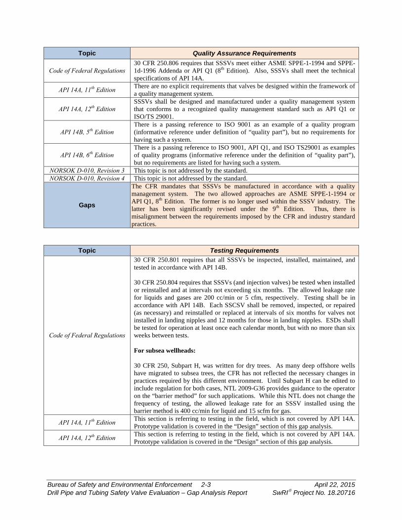
Topic Quality Assurance Requirements
Code of Federal Regulations 30 CFR 250.806 requires that SSSVs meet either ASME SPPE-1-1994 and SPPE-1d-1996 Addenda or API Q1 (8th Edition). Also, SSSVs shall meet the technical specifications of API 14A.
API 14A, 11th Edition There are no explicit requirements that valves be designed within the framework of a quality management system.
API 14A, 12th Edition SSSVs shall be designed and manufactured under a quality management system that conforms to a recognized quality management standard such as API Q1 or ISO/TS 29001.
API 14B, 5th Edition There is a passing reference to ISO 9001 as an example of a quality program (informative reference under definition of “quality part”), but no requirements for having such a system.
API 14B, 6th Edition There is a passing reference to ISO 9001, API Q1, and ISO TS29001 as examples of quality programs (informative reference under the definition of “quality part”), but no requirements are listed for having such a system.
NORSOK D-010, Revision 3 This topic is not addressed by the standard. NORSOK D-010, Revision 4 This topic is not addressed by the standard.
Gaps
The CFR mandates that SSSVs be manufactured in accordance with a quality management system. The two allowed approaches are ASME SPPE-1-1994 or API Q1, 8th Edition. The former is no longer used within the SSSV industry. The latter has been significantly revised under the 9th Edition. Thus, there is misalignment between the requirements imposed by the CFR and industry standard practices.
Topic Testing Requirements
Code of Federal Regulations
30 CFR 250.801 requires that all SSSVs be inspected, installed, maintained, and tested in accordance with API 14B. 30 CFR 250.804 requires that SSSVs (and injection valves) be tested when installed or reinstalled and at intervals not exceeding six months. The allowed leakage rate for liquids and gases are 200 cc/min or 5 cfm, respectively. Testing shall be in accordance with API 14B. Each SSCSV shall be removed, inspected, or repaired (as necessary) and reinstalled or replaced at intervals of six months for valves not installed in landing nipples and 12 months for those in landing nipples. ESDs shall be tested for operation at least once each calendar month, but with no more than six weeks between tests. For subsea wellheads: 30 CFR 250, Subpart H, was written for dry trees. As many deep offshore wells have migrated to subsea trees, the CFR has not reflected the necessary changes in practices required by this different environment. Until Subpart H can be edited to include regulation for both cases, NTL 2009-G36 provides guidance to the operator on the “barrier method” for such applications. While this NTL does not change the frequency of testing, the allowed leakage rate for an SSSV installed using the barrier method is 400 cc/min for liquid and 15 scfm for gas.
API 14A, 11th Edition This section is referring to testing in the field, which is not covered by API 14A. Prototype validation is covered in the “Design” section of this gap analysis.
API 14A, 12th Edition This section is referring to testing in the field, which is not covered by API 14A. Prototype validation is covered in the “Design” section of this gap analysis.
Bureau of Safety and Environmental Enforcement 2-3 April 22, 2015 Drill Pipe and Tubing Safety Valve Evaluation – Gap Analysis Report SwRI Project No. 18.20716
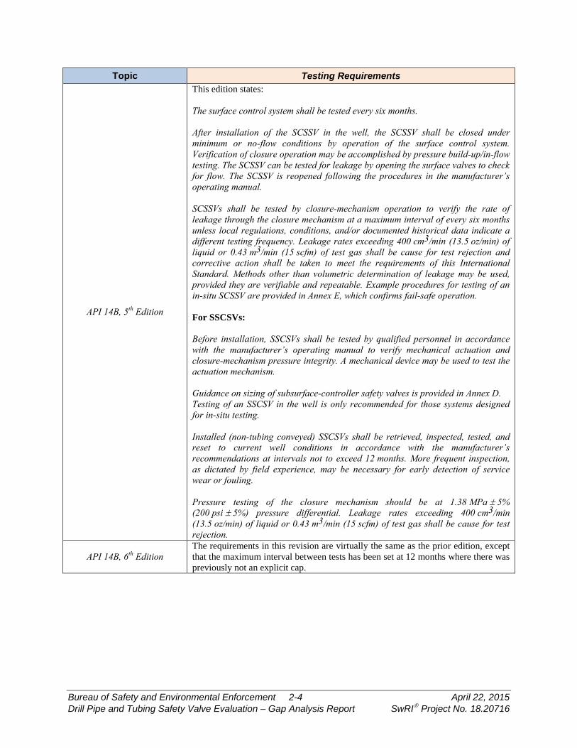
Topic Testing Requirements
API 14B, 5th Edition
This edition states: The surface control system shall be tested every six months. After installation of the SCSSV in the well, the SCSSV shall be closed under minimum or no-flow conditions by operation of the surface control system. Verification of closure operation may be accomplished by pressure build-up/in-flow testing. The SCSSV can be tested for leakage by opening the surface valves to check for flow. The SCSSV is reopened following the procedures in the manufacturer’s operating manual. SCSSVs shall be tested by closure-mechanism operation to verify the rate of leakage through the closure mechanism at a maximum interval of every six months unless local regulations, conditions, and/or documented historical data indicate a different testing frequency. Leakage rates exceeding 400 cm3/min (13.5 oz/min) of liquid or 0.43 m3/min (15 scfm) of test gas shall be cause for test rejection and corrective action shall be taken to meet the requirements of this International Standard. Methods other than volumetric determination of leakage may be used, provided they are verifiable and repeatable. Example procedures for testing of an in-situ SCSSV are provided in Annex E, which confirms fail-safe operation. For SSCSVs: Before installation, SSCSVs shall be tested by qualified personnel in accordance with the manufacturer’s operating manual to verify mechanical actuation and closure-mechanism pressure integrity. A mechanical device may be used to test the actuation mechanism. Guidance on sizing of subsurface-controller safety valves is provided in Annex D. Testing of an SSCSV in the well is only recommended for those systems designed for in-situ testing. Installed (non-tubing conveyed) SSCSVs shall be retrieved, inspected, tested, and reset to current well conditions in accordance with the manufacturer’s recommendations at intervals not to exceed 12 months. More frequent inspection, as dictated by field experience, may be necessary for early detection of service wear or fouling. Pressure testing of the closure mechanism should be at 1.38 MPa ± 5% (200 psi ± 5%) pressure differential. Leakage rates exceeding 400 cm3/min (13.5 oz/min) of liquid or 0.43 m3/min (15 scfm) of test gas shall be cause for test rejection.
API 14B, 6th Edition The requirements in this revision are virtually the same as the prior edition, except that the maximum interval between tests has been set at 12 months where there was previously not an explicit cap.
Bureau of Safety and Environmental Enforcement 2-4 April 22, 2015 Drill Pipe and Tubing Safety Valve Evaluation – Gap Analysis Report SwRI Project No. 18.20716

Topic Testing Requirements
NORSOK D-010, Revision 3
There should be low- and high-differential pressure testing in the direction of the flow upon initial installation. The low-pressure test should be at 1,000 psi. The SSSV shall be tested at specified regular intervals as follows:
• Test duration shall be 30 minutes. • Monthly, until three consecutive qualified tests can be performed. • After three consecutive qualified tests, every three months until three
consecutive qualified tests have been performed. • After three consecutive qualified tests at three-month intervals, the interval
is six months. Allowed leakage rates are 400 cc/min for liquid and 15 scfm for gas. The test can be repeated three times if not meeting the criteria before remedial action is required.
NORSOK D-010, Revision 4 The requirements in this revision are fundamentally the same as Revision 3. The only significant difference is a reference requiring the annual testing of ESDs.
Gaps
The required testing interval varies by jurisdiction. The CFR requires that SSSVs be tested every six months. In Norway, SSSVs must be tested monthly until three consecutive successful tests are achieved. At that point, the interval is quarterly until three consecutive successful tests at that interval are achieved. It is only at that point that a six-month interval is used.
The CFR requirements for allowed leakage through the SSSV are more restrictive than industry standards and Norwegian requirements for dry trees. The allowed leakage for gas and liquid leaks is 5 cfm and 200 cc/min, respectively, in the CFR. These values are 15 scfm and 400 cc/min in all other documents. It should be noted that there is alignment for valves with subsea wellheads, as NTL 2009-G36 provides leakage rate allowances that align with API 14B.
It appears there is an error in the CFR, as a rate with units of cubic-feet-per-minute would be interpreted as a volumetric flow rate at the pressure present at the SSSV. It would be standard practice to state the requirements in terms of a mass flow rate or pseudo-mass flow rate (volumetric rate at standard conditions). A 5-cfm leak has a very different amount of leaked mass than a leak of 5 scfm for the typical range of well pressures.
API 14B provides guidance on how to test SSSVs in applications where direct measurement is not possible. In these instances, a pressure build-up method is used, though there is not direct correlation between the results and the allowed leakage rates. The CFR and NTL 2009-G36 are silent on how to evaluate such applications.
Bureau of Safety and Environmental Enforcement 2-5 April 22, 2015 Drill Pipe and Tubing Safety Valve Evaluation – Gap Analysis Report SwRI Project No. 18.20716

Topic Operations
Code of Federal Regulations
30 CFR 250.803 requires that SSSVs close within two minutes from closure of the SSV (which is required within 45 seconds of detection of an abnormal event). For subsea wellheads: 30 CFR 250, Subpart H, was written for dry trees. As many deep offshore wells have migrated to subsea trees, the CFR has not reflected the necessary changes in practices required by this different environment. Until Subpart H can be edited to include regulation on both cases, NTL 2009-G36 provides guidance to the operator on the “barrier method” for such applications. This NTL has three tables that provide closure time requirements for SSSVs. The closure times vary widely by control type (e.g., electro-hydraulic, direct hydraulic, etc.) and conditions (e.g., process upset, platform emergency, etc.).
API 14A, 11th Edition This topic is outside the scope of API 14A. API 14A, 12th Edition This topic is outside the scope of API 14A.
API 14B, 5th Edition The standard states that the SSSV should be operated per the manufacturer’s or operator’s requirements, but no prescriptive requirements are provided.
API 14B, 6th Edition The standard states that the SSSV should be operated per the manufacturer’s or supplier’s requirements, but no prescriptive requirements are provided.
NORSOK D-010, Revision 3 This topic does not appear to be addressed by the standard. NORSOK D-010, Revision 4 This topic does not appear to be addressed by the standard.
Gaps
30 CFR 250.803 requires that the SSSV be closed within two minutes of closure of the SSV, the latter being required to occur within 45 seconds of an abnormal event. NTL 2009-G36 provides many permutations of allowed closure times. Interestingly, there are no requirements in any industry standard that require the SSSV to be closed within a prescribed time from the onset of abnormal events.
Topic Personnel and Training
Code of Federal Regulations
30 CFR 250.805 requires that personnel installing, inspecting, testing, and maintaining SSSVs be qualified in accordance with 30 CFR 250, subpart O. This subpart does not provide explicit requirements for competence evaluations. However, Subpart S (Safety and Environmental Management Systems) appears to provide more-specific requirements on competency. In 250.1915(d), there is a requirement to “verify that the contractors are trained in the work practices necessary to understand and perform their jobs.”
API 14A, 11th Edition This topic, as it relates to personnel in the field, is outside the scope of API 14A. API 14A, 12th Edition This topic, as it relates to personnel in the field, is outside the scope of API 14A.
API 14B, 5th Edition
All personnel performing installation, redress, testing, and inspection for acceptance shall be qualified in accordance with documented requirements. Personnel performing visual examinations shall have an annual eye examination, as applicable to the discipline to be performed, in accordance with ISO 9712. Personnel performing NDE shall be qualified in accordance with ISO 9712, to at least Level II or equivalent.
API 14B, 6th Edition The requirements in this revision are largely the same as the prior edition.
Bureau of Safety and Environmental Enforcement 2-6 April 22, 2015 Drill Pipe and Tubing Safety Valve Evaluation – Gap Analysis Report SwRI Project No. 18.20716

Topic Personnel and Training
NORSOK D-010, Revision 3
Offshore activities and operations must be monitored and supervised by competent personnel. Competence is established through the following italicized text. The formal requirements should be outlined in the job description for the position. Verification of the individual’s competence can be made through gap analysis, tests, or interviews. A scheduled training program, which may consist of courses, self-study program, or on-the-job training, should be conducted to close gaps. When new equipment will be used, involved personnel shall attend theoretical and practical proficiency training. A reference is made to Norwegian Oil and Gas Association Guideline No. 24, which requires well control personnel to have training per an IWCF or IADC program.
NORSOK D-010, Revision 4
Competence requirements for personnel working with well integrity shall be described. Verification of the individual’s competence can be made through gap analysis, tests, or interviews. A training program, which may consist of courses, e-learning, self-study program, or on-the-job training, should be conducted to close gaps. The position competence curriculum should address the following subjects: a) roles and responsibilities for well integrity management within the company, covering well construction and operational phases; b) wellbore physics (formation integrity, dynamic pressure, and temperature regimes); c) well construction principles, casing design, completion design, and definition of load cases; d) preparation of well handover documentation; e) establishment of a two well barrier principle for the well construction and operational phases with preparation of well barrier schematics; f) operational supervision, frequent testing, monitoring, maintenance, inspection, troubleshooting, diagnostics, annulus pressure management, and trend monitoring. Onsite drilling and well supervisory personnel shall hold a valid well control certificate issued by an international recognized party (i.e., IWCF or IADC). When new equipment or techniques will be used, involved personnel shall attend theoretical and practical proficiency training. All training shall be documented.
Gaps
There is some misalignment of competency requirements for personnel. Subpart O of the CFR does not provide requirements for competency. An indirect set of requirements does appear in Subpart S. Norway requires competency and also that well control operators receive independent certification.
Bureau of Safety and Environmental Enforcement 2-7 April 22, 2015 Drill Pipe and Tubing Safety Valve Evaluation – Gap Analysis Report SwRI Project No. 18.20716
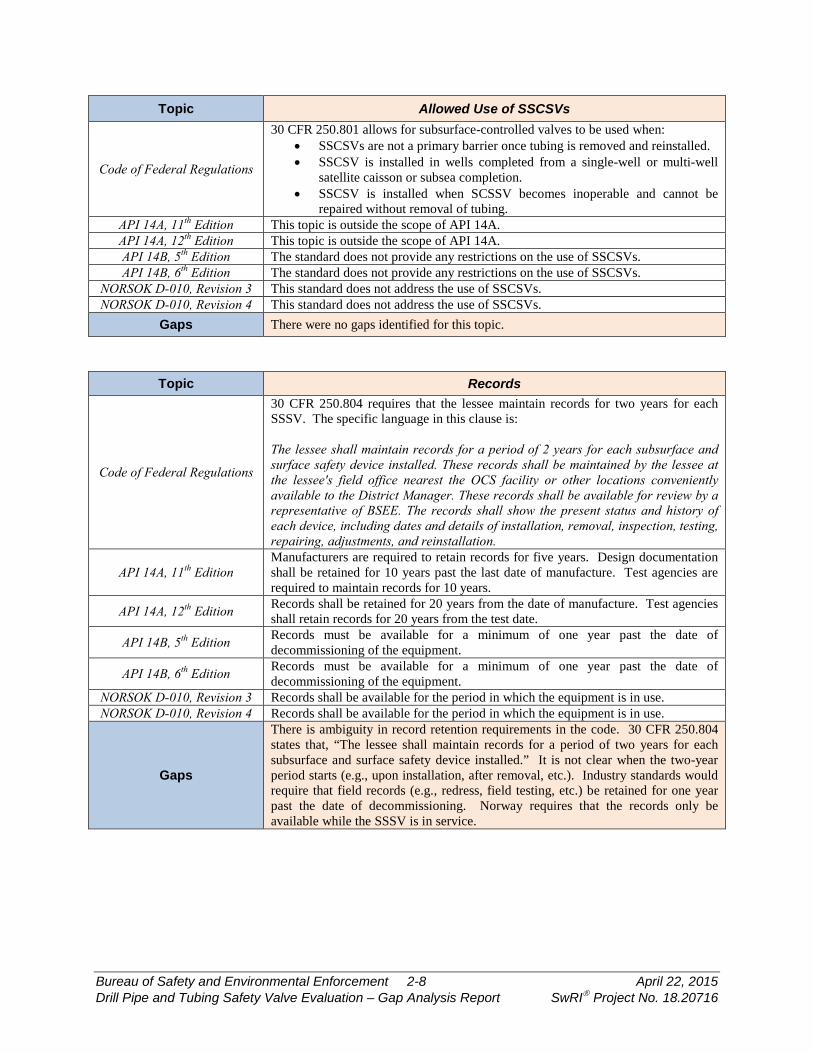
Topic Allowed Use of SSCSVs
Code of Federal Regulations
30 CFR 250.801 allows for subsurface-controlled valves to be used when: • SSCSVs are not a primary barrier once tubing is removed and reinstalled. • SSCSV is installed in wells completed from a single-well or multi-well
satellite caisson or subsea completion. • SSCSV is installed when SCSSV becomes inoperable and cannot be
repaired without removal of tubing. API 14A, 11th Edition This topic is outside the scope of API 14A. API 14A, 12th Edition This topic is outside the scope of API 14A. API 14B, 5th Edition The standard does not provide any restrictions on the use of SSCSVs. API 14B, 6th Edition The standard does not provide any restrictions on the use of SSCSVs.
NORSOK D-010, Revision 3 This standard does not address the use of SSCSVs. NORSOK D-010, Revision 4 This standard does not address the use of SSCSVs.
Gaps There were no gaps identified for this topic.
Topic Records
Code of Federal Regulations
30 CFR 250.804 requires that the lessee maintain records for two years for each SSSV. The specific language in this clause is: The lessee shall maintain records for a period of 2 years for each subsurface and surface safety device installed. These records shall be maintained by the lessee at the lessee's field office nearest the OCS facility or other locations conveniently available to the District Manager. These records shall be available for review by a representative of BSEE. The records shall show the present status and history of each device, including dates and details of installation, removal, inspection, testing, repairing, adjustments, and reinstallation.
API 14A, 11th Edition Manufacturers are required to retain records for five years. Design documentation shall be retained for 10 years past the last date of manufacture. Test agencies are required to maintain records for 10 years.
API 14A, 12th Edition Records shall be retained for 20 years from the date of manufacture. Test agencies shall retain records for 20 years from the test date.
API 14B, 5th Edition Records must be available for a minimum of one year past the date of decommissioning of the equipment.
API 14B, 6th Edition Records must be available for a minimum of one year past the date of decommissioning of the equipment.
NORSOK D-010, Revision 3 Records shall be available for the period in which the equipment is in use. NORSOK D-010, Revision 4 Records shall be available for the period in which the equipment is in use.
Gaps
There is ambiguity in record retention requirements in the code. 30 CFR 250.804 states that, “The lessee shall maintain records for a period of two years for each subsurface and surface safety device installed.” It is not clear when the two-year period starts (e.g., upon installation, after removal, etc.). Industry standards would require that field records (e.g., redress, field testing, etc.) be retained for one year past the date of decommissioning. Norway requires that the records only be available while the SSSV is in service.
Bureau of Safety and Environmental Enforcement 2-8 April 22, 2015 Drill Pipe and Tubing Safety Valve Evaluation – Gap Analysis Report SwRI Project No. 18.20716
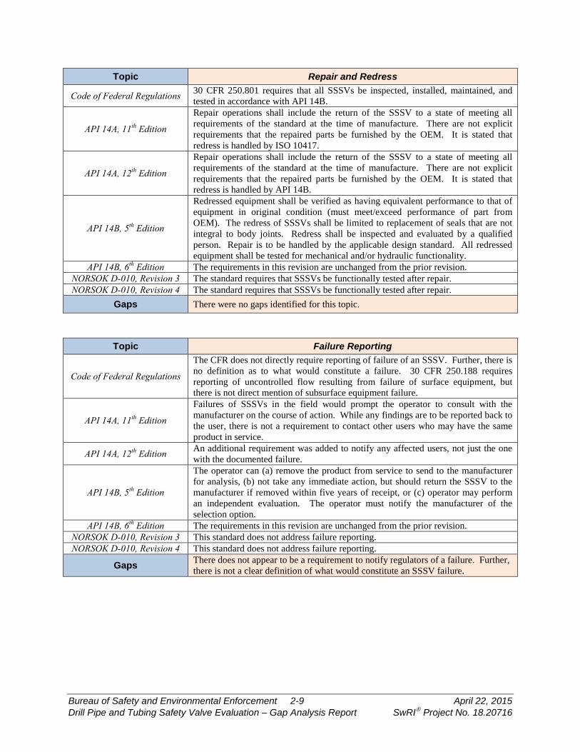
Topic Repair and Redress
Code of Federal Regulations 30 CFR 250.801 requires that all SSSVs be inspected, installed, maintained, and tested in accordance with API 14B.
API 14A, 11th Edition
Repair operations shall include the return of the SSSV to a state of meeting all requirements of the standard at the time of manufacture. There are not explicit requirements that the repaired parts be furnished by the OEM. It is stated that redress is handled by ISO 10417.
API 14A, 12th Edition
Repair operations shall include the return of the SSSV to a state of meeting all requirements of the standard at the time of manufacture. There are not explicit requirements that the repaired parts be furnished by the OEM. It is stated that redress is handled by API 14B.
API 14B, 5th Edition
Redressed equipment shall be verified as having equivalent performance to that of equipment in original condition (must meet/exceed performance of part from OEM). The redress of SSSVs shall be limited to replacement of seals that are not integral to body joints. Redress shall be inspected and evaluated by a qualified person. Repair is to be handled by the applicable design standard. All redressed equipment shall be tested for mechanical and/or hydraulic functionality.
API 14B, 6th Edition The requirements in this revision are unchanged from the prior revision. NORSOK D-010, Revision 3 The standard requires that SSSVs be functionally tested after repair. NORSOK D-010, Revision 4 The standard requires that SSSVs be functionally tested after repair.
Gaps There were no gaps identified for this topic.
Topic Failure Reporting
Code of Federal Regulations
The CFR does not directly require reporting of failure of an SSSV. Further, there is no definition as to what would constitute a failure. 30 CFR 250.188 requires reporting of uncontrolled flow resulting from failure of surface equipment, but there is not direct mention of subsurface equipment failure.
API 14A, 11th Edition
Failures of SSSVs in the field would prompt the operator to consult with the manufacturer on the course of action. While any findings are to be reported back to the user, there is not a requirement to contact other users who may have the same product in service.
API 14A, 12th Edition An additional requirement was added to notify any affected users, not just the one with the documented failure.
API 14B, 5th Edition
The operator can (a) remove the product from service to send to the manufacturer for analysis, (b) not take any immediate action, but should return the SSSV to the manufacturer if removed within five years of receipt, or (c) operator may perform an independent evaluation. The operator must notify the manufacturer of the selection option.
API 14B, 6th Edition The requirements in this revision are unchanged from the prior revision. NORSOK D-010, Revision 3 This standard does not address failure reporting. NORSOK D-010, Revision 4 This standard does not address failure reporting.
Gaps There does not appear to be a requirement to notify regulators of a failure. Further, there is not a clear definition of what would constitute an SSSV failure.
Bureau of Safety and Environmental Enforcement 2-9 April 22, 2015 Drill Pipe and Tubing Safety Valve Evaluation – Gap Analysis Report SwRI Project No. 18.20716
3. CONCLUSIONS
3.1 Summary A review of the CFR and various industry standards revealed several gaps in regulations
and practices for the operation of SSSVs:
• The CFR cites many requirements specific to versions of API standards that are no longer the active. The current standards versions cited are API 14A (11th Edition), API 14B (5th Edition), and API Q1 (8th Edition). These documents have been heavily revised (note: the 6th Edition of API 14B has been approved, but not yet published), so equipment suppliers and end users have two different sets of requirements: industry requirements to use the latest version of these standards and regulations that refer to prior versions of the same standards. 30 CFR 250.198 does provide allowances for using updated versions of standards, as long as particular conditions are met.
• There are no clear requirements in the CFR for evaluating the performance of SSSVs installed in wells in which direct leakage measurement is not possible.
• The omission of HPHT requirements from API 14A (11th Edition) resulted in the inclusion of such requirements in 30 CFR 250.807. The 12th Edition of API 14A appears to have closed these gaps, perhaps rendering 250.807 unnecessary.
• Although ASME SPPE-1-1994 is cited in 30 CFR 250.806, it is not part of the quality management programs utilized by the industry.
• Norway requires more-frequent testing for SSSVs early in their service life than the CFR. The CFR requires that SSSVs be tested every six months. In Norway, SSSVs must be tested monthly until three consecutive successful tests are achieved. At that point, the interval is quarterly until three consecutive successful tests at that interval are achieved. It is only at that point that a six-month interval is used.
• While there is general alignment of allowed leakage rates for SSSVs, the CFR has essentially created a more-stringent set of requirements for SSSVs in wells with dry trees. This narrower range of allowed leakage does not appear anywhere else. It should be noted that the units for this leak rate (cfm) do not align with other requirements in the CFR or industry standards for this equipment (use of scfm).
• There is inconsistency in the required closure time for an SSSV, depending on the control signal type, reason for closure, and type of wellhead. Further, there are no requirements within design and operating standards driving valve suppliers and users to ensure that SSSVs will be able to meet these requirements.
• There is some misalignment of competency requirements for personnel. Subpart O of the CFR does not provide requirements for competency. An indirect set of requirements does appear in Subpart S. Norway requires competency and also that well control operators receive independent certification.
• There is inconsistency in the records retention requirements in the CFR, industry standards, and Norwegian requirements. Further, the CFR gives a time period, but does not note “when the clock starts.”
Bureau of Safety and Environmental Enforcement 3-1 April 22, 2015 Drill Pipe and Tubing Safety Valve Evaluation – Gap Analysis Report SwRI Project No. 18.20716
• There does not appear to be a requirement to notify regulators of a failure. Further, there is not a clear definition of what would constitute an SSSV failure.
3.2 Path Forward The next task on this project will be to develop recommendations for edits to the CFR
that would aid in closing some of these gaps.
Bureau of Safety and Environmental Enforcement 3-2 April 22, 2015 Drill Pipe and Tubing Safety Valve Evaluation – Gap Analysis Report SwRI Project No. 18.20716
4. REFERENCES
API Recommended Practice 14B, 5th Edition, “Design, Installation, Repair, and Operation of Subsurface Safety Valves Systems,” 2005.
API Recommended Practice 14B, 6th Edition, “Design, Installation, Operation, Test and Redress of Subsurface Safety Valve Systems,” 2015 (proposed).
API Specification 14A, 11th Edition, “Specification for Subsurface Safety Valve Equipment,” 2005.
API Specification 14A, 12th Edition, “Specification for Subsurface Safety Valve Equipment,” 2015.
Notice to Lessees and Operators, NTL 2009-G36, “Using Alternate Compliance in Safety Systems for Subsea Production Operations.”
NORSOK Standard D-010, “Well integrity in drilling and well operations,” Revision 3, August 2004.
NORSOK Standard D-010, “Well integrity in drilling and well operations,” Revision 4, June 2013.
Norway Petroleum Safety Authority, “Regulations Relating to Design and Outfitting of Facilities, etc. in the Petroleum Activities,” December 2013.
Norwegian Oil and Gas Association Guideline No. 24, “Recommended Guidelines for Competence Requirements for Drilling and Well Service Personnel,” Revision 5, June 2013.
U.S. Code of Federal Regulations through www.ecfr.gov.
Bureau of Safety and Environmental Enforcement 4-1 April 22, 2015 Drill Pipe and Tubing Safety Valve Evaluation – Gap Analysis Report SwRI Project No. 18.20716