Embed Size (px)
Citation preview

Operating Instructions
DJ MIXER
DJM-800

2
The exclamation point within an equilateral triangle is intended to alert the user to the presence of important operating and maintenance (servicing) instructions in the literature accompanying the appliance.
The lightning flash with arrowhead symbol, within an equilateral triangle, is intended to alert the user to the presence of uninsulated "dangerous voltage" within the product's enclosure that may be of sufficient magnitude to constitute a risk of electric shock to persons.
CAUTION:TO PREVENT THE RISK OF ELECTRIC SHOCK, DO NOT REMOVE COVER (OR BACK). NO USER-SERVICEABLE PARTS INSIDE. REFER SERVICING TO QUALIFIED SERVICE PERSONNEL.
CAUTIONRISK OF ELECTRIC SHOCK
DO NOT OPEN
IMPORTANT
D1-4-2-3_En-A
Read these instructions.Keep these instructions.Heed all warnings.Follow all instructions.Do not use this apparatus near water.Clean only with dry cloth.Do not block any ventilation openings. Install in accordance with the manufacturer’s instructions.Do not install near any heat sources such as radiators, heat registers, stoves, or other apparatus (including amplifiers) that produce heat.Do not defeat the safety purpose of the polarized or grounding-type plug. A polarized plug has two blades with one wider than the other. A grounding type plug has two blades and a third grounding prong. The wide blade or the third prong are provided for your safety. If the provided plug does not fit into your outlet, consult an electrician for replacement of the obsolete outlet.Protect the power cord from being walked on or pinched particularly at plugs, convenience receptacles, and the point where they exit from the apparatus.
1) 2) 3) 4) 5) 6) 7)
8)
9)
10)
Only use attachments/accessories specified by the manufacturer.Use only with the cart, stand, tripod, bracket, or table specified by the manufacturer, or sold with the apparatus. When a cart is used, use caution when moving the cart/apparatus combination to avoid injury from tip-over.
Unplug this apparatus during lightning storms or when unused for long periods of time.Refer all servicing to qualified service personnel. Servicing is required when the apparatus has been damaged in any way, such as power-supply cord or plug is damaged, liquid has been spilled or objects have fallen into the apparatus, the apparatus has been exposed to rain or moisture, does not operate normally, or has been dropped. P1-4-2-2_En
11)
12)
13)
14)
NOTE: This equipment has been tested and found to comply with the limits for a Class B digital device, pursuant to Part 15 of the FCC Rules. These limits are designed to provide reasonable protection against harmful interference in a residential installation. This equipment generates, uses, and can radiate radio frequency energy and, if not installed and used in accordance with the instructions, may cause harmful interference to radio communications. However, there is no guarantee that interference will not occur in a particular installation. If this equipment does cause harmful interference to radio or television reception, which can be determined by turning the equipment off and on, the user is encouraged to try to correct the interference by one or more of the following measures:
– Reorient or relocate the receiving antenna. – Increase the separation between the equipment and receiver. – Connect the equipment into an outlet on a circuit different from that to which the receiver is connected. – Consult the dealer or an experienced radio/TV technician for help. D8-10-1-2_En
Thank you for buying this Pioneer product.Please read through these operating instructions so you will know how to operate your model properly. After you have finished readingthe instructions, put them away in a safe place for future reference.In some countries or regions, the shape of the power plug and power outlet may sometimes differ from that shown in the explanatorydrawings. However the method of connecting and operating the unit is the same. K015 En
WARNINGThis equipment is not waterproof. To prevent a fire or shock hazard, do not place any container filed with liquid near this equipment (such as a vase or flower pot) or expose it to dripping, splashing, rain or moisture. D3-4-2-1-3_A_En
IMPORTANT NOTICE – THE SERIAL NUMBER FOR THIS EQUIPMENT IS LOCATED IN THE REAR. PLEASE WRITE THIS SERIAL NUMBER ON YOUR ENCLOSED WARRANTY CARD AND KEEP IN A SECURE AREA. THIS IS FOR YOUR SECURITY.
D1-4-2-6-1_En
This Class B digital apparatus complies with Canadian ICES-003.
Cet appareil numérique de la Classe B est conforme à la norme NMB-003 du Canada. D8-10-1-3_EF
Information to UserAlteration or modifications carried out without appropriate authorization may invalidate the user’s right to operate the equipment. D8-10-2_En
CAUTION: This product satisfies FCC regulations when shielded cables and connectors are used to connect the unit to other equipment. To prevent electromagnetic interference with electric appliances such as radios and televisions, use shielded cables and connectors for connections. D8-10-3a_En
CAUTION – PREVENT ELECTRIC SHOCK DO NOT USE THIS (POLARIZED) PLUG WITH AN EXTENSION CORD.
RECEPTACLE OR OTHER OUTLET UNLESS THE BLADES CAN BE FULLY INSERTED TO PREVENT BLADE EXPOSURE.
ATTENTION – POUR PREVENIR LES CHOCS ELECTRIQUES NE PAS UTILISER CETTE FICHE POLARISEE AVEC UN PROLONGATEUR UNE PRISE DE COURANT OU UNE AUTRE SORTIE DE COURANT, SAUF SI LES LAMES PEUVENT ETRE INSEREES A FOND SANS EN LAISSER AUCUNE PARTIE A DECOUVVERT. D2-4-4-1_EF
WARNING: Handling the cord on this product or cords associated with accessories sold with the product will expose you to chemicals listed on proposition 65 known to the State of California and other governmental entities to cause cancer and birth defect or other reproductive harm.Wash hands after handling D36-P4_A_En
WARNINGTo prevent a fire hazard, do not place any naked flame sources (such as a lighted candle) on the equipment. D3-4-2-1-7a_A_En
VENTILATION CAUTIONWhen installing this unit, make sure to leave space around the unit for ventilation to improve heat radiation (at least 5 cm at rear, and 3 cm at each side).WARNINGSlots and openings in the cabinet are provided for ventilation to ensure reliable operation of the product, and to protect it from overheating. To prevent fire hazard, the openings should never be blocked or covered with items (such as newspapers, table-cloths, curtains) or by operating the equipment on thick carpet or a bed. D3-4-2-1-7b_A_En
POWER-CORD CAUTIONHandle the power cord by the plug. Do not pull out the plug by tugging the cord and never touch the power cord when your hands are wet as this could cause a short circuit or electric shock. Do not place the unit, a piece of furniture, etc., on the power cord, or pinch the cord. Never make a knot in the cord or tie it with other cords. The power cords should be routed such that they are not likely to be stepped on. A damaged power cord can cause a fire or give you an electrical shock. Check the power cord once in a while. When you find it damaged, ask your nearest PIONEER authorized service center or your dealer for a replacement. S002_En

3
Location
Install the unit in a well-ventilated location where it will not
be exposed to high temperatures or humidity.
÷ Do not install the unit in a location which is exposed todirect rays of the sun, or near stoves or radiators. Excessiveheat can adversely affect the cabinet and internalcomponents. Installation of the unit in a damp or dustyenvironment may also result in a malfunction or accident.(Avoid installation near cookers etc., where the unit may beexposed to oily smoke, steam or heat.)
÷ When the unit is used inside a carrying case or DJ booth,separate it from the walls or other equipment to improveheat radiation.
CAUTIONS REGARDING HANDLING
Cleaning the Unit
÷ Use a polishing cloth to wipe off dust and dirt.÷ When the surfaces are very dirty, wipe with a soft cloth
dipped in some neutral cleanser diluted five or six timeswith water and wrung out well, then wipe again with a drycloth. Do not use furniture wax or cleaners.
÷ Never use thinners, benzene, insecticide sprays or otherchemicals on or near this unit, since these will corrode thesurfaces.
S001_En
Selecting fine audio equipment such as the unit you’ve just purchased is only the start of your musical enjoyment. Now it’s time to consider how you can maximize the fun and excitement your equipment offers. This manufacturer and the Electronic Industries Association’s Consumer Electronics Group want you to get the most out of your equipment by playing it at a safe level. One that lets the sound come through loud and clear without annoying blaring or distortion-and, most importantly, without affecting your sensitive hearing.
Sound can be deceiving. Over time your hearing “comfort level” adapts to higher volumes of sound. So what sounds “normal” can actually be loud and harmful to your hearing. Guard against this by setting your equipment at a safe level BEFORE your hearing adapts.
To establish a safe level: • Start your volume control at a low setting.• Slowly increase the sound until you can hear it
comfortably and clearly, and without distortion.
Once you have established a comfortable sound level:• Set the dial and leave it there.
Taking a minute to do this now will help to prevent hearing damage or loss in the future. After all, we want you listening for a lifetime.
We Want You Listening For A Lifetime
Used wisely, your new sound equipment will provide a lifetime of fun and enjoyment. Since hearing damage from loud noise is often undetectable until it is too late, this manufacturer and the Electronic Industries Association’s Consumer Electronics Group recommend you avoid prolonged exposure to excessive noise. This list of sound levels is included for your protection.
DecibelLevel Example
30 Quiet library, soft whispers 40 Living room, refrigerator, bedroom away from traffic 50 Light traffic, normal conversation, quiet office 60 Air conditioner at 20 feet, sewing machine 70 Vacuum cleaner, hair dryer, noisy restaurant 80 Average city traffic, garbage disposals, alarm clock at two feet.
THE FOLLOWING NOISES CAN BE DANGEROUS UNDER CONSTANT EXPOSURE
90 Subway, motorcycle, truck traffic, lawn mower 100 Garbage truck, chain saw, pneumatic drill 120 Rock band concert in front of speakers, thunderclap 140 Gunshot blast, jet plane 180 Rocket launching pad
Information courtesy of the Deafness Research Foundation.

4
FEATURESCONTENTS
CONFIRM ACCESSORIES
1 Designed for high sound qualityAnalog signals are transmitted by the shortest circuitry andconverted to digital format at 96 kHz sampling rate via a 24-bit highquality A/D converter. As a result, signals are passed to the digitalmixing stage in the best possible state. Mixing is performed with a32-bit DSP, totally eliminating any loss in fidelity, while the ideal levelof filtering is introduced to produce optimum sound for DJ play.These features are housed in a high-rigidity chassis with double-shielded construction together with a high-performance powersection and other features of the high-fidelity technology also used inthe DJM-1000, thus guaranteeing the utmost in clear and powerfulclub sounds.
2 Sound-color effects1) Harmonic effectEquipped with the industry’s first “harmonic effect” function thatdetects the track’s key and provides optimum tuning for DJ play.This new function allows smoother, more natural DJ mixingcompared to earlier models which allowed DJ play with track tempoadjustment alone.
2) Modulation effect“Filter,” “crush,” and “sweep” effects have been added to eachchannel.These allow a greater breadth to DJ play by permitting the user toapply effects more intuitively.Also, by combining these with “beat effects,” some 50 kinds of effectcan be produced, giving the user a vast potential for remix and DJplay.
3 Beat effectsThe “beat effects” so popular on the DJM-600 are continued here.Effects can be applied in linkage to the BPM (Beats Per Minute) count,thus allowing the production of a variety of sounds.Some of the effects include delay, echo, reverse delay, pan, trance,filter, flanger, phaser, reverb, robot, chorus, roll, and reverse roll.
4 Digital IN/OUTThe digital input connectors support each of the sampling rates (44.1/48/96 kHz), thus allowing the connection of digital components for aDJ system with no sound degradation.Likewise the digital output connectors support sampling rates 96 kHz/24-bit and 48 kHz/24-bit, making the unit even more convenient forcutting studio tracks or on other occasions when high sound fidelityis required. (Only linear PCM is supported.)
5 MIDI OUTVirtually all the dial and switch information of the DJM-800 can beoutput in MIDI signal format, allowing external components to becontrolled via MIDI.
6 Other functions¶ A control cable can be used to connect the unit to a Pioneer DJ CD
player, thus allowing playback to be linked to operation of thefader (“fader start play”).
¶ Built-in “3-band equalizer” supports level control within the rangeof +6 dB to –26 dB in each bandwidth.
¶ “Cross fader assignment” function allows each channel’s input tobe assigned flexibly to a cross fader.
¶ “Talk over” function automatically lowers track volume duringmicrophone input.
¶ “Fader curve adjustment” function allows modification of thecross fader and channel fader curves.
¶ “Microphone cut” function mutes microphone output to thebooth monitor, thus preventing uncomfortable feedback.
¶ By replacing the channel fader section with the optional rotaryvolume kit DJC-800RV, the slider control can be replayed with arotary type control.
CAUTIONS REGARDING HANDLING ........................ 3CONFIRM ACCESSORIES ........................................... 4FEATURES ................................................................... 4
BEFORE USING
CONNECTIONS............................................................ 5CONNECTION PANEL ........................................... 5CONNECTING INPUTS .......................................... 6CONNECTING EXTERNAL EFFECTORS,OUTPUT CONNECTORS ....................................... 7ABOUT MIDI CONNECTORS ................................ 7CONNECTING MICROPHONE ANDHEADPHONES........................................................ 8CONNECTING THE POWER CORD ...................... 8
NAMES AND FUNCTIONS OF PARTS ...................... 9OPERATION PANEL............................................... 9DISPLAY SECTION .............................................. 12
OPERATIONS
MIXER OPERATIONS ................................................ 13BASIC OPERATIONS ........................................... 13FADER START FUNCTION .................................. 14
EFFECT FUNCTIONS ................................................. 15TYPES OF BEAT EFFECTS .................................. 15PRODUCING BEAT EFFECTS.............................. 17TYPE OF SOUND-COLOR EFFECT ..................... 18USING SOUND-COLOR EFFECTS ...................... 18EFFECT PARAMETERS ........................................ 19
MIDI SETTINGS ......................................................... 20SYNCHRONIZING AUDIO SIGNALS TOEXTERNAL SEQUENCER, OR USINGDJM-800 INFORMATION TO OPERATEAN EXTERNAL SEQUENCER.............................. 20MIDI MESSAGES ................................................. 20PROGRAM CHANGE ........................................... 21SNAPSHOT........................................................... 21
OTHER
TROUBLESHOOTING ................................................ 22SPECIFICATIONS ....................................................... 23BLOCK DIAGRAM ...................................................... 24
Operating Instructions........................................................... 1Power cord ............................................................................. 1Warranty ................................................................................. 1

5
CONNECTION PANEL
1. POWER switch
2. MASTER 2 output connectorsRCA type unbalanced output.
3. Recording output connectors (REC)RCA type output connectors for recording.
4. PHONO input connectorsRCA type phono level (MM cartridge) input connectors.Do not use for inputting line level signals.
5. LINE input connectorsRCA type line level input connectors.Use to connect a cassette deck or other line level output component.
6. Signal grounding terminals (SIGNAL GND)Use to connect ground wires from analog players.This is not a safety grounding terminal.
7. CD input connectorsRCA type line level input connectors.Use to connect a DJ CD player or other line level output component.
8. DIGITAL IN connectorsRCA type digital coaxial input connectors.Use to connect to DJ CD player or other digital coaxial outputconnectors.
9. MIDI OUT connectorDIN type output connector.Use to connect to other MIDI component (see P. 20).
10. DIGITAL OUT connectorRCA type digital coaxial output connector.Master audio digital output.
11. Sampling frequency selector switch (fs 48 k/96 k)Use to set the sampling frequency of the digital output to 96 kHz/24-bit or 48 kHz/24-bit.
12. DIGITAL/CD input selector switchesUse to select either analog input (CD) or digital input (DIGITAL IN).
13. RETURN connectorsØ6.3 mm phone-type input connectors.Use to connect to the output connectors of external effectors orsimilar components.When the L channel only is connected, the L channel input issimultaneously input to the R channel.
14. SEND output connectorsØ6.3 mm phone-type output connectors.Use to connect to the input connectors of external effectors or othersimilar components. When the L channel only is connected, a L+Rmonaural signal is output.
15. CONTROL connectorsØ3.5 mm mini-connector. Use to connect to the control connector ofa Pioneer DJ CD player.When the connectors are connected, the DJM-800’s fader can beused to perform start/stop on the DJ CD player.
16. BOOTH monitor output connectorsØ6.3 mm phone-type booth monitor output connectors.The sound level from these connectors is controlled independentlyby the BOOTH MONITOR level dial, regardless of the position of theMASTER LEVEL dial. (These connectors are TRS output, so theysupport both balanced and unbalanced outputs.)
17. DIGITAL/LINE input selector switchesUse to select either analog input (LINE) or digital input (DIGITAL IN).
18. Master output attenuator switch (MASTER ATT)Use to attenuate the level of the master 1 and master 2 outputs.Selectable values are 0 dB, –3 dB, –6 dB and –12 dB.
19. Microphone signal switch(MIC SIGNAL ADD/CUT)
When set to the [ADD] position, the sounds from microphone 1 andmicrophone 2 are output to the BOOTH monitor output connectors.When set to the [CUT] position, the sounds from microphone 1 andmicrophone 2 are not output to the BOOTH monitor outputconnectors.
20. MASTER 1 output connectorsXLR type (male) balanced output.÷ When using a cord with RCA-type plug, users are recommended
to connect the plug directly to the MASTER 2 connectors withoutusing an XLR/RCA converter plug.
21. Power inlet (AC IN)Use the accessory power cord to connect to an AC power outlet of theproper voltage.
CONNECTIONS
POWER
MASTER 2 REC
R L R (TRS) LMASTER 1
L
R
PHONO
CONTROL
DIGITAL
MIC SIGNALCUTADD
SIGNAL GND SIGNAL GND
LINEDIGITAL
LINEDIGITAL
CDDIGITAL
CD
LINEL
R
AC IN
OFF ON
1GND
3COLD
MASTER ATT
2HOT
PHONO
CONTROL
BOOTH R L(MONO)SEND R L(MONO)RETURN
LINEL
R
PHONO
CONTROL
CDL
R
LINE
CONTROL
DIGITAL OUT
MIDI OUT
fs (Hz)
48 k 96 k
CDL
R
-12dB-6dB
-3dB0dB
DIGITAL IN
1 2 3 4 5 6 8
9101113 121415161718192021
7
CONNECTIONS (CONNECTION PANEL)

6
POWER
MASTER 2 REC
R L R (TRS) LMASTER 1
L
R
PHONO
CONTROL
DIGITAL
MIC SIGNALCUTADD
SIGNAL GND SIGNAL GND
LINEDIGITAL
LINEDIGITAL
CDDIGITAL
CD
LINEL
R
AC IN
OFF ON
1GND
3COLD
MASTER ATT
2HOT
PHONO
CONTROL
BOOTH R L(MONO)SEND R L(MONO)RETURN
LINEL
R
PHONO
CONTROL
CDL
R
LINE
CONTROL
DIGITAL OUT
MIDI OUT
fs (Hz)
48 k 96 k
CDL
R
-12dB-6dB
-3dB0dB
DIGITAL IN
LR L RL R L RL RL R
Always turn off the power switch and disconnect the power plug from its outlet when making or changing connections.
CONNECTING INPUTS
Pioneer DJ CD playersConnect a DJ CD player’s audio output connectors to one of thechannel 1 to 2 CD input connectors or the channel 3 to 4 LINE inputconnectors, and connect the player’s control cable to thecorresponding channel’s CONTROL connector.Set the connected channel’s DIGITAL/CD switch or DIGITAL/LINE
switch to either [CD] or [LINE], and set the input selector switch to[CD/DIGITAL] or [LINE/DIGITAL].When making digital connections, connect the digital coaxial outputterminal of the DJ CD player to one of the channel 1 to 4 DIGITAL IN
connectors of the DJM-800; then set the corresponding channel’sDIGITAL/CD switch or DIGITAL/LINE switch to [DIGITAL], and theinput selector switch to [CD/DIGITAL] or [LINE/DIGITAL].
Analog turntableTo connect an analog turntable, connect the turntable’s audiooutput cable to one of the channel 2 to 4 PHONO input connectors.Set the corresponding channel’s input selector switch to [PHONO].The DJM-800’s PHONO inputs support MM cartridges.Connect the turntable’s ground wire to one of the DJM-800’sSIGNAL GND terminals.÷ Note that no PHONO input connector is provided for channel 1.
Connecting other line level output devicesTo use a cassette deck or other CD player, connect the component’saudio output connectors to one of the channel 3 to 4 LINE inputconnectors. Then set the corresponding channel’s DIGITAL/LINE
switch to [LINE], and the input selector switch to [LINE/DIGITAL].Alternately, connect the component to the channel 1 LINE inputconnector, then set the channel 1 input selector switch to [LINE].
Connecting other digital output devicesTo use a CD player or other component with digital connections,connect the component’s digital coaxial output connectors to one ofthe channel 1 to 4 DIGITAL IN connectors; then set the correspondingchannel’s DIGITAL/CD switch or DIGITAL/LINE switch to [DIGITAL],and the input selector switch to [CD/DIGITAL] or [LINE/DIGITAL].
Input selector switch
DIGITAL/CD switch
Analog turntable DJ CD player
CD player, etc.
Cassette deck, etc.Analog turntable DJ CD player
CONNECTIONS (CONNECTING INPUTS)
DIGITAL/LINE switch

7
POWER
MASTER 2 REC
R L R (TRS) LMASTER 1
L
R
PHONO
CONTROL
DIGITAL
MIC SIGNALCUTADD
SIGNAL GND SIGNAL GND
LINEDIGITAL
LINEDIGITAL
CDDIGITAL
CD
LINEL
R
AC IN
OFF ON
1GND
3COLD
MASTER ATT
2HOT
PHONO
CONTROL
BOOTH R L(MONO)SEND R L(MONO)RETURN
LINEL
R
PHONO
CONTROL
CDL
R
LINE
CONTROL
DIGITAL OUT
MIDI OUT
fs (Hz)
48 k 96 k
CDL
R
-12dB-6dB
-3dB0dB
DIGITAL IN
L RLR
CONNECTING EXTERNAL EFFECTORS, OUTPUT CONNECTORS
Master outputThis unit is furnished with balanced output MASTER 1 (supportingXLR plugs), and unbalanced output MASTER 2 (supporting RCAplugs).Using the MASTER ATT switch, adjust the output level to match theinput sensitivity of the power amplifier used.If the operating panel’s STEREO/MONO switch is set to [MONO], themaster output will be a monaural combination of L+R channels.
Booth monitor outputThis is a TRS output supporting Ø6.3 mm phone plugs. The soundvolume for this output is controlled by the BOOTH MONITOR leveldial, independently of the master output level setting.
Recording outputThese are output connectors for recording, supporting RCA plugs.
ABOUT MIDI CONNECTORS
See P.20 regarding the functions of MIDI connectors.
Power amplifier
(RCA plug input connectors)
Cassette deck
(analog input recording device)
Digital input AV amplifier
(digital input recording device)
External effectorPower amplifier
(XLR plug input connectors)
MASTER ATT
switch
Power amplifier
(for booth monitor)
Digital outputThis is a coaxial digital output connector, supporting RCA plugs. Thesampling frequency can be set to 96 kHz/24-bit or 48 kHz/24-bit tomatch the connected device.
External effectorUse a cable with Ø6.3 mm phone plugs to connect the DJ mixer’sSEND connectors to the effector’s input connectors.When using an effector with monaural inputs, connect only to the DJmixer’s L channel output. In this way, the mixed L+R audio signal willbe sent to the effector. In the same way, use a cable with Ø6.3 mmphone plugs to connect the DJ mixer’s RETURN connectors to theoutput connectors of the effector.If the effector has only monaural output, connect to the DJ mixer’s Lchannel input only. The signal from the effector will be input to both Land R channels.When using an external effector, set the effect selector to [SND/RTN].
Sampling frequency selector switch
CONNECTIONS (CONNECTING EXTERNAL EFFECTORS, OUTPUT CONNECTORS/ABOUT MIDI CONNECTORS)

8
CONNECTING MICROPHONE AND HEADPHONES
MicrophoneThe MIC 1 jack on the upper surface of the operating panel can beused to connect a microphone with Ø6.3 mm phone plug or XLRplug.The MIC 2 jack on the upper surface of the operating panel can beused to connect a microphone with Ø6.3 mm phone plugs.¶ When the connection panel’s MIC SIGNAL switch is set to [CUT],
no microphone sounds will be output from the BOOTH monitoroutput connectors.
HeadphonesThe PHONES jack on the upper surface of the operating panel can beused to connect headphones with a Ø6.3 mm stereo phone plug.
0
+6-12
MIC 1LEVEL
MIC 1 MIC 2
0
HI
EQ
MIC
LOW
MIC
+6
OFF ON TALKOVER
-12
MIC 2LEVEL
Microphone 1
Microphone 2
(Microphone 1)
Headphones
HEADPHONES
MIXING
LEVEL
PHONES
MONO SPLIT STEREO
MASTERCUE
0
CONNECTIONS (CONNECTING MICROPHONE AND HEADPHONES/CONNECTING THE POWER CORD)
CONNECTING THE POWER CORD
Connect the power cord last.
÷ After completing all other connections, connect the accessory power cord to the AC inlet on the back of the player, then connect the plug to astandard wall outlet or to the auxiliary power outlet of your amplifier.
÷ Use only the supplied power cord.

9
OPERATION PANEL
Microphone input control section
1. Microphone 1 input jack (MIC 1)Use to connect a microphone with an XLR or phone plug.
2. Microphone 2 input jack (MIC 2)Use to connect a microphone with a phone plug.
3. Microphone 1 level control dial(MIC 1 LEVEL)
Use to adjust the volume of microphone 1. (adjustable range–∞ to 0 dB)
4. Microphone 2 level control dial(MIC 2 LEVEL)
Use to adjust the volume of microphone 2. (adjustable range–∞ to 0 dB)
5. Microphone equalizer high-range control dial (HI)Use to adjust the treble (high-range) frequencies ofmicrophones 1 and 2. (adjustable range –12 dB to +6 dB)
6. Microphone equalizer low-range control dial(LOW)
Use to adjust the bass (low-range) frequencies ofmicrophones 1 and 2. (adjustable range –12 dB to +6 dB)
7. Microphone function indicatorLights when microphone is ON; flashes when TALK OVER isON.
8. Microphone function selector switch (MIC)OFF:
No microphone sound is output.ON:
Microphone sound is output normally.TALK OVER:
Microphone sound is output; when sound is input to aconnected microphone, the TALK OVER function operatesand all sound other than that from the microphone isattenuated by 20 dB.
Channel input control section
9. Channel 1 input selector switchCD/DIGITAL:
Use to select CD input connectors (line level analog input) orDIGITAL input connectors.LINE:
Use to select LINE input connectors.
10. Channel 2 to 4 input selector switchesCD/DIGITAL (channel 2):
Use to select CD input connectors (line level analog input) orDIGITAL input connectors.LINE/DIGITAL (channel 3 to 4):
Use to select LINE input connectors (line level analog input) orDIGITAL input connectors.PHONO:
Use to select PHONO input connectors (analog turntableinput).
NAMES AND FUNCTIONS OF PARTS
0
+6-12
LINE
TRIM
MIC 1LEVEL
MIC 1 MIC 2
0
HI
EQ
MIC
SOUND COLOR FX
1 2 3 4
FADER START
HEADPHONES
LOW
MIC MASTER
BEAT EFFECTS
HI
CD/DIGITAL PHONO
CD/DIGITAL PHONO
LINE/DIGITAL PHONO
LINE/DIGITAL
+9
+6-26MID
+6
+6
OFF ON
HARMONIC SWEEP
FILTERCRUSH
TALKOVER
-12
-26LOW
+6-26dB dB dB dB
COLOR
MIXING
LEVEL
PHONESCROSS FADER ASSIGN
CUE
HI
MONO SPLIT STEREO
MASTERCUE
109876543210
109876543210
109876543210
LOW
MIC 2LEVEL
0
OVER
10
7
4
2
1
0
–1
–2
–3
–5
–7
–10
–15
–24
TRIM
HI+9
+6-26MID
+6-26LOW
+6-26
CUE
OVER
10
7
4
2
1
0
–1
–2
–3
–5
–7
–10
–15
–24
TRIM
HI+9
+6-26MID
+6-26LOW
+6-26
PROFESSIONAL MIXER
CUE CUE
CUE
A THRU B
MONO STEREO
LEVEL/DEPTH
TIME
MAX
ON/OFFMIN
BOOTH MONITOR
CH FADER
CROSS FADER
BEAT
AUTO/TAPMIDI START
/STOP
DELAY
12
3 4 MICCF.A
CF.B
MASTER
REV DLYREV ROLL
PANROLL
TRANSCHORUS
FILTERROBOT
FLANGERREVERB
PHASER
ECHO
SND/RTN
OVER
10
7
4
2
1
0
–1
–2
–3
–5
–7
–10
–15
–24
OVER
10
7
4
2
1
0
–1
–2
–3
–5
–7
–10
–15
–24
L RdB
TRIM
HI+9
+6-26MID
+6-26LOW
+6-26
CUE
OVER
10
7
4
2
1
0
–1
–2
–3
–5
–7
–10
–15
–24
A B
TAP
EQ EQ EQ EQ
COLOR
HILOW
COLOR
HILOW
COLOR
HILOW
BALANCE
RL
A THRU BA THRU BA THRU B
LEVEL
0
POWER
0
3
4
5
6
29
30
78
11
13
14
42
11
13
14
11
13
14
11
13
14
16
17
16 16 16 16
18 18 18 1819 19 19 19 20
21
28
31
24
23
25
26
27
35
34 33
32
36
39
38
37
40
4342
4342
4342
43
449 10 10 10
22
12
12 12 12 12
15 15 15 15
1641
NAMES AND FUNCTIONS OF PARTS (OPERATION PANEL)

10
11. TRIM adjust dialUse to adjust the input level for each channel. (adjustablerange: –∞ to +9 dB, mid-position is about 0 dB)
12. Channel equalizer high-range adjust dial (HI)Use to adjust the treble (high-range) frequency sound for eachchannel. (adjustable range: –26 dB to +6 dB)
13. Channel equalizer mid-range adjust dial (MID)Use to adjust the mid-range frequency sound for eachchannel. (adjustable range: –26 dB to +6 dB)
14. Channel equalizer low-range adjust dial (LOW)Use to adjust the bass (low-range) frequency sound for eachchannel. (adjustable range: –26 dB to +6 dB)
15. Channel level indicatorDisplays the current level for each channel, with two-secondpeak hold.
16. Headphone CUE buttons/indicatorsThese buttons are used to select from channel 1 to 4,MASTER, or effector, to allow you to monitor the desiredsource through headphones. If multiple buttons are pressedsimultaneously, the selected audio sources are mixed. Pressthe button once more to cancel the selected source.Unselected buttons glow darkly, while selected sourcebuttons light brightly.
Fader control section
17. Fader start button/indicator (FADER START 1 to 4)Enables the fader start/back cue function for the channel towhich a DJ CD player is connected. The button lights when setto ON. When enabled, the operation differs depending on thesetting of the CROSS FADER ASSIGN switch.¶ When the CROSS FADER ASSIGN switch is set to the [A] or
[B] position, fader start button operation is linked to theoperation of the cross fader (and unlinked to channel fader).
¶ When the CROSS FADER ASSIGN switch is set to the[THRU] position, fader start button operation is linked to theoperation of the channel fader (and unlinked to cross fader).
18. Channel fader leverUse to adjust sound volumes for each channel. (adjustablerange: –∞ to 0 dB)Output is in accordance with the channel fader curve selectedwith the CH FADER curve switch.
19. CROSS FADER ASSIGN switchThis switch assigns each channel’s output to either right orleft side of the cross fader (if multiple channels are assigned tothe same side, the result will be the combined sum of thechannels).A:
The selected channel is assigned to the cross fader’s A (left)side.THRU:
The channel fader’s output is sent as is to the master output,without being passed through the cross fader.B:
The selected channel is assigned to the cross fader’s B (right)side.
20. Channel fader curve switch (CH FADER)This switch allows the user to select from three types ofchannel fader curve response. This setting is applied equallyto channels 1 to 4.¶ At the left setting, the curve operates to produce a rapid
rise as the channel fader approaches its distant position.¶ At the right setting, the curve operates to produce an even,
neutral rise throughout the channel fader’s movement.¶ At the middle setting, an intermediate curve is produced,
midway between the two curves noted above.
21. Cross fader curve switch (CROSS FADER)This switch allows the user to select from three types of crossfader curve response.¶ At the left setting, the curve produces a rapid signal rise.
(As soon as the cross fader lever leaves the [A] side, the [B]channel sound is produced.)
¶ At the right setting, the curve operates to produce an even,neutral rise throughout the cross fader’s movement.
¶ At the middle setting, an intermediate curve is produced,midway between the two curves noted above.
22. Cross fader leverOutputs sound assigned to [A] and [B] sides in accordancewith setting of the CROSS FADER ASSIGN switch, and subjectto the cross fader curve selected with the CROSS FADER
curve switch.
Master output control section
23. Master output level dial (MASTER LEVEL)Use to adjust the master output level. (adjustable range: –∞ to0 dB)The master output is the sum combination of the sound fromchannels set to [THRU] with the CROSS FADER ASSIGN
switch; the signal passed through the cross fader; and thesignals from microphone 1 and microphone 2 (if the effectselector is set to [SND/RTN], the RETURN input is alsoadded).
24. Master level indicator (MASTER L, R)These segment indicators display the output level from L andR channels. The indicators have a two-second peak hold.
25. Master balance dial (BALANCE)Use to adjust the L/R channel balance for master output,booth monitor output, recording output, and digital output.
26. Master output STEREO/MONO selector switchWhen set to [MONO], the master output becomes a monauralcombination of L+R.
Booth monitor control section
27. BOOTH MONITOR level control dialThis dial is used to adjust the booth monitor output volume.The volume can be adjusted independently of the masteroutput level. (adjustable range: –∞ to 0 dB)
Headphones output section
28. Headphones output switch(MONO SPLIT/STEREO)
MONO SPLIT:
The audio source selected with the headphone CUE button isoutput to the L channel, and the master audio is output to theR channel (only when headphone CUE button is used to select[MASTER]).STEREO:
The audio source selected with the headphone CUE button isoutput in stereo.
29. Headphones mixing dial (MIXING)When rotated clockwise (toward [MASTER]), the masteroutput audio is produced at the headphones (only when[MASTER] has been selected with the headphones CUE
button); when rotated counterclockwise (toward [CUE]), theheadphones output becomes the mixture of the effectmonitor and the channel selected with the headphone CUE
button.
NAMES AND FUNCTIONS OF PARTS (OPERATION PANEL)

11
30. Headphones level adjust dial (LEVEL)Adjusts the output level of the headphones jack. (adjustablerange: –∞ to 0 dB)
31. Headphones jack (PHONES)
BPM counter section
32. Beat select buttons (2 BEAT 3)3 (Beat up): Doubles the calculated BPM.2 (Beat down): Halves the calculated BPM.(P. 17)¶ Some effects can be set for “3/4”.
33. MIDI start/stop button (MIDI START/STOP)Use to alternate the MIDI control function between start andstop (P. 20).When this control is enabled, the [MIDI START (STOP)]message appears for two seconds on the display.MIDI SNAP SHOT:
When the MIDI START/STOP button is held depressed, asnapshot is sent to the external MIDI component.
34. BPM measuring mode button (AUTO/TAP)Each time the button is pressed, the BPM measuring modealternates between [AUTO] and [TAP].AUTO:
The display’s [AUTO] indicator lights, and the BPM isautomatically calculated.TAP:
The display’s [TAP] indicator lights, and the BPM is calculatedmanually by TAP button input.
35. TAP buttonThe BPM is calculated from the intervals at which the TAP
button is struck. If the TAP button is pressed in the AUTOmode, the mode automatically switches to the TAP mode(manual input).
Beat effect section
36. Effect selector (DELAY, ECHO, REV DLY(REVERSE DELAY), PAN, TRANS, FILTER,FLANGER, PHASER, REVERB, ROBOT (ROBOTVOCODER), CHORUS, ROLL, REV ROLL(REVERSE ROLL), SND/RTN (SEND/RETURN))
Use to select desired type of effect (P. 15).When using an external effector connected to the SEND andRETURN connectors, set to the [SND/RTN] position.
37. Effect channel selector (1, 2, 3, 4, MIC, CF.A, CF.B,MASTER)
Use to select the channel to which effects are applied (P. 17).When [MIC] is selected, effects are applied to bothmicrophone 1 and microphone 2.
38. Effect parameter 1 dial [TIME (PARAMETER 1)]Adjusts time parameter for selected effect (P. 17, 19)¶ If the TIME dial is rotated while depressing the TAP button,
direct BPM can be set manually.¶ If the TIME dial is rotated while holding the TAP button and
AUTO/TAP buttons depressed, the BPM can be set in 0.1units.
39. Effect parameter 2 dial[LEVEL/DEPTH (PARAMETER 2)]
Adjusts quantitative parameters for selected effect (P. 17, 19).
40. Effect button/indicator (ON/OFF)Sets selected effect ON/OFF (P. 17). Whenever power is firstturned ON, effects default to OFF and the button is lighted.When effects are enabled (ON), the button flashes.
Sound-color effects section
41. Sound-color effect select buttons/indicators(HARMONIC, SWEEP, FILTER, CRUSH)
Use to select and enable/disable sound-color effects (P. 18).The button for the selected function will flash, and the effectwill be applied equally to channels 1 to 4. When the flashingbutton is pressed, it lights steadily and the effect turns OFF.When power is first turned on, all effects default to OFF(indicators are lighted).
42. Harmonic IndicatorsWhen [HARMONIC] is turned ON, these indicators light andthe color of the indicator changes in accord with the status ofthe effect (P. 18).
43. Sound-color effect parameter dial (COLOR)Used to adjust quantitative parameters for the effect selectedwith the sound-color effect selector buttons (P. 18, 19)
44. DisplaySee P. 12 for details.
NAMES AND FUNCTIONS OF PARTS (OPERATION PANEL)

12
DISPLAYSECTION
EFFECT SELECT
CH SELECT
PARAMETER
1 2 3 4
MIC MST
AUTO MIDI
TAP BPM
%
A B
1
2
3
4
1. Effects display sectionThe <EFFECT SELECT> indicator lights constantly, and thealpha-numeric display (seven characters in two lines) indicatesthe name of the effect as shown below. Also, when one of thechange operations is performed as noted in the table, thecorresponding characters are displayed for two seconds, afterwhich the display returns to the original effect name.
Switching Operation
At MIDI start
At MIDI stop
MIDI snapshot
Upper/Lower Row
Upper MIDI
Lower START
Upper MIDI
Lower STOP
Upper SNAP
Lower SHOT
Display
DELAY
ECHO
REV DLY
PAN
TRANS
FILTER
FLANGER
PHASER
REVERB
ROBOT
CHORUS
ROLL
REV ROLL
SND/RTN
Effectselector
1 Effect display
Upper/Effect name
Lower
3 Parameter display 4 Beat display
Minimum MaximumDefault Unit 1 2 3 4 5 6 7 8 9
value value
Upper DELAYLowerUpper ECHOLowerUpper REVERSELower DELAYUpper PANLowerUpper TRANSLowerUpper FILTERLowerUpper FLANGERLowerUpper PHASERLowerUpper REVERBLowerUpper ROBOTLowerUpper CHORUSLowerUpper ROLLLowerUpper REVERSELower ROLLUpper SEND/Lower RETURN
1 4 000 500 ms 1/8 1/4 1/2 3/4 1/1 2/1 4/1 8/1 16/1
1 4 000 500 ms 1/8 1/4 1/2 3/4 1/1 2/1 4/1 8/1 16/1
10 4 000 500 ms 1/8 1/4 1/2 3/4 1/1 2/1 4/1 8/1 16/1
10 16 000 500 ms 1/16 1/8 1/4 1/2 1/1 2/1 4/1 8/1 16/1
10 16 000 500 ms 1/16 1/8 1/4 1/2 1/1 2/1 4/1 8/1 16/1
10 32 000 2 000 ms 1/4 1/2 1/1 2/1 4/1 8/1 16/1 32/1 64/1
10 32 000 2 000 ms 1/4 1/2 1/1 2/1 4/1 8/1 16/1 32/1 64/1
10 32 000 2 000 ms 1/4 1/2 1/1 2/1 4/1 8/1 16/1 32/1 64/1
1 100 50 % 10 20 30 40 50 60 70 80 90
–100 100 0 % — –100 –66 –50 0 26 50 100 —
10 32 000 2 000 ms 1/4 1/2 1/1 2/1 4/1 8/1 16/1 32/1 64/1
10 4 000 500 ms 1/16 1/8 1/4 1/2 1/1 2/1 4/1 8/1 16/1
10 4 000 500 ms 1/16 1/8 1/4 1/2 1/1 2/1 4/1 8/1 16/1
Shaded items are not displayed.
NAMES AND FUNCTIONS OF PARTS (DISPLAY SECTION)
2. Channel select display sectionThe <CH SELECT> indicator lights constantly, and a red framelights around the number position corresponding to thechosen effect channel selector.3. Parameter display section<PARAMETER>:
The <PARAMETER> indicator lights constantly.AUTO/TAP:
[AUTO] lights when the BPM measuring mode is set to AUTO,and [TAP] lights when the BPM measuring mode is set tomanual (TAP).BPM counter display (3 digits):In AUTO mode, displays the automatically detected BPM value.If the BPM count cannot be detected automatically, the displaywill flash at the previously detected value. In manual (TAP)mode, displays the BPM value designated by TAP input, etc.BPM:
Lights constantly.MIDI:
Displays the MIDI start/stop status.¶ Indicator lights after MIDI start command has been sent.¶ Indicator goes out after MIDI stop command has been sent.Parameter 1 display (5 digits):Displays parameters designated for each effect. When the beatselect buttons (BEAT 2, 3) are pressed, the correspondingbeat multiple change is displayed for one second. If the beatselect buttons (BEAT 2, 3) are used to designate a valueoutside the parameter range, the current number will flashbut will not change.Unit Display (%/ms):
Lights in accordance with the unit used for each effect.4. Beat display sectionDisplays the location of parameter 1 relative to BPM (1/1 beat).The lower row is lighted constantly. When the parameter 1location approaches a threshold value, the correspondingindicator is lighted. When the parameter 1 is betweenthreshold values, the indicator flashes. Although the displayincludes seven actual indicators, the two ends can also beconsidered to act as indicators, with the result that atheoretical nine positions can be postulated. When the valuesare at the two ends, no indicators light.

13
BASIC OPERATIONS
MIXER OPERATIONS
2
1
8
73
4
5
6
POWER
TRIM
HI, MID, LOW
BALANCE
MASTERLEVEL
1. Set rear panel POWER switch to ON.
2. Set the input selector switch for the desired channel to
choose the connected component.¶ When using CD input or LINE input, the connection panel’s
DIGITAL/CD switch or DIGITAL/LINE switch must be set to[CD] or [LINE].
¶ When using a DIGITAL input, the connection panel’s DIGITAL/
CD switch or DIGITAL/LINE switch must be set to [DIGITAL].3. Use the TRIM dial to adjust the input level.
4. Use the channel equalizer dials (HI, MID, LOW) to adjust
the tone.
5. Use the channel fader lever to adjust the sound volume of
the selected channel.
6. To use the cross fader on the selected channel, set the
CROSS FADER ASSIGN switch to either cross fader
channel A or channel B, and operate the cross fader lever.¶ When not using the cross fader, set the CROSS FADER ASSIGN
switch to [THRU].7. Use the MASTER LEVEL dial to adjust the overall sound
volume.
8. Use the BALANCE dial to adjust the sound balance
between right and left.
STEREO/MONO
Microphone input Booth monitor output
Headphones output Fader curve
[Selecting Stereo or Monaural]When the STEREO/MONO switch is set to [MONO], the masteroutput becomes a monaural combination of L+R channels.
[Microphone Input]1. To use a microphone, set the MIC switch to [ON] or [TALK
OVER].
¶ When the switch is set to [TALK OVER], any time a sound ofover –15 dB is detected by the microphone, the output for allsound sources other than the microphone are attenuated by 20dB.
2. Use the MIC 1 LEVEL dial to adjust the sound volume of
MIC 1, and use the MIC 2 LEVEL dial to adjust the sound
volume of MIC 2.
3. Use the microphone equalizer dials (HI, LOW) to adjust the
tone of the microphone sound.
¶ The microphone equalizer function operates simultaneouslyon microphone 1 and 2.
[Booth Monitor Output]1. Set the connection panel’s MIC SIGNAL switch to select
whether microphone sounds are output to the booth
monitor.
¶ When set to the [ADD] position, microphone sounds are outputto the booth monitor, and when set to the [CUT] position,microphone sounds are not output to the booth monitor.
2. Use the BOOTH MONITOR dial to adjust the sound
volume.
¶ The BOOTH MONITOR dial can be used to adjust the soundvolume independently of the MASTER LEVEL dial.
[Headphones Output]1. Use the CUE buttons (channels 1 to 4, MASTER, effector)
to select the source.
¶ The selected CUE button lights brightly.2. Set the headphones (MONO SPLIT/STEREO) switch.
¶ When set to the [MONO SPLIT] position, the left channeloutputs the sound selected with the CUE button, while the rightchannel outputs the master audio (only when the CUE buttonfor the [MASTER] is ON).
¶ When set to the [STEREO] position, the sound correspondingto the selected CUE button is output in stereo.
3. When [MONO SPLIT] is selected, use the MIXING dial to
adjust the balance of sound between the left channel
(sound selected with the CUE button), and the right
channel (the master sound – but only when the CUE
button for the [MASTER] is ON).¶ When the MIXING dial is rotated clockwise (toward [MASTER]),
the master output (only when the CUE button for the [MASTER]is ON) increases; when rotated counterclockwise (toward[CUE]), the sound selected with the CUE button is output.
4. Use the LEVEL dial to adjust the headphones’ sound
volume.
[Fader Curve Selection]The sound volume response to fader operation can be set to one ofthree characteristic curves.7 Use the CH FADER switch to select the desired channel
fader response curve.
¶ At the left setting, the curve operates to produce a rapid rise asthe channel fader approaches its distant position.
¶ At the right setting, the curve operates to produce an even,neutral rise throughout the channel fader’s movement.
¶ At the middle setting, an intermediate curve is produced,midway between the two curves noted above.
¶ This setting applies equally to channels 1 to 4.
MIXER OPERATIONS (BASIC OPERATIONS)
14
7 Use the CROSS FADER curve switch to select the cross
fader curve response.¶ At the left setting, the curve produces a rapid signal rise. (As
soon as the cross fader lever leaves the [A] side, the [B] channelsound is produced.)
¶ At the right setting, the curve operates to produce an even,neutral rise throughout the cross fader’s movement.
¶ At the middle setting, an intermediate curve is produced,midway between the two curves noted above.
¶ This setting produces equal curve effects for both sides A andB.
FADER START FUNCTION
By connecting the optional Pioneer DJ CD Player control cable, thechannel fader and cross fader can be used to start CD playback.When the mixer’s channel fader lever or cross fader lever are moved,the CD player is released from the pause mode and automatically –and instantly – begins playback of the selected track. Also, when thefader lever is returned to its original position, the CD player returns toits cue point (back cue), thus allowing “sampler” type play.
Cross fader start play and back cue playWhen the CD player assigned to cross fader channel A is set tostandby at a cue point, moving the cross fader lever from the right (B)side toward the left (A) side automatically starts play on the channelA CD player.When the cross fader lever reaches the left (A) side, the CD playerassigned to channel B goes to back cue (returns to cue point). Also,when the CD player assigned to channel B is set to standby at a cuepoint, moving the cross fader lever from the left (A) side to the right(B) side automatically starts playback on the channel B CD player.When the cross fader lever reaches the right (B) side, the CD playerassigned to channel A goes to back cue (returns to cue point).* The back cue is performed even if the input selector switch is not
set to [CD/DIGITAL] or [LINE/DIGITAL].
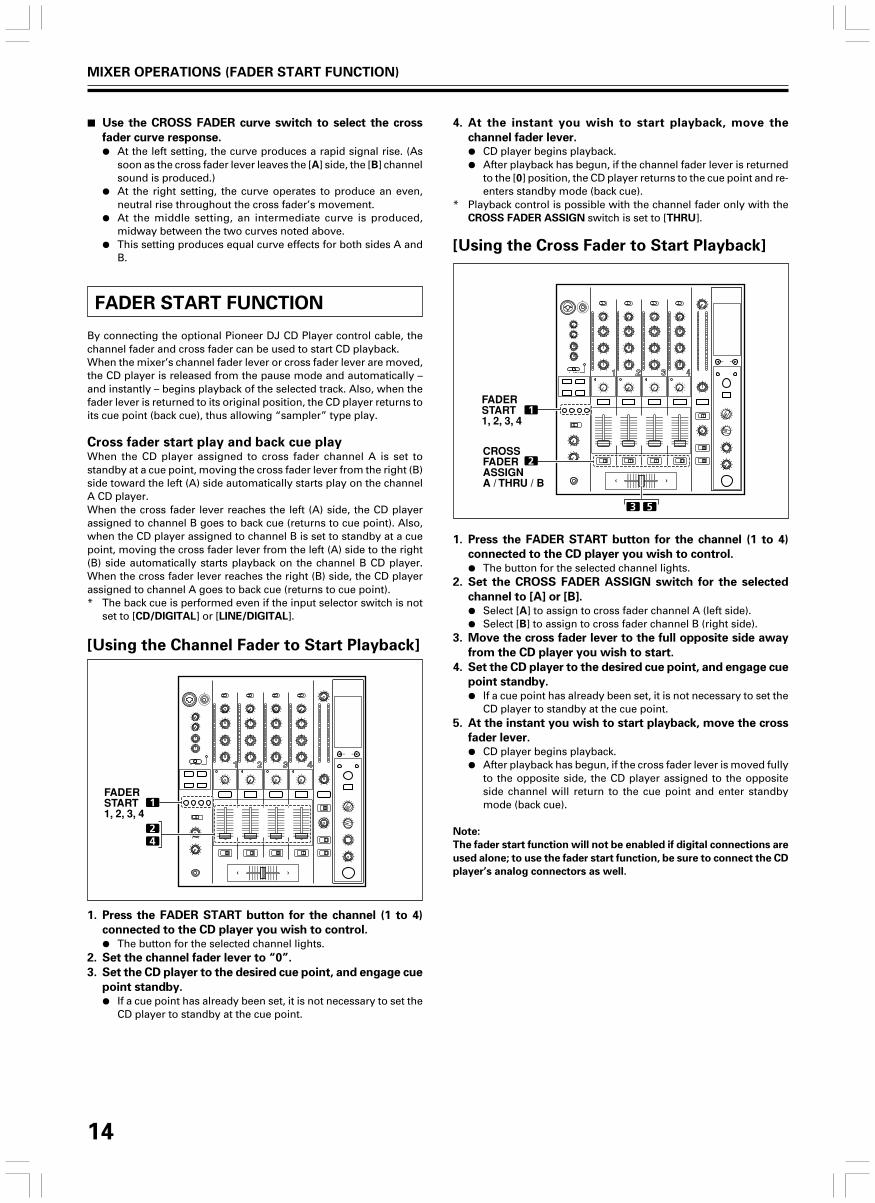
[Using the Channel Fader to Start Playback]
1
24
FADERSTART1, 2, 3, 4
1. Press the FADER START button for the channel (1 to 4)
connected to the CD player you wish to control.
¶ The button for the selected channel lights.2. Set the channel fader lever to “0”.
3. Set the CD player to the desired cue point, and engage cue
point standby.
¶ If a cue point has already been set, it is not necessary to set theCD player to standby at the cue point.
4. At the instant you wish to start playback, move the
channel fader lever.¶ CD player begins playback.¶ After playback has begun, if the channel fader lever is returned
to the [0] position, the CD player returns to the cue point and re-enters standby mode (back cue).
* Playback control is possible with the channel fader only with theCROSS FADER ASSIGN switch is set to [THRU].
[Using the Cross Fader to Start Playback]
1. Press the FADER START button for the channel (1 to 4)
connected to the CD player you wish to control.
¶ The button for the selected channel lights.2. Set the CROSS FADER ASSIGN switch for the selected
channel to [A] or [B].
¶ Select [A] to assign to cross fader channel A (left side).¶ Select [B] to assign to cross fader channel B (right side).
3. Move the cross fader lever to the full opposite side away
from the CD player you wish to start.
4. Set the CD player to the desired cue point, and engage cue
point standby.
¶ If a cue point has already been set, it is not necessary to set theCD player to standby at the cue point.
5. At the instant you wish to start playback, move the cross
fader lever.
¶ CD player begins playback.¶ After playback has begun, if the cross fader lever is moved fully
to the opposite side, the CD player assigned to the oppositeside channel will return to the cue point and enter standbymode (back cue).
Note:
The fader start function will not be enabled if digital connections are
used alone; to use the fader start function, be sure to connect the CD
player’s analog connectors as well.
1
2
3 5
FADERSTART1, 2, 3, 4
CROSSFADERASSIGNA / THRU / B
MIXER OPERATIONS (FADER START FUNCTION)

15
EFFECT FUNCTIONS
This unit can produce beat effects linked to the BPM, and sound-coloreffects linked to the COLOR dials provided for each channel, for atotal of 18 basic effects (including [SND/RTN]). In addition, bychanging the parameters for each kind of effect, an extremely widerange of effect variations can be produced.A wide variety of beat effects can be achieved by varying thetemporal parameter via the TIME dial (Parameter 1), as well asquantitative parameter via the LEVEL/DEPTH dial (Parameter 2).Sound-color effect changes can be added by varying the position ofthe COLOR dials. By combining beat effects and sound-color effects,an even greater range of performance effects can be produced.
TYPES OF BEAT EFFECTS
1. DELAY (One repeat sound)This function allows a delay sound with beat of 1/8, 1/4, 1/2, 3/4,1/1, 2/1, 4/1, 8/1, or 16/1 to be added quickly and simply. Forexample, When a 1/2 beat delay sound is added, four beatsbecome eight beats. Also, by adding a 3/4 beat delay sound,the rhythm becomes syncopated.
Example
Original
(4 beats)
1/2 delay
(8 beats)
3. REVERSE DELAY (One repeat sound)This function allows an inverted delay sound with beat of 1/8,1/4, 1/2, 3/4, 1/1, 2/1, 4/1, 8/1, or 16/1 to be added quickly andsimply.
Example
Original
1/1 reverse
delay
1 beat
1 beat
5. Auto TRANSIn units of 1/16, 1/8, 1/4, 1/2, 1/1, 2/1, 4/1, 8/1, or 16/1 beat, thesound is automatically cut in synch with the rhythm.
Example
1 cycle = 1/16, 1/8, 1/4, 1/2, 1/1, 2/1, 4/1, 8/1,
or 16/1 beat
Cut
Time
Cut
2. ECHO (Multiple repeat sounds)This function allows an echo sound with beat of 1/8, 1/4, 1/2,3/4, 1/1, 2/1, 4/1, 8/1, or 16/1 to be added quickly and simply.For example, when a 1/1 beat echo sound is used to cutoff theinput sound, a sound in synch with the beat is repeated togetherwith fadeout.Also, by adding a 1/1 beat echo to the microphone, themicrophone sound repeats in synch with the music beat.If a 1/1 beat echo is applied to the vocal portion of a track, thesong takes on an effect reminiscent of a “round”.
Example
1 beatCuts input
sound
1 beat
4. Auto PAN (L-R BALANCE)This function distributes sounds in units of 1/16, 1/8, 1/4, 1/2,1/1, 2/1, 4/1, 8/1, or 16/1 to right and left channels in synch withthe rhythm (auto beat pan).Also, short auto pan can be performed, allowing sounds to bedistributed to right/left very quickly, an effect impossible toperform manually.
Example
1 cycle = 1/16, 1/8, 1/4, 1/2, 1/1, 2/1, 4/1, 8/1,
or 16/1 beat
Center
(Stereo)
Auto beat pan
Center
(Stereo)
Short auto pan
EFFECT FUNCTIONS (TYPES OF BEAT EFFECTS)

16
6. FILTERIn units of 1/4, 1/2, 1/1, 2/1, 4/1, 8/1, 16/1, 32/1, or 64/1 beat, thefilter frequency is moved, greatly changing the soundcoloration.
Example
1 cycle = 1/4, 1/2, 1/1, 2/1, 4/1, 8/1,
16/1, 32/1, or 64/1 beat
Frequency
7. FLANGERIn units of 1/4, 1/2, 1/1, 2/1, 4/1, 8/1, 16/1, 32/1, or 64/1 beat, 1cycle of flanger effect is produced quickly and easily.
Example
1 cycle = 1/4, 1/2, 1/1, 2/1, 4/1, 8/1,
16/1, 32/1, or 64/1 beat
Short
delay
8. PHASERIn units of 1/4, 1/2, 1/1, 2/1, 4/1, 8/1, 16/1, 32/1, or 64/1 beat, 1cycle of phaser effect is produced quickly and easily.
Example
1 cycle = 1/4, 1/2, 1/1, 2/1, 4/1, 8/1,
16/1, 32/1, or 64/1 beat
Phase shift
9. REVERBProduces reverberation effect.
10. ROBOTInput sounds are reproduced as though generated by a robot.
11. CHORUSGenerates a chorus sound in synch with 1/8, 1/4, 1/2, 1/1, 2/1,4/1, 8/1, or 16/1 beat. The sound produced has breadth asthough the same pitch were issuing from multiple sources.
12. ROLLSounds of 1/16, 1/8, 1/4, 1/2, 1/1, 2/1, 4/1, 8/1, or 16/1 beat arerecorded and output repetitively. Also, when sounds arechanged from 1/1 beat to 1/2 or 1/4 in synch with the beat, a rollsound effect can be produced.
Example
Repeat
Original
1/1 roll
Effect ON
13. REVERSE ROLLSounds of 1/16, 1/8, 1/4, 1/2, 1/1, 2/1, 4/1, 8/1, or 16/1 beat arerecorded, inverted, and output repetitively. Also, when soundsare changed from 1/1 beat to 1/2 or 1/4 in synch with the beat,an inverted playback roll sound effect can be produced.
Example
Reversed repeat
Original
1/1 reverse roll
Effect ON
14. SEND/RETURNBy connecting a sampler or effector, a wide variety of othereffects can be created.
EFFECT FUNCTIONS (TYPES OF BEAT EFFECTS)

17
PRODUCING BEAT EFFECTS
EFFECT SELECT
CH SELECT
PARAMETER
1 2 3 4
MIC MST
AUTO MIDITAP BPM
%
A B
1
4
2
3
5
TAPAUTO/TAP
ON/OFF
TIME
LEVEL/DEPTH
BEAT 2, 3
Display example
Effect Name: DELAY
Effect Channel Select: CH 1
BPM value: 120 BPM
Parameter 1: 500 ms
Beat multiple: 1/1
Beat effects allow the instant setting of effect times in synch with theBPM (beats per minute), thus allowing the production of a widevariety of effects in synch with the current rhythm, even during liveperformances.
1. Press the AUTO/TAP button to set the Beats Per Minute
(BPM = track speed) measuring mode.
AUTO:The BPM of the input music signal is detected automatically.TAP: The BPM is input manually by tapping on the TAP button.¶ Whenever power is first turned ON, the function defaults to the
[AUTO] mode.¶ The indicator for the selected mode [AUTO/TAP] lights in the
display.¶ In the event the track’s BPM cannot be detected automatically,
the display’s BPM counter will flash.¶ The effective range in the AUTO mode is 70 to 180 BPM.
It may not be possible to measure some tracks accurately.
In this case, use the TAP mode for manual BPM input.
[Using the TAP Button for Manual BPM Input]If the TAP button is tapped two times or more in synch
with beat (1/4 notes), the BPM will be recorded as the
average value recorded during that interval.¶ When BPM mode is set to [AUTO], tapping the TAP button
will cause the BPM mode to change to the TAP mode, andthe interval at which the TAP button is pressed will bemeasured.
¶ When the BPM is set via the TAP button, the beat multiplebecomes “1/1” (or “4/1”, depending on the effect selected),and the time for 1 beat (1/4 notes) or 4 beats will be set asthe effect time.
¶ If the TIME dial is rotated while depressing the TAP button,direct BPM can be set manually.If the TIME dial is rotated while holding the TAP button andAUTO/TAP buttons depressed, the BPM can be set in 0.1units.
2. Set the effect selector to the desired effect.
¶ The display will show the name of the selected effect.¶ See P. 15 to 16 for details regarding the various effects.
3. Set the effect channel selector to the channel you wish to
apply the effect to.¶ The display’s channel name indicator will show the selected
channel with red frame.¶ If [MIC] is selected, the effect will be applied to both
microphone 1 and microphone 2.4. Press the BEAT button (2, 3) to select the beat multiple to
which the effect is to be synchronized.
¶ When 3 is pressed, the beat count calculated from the BPM isdoubled, and when 2 is pressed, the beat count calculatedfrom the BPM is halved (some effects also allow “3/4” setting).
¶ The multiple of the selected beat (parameter 1 position) isdisplayed in seven sections on the display (see P. 12).
¶ The effect time corresponding to the beat’s multiple is setautomatically.Example: When BPM = 1201/1 = 500 ms1/2 = 250 ms2/1 = 1 000 ms
5. Set the ON/OFF button to ON to enable the effect.
¶ Each time the button is pressed, the effect alternates ON/OFF(whenever power is first turned ON, the function defaults toOFF).
¶ The ON/OFF button flashes when the effect is ON.
Parameter 1Rotating the TIME (PARAMETER 1) dial adjusts the temporalparameter (time) for the selected effect.See P. 19 for details regarding the effect on parameter 1 of rotatingthe TIME (PARAMETER 1) dial.
Parameter 2Rotating the LEVEL/DEPTH (PARAMETER 2) dial adjusts thequantitative parameter for the selected effect.See P. 19 for details regarding the effect on parameter 2 of rotatingthe LEVEL/DEPTH (PARAMETER 2) dial.
EFFECT FUNCTIONS (PRODUCING BEAT EFFECTS)

18
TYPE OF SOUND-COLOR EFFECT
1. HARMONICDetects deviation of the input sound from absolute pitch andautomatically compensates to the nearest key.By rotating the dial, the pitch/key can be adjusted within arange of ±6 half-tones.
COLOR
HILOW
Input sound
3. CRUSHThis effect slightly “crushes” the sound, applying a certainaccent to the sound.
4. FILTERThe filter frequency is shifted, resulting in strong changes tothe tone.Rotating the dial to the right produces high-pass filter effects,while rotating the dial to the left produces low-pass filtereffects.
Low-pass filter
Frequency
COLOR
HILOW
High-pass filter
Frequency
USING SOUND-COLOR EFFECTS
Sound-color effects are linked to the COLOR effect parameter dial foreach channel.* Sound-color effects are not applied to microphone inputs.
1. Press the sound-color effect selector buttons (HARMONIC,
SWEEP, FILTER, CRUSH) for the desired effect.
HARMONIC:
Applies a pitch-shifted effect matching the track’s key.SWEEP:
The track is passed through the filter and output.CRUSH:
The track’s sound is output in a “crush” effect.FILTER:
The track is filtered and output.¶ The button for the selected effect will flash.¶ The selected effect is applied equally to channels 1 to 4.¶ If the flashing button is pressed, it lights steadily, and the effect
turns OFF.¶ When power is first turned on, all effects default to OFF
(indicators are lighted).
2. Use the sound-color effect parameter dial (COLOR) to
adjust the quantitative parameter for the effect.
¶ The parameter can be adjusted independently for eachchannel.
¶ The color of the harmonic indicator changes to indicate thecondition of the harmonic effect.Red: Does not match frequency of key scale.Green: Matches frequency of key scale.
1HARMONIC,
SWEEP,FILTER,CRUSH
2 COLOR
EFFECT FUNCTIONS (TYPE OF SOUND-COLOR EFFECT/USING SOUND-COLOR EFFECTS)
Compensated sound
Notch filter Band pass filter
Frequency Frequency
2. SWEEPThis function shifts the frequence of the filter, producing largechanges in tone. When the dial is rotated clockwise, the effectproduced is that of a band-pass filter, while rotating the dialcounterclockwise produces the effect of a notch filter.
COLOR
HI1 kHz LOW 1 kHz

19
EFFECT PARAMETERS
Beat Effect
Sound-color effects
Name
1 HARMONIC
2 SWEEP
3 CRUSH
4 FILTER
Parameter (COLOR dial)
Sets amount of pitch shift in range of ±6 half-tones. Rotating dialto right increases pitch shift by +6 half-tones, while rotating to theleft reduces pitch shift by –6 half-tones.
Sets filter's cutoff frequency. Rotating dial clockwise producesband-pass filter effect; rotating counterclockwise produces notchfilter effect.
Sets amount of crushing of input sound. Rotate dialcounterclockwise to emphasize low-range sounds, and rotateclockwise to emphasize high-range sounds.
Sets cutoff frequency of filter. Rotating dial to right changes high-pass filter; rotating dial to left changes low-pass filter.
Name
1 DELAY
2 ECHO (*1)
3 REVERSE DELAY
4 PAN
5 TRANS
6 FILTER
7 FLANGER
8 PHASER
9 REVERB (*1)
10 ROBOT
11 CHORUS
12 ROLL (*2)
13 REVERSE ROLL (*2)
14 SEND/RETURN
Beat Switch Parameter
Sets delay time of 1/8 to 16/1 per 1beat of BPM time.
Sets delay time of 1/8 to 16/1 per 1beat of BPM time.
Sets delay time of 1/8 to 16/1 per 1beat of BPM time.
Sets time of 1/16 to 16/1 per 1 beat ofBPM time for distribution to right/left.
Sets cut time of 1/16 to 16/1 per 1beat of BPM time.
Cycle of cutoff frequency shift is setin unit of 1/4 to 64/1 relative to 1beat of BPM.
Cycle of flanger shift is set in unitsof 1/4 to 64/1 relative to 1 beat ofBPM.
Cycle of phaser effect shift is set inunits of 1/4 to 64/1 relative to 1 beatof BPM.
Amount of reverberation is set from1 to 100 %.
Sets pitch of robot sound effectwithin range of –100 to +100 %.
Cycle of chorus sound waver is setin units of 1/4 to 64/1 relative to 1beat of BPM.
Effect time is set as 1/16 to 16/1relative of 1 beat of BPM.
Effect time is set as 1/16 to 16/1relative of 1 beat of BPM.
—
Contents
Sets delay time.
Sets delay time.
Sets delay time.
Sets effect time.
Sets effect time.
Sets cycle forcutoff time shift.
Sets cycle forflanger effectshift.
Sets cycle forphase effect shift.
Sets amount ofreverberationeffect.
Sets pitch ofrobot soundeffect.
Sets cycle ofchorus soundharmonic.
Sets effect time.
Sets effect time.
—
Setting Range (unit)
1 to 4 000 (ms)
1 to 4 000 (ms)
10 to 4 000 (ms)
10 to 16 000 (ms)
10 to 16 000 (ms)
10 to 32 000 (ms)
10 to 32 000 (ms)
10 to 32 000 (ms)
1 to 100 (%)
–100 to +100 (%)
10 to 32 000 (ms)
1 to 4 000 (ms)
1 to 4 000 (ms)
—
Parameter 2
(MIX/DEPTH dial) contents
Sets balance between original anddelay sound.
Sets balance between originalsound and echo sound.
Sets balance between original anddelay sound.
Sets balance between originalsound and effect sound.
Sets balance between originalsound and effect sound.
Amount of effect increases whendial is turned clockwise.
Amount of effect increases whendial is turned clockwise. When dialis turned fully counterclockwise,only original sound is output.
Amount of effect increases whendial is turned clockwise. When dialis turned fully counterclockwise,only original sound is output.
Sets balance between originalsound and effect sound.
Amount of effect increases whendial is turned clockwise.
Sets balance of chorus sound.
Sets balance of original sound androll sound.
Sets balance of original sound androll sound.
Sets volume of RETURN inputsound.
Parameter 1 (TIME dial)
EFFECT FUNCTIONS (EFFECT PARAMETERS)
(*1) Even if the effect monitor is turned ON, if no sound is output from the channel to the master output, the effect sound will not be heard.(*2) When effect is disabled (OFF), the effect sound will not be heard, even if monitor is set to effector.

20
MIDI SETTINGS
MIDI is an acronym for “Musical Instrument Digital Interface” andrefers to a protocol developed for the exchange of data betweenelectronic instruments and computers.A MIDI cable is used to connect components equipped with MIDIconnectors to enable the transmission and receipt of data.The DJM-800 uses the MIDI protocol for transmitting and receivingdata about component operation and BPM (timing clock).
MIDI START/STOP
TIME
MIDI OUT
DJM-800
OUT
BPM=120
BPM=120
IN
IN
DJ CD Player
MIDI sequencer
Audio
1. Use a commercially available MIDI cable to connect the
DJM-800’s MIDI OUT connector to the MIDI sequencer’s
MIDI IN connector.
¶ Set the MIDI sequencer’s synch mode to “Slave”.¶ MIDI sequencers that do not support MIDI timing clock cannot
be synchronized.¶ Synch may not be achieved if the track’s BPM cannot be
detected and measured stably.¶ BPM values set with the TAP mode can also be used to output
the timing clock.2. Press the MIDI START/STOP button.
¶ The MIDI timing clock output range is 40 to 250 BPM.Note:
¶ Accurate measuring of BPM may be impossible with some tracks.
[MIDI Channel Setting]The MIDI channel (1 to 16) can be set and stored in memory.1. While holding the MIDI START/STOP button depressed,
set the power switch to ON.
¶ The display will show [MIDI CH SETTING] and the unit willenter the MIDI setting mode.
2. Rotate the TIME dial to select the MIDI channel.
3. Press the MIDI START/STOP button.
¶ The selected MIDI channel will be recorded.4. Set power to OFF.
MIDI MESSAGES
CH1
CH2
CH3
TRIM
HI
MID
LOW
COLOR
CUE
FADER
CF ASSIGN
TRIM
HI
MID
LOW
COLOR
CUE
FADER
CF ASSIGN
TRIM
HI
MID
LOW
COLOR
CUE
FADER
CF ASSIGN
VR
VR
VR
VR
VR
BUTTON
VR
SW
VR
VR
VR
VR
VR
BUTTON
VR
SW
VR
VR
VR
VR
VR
BUTTON
VR
SW
Bn 01 dd
Bn 02 dd
Bn 03 dd
Bn 04 dd
Bn 05 dd
Bn 46 dd
Bn 11 dd
Bn 41 dd
Bn 06 dd
Bn 07 dd
Bn 08 dd
Bn 09 dd
Bn 0A dd
Bn 47 dd
Bn 12 dd
Bn 42 dd
Bn 0C dd
Bn 0E dd
Bn 0F dd
Bn 15 dd
Bn 16 dd
Bn 48 dd
Bn 13 dd
Bn 43 dd
0 to 127
0 to 127
0 to 127
0 to 127
0 to 127
OFF=0, ON=127
0 to 127
0, 64, 127
0 to 127
0 to 127
0 to 127
0 to 127
0 to 127
OFF=0, ON=127
0 to 127
0, 64, 127
0 to 127
0 to 127
0 to 127
0 to 127
0 to 127
OFF=0, ON=127
0 to 127
0, 64, 127
Category Switch Name Switch TypeMIDI Message
CommentsMSB LSB
MIDI SETTINGS
SYNCHRONIZING AUDIO SIGNALSTO EXTERNAL SEQUENCER, ORUSING DJM-800 INFORMATION TOOPERATE AN EXTERNALSEQUENCER

21
MIDI SETTINGS
PROGRAM CHANGE
SNAPSHOT
Once the DJM-800 is setup with parameters for a given purpose, thatset of parameters can be recorded as a snapshot. When snapshot ofthe current status is recorded, all messages for control change andprogram change are transmitted. Hold the MIDI START/STOP buttondepressed to send the snapshot.
MSB LSB0 0 EFFSEL2 EFFSEL1 EFFSEL0 EFFCH2 EFFCH1 EFFCH0
EFFSEL2 EFFSEL1 EFFSEL00 0 1 DELAY0 1 0 ECHO— — — REV DELAY0 1 1 PAN1 0 0 TRANS1 0 1 FILTER1 1 0 FLANGER1 1 1 PHASER— — — REVERB— — — ROBOT— — — CHORUS— — — ROLL— — — REV ROLL— — — SND/RTN
• EFFECT SEL BEAT
EFFCH2 EFFCH1 EFFCH00 0 1 10 1 0 20 1 1 31 0 0 41 0 1 MIC1 1 0 CF.A1 1 1 CF.B— — — MST
• EFFECT SEL
Category Switch Name Switch TypeMIDI Message
CommentsMSB LSB
CH4
CROSS FADER
FADER CURVE
MASTER
BOOTH
EFFECT
MIC
(SOUND COLOR
FX)
(FADER START)
(HEAD PHONES)
MIDI
TRIM
HI
MID
LOW
COLOR
CUE
FADER
CF ASSIGN
CROSS FADER
CH CURVE
CROSS CURVE
MASTER LEVEL
BALANCE
CUE
MONITOR
BEAT LEFT
BEAT RIGHT
AUTO/TAP
TAP
CUE
EFFECT SELECT
CH SELECT
TIME
LEVEL/DEPTH
EFFECT ON/OFF
HI
LOW
HARMONIC
SWEEP
CRUSH
FILTER
1
2
3
4
MIXING
LEVEL
START
STOP
VR
VR
VR
VR
VR
BUTTON
VR
SW
VR
SW
SW
VR
VR
BUTTON
VR
BUTTON
BUTTON
BUTTON
BUTTON
BUTTON
SW
SW
SW
VR
BUTTON
VR
VR
BUTTON
BUTTON
BUTTON
BUTTON
BUTTON
BUTTON
BUTTON
BUTTON
VR
VR
BUTTON
BUTTON
Bn 50 dd
Bn 51 dd
Bn 5C dd
Bn 52 dd
Bn 53 dd
Bn 49 dd
Bn 14 dd
Bn 44 dd
Bn 0B dd
Bn 5E dd
Bn 5F dd
Bn 18 dd
Bn 17 dd
Bn 4A dd
Bn 19 dd
Bn 4C dd
Bn 4D dd
Bn 45 dd
Bn 4E dd
Bn 4B dd
Cn pc
Cn pc
Bn 0D MSB Bn 2D LSB
Bn 5B dd
Bn 40 dd
Bn 1E dd
Bn 1F dd
Bn 54 dd
Bn 55 dd
Bn 56 dd
Bn 57 dd
Bn 58 dd
Bn 59 dd
Bn 5A dd
Bn 5D dd
Bn 1B dd
Bn 1A dd
FA
FC
0 to 127
0 to 127
0 to 127
0 to 127
0 to 127
OFF=0, ON=127
0 to 127
0, 64, 127
0 to 127
0, 64, 127
0, 64, 127
0 to 127
0 to 127
OFF=0, ON=127
0 to 127
OFF=0, ON=127
OFF=0, ON=127
OFF=0, ON=127
OFF=0, ON=127
OFF=0, ON=127
See “PROGRAM CHANGE”below.
0 to 127
OFF=0, ON=127
0 to 127
0 to 127
OFF=0, ON=127
OFF=0, ON=127
OFF=0, ON=127
OFF=0, ON=127
OFF=0, ON=127
OFF=0, ON=127
OFF=0, ON=127
OFF=0, ON=127
0 to 127
0 to 127
TIME value; FLANGER, PHASER,CHORUS, FILTER changed to 1/2value; minus values areconverted to positive.

22
TROUBLESHOOTING
Incorrect operations are often mistaken for trouble and malfunctions. If you think there is something wrong with this component, checkthe points below. Sometimes the trouble may originate from another component. Thus, also check the other electrical appliances also inuse.If the trouble cannot be rectified even after checking the following items, contact your dealer or nearest PIONEER service center.
Static electricity or other external interference may cause the unit to malfunction. To restore normal operation, turn the power off and thenon again.
Symptom
No power
No sound, or sound volume is toolow.
Microphone sound isn’t produced inBOOTH output.
No digital output.
Sound is distorted.
Cross fader doesn’t work.
Can’t perform fader start with CDplayer.
Effects don’t work.
External effector doesn’t work.
Sound from external effector isdistorted.
BPM can’t be measured.Measured BPM value is incorrect.
The measured BPM value isdifferent from the value publishedwith the CD.
MIDI sequencer can’t besynchronized.
Possible Cause
÷ The power cord has not been connected.
÷ Input selector is set incorrectly.÷ The rear panel’s DIGITAL/CD input selector
switch or DIGITAL/LINE input selectorswitch is set incorrectly.
÷ Connection cables are connectedincorrectly, or connections are loose.
÷ Jacks or plugs are dirty.÷ The rear panel master output attenuator
switch (MASTER ATT) is set to –12 dB, etc.
÷ The rear panel’s MIC SIGNAL switch is setto [CUT].
÷ The digital output sampling frequency (fs)does not match the specifications of theconnected component.
÷ Master output level is too high.
÷ Input level is too high.
÷ CROSS FADER ASSIGN switch setting ([A],[THRU], [B]) is incorrect.
÷ The FADER START button is set to OFF.÷ Rear panel CONTROL jack is not connected
to CD player.÷ Only the rear panel CONTROL jack is
connected to the CD player.
÷ Effect channel selecter setting is incorrect.
÷ Effect parameter 2 adjust dial (LEVEL/DEPTH) is set to [MIN].
÷ Effect selecter is not set to [SND/RTN].÷ Effector is not connected to rear panel
SEND/RETURN connector.÷ Effect channel selector is set to incorrectly.
÷ Input level from external effector is set toohigh.
÷ Input level is too high, or too low.
÷ BPM may not be correctly measurable withsome tracks.
÷ Some differences may occur due todifferences in BPM detection methods.
÷ MIDI sequencer’s synch mode is not set to“slave”.
÷ MIDI sequencer is not supported type.
Remedy
÷ Connect to power outlet.
÷ Set input selector to playback component.÷ Set the rear panel’s DIGITAL/CD input selector
switch or DIGITAL/LINE input selector switchto match the component being played.
÷ Connect correctly.
÷ Clean soiled jacks/plugs before connecting.÷ Adjust rear panel master attenuator switch
(MASTER ATT).
÷ Set rear panel’s MIC SIGNAL switch to [ADD].
÷ Set rear panel sampling frequency selector tomatch the specifications of the connectedcomponent.
÷ Adjust master output level (MASTER LEVEL)dial or the rear panel master output attenuator(MASTER ATT) switch.
÷ Adjust the TRIM dial so that the input levelapproaches 0 dB on the channel levelindicator.
÷ Correctly set the CROSS FADER ASSIGNswitch for the desired channel.
÷ Set the FADER START button to ON.÷ Use a control cable to connect the CONTROL
jacks of mixer and CD player.÷ Connect both the CONTROL jacks and analog
input connectors.
÷ Correctly select the channel on which youwish to apply effects.
÷ Adjust the effect parameter 2 adjust dial(LEVEL/DEPTH).
÷ Set effect selector to [SND/RTN].÷ Connect effector to the rear panel SEND/
RETURN connectors.÷ Use the effect channel selector to select the
audio source to which you wish to apply theeffects.
÷ Lower the output level of the external effector.
÷ Adjust the TRIM dial so that the input levelapproaches 0 dB in the channel level indicator.
÷ Adjust other channels as well so that the inputlevels approach 0 dB in the channel levelindicator.
÷ Strike the TAP button to set BPM manually.
÷ No remedy is necessary.
÷ Set MIDI sequencer’s sync mode to “slave”.
÷ MIDI sequencers that do not support MIDItiming lock cannot be synchronized.
TROUBLESHOOTING

23
SPECIFICATIONS
1. GeneralPower source .............................................................. AC 120 V, 60 HzPower consumption ..................................................................... 32 WOperating temperature ..................... +5 ˚C to +35 ˚C (+41 ˚F to +95 ˚F)Operating humidity .................... 5 % to 85 % (without condensation)Weight .......................................................................... 7.5 kg (16.54 lb)Maximum dimensions ...................... 320 (W) × 381 (D) × 108 (H) mm
12-5/8 (W) × 15 (D) × 4-1/4 (H) in
2. Audio sectionSampling rate ............................................................................. 96 kHzA/D, D/A converter ...................................................................... 24 bitsFrequency response
LINE ......................................................................... 20 Hz to 20 kHzMIC .......................................................................... 20 Hz to 20 kHzPHONO ......................................................... 20 Hz to 20 kHz (RIAA)
S/N ratio (at rated output)LINE ....................................................................................... 104 dBPHONO .................................................................................... 88 dBMIC .......................................................................................... 84 dB
Distortion (LINE-MASTER 1) .................................................... 0.005 %Standard input level/Input impedance
PHONO 2 to 4 ............................................................ –52 dBu/47 kΩMIC 1, MIC 2 ............................................................... –52 dBu/3 kΩLINE, LINE/CD 1 to 4 ................................................. –12 dBu/22 kΩRETURN .................................................................... –12 dBu/22 kΩ
Standard output level/Load impedance/Output impedanceMASTER 1 .............................................. +2 dBu/600 Ω/10 Ω or lessMASTER 2 .......................................................... +2 dBu/10 kΩ/1 kΩREC ..................................................................... –8 dBu/10 kΩ/1 kΩBOOTH ............................................................. +2 dBu/600 Ω/600 ΩSEND ................................................................ –12 dBu/10 kΩ/1 kΩPHONES ................................................ +8.5 dBu/32 Ω/22 Ω or less
Rated output level/Load impedanceMASTER 1 ................................................................ +22 dBu/600 ΩMASTER 2 .................................................................+20 dBu/10 kΩ
Crosstalk (LINE) ............................................................................ 88 dBChannel equalizer response
HI ............................................................... –26 dB to +6 dB (13 kHz)MID ............................................................. –26 dB to +6 dB (1 kHz)LOW ............................................................ –26 dB to +6 dB (70 Hz)
Microphone equalizer responseHI ............................................................... –12 dB to +6 dB (10 kHz)LOW .......................................................... –12 dB to +6 dB (100 Hz)
3. Input/output connector systemsPHONO input connectors
RCA pin jacks ..................................................................................3LINE/CD input connectors
RCA pin jacks ..................................................................................4LINE input connectors
RCA pin jacks ..................................................................................1MIC input connectors
XLR connector/phone jack (Ø6.3 mm) ........................................... 1Phone jack (Ø6.3 mm) .................................................................... 1
DIGITAL coaxial input connectorsRCA pin jacks ..................................................................................4
RETURN input connectorsPhone jacks (Ø6.3 mm) .................................................................. 1
MASTER output connectorsXLR connectors ...............................................................................1RCA pin jacks ..................................................................................1
BOOTH output connectorsPhone jacks (Ø6.3 mm) .................................................................. 1
REC output connectorsRCA pin jacks ..................................................................................1
SEND output connectorsPhone jacks (Ø6.3 mm) .................................................................. 1
DIGITAL coaxial output connectorRCA pin jack ....................................................................................1
MIDI OUT connector5P DIN..............................................................................................1
PHONES output connectorStereo phone jack (Ø6.3 mm) ........................................................1
CONTROL connectorMini phone jacks (Ø3.5 mm) ..........................................................4
4. AccessoriesOperating Instructions .........................................................................1Power cord ........................................................................................... 1Warranty card ......................................................................................1
Specifications and appearance are subject to change without notice.
300 Allstate Parkway
Markham, ON L3R OP2
(905) 479-4411
1 (877) 283-5901
For warranty information please see the Limited Warrantysheet included with your product.
Should this product require service in Canada, please contact aPioneer Canadian Authorized Dealer to locate the nearest Pio-neer Authorized Service Company in Canada.Alternatively, please contact the Customer Service Departmentat the following address:
Pioneer Electronics of Canada, Inc.
Should this product require service in the U.S.A. and you wishto locate the nearest Pioneer Authorized Independent ServiceCompany, or if you wish to purchase replacement parts,operating instructions, service manuals, or accessories, pleasecall the number shown below.
800 – 782 – 7210Please do not ship your product to Pioneer without first callingthe Customer Support Division at the above listed number forassistance.PIONEER ELECTRONICS (USA), INC.
CUSTOMER SUPPORT DIVISION
P.O. BOX 1760, LONG BEACH,
CA 90801-1760, U.S.A.
For warranty information please see the Limited Warrantysheet included with your product.
SPECIFICATIONS

24
Published by Pioneer Corporation.Copyright © 2005 Pioneer Corporation.All rights reserved.
PIONEER CORPORATION 4-1, Meguro 1-Chome, Meguro-ku, Tokyo 153-8654, Japan
PIONEER ELECTRONICS (USA) INC.Multimedia and Mass Storage Division: 2265 East 220th Street, Long Beach, CA 90810, U.S.A. TEL: 800-444-OPTI (6784)PIONEER ELECTRONICS OF CANADA, INC.Industrial Products Department: 300 Allstate Parkway, Markham, Ontario L3R OP2, Canada TEL: 905-479-4411
Printed in <DRB1393-A><05L00000>
BLOCK DIAGRAM
MIC AMP
MIC 1
MIC 2
PHONES
MASTER 1
MASTER 2
DIGITAL OUT
BOOTH
REC
SEND
RETURN
MIC 1 LEVEL
MIC AMP
BUFFER
BUFFER
LINE
CDDIGITAL
CD
MIC 2 LEVEL
MIC
LINE
CD
DIGITAL
CH 1
DIR SRC
BUFFERTRIM
VR ADPHONO/LINE SW. DIGITAL SEL.DIGITAL/ANALOG SW.
-COM
A/D
D/A
D/A
A/D
DSP
DSP
DIGI
TAL/C
D
SW.
CD/DIGITALLINE SW.
CD/DIGITALCD
DIGITALCD
DIGITAL
LINELINELINE
PHONO AMP.
BUFFER
PHONO
CDDIGITAL
CD
PHONO
CD
DIGITAL
CH 2
MIC 1MIC 2
CH 1
MASTER ATT.
BUFFER AMP.
MUTE
MUTE
MUTE
MUTE
MUTE
MUTE
AMP.
AMP.
BUFFER
BUFFER
CH 2
RETURN
SEND
REC
BOOTH
MASTER
PHONES
CH 3
CH 4
DIR SRC
BUFFERTRIM
VR ADPHONO/LINE SW. DIGITAL SEL.DIGITAL/ANALOG SW.
-COM
A/D
CH 4 same as CH 3
DIGI
TAL/C
D
SW.
CD/DIGITALPHONO SW.
CD/DIGITALCD
DIGITALCD
DIGITAL
PHONOPHONOPHONO
PHONO AMP.
BUFFER
PHONO
ANALOGDIGITAL
LINE/CD
PHONO
LINE
DIGITAL
CH 3
DIR SRC
BUFFERTRIM
VR ADPHONO/LINE SW. DIGITAL SEL.DIGITAL/ANALOG SW.
-COM
A/D
DIGI
TAL/L
INE
S
W.
LINE/DIGITALPHONO SW.
LINE/DIGITALLINE
DIGITALLINE
DIGITAL
PHONOPHONOPHONO
D/A
D/A
A/D
-COMFPGA
SDRAM FLASHROM
SRC DIT
D/A
Digital Trim CHn FaderMasterBalance Talk Over
H. P. Level
Booth Level
Master Level
CF assign
CHxBPM
detectCHx
3-BandCHnEQ
2-BandMIC EQ
MIC 1,2MIX
COLOREFFECTS[ch1–4] BEAT
EFFECTS[CF_A(pre)]
BEATEFFECTS[CF_A(post)]
SendReturn[CF_A]
BEATEFFECTS[CHx(pre)]
SendReturn[CHx]
BEATEFFECTS
[MIC]
BEATEFFECTS[SND/RTN]
SendReturn[MIC]
MasterBalance
BEATEFFECTS[CHx(post)] BPM
detect[CF_A]
BEATEFFECTS[Master]
SendReturn
[Master]
BPMdetect
[Master]
H. P.MIX
MasterMono Stereo
THRUCF_ACF_B
(3-posi.)
CUEMonitor[CHx]
BPMdetect[MIC]
MICLow-cut
Filter
CHFaderCurve
(3-posi.)
CROSSFader
CROSSFaderCurve
(3-posi.)
MIC Data
CHx CUECUE Balance
Master Balance
Mono SplitStereo
RL
RL
EFFECT CUE
Master CUE
CH 1– 4 In
BPM Counter
Cable Check
Talk Over On/Off
Talk Over On/OffCHx Level Meter
Master Level Meter
Master Out 1
Rec Out
CHn in
MIC 1, 2 in
Return In
Send Out
Digital in
Analog in
Master Out 2
Digital Out
H. P. Out
H. P. Out Lch
H. P. Out RchReturn In
Booth Out
MIC SWOFFON
Talk Over(3-posi.)
CH 1–4CF_A/BMICMaster
CHxBEAT
EFFECTS[CF_B(pre)]
SendReturn[CF_B]
BPMdetect[CF_B]
BEATEFFECTS[CF_B(post)]
CH1–CH4 COMMON
MIC Data
MIC Data
CHx CUE
CHx MIX Data
Effect CUE
Master CUE
Bus
EFFECT CH SELECT
• Mode• Volume data• Switch data• CH Fader position• CF Fader position• Control Command
CPUI/F
Logic
FPGA[Dual Port RAM]
• DSP Status• BPM Detect data• Harmonic Detect data• CH Level Meter• Master Level Meter
CPUI/F
Logic
EFFECT Processor
FPGA[Dual PortRAM]
SD-RAM
Send to CPU
Send to CPU
Effect Control (from CPU)
CH 1–4CF_A/BMICMaster
EFFECT CH SELECT
CH 1–4CF_A/BMICMaster
EFFECT CH SELECT
H. P. Level
H. P. Level
H. P. MONO SPLIT/STEREO SW.
Return Level No Cable Effect SW.
Cable Exit
Mono SplitStereo
H. P. MIX
COLOR EFFECT (HARMONIC)
BPM DET.
BEAT EFFECT (SND/RTN)
Effect OutEFFECT CUE
Send Out
CH 1–4CF_A/BMICMaster
EFFECT CH SELECTEffect SW.
BEAT EFFECT (Others)
Effect OutMIX RatioEFFECT CUE
Effect ProcessorEffect Processor
Freqency Counter
CH 1– 4 Out Effect Control (from CPU)
CH 1– 4 In
COLOR EFFECT (Others)
Effect Processor CH 1– 4 Out
BLOCK DIAGRAM