Embed Size (px)
Citation preview
Drawing Orienteering Maps in OCAD 12
Copyright © 1988 – 2017 OCAD AG www.ocad.com

Draw Orienteering Maps in OCAD
Copyright © 1988 – 2017 OCAD AG Page 2
About this Document This document is produced for an OCAD course. It is a complement to Getting Started with OCAD 12, that is delivered as a PDF file with OCAD software. The focus of this document is straighten on the function of OCAD to draw an orienteering map. Suggestions and complements are welcomed at all times: [email protected] . Baar, February 2017
OCAD® is a registered trademark of OCAD AG.
OCAD AG Mühlegasse 36
CH - 6340 Baar / Switzerland Tel (+41) 41 763 18 60
Fax (+41) 41 763 18 64
[email protected] http://www.ocad.com
Draw Orienteering Maps in OCAD
Copyright © 1988 – 2017 OCAD AG Page 3
Table of Contents 1 About OCAD ............................................................................................................................................ 4
1.1 OCAD User Interface ........................................................................................................................ 4 1.2 OCAD Help, Learn Videos and Getting Started ........................................................................... 5 1.3 Service Update .................................................................................................................................. 5
2 New Map ................................................................................................................................................. 6 2.1 Start a New Map File ......................................................................................................................... 6 2.2 Set a Map ........................................................................................................................................... 6 2.3 Georeferencing ................................................................................................................................. 7
3 Create the Base Map for the Field Work ............................................................................................... 8 3.1 Raster Base Map ............................................................................................................................... 8 3.2 Preparation of Airborne Laserscanning Data ................................................................................ 9 3.3 Import Vector Data ......................................................................................................................... 12 3.4 Revision of an Existing Orienteering Map ..................................................................................... 13
4 Prepare your field work for digitizing ................................................................................................... 14 4.1 Scan Field Work, Open it as a Background Map and Adjust .................................................... 14 4.2 Background Map Options ............................................................................................................. 14 4.3 Hide Background Maps .................................................................................................................. 15
5 Draw an Object on the Map ................................................................................................................ 16 5.1 Drawing Generally .......................................................................................................................... 16 5.2 Draw a Point Object ....................................................................................................................... 16 5.3 Draw a Line and Area Object ....................................................................................................... 17
6 Edit Objects............................................................................................................................................ 22 6.1 General Editing ................................................................................................................................ 22 6.2 Remove, Move, Reshape, Change the Symbol ......................................................................... 22 6.3 Edit Line Objects .............................................................................................................................. 24 6.4 Edit Area Objects ............................................................................................................................ 25
7 Colors and Symbols .............................................................................................................................. 26 7.1 Colors ................................................................................................................................................ 26 7.2 Symbols ............................................................................................................................................. 26
8 Print and Export ..................................................................................................................................... 27 8.1 Print Map .......................................................................................................................................... 27 8.2 Export Map as PDF .......................................................................................................................... 28 8.3 Export Encrypted OCAD Files ........................................................................................................ 29
9 Options ................................................................................................................................................... 30 9.1 OCAD Preferences ......................................................................................................................... 30 9.2 Shortcuts ........................................................................................................................................... 30 9.3 Language......................................................................................................................................... 30
10 Excursion ................................................................................................................................................ 31 10.1 Symbol Status Manager ................................................................................................................. 31
Draw Orienteering Maps in OCAD
Copyright © 1988 – 2017 OCAD AG Page 4
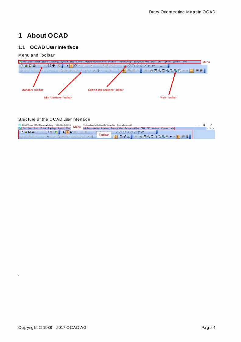
1 About OCAD 1.1 OCAD User Interface Menu and Toolbar
Structure of the OCAD User Interface
Draw Orienteering Maps in OCAD
Copyright © 1988 – 2017 OCAD AG Page 5
1.2 OCAD Help, Learn Videos and Getting Started
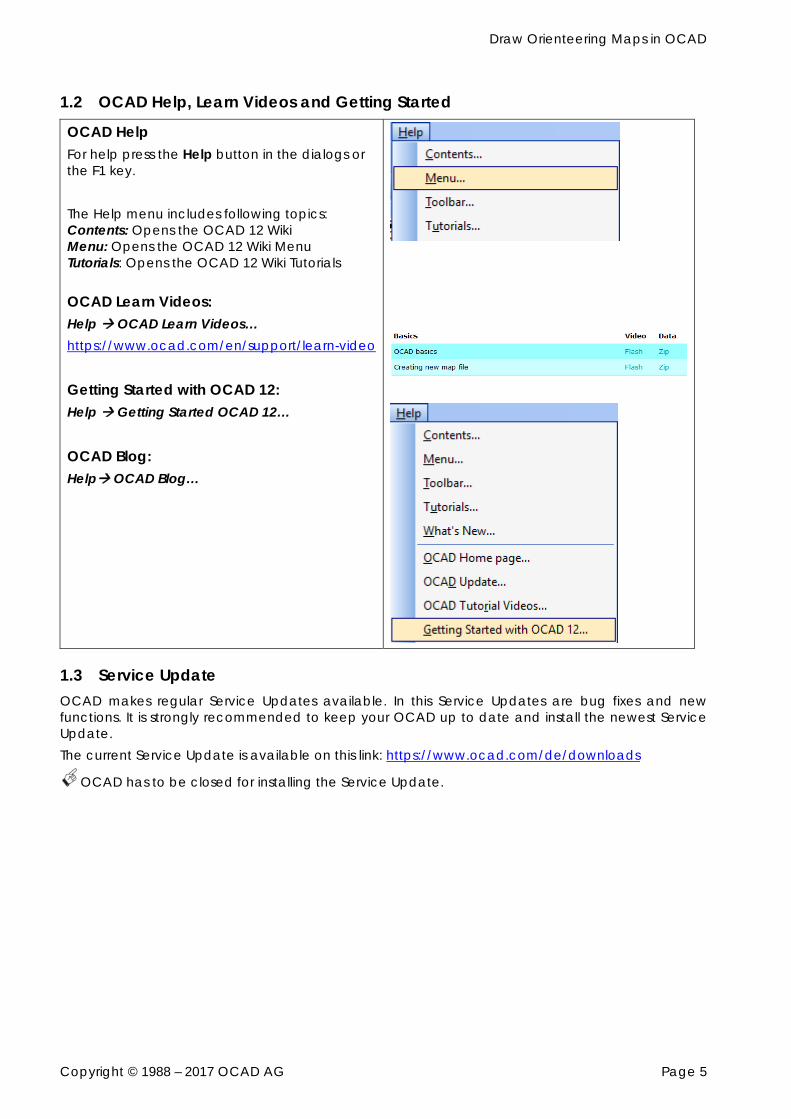
OCAD Help For help press the Help button in the dialogs or the F1 key. The Help menu includes following topics: Contents: Opens the OCAD 12 Wiki Menu: Opens the OCAD 12 Wiki Menu Tutorials: Opens the OCAD 12 Wiki Tutorials OCAD Learn Videos: Help OCAD Learn Videos… https://www.ocad.com/en/support/learn-video
Getting Started with OCAD 12: Help Getting Started OCAD 12… OCAD Blog: Help OCAD Blog…
1.3 Service Update OCAD makes regular Service Updates available. In this Service Updates are bug fixes and new functions. It is strongly recommended to keep your OCAD up to date and install the newest Service Update. The current Service Update is available on this link: https://www.ocad.com/de/downloads
OCAD has to be closed for installing the Service Update.
Draw Orienteering Maps in OCAD
Copyright © 1988 – 2017 OCAD AG Page 6
2 New Map 2.1 Start a New Map File Before start mapping you should define the map scale. Especially for map sprint maps it is time consuming job to change the map scale from 1:5’000 to 1:4’000 later on. A lot of objects have to been shifted.
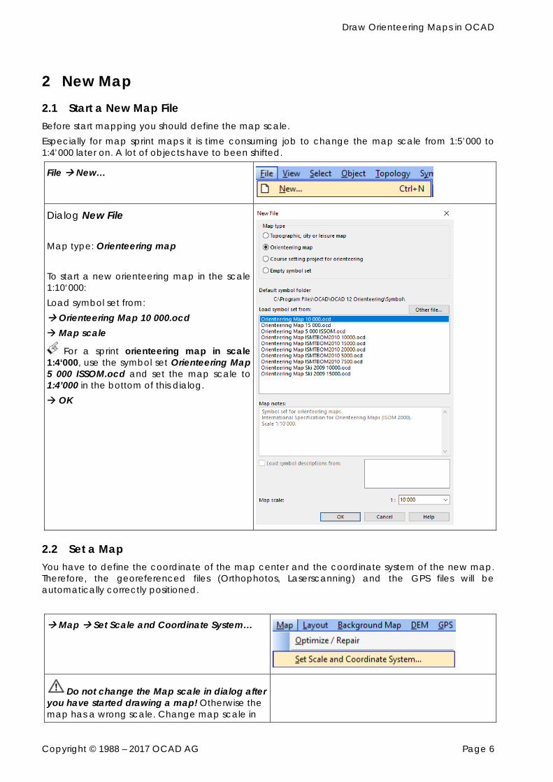
File New…
Dialog New File Map type: Orienteering map To start a new orienteering map in the scale 1:10‘000: Load symbol set from: Orienteering Map 10 000.ocd Map scale
For a sprint orienteering map in scale 1:4‘000, use the symbol set Orienteering Map 5 000 ISSOM.ocd and set the map scale to 1:4’000 in the bottom of this dialog. OK
2.2 Set a Map You have to define the coordinate of the map center and the coordinate system of the new map. Therefore, the georeferenced files (Orthophotos, Laserscanning) and the GPS files will be automatically correctly positioned.
Map Set Scale and Coordinate System…
Do not change the Map scale in dialog after you have started drawing a map! Otherwise the map has a wrong scale. Change map scale in
Draw Orienteering Maps in OCAD
Copyright © 1988 – 2017 OCAD AG Page 7
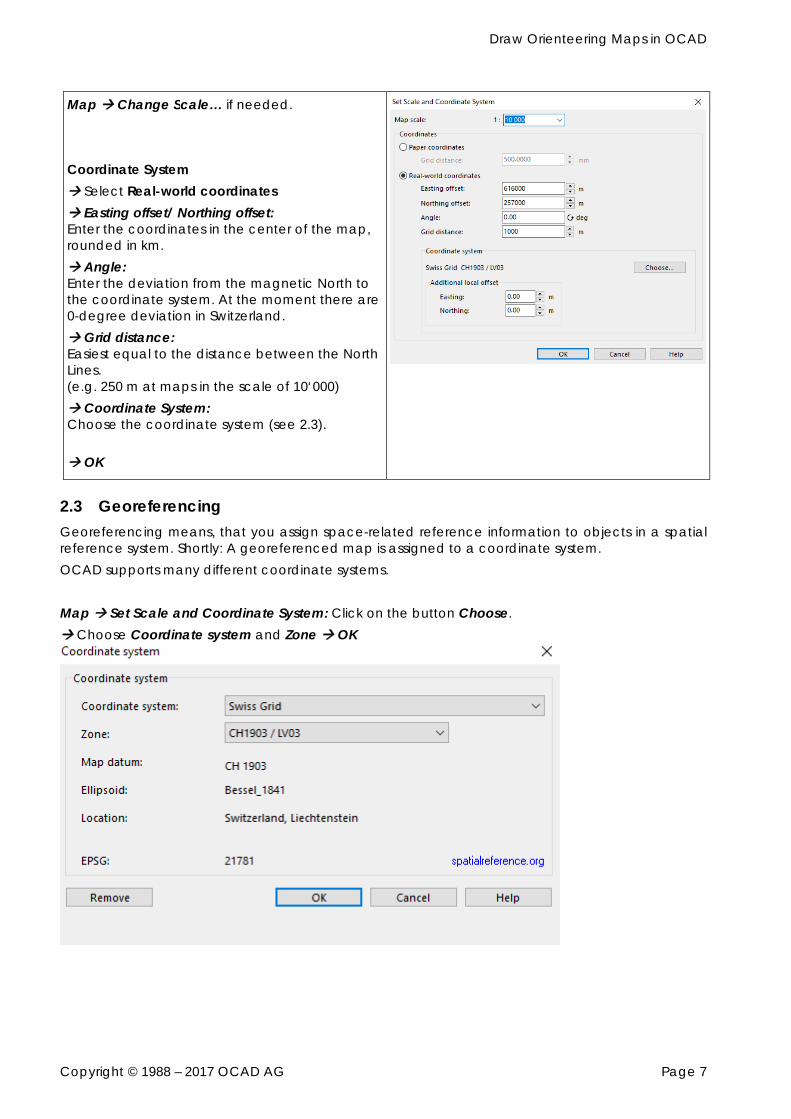
Map Change Scale… if needed. Coordinate System Select Real-world coordinates Easting offset/ Northing offset: Enter the coordinates in the center of the map, rounded in km. Angle: Enter the deviation from the magnetic North to the coordinate system. At the moment there are 0-degree deviation in Switzerland. Grid distance: Easiest equal to the distance between the North Lines. (e.g. 250 m at maps in the scale of 10‘000) Coordinate System: Choose the coordinate system (see 2.3). OK
2.3 Georeferencing Georeferencing means, that you assign space-related reference information to objects in a spatial reference system. Shortly: A georeferenced map is assigned to a coordinate system. OCAD supports many different coordinate systems. Map Set Scale and Coordinate System: Click on the button Choose. Choose Coordinate system and Zone OK
Draw Orienteering Maps in OCAD
Copyright © 1988 – 2017 OCAD AG Page 8
3 Create the Base Map for the Field Work The base map for the field work is mostly created in OCAD. More and more base maps combine orthophotos, derivates from Airborne Laserscanning like contour lines, hillshading, vegetation classification, vector data sources and old orienteering maps. (e.g. http://www.swiss-orienteering.ch/files/kommission_karten/kt/kt_2008_erfahrungen_airborne_5.pdf or http://www.ol-shop.ch/product.php?product_id=12).
3.1 Raster Base Map Typically, the orthophotos and topographic maps for orienteering maps are delivered as raster files. OCAD 12 supports the following raster files: JPG, TIFF and PNG. Orthophotos and topographic maps are mostly georeferenced. Raster files are georeferenced, when the pixels are referenced with the coordinates. Normally the georeferencing data is saved in a world file. The world file has the same file name as the raster file, but with another file extension: JPG JGW, TIFF TFW, PNG PGW. When you get base map file you have to check the coordinate system.
3.1.1 Open not Georeferenced Raster Base Map as a Background Map
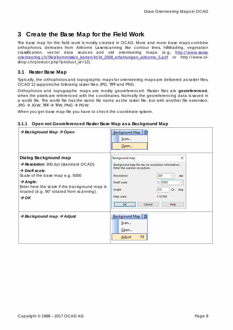
Background Map Open
Dialog Background map Resolution: 300 dpi (standard OCAD) Draft scale: Scale of the base map e.g. 5000 Angle: Enter here the scale if the background map is rotated (e.g. 90° rotated from scanning). OK
Background map Adjust
Draw Orienteering Maps in OCAD
Copyright © 1988 – 2017 OCAD AG Page 9
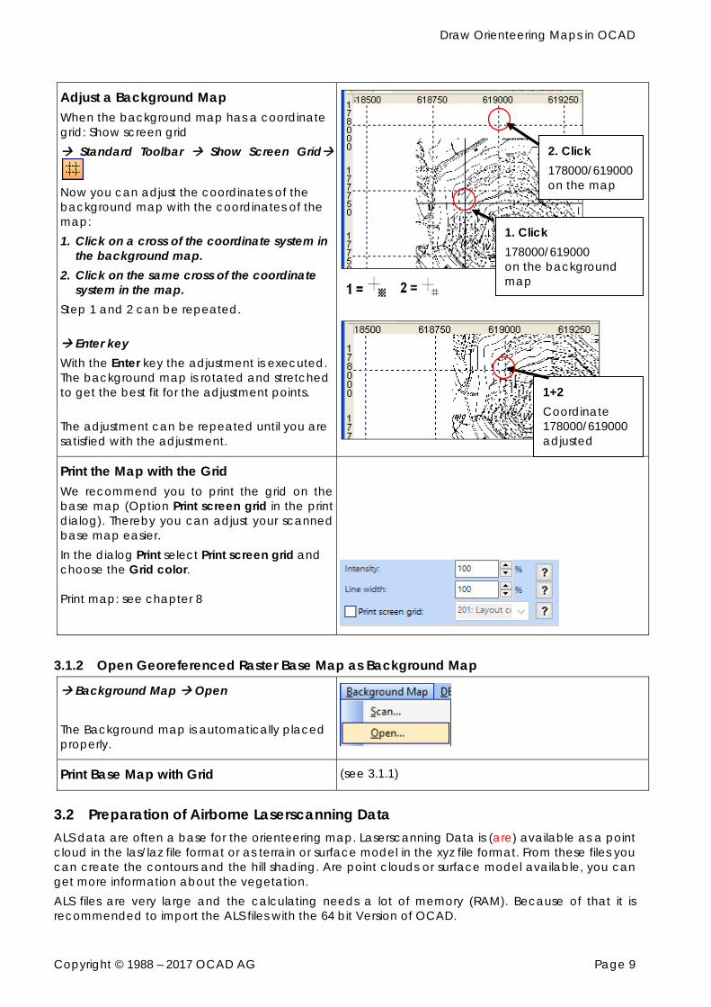
Adjust a Background Map When the background map has a coordinate grid: Show screen grid Standard Toolbar Show Screen Grid
Now you can adjust the coordinates of the background map with the coordinates of the map: 1. Click on a cross of the coordinate system in
the background map. 2. Click on the same cross of the coordinate
system in the map. Step 1 and 2 can be repeated. Enter key With the Enter key the adjustment is executed. The background map is rotated and stretched to get the best fit for the adjustment points. The adjustment can be repeated until you are satisfied with the adjustment.
Print the Map with the Grid We recommend you to print the grid on the base map (Option Print screen grid in the print dialog). Thereby you can adjust your scanned base map easier. In the dialog Print select Print screen grid and choose the Grid color. Print map: see chapter 8
3.1.2 Open Georeferenced Raster Base Map as Background Map
Background Map Open The Background map is automatically placed properly.
Print Base Map with Grid (see 3.1.1)
3.2 Preparation of Airborne Laserscanning Data ALS data are often a base for the orienteering map. Laserscanning Data is (are) available as a point cloud in the las/laz file format or as terrain or surface model in the xyz file format. From these files you can create the contours and the hill shading. Are point clouds or surface model available, you can get more information about the vegetation. ALS files are very large and the calculating needs a lot of memory (RAM). Because of that it is recommended to import the ALS files with the 64 bit Version of OCAD.
1. Click 178000/619000 on the background map
2. Click 178000/619000 on the map
1+2 Coordinate 178000/619000 adjusted
Draw Orienteering Maps in OCAD
Copyright © 1988 – 2017 OCAD AG Page 10
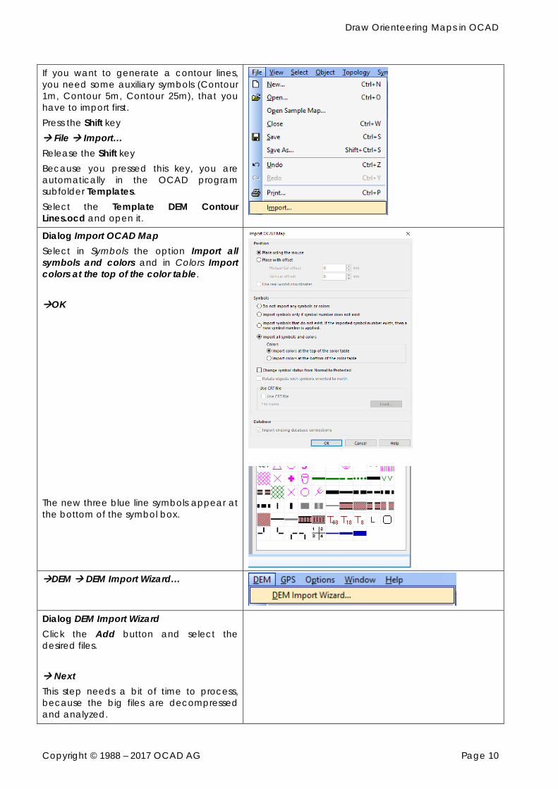
If you want to generate a contour lines, you need some auxiliary symbols (Contour 1m, Contour 5m, Contour 25m), that you have to import first. Press the Shift key File Import… Release the Shift key Because you pressed this key, you are automatically in the OCAD program subfolder Templates. Select the Template DEM Contour Lines.ocd and open it.
Dialog Import OCAD Map Select in Symbols the option Import all symbols and colors and in Colors Import colors at the top of the color table. OK The new three blue line symbols appear at the bottom of the symbol box.
DEM DEM Import Wizard…
Dialog DEM Import Wizard Click the Add button and select the desired files. Next This step needs a bit of time to process, because the big files are decompressed and analyzed.
Draw Orienteering Maps in OCAD
Copyright © 1988 – 2017 OCAD AG Page 11
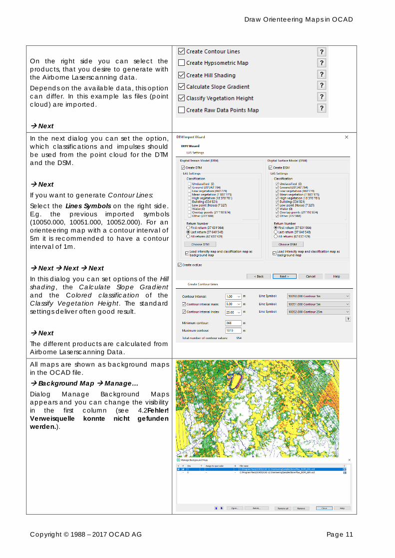
On the right side you can select the products, that you desire to generate with the Airborne Laserscanning data. Depends on the available data, this option can differ. In this example las files (point cloud) are imported. Next
In the next dialog you can set the option, which classifications and impulses should be used from the point cloud for the DTM and the DSM. Next If you want to generate Contour Lines: Select the Lines Symbols on the right side. E.g. the previous imported symbols (10050.000, 10051.000, 10052.000). For an orienteering map with a contour interval of 5m it is recommended to have a contour interval of 1m. Next Next Next In this dialog you can set options of the Hill shading, the Calculate Slope Gradient and the Colored classification of the Classify Vegetation Height. The standard settings deliver often good result. Next The different products are calculated from Airborne Laserscanning Data.
All maps are shown as background maps in the OCAD file. Background Map Manage… Dialog Manage Background Maps appears and you can change the visibility in the first column (see 4.2Fehler! Verweisquelle konnte nicht gefunden werden.).
Draw Orienteering Maps in OCAD
Copyright © 1988 – 2017 OCAD AG Page 12
3.3 Import Vector Data Vector data can also be used to create the base map. The advantage is that vector data contain point, line, area and text objects which are directly converted to map objects during the import into OCAD. It saves a lot of time because especially in urban surroundings many map objects can be created automatically instead of being digitized manually. Governmental data is generally available as DXF or Shape files. OCAD can also import other vector data formats like PDF, AI, SVG or OSM (Open Street Map).
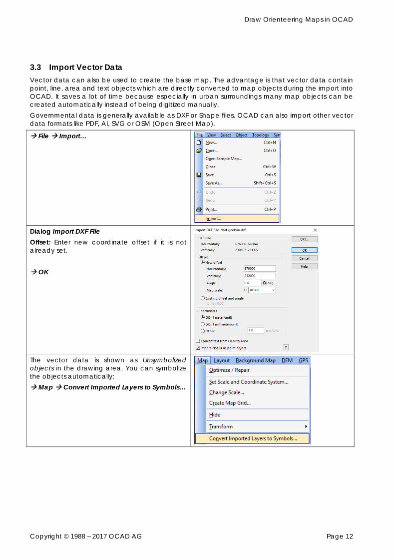
File Import…
Dialog Import DXF File Offset: Enter new coordinate offset if it is not already set. OK
The vector data is shown as Unsymbolized objects in the drawing area. You can symbolize the objects automatically: Map Convert Imported Layers to Symbols…
Draw Orienteering Maps in OCAD
Copyright © 1988 – 2017 OCAD AG Page 13
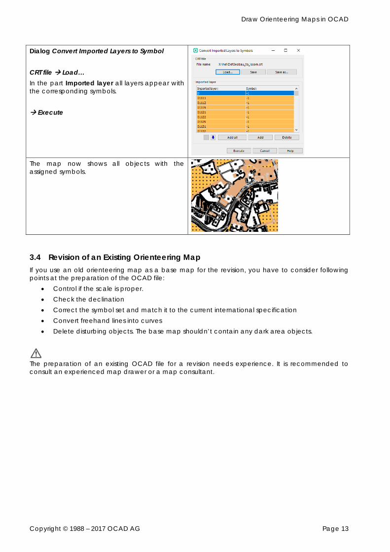
Dialog Convert Imported Layers to Symbol CRT file Load… In the part Imported layer all layers appear with the corresponding symbols. Execute
The map now shows all objects with the assigned symbols.
3.4 Revision of an Existing Orienteering Map If you use an old orienteering map as a base map for the revision, you have to consider following points at the preparation of the OCAD file:
Control if the scale is proper. Check the declination Correct the symbol set and match it to the current international specification Convert freehand lines into curves Delete disturbing objects. The base map shouldn’t contain any dark area objects.
The preparation of an existing OCAD file for a revision needs experience. It is recommended to consult an experienced map drawer or a map consultant.
Draw Orienteering Maps in OCAD
Copyright © 1988 – 2017 OCAD AG Page 14
4 Prepare your field work for digitizing 4.1 Scan Field Work, Open it as a Background Map and Adjust
Scan field work and save it in a raster format (JPG, TIFF or PNG).
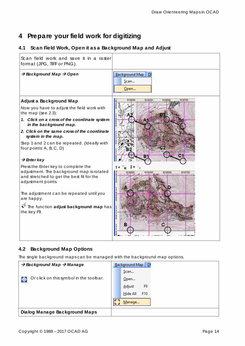
Background Map Open
Adjust a Background Map Now you have to adjust the field work with the map (see 2.3): 1. Click on a cross of the coordinate system
in the background map. 2. Click on the same cross of the coordinate
system in the map. Step 1 and 2 can be repeated. (Ideally with four points: A, B, C, D) Enter key Press the Enter key to complete the adjustment. The background map is rotated and stretched to get the best fit for the adjustment points. The adjustment can be repeated until you are happy.
The function adjust background map has the key F9.
4.2 Background Map Options The single background maps can be managed with the background map options.
Background Map Manage
Or click on this symbol in the toolbar.
Dialog Manage Background Maps
Draw Orienteering Maps in OCAD
Copyright © 1988 – 2017 OCAD AG Page 15
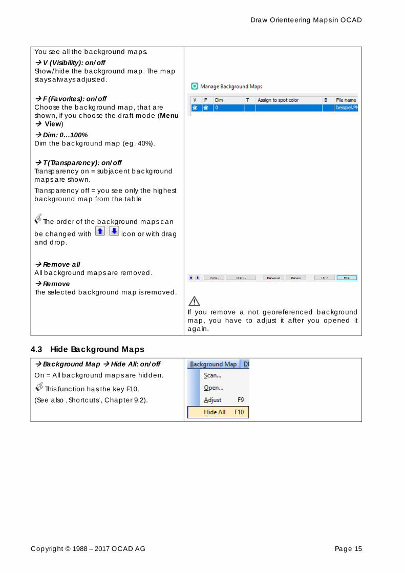
You see all the background maps. V (Visibility): on/off Show/hide the background map. The map stays always adjusted. F (Favorites): on/off Choose the background map, that are shown, if you choose the draft mode (Menu View) Dim: 0…100% Dim the background map (eg. 40%). T (Transparency): on/off Transparency on = subjacent background maps are shown. Transparency off = you see only the highest background map from the table
The order of the background maps can
be changed with icon or with drag and drop. Remove all All background maps are removed. Remove The selected background map is removed.
If you remove a not georeferenced background map, you have to adjust it after you opened it again.
4.3 Hide Background Maps Background Map Hide All: on/off On = All background maps are hidden.
This function has the key F10. (See also ‚Shortcuts’, Chapter 9.2).
Draw Orienteering Maps in OCAD
Copyright © 1988 – 2017 OCAD AG Page 16
5 Draw an Object on the Map 5.1 Drawing Generally To draw an object, click on the symbol in the symbol box first, then choose the drawing tool in the toolbar and finally draw the object in the drawing area. There are six different symbol types:
Point Object Line Object Area Object Text Object Line Text Object Rectangle Object
It is recommended to draw the point and line objects first and at the end the area objects, because they cover the background map.
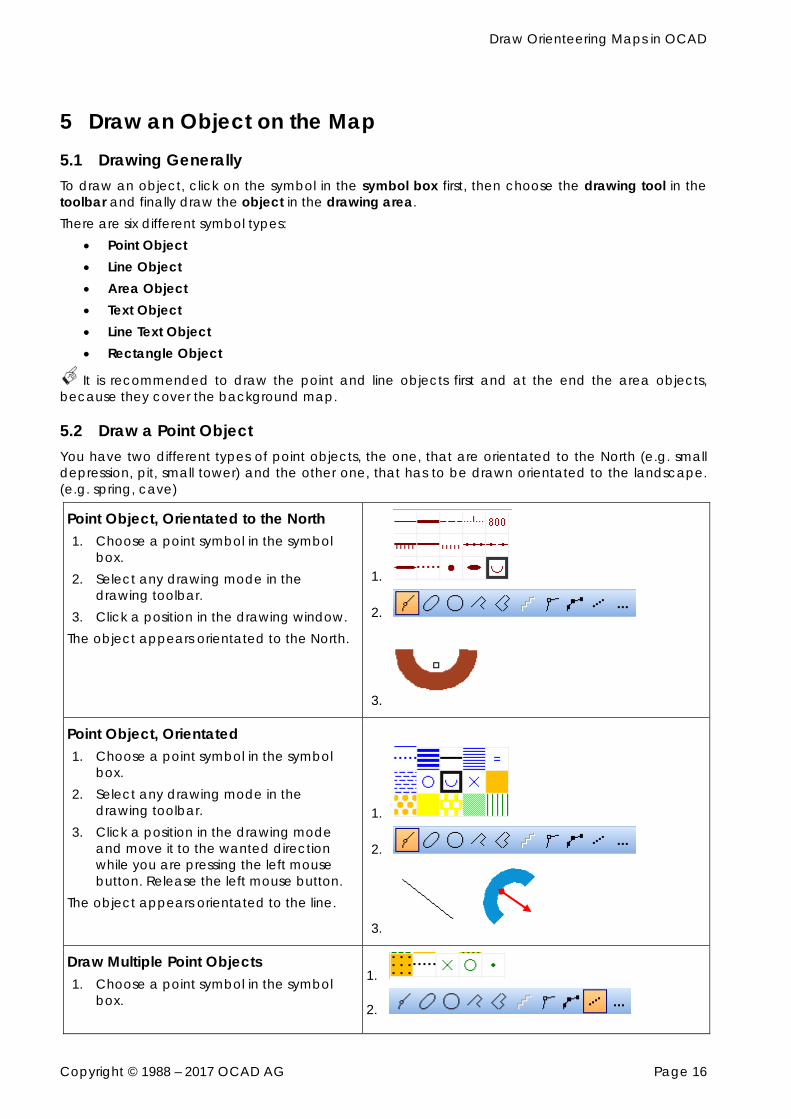
5.2 Draw a Point Object You have two different types of point objects, the one, that are orientated to the North (e.g. small depression, pit, small tower) and the other one, that has to be drawn orientated to the landscape. (e.g. spring, cave)
Point Object, Orientated to the North 1. Choose a point symbol in the symbol
box. 2. Select any drawing mode in the
drawing toolbar. 3. Click a position in the drawing window.
The object appears orientated to the North.
1.
2.
3.
Point Object, Orientated 1. Choose a point symbol in the symbol
box. 2. Select any drawing mode in the
drawing toolbar. 3. Click a position in the drawing mode
and move it to the wanted direction while you are pressing the left mouse button. Release the left mouse button.
The object appears orientated to the line.
1.
2.
3.
Draw Multiple Point Objects 1. Choose a point symbol in the symbol
box.
1.
2.
Draw Orienteering Maps in OCAD
Copyright © 1988 – 2017 OCAD AG Page 17
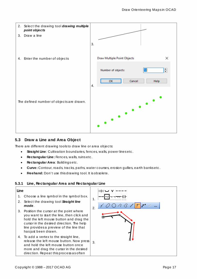
2. Select the drawing tool drawing multiple point objects
3. Draw a line
4. Enter the number of objects The defined number of objects are drawn.
3.
4.
5.3 Draw a Line and Area Object There are different drawing tools to draw line or area objects:
Straight Line: Cultivation boundaries, fences, walls, power lines etc. Rectangular Line: Fences, walls, ruins etc. Rectangular Area: Buildings etc. Curve: Contour, roads, tracks, paths, water courses, erosion gullies, earth banks etc. Freehand: Don’t use this drawing tool. It is obsolete.
5.3.1 Line, Rectangular Area and Rectangular Line
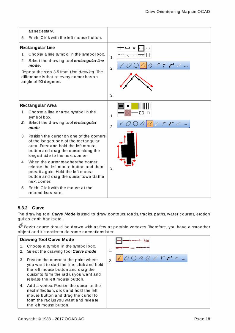
Line 1. Choose a line symbol in the symbol box. 2. Select the drawing tool Straight line
mode. 3. Position the cursor at the point where
you want to start the line, then click and hold the left mouse button and drag the cursor in the desired direction. The help line provides a preview of the line that has just been drawn.
4. To add a vertex to the straight line, release the left mouse button. Now press and hold the left mouse button once more and drag the cursor in the desired direction. Repeat this process as often
1.
2.
3.
Draw Orienteering Maps in OCAD
Copyright © 1988 – 2017 OCAD AG Page 18
as necessary. 5. Finish: Click with the left mouse button.
Rectangular Line 1. Choose a line symbol in the symbol box. 2. Select the drawing tool rectangular line
mode. Repeat the step 3-5 from Line drawing. The difference is that at every corner has an angle of 90 degrees.
1.
2.
3.
Rectangular Area 1. Choose a line or area symbol in the
symbol box. 2. Select the drawing tool rectangular
mode
3. Position the cursor on one of the corners of the longest side of the rectangular area. Press and hold the left mouse button and drag the cursor along the longest side to the next corner.
4. When the cursor reaches the corner, release the left mouse button and then press it again. Hold the left mouse button and drag the cursor towards the next corner.
5. Finish: Click with the mouse at the second least side.
1.
2.
3.
5.3.2 Curve The drawing tool Curve Mode is used to draw contours, roads, tracks, paths, water courses, erosion gullies, earth banks etc.
Bezier course should be drawn with as few as possible vertexes. Therefore, you have a smoother object and it is easier to do some corrections later.
Drawing Tool Curve Mode 1. Choose a symbol in the symbol box. 2. Select the drawing tool Curve mode
3. Position the cursor at the point where you want to start the line, click and hold the left mouse button and drag the cursor to form the radius you want and release the left mouse button.
4. Add a vertex: Position the cursor at the next inflection, click and hold the left mouse button and drag the cursor to form the radius you want and release the left mouse button.
1.
2.
Draw Orienteering Maps in OCAD
Copyright © 1988 – 2017 OCAD AG Page 19
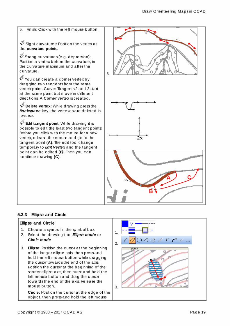
5. Finish: Click with the left mouse button.
Slight curvatures: Position the vertex at
the curvature points.
Strong curvatures (e.g. depression): Position a vertex before the curvature, in the curvature maximum and after the curvature.
You can create a corner vertex by dragging two tangents from the same vertex point. Curve: Tangents 2 and 3 start at the same point but move in different directions. A Corner vertex is created.
Delete vertex: While drawing press the Backspace key, the vertexes are deleted in reverse.
Edit tangent point: While drawing it is possible to edit the least two tangent points: Before you click with the mouse for a new vertex, release the mouse and go to the tangent point (A). The edit tool change temporary to Edit Vertex and the tangent point can be edited (B). Then you can continue drawing (C).
3.
5.3.3 Ellipse and Circle
Ellipse and Circle 1. Choose a symbol in the symbol box. 2. Select the drawing tool Ellipse mode or
Circle mode
3. Ellipse: Position the cursor at the beginning of the longer ellipse axis, then press and hold the left mouse button while dragging the cursor towards the end of the axis. Position the cursor at the beginning of the shorter ellipse axis, then press and hold the left mouse button and drag the cursor towards the end of the axis. Release the mouse button. Circle: Position the cursor at the edge of the object, then press and hold the left mouse
1.
2.
3.
B
A C
Draw Orienteering Maps in OCAD
Copyright © 1988 – 2017 OCAD AG Page 20
button while dragging the cursor to the opposite edge. Release the mouse button.
You can also drag the circle from the center point. Simply press and hold the Shift key and drag a radius.
The outlines are drawn as a Bezier curve so you can move the vertexes.
5.3.4 Tips to draw
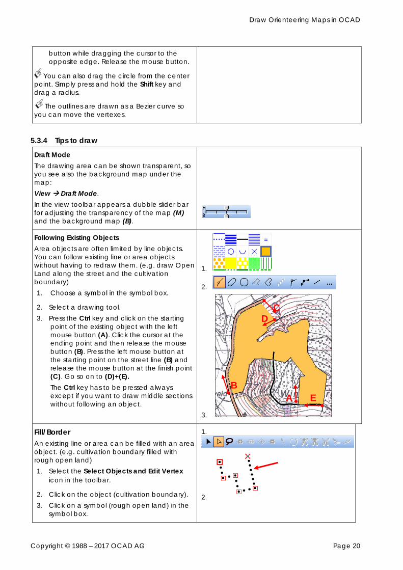
Draft Mode The drawing area can be shown transparent, so you see also the background map under the map: View Draft Mode. In the view toolbar appears a dubble slider bar for adjusting the transparency of the map (M) and the background map (B).
Following Existing Objects Area objects are often limited by line objects. You can follow existing line or area objects without having to redraw them. (e.g. draw Open Land along the street and the cultivation boundary) 1. Choose a symbol in the symbol box.
2. Select a drawing tool. 3. Press the Ctrl key and click on the starting
point of the existing object with the left mouse button (A). Click the cursor at the ending point and then release the mouse button (B). Press the left mouse button at the starting point on the street line (B) and release the mouse button at the finish point (C). Go so on to (D)+(E). The Ctrl key has to be pressed always except if you want to draw middle sections without following an object.
1.
2.
3.
Fill/Border An existing line or area can be filled with an area object. (e.g. cultivation boundary filled with rough open land) 1. Select the Select Objects and Edit Vertex
icon in the toolbar.
2. Click on the object (cultivation boundary). 3. Click on a symbol (rough open land) in the
symbol box.
1.
2.
A B
C D
E
Draw Orienteering Maps in OCAD
Copyright © 1988 – 2017 OCAD AG Page 21
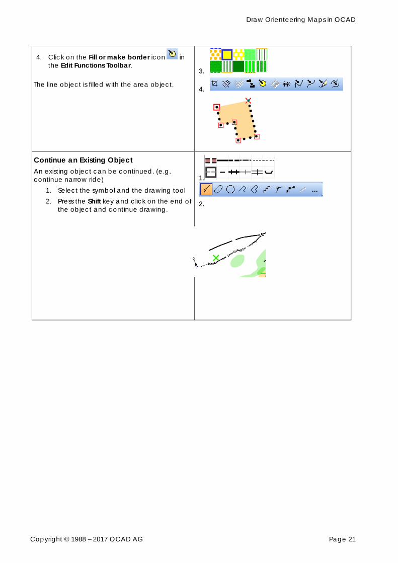
4. Click on the Fill or make border icon in the Edit Functions Toolbar.
The line object is filled with the area object.
3.
4.
Continue an Existing Object An existing object can be continued. (e.g. continue narrow ride)
1. Select the symbol and the drawing tool 2. Press the Shift key and click on the end of
the object and continue drawing.
1.
2.
Draw Orienteering Maps in OCAD
Copyright © 1988 – 2017 OCAD AG Page 22
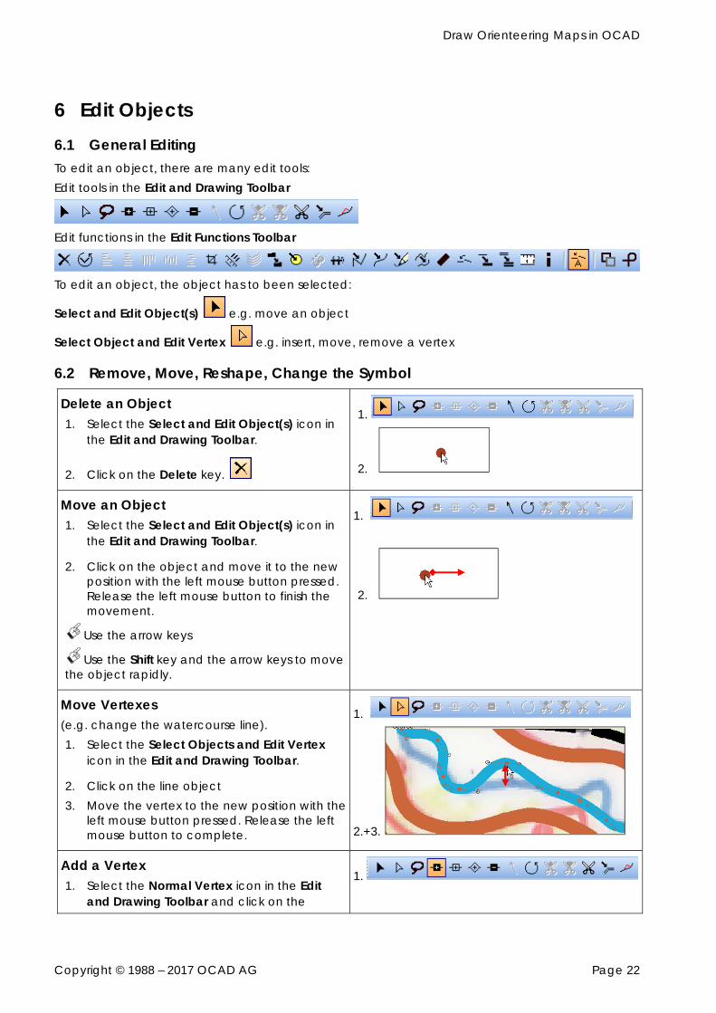
6 Edit Objects 6.1 General Editing To edit an object, there are many edit tools: Edit tools in the Edit and Drawing Toolbar
Edit functions in the Edit Functions Toolbar
To edit an object, the object has to been selected:
Select and Edit Object(s) e.g. move an object
Select Object and Edit Vertex e.g. insert, move, remove a vertex
6.2 Remove, Move, Reshape, Change the Symbol
Delete an Object 1. Select the Select and Edit Object(s) icon in
the Edit and Drawing Toolbar.
2. Click on the Delete key.
1.
2.
Move an Object 1. Select the Select and Edit Object(s) icon in
the Edit and Drawing Toolbar.
2. Click on the object and move it to the new position with the left mouse button pressed. Release the left mouse button to finish the movement.
Use the arrow keys
Use the Shift key and the arrow keys to move the object rapidly.
1.
2.
Move Vertexes (e.g. change the watercourse line). 1. Select the Select Objects and Edit Vertex
icon in the Edit and Drawing Toolbar.
2. Click on the line object 3. Move the vertex to the new position with the
left mouse button pressed. Release the left mouse button to complete.
1.
2.+3.
Add a Vertex 1. Select the Normal Vertex icon in the Edit
and Drawing Toolbar and click on the
1.
Draw Orienteering Maps in OCAD
Copyright © 1988 – 2017 OCAD AG Page 23
position to add it.
A Vertex can also be added, when you press the Shift and Ctrl key simultaneous while clicking on the object.
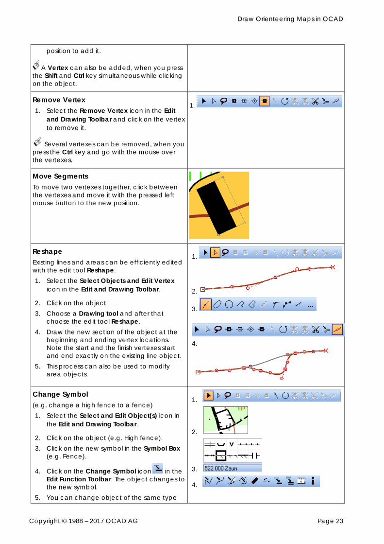
Remove Vertex 1. Select the Remove Vertex icon in the Edit
and Drawing Toolbar and click on the vertex to remove it.
Several vertexes can be removed, when you press the Ctrl key and go with the mouse over the vertexes.
1.
Move Segments To move two vertexes together, click between the vertexes and move it with the pressed left mouse button to the new position.
Reshape Existing lines and areas can be efficiently edited with the edit tool Reshape. 1. Select the Select Objects and Edit Vertex
icon in the Edit and Drawing Toolbar.
2. Click on the object 3. Choose a Drawing tool and after that
choose the edit tool Reshape. 4. Draw the new section of the object at the
beginning and ending vertex locations. Note the start and the finish vertexes start and end exactly on the existing line object.
5. This process can also be used to modify area objects.
1.
2.
3.
4.
Change Symbol (e.g. change a high fence to a fence) 1. Select the Select and Edit Object(s) icon in
the Edit and Drawing Toolbar.
2. Click on the object (e.g. High fence). 3. Click on the new symbol in the Symbol Box
(e.g. Fence).
4. Click on the Change Symbol icon in the Edit Function Toolbar. The object changes to the new symbol.
5. You can change object of the same type
1.
2.
3.
4.
Draw Orienteering Maps in OCAD
Copyright © 1988 – 2017 OCAD AG Page 24
by choosing the change all objects icon.
6.3 Edit Line Objects
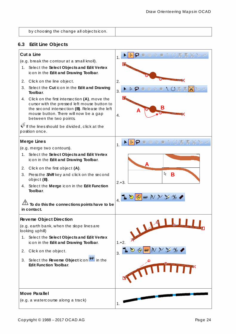
Cut a Line (e.g. break the contour at a small knoll). 1. Select the Select Objects and Edit Vertex
icon in the Edit and Drawing Toolbar.
2. Click on the line object. 3. Select the Cut icon in the Edit and Drawing
Toolbar. 4. Click on the first intersection (A), move the
cursor with the pressed left mouse button to the second intersection (B). Release the left mouse button. There will now be a gap between the two points.
If the lines should be divided, click at the position once.
1.
2.
3.
4.
Merge Lines (e.g. merge two contours). 1. Select the Select Objects and Edit Vertex
icon in the Edit and Drawing Toolbar.
2. Click on the first object (A). 3. Press the Shift key and click on the second
object (B). 4. Select the Merge icon in the Edit Function
Toolbar.
To do this the connections points have to be in contact.
1.
2.+3.
4.
Reverse Object Direction (e.g. earth bank, when the slope lines are looking uphill) 1. Select the Select Objects and Edit Vertex
icon in the Edit and Drawing Toolbar.
2. Click on the object.
3. Select the Reverse Object icon in the Edit Function Toolbar.
1.+2.
3.
Move Parallel (e.g. a watercourse along a track)
1.
B
B
A
A
Draw Orienteering Maps in OCAD
Copyright © 1988 – 2017 OCAD AG Page 25
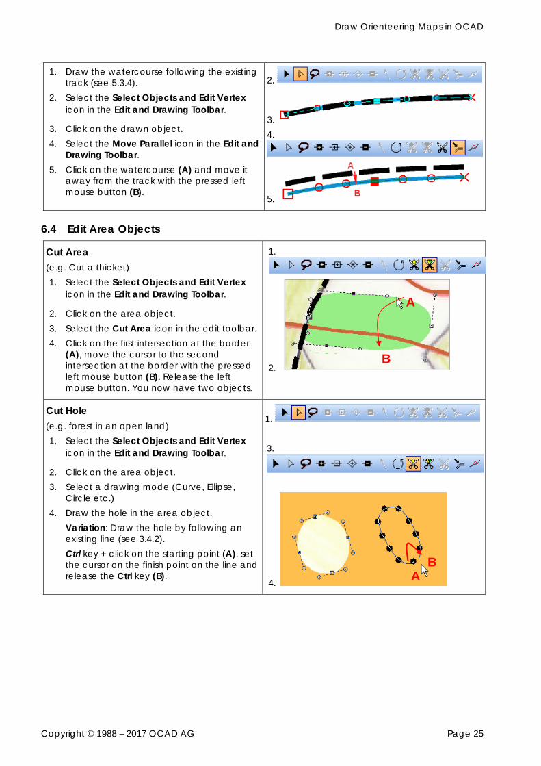
1. Draw the watercourse following the existing track (see 5.3.4).
2. Select the Select Objects and Edit Vertex icon in the Edit and Drawing Toolbar.
3. Click on the drawn object. 4. Select the Move Parallel icon in the Edit and
Drawing Toolbar. 5. Click on the watercourse (A) and move it
away from the track with the pressed left mouse button (B).
2.
3. 4.
5.
6.4 Edit Area Objects
Cut Area (e.g. Cut a thicket) 1. Select the Select Objects and Edit Vertex
icon in the Edit and Drawing Toolbar.
2. Click on the area object. 3. Select the Cut Area icon in the edit toolbar. 4. Click on the first intersection at the border
(A), move the cursor to the second intersection at the border with the pressed left mouse button (B). Release the left mouse button. You now have two objects.
1.
2.
Cut Hole (e.g. forest in an open land) 1. Select the Select Objects and Edit Vertex
icon in the Edit and Drawing Toolbar.
2. Click on the area object. 3. Select a drawing mode (Curve, Ellipse,
Circle etc.) 4. Draw the hole in the area object.
Variation: Draw the hole by following an existing line (see 3.4.2). Ctrl key + click on the starting point (A). set the cursor on the finish point on the line and release the Ctrl key (B).
1. 3.
4.
B
A
B A
Draw Orienteering Maps in OCAD
Copyright © 1988 – 2017 OCAD AG Page 26
7 Colors and Symbols 7.1 Colors In the Colors dialog (Map Colors…) you can manage the colors of the symbols. You shouldn’t change something in the list, when you don’t know what you are doing. The order of the colors in the color list regulates the overlaying: a color covers at the printing all the colors that are below. Perhaps the CMYK color value has to be changed. The CMYK color value based on a test print of the color reference test sheet of Swiss Orienteering. http://www.swiss-orienteering.ch/files/kommission_karten/solv_sept._2009_zusammenfassung_ farbstreifen-symbolstze_ocad.pdf
7.2 Symbols
7.2.1 Symbol Sets for Orienteering Maps The symbol should not be changed, because they correlate to the international Specification. The symbol sets listed below are delivered as part of OCAD 12: Orienteering Map: scales: 1:5’000, 1:10’000, 1:15’000 Orienteering Map Ski 2009: scales: 1:10‘000, 1:15‘000 Orienteering Map ISMTBOM2010: scales: 1:5‘000, 1:7‘500, 1:10‘000, 1:15‘000, 1:20‘000 Symbol sets for the course setting: Course setting 4000 – ISSOM 2007 Course setting 5000 – ISSOM 2007 Course setting 10 000 – ISOM 2000_IOF 2004 Course setting 15 000 – ISOM 2000_IOF 2004 Course setting MTBO 10 000 – ISMTBOM2010 Course setting MTBO 15 000 – ISMTBOM2010 Course setting MTBO 20 000 – ISMTBOM2010 Course setting Ski 2009 10 000 Course setting Ski 2009 15 000 Course setting Trail and Macro Orienteering 5 000
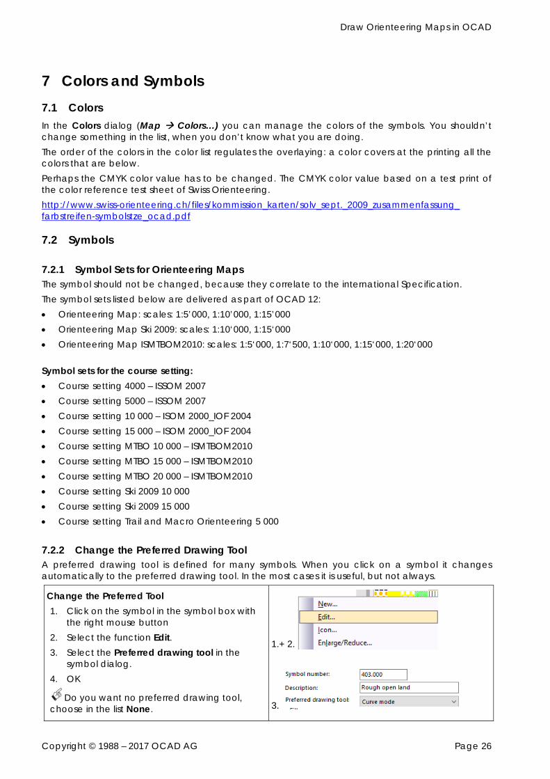
7.2.2 Change the Preferred Drawing Tool A preferred drawing tool is defined for many symbols. When you click on a symbol it changes automatically to the preferred drawing tool. In the most cases it is useful, but not always.
Change the Preferred Tool 1. Click on the symbol in the symbol box with
the right mouse button 2. Select the function Edit. 3. Select the Preferred drawing tool in the
symbol dialog. 4. OK
Do you want no preferred drawing tool, choose in the list None.
1.+ 2.
3.
Draw Orienteering Maps in OCAD
Copyright © 1988 – 2017 OCAD AG Page 27
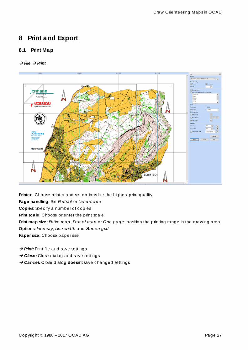
8 Print and Export 8.1 Print Map File Print
Printer: Choose printer and set options like the highest print quality Page handling: Set Portrait or Landscape Copies: Specify a number of copies Print scale: Choose or enter the print scale Print map size: Entire map, Part of map or One page; position the printing range in the drawing area Options: Intensity, Line width and Screen grid Paper size: Choose paper size Print: Print file and save settings Close: Close dialog and save settings Cancel: Close dialog doesn’t save changed settings
Draw Orienteering Maps in OCAD
Copyright © 1988 – 2017 OCAD AG Page 28
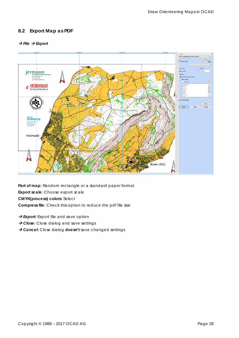
8.2 Export Map as PDF File Export
Part of map: Random rectangle or a standard paper format Export scale: Choose export scale CMYK(process) colors: Select Compress file: Check this option to reduce the pdf file size Export: Export file and save option Close: Close dialog and save settings Cancel: Close dialog doesn’t save changed settings
Draw Orienteering Maps in OCAD
Copyright © 1988 – 2017 OCAD AG Page 29
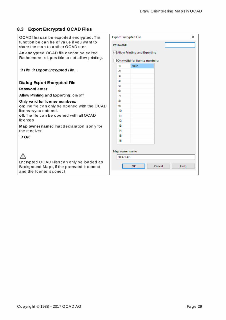
8.3 Export Encrypted OCAD Files OCAD files can be exported encrypted. This function be can be of value if you want to share the map to anther OCAD user. An encrypted OCAD file cannot be edited. Furthermore, is it possible to not allow printing. File Export Encrypted File…
Dialog Export Encrypted File Password enter Allow Printing and Exporting: on/off Only valid for license numbers: on: The file can only be opened with the OCAD licenses you entered. off: The file can be opened with all OCAD licenses. Map owner name: That declaration is only for the receiver. OK
Encrypted OCAD Files can only be loaded as Background Maps, if the password is correct and the license is correct.
Draw Orienteering Maps in OCAD
Copyright © 1988 – 2017 OCAD AG Page 30
9 Options 9.1 OCAD Preferences
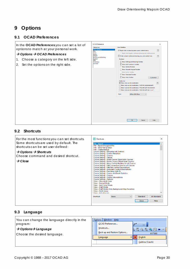
In the OCAD Preferences you can set a lot of options to match at your personal work. Options OCAD Preferences 1. Choose a category on the left side. 2. Set the options on the right side.
9.2 Shortcuts
For the most functions you can set shortcuts. Some shortcuts are used by default. The shortcuts can be set user defined: Options Shortcuts Choose command and desired shortcut. Close
9.3 Language
You can change the language directly in the program: Options Language Choose the desired language.
Draw Orienteering Maps in OCAD
Copyright © 1988 – 2017 OCAD AG Page 31
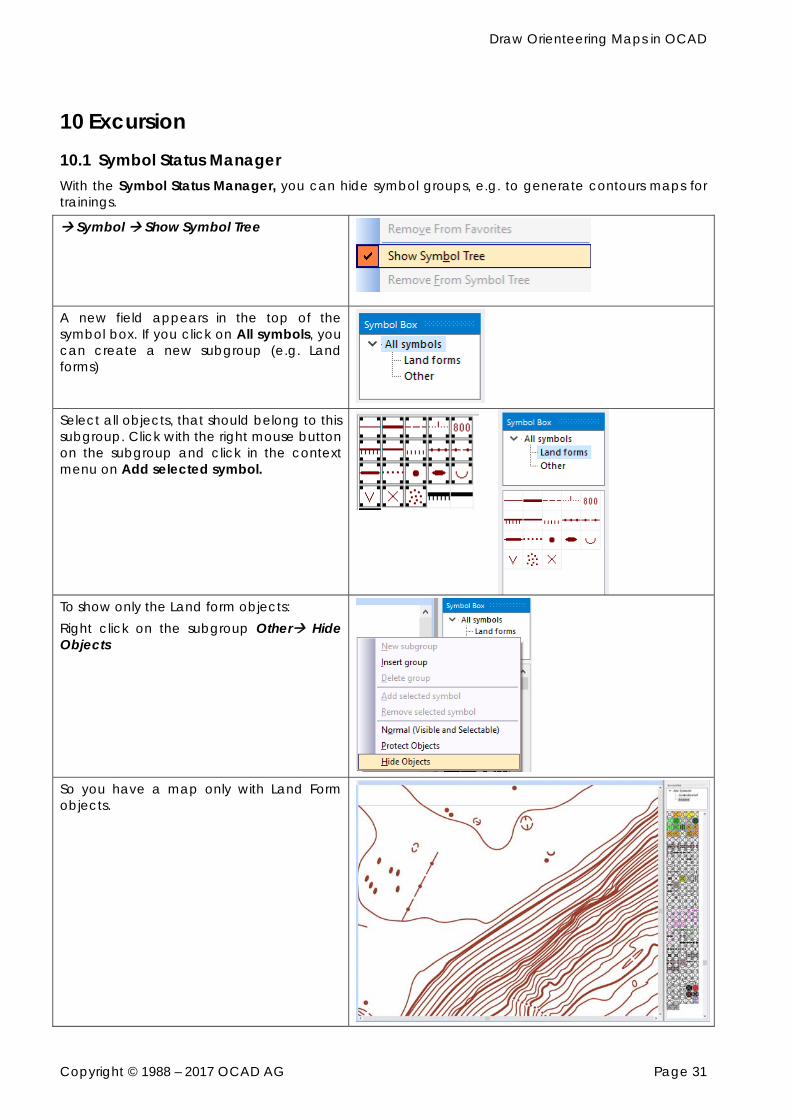
10 Excursion 10.1 Symbol Status Manager With the Symbol Status Manager, you can hide symbol groups, e.g. to generate contours maps for trainings.
Symbol Show Symbol Tree
A new field appears in the top of the symbol box. If you click on All symbols, you can create a new subgroup (e.g. Land forms)
Select all objects, that should belong to this subgroup. Click with the right mouse button on the subgroup and click in the context menu on Add selected symbol.
To show only the Land form objects: Right click on the subgroup Other Hide Objects
So you have a map only with Land Form objects.

Draw Orienteering Maps in OCAD
Copyright © 1988 – 2017 OCAD AG Page 32