Embed Size (px)
Citation preview

8/3/2019 draftsight_capitolul4
http://slidepdf.com/reader/full/draftsightcapitolul4 1/37
Emilian Popa DraftSight Design Manual 2012
- 1 -
Lesson 3
Basic Dimensioning
When you complete this lesson, you will be able to:
- Create two drawings with custom layer properties- Use absolute coordinates the command prompt and status bar
- Modify DimensionStyles and precision
- Edit Dimensions and Dimension text- Measure and rotate an Aligned Dimension
- Apply the Move and Pattern Modify commands
- Insert , Modify, and Create a Pattern of CenterMarks
- Apply the Linear, DimensionStyle, Angulat, Radius, Aligned, DimensionEdit, DimensionTextEdit,Ordinate, Continue, and CenterMark Dimension commands
- Reset the Coordinate System
Basic Dimensioning
During this lesson , you will rename a drawing, modify an existing drawing and apply Dimensions usingabsolute coordinates in the Command prompt and the graphics area.
In the first drawing you will:
- Open an existing drawing from Lesson 1 (Lesson 1-3)- Apply the Save As command and rename it Lesson 3-1
- Create a new layer called Dimension with custom properties
- Apply the DimensionStyle command and the Linear command to create a linear horizontal andvertical Dimension the Dimension layer.
- Modify the precision of the two Dimensions

8/3/2019 draftsight_capitolul4
http://slidepdf.com/reader/full/draftsightcapitolul4 2/37
Emilian Popa DraftSight Design Manual 2012
- 2 -
- Apply the Angular command to create an 80 degree Angular Dimension
- Apply the Aligned command to create an Aligned Dimension on the top right angular Line
- Apply the DimensionEdit command to modify the 60.00 Linear Dimension to the WIDTH text
- Measure the Aligned Dimension angle.
- Apply the DimensionTextEdit command to rotate the 50.00 Aligned Dimension text match theangle of an entity.
- Reset the coordinate system (CS) from the default position.
- Apply the Ordinate command to apply Dimensions on the top entity.

8/3/2019 draftsight_capitolul4
http://slidepdf.com/reader/full/draftsightcapitolul4 3/37
Emilian Popa DraftSight Design Manual 2012
- 3 -
In the second drawing you will:
- Open an existing drawing from Lesson 2 (Lesson 2-2)- Create a new layer called Annotations with custom properties.
- Apply the DimensionStyle command to set properties.
- Modify the default CenterMark size
- Apply the CenterMark command and insert CenterMarks on the Annotations layer in thedrawing.
- Apply the Pattern command to create a pattern of CenterMarks.
- Apply the Radius command to create a Radius Dimension.
- Modify the default precision setting.

8/3/2019 draftsight_capitolul4
http://slidepdf.com/reader/full/draftsightcapitolul4 4/37
Emilian Popa DraftSight Design Manual 2012
- 4 -
-
Start a DraftSight Session
1. Start a DraftSight Session
From the Windows Start menu, click Start, All Programs, Dassault Systemes, DraftSight
Dimension Toolbar
DraftSight provides a full range of Dimensioning tools and utilities. You can use a variety of Dimensioningtools to display measurements of entities or relations between them in your drawings.
By default, Dimensioning is associative. If you modify the geometry of drawing entities, Dimensionsassociated to them reflect the changes.
Display the Dimension Toolbar
8/3/2019 draftsight_capitolul4
http://slidepdf.com/reader/full/draftsightcapitolul4 5/37
Emilian Popa DraftSight Design Manual 2012
- 5 -
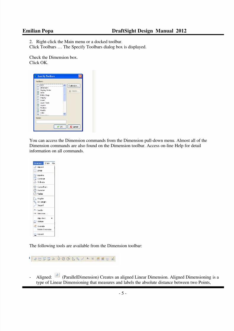
2. Right-click the Main menu or a docked toolbar.Click Toolbars … The Specify Toolbars dialog box is displayed.
Check the Dimension box.Click OK.
You can access the Dimension commands from the Dimension pull-down menu. Almost all of theDimension commands are also found on the Dimension toolbar. Access on-line Help for detail
information on all commands.
The following tools are available from the Dimension toolbar:
- Aligned: (ParallelDimension) Creates an aligned Linear Dimension. Aligned Dimensioning is a
type of Linear Dimensioning that measures and labels the absolute distance between two Points,

8/3/2019 draftsight_capitolul4
http://slidepdf.com/reader/full/draftsightcapitolul4 6/37
Emilian Popa DraftSight Design Manual 2012
- 6 -
regardless of the relative position of the axes. This lets you Dimension Lines, edges or spaces, that are
not located on the principal axes of the coordinate system, that is not parallel to the X or Y axes of theuser coordinate system (UCS).
- Linear : (LinearDimension). Creates a Horizontal, Vertical or Rotated Dimension.
- Baseline (BaselineDimension). Creates a series of Parallel Linear Dimensions that share the same
baseline. Baseline Dimensioning allows you to read the cumulative Dimension between two end
points, extending over a number of individual Dimensions within a chain.
- Continue : (ContinueDimension) Continues a Linear, Angular or Ordinate Dimension from thesecond Extension Line of the previous or a selected Dimension. Continuous Dimensioning allows one
long Dimension to be broken into shorter segements that add up to the total measurement.
- Ordinate :(OrdinateDimension) . Creates ordinate Point Dimensions. The command displays anX or Y coordinate with a Leader Line to create X-datum or Y-datum Dimensioning. The value of theX or Y coordinates is defined by the Point you specify called feature position.
-
CenterMark :( centermark) Creates a Center Mark or Center Lines of Circles and Arcs. Centermarking is used to position a mid point mark (+) or broken Lines crossing at the center of a Circle oran Arc.
- Diameter (DiameterDimension). Creates diameter Dimensions for Circles and Arcs. Unlike the
Linear Dimensioning applied on Circles (which also display the diameter), no Dimension Lines areshown. The command creates a single Leader Line to show the relationship between the value and the
entity itself.
- Radius (RadiusDimension). Creates radial Dimensions for Circles and Arcs. Radius
Dimensioning is carried out in the same way as diameter Dimensioning, the only difference being thata radius Dimension is calculated instead of a diameter measurement.
- Angular : (AngleDimension). Creates an Angular Dimension. The command lets you create the
Dimension of both the interior angle between the two legs and of the exterior angle.
- Arc Length (ArclengthDimension) Creates an Arc Length Dimension. It measures the distancealong an Arc or PolyLine Arc segment. To differentiate Arc Length Dimensions from Linear or
Angular Dimensions, an Arc symbol is displayed with the Dimension text.
- Jogged (JoggedDimension). Creates jogged radius Dimensions for Circles and Arcs. JoggedLeader Lines are typically used when a sheet is too small to display the true center point of a Radial
Dimension.
- Leader : (leader). Creates Leader Lines that connect annotations to a drawing entity. Creating a
Leader is often useful when the Dimension text or annotation does not fit next the drawing entity itmeasures or describes.
- Tolerance :(tolerance) Creates tolerances (datum indicators and Basic Dimension notation).
- Dimension Edit (EditDimensionText) Moves and rotates Dimension text of a single Dimension
entity. The default sequence of the command lets you position Dimension text dynamically.
- Dimension Rebuild : (RebuildDimension). Applies the stored Dimension system variable settingsto selected Dimensions. Unlike text styles, DimensionStyles do not automatically update when the
style is changed. Note that the Dimension update permanently overrides DimensionStyles previouslyapplied to the selected entity.

8/3/2019 draftsight_capitolul4
http://slidepdf.com/reader/full/draftsightcapitolul4 7/37
Emilian Popa DraftSight Design Manual 2012
- 7 -
- Dimension Style : (DimensionStyle). Creates and Modifies DimensionStyles . DimensionStylesare the main method used to control the way Dimensions look.
Dimension Terminology
Dimension Line
The Dimension Line is normally offset for clarity from the measured feature. The Dimension Line indicatesthe direction and length of the measured distance. Dimension Lines are usually terminated with arrows.
Angular Dimension Lines become Arcs whose centers are at the vertex of the angle.
Arrow
The arrow is a mark at the end of a Dimension Line. The arrow indicates its termination. DraftSight provides
the ability to apply various shapes other than arrows in some styles.
Extension Line
Extension Lines, sometimes called witness Lines indicate the offset of the Dimension Line from the
measured feature. Normally Extension Lines are perpendicular to the direction of the measurement.
Dimension Text.
The Dimension text can consists of words, characters, numbers, and symbols used to display the measuredtype and value of the Dimension. Dimension text format conforms to the same linear and angular units as the
default of the drawing. The text style conforms to the current text style.
Leader
The Leader is a radial Line used to Point from the Dimension text to the Arc or Circle whose diameter orradius is being Dimensioned.
Center Mark
The center mark is used to position a mid point mark (+) or broken Lines crossing at the center of a Circle oran Arc.
Open an Existing Drawing
3. Click the Open icon on the Standard toolbar.The Open dialog box is displayed.
4. Double-click Lesson 2-3. The drawing is displayed in the graphics area.

8/3/2019 draftsight_capitolul4
http://slidepdf.com/reader/full/draftsightcapitolul4 8/37
Emilian Popa DraftSight Design Manual 2012
- 8 -
5. Save the Drawing
Click, File, Save As from the Menu bar.
Enter File name: Lesson 3-1.
Click Save from the Save As … dialog box.
Use the Save As command to save the drawing under a different name or in a differentlocation.
Create a New Layer
In this section, create a new layer called Dimension with custom properties.

8/3/2019 draftsight_capitolul4
http://slidepdf.com/reader/full/draftsightcapitolul4 9/37
Emilian Popa DraftSight Design Manual 2012
- 9 -
6. Create a new Layer.
Click the Layers Manager icon . The Layers Manager dialog box is displayed.
Click the New Layer icon . The new default name is Layer 1.
Rename this layer Dimension.
Dimension is the new layer name.
7. Set the LineColor
Double-click the LineColor cell for the Dimension layer.
Click Red.
By default, Continuous LineStyle is selected.
8. Activate the Dimenion Layer.
Click the Dimension layer in the Layers Manager dialog box.
Click the Activate Layer button. A yellow arrow is displayed in the Dimension Status box.

8/3/2019 draftsight_capitolul4
http://slidepdf.com/reader/full/draftsightcapitolul4 10/37
Emilian Popa DraftSight Design Manual 2012
- 10 -
9. Close the Layers Manager Dialog box.
Click OK.
10. Save the Drawing.
Click the Save icon on the Standard toolbar.
Working with Dimensions
DimensionStyles are the main method used to control the way Dimensions look. You create and manage
DimensionStyles by using the DimensionStyles Manager dialog box.
Dimension Styles Manager Dialog Box
Use the style name, input and selection dialog to either store the current settings as a Dimensioning style , orto select a predefined style as the default.
DimensionStyle Command
The DimensionStyle command on the Dimension toolbar provides the ability to create and modify
DimensionStyles, DimensionStyles are the main method used to control the way Dimensions look.
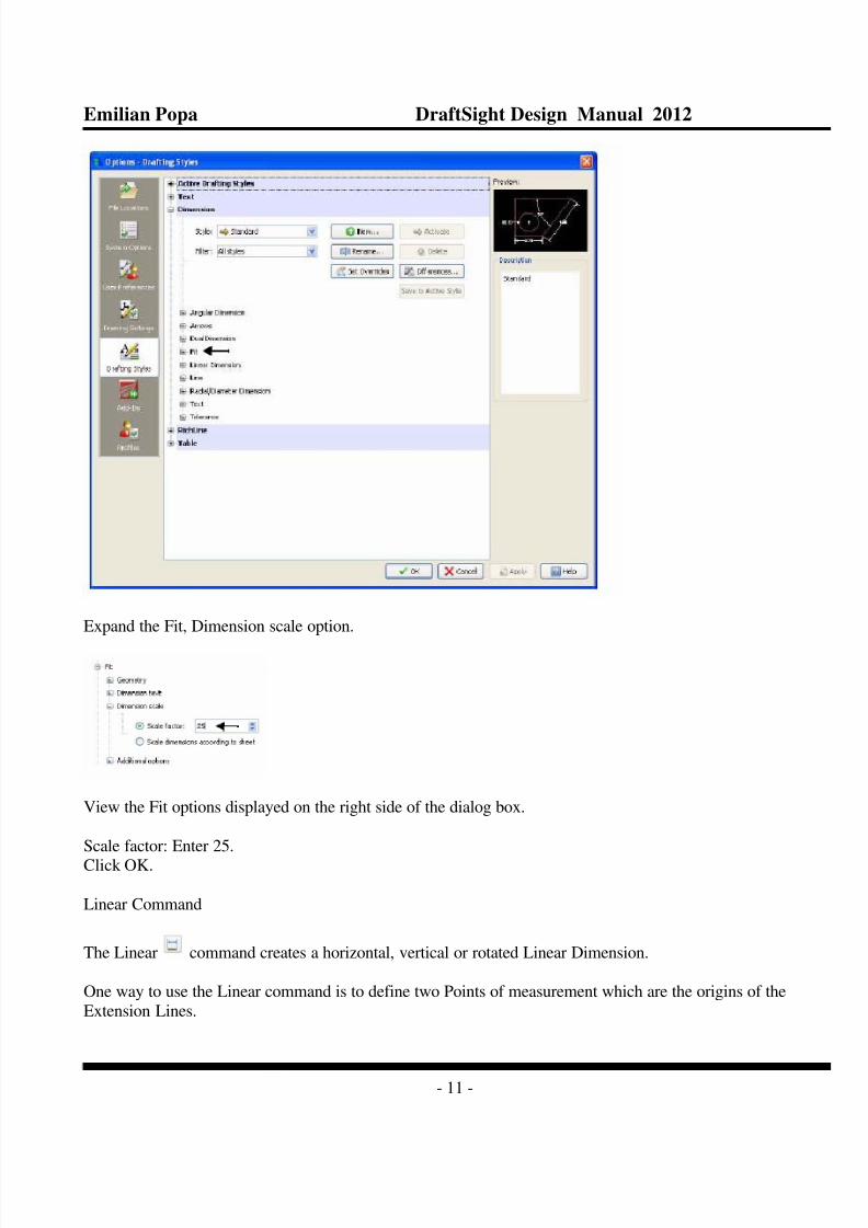
11. Set DimensionStyle
Click the DimensionStyle icon on the Dimension toolbar.
The Options – Drafting Styles dialog box is displayed with the Dimensions option expanded.
8/3/2019 draftsight_capitolul4
http://slidepdf.com/reader/full/draftsightcapitolul4 11/37
Emilian Popa DraftSight Design Manual 2012
- 11 -
Expand the Fit, Dimension scale option.
View the Fit options displayed on the right side of the dialog box.
Scale factor: Enter 25.
Click OK.
Linear Command
The Linear command creates a horizontal, vertical or rotated Linear Dimension.
One way to use the Linear command is to define two Points of measurement which are the origins of the
Extension Lines.

8/3/2019 draftsight_capitolul4
http://slidepdf.com/reader/full/draftsightcapitolul4 12/37
Emilian Popa DraftSight Design Manual 2012
- 12 -
The Command prompt also offers you to select an entity to be Dimensioned. Press Enter at the prompt of
the command. You are then requested to select a drawing entity to be Dimensioned, Lines, PolyLines,
Circles, and Arcs can be selected. The start and end points of linear entities, or the diameter of the circularentities are evaluated for the measurement.
Once the Points of measurement are defined, you are prompted to indicate the position for the Dimension
Line.
The distance between the two Points is measured along the X axis for a Horizontal Dimensioning and alongthe Y axis for a Vertical Dimensioning. For oblique measurements the Rotated option is provided.
The measurement is placed is Dimension text based on the definitions of the current DimensionStyle.
Create Two Linear Dimensions
Dimension the rectangle in the graphics area. Create a Horizontal and Vertical Dimension.
12. Create a Horizontal Dimension
Click the Linear icon on the Dimension toolbar.
Click the lower left end point of the rectangle.
Click the lower right end point of the rectangle.

8/3/2019 draftsight_capitolul4
http://slidepdf.com/reader/full/draftsightcapitolul4 13/37
Emilian Popa DraftSight Design Manual 2012
- 13 -
Click a position about one grid below the bottom Horizontal Line.
The Note option provides the ability to modify the Dimension text using the Note editordialog box.
13. Create a Vertical Dimension
Press the Enter key to repeat the command.
Click the left Vertical Line of the rectangle.

8/3/2019 draftsight_capitolul4
http://slidepdf.com/reader/full/draftsightcapitolul4 14/37
Emilian Popa DraftSight Design Manual 2012
- 14 -
Click a position about two grid spaces to the left of the left Vertical Line. The rectangle now has a
Vertical and Horizontal Dimension
The Angle option changes the angle of the dimension text.
Modify Dimension Precision Display
The present Vertical and Horizontal Dimensions display four decimal places. Modify the precision of theDimensions.
14. Modify Dimension Precision

8/3/2019 draftsight_capitolul4
http://slidepdf.com/reader/full/draftsightcapitolul4 15/37
Emilian Popa DraftSight Design Manual 2012
- 15 -
Click the DimensionStyle icon on the Dimension toolbar. The DimensionStyles Manager dialog box is
displayed.
Expand the Linear Dimensions option.
View the Linear Dimensions options displayed on the right side of the dialog box.
Precision: Select 0.00 from the drop-down menu.
Click OK.
15. Save the Drawing
Click the Save icon on the Standard toolbar.
Angular Command

8/3/2019 draftsight_capitolul4
http://slidepdf.com/reader/full/draftsightcapitolul4 16/37
Emilian Popa DraftSight Design Manual 2012
- 16 -
The Angular command provides the ability to Dimension angles in your drawing. The tool creates the
Dimension of both the interior angle between the two legs and of the exterior angle using various methods:
- Three Points: (vertex/poiny/point)- Between two nonparallel Lines
- On an Arc Between the two end points of the Arc, with the center as the vertex
- On a Circle, between two Points on the Circle, with the center as the vertex.
Create an Angular Dimension
Create an 80 degree Angular Dimension.
16 Create an Angular Dimension
Click the Angular icon from the Dimension toolbar.
Be sure the SNAP is set to off. Click the Snap button on the status bar.
View the The command window for the display: <Snap Off>
Click the Horizontal Line as illustrated.
Click the left bottom Angular Line.

8/3/2019 draftsight_capitolul4
http://slidepdf.com/reader/full/draftsightcapitolul4 17/37
Emilian Popa DraftSight Design Manual 2012
- 17 -
Click a position inside the entity as illustrated.
16. Save the Drawing.
Click the Save icon on the Standard toolbar.
Align Command
The Aligned command provides the ability to create an aligned Dimension. Aligned Dimensioning is a
type of linear Dimensioning that measures and labels the absolute distance between two Points.
Create an Aligned Dimension
Create an aligned Dimension on the top right Angular Line.
17. Create an Aligned Dimension
Click the Aligned icon on the Dimension toolbar.
Click the bottom right end point of the right side Diagonal Line as illustrated.

8/3/2019 draftsight_capitolul4
http://slidepdf.com/reader/full/draftsightcapitolul4 18/37
Emilian Popa DraftSight Design Manual 2012
- 18 -
Click the top left end point of the right Diagonal Line as illustrated.
Place the Dimension.
Click a position above the Line as illustrated.
Edit Dimensions and Dimension Text
DraftSight provides several Dimensioning commands which allows you to edit or format the Dimension textduring the creation of the current Dimension.
DimensionEdit Command
The DimensionEdit command provides the ability to replace the Dimension text with new text, rotate the
existing text, move the text to a new position, and if necessary, restore the text back to its home position.Home position is the position defined by the current style. In addition , the provided options allow you to
modify the angle of the Extension Lines, normally perpendicular relative to the direction of the Dimension
Line (Oblique) option.

8/3/2019 draftsight_capitolul4
http://slidepdf.com/reader/full/draftsightcapitolul4 19/37
Emilian Popa DraftSight Design Manual 2012
- 19 -
DimensionTextEdit Command
The DimensionTextEdit command provides the ability to move and rotate Dimension text of any single
Dimension entity.
The default sequence of the (DimTextEdit) command lets you position Dimension text dynamically.
After calling the command, select a Dimension entity. Then point to the drawing to determine the new
position of the Dimension text.
Dimension Text Alignment Options
- The Angle option rotates the Dimension text about its center by the angle you specify.
- The Center option moves the text to a left justified position within the Dimension.
- The Reset option undoes the move of Dimension text and returns it to the original position.- The Left option moves the text to a left justified position within the Dimension.
- The Right option moves the text to a left justified position within the Dimension.
Modify the Linear Dimension Text
Modify the 60.00 Linear Dimension to WIDTH text.
18. Modify the Linear Dimension Text
Click the DimensionEdit icon on the Dimension toolbar.
Use the New option.

8/3/2019 draftsight_capitolul4
http://slidepdf.com/reader/full/draftsightcapitolul4 20/37
Emilian Popa DraftSight Design Manual 2012
- 20 -
Click the 60.00 Dimension text as illustrated.
19. Unde the Modified Linear Dimension
20. Save the Drawing.
Click the Save icon on the Standard toolbar.
Measure and Rotate an Aligned Dimension
First measure the Aligned Dimension angle. Rotate the 50.00 Aligned Dimension text to match angle of the
entity.

8/3/2019 draftsight_capitolul4
http://slidepdf.com/reader/full/draftsightcapitolul4 21/37
Emilian Popa DraftSight Design Manual 2012
- 21 -
21. Measure the Aligned Dimension Angle.
Click Tools, Inquiry, Get Distance from the Main Menu.
Make sure the EntitySnap function is set to ON. Click the ESnap button on the Status bar.
View the command window : <ESnaps On>
Click the top left end point of the Aligned Dimension.
Click the bottom right end point of the Aligned Dimension.
View the angle in the XY Plane in the command window:

8/3/2019 draftsight_capitolul4
http://slidepdf.com/reader/full/draftsightcapitolul4 22/37
Emilian Popa DraftSight Design Manual 2012
- 22 -
Angle in XY Plane is 300.
23.Rotate the Aligned Dimension Text.
Click the DimensionTextEdit icon on the Dimension toolbar.
Click the 50.00 aligned Dimension text as illustrated.

8/3/2019 draftsight_capitolul4
http://slidepdf.com/reader/full/draftsightcapitolul4 23/37
Emilian Popa DraftSight Design Manual 2012
- 23 -
Move Command
Apply the Move command to reposition drawing entities within the coordinate system without changing
their orientation or size.
24. Move the Selected Entities
Click The Move icon on the Modify toolbar.
Select all 7 entities as illustrated.
Click the end point as illustrated.

8/3/2019 draftsight_capitolul4
http://slidepdf.com/reader/full/draftsightcapitolul4 24/37
Emilian Popa DraftSight Design Manual 2012
- 24 -
Coordinate System Command
A coordinate systems determines each Point of a drawing surface or entity unambiguously. DraftSight usesthe Cartesian coordinate system consisting of three coordinate axes. Axes are arranged orthogonally crossing
at the origin. All aces use the same measurements.
Reset the coordinate system (CCS) from the default position. Use the CCS command to set coordinate
systems and save, restore, rename and delete them.
Reset the Coordinate System
25. Reset the Coordinate System
Set the coordinate system position to the bottom left point of the top entity.
Click Snap On from the Status bar. The command window displays <Snap On>.Click ESnap On from the Status bar. The command window displays <ESnap On>Click Ortho On from the Status bar. The command window displays <Ortho On>.
8/3/2019 draftsight_capitolul4
http://slidepdf.com/reader/full/draftsightcapitolul4 25/37
Emilian Popa DraftSight Design Manual 2012
- 25 -
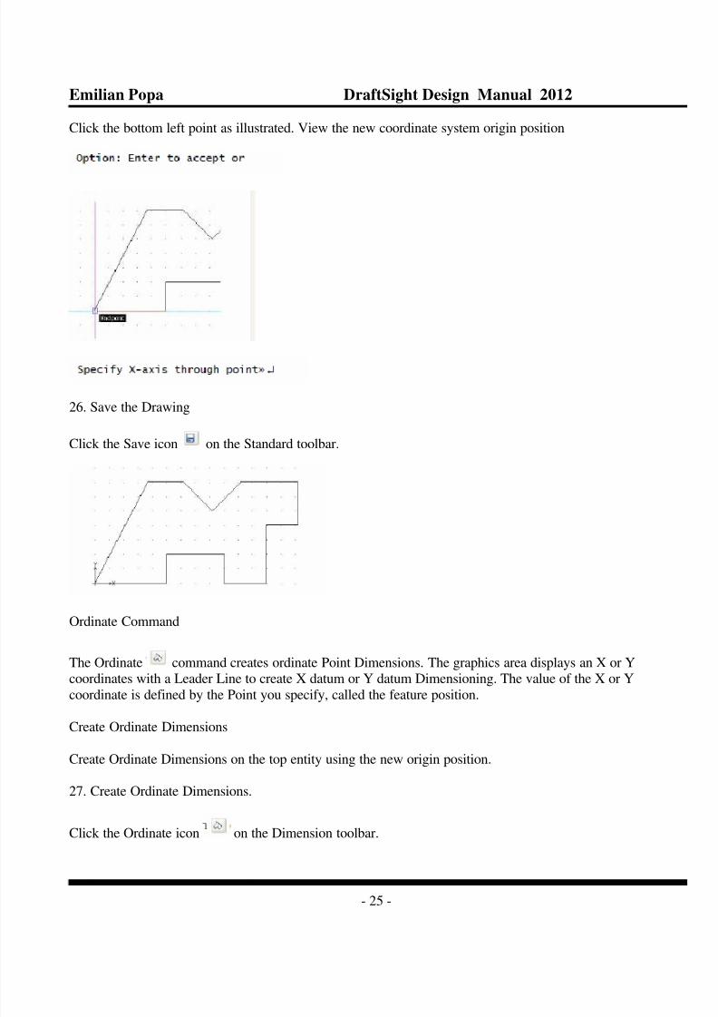
Click the bottom left point as illustrated. View the new coordinate system origin position
26. Save the Drawing
Click the Save icon on the Standard toolbar.
Ordinate Command
The Ordinate command creates ordinate Point Dimensions. The graphics area displays an X or Ycoordinates with a Leader Line to create X datum or Y datum Dimensioning. The value of the X or Y
coordinate is defined by the Point you specify, called the feature position.
Create Ordinate Dimensions
Create Ordinate Dimensions on the top entity using the new origin position.
27. Create Ordinate Dimensions.
Click the Ordinate icon on the Dimension toolbar.

8/3/2019 draftsight_capitolul4
http://slidepdf.com/reader/full/draftsightcapitolul4 26/37
Emilian Popa DraftSight Design Manual 2012
- 26 -
Make sure the Snap mode is set to OFF. Click Snap on the Status bar. The command window
will display <Snap Off>.
Make sure that Ortho mode is set to ON. Click Ortho on the Status bar. The command
window will display <Ortho on>.
Click the bottom left end point.
Click a position directly under the end point. The command window displays:

8/3/2019 draftsight_capitolul4
http://slidepdf.com/reader/full/draftsightcapitolul4 27/37
Emilian Popa DraftSight Design Manual 2012
- 27 -
Click the Continue icon on the Dimension toolbar.
Click all the end points from left to right as illustrated.
28. Save the Drawing
Click the Save icon on the Standard toolbar.

8/3/2019 draftsight_capitolul4
http://slidepdf.com/reader/full/draftsightcapitolul4 28/37
Emilian Popa DraftSight Design Manual 2012
- 28 -
CenterMarks Command
The CenterMark command provides the ability to mark the center of a Circle or Arc. Yu can display the
center as a center mark (a Point) or as a Center Line (a broken Line crossing the center).
In the next section, open Lesson 2-2 and create a new layer called Annotations. Insert CenterMarks on the
Annotations layer in the drawing.
Open an Existing Drawing
1. Click the Open icon on the Standard toolbar. The Open dialog box is displayed.
2. Double-click Lesson 2-2.
Create a New Layer
In this section, create a new layer called Annotations.
Apply custom properties.
3. Create the New Layer.

8/3/2019 draftsight_capitolul4
http://slidepdf.com/reader/full/draftsightcapitolul4 29/37
Emilian Popa DraftSight Design Manual 2012
- 29 -
Click the Layers Manager icon . The Layers Manager dialog box is displayed.
Click the New Layer icon . The new default name is Layer 1.
Rename this Layer Annotations.
Annotations is the new layer name.
4. Set the LineColor
New layers are automatically assigned the LineColor white.
Double-click the LineColor cell for the Annotations layer.
Click Magenta.
Click OK.
5. Save the Drawing.
Click File, Save As from the Menu bar.
Enter File name: Lesson 3-2.
Click Save from the Save As … dialog box.
DimensionStyle Command
The DimensionStyle command on the Dimension toolbar provides the ability to create and modifyDimensionStyles. Remember , DimensionStyles are the main method used to control the way Dimensionslook.
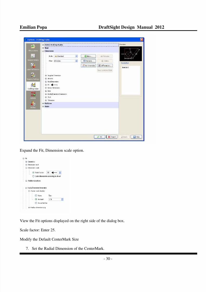
6. Set DimensionStyle
Click the DimensionStyle icon on the Domension toolbar. The DimensionStyles Manager dialog box is
displayed.
The Options-Drafting Styles dialog box is displayed with the Dimensions option expanded.
8/3/2019 draftsight_capitolul4
http://slidepdf.com/reader/full/draftsightcapitolul4 30/37
Emilian Popa DraftSight Design Manual 2012
- 30 -
Expand the Fit, Dimension scale option.
View the Fit options displayed on the right side of the dialog box.
Scale factor: Enter 25.
Modify the Default CenterMark Size
7. Set the Radial Dimension of the CenterMark.

8/3/2019 draftsight_capitolul4
http://slidepdf.com/reader/full/draftsightcapitolul4 31/37
Emilian Popa DraftSight Design Manual 2012
- 31 -
Expand Radial/Diameter Dimensions, Center mark display from the Navigation box.
Click As mark on the dialog.
Enter 2.5 for Size.
Click OK.
8. Insert CenterMarks.
Click the CenterMark icon on the Draw toolbar.
Click the circumference of the bottom left Circle as illustrated.
Click the circumference of the top left Circle.
Click the circumference of the top right Circle
Click the circumference of the bottom right Circle.
8/3/2019 draftsight_capitolul4
http://slidepdf.com/reader/full/draftsightcapitolul4 32/37
Emilian Popa DraftSight Design Manual 2012
- 32 -
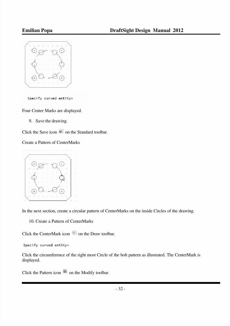
Four Center Marks are displayed.
9. Save the drawing.
Click the Save icon on the Standard toolbar.
Create a Pattern of CenterMarks
In the next section, create a circular pattern of CenterMarks on the inside Circles of the drawing.
10. Create a Pattern of CenterMarks
Click the CenterMark icon on the Draw toolbar.
Click the circumference of the right most Circle of the bolt pattern as illustrated. The CenterMark is
displayed.
Click the Pattern icon on the Modify toolbar.

8/3/2019 draftsight_capitolul4
http://slidepdf.com/reader/full/draftsightcapitolul4 33/37
Emilian Popa DraftSight Design Manual 2012
- 33 -
The Format Pattern dialog box is displayed .Set the options.
Click the Circular button.
Click the selected Entities icon.
Click the Horizontal Line of the Center Mark display.
Click the Vertical Line of the Center Mark display.
It may be necessary to use the scroll wheel to zoom into the entity.
Base pattern on : Fill Angle and total number of Elements

8/3/2019 draftsight_capitolul4
http://slidepdf.com/reader/full/draftsightcapitolul4 34/37
Emilian Popa DraftSight Design Manual 2012
- 34 -
Fill angle: Enter 360.
Total number : Enter 6
Click the Axis Point icon. The graphics area is displayed.
Click the center point of the large Circle as illustrated.
The Pattern dialog box is displayed.
View the Axis point X: 100.00 and the Axis point Y: = 100.00
The Orient elements about axis box is check by default. This options provides the ability to have theCenterMarks rotate about the large Circle.
Click OK.

8/3/2019 draftsight_capitolul4
http://slidepdf.com/reader/full/draftsightcapitolul4 35/37
Emilian Popa DraftSight Design Manual 2012
- 35 -
11. Activate the Annotations Layer
Click Annotations from the Layers Manager drop-down menu.
Radius Command
The Radius command provides the ability to create Radial Dimensions for Circles and Arcs. RadiusDimensioning is carried out in the same way as Diameter Dimensioning, the only difference being that aRadius Dimension is calculated instead of a diameter measurement. Create a Radial Dimension for the large
Circle.
12. Create a Radius Dimension
Click the Radius icon on the Dimension toolbar.
Click the circumference of the large Circle.

8/3/2019 draftsight_capitolul4
http://slidepdf.com/reader/full/draftsightcapitolul4 36/37
Emilian Popa DraftSight Design Manual 2012
- 36 -
Click a position diagonally to the right.
The dimension text = 30.000
13. Save the Drawing
Click the Save icon on the Standard toolbar.
14. Modify the Precision
Click the DimensionStyle icon on the Dimension toolbar.
The Options-Drafting Styles dialog box is displayed with the Dimensions option expanded.
Expand Linear Dimension in the navigation box.
View the Linear Dimensions options displayed on the right side of the dialog box.
Precision : Select 0.00 from the drop-down menu.
Click OK.

8/3/2019 draftsight_capitolul4
http://slidepdf.com/reader/full/draftsightcapitolul4 37/37
Emilian Popa DraftSight Design Manual 2012
37
15. Save the Drawing.
Click the Save icon on the Standard toolbar.
You are finished with this section.


