Embed Size (px)
Citation preview
CITY OF GREATER SUDBURY
ENGINEERING SERVICES
DRAFTING STANDARDS
MANUAL
CAD / METRIC
AS DISPLAYED ONLINE 2016-01-19
https://www.greatersudbury.ca/business/engineering-standards/drafting-procedures/
CITY OF GREATER SUDBURY
ENGINEERING SERVICES
DRAFTING STANDARDS MANUAL
TABLE OF CONTENTS
DIVISION 1 - DRAWING NAMES
DIVISION 2 - TEXT STYLE & FONTS
DIVISION 3 - HATCHING
DIVISION 4 - SCALES
DIVISION 5 - BLOCKS
DIVISION 6 - COLOUR & PEN CODES
DIVISION 7 - LINETYPES
DIVISION 8 - LAYERING CONVENTIONS

DIVISION 1
Drawing Names
This section of the manual has been set aside to discuss how we name drawings at the City of
Greater Sudbury. The related documents listed below contain information about the eight (8)
different naming conventions we use. These rules should be more than adequate when we name
our project files. The Control Draftsperson will ultimately review and confirm all the drawing names
prior to their final storage.
“A / B” Numbered Plans
This category of plans are index based on the size of the drawing sheet. The types of
plans that are found in this category include the following:
• Miscellaneous “A3" / “B” Size Plans
• Miscellaneous “A4" / “A” Size Plans
The numbers that are assigned to these type of drawings is purely arbitrary. The “Plan
Index System” contains all of the particulars about plans indexed this way. The
following is an example of how we should name this type of plan:
Example -> B999-1.dwg
Example -> A2000-1.dwg
The suffix indicates the number of drawings that are contained in this set.
“C” Numbered Plans
This category of plans are index based on the size of the drawing sheet. The types of
plans that are found in this category include the following:
• Construction Plans (Plan and Profile)
• Traffic Control Plans
• Hydraulic Network Analysis Plans
• Miscellaneous “A1" / “C” Size Plans
The numbers that are assigned to these type of drawings is purely arbitrary. The “Plan
Index System” contains all of the particulars about plans indexed this way. The
following is an example of how we should name this type of plan:
Example -> C1000-1.dwg
The suffix indicates the number of drawings that are contained in this set.
“D” Numbered Plans
This category of plans are index based on the size of the drawing sheet. The types of
plans that are found in this category include the following:
• Miscellaneous “A0" / “D” Size Plans
The numbers that are assigned to these type of drawings is purely arbitrary. The “Plan
Index System” contains all of the particulars about plans indexed this way. The
following is an example of how we should name this type of plan:
Example -> D1000-1.dwg
The suffix indicates the number of drawings that are contained in this set.
Compiled Plans
A compiled plan is the base drawing that we work on when we prepare construction
plan and profile drawings. This drawing generally contains property and/or detail from
electronic surveys. There are two (2) different forms of Compiled plans that we file:
• Completed Compiled Plan
• Partially Completed Compiled Plan
The following is the naming convention we use for these types of plans:
Completed Compiled Plan
Street Name - Paris Street
Completion Date - (17/02/03)
Location of Plan - Cedar to Elm
Example -> Paris (17/02/03) - Cedar to Elm.dwg
Partially Completed Compiled Plan
Street Name - Paris Street
Partially Completed Compiled Plan Designation - P
Location of Plan - Cedar to Elm
Example -> Paris-P - Cedar to Elm.dwg
Future Projects Plans
A Future project plan is a construction drawing (plan and profile) that hasn’t received a
“C” number because the project was deferred. Future project plans can take one of two
(2) forms:
• Completed Future Project Plan
• Partially Completed Future Project Plan
The following is the naming convention we use for these types of plans:
Completed Future Project Plan
Street Name - BarryDowne Rd
Sheet Number - 5
Future Plan Designation - FP
Example -> BarryDowne5-FP.dwg
Partially Completed Future Project Plan
Street Name - BarryDowne Rd
Sheet Number - 5
Future Plan Designation - FP
Partially Completed Future Plan Designation - P
Example -> BarryDowne5-FP-P.dwg
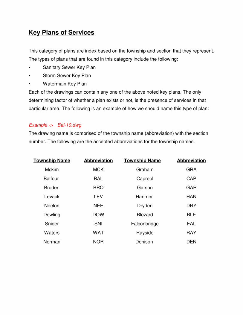
Key Plans of Services
This category of plans are index based on the township and section that they represent.
The types of plans that are found in this category include the following:
• Sanitary Sewer Key Plan
• Storm Sewer Key Plan
• Watermain Key Plan
Each of the drawings can contain any one of the above noted key plans. The only
determining factor of whether a plan exists or not, is the presence of services in that
particular area. The following is an example of how we should name this type of plan:
Example -> Bal-10.dwg
The drawing name is comprised of the township name (abbreviation) with the section
number. The following are the accepted abbreviations for the township names.
Township Name Abbreviation Township Name Abbreviation
Mckim MCK Graham GRA
Balfour BAL Capreol CAP
Broder BRO Garson GAR
Levack LEV Hanmer HAN
Neelon NEE Dryden DRY
Dowling DOW Blezard BLE
Snider SNI Falconbridge FAL
Waters WAT Rayside RAY
Norman NOR Denison DEN
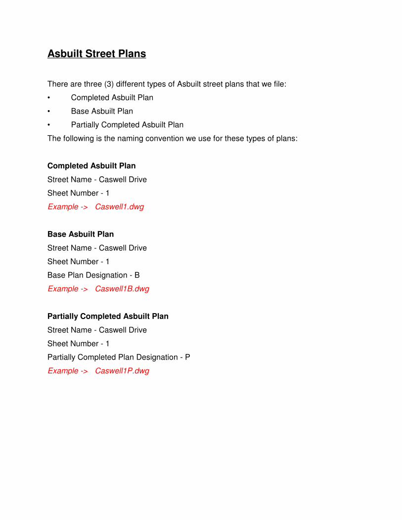
Asbuilt Street Plans
There are three (3) different types of Asbuilt street plans that we file:
• Completed Asbuilt Plan
• Base Asbuilt Plan
• Partially Completed Asbuilt Plan
The following is the naming convention we use for these types of plans:
Completed Asbuilt Plan
Street Name - Caswell Drive
Sheet Number - 1
Example -> Caswell1.dwg
Base Asbuilt Plan
Street Name - Caswell Drive
Sheet Number - 1
Base Plan Designation - B
Example -> Caswell1B.dwg
Partially Completed Asbuilt Plan
Street Name - Caswell Drive
Sheet Number - 1
Partially Completed Plan Designation - P
Example -> Caswell1P.dwg

DIVISION 2
Text Style and Fonts
All of the prototypes we use have predefined text styles. The purpose of predefining the fonts is to
make sure that there is consistency in the drawings we create. The text heights are based on old
"Leroy" standards converted into metric. The majority of the text styles use a "simplex" type font
which provides us a legible letter style with a very small footprint.
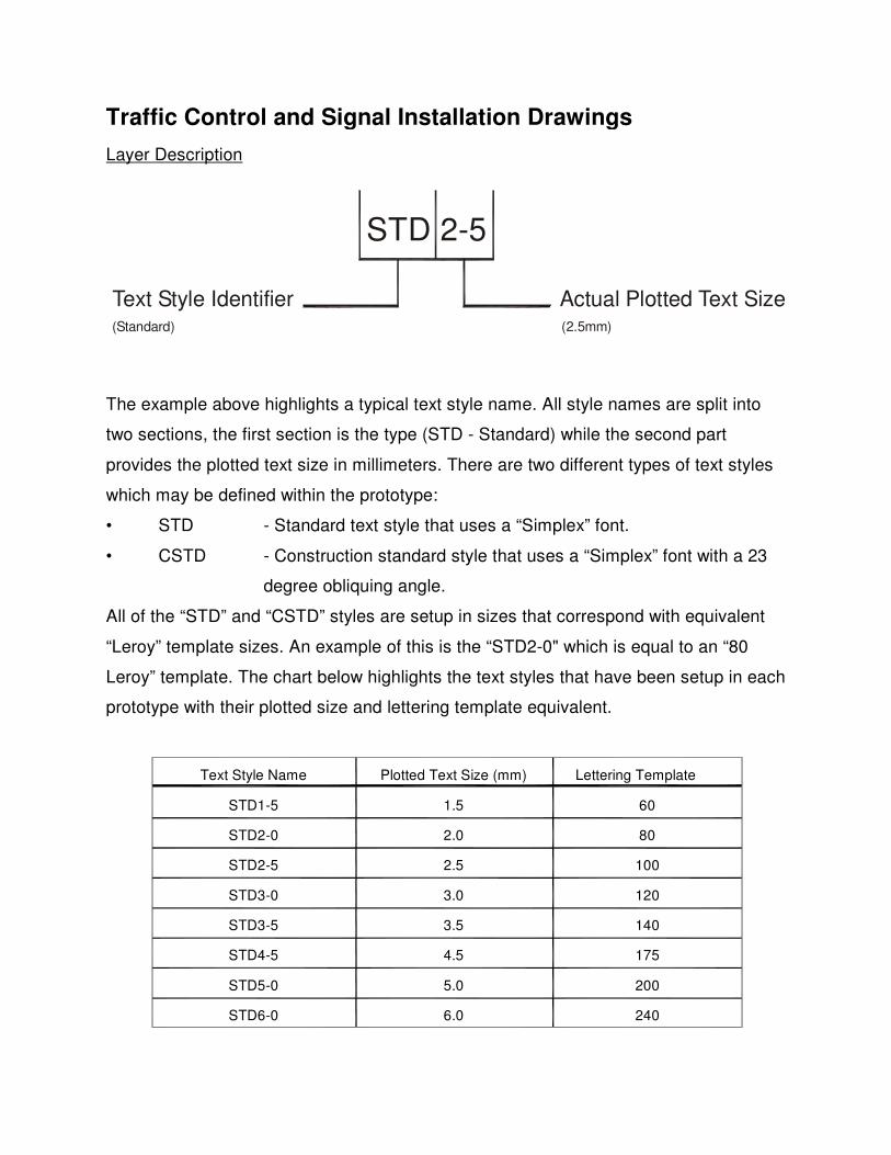
STD 2-5
Actual Plotted Text SizeText Style Identifier
(Standard) (2.5mm)
Traffic Control and Signal Installation Drawings
Layer Description
The example above highlights a typical text style name. All style names are split into
two sections, the first section is the type (STD - Standard) while the second part
provides the plotted text size in millimeters. There are two different types of text styles
which may be defined within the prototype:
• STD - Standard text style that uses a “Simplex” font.
• CSTD - Construction standard style that uses a “Simplex” font with a 23
degree obliquing angle.
All of the “STD” and “CSTD” styles are setup in sizes that correspond with equivalent
“Leroy” template sizes. An example of this is the “STD2-0" which is equal to an “80
Leroy” template. The chart below highlights the text styles that have been setup in each
prototype with their plotted size and lettering template equivalent.
Text Style Name Plotted Text Size (mm) Lettering Template
STD1-5 1.5 60
STD2-0 2.0 80
STD2-5 2.5 100
STD3-0 3.0 120
STD3-5 3.5 140
STD4-5 4.5 175
STD5-0 5.0 200
STD6-0 6.0 240

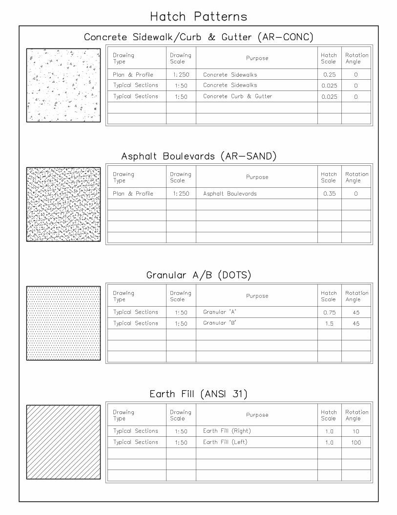
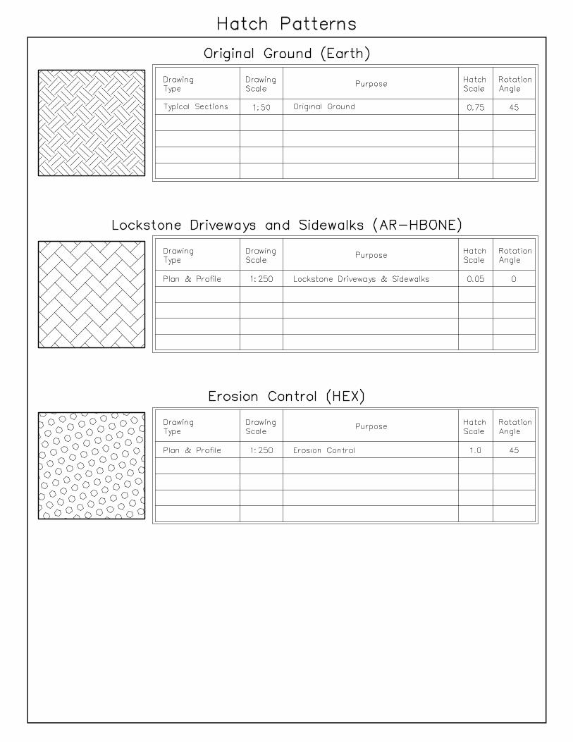
DIVISION 3
Hatching
In the past we have limited the use of hatching within our drawings due to memory limitations on our
computers but that issue is no longer applicable. Nowadays, all of the standard AutoCAD hatch
patterns are available for use in our projects. The hatch patterns defined within the linked document
should be considered the minimum list for use. The other standard AutoCAD hatch patterns can
be used on a project by project basis with the approval of the Control Draftsperson.

DIVISION 4
Scales
Most of the items requiring scales in a drawing have been preset in the various prototypes. The only
exception to this rule is the hatch scale. A recommended hatch scale is indicated in the attached
document but can be manipulated based on the final look required.
Select the document below to review a list of the dimension, linetype and hatch scale values that
have been preset in each prototype.
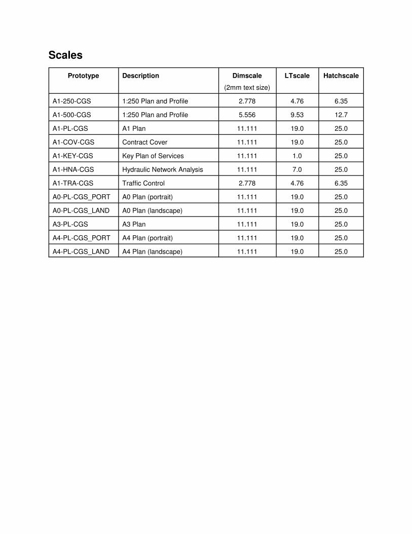
Scales
Prototype Description Dimscale
(2mm text size)
LTscale Hatchscale
A1-250-CGS 1:250 Plan and Profile 2.778 4.76 6.35
A1-500-CGS 1:250 Plan and Profile 5.556 9.53 12.7
A1-PL-CGS A1 Plan 11.111 19.0 25.0
A1-COV-CGS Contract Cover 11.111 19.0 25.0
A1-KEY-CGS Key Plan of Services 11.111 1.0 25.0
A1-HNA-CGS Hydraulic Network Analysis 11.111 7.0 25.0
A1-TRA-CGS Traffic Control 2.778 4.76 6.35
A0-PL-CGS_PORT A0 Plan (portrait) 11.111 19.0 25.0
A0-PL-CGS_LAND A0 Plan (landscape) 11.111 19.0 25.0
A3-PL-CGS A3 Plan 11.111 19.0 25.0
A4-PL-CGS_PORT A4 Plan (portrait) 11.111 19.0 25.0
A4-PL-CGS_LAND A4 Plan (landscape) 11.111 19.0 25.0

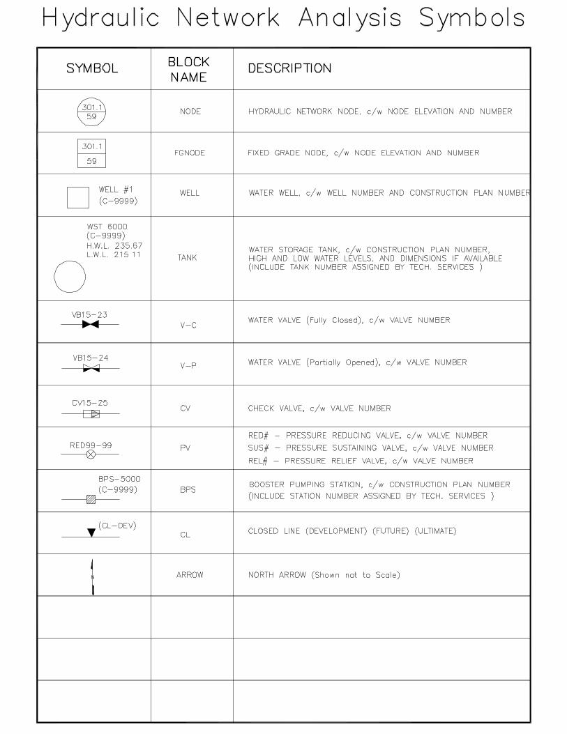
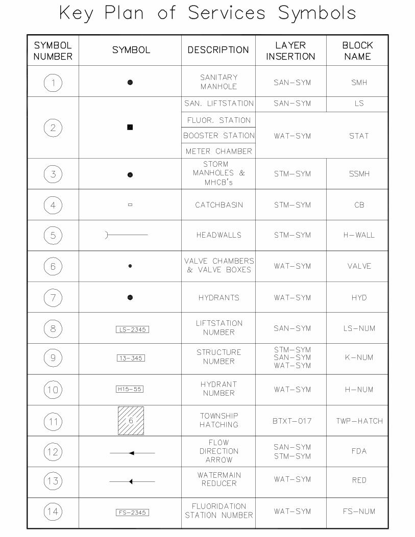
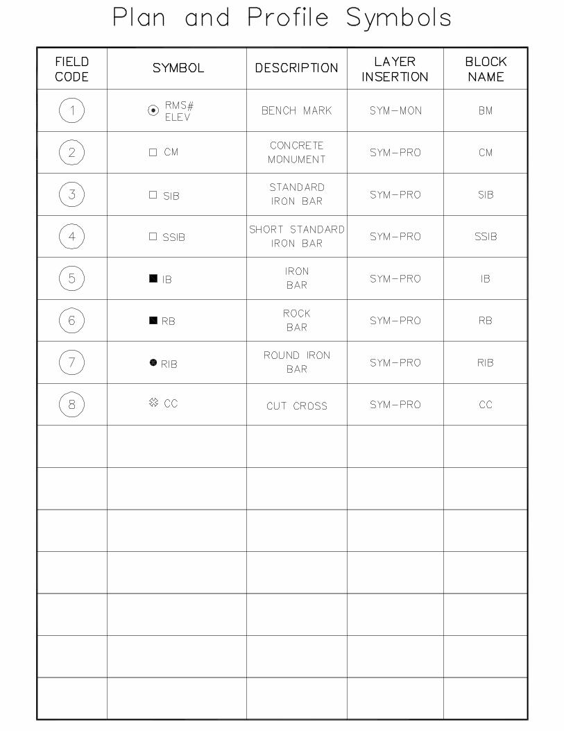
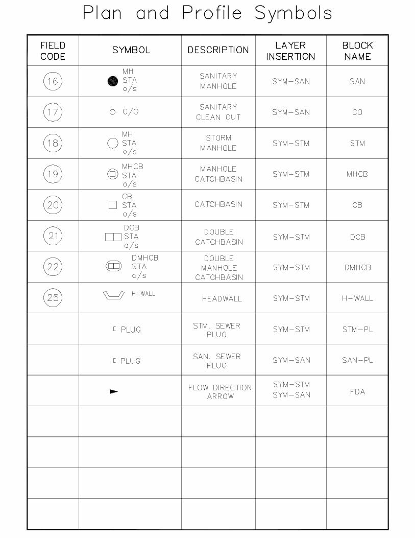
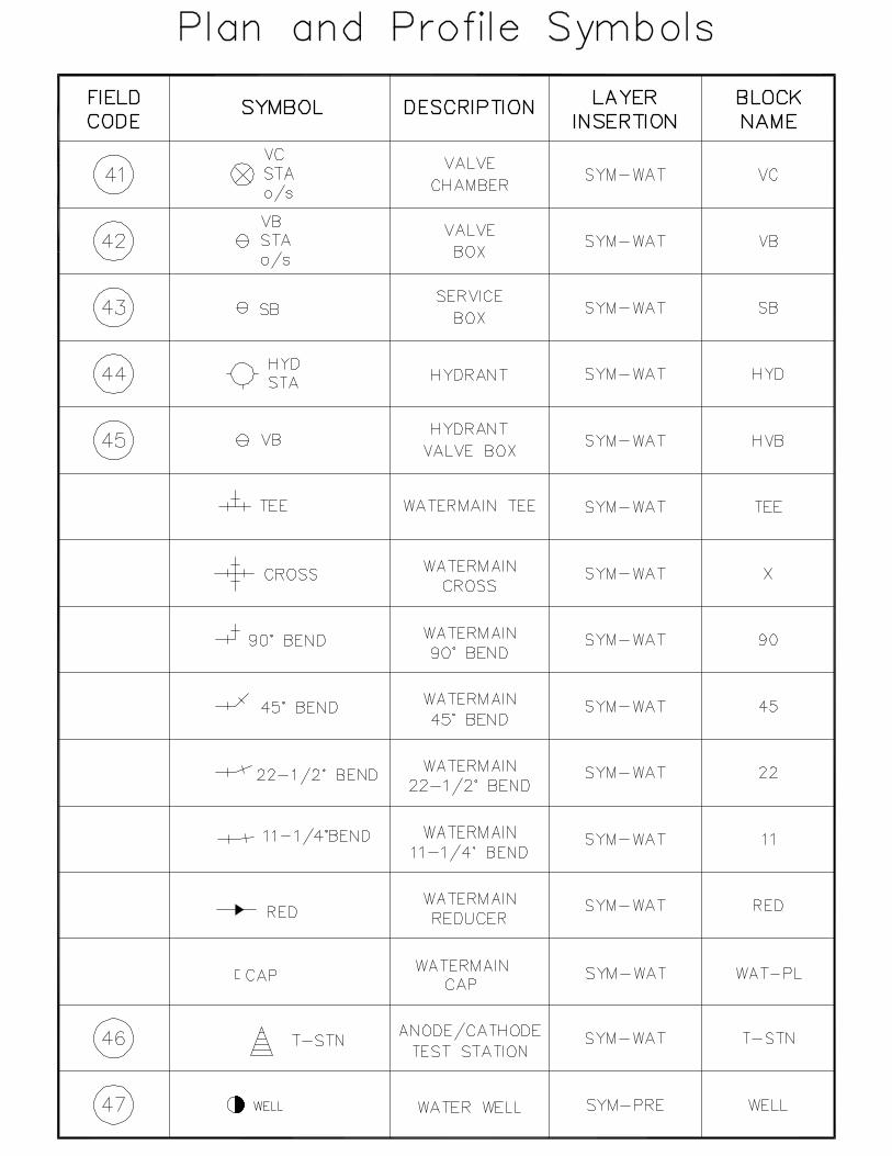
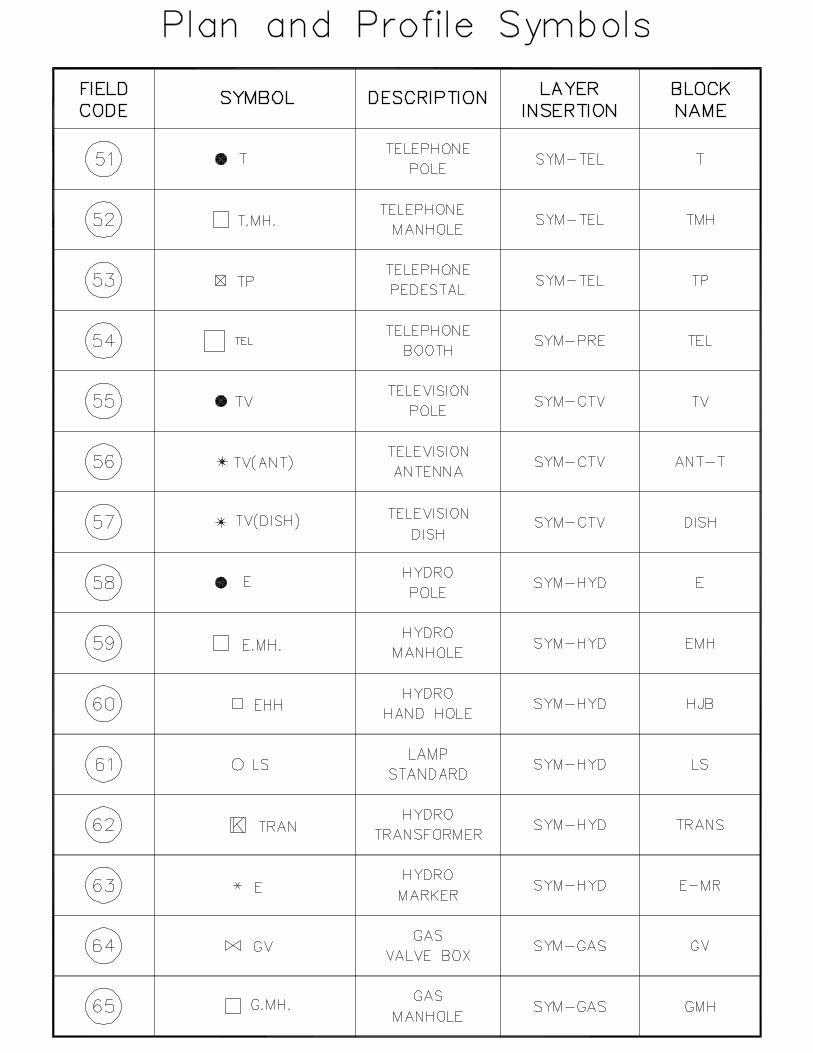
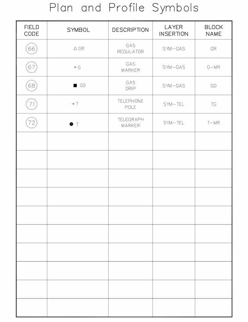
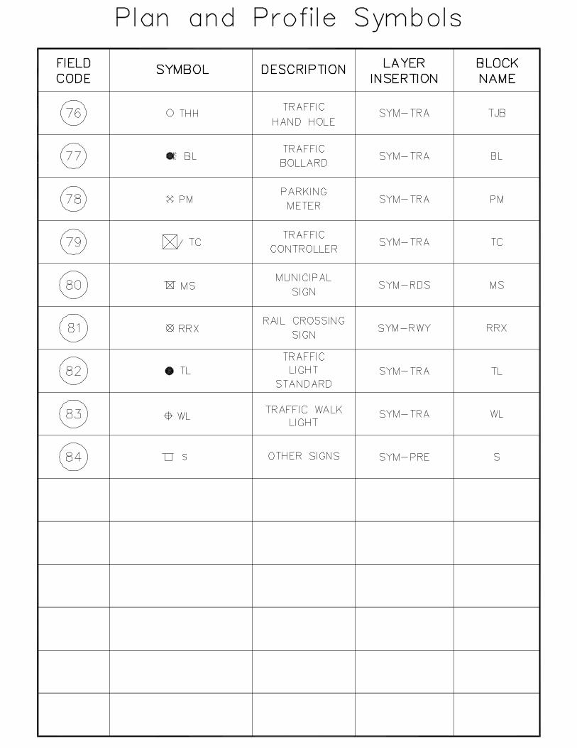
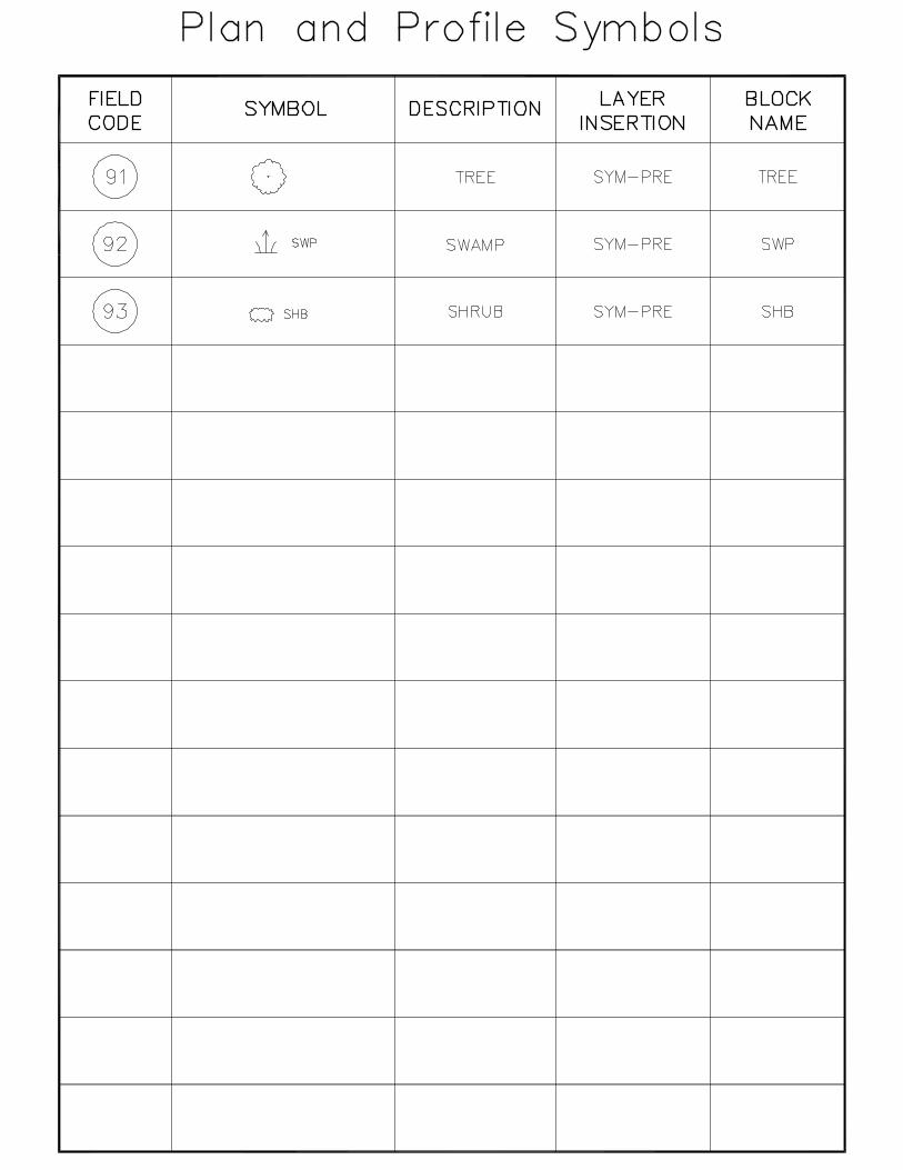
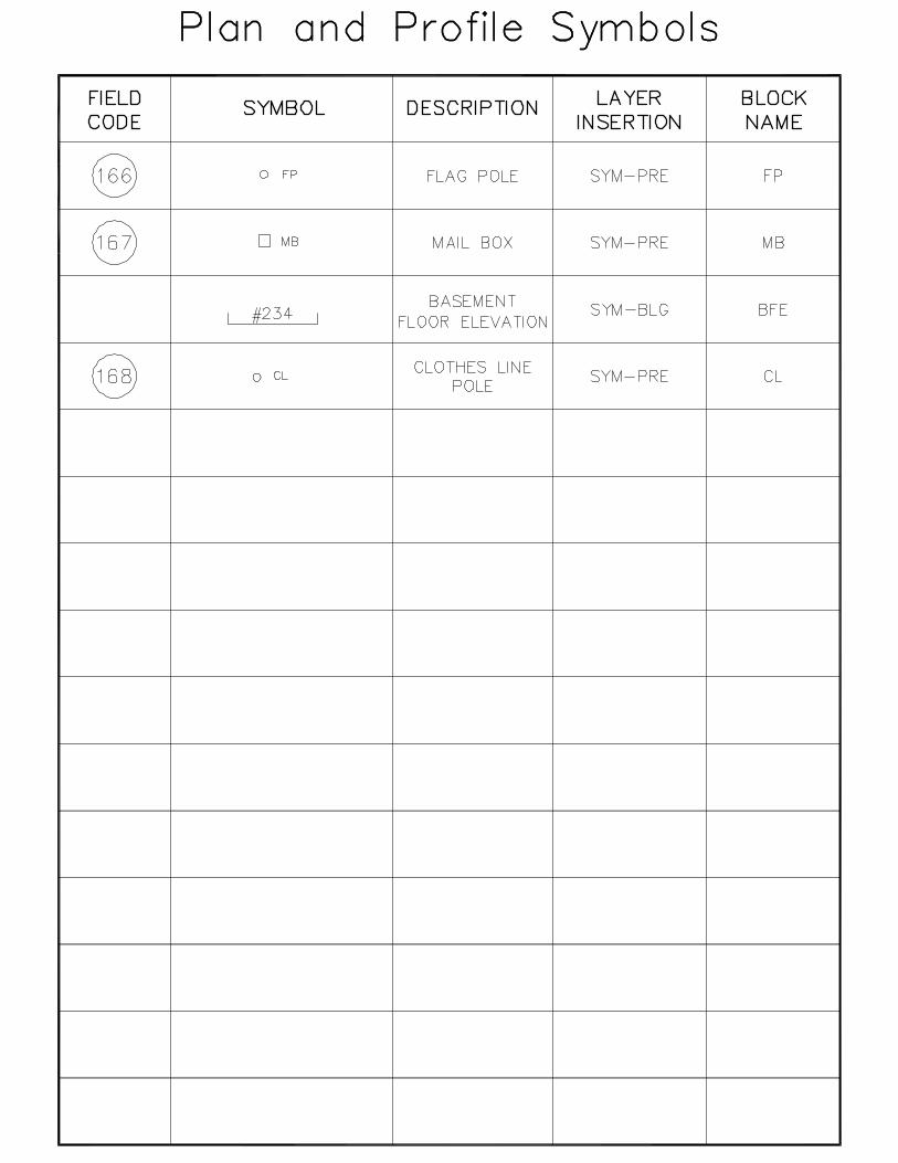
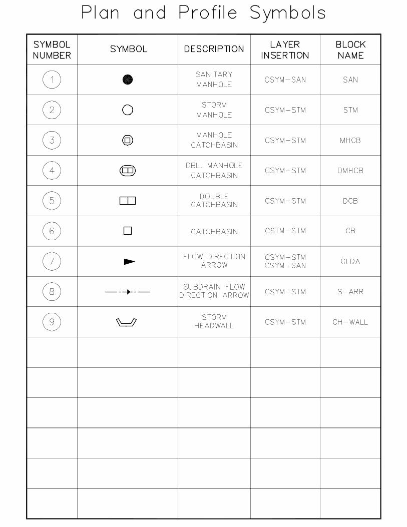
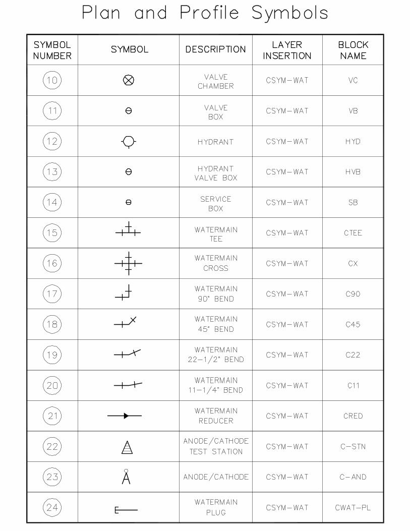
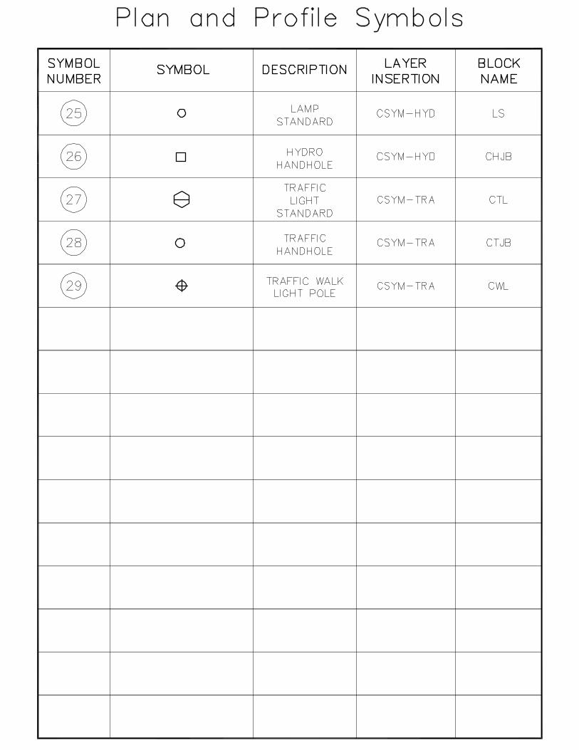
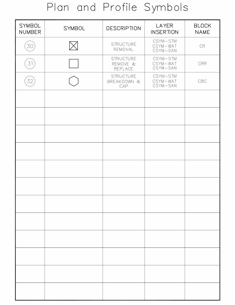
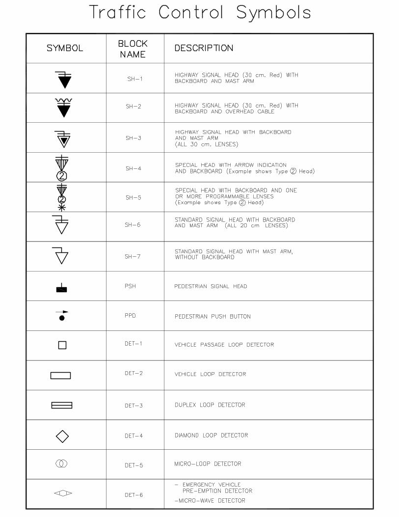
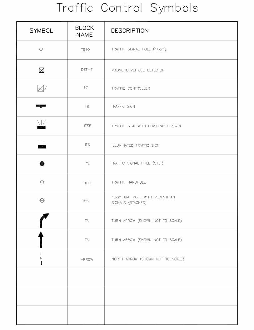
DIVISION 5
Blocks
All of the symbols (blocks) for our drawings are located in the prototypes. They can be inserted into
the drawing by using toolbars and/or pulldown menus. The scales, layers, etc... will be preset during
the insertion process and should not require manipulation for the most part.
Select one of the categories below to see a complete listing of all of the symbols (blocks) defined
within the appropriate drawing.
DIVISION 6
Colour and Pen Codes
This area of the manual has been set aside to discuss the way we have setup pen colours and line
weights within the various prototypes we use. AutoCAD employs one of two (2) different
approaches when establishing plot parameters, namely, "Named Plot Style Tables" or "Colour
Dependant Plot Style Tables". The first approach (named plot style tables) allow you to assign plot
parameters such as lineweight, grayscale, etc.. to individual objects regardless of the colour. The
other approach (colour dependant plot style tables) sets the plot parameters based on the colour
and nothing else. In our environment we have chosen to use colour dependant plot style tables
("CTB files") to control the way our drawings are plotted. This approach, allows us to setup all plot
parameters with the "CTB" file rather than at the plotter.
We currently use one of four different "CTB" files to control how our drawing looks when we plot it.
The following are the colour dependant plot style tables (CTB files) that have been setup:
- Full Size
- Half Size
- Generic Colour
- Key Plan
The "Full Size" CTB file is used when we are plotting any "A0" and "A1" sized drawings. The "Half
Size" CTB file is used when we plot drawings on "A3/B" or "A4/A" size paper. The "Generic Colour"
CTB file is used with colour presentation on all paper sizes. It should be noted that the generic
colour CTB file has all of the pen weights set to 0.25mm and should be adjusted to suit your
requirements. The last CTB file has been setup to handle Key Plans of Services.
Select one of CTB files listed below, to see a complete list of how each table has been setup.
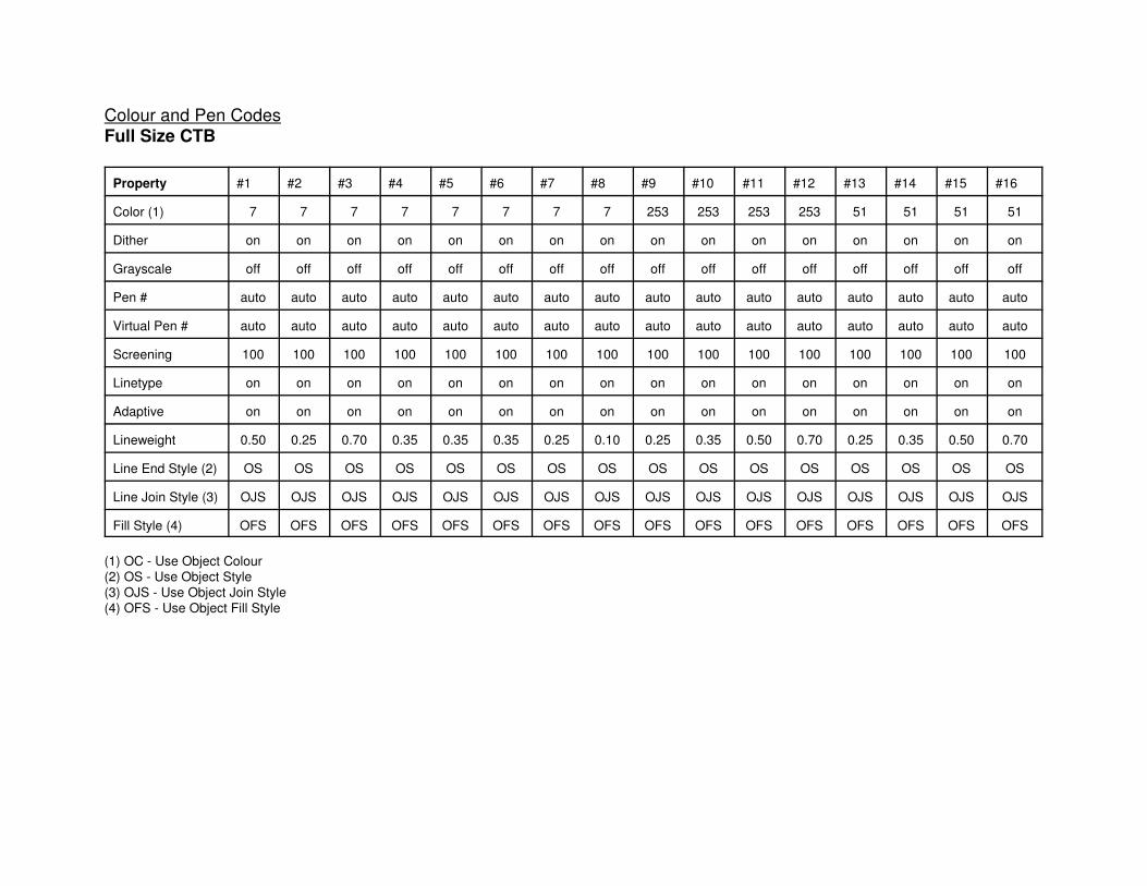
Colour and Pen Codes
Full Size CTB
Property #1 #2 #3 #4 #5 #6 #7 #8 #9 #10 #11 #12 #13 #14 #15 #16
Color (1) 7 7 7 7 7 7 7 7 253 253 253 253 51 51 51 51
Dither on on on on on on on on on on on on on on on on
Grayscale off off off off off off off off off off off off off off off off
Pen # auto auto auto auto auto auto auto auto auto auto auto auto auto auto auto auto
Virtual Pen # auto auto auto auto auto auto auto auto auto auto auto auto auto auto auto auto
Screening 100 100 100 100 100 100 100 100 100 100 100 100 100 100 100 100
Linetype on on on on on on on on on on on on on on on on
Adaptive on on on on on on on on on on on on on on on on
Lineweight 0.50 0.25 0.70 0.35 0.35 0.35 0.25 0.10 0.25 0.35 0.50 0.70 0.25 0.35 0.50 0.70
Line End Style (2) OS OS OS OS OS OS OS OS OS OS OS OS OS OS OS OS
Line Join Style (3) OJS OJS OJS OJS OJS OJS OJS OJS OJS OJS OJS OJS OJS OJS OJS OJS
Fill Style (4) OFS OFS OFS OFS OFS OFS OFS OFS OFS OFS OFS OFS OFS OFS OFS OFS
(1) OC - Use Object Colour
(2) OS - Use Object Style
(3) OJS - Use Object Join Style
(4) OFS - Use Object Fill Style
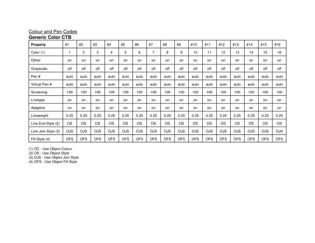
Colour and Pen Codes
Generic Color CTB
Property #1 #2 #3 #4 #5 #6 #7 #8 #9 #10 #11 #12 #13 #14 #15 #16
Color (1) 1 2 3 4 5 6 7 8 9 10 11 12 13 14 15 16
Dither on on on on on on on on on on on on on on on on
Grayscale off off off off off off off off off off off off off off off off
Pen # auto auto auto auto auto auto auto auto auto auto auto auto auto auto auto auto
Virtual Pen # auto auto auto auto auto auto auto auto auto auto auto auto auto auto auto auto
Screening 100 100 100 100 100 100 100 100 100 100 100 100 100 100 100 100
Linetype on on on on on on on on on on on on on on on on
Adaptive on on on on on on on on on on on on on on on on
Lineweight 0.25 0.25 0.25 0.25 0.25 0.25 0.25 0.25 0.25 0.25 0.25 0.25 0.25 0.25 0.25 0.25
Line End Style (2) OS OS OS OS OS OS OS OS OS OS OS OS OS OS OS OS
Line Join Style (3) OJS OJS OJS OJS OJS OJS OJS OJS OJS OJS OJS OJS OJS OJS OJS OJS
Fill Style (4) OFS OFS OFS OFS OFS OFS OFS OFS OFS OFS OFS OFS OFS OFS OFS OFS
(1) OC - Use Object Colour
(2) OS - Use Object Style
(3) OJS - Use Object Join Style
(4) OFS - Use Object Fill Style
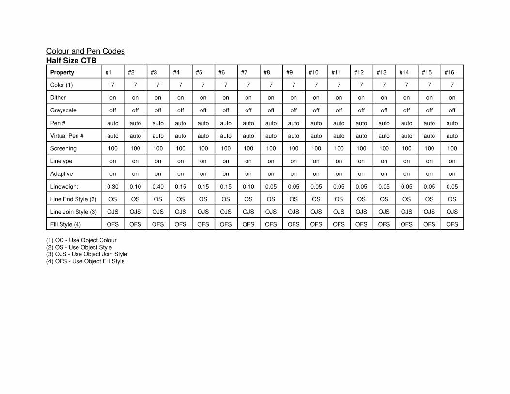
Colour and Pen Codes
Half Size CTB
Property #1 #2 #3 #4 #5 #6 #7 #8 #9 #10 #11 #12 #13 #14 #15 #16
Color (1) 7 7 7 7 7 7 7 7 7 7 7 7 7 7 7 7
Dither on on on on on on on on on on on on on on on on
Grayscale off off off off off off off off off off off off off off off off
Pen # auto auto auto auto auto auto auto auto auto auto auto auto auto auto auto auto
Virtual Pen # auto auto auto auto auto auto auto auto auto auto auto auto auto auto auto auto
Screening 100 100 100 100 100 100 100 100 100 100 100 100 100 100 100 100
Linetype on on on on on on on on on on on on on on on on
Adaptive on on on on on on on on on on on on on on on on
Lineweight 0.30 0.10 0.40 0.15 0.15 0.15 0.10 0.05 0.05 0.05 0.05 0.05 0.05 0.05 0.05 0.05
Line End Style (2) OS OS OS OS OS OS OS OS OS OS OS OS OS OS OS OS
Line Join Style (3) OJS OJS OJS OJS OJS OJS OJS OJS OJS OJS OJS OJS OJS OJS OJS OJS
Fill Style (4) OFS OFS OFS OFS OFS OFS OFS OFS OFS OFS OFS OFS OFS OFS OFS OFS
(1) OC - Use Object Colour
(2) OS - Use Object Style
(3) OJS - Use Object Join Style
(4) OFS - Use Object Fill Style
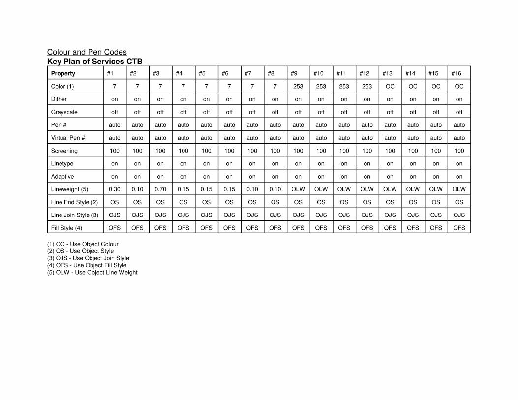
Colour and Pen Codes
Key Plan of Services CTB
Property #1 #2 #3 #4 #5 #6 #7 #8 #9 #10 #11 #12 #13 #14 #15 #16
Color (1) 7 7 7 7 7 7 7 7 253 253 253 253 OC OC OC OC
Dither on on on on on on on on on on on on on on on on
Grayscale off off off off off off off off off off off off off off off off
Pen # auto auto auto auto auto auto auto auto auto auto auto auto auto auto auto auto
Virtual Pen # auto auto auto auto auto auto auto auto auto auto auto auto auto auto auto auto
Screening 100 100 100 100 100 100 100 100 100 100 100 100 100 100 100 100
Linetype on on on on on on on on on on on on on on on on
Adaptive on on on on on on on on on on on on on on on on
Lineweight (5) 0.30 0.10 0.70 0.15 0.15 0.15 0.10 0.10 OLW OLW OLW OLW OLW OLW OLW OLW
Line End Style (2) OS OS OS OS OS OS OS OS OS OS OS OS OS OS OS OS
Line Join Style (3) OJS OJS OJS OJS OJS OJS OJS OJS OJS OJS OJS OJS OJS OJS OJS OJS
Fill Style (4) OFS OFS OFS OFS OFS OFS OFS OFS OFS OFS OFS OFS OFS OFS OFS OFS
(1) OC - Use Object Colour
(2) OS - Use Object Style
(3) OJS - Use Object Join Style
(4) OFS - Use Object Fill Style
(5) OLW - Use Object Line Weight

DIVISION 7
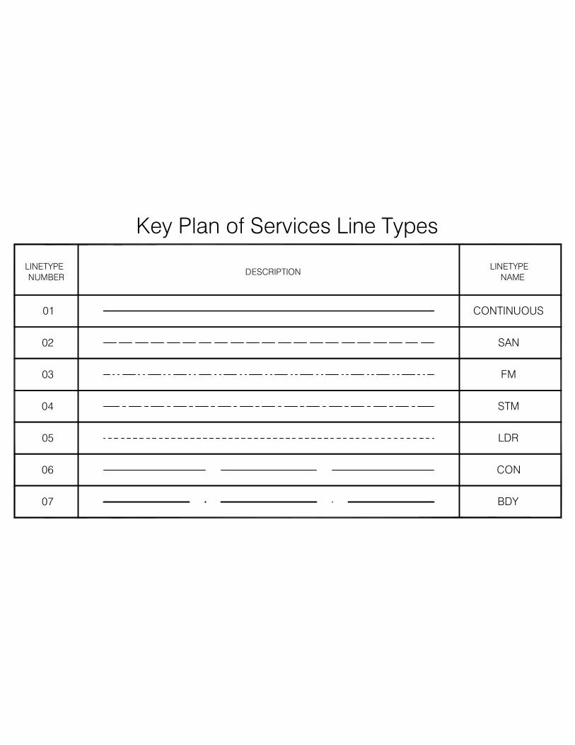
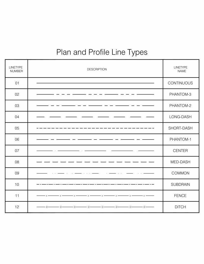
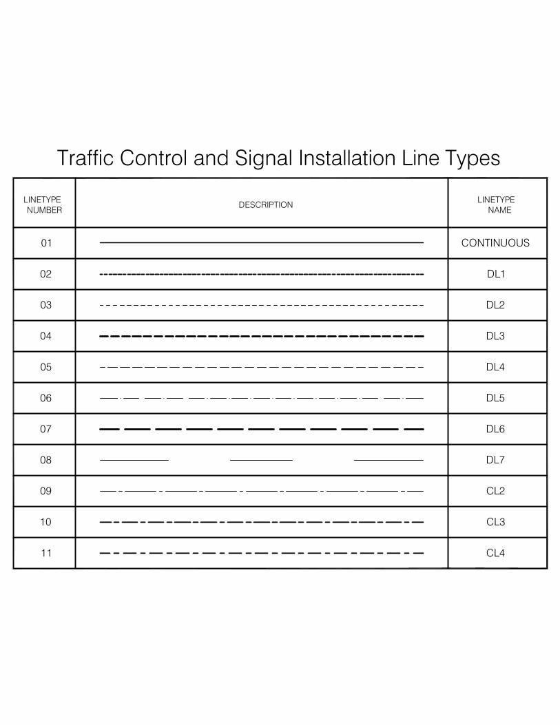
Linetypes
We are presently using the standard AutoCAD linetypes in the majority of the drawing prototypes we
use. The only exceptions to this rule are the Plan & Profile, Key, HNA and Traffic Control Plans
which have customized line pattern files established in them. These prototypes have all the custom
linetypes pre-loaded with linetype scales preset.
Select one of the plan types listed below, to view a chart highlighting the custom linetypes.
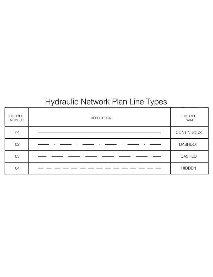
LINETYPE
NUMBER
01
02
03
DESCRIPTION
CONTINUOUS
DASHED
DASHDOT
LINETYPE
NAME
04 HIDDEN
Hydraulic Network Plan Line Types
05
06
07
LINETYPE
NUMBER
01
02
03
04
BDY
CON
LDR
DESCRIPTION
CONTINUOUS
STM
FM
SAN
LINETYPE
NAME
Key Plan of Services Line Types
10 SUBDRAIN
09 COMMON
08 MED-DASH
07 CENTER
06 PHANTOM-1
05 SHORT-DASH
04 LONG-DASH
03 PHANTOM-2
02 PHANTOM-3
CONTINUOUS01
NUMBER NAME
LINETYPELINETYPEDESCRIPTION
12 D D D D D D D D
x x x x x x x x11
DITCH
FENCE
Plan and Profile Line Types
DESCRIPTION
11
10
09
08
NUMBER
LINETYPE
05
06
07
04
03
02
01
CL4
CL3
CL2
DL7
CONTINUOUS
DL4
DL5
DL6
DL3
DL2
DL1
NAME
LINETYPE
Traffic Control and Signal Installation Line Types
DIVISION 8
Layering Conventions
We are presently utilizing four layering conventions for the various drawings we complete on our
computer systems. Although there are subtle differences in all of the layering conventions, they all
follow the same basic rules. All of the layer names are made up of a three or four character category
followed by a three number or letter identifier. All drawings completed on the computer systems
should follow these basic rules or derivatives of them.
Select one of the Layer Conventions listed below to access a complete listing of all predefined
layers.
WAT - 017
Layer IdentifierLayer Category
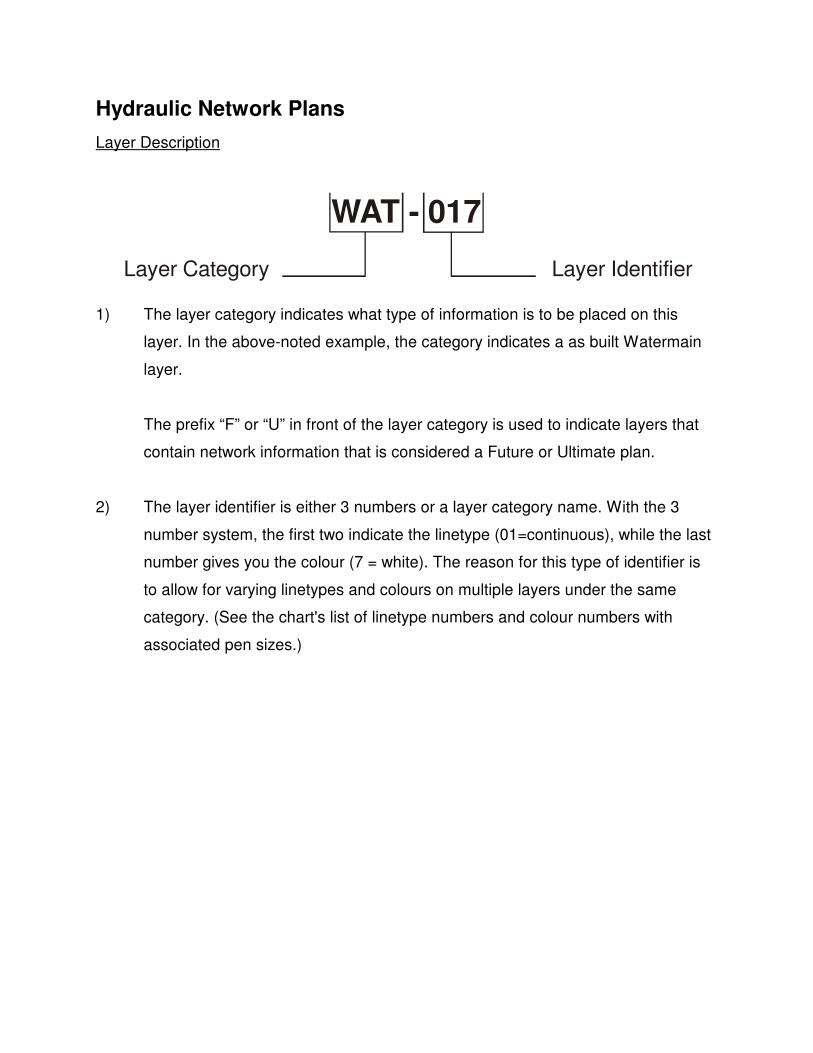
Hydraulic Network Plans
Layer Description
1) The layer category indicates what type of information is to be placed on this
layer. In the above-noted example, the category indicates a as built Watermain
layer.
The prefix “F” or “U” in front of the layer category is used to indicate layers that
contain network information that is considered a Future or Ultimate plan.
2) The layer identifier is either 3 numbers or a layer category name. With the 3
number system, the first two indicate the linetype (01=continuous), while the last
number gives you the colour (7 = white). The reason for this type of identifier is
to allow for varying linetypes and colours on multiple layers under the same
category. (See the chart's list of linetype numbers and colour numbers with
associated pen sizes.)
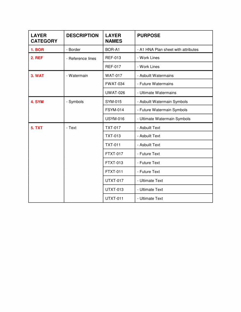
LAYER
CATEGORY
DESCRIPTION LAYER
NAMES
PURPOSE
1. BOR - Border BOR-A1 - A1 HNA Plan sheet with attributes
2. REF - Reference lines REF-013 - Work Lines
REF-017 - Work Lines
3. WAT - Watermain WAT-017 - Asbuilt Watermains
FWAT-034 - Future Watermains
UWAT-026 - Ultimate Watermains
4. SYM - Symbols SYM-015 - Asbuilt Watermain Symbols
FSYM-014 - Future Watermain Symbols
USYM-016 - Ultimate Watermain Symbols
5. TXT - Text TXT-017 - Asbuilt Text
TXT-013 - Asbuilt Text
TXT-011 - Asbuilt Text
FTXT-017 - Future Text
FTXT-013 - Future Text
FTXT-011 - Future Text
UTXT-017 - Ultimate Text
UTXT-013 - Ultimate Text
UTXT-011 - Ultimate Text
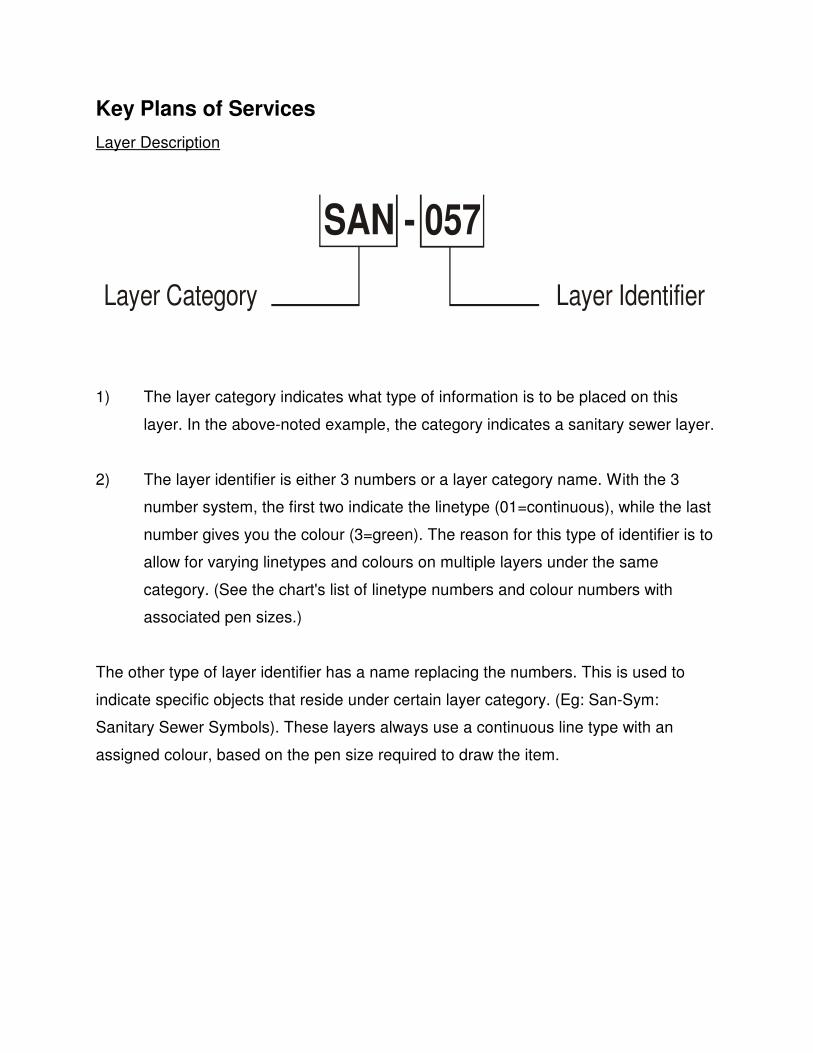
SAN - 057
Layer IdentifierLayer Category
Key Plans of Services
Layer Description
1) The layer category indicates what type of information is to be placed on this
layer. In the above-noted example, the category indicates a sanitary sewer layer.
2) The layer identifier is either 3 numbers or a layer category name. With the 3
number system, the first two indicate the linetype (01=continuous), while the last
number gives you the colour (3=green). The reason for this type of identifier is to
allow for varying linetypes and colours on multiple layers under the same
category. (See the chart's list of linetype numbers and colour numbers with
associated pen sizes.)
The other type of layer identifier has a name replacing the numbers. This is used to
indicate specific objects that reside under certain layer category. (Eg: San-Sym:
Sanitary Sewer Symbols). These layers always use a continuous line type with an
assigned colour, based on the pen size required to draw the item.
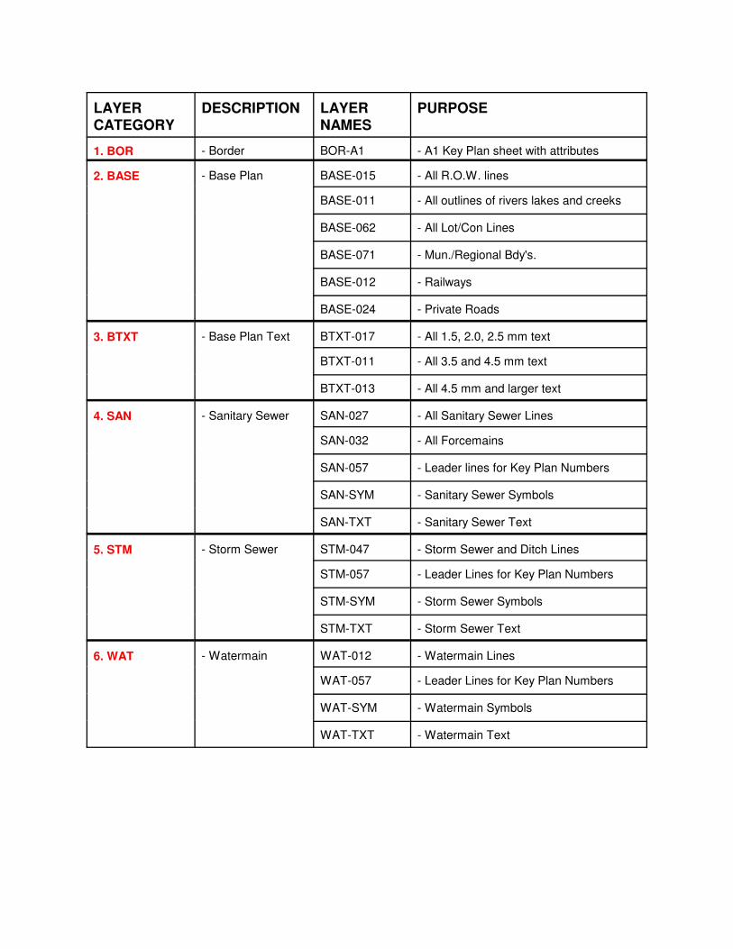
LAYER
CATEGORY
DESCRIPTION LAYER
NAMES
PURPOSE
1. BOR - Border BOR-A1 - A1 Key Plan sheet with attributes
2. BASE - Base Plan BASE-015 - All R.O.W. lines
BASE-011 - All outlines of rivers lakes and creeks
BASE-062 - All Lot/Con Lines
BASE-071 - Mun./Regional Bdy's.
BASE-012 - Railways
BASE-024 - Private Roads
3. BTXT - Base Plan Text BTXT-017 - All 1.5, 2.0, 2.5 mm text
BTXT-011 - All 3.5 and 4.5 mm text
BTXT-013 - All 4.5 mm and larger text
4. SAN - Sanitary Sewer SAN-027 - All Sanitary Sewer Lines
SAN-032 - All Forcemains
SAN-057 - Leader lines for Key Plan Numbers
SAN-SYM - Sanitary Sewer Symbols
SAN-TXT - Sanitary Sewer Text
5. STM - Storm Sewer STM-047 - Storm Sewer and Ditch Lines
STM-057 - Leader Lines for Key Plan Numbers
STM-SYM - Storm Sewer Symbols
STM-TXT - Storm Sewer Text
6. WAT - Watermain WAT-012 - Watermain Lines
WAT-057 - Leader Lines for Key Plan Numbers
WAT-SYM - Watermain Symbols
WAT-TXT - Watermain Text
TXT - 013
Layer IdentifierLayer Category
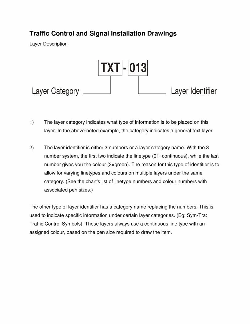
Traffic Control and Signal Installation Drawings
Layer Description
1) The layer category indicates what type of information is to be placed on this
layer. In the above-noted example, the category indicates a general text layer.
2) The layer identifier is either 3 numbers or a layer category name. With the 3
number system, the first two indicate the linetype (01=continuous), while the last
number gives you the colour (3=green). The reason for this type of identifier is to
allow for varying linetypes and colours on multiple layers under the same
category. (See the chart's list of linetype numbers and colour numbers with
associated pen sizes.)
The other type of layer identifier has a category name replacing the numbers. This is
used to indicate specific information under certain layer categories. (Eg: Sym-Tra:
Traffic Control Symbols). These layers always use a continuous line type with an
assigned colour, based on the pen size required to draw the item.
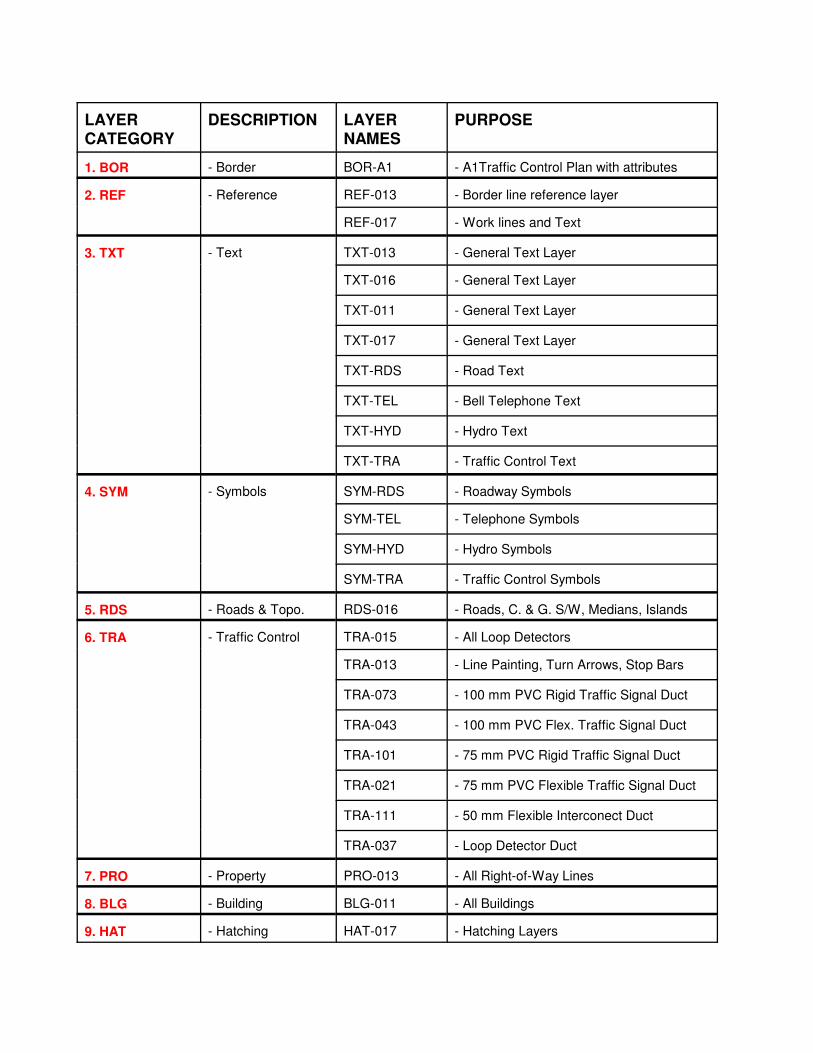
LAYER
CATEGORY
DESCRIPTION LAYER
NAMES
PURPOSE
1. BOR - Border BOR-A1 - A1Traffic Control Plan with attributes
2. REF - Reference REF-013 - Border line reference layer
REF-017 - Work lines and Text
3. TXT - Text TXT-013 - General Text Layer
TXT-016 - General Text Layer
TXT-011 - General Text Layer
TXT-017 - General Text Layer
TXT-RDS - Road Text
TXT-TEL - Bell Telephone Text
TXT-HYD - Hydro Text
TXT-TRA - Traffic Control Text
4. SYM - Symbols SYM-RDS - Roadway Symbols
SYM-TEL - Telephone Symbols
SYM-HYD - Hydro Symbols
SYM-TRA - Traffic Control Symbols
5. RDS - Roads & Topo. RDS-016 - Roads, C. & G. S/W, Medians, Islands
6. TRA - Traffic Control TRA-015 - All Loop Detectors
TRA-013 - Line Painting, Turn Arrows, Stop Bars
TRA-073 - 100 mm PVC Rigid Traffic Signal Duct
TRA-043 - 100 mm PVC Flex. Traffic Signal Duct
TRA-101 - 75 mm PVC Rigid Traffic Signal Duct
TRA-021 - 75 mm PVC Flexible Traffic Signal Duct
TRA-111 - 50 mm Flexible Interconect Duct
TRA-037 - Loop Detector Duct
7. PRO - Property PRO-013 - All Right-of-Way Lines
8. BLG - Building BLG-011 - All Buildings
9. HAT - Hatching HAT-017 - Hatching Layers
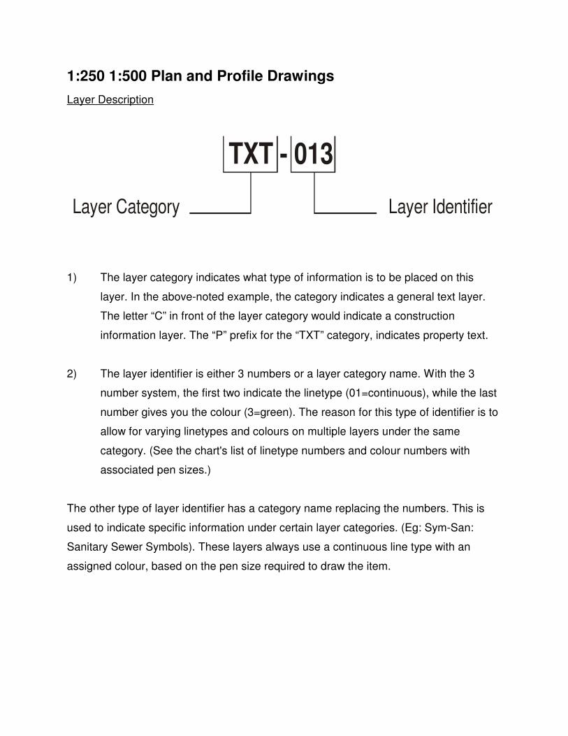
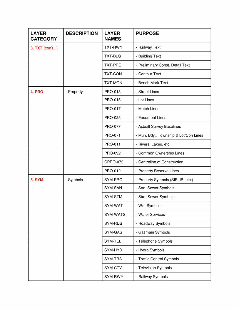
TXT - 013
Layer IdentifierLayer Category
1:250 1:500 Plan and Profile Drawings
Layer Description
1) The layer category indicates what type of information is to be placed on this
layer. In the above-noted example, the category indicates a general text layer.
The letter “C” in front of the layer category would indicate a construction
information layer. The “P” prefix for the “TXT” category, indicates property text.
2) The layer identifier is either 3 numbers or a layer category name. With the 3
number system, the first two indicate the linetype (01=continuous), while the last
number gives you the colour (3=green). The reason for this type of identifier is to
allow for varying linetypes and colours on multiple layers under the same
category. (See the chart's list of linetype numbers and colour numbers with
associated pen sizes.)
The other type of layer identifier has a category name replacing the numbers. This is
used to indicate specific information under certain layer categories. (Eg: Sym-San:
Sanitary Sewer Symbols). These layers always use a continuous line type with an
assigned colour, based on the pen size required to draw the item.
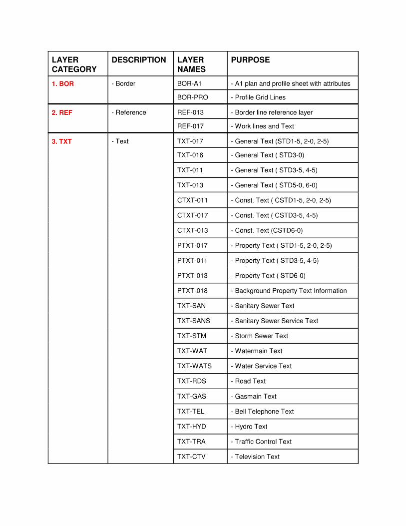
LAYER
CATEGORY
DESCRIPTION LAYER
NAMES
PURPOSE
1. BOR - Border BOR-A1 - A1 plan and profile sheet with attributes
BOR-PRO - Profile Grid Lines
2. REF - Reference REF-013 - Border line reference layer
REF-017 - Work lines and Text
3. TXT - Text TXT-017 - General Text (STD1-5, 2-0, 2-5)
TXT-016 - General Text ( STD3-0)
TXT-011 - General Text ( STD3-5, 4-5)
TXT-013 - General Text ( STD5-0, 6-0)
CTXT-011 - Const. Text ( CSTD1-5, 2-0, 2-5)
CTXT-017 - Const. Text ( CSTD3-5, 4-5)
CTXT-013 - Const. Text (CSTD6-0)
PTXT-017 - Property Text ( STD1-5, 2-0, 2-5)
PTXT-011 - Property Text ( STD3-5, 4-5)
PTXT-013 - Property Text ( STD6-0)
PTXT-018 - Background Property Text Information
TXT-SAN - Sanitary Sewer Text
TXT-SANS - Sanitary Sewer Service Text
TXT-STM - Storm Sewer Text
TXT-WAT - Watermain Text
TXT-WATS - Water Service Text
TXT-RDS - Road Text
TXT-GAS - Gasmain Text
TXT-TEL - Bell Telephone Text
TXT-HYD - Hydro Text
TXT-TRA - Traffic Control Text
TXT-CTV - Television Text
LAYER
CATEGORY
DESCRIPTION LAYER
NAMES
PURPOSE
3. TXT (con’t...) TXT-RWY - Railway Text
TXT-BLG - Building Text
TXT-PRE - Preliminary Const. Detail Text
TXT-CON - Contour Text
TXT-MON - Bench Mark Text
4. PRO - Property PRO-013 - Street Lines
PRO-015 - Lot Lines
PRO-017 - Match Lines
PRO-025 - Easement Lines
PRO-077 - Asbuilt Survey Baselines
PRO-071 - Mun. Bdy., Township & Lot/Con Lines
PRO-011 - Rivers, Lakes, etc.
PRO-092 - Common Ownership Lines
CPRO-072 - Centreline of Construction
PRO-012 - Property Reserve Lines
5. SYM - Symbols SYM-PRO - Property Symbols (SIB, IB, etc.)
SYM-SAN - San. Sewer Symbols
SYM-STM - Stm. Sewer Symbols
SYM-WAT - Wm Symbols
SYM-WATS - Water Services
SYM-RDS - Roadway Symbols
SYM-GAS - Gasmain Symbols
SYM-TEL - Telephone Symbols
SYM-HYD - Hydro Symbols
SYM-TRA - Traffic Control Symbols
SYM-CTV - Television Symbols
SYM-RWY - Railway Symbols
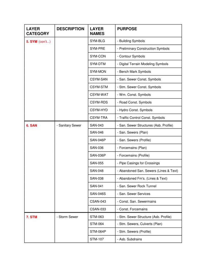
LAYER
CATEGORY
DESCRIPTION LAYER
NAMES
PURPOSE
5. SYM (con’t...) SYM-BLG - Building Symbols
SYM-PRE - Preliminary Construction Symbols
SYM-CON - Contour Symbols
SYM-DTM - Digital Terrain Modeling Symbols
SYM-MON - Bench Mark Symbols
CSYM-SAN - San. Sewer Const. Symbols
CSYM-STM - Stm. Sewer Const. Symbols
CSYM-WAT - Wm. Const. Symbols
CSYM-RDS - Road Const. Symbols
CSYM-HYD - Hydro Const. Symbols
CSYM-TRA - Traffic Control Const. Symbols
6. SAN - Sanitary Sewer SAN-043 - San. Sewer Structures (Asb. Profile)
SAN-046 - San. Sewers (Plan)
SAN-046P - San. Sewers (Profile)
SAN-036 - Forcemains (Plan)
SAN-036P - Forcemains (Profile)
SAN-055 - Pipe Casings for Crossings
SAN-048 - Abandoned San. Sewers (Lines & Text)
SAN-038 - Abandoned Fm's. (Lines & Text)
SAN-041 - San. Sewer Rock Tunnel
SAN-046S - San. Sewer Services
CSAN-043 - Const. San. Sewermains
CSAN-033 - Const. Forcemains
7. STM - Storm Sewer STM-063 - Stm. Sewer Structure (Asb. Profile)
STM-064 - Stm. Sewers, Culverts (Plan)
STM-064P - Stm. Sewers (Profile)
STM-107 - Asb. Subdrains
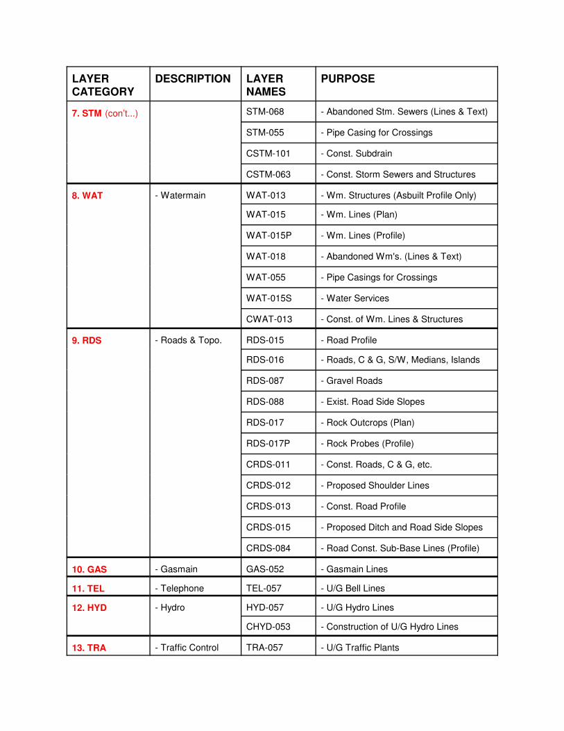
LAYER
CATEGORY
DESCRIPTION LAYER
NAMES
PURPOSE
7. STM (con’t...) STM-068 - Abandoned Stm. Sewers (Lines & Text)
STM-055 - Pipe Casing for Crossings
CSTM-101 - Const. Subdrain
CSTM-063 - Const. Storm Sewers and Structures
8. WAT - Watermain WAT-013 - Wm. Structures (Asbuilt Profile Only)
WAT-015 - Wm. Lines (Plan)
WAT-015P - Wm. Lines (Profile)
WAT-018 - Abandoned Wm's. (Lines & Text)
WAT-055 - Pipe Casings for Crossings
WAT-015S - Water Services
CWAT-013 - Const. of Wm. Lines & Structures
9. RDS - Roads & Topo. RDS-015 - Road Profile
RDS-016 - Roads, C & G, S/W, Medians, Islands
RDS-087 - Gravel Roads
RDS-088 - Exist. Road Side Slopes
RDS-017 - Rock Outcrops (Plan)
RDS-017P - Rock Probes (Profile)
CRDS-011 - Const. Roads, C & G, etc.
CRDS-012 - Proposed Shoulder Lines
CRDS-013 - Const. Road Profile
CRDS-015 - Proposed Ditch and Road Side Slopes
CRDS-084 - Road Const. Sub-Base Lines (Profile)
10. GAS - Gasmain GAS-052 - Gasmain Lines
11. TEL - Telephone TEL-057 - U/G Bell Lines
12. HYD - Hydro HYD-057 - U/G Hydro Lines
CHYD-053 - Construction of U/G Hydro Lines
13. TRA - Traffic Control TRA-057 - U/G Traffic Plants
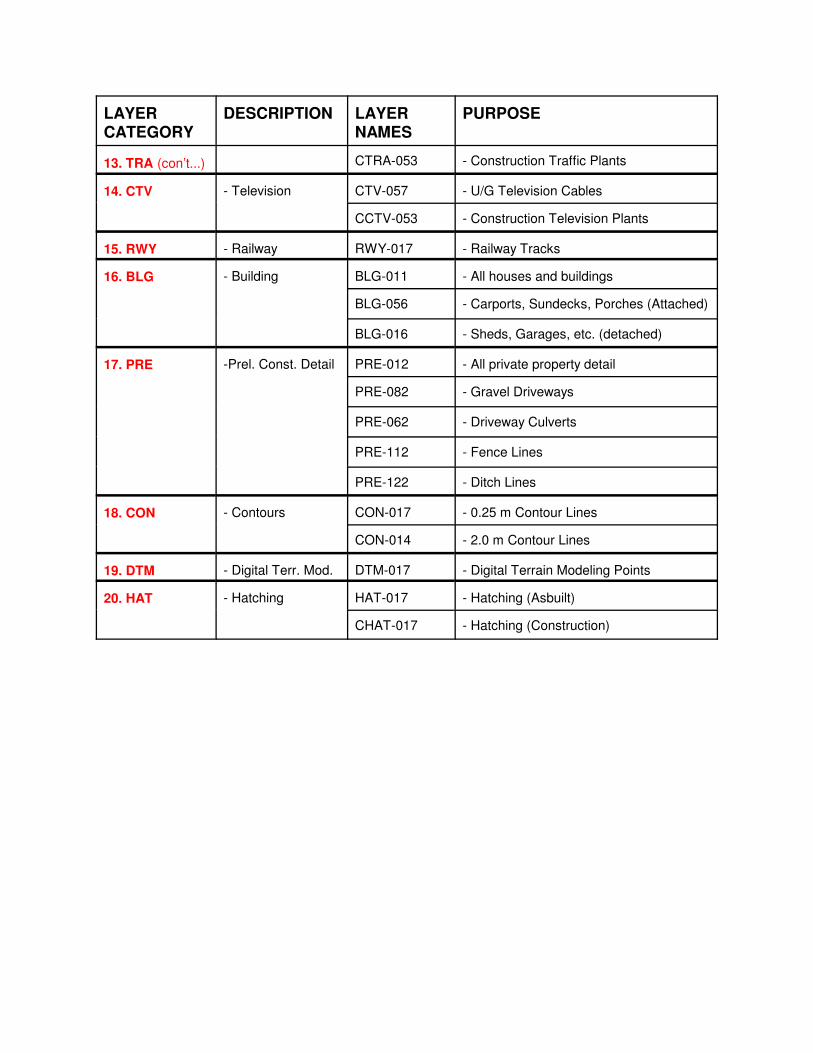
LAYER
CATEGORY
DESCRIPTION LAYER
NAMES
PURPOSE
13. TRA (con’t...) CTRA-053 - Construction Traffic Plants
14. CTV - Television CTV-057 - U/G Television Cables
CCTV-053 - Construction Television Plants
15. RWY - Railway RWY-017 - Railway Tracks
16. BLG - Building BLG-011 - All houses and buildings
BLG-056 - Carports, Sundecks, Porches (Attached)
BLG-016 - Sheds, Garages, etc. (detached)
17. PRE -Prel. Const. Detail PRE-012 - All private property detail
PRE-082 - Gravel Driveways
PRE-062 - Driveway Culverts
PRE-112 - Fence Lines
PRE-122 - Ditch Lines
18. CON - Contours CON-017 - 0.25 m Contour Lines
CON-014 - 2.0 m Contour Lines
19. DTM - Digital Terr. Mod. DTM-017 - Digital Terrain Modeling Points
20. HAT - Hatching HAT-017 - Hatching (Asbuilt)
CHAT-017 - Hatching (Construction)


![Triton Drafting Standards Manual[1]](https://img.pdfslide.us/doc/110x75/543ba14bafaf9f4a578b4a06/triton-drafting-standards-manual1.jpg)