Embed Size (px)
Citation preview

The Government of The Hong Kong Special Administrative Region
Drafting Specifications for Engineering Survey
(to be used in conjunction with CAD Standard for Works Projects)
Agriculture, Fisheries and Conservation Department Civil Engineering and Development Department Drainage Services Department Highways Department Housing Department Water Supplies Department
Rev. 3.0/November 2014
i
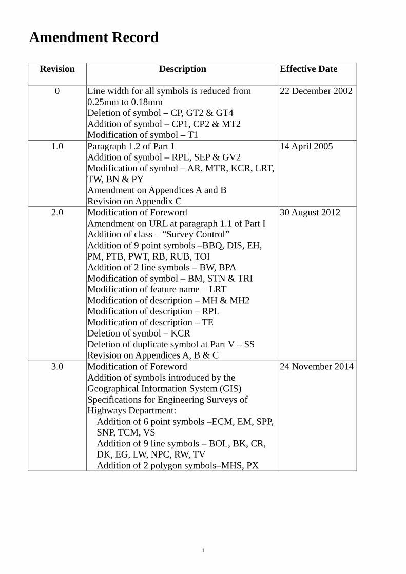
Amendment Record
Revision
Description Effective Date
0 Line width for all symbols is reduced from 0.25mm to 0.18mm Deletion of symbol – CP, GT2 & GT4 Addition of symbol – CP1, CP2 & MT2 Modification of symbol – T1
22 December 2002
1.0 Paragraph 1.2 of Part I Addition of symbol – RPL, SEP & GV2 Modification of symbol – AR, MTR, KCR, LRT, TW, BN & PY Amendment on Appendices A and B Revision on Appendix C
14 April 2005
2.0 Modification of Foreword Amendment on URL at paragraph 1.1 of Part I Addition of class – “Survey Control” Addition of 9 point symbols –BBQ, DIS, EH, PM, PTB, PWT, RB, RUB, TOI Addition of 2 line symbols – BW, BPA Modification of symbol – BM, STN & TRI Modification of feature name – LRT Modification of description – MH & MH2 Modification of description – RPL Modification of description – TE Deletion of symbol – KCR Deletion of duplicate symbol at Part V – SS Revision on Appendices A, B & C
30 August 2012
3.0 Modification of Foreword Addition of symbols introduced by the Geographical Information System (GIS) Specifications for Engineering Surveys of Highways Department:
Addition of 6 point symbols –ECM, EM, SPP, SNP, TCM, VS Addition of 9 line symbols – BOL, BK, CR, DK, EG, LW, NPC, RW, TV Addition of 2 polygon symbols–MHS, PX
24 November 2014
ii
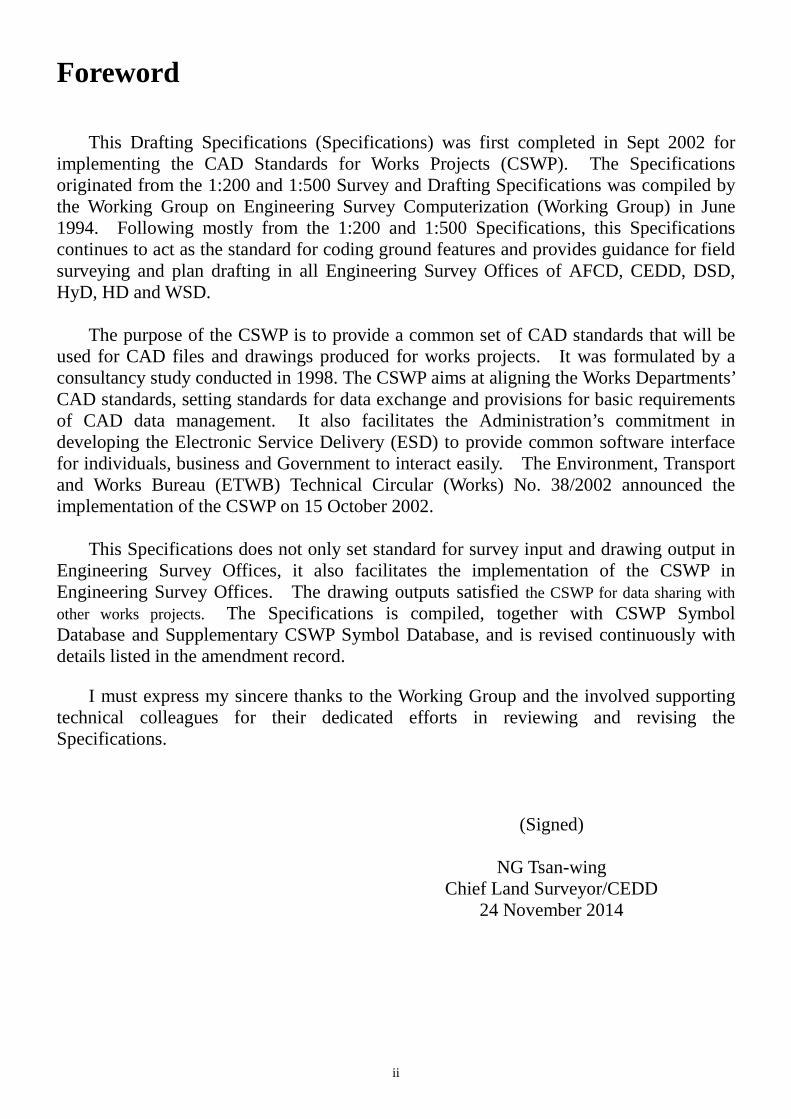
Foreword This Drafting Specifications (Specifications) was first completed in Sept 2002 for implementing the CAD Standards for Works Projects (CSWP). The Specifications originated from the 1:200 and 1:500 Survey and Drafting Specifications was compiled by the Working Group on Engineering Survey Computerization (Working Group) in June 1994. Following mostly from the 1:200 and 1:500 Specifications, this Specifications continues to act as the standard for coding ground features and provides guidance for field surveying and plan drafting in all Engineering Survey Offices of AFCD, CEDD, DSD, HyD, HD and WSD.
The purpose of the CSWP is to provide a common set of CAD standards that will be used for CAD files and drawings produced for works projects. It was formulated by a consultancy study conducted in 1998. The CSWP aims at aligning the Works Departments’ CAD standards, setting standards for data exchange and provisions for basic requirements of CAD data management. It also facilitates the Administration’s commitment in developing the Electronic Service Delivery (ESD) to provide common software interface for individuals, business and Government to interact easily. The Environment, Transport and Works Bureau (ETWB) Technical Circular (Works) No. 38/2002 announced the implementation of the CSWP on 15 October 2002.
This Specifications does not only set standard for survey input and drawing output in Engineering Survey Offices, it also facilitates the implementation of the CSWP in Engineering Survey Offices. The drawing outputs satisfied the CSWP for data sharing with other works projects. The Specifications is compiled, together with CSWP Symbol Database and Supplementary CSWP Symbol Database, and is revised continuously with details listed in the amendment record.
I must express my sincere thanks to the Working Group and the involved supporting
technical colleagues for their dedicated efforts in reviewing and revising the Specifications.
(Signed)
NG Tsan-wing Chief Land Surveyor/CEDD
24 November 2014
iii
Contents
Amendment Record i Foreword ii Contents iii I Introduction 1
II Symbol & Line-style Listing 3
III Symbol & Line-style Details 10
IV CSWP Survey Symbol & Line-style Database 40
V Non-CSWP/Supplementary Survey Symbol & Line-style Database 47
Appendices Appendix A - MicroStation general drawing file settings
61 Appendix B - AutoCAD general drawing file settings 62
Appendix C - Request to Engineering Survey
Computerization Working Group (ESOF-01/Rev2/Aug 2012)
63
P. 1
Part I: Introduction 1.1 What is CSWP
The CAD Standards for Works Projects (CSWP) was formulated by a consultancy study conducted in 1998. CSWP aims at aligning the Works Departments’ CAD standards, setting standards for data exchange and provisions for basic requirements of CAD data management. It also facilitates the Administration’s commitment in developing the Electronic Service Delivery (ESD) for common software interface through which individuals, business and Government can interact easily. Environment, Transport and Works Bureau (ETWB) Technical Circular (Works) No. 38/2002 announced the implementation of CSWP on 15 October 2002. The latest development and information of CSWP can be viewed from CSWP web page (URL: www.devb.gov.hk/en/construction_sector_matters/electronic_services/cad_standard).
1.2 Changes from the 1:200 and 1:500 Survey and Drafting Specification
Basically, this Specifications follows the 1:200 and 1:500 Survey and Drafting Specifications with the objectives of setting standard for survey input and drawing output for Engineering Survey Offices and complying with CSWP. Changes are recorded here for easy reference.
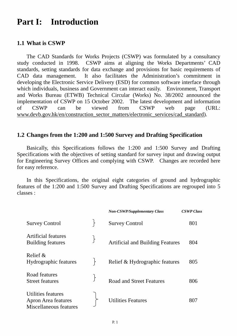
In this Specifications, the original eight categories of ground and hydrographic features of the 1:200 and 1:500 Survey and Drafting Specifications are regrouped into 5 classes :
Non-CSWP/Supplementary Class CSWP Class Survey Control Survey Control 801 Artificial features
Building features Artificial and Building Features 804 Relief &
Hydrographic features Relief & Hydrographic features 805
Road features Street features Road and Street Features 806 Utilities features Apron Area features Utilities Features 807 Miscellaneous features
P. 2
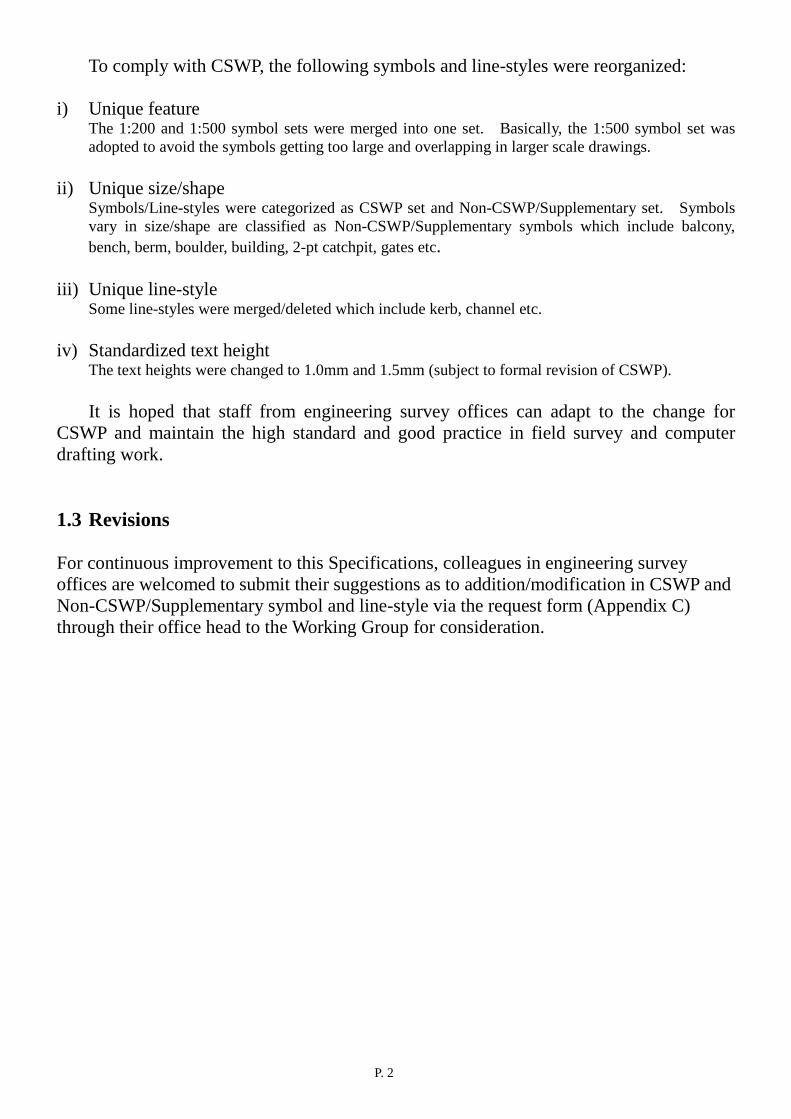
To comply with CSWP, the following symbols and line-styles were reorganized:
i) Unique feature The 1:200 and 1:500 symbol sets were merged into one set. Basically, the 1:500 symbol set was adopted to avoid the symbols getting too large and overlapping in larger scale drawings.
ii) Unique size/shape Symbols/Line-styles were categorized as CSWP set and Non-CSWP/Supplementary set. Symbols vary in size/shape are classified as Non-CSWP/Supplementary symbols which include balcony, bench, berm, boulder, building, 2-pt catchpit, gates etc.
iii) Unique line-style Some line-styles were merged/deleted which include kerb, channel etc.
iv) Standardized text height
The text heights were changed to 1.0mm and 1.5mm (subject to formal revision of CSWP). It is hoped that staff from engineering survey offices can adapt to the change for
CSWP and maintain the high standard and good practice in field survey and computer drafting work. 1.3 Revisions For continuous improvement to this Specifications, colleagues in engineering survey offices are welcomed to submit their suggestions as to addition/modification in CSWP and Non-CSWP/Supplementary symbol and line-style via the request form (Appendix C) through their office head to the Working Group for consideration.
Part II : Symbol & Line-style Listing
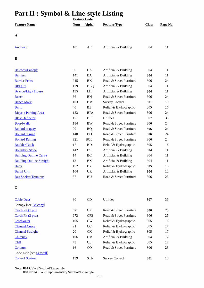
Note: 804 CSWP Symbol/Line-style 804 Non-CSWP/Supplementary Symbol/Line-style P. 3
Feature Code Feature Name Num Alpha Feature Type Class Page No.
A
Archway 101 AR Artificial & Building 804 11
B
Balcony/Canopy 56 CA Artificial & Building 804 11 Barriers 141 BA Artificial & Building 804 11 Barrier Fence 915 BK Road & Street Furniture 806 24 BBQ Pit 179 BBQ Artificial & Building 804 11 Beacon/Light House 135 LH Artificial & Building 804 11 Bench 86 BN Road & Street Furniture 806 24 Bench Mark 103 BM Survey Control 801 10 Berm 40 BE Relief & Hydrographic 805 16 Bicycle Parking Area 183 BPA Road & Street Furniture 806 24 Blast Deflector 151 BF Utilities 807 36 Boardwalk 184 BW Road & Street Furniture 806 24 Bollard at quay 90 BQ Road & Street Furniture 806 24 Bollard at road 140 BO Road & Street Furniture 806 24 Bollard Railing 921 BOL Road & Street Furniture 806 24 Boulder/Rock 17 BD Relief & Hydrographic 805 16 Boundary Stone 142 BS Artificial & Building 804 11 Building Outline Curve 14 BC Artificial & Building 804 11 Building Outline Straight 13 BX Artificial & Building 804 11 Buoy 152 BY Relief & Hydrographic 805 16 Burial Urn 104 UR Artificial & Building 804 12 Bus Shelter/Terminus 87 BU Road & Street Furniture 806 25
C
Cable Duct 80 CD Utilities 807 36 Canopy [see Balcony] Catch Pit (1 pt.) 671 CP1 Road & Street Furniture 806 25 Catch Pit (2 pts.) 672 CP2 Road & Street Furniture 806 25 Catchwater 105 CW Relief & Hydrographic 805 16 Channel Curve 21 CC Relief & Hydrographic 805 17 Channel Straight 20 CX Relief & Hydrographic 805 17 Chimney 106 CM Artificial & Building 804 12 Cliff 43 CL Relief & Hydrographic 805 17 Column 16 CO Road & Street Furniture 806 25 Cope Line [see Seawall] Control Station 139 STN Survey Control 801 10

Part II : Symbol & Line-style Listing
Note: 804 CSWP Symbol/Line-style 804 Non-CSWP/Supplementary Symbol/Line-style P. 4
Feature Code Feature Name Num Alpha Feature Type Class Page No. Covered Walkway 107 CY Road & Street Furniture 806 25 Crash cushion 918 CR Road & Street Furniture 806 25 Cultivation bund/Limit 39 CU Artificial & Building 804 12 Culvert 66 CV Relief & Hydrographic 805 18
D
Dam/Weir 173 DM Relief & Hydrographic 805 18 Distance Post 185 DIS Road & Street Furniture 806 25 Dolphin 108 DO Artificial & Building 804 12 Drain Curve 68 DC Relief & Hydrographic 805 18 Drain Straight 65 DX Relief & Hydrographic 805 18 Draw Pit 154 DP Utilities 807 36 Drop Kerb 919 DK Road & Street Furniture 806 25
E
Electric Pit 155 EI Utilities 807 36 Electric Pole 75 EP Road & Street Furniture 806 26 Electric Sub-station 143 ES Road & Street Furniture 806 26 Electric Transformer 26 ET Road & Street Furniture 806 26 Emergency Gate 907 EG Road & Street Furniture 806 26 Emergency Helpline 188 EH Utilities 807 36 E&M Pit 908 EM Road & Street Furniture 806 26
F
Fanned Outlet 109 FO Relief & Hydrographic 805 19 Fence Curve 31 FC Artificial & Building 804 12 Fence Straight 30 FX Artificial & Building 804 12 Fire Hydrant 27 FH Road & Street Furniture 806 26 Fire Hydrant Pit 172 HI Utilities 807 36 Floodlight Mast 157 FL Utilities 807 36 Flower Bed 88 FB Artificial & Building 804 12 Footpath (Unpaved) 25 FP Road & Street Furniture 806 27 Foot/Rail Bridge 15 BR Road & Street Furniture 806 27 Fountain 144 FN Artificial & Building 804 12 Free Standing Wall Curve 51 WC Artificial & Building 804 13 Free Standing Wall Straight 50 WX Artificial & Building 804 13 Fuel Hydrant Pit 158 FU Utilities 807 36 Fuel Tank [see oil tank] Fuel Valve Pit 156 FV Utilities 807 37
Part II : Symbol & Line-style Listing
Note: 804 CSWP Symbol/Line-style 804 Non-CSWP/Supplementary Symbol/Line-style P. 5
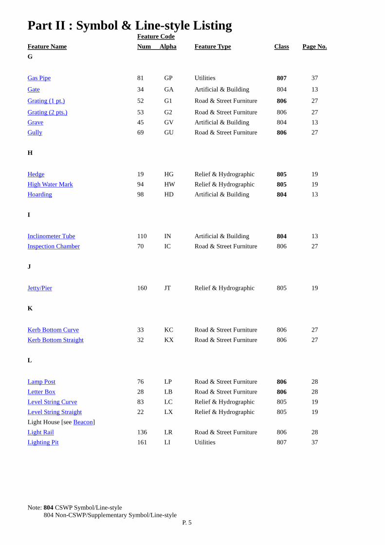
Feature Code Feature Name Num Alpha Feature Type Class Page No. G
Gas Pipe 81 GP Utilities 807 37
Gate 34 GA Artificial & Building 804 13
Grating (1 pt.) 52 G1 Road & Street Furniture 806 27
Grating (2 pts.) 53 G2 Road & Street Furniture 806 27 Grave 45 GV Artificial & Building 804 13 Gully 69 GU Road & Street Furniture 806 27
H
Hedge 19 HG Relief & Hydrographic 805 19 High Water Mark 94 HW Relief & Hydrographic 805 19 Hoarding 98 HD Artificial & Building 804 13
I
Inclinometer Tube 110 IN Artificial & Building 804 13 Inspection Chamber 70 IC Road & Street Furniture 806 27
J
Jetty/Pier 160 JT Relief & Hydrographic 805 19
K
Kerb Bottom Curve 33 KC Road & Street Furniture 806 27 Kerb Bottom Straight 32 KX Road & Street Furniture 806 27
L
Lamp Post 76 LP Road & Street Furniture 806 28 Letter Box 28 LB Road & Street Furniture 806 28 Level String Curve 83 LC Relief & Hydrographic 805 19 Level String Straight 22 LX Relief & Hydrographic 805 19 Light House [see Beacon] Light Rail 136 LR Road & Street Furniture 806 28 Lighting Pit 161 LI Utilities 807 37

Part II : Symbol & Line-style Listing
Note: 804 CSWP Symbol/Line-style 804 Non-CSWP/Supplementary Symbol/Line-style P. 6
Feature Code Feature Name Num Alpha Feature Type Class Page No. M Manhole 60 MH Road & Street Furniture 806 28 Manhole (2 pts.) 602 MH2 Road & Street Furniture 806 28 Manhole Foul Water/Sewer 62 MF Road & Street Furniture 806 28 Manhole Foul Water/Sewer (2 pts.) 622 MF2 Road & Street Furniture 806 28 Manhole Storm Water 61 MS Road & Street Furniture 806 28 Manhole Structure 904 MHS Road & Street Furniture 806 29 Manhole Telephone 63 MT Road & Street Furniture 806 29 Manhole Telephone (2 pts.) 632 MT2 Road & Street Furniture 806 29 Manhole Waterworks 64 MW Road & Street Furniture 806 29 Manhole Waterworks (2 pts.) 642 MW2 Road & Street Furniture 806 29 Marsh/Swamp 113 MA Relief & Hydrographic 805 20 Marshalling Platform 163 MP Utilities 807 37 Mass Transit Railway 114 MTR Road & Street Furniture 806 29 Milestone 149 ME Road & Street Furniture 806 29 Moat [see Pond] Monument/Sculpture/Statue 115 MO Artificial & Building 804 13
N
Noise Barrier Curve 203 NC Road & Street Furniture 806 29 Noise Barrier Straight 204 NX Road & Street Furniture 806 30 Non-carriageway Pavement Centerline 920 NPC Road & Street Furniture 806 30 Nose Tethering Slab 165 NT Utilities 807 37 Nullah 74 NU Relief & Hydrographic 805 20
O
Oil Tank/Water Tank/Fuel Tank 73 TA Artificial & Building 804 14
P
Parking Meter 186 PM Road & Street Furniture 806 30 Pavement/Paved Footpath 24 PA Road & Street Furniture 806 30 Pavement Polygon 906 PX Road & Street Furniture 806 30 Pavilion 116 PV Artificial & Building 804 14 Peak Tramway 117 PT Road & Street Furniture 806 30 Pedestrian Crossing 145 PC Road & Street Furniture 806 30 Pedestrian Subway 36 SU Road & Street Furniture 806 31 Picnic Table & Bench 180 PTB Artificial & Building 804 14 Pier [see Jetty] Piezometer Tube 118 PZ Artificial & Building 804 14 Pillar Box 166 PB Utilities 807 37
Part II : Symbol & Line-style Listing
Note: 804 CSWP Symbol/Line-style 804 Non-CSWP/Supplementary Symbol/Line-style P. 7
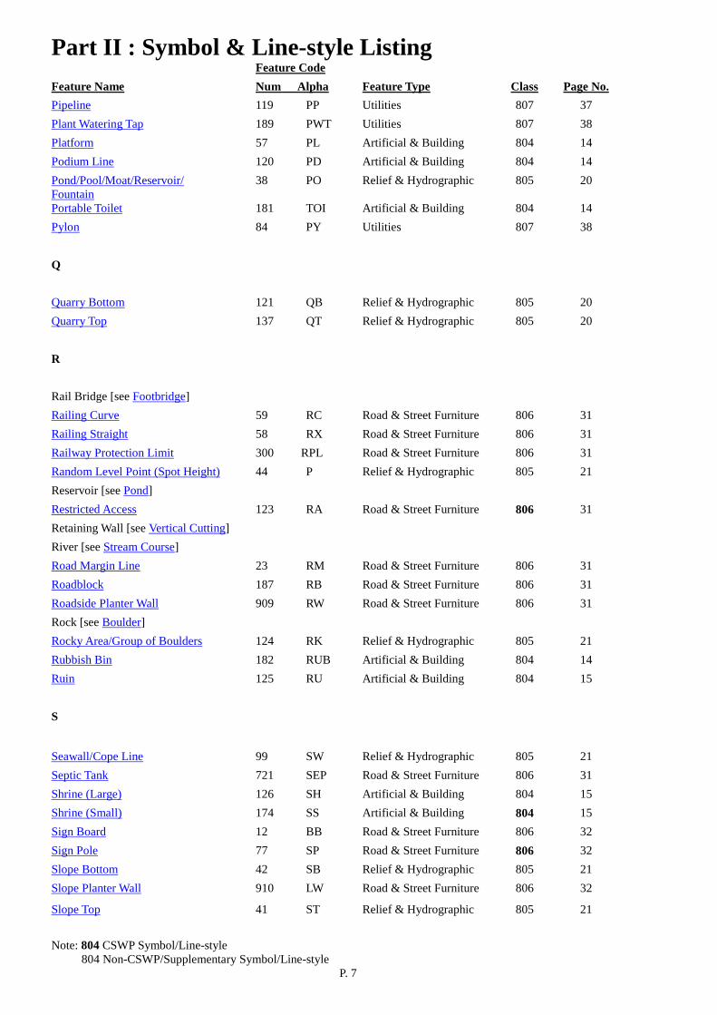
Feature Code Feature Name Num Alpha Feature Type Class Page No. Pipeline 119 PP Utilities 807 37 Plant Watering Tap 189 PWT Utilities 807 38 Platform 57 PL Artificial & Building 804 14 Podium Line 120 PD Artificial & Building 804 14 Pond/Pool/Moat/Reservoir/ Fountain
38 PO Relief & Hydrographic 805 20
Portable Toilet 181 TOI Artificial & Building 804 14 Pylon 84 PY Utilities 807 38 Q
Quarry Bottom 121 QB Relief & Hydrographic 805 20 Quarry Top 137 QT Relief & Hydrographic 805 20 R
Rail Bridge [see Footbridge] Railing Curve 59 RC Road & Street Furniture 806 31 Railing Straight 58 RX Road & Street Furniture 806 31 Railway Protection Limit 300 RPL Road & Street Furniture 806 31 Random Level Point (Spot Height) 44 P Relief & Hydrographic 805 21 Reservoir [see Pond] Restricted Access 123 RA Road & Street Furniture 806 31 Retaining Wall [see Vertical Cutting] River [see Stream Course] Road Margin Line 23 RM Road & Street Furniture 806 31 Roadblock 187 RB Road & Street Furniture 806 31 Roadside Planter Wall 909 RW Road & Street Furniture 806 31 Rock [see Boulder] Rocky Area/Group of Boulders 124 RK Relief & Hydrographic 805 21 Rubbish Bin 182 RUB Artificial & Building 804 14 Ruin 125 RU Artificial & Building 804 15
S
Seawall/Cope Line 99 SW Relief & Hydrographic 805 21 Septic Tank 721 SEP Road & Street Furniture 806 31 Shrine (Large) 126 SH Artificial & Building 804 15 Shrine (Small) 174 SS Artificial & Building 804 15 Sign Board 12 BB Road & Street Furniture 806 32 Sign Pole 77 SP Road & Street Furniture 806 32 Slope Bottom 42 SB Relief & Hydrographic 805 21 Slope Planter Wall 910 LW Road & Street Furniture 806 32
Slope Top 41 ST Relief & Hydrographic 805 21

Part II : Symbol & Line-style Listing
Note: 804 CSWP Symbol/Line-style 804 Non-CSWP/Supplementary Symbol/Line-style P. 8
Feature Code Feature Name Num Alpha Feature Type Class Page No. Slot Drain 167 SD Utilities 807 38 Soil Nail 127 SN Artificial & Building 804 15 Special Paving Panel 911 SPP Road & Street Furniture 806 32 Stair/Step Edge 35 SI Road & Street Furniture 806 32 Stepped Channel Curve 128 SC Relief & Hydrographic 805 22 Stepped Channel Straight 129 SX Relief & Hydrographic 805 22 Strategic Route Chainage Marker 916 ECM Road & Street Furniture 806 32 Street Name Plate 913 SNP Road & Street Furniture 806 32 Stream Course/River 37 SR Relief & Hydrographic 805 23 Swamp [see Marsh] T
Tactile Paving 912 TV Road & Street Furniture 806 32
Tank [see Oil Tank] Taxiway Light 162 LT Utilities 807 38 Taxiway Marking 159 AM Utilities 807 38 Telephone Chamber 169 TC Utilities 807 38 Telephone Kiosk 89 TK Road & Street Furniture 806 32 Telephone Pole 79 TP Road & Street Furniture 806 33 Temporary Structure 97 TS Artificial & Building 804 15 Tide Gauge 130 TG Relief & Hydrographic 805 23 Track 131 TR Road & Street Furniture 806 33 Traffic Island 146 TI Road & Street Furniture 806 33 Traffic Light 78 TL Road & Street Furniture 806 33 Traffic Light Control Box 147 TB Road & Street Furniture 806 33 Tramway 138 TW Road & Street Furniture 806 33 Transformer Pit 170 TT Utilities 807 38 Tree 18 TE Relief & Hydrographic 805 23 Trigonometrical Station 23 TRI Survey Control 801 10 Tunnel 133 TU Road & Street Furniture 806 33 Tunnel Chainage Marker 917 TCM Road & Street Furniture 806 34
U
Unclassified Dot/Point Features 29 XP Utilities 807 38 Unclassified Firm Line Structure Curve 47 XC Utilities 807 39 Unclassified Firm Line Structure Straight 46 XX Utilities 807 39 Unclassified Long Dash Line 48 XL Utilities 807 39 Unclassified Short Dash Line 49 XS Utilities 807 39 Utility Box 261 UB Road & Street Furniture 806 34

Part II : Symbol & Line-style Listing
Note: 804 CSWP Symbol/Line-style 804 Non-CSWP/Supplementary Symbol/Line-style P. 9
Feature Code Feature Name Num Alpha Feature Type Class Page No. V
Valve 71 VV Road & Street Furniture 806 34 Valve Fire 91 VF Road & Street Furniture 806 34 Valve Gas 92 VG Road & Street Furniture 806 34
Valve Waterworks 93 VW Road & Street Furniture 806 34 Vertical Cutting/Masonry/ Retaining Wall
54 WR Relief & Hydrographic 805 23
Visitor Sign Post 914 VS Road & Street Furniture 806 35 W
Water Main 82 WM Road & Street Furniture 806 35 Water Point 171 WP Utilities 807 39 Water Tank [see Oil Tank] Weir [see Dam] Well 72 WL Artificial & Building 804 15 Works in Progress Limit 134 WIP Artificial & Building 804 15
Part III: Symbol & Line-style Details
P. 10
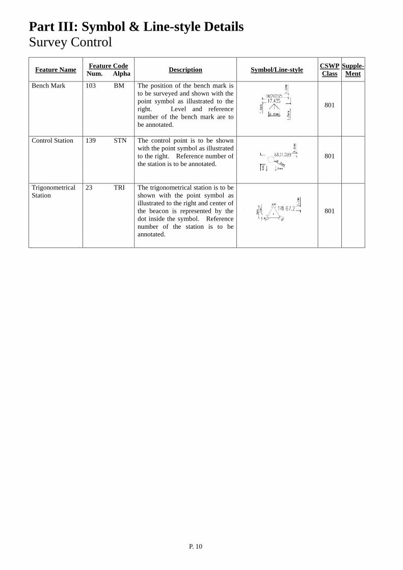
Survey Control
Feature Name Feature Code
Num. Alpha
Description
Symbol/Line-style CSWP
Class Supple- Ment
Bench Mark 103 BM The position of the bench mark is to be surveyed and shown with the point symbol as illustrated to the right. Level and reference number of the bench mark are to be annotated.
801
Control Station 139 STN The control point is to be shown
with the point symbol as illustrated to the right. Reference number of the station is to be annotated.
801
Trigonometrical Station
23 TRI The trigonometrical station is to be shown with the point symbol as illustrated to the right and center of the beacon is represented by the dot inside the symbol. Reference number of the station is to be annotated.
801
Part III: Symbol & Line-style Details
P. 11
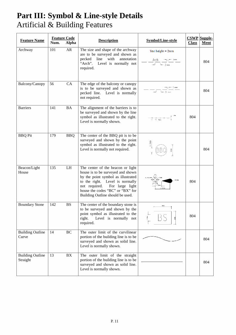
Artificial & Building Features
Feature Name
Feature Code Num. Alpha
Description
Symbol/Line-style CSWP
Class Supple-
Ment Archway 101 AR The size and shape of the archway
are to be surveyed and shown as pecked line with annotation “Arch”. Level is normally not required.
804
Balcony/Canopy 56 CA The edge of the balcony or canopy
is to be surveyed and shown as pecked line. Level is normally not required.
804
Barriers 141 BA The alignment of the barriers is to
be surveyed and shown by the line symbol as illustrated to the right. Level is normally shown.
804
BBQ Pit 179 BBQ The center of the BBQ pit is to be
surveyed and shown by the point symbol as illustrated to the right. Level is normally not required.
804
Beacon/Light House
135 LH The center of the beacon or light house is to be surveyed and shown by the point symbol as illustrated to the right. Level is normally not required. For large light house the codes “BC” or “BX” for Building Outline should be used.
804
Boundary Stone 142 BS The center of the boundary stone is
to be surveyed and shown by the point symbol as illustrated to the right. Level is normally not required.
804
Building Outline Curve
14 BC The outer limit of the curvilinear portion of the building line is to be surveyed and shown as solid line. Level is normally shown.
804
Building Outline Straight
13 BX The outer limit of the straight portion of the building line is to be surveyed and shown as solid line. Level is normally shown.
804
Part III: Symbol & Line-style Details
P. 12
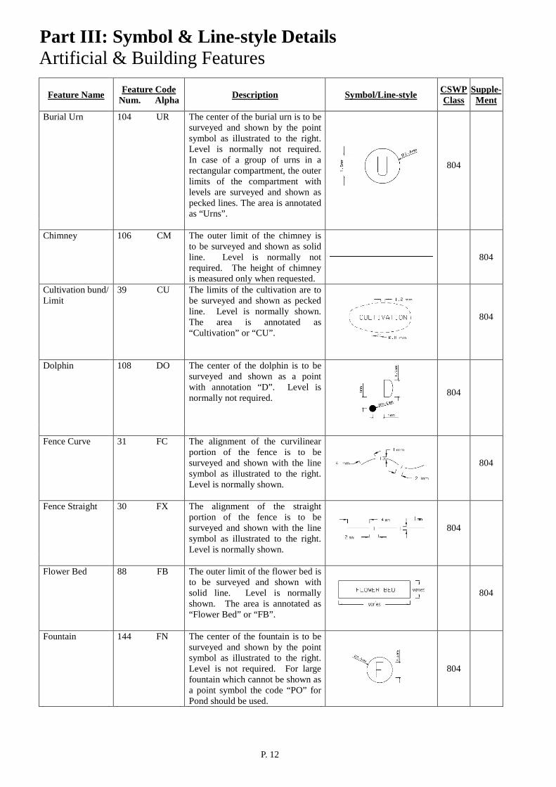
Artificial & Building Features
Feature Name
Feature Code Num. Alpha
Description
Symbol/Line-style CSWP
Class Supple-
Ment Burial Urn 104 UR The center of the burial urn is to be
surveyed and shown by the point symbol as illustrated to the right. Level is normally not required. In case of a group of urns in a rectangular compartment, the outer limits of the compartment with levels are surveyed and shown as pecked lines. The area is annotated as “Urns”.
804
Chimney 106 CM The outer limit of the chimney is
to be surveyed and shown as solid line. Level is normally not required. The height of chimney is measured only when requested.
804
Cultivation bund/ Limit
39 CU The limits of the cultivation are to be surveyed and shown as pecked line. Level is normally shown. The area is annotated as “Cultivation” or “CU”.
804
Dolphin 108 DO The center of the dolphin is to be
surveyed and shown as a point with annotation “D”. Level is normally not required.
804
Fence Curve 31 FC The alignment of the curvilinear
portion of the fence is to be surveyed and shown with the line symbol as illustrated to the right. Level is normally shown.
804
Fence Straight 30 FX The alignment of the straight
portion of the fence is to be surveyed and shown with the line symbol as illustrated to the right. Level is normally shown.
804
Flower Bed 88 FB The outer limit of the flower bed is
to be surveyed and shown with solid line. Level is normally shown. The area is annotated as “Flower Bed” or “FB”.
804
Fountain 144 FN The center of the fountain is to be
surveyed and shown by the point symbol as illustrated to the right. Level is not required. For large fountain which cannot be shown as a point symbol the code “PO” for Pond should be used.
804

Part III: Symbol & Line-style Details
P. 13
Artificial & Building Features
Feature Name
Feature Code Num. Alpha
Description
Symbol/Line-style CSWP
Class Supple-
Ment Free Standing Wall Curve
51 WC The alignment of the curvilinear portion of the free standing wall is to be surveyed and shown by the line symbol as illustrated to the right. Level is normally shown. Height and width of the wall are measured when necessary.
804
Free Standing Wall Straight
50 WX The alignment of the straight portion of the free standing wall is to be surveyed and shown by the line symbol as illustrated to the right. Level is normally shown. Height and width of the wall are measured when necessary.
804
Gate 34 GA The two end points of the gate are
to be surveyed and shown by the symbol as illustrated to the right. Level is normally shown.
804
Grave 709 GV2 45 GV
For small grave, two opposite end points of the grave are to be surveyed and shown by symbol as illustrated to the right with the orientation defined by the two surveyed points. It is annotated as ‘G’. Level is normally not required. For large grave, the outer limit of the grave is to be surveyed and shown as solid line. Level is normally shown.
small grave text ht varies
large grave
804
Hoarding 98 HD The alignment of hoarding is to be
surveyed and shown as pecked line with the annotation “HD” at regular intervals. Level is normally shown.
804
Inclinometer Tube
110 IN The center and cover level of the inclinometer tube are to be surveyed and shown by a circle annotated with “IN”. The reference number of the inclinometer is to be annotated.
804
Monument/ Sculpture/Statue
115 MO The center of the monument, sculpture or statue is to be surveyed and shown by the point symbol as illustrated to the right. Level is normally not required.
804

Part III: Symbol & Line-style Details
P. 14
Artificial & Building Features
Feature Name
Feature Code Num. Alpha
Description
Symbol/Line-style CSWP
Class Supple-
Ment Oil Tank/Water Tank/Fuel Tank
73 TA The outer limit of the tank are to be surveyed and shown as solid line. Level is normally shown if the tank is on ground. The area is to be annotated as “Oil Tank”, “Water Tank”, “Fuel Tank” or “TA” accordingly.
804
Pavilion 116 PV The outer limit of the pavilion is to
be surveyed and shown as solid line. Level is normally shown.
804
Picnic Table and Bench
180 PTB The center of the picnic table and bench is to be surveyed and shown by the symbol as illustrated to the right. Level is normally not required.
804
Piezometer Tube 118 PZ The center and cover level of the piezometer tube are to be surveyed and shown by a square annotated with “PZ”. The reference number of the piezometer is annotated when required.
804
Platform 57 PL The outer limit of the platform is
to be surveyed and shown as solid line. Level is normally shown.
804
Podium Line 120 PD The outer limit of the podium is to
be surveyed and shown as solid line. Level is normally shown.
804
Portable Toilet 181 TOI The mid points of the shorter sides
of the portable toilet are to be surveyed and shown by the symbol as illustrated to the right with orientation defined by the line joining the two surveyed points and annotated as “TOI” with fixed height characters. Level is normally not required.
804
Rubbish Bin 182 RUB The center of the ground fixed rubbish bin is to be surveyed. It is shown as a point with annotation “RUB”. Level is normally not required.
804
Part III: Symbol & Line-style Details
P. 15
Artificial & Building Features
Feature Name
Feature Code Num. Alpha
Description
Symbol/Line-style CSWP
Class Supple-
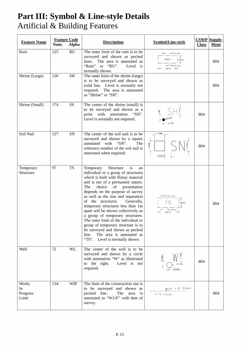
Ment Ruin 125 RU The outer limit of the ruin is to be
surveyed and shown as pecked lines. The area is annotated as “Ruin” or “RU”. Level is normally shown.
804
Shrine (Large) 126 SH The outer limit of the shrine (large) is to be surveyed and shown as solid line. Level is normally not required. The area is annotated as “Shrine” or “SH”.
804
Shrine (Small) 174 SS The center of the shrine (small) is
to be surveyed and shown as a point with annotation “SH”. Level is normally not required.
804
Soil Nail 127 SN The center of the soil nail is to be
surveyed and shown by a square annotated with “SN”. The reference number of the soil nail is annotated when required.
804
Temporary Structure
97 TS Temporary Structure is an individual or a group of structures which is built with flimsy material and is not of a permanent nature. The choice of presentation depends on the purpose of survey as well as the size and separation of the structures. Generally, temporary structures less than 1m apart will be shown collectively as a group of temporary structures. The outer limit of the individual or group of temporary structure is to be surveyed and shown as pecked line. The area is annotated as “TS”. Level is normally shown.
804
Well 72 WL The center of the well is to be
surveyed and shown by a circle with annotation “W” as illustrated to the right. Level is not required.
804
Works In Progress Limit
134 WIP The limit of the construction site is to be surveyed and shown as pecked line. The area is annotated as “W.I.P.” with date of survey.
804

Part III: Symbol & Line-style Details
P. 16
Relief & Hydrographic Features
Feature Name Feature Code
Num. Alpha
Description
Symbol/Line-style CSWP
Class Supple-
ment Berm 40 BE Berm refers to the horizontal
platform inside an artificial slope, usually bounded by the edge of slope and surface channels. The edge of slope marking the berm is to be surveyed and shown as pecked line. Level is normally shown.
805
Boulder/Rock 17 BD Only those large boulders, exposed
rock or rock outcrops required for engineering design are to be surveyed and shown as pecked lines. Level is normally shown. The level of the highest point of the boulder is to be surveyed and shown if possible.
805
Buoy 152 BY The position of the buoy is to be
surveyed and shown by the point symbol as illustrated to the right. Level is not required.
805
Catchwater 105 CW The upper/outer and the
lower/inner limits of the catchwater are to be surveyed and shown as solid lines. Level is normally shown. The invert level and details like sandtrap, overflow etc. are surveyed when necessary.
805

Part III: Symbol & Line-style Details
P. 17
Relief & Hydrographic Features
Feature Name Feature Code
Num. Alpha
Description
Symbol/Line-style CSWP
Class Supple-
ment Channel Curve 21 CC (For 1:200)
The alignment, size, shape and when necessary the invert level of the curvilinear portion of the surface channel are to be surveyed and shown by single solid line or double solid lines representing a channel width apart. The direction of flow is to be indicated by direction arrows at suitable intervals. The width with annotation “UC” is to be annotated when necessary. (For 1:500) The centerline and the invert level of the curvilinear portion of the surface channel are to be surveyed and shown as solid line. The direction of flow is to be indicated by direction arrows at suitable intervals. The diameter and type of channel are to be surveyed and annotated.
805
Channel Straight 20 CX (For 1:200) The alignment, size, shape and when necessary the invert level of the straight portion of the surface channel are to be surveyed and shown by single solid line or double solid lines representing a channel width apart. The direction of flow is to be indicated by direction arrows at suitable intervals. The width with annotation “UC” is to be annotated when necessary. (For 1:500) The centerline and the invert level of the straight portion of the surface channel are to be surveyed and shown as solid line. The direction of flow is to be indicated by direction arrows at suitable intervals. The diameter and type of channel are to be surveyed and annotated.
805
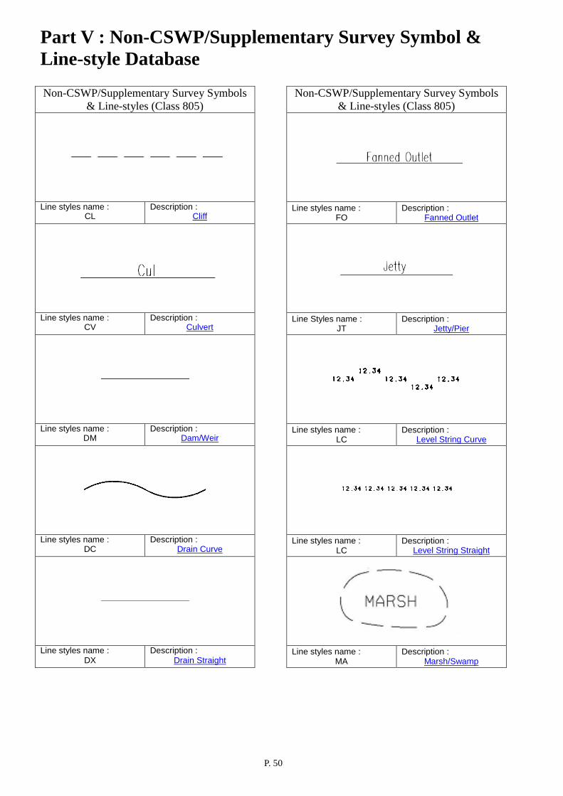
Cliff 43 CL The top and bottom edges of the cliff are to be surveyed and shown as pecked line. Level is normally shown. The details and levels of the overhanging and caved-in structure are surveyed when necessary.
805

Part III: Symbol & Line-style Details
P. 18
Relief & Hydrographic Features
Feature Name Feature Code
Num. Alpha
Description
Symbol/Line-style CSWP
Class Supple-
ment Culvert 66 CV The size and shape of the culvert is
to be surveyed and shown as solid line with annotation “Cul”. Level is normally shown. Invert level of the culvert is to be surveyed when necessary.
805
Dam/Weir 173 DM The outer limits of the dam or weir
are to be surveyed and shown as solid lines. The external dam wall may be shown with appropriate pattern symbol. Level is normally shown.
805
Drain Curve 68 DC (For 1:200)
The alignment, size, shape and invert level of the curvilinear portion of the drain are to be surveyed and shown as solid line. The direction of flow is to be indicated by direction arrows at suitable intervals. The diameter and type of drain are to be surveyed and annotated. (For 1:500) The alignment and invert level of the curvilinear portion of the drain are to be surveyed and shown as solid line. The direction of flow is to be indicated by direction arrows at suitable intervals. The diameter and type of drain are to be surveyed and annotated.
805
Drain Straight 65 DX (For 1:200)
The alignment, size, shape and invert level of the straight portion of the drain are to be surveyed and shown as solid line. The direction of flow is to be indicated by direction arrows at suitable intervals. The diameter and type of drain are to be surveyed and annotated. (For 1:500) The alignment and invert level of the straight portion of the drain are to be surveyed and shown as solid line. The direction of flow is to be indicated by direction arrows at suitable intervals. The diameter and type of drain are to be surveyed and annotated.
805

Part III: Symbol & Line-style Details
P. 19
Relief & Hydrographic Features
Feature Name Feature Code
Num. Alpha
Description
Symbol/Line-style CSWP
Class Supple-
ment Fanned Outlet 109 FO
The outer limits of the outlet are to
be surveyed and shown as solid line. Level is normally not required. The area is to be annotated as “Fanned Outlet” or “FO”.
805
Hedge 19 HG The centerline of the hedge is to be
surveyed and shown by the line symbol as illustrated to the right. Level is normally not required.
805
High Water Mark 94 HW As decided by the Mapping Policy
Committee on 24.7.1991, the 2.3 metre (above Principal Datum) contour line is to be adopted as the high water mark. It is shown as a pecked line with the annotation “HWM” at regular intervals.
805
Jetty/Pier 160 JT The outer limits of the jetty or pier
are to be surveyed and shown as solid lines. The area should be annotated as “Jetty” or “Pier” accordingly. Level is normally shown.
805
Level String Curve
83 LC Level strings (curvilinear) are invisible 3-dimensional lines in space with height values with respect to Hong Kong Principal Datum. These lines are either surveyed or interpolated from surveyed points.
805
Level String Straight
22 LX Level strings (straight) are invisible 3-dimensional lines in space with height values with respect to Hong Kong Principal Datum. These lines are either surveyed or interpolated from surveyed points.
805

Part III: Symbol & Line-style Details
P. 20
Relief & Hydrographic Features
Feature Name Feature Code
Num. Alpha
Description
Symbol/Line-style CSWP
Class Supple-
ment Marsh/Swamp 113 MA The outer limit of the marsh or
swamp is to be surveyed and shown as pecked line. The area is to be annotated as “Marsh” or “MA”. Level is normally shown.
805
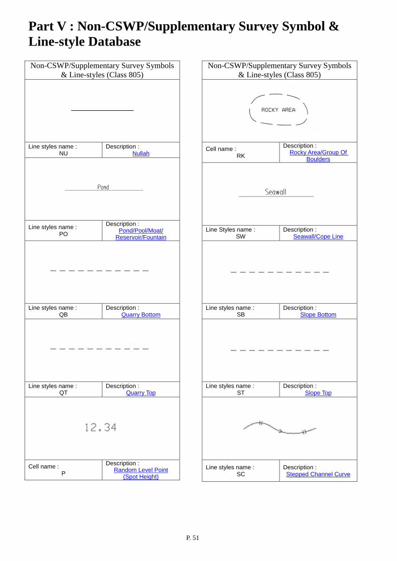
Nullah 74 NU The outer/upper and inner/lower limits of an open nullah are to be surveyed and shown as solid lines. Level is normally shown. Invert level and details inside the nullah are surveyed only when necessary. The direction of flow is indicated by direction arrows. For covered and decked nullah only the outer/upper limits are to be surveyed and shown as pecked lines.
805
Pond/ Pool/ Moat/ Reservoir/ Fountain
38 PO The upper/outer limits of ponds, swimming pools, moats, reservoirs and large fountains etc. are to be surveyed and shown as solid lines. The area is annotated as “Pond”, “Pool”, “Sw P” or “Fountain” accordingly. Level is normally shown. For small fountain the code “FN” for Fountain should be used. For open reservoir, the limit of the reservoir is determined by the water level at full capacity and is shown as solid line. The area is to be annotated as “Reservoir”. For covered reservoir, the limit of the reservoir is shown as pecked line and the area is annotated as “Reservoir Under”.
805
Quarry Bottom 121 QB
The bottom limits of the quarry
platforms are to be surveyed and shown as pecked lines. Level is normally shown.
805
Quarry Top 137 QT The top limits of the quarry
platforms are to be surveyed and shown as pecked lines. Level is normally shown.
805
Part III: Symbol & Line-style Details
P. 21
Relief & Hydrographic Features
Feature Name Feature Code
Num. Alpha
Description
Symbol/Line-style CSWP
Class Supple-
ment Random Level Point (Spot Height)
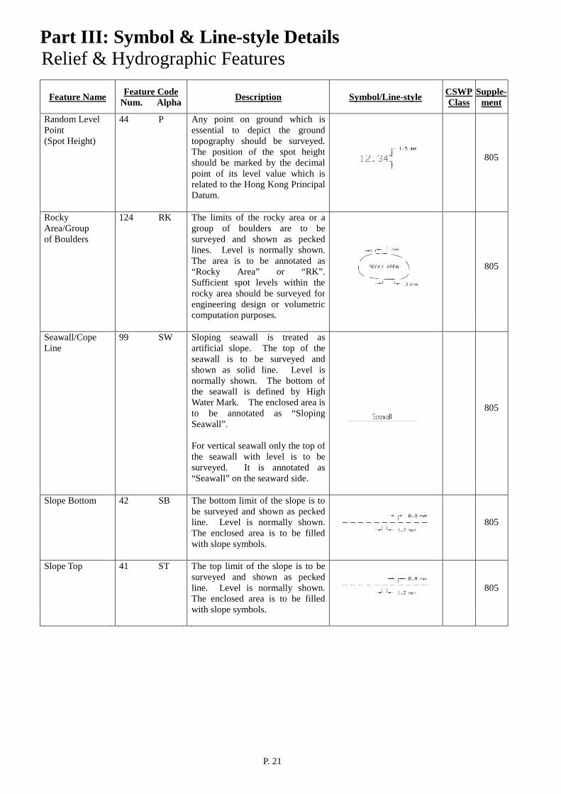
44 P Any point on ground which is essential to depict the ground topography should be surveyed. The position of the spot height should be marked by the decimal point of its level value which is related to the Hong Kong Principal Datum.
805
Rocky Area/Group of Boulders
124 RK The limits of the rocky area or a group of boulders are to be surveyed and shown as pecked lines. Level is normally shown. The area is to be annotated as “Rocky Area” or “RK”. Sufficient spot levels within the rocky area should be surveyed for engineering design or volumetric computation purposes.
805
Seawall/Cope Line
99 SW Sloping seawall is treated as artificial slope. The top of the seawall is to be surveyed and shown as solid line. Level is normally shown. The bottom of the seawall is defined by High Water Mark. The enclosed area is to be annotated as “Sloping Seawall”. For vertical seawall only the top of the seawall with level is to be surveyed. It is annotated as “Seawall” on the seaward side.
805
Slope Bottom 42 SB The bottom limit of the slope is to
be surveyed and shown as pecked line. Level is normally shown. The enclosed area is to be filled with slope symbols.
805
Slope Top 41 ST The top limit of the slope is to be
surveyed and shown as pecked line. Level is normally shown. The enclosed area is to be filled with slope symbols.
805
Part III: Symbol & Line-style Details
P. 22
Relief & Hydrographic Features
Feature Name Feature Code
Num. Alpha
Description
Symbol/Line-style CSWP
Class Supple-
ment Stepped Channel Curve
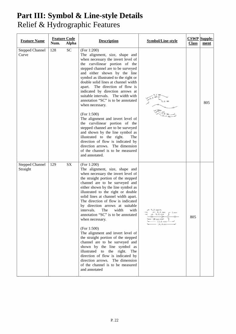
128 SC (For 1:200) The alignment, size, shape and when necessary the invert level of the curvilinear portion of the stepped channel are to be surveyed and either shown by the line symbol as illustrated to the right or double solid lines at channel width apart. The direction of flow is indicated by direction arrows at suitable intervals. The width with annotation “SC” is to be annotated when necessary. (For 1:500) The alignment and invert level of the curvilinear portion of the stepped channel are to be surveyed and shown by the line symbol as illustrated to the right. The direction of flow is indicated by direction arrows. The dimension of the channel is to be measured and annotated.
805
Stepped Channel Straight
129 SX
(For 1:200) The alignment, size, shape and when necessary the invert level of the straight portion of the stepped channel are to be surveyed and either shown by the line symbol as illustrated to the right or double solid lines at channel width apart. The direction of flow is indicated by direction arrows at suitable intervals. The width with annotation “SC” is to be annotated when necessary. (For 1:500) The alignment and invert level of the straight portion of the stepped channel are to be surveyed and shown by the line symbol as illustrated to the right. The direction of flow is indicated by direction arrows. The dimension of the channel is to be measured and annotated
805

Part III: Symbol & Line-style Details
P. 23
Relief & Hydrographic Features
Feature Name Feature Code
Num. Alpha
Description
Symbol/Line-style CSWP
Class Supple-
ment Stream Course/ River
37 SR
For narrow stream course, the alignment of the stream is to be surveyed and shown as solid line. Level is normally shown. The direction of flow is indicated by direction arrows. For wide stream course and river, the limits of the stream or the bank of river are to be surveyed and shown as solid lines.
805
Tide Gauge 130 TG
The position of the tide gauge is to
be surveyed and shown as a point with annotation “TG”. Level is normally not required.
805
Tree 18 TE The position of the tree is to be
surveyed and shown by the point symbol as illustrated to the right. Level, Diameter Breast Height (DBH) of the trunk, height and the spread of foliage are to be measured and annotated when requested.
805
Vertical Cutting/ Masonry/ Retaining Wall
54 WR The alignment of the vertical cutting or retaining wall is to be surveyed and shown by the line symbol as illustrated to the right. For sloping retaining wall both the top and the bottom are to be surveyed. The height and gradient of the wall is to be surveyed when requested.
805

Part III: Symbol & Line-style Details
P. 24
Road & Street Furniture Features
Feature Name
Feature Code Num. Alpha
Description
Symbol/Line-style CSWP
Class Supple-
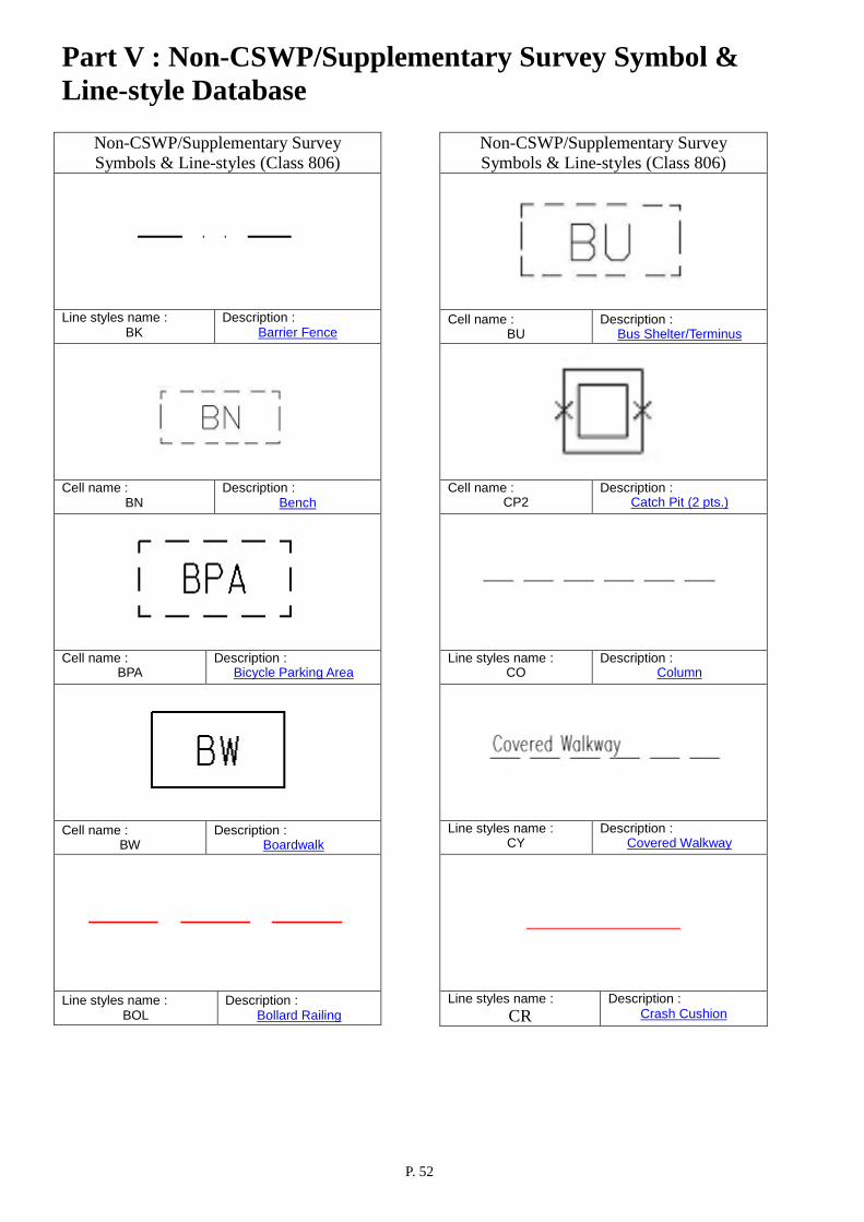
ment Barrier Fence 915 BK The centerline of the barrier fence
is to be surveyed and shown as pecked line.
806
Bench 86 BN The outer limit of the bench is to be surveyed and shown as pecked line. The area is annotated as “BN”. Level is normally not required.
Text height varies
806
Bicycle Parking Area
183 BPA The outer limit of the bicycle parking area is to be surveyed and shown as pecked line. The area is annotated as “BPA”. Level is normally shown.
806
Boardwalk 184 BW The outer limit of the boardwalk is to be surveyed and shown with solid line. The area is annotated as “BW”. Level is normally shown.
806
Bollard at quay 90 BQ The center of the bollard at quay is to be surveyed and shown by a point symbol as illustrated to the right. Level is normally not required.
806
Bollard at road 140 BO The center of the bollard at road is
to be surveyed and shown by a point symbol as illustrated to the right. Level is normally not required.
806
Bollard Railing 921 BOL The line of the bollard railing is to
be surveyed and shown as red dash line.
806

Part III: Symbol & Line-style Details
P. 25
Road & Street Furniture Features
Feature Name
Feature Code Num. Alpha
Description
Symbol/Line-style CSWP
Class Supple-
ment Bus Shelter/ Terminus
87 BU The outer limit of the bus shelter/terminus is to be surveyed and shown as pecked line. The area is annotated as “BU”. Level is normally not required.
806
Catch Pit (1 pt.) 671 CP1 The center of the catch pit is to be surveyed and shown by the symbol as illustrated to the right. Level is normally not required. Invert level, sump level, inlet and outlet levels etc. are to be surveyed when directed.
806
Catch Pit (2 pts.) 672 CP2
The mid-points of the opposite sides of the catch pit are to be surveyed and shown by the symbol as illustrated to the right with orientation defined by the line joining the two surveyed points. Level is normally not required. Invert level, sump level, inlet and outlet levels etc. are to be surveyed when directed.
806
Column 16 CO The perimeter of the column is to be surveyed and shown as pecked line. Level is normally not required.
806
Covered Walkway
107 CY The outer limits of the covered walkway are to be surveyed and shown as pecked lines. It is annotated as “Covered Walkway”. Level is normally shown.
806
Crash Cushion 918 CR The centerline of the crash cushion is to be surveyed along the traffic direction, drawing from the nosing to end of the crash cushion system and shown as red solid line.
806
Distance Post 185 DIS The position of the distance post is to be surveyed and shown by a point symbol as illustrated to the right. Level is normally not required.
806
Drop Kerb 919 DK The line of the drop kerb is to be surveyed and shown as solid line.
806
Part III: Symbol & Line-style Details
P. 26
Road & Street Furniture Features
Feature Name
Feature Code Num. Alpha
Description
Symbol/Line-style CSWP
Class Supple-
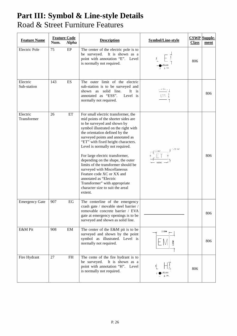
ment Electric Pole 75 EP The center of the electric pole is to
be surveyed. It is shown as a point with annotation “E”. Level is normally not required.
806
Electric Sub-station
143 ES The outer limit of the electric sub-station is to be surveyed and shown as solid line. It is annotated as “ESS”. Level is normally not required.
806
Electric Transformer
26 ET For small electric transformer, the mid points of the shorter sides are to be surveyed and shown by symbol illustrated on the right with the orientation defined by the surveyed points and annotated as “ET” with fixed height characters. Level is normally not required. For large electric transformer, depending on the shape, the outer limits of the transformer should be surveyed with Miscellaneous Feature code XC or XX and annotated as “Electric Transformer” with appropriate character size to suit the areal extent.
806
Emergency Gate 907 EG The centerline of the emergency crash gate / movable steel barrier / removable concrete barrier / EVA gate at emergency openings is to be surveyed and shown as solid line.
806
E&M Pit 908 EM The center of the E&M pit is to be surveyed and shown by the point symbol as illustrated. Level is normally not required.
806
Fire Hydrant 27 FH The cente of the fire hydrant is to be surveyed. It is shown as a point with annotation “H”. Level is normally not required.
806

Part III: Symbol & Line-style Details
P. 27
Road & Street Furniture Features
Feature Name
Feature Code Num. Alpha
Description
Symbol/Line-style CSWP
Class Supple-
ment Footpath (Unpaved)
25 FP The limits of unpaved footpath are to be surveyed and shown as pecked lines. The footpath is annotated as “Footpath” or “FP”. Level is normally shown. For paved footpath the code “PA” for Pavement/Paved Footpath should be used.
806
Foot/Rail Bridge 15 BR The outer limits of the foot/rail bridge are to be surveyed and shown as solid lines. It is annotated as “Footbridge” or “Railbridge” accordingly. Level is normally shown.
806
Grating (1 pt.) 52 G1 The center of the grating is to be
surveyed and shown by the point symbol as illustrated to the right. Level is normally not required.
806
Grating (2 pts.) 53 G2 The mid-points of the opposite
sides of the grating are to be surveyed and shown by the symbol as illustrated to the right with orientation defined by the line joining the two surveyed points. Level is normally not required.
806
Gully 69 GU The center of the gully is to be
surveyed and shown as a circle as illustrated to the right. Level is normally not required.
806
Inspection Chamber
70 IC The outer limit of the inspection chamber is to be surveyed and shown as solid line. It is annotated as “IC”. Level is normally not required.
806
Kerb Bottom Curve
33 KC The alignment and level of the curvilinear portion of kerb bottom are to be surveyed and shown as solid line.
806
Kerb Bottom Straight
32 KX The alignment and level of the straight portion of kerb bottom are to be surveyed and shown as solid line.
806
Part III: Symbol & Line-style Details
P. 28
Road & Street Furniture Features
Feature Name
Feature Code Num. Alpha
Description
Symbol/Line-style CSWP
Class Supple-
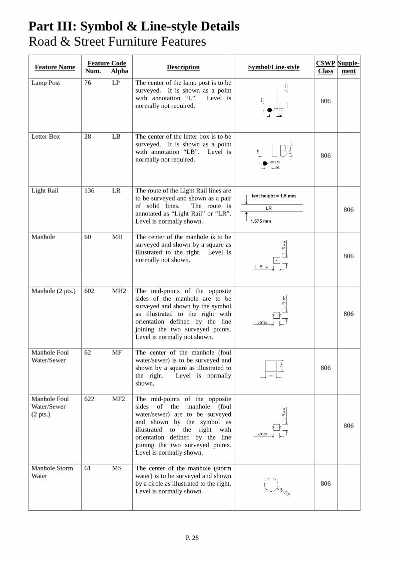
ment Lamp Post 76 LP The center of the lamp post is to be
surveyed. It is shown as a point with annotation “L”. Level is normally not required.
806
Letter Box 28 LB The center of the letter box is to be
surveyed. It is shown as a point with annotation “LB”. Level is normally not required.
806
Light Rail 136 LR The route of the Light Rail lines are
to be surveyed and shown as a pair of solid lines. The route is annotated as “Light Rail” or “LR”. Level is normally shown.
806
Manhole 60 MH The center of the manhole is to be surveyed and shown by a square as illustrated to the right. Level is normally not shown.
806
Manhole (2 pts.) 602 MH2 The mid-points of the opposite
sides of the manhole are to be surveyed and shown by the symbol as illustrated to the right with orientation defined by the line joining the two surveyed points. Level is normally not shown.
806
Manhole Foul Water/Sewer
62 MF The center of the manhole (foul water/sewer) is to be surveyed and shown by a square as illustrated to the right. Level is normally shown.
806
Manhole Foul Water/Sewer (2 pts.)
622 MF2 The mid-points of the opposite sides of the manhole (foul water/sewer) are to be surveyed and shown by the symbol as illustrated to the right with orientation defined by the line joining the two surveyed points. Level is normally shown.
806
Manhole Storm Water
61 MS The center of the manhole (storm water) is to be surveyed and shown by a circle as illustrated to the right. Level is normally shown.
806
Part III: Symbol & Line-style Details
P. 29
Road & Street Furniture Features
Feature Name
Feature Code Num. Alpha
Description
Symbol/Line-style CSWP
Class Supple-
ment Manhole Structure
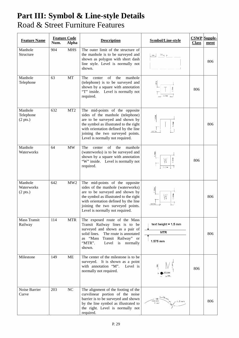
904 MHS The outer limit of the structure of the manhole is to be surveyed and shown as polygon with short dash line style. Level is normally not shown.
806
Manhole Telephone
63 MT The center of the manhole (telephone) is to be surveyed and shown by a square with annotation “T” inside. Level is normally not required.
806
Manhole Telephone (2 pts.)
632 MT2 The mid-points of the opposite sides of the manhole (telephone) are to be surveyed and shown by the symbol as illustrated to the right with orientation defined by the line joining the two surveyed points. Level is normally not required.
806
Manhole Waterworks
64 MW The center of the manhole (waterworks) is to be surveyed and shown by a square with annotation “W” inside. Level is normally not required.
806
Manhole Waterworks (2 pts.)
642 MW2 The mid-points of the opposite sides of the manhole (waterworks) are to be surveyed and shown by the symbol as illustrated to the right with orientation defined by the line joining the two surveyed points. Level is normally not required.
806
Mass Transit Railway
114 MTR The exposed route of the Mass Transit Railway lines is to be surveyed and shown as a pair of solid lines. The route is annotated as “Mass Transit Railway” or “MTR”. Level is normally shown.
806
Milestone 149 ME The center of the milestone is to be
surveyed. It is shown as a point with annotation “M”. Level is normally not required.
806
Noise Barrier Curve
203 NC The alignment of the footing of the curvilinear portion of the noise barrier is to be surveyed and shown by the line symbol as illustrated to the right. Level is normally not required.
806
Part III: Symbol & Line-style Details
P. 30
Road & Street Furniture Features
Feature Name
Feature Code Num. Alpha
Description
Symbol/Line-style CSWP
Class Supple-
ment Noise Barrier Straight
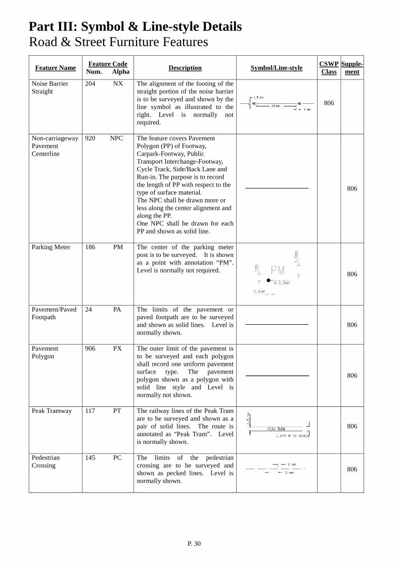
204 NX The alignment of the footing of the straight portion of the noise barrier is to be surveyed and shown by the line symbol as illustrated to the right. Level is normally not required.
806
Non-carriageway Pavement Centerline
920 NPC The feature covers Pavement Polygon (PP) of Footway, Carpark-Footway, Public Transport Interchange-Footway, Cycle Track, Side/Back Lane and Run-in. The purpose is to record the length of PP with respect to the type of surface material. The NPC shall be drawn more or less along the center alignment and along the PP. One NPC shall be drawn for each PP and shown as solid line.
806
Parking Meter 186 PM The center of the parking meter post is to be surveyed. It is shown as a point with annotation “PM”. Level is normally not required.
806
Pavement/Paved Footpath
24 PA The limits of the pavement or paved footpath are to be surveyed and shown as solid lines. Level is normally shown.
806
Pavement Polygon
906 PX The outer limit of the pavement is to be surveyed and each polygon shall record one uniform pavement surface type. The pavement polygon shown as a polygon with solid line style and Level is normally not shown.
806
Peak Tramway 117 PT The railway lines of the Peak Tram are to be surveyed and shown as a pair of solid lines. The route is annotated as “Peak Tram”. Level is normally shown.
806
Pedestrian Crossing
145 PC The limits of the pedestrian crossing are to be surveyed and shown as pecked lines. Level is normally shown.
806
Part III: Symbol & Line-style Details
P. 31
Road & Street Furniture Features
Feature Name
Feature Code Num. Alpha
Description
Symbol/Line-style CSWP
Class Supple-
ment Pedestrian Subway
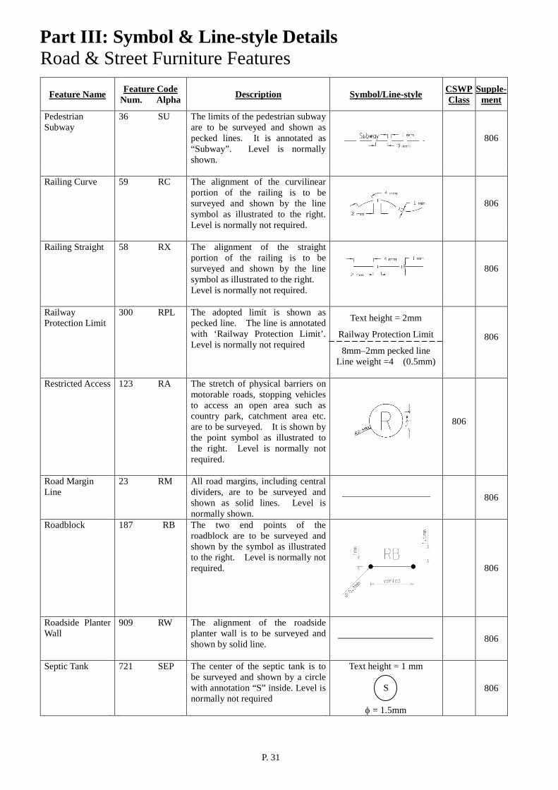
36 SU The limits of the pedestrian subway are to be surveyed and shown as pecked lines. It is annotated as “Subway”. Level is normally shown.
806
Railing Curve 59 RC The alignment of the curvilinear
portion of the railing is to be surveyed and shown by the line symbol as illustrated to the right. Level is normally not required.
806
Railing Straight 58 RX The alignment of the straight
portion of the railing is to be surveyed and shown by the line symbol as illustrated to the right. Level is normally not required.
806
Railway Protection Limit
300 RPL The adopted limit is shown as pecked line. The line is annotated with ‘Railway Protection Limit’. Level is normally not required
Text height = 2mm
Railway Protection Limit
8mm–2mm pecked line Line weight =4 (0.5mm)
806
Restricted Access 123 RA The stretch of physical barriers on
motorable roads, stopping vehicles to access an open area such as country park, catchment area etc. are to be surveyed. It is shown by the point symbol as illustrated to the right. Level is normally not required.
806
Road Margin Line
23 RM All road margins, including central dividers, are to be surveyed and shown as solid lines. Level is normally shown.
806
Roadblock 187 RB The two end points of the roadblock are to be surveyed and shown by the symbol as illustrated to the right. Level is normally not required.
806
Roadside Planter Wall
909 RW The alignment of the roadside planter wall is to be surveyed and shown by solid line.
806
Septic Tank 721 SEP The center of the septic tank is to be surveyed and shown by a circle with annotation “S” inside. Level is normally not required
Text height = 1 mm
S
φ = 1.5mm
806

Part III: Symbol & Line-style Details
P. 32
Road & Street Furniture Features
Feature Name
Feature Code Num. Alpha
Description
Symbol/Line-style CSWP
Class Supple-
ment Sign Board 12 BB The two end points of the sign
board are to be surveyed and shown by the symbol as illustrated to the right. Level is normally not required.
806
Sign Pole 77 SP The center of the sign pole is to be
surveyed. It is shown as a point with annotation “SP”. Level is normally not required.
806
Slope Planter Wall
910 LW The alignment of the planter wall exceeding 0.5m height on Highway Registered Slopes and Highway Unregistered Slopes is to be surveyed and shown by red solid line.
806
Special Paving Panel
911 SPP The center of the special paving panel is to be surveyed and shown by the point symbol as illustrated. Level is normally not required.
806
Stair/Step Edge 35 SI The limits of stair or step are to be surveyed and shown as solid lines. Level is normally shown.
806
Strategic Route Chainage Marker
916 ECM The center of the strategic route chainage marker is to be surveyed. It is shown as a point with annotation “ECM” as illustrated. Level is normally not required.
806
Street Name Plate
913 SNP The position of the post for single post support or the midpoint of cantilever mount or the midpoint of two posts supporting the street name plate is to be surveyed and shown by the symbol as illustrated. Level is normally not required.
806
Tactile Paving 912 TV The centerline of the tactile paving is to be surveyed and shown by red pecked line.
806
Telephone Kiosk 89 TK The mid-points of the opposite sides of the telephone kiosk are to be surveyed and shown by the symbol as illustrated to the right with orientation defined by the line joining the two surveyed points. Level is normally not required.
806
Part III: Symbol & Line-style Details
P. 33
Road & Street Furniture Features
Feature Name
Feature Code Num. Alpha
Description
Symbol/Line-style CSWP
Class Supple-
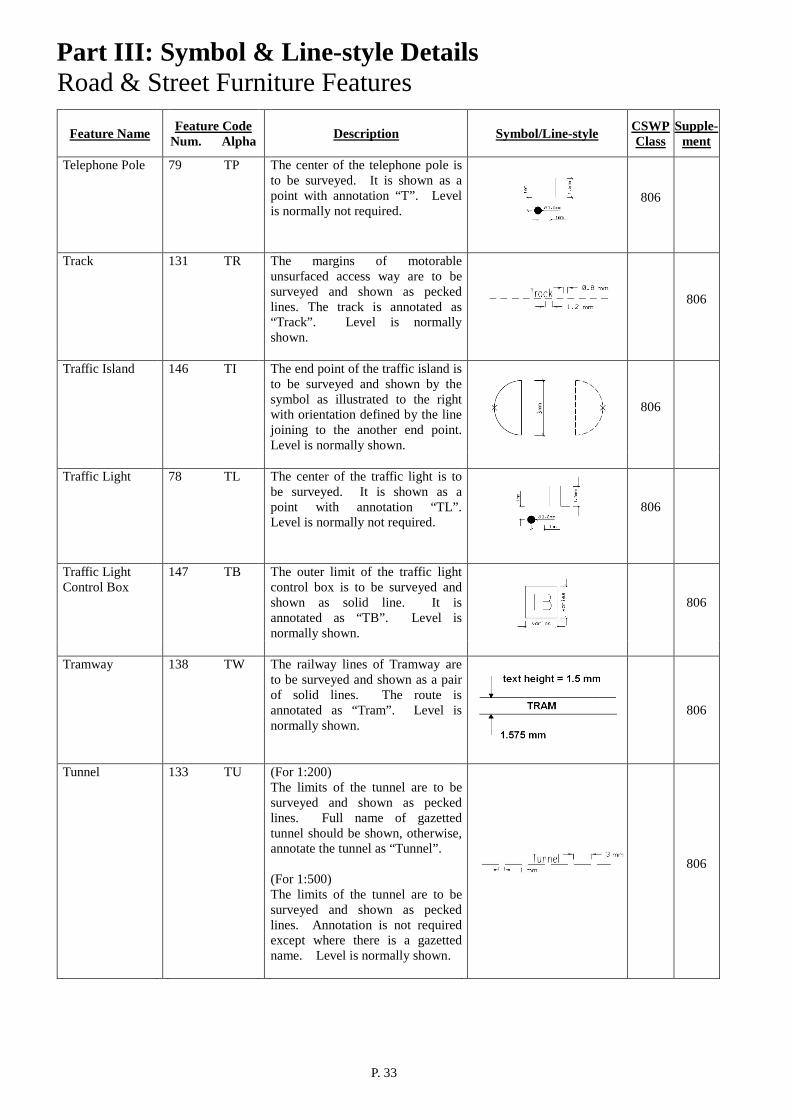
ment Telephone Pole 79 TP The center of the telephone pole is
to be surveyed. It is shown as a point with annotation “T”. Level is normally not required.
806
Track 131 TR The margins of motorable
unsurfaced access way are to be surveyed and shown as pecked lines. The track is annotated as “Track”. Level is normally shown.
806
Traffic Island 146 TI The end point of the traffic island is
to be surveyed and shown by the symbol as illustrated to the right with orientation defined by the line joining to the another end point. Level is normally shown.
806
Traffic Light 78 TL The center of the traffic light is to
be surveyed. It is shown as a point with annotation “TL”. Level is normally not required.
806
Traffic Light Control Box
147 TB The outer limit of the traffic light control box is to be surveyed and shown as solid line. It is annotated as “TB”. Level is normally shown.
806
Tramway 138 TW The railway lines of Tramway are
to be surveyed and shown as a pair of solid lines. The route is annotated as “Tram”. Level is normally shown.
806
Tunnel 133 TU (For 1:200) The limits of the tunnel are to be surveyed and shown as pecked lines. Full name of gazetted tunnel should be shown, otherwise, annotate the tunnel as “Tunnel”. (For 1:500) The limits of the tunnel are to be surveyed and shown as pecked lines. Annotation is not required except where there is a gazetted name. Level is normally shown.
806
Part III: Symbol & Line-style Details
P. 34
Road & Street Furniture Features
Feature Name
Feature Code Num. Alpha
Description
Symbol/Line-style CSWP
Class Supple-
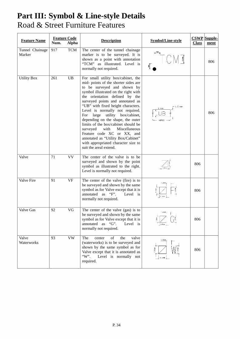
ment Tunnel Chainage Marker
917 TCM The center of the tunnel chainage marker is to be surveyed. It is shown as a point with annotation “TCM” as illustrated. Level is normally not required.
806
Utility Box 261 UB For small utility box/cabinet, the mid- points of the shorter sides are to be surveyed and shown by symbol illustrated on the right with the orientation defined by the surveyed points and annotated as “UB” with fixed height characters. Level is normally not required. For large utility box/cabinet, depending on the shape, the outer limits of the box/cabinet should be surveyed with Miscellaneous Feature code XC or XX, and annotated as “Utility Box/Cabinet” with appropriated character size to suit the areal extend.
806
Valve 71 VV The center of the valve is to be
surveyed and shown by the point symbol as illustrated to the right. Level is normally not required.
806
Valve Fire 91 VF The center of the valve (fire) is to
be surveyed and shown by the same symbol as for Valve except that it is annotated as “F”. Level is normally not required.
806
Valve Gas 92 VG The center of the valve (gas) is to
be surveyed and shown by the same symbol as for Valve except that it is annotated as “G”. Level is normally not required.
806
Valve Waterworks
93 VW The center of the valve (waterworks) is to be surveyed and shown by the same symbol as for Valve except that it is annotated as “W”. Level is normally not required.
806
Part III: Symbol & Line-style Details
P. 35
Road & Street Furniture Features
Feature Name
Feature Code Num. Alpha
Description
Symbol/Line-style CSWP
Class Supple-
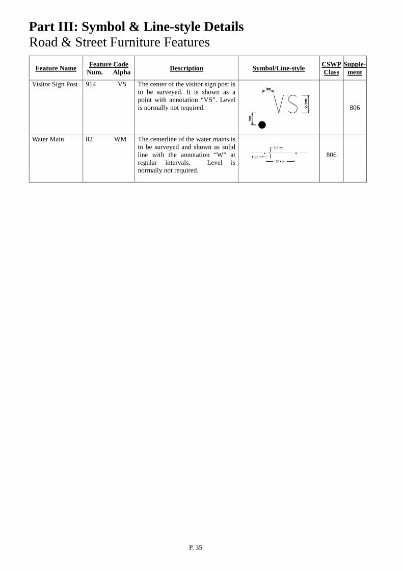
ment Visitor Sign Post 914 VS The center of the visitor sign post is
to be surveyed. It is shown as a point with annotation “VS”. Level is normally not required.
806
Water Main 82 WM The centerline of the water mains is to be surveyed and shown as solid line with the annotation “W” at regular intervals. Level is normally not required.
806

Part III: Symbol & Line-style Details
P. 36
Utilities Features
Feature Name
Feature Code Num. Alpha
Description
Symbol/Line-style CSWP
Class Supple-
ment Blast Deflector 151 BF The position, size and shape of the
blast defector are to be surveyed and shown as pecked line. It is annotated as “BD”. Level is normally shown.
807
Cable Duct
80 CD The centerline of the cable duct, should it be exposed, is to be surveyed. It is shown as solid line with the annotation “CD” at regular intervals. Level is normally not required. (For 1:200) Dimension of the cable duct is to be measured when necessary.
807
Draw Pit 154 DP The position, size and shape of the
draw pit are to be surveyed and shown as solid line. It is annotated as “DP”. Level is normally shown.
807
Electric Pit 155 EI The position, size and shape of the
electric pit are to be surveyed and shown as solid line. It is annotated as “EP”. Level is normally shown.
807
Emergency Helpline
188 EH The center of the emergency helpline is to be surveyed. It is shown as a point with annotation “EH”. Level is normally not required.
807
Fire Hydrant Pit 172 HI The position, size and shape of the fire hydrant pit are to be surveyed and shown as solid line. It is annotated as “H”. Level is normally shown.
807
Floodlight Mast 157 FL The position, size and shape of the
floodlight area are to be surveyed and shown as solid line. It is annotated as “FL”. Level is normally shown.
807
Fuel Hydrant Pit 158 FU The center of the fuel hydrant pit is
to be surveyed and shown as a point with annotation “FU”. Level is normally not required.
807

Part III: Symbol & Line-style Details
P. 37
Utilities Features
Feature Name
Feature Code Num. Alpha
Description
Symbol/Line-style CSWP
Class Supple-
ment Fuel Valve Pit 156 FV The position, size and shape of the
fuel valve pit are to be surveyed and shown as solid line. It is annotated as “FVP”. Level is normally shown.
807
Gas Pipe 81 GP The centerline of the gas pipe,
should it be exposed, is to be surveyed. It is shown as solid line with the annotation “GP” at regular intervals. Level is normally not required. (For 1:200) Dimension of the gas pipe is to be measured when necessary.
807
Lighting Pit 161 LI The position, size and shape of the
lighting pit are to be surveyed and shown as solid line. It is annotated as “LP”. Level is normally shown.
807
Marshalling Platform
163 MP The position, size and shape of the marshalling platform are to be surveyed and shown as pecked line. It is annotated as “V”. Level is normally shown.
807
Nose Tethering Slab
165 NT The position, size and shape of the nose tethering slab are to be surveyed and shown as solid line. It is annotated as “NT”. Level is normally shown.
807
Pillar Box 166 PB The position, size and shape of the
pillar box are to be surveyed and shown as solid line. It is annotated as “PB”. Level is normally shown.
807
Pipeline
119 PP
The centerline of the pipeline is to be surveyed and shown as solid line. Dimension of the pipeline is to be measured and its value annotated. Buried portion of the pipeline will be shown as pecked lines. Level is normally shown.
807

Part III: Symbol & Line-style Details
P. 38
Utilities Features
Feature Name
Feature Code Num. Alpha
Description
Symbol/Line-style CSWP
Class Supple-
ment Plant Watering Tap
189 PWT The center of the plant watering tap is to be surveyed. It is shown as a point with annotation “PWT”. Level is normally not required.
807
Pylon 84 PY
The outer limit of the pylon base is to be surveyed and shown as pecked line. Level is normally not required.
box size varies to fit feature extent 6mm-2mm pecked line
807
Slot Drain 167 SD The position, size and shape of the slot drain are to be surveyed and shown as solid line. It is annotated as “SD”. Ground level and invert level is normally shown.
807
Taxiway Light 162 LT The center of the taxiway light is
to be surveyed and shown as a point with annotation “LI”. Level is normally not required.
807
Taxiway Marking
159 AM The alignment of the taxiway marking is to be surveyed and shown by the line symbol as illustrated to the right. Level is normally shown.
807
Telephone Chamber
169 TC The position, size and shape of the telephone chamber are to be surveyed and shown as solid line. It is annotated as “TC”. Level is normally shown.
807
Transformer Pit 170 TT The position, size and shape of the
transformer pit (for taxiway light) are to be surveyed and shown as solid line. It is annotated as “TP”. Level is normally shown.
807
Unclassified Dot/Point Feature
29 XP The center of the unclassified dot/point feature is to be surveyed. It is shown by a cross as illustrated to the right.
807
Part III: Symbol & Line-style Details
P. 39
Utilities Features
Feature Name
Feature Code Num. Alpha
Description
Symbol/Line-style CSWP
Class Supple-
ment Unclassified Firm Line Structure Curve
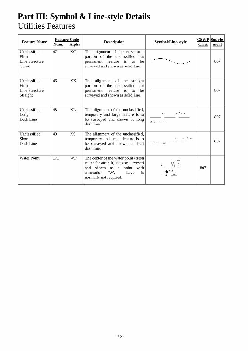
47 XC The alignment of the curvilinear portion of the unclassified but permanent feature is to be surveyed and shown as solid line.
807
Unclassified Firm Line Structure Straight
46 XX The alignment of the straight portion of the unclassified but permanent feature is to be surveyed and shown as solid line.
807
Unclassified Long Dash Line
48 XL The alignment of the unclassified, temporary and large feature is to be surveyed and shown as long dash line.
807
Unclassified Short Dash Line
49 XS The alignment of the unclassified, temporary and small feature is to be surveyed and shown as short dash line.
807
Water Point 171 WP The center of the water point (fresh
water for aircraft) is to be surveyed and shown as a point with annotation `W'. Level is normally not required.
807

Part IV : CSWP Survey Symbol & Line-style Database
P. 40
CSWP (Class 801)
Cell name :
BM Description :
Bench Mark
Cell name : STN
Description : Control Station
Cell name :
TRI Description :
Trigonometrical Station
CSWP (Class 804)
Line styles name : BA
Description : Barriers
Cell name :
LH Description :
Beacon/Light House
Cell name : BS
Description : Boundary Stone
Cell name :
UR Description :
Burial Urn
Cell name: DO
Description : Dolphin
Part IV : CSWP Survey Symbol & Line-style Database
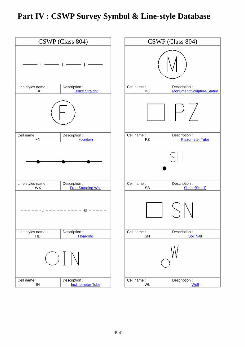
P. 41
CSWP (Class 804)
Line styles name : FX
Description : Fence Straight
Cell name :
FN Description :
Fountain
Line styles name : WX
Description : Free Standing Wall
Line styles name : HD
Description : Hoarding
Cell name : IN
Description : Inclinometer Tube
CSWP (Class 804)
Cell name : MO
Description : Monument/Sculpture/Statue
Cell name : PZ
Description : Piezometer Tube
Cell name : SS
Description : Shrine(Small)
Cell name : SN
Description : Soil Nail
Cell name : WL
Description : Well

Part IV : CSWP Survey Symbol & Line-style Database
P. 42
CSWP (Class 805)
Cell name :
BY Description :
Buoy
Line styles name : HG
Description : Hedge
Line styles name : HW
Description : High Water Mark
Line styles name : SX
Description : Stepped Channel
Line styles name : SR
Description : Stream Course/River
CSWP (Class 805)
Cell name : TG
Description : Tide Gauge
Cell name :
TE Description :
Tree
Line styles name : WR
Description : Vertical Cutting
/Masonry/Retaining Wall
Part IV : CSWP Survey Symbol & Line-style Database
P. 43
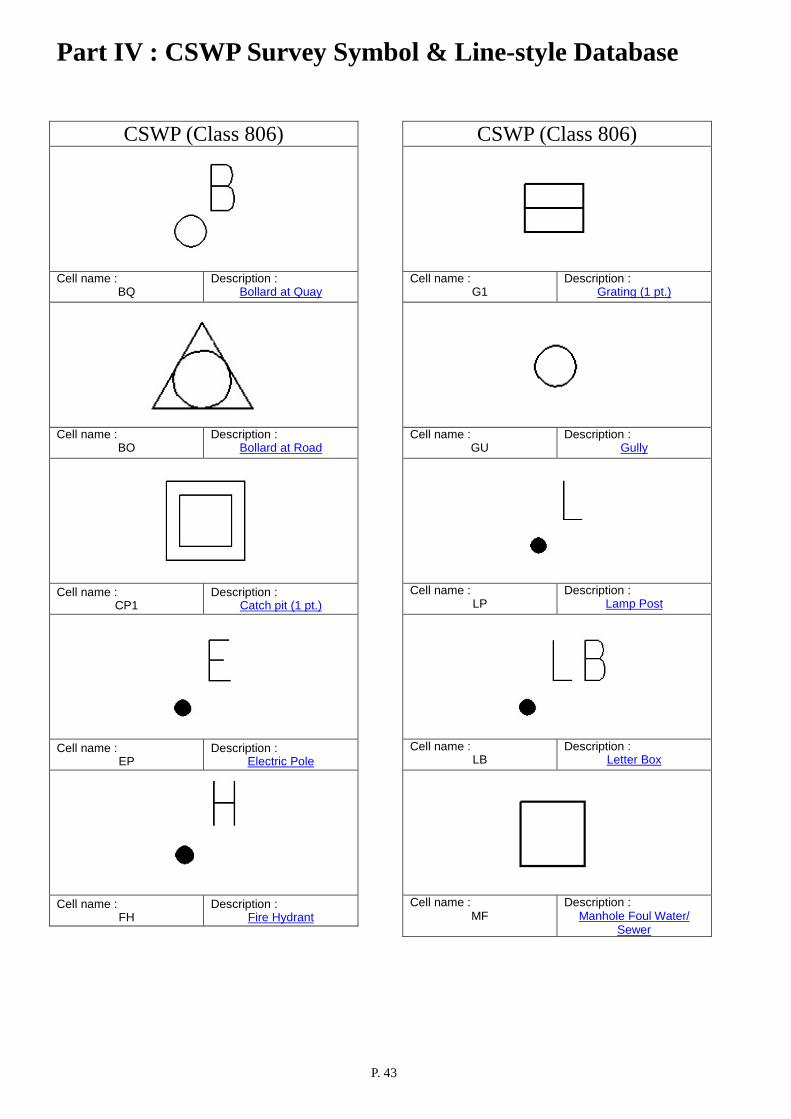
CSWP (Class 806)
Cell name :
BQ Description :
Bollard at Quay
Cell name :
BO Description :
Bollard at Road
Cell name :
CP1 Description :
Catch pit (1 pt.)
Cell name :
EP Description :
Electric Pole
Cell name :
FH Description :
Fire Hydrant
CSWP (Class 806)
Cell name : G1
Description : Grating (1 pt.)
Cell name : GU
Description : Gully
Cell name : LP
Description : Lamp Post
Cell name : LB
Description : Letter Box
Cell name : MF
Description : Manhole Foul Water/
Sewer

Part IV : CSWP Survey Symbol & Line-style Database
P. 44
CSWP (Class 806)
Cell name : MS
Description : Manhole Storm Water
Cell name : MT
Description : Manhole Telephone
Line styles name : MW
Description : Manhole Waterworks
Cell name : ME
Description : Milestone
Line styles name : NX
Description : Noise Barrier Straight
CSWP (Class 806)
Cell name :
RA Description :
Restricted Access
Cell name :
SP Description :
Sign Pole
Cell name :
TP Description :
Telephone Pole
Cell name :
TI Description :
Traffic Island
Cell name : TL
Description : Traffic Light
Part IV : CSWP Survey Symbol & Line-style Database
P. 45
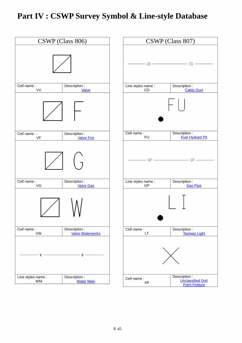
CSWP (Class 806)
Cell name : VV
Description : Valve
Cell name : VF
Description : Valve Fire
Cell name :
VG Description :
Valve Gas
Cell name : VW
Description : Valve Waterworks
Line styles name : WM
Description : Water Main
CSWP (Class 807)
Line styles name : CD
Description : Cable Duct
Cell name :
FU Description :
Fuel Hydrant Pit
Line styles name : GP
Description : Gas Pipe
Cell name : LT
Description : Taxiway Light
Cell name : XP
Description : Unclassified Dot/
Point Feature

Part IV : CSWP Survey Symbol & Line-style Database
P. 46
CSWP (Class 807)
Cell name :
WP Description :
Water Point
Part V : Non-CSWP/Supplementary Survey Symbol & Line-style Database
P. 47
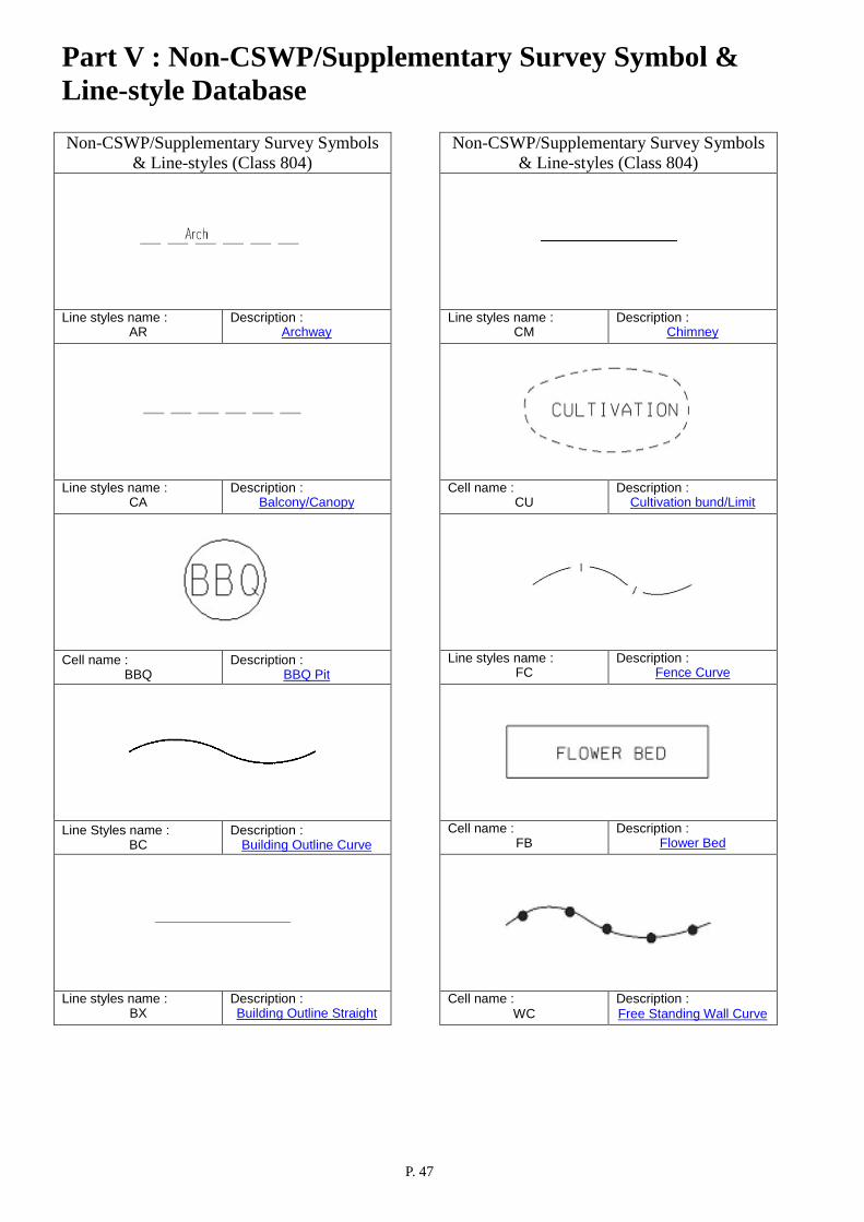
Non-CSWP/Supplementary Survey Symbols & Line-styles (Class 804)
Line styles name :
AR Description :
Archway
Line styles name :
CA Description :
Balcony/Canopy
Cell name :
BBQ Description :
BBQ Pit
Line Styles name : BC
Description : Building Outline Curve
Line styles name : BX
Description : Building Outline Straight
Non-CSWP/Supplementary Survey Symbols & Line-styles (Class 804)
Line styles name : CM
Description : Chimney
Cell name : CU
Description : Cultivation bund/Limit
Line styles name : FC
Description : Fence Curve
Cell name : FB
Description : Flower Bed
Cell name : WC
Description : Free Standing Wall Curve

Part V : Non-CSWP/Supplementary Survey Symbol & Line-style Database
P. 48
Non-CSWP/Supplementary Survey Symbols & Line-styles (Class 804)
Cell name : GA
Description : Gate
Line Styles name : GV
Description : Grave
Line styles name : TA
Description : Oil Tank/Water Tank/
Fuel Tank
Cell name : PV
Description : Pavilion
Line styles name : PTB
Description : Picnic table & bench
Non-CSWP/Supplementary Survey Symbols & Line-styles (Class 804)
Cell name : PL
Description : Platform
Cell name : PD
Description : Podium Line
Cell name : TOI
Description : Portable Toilet
Cell name : RUB
Description : Rubbish Bin
Cell name : RU
Description : Ruin

Part V : Non-CSWP/Supplementary Survey Symbol & Line-style Database
P. 49
Non-CSWP/Supplementary Survey Symbols & Line-styles (Class 804)
Line Styles name : SH
Description : Shrine (Large)
Cell name : TS
Description : Temporary Structure
Line Styles name : WIP
Description : Works in Progress Limit
Non-CSWP/Supplementary Survey Symbols & Line-styles (Class 805)
Line styles name :
BE Description :
Berm
Line styles name :
BD Description :
Boulder/Rock
Cell name : CW
Description : Catchwater
Line Styles name : CC
Description : Channel Curve
Line styles name : CX
Description : Channel Straight
Part V : Non-CSWP/Supplementary Survey Symbol & Line-style Database
P. 50
Non-CSWP/Supplementary Survey Symbols & Line-styles (Class 805)
Line styles name : CL
Description : Cliff
Line styles name :
CV Description :
Culvert
Line styles name : DM
Description : Dam/Weir
Line styles name : DC
Description : Drain Curve
Line styles name : DX
Description : Drain Straight
Non-CSWP/Supplementary Survey Symbols & Line-styles (Class 805)
Line styles name : FO
Description : Fanned Outlet
Line Styles name : JT
Description : Jetty/Pier
Line styles name : LC
Description : Level String Curve
Line styles name : LC
Description : Level String Straight
Line styles name : MA
Description : Marsh/Swamp
Part V : Non-CSWP/Supplementary Survey Symbol & Line-style Database
P. 51
Non-CSWP/Supplementary Survey Symbols & Line-styles (Class 805)
Line styles name : NU
Description : Nullah
Line styles name : PO
Description : Pond/Pool/Moat/
Reservoir/Fountain
Line styles name : QB
Description : Quarry Bottom
Line styles name : QT
Description : Quarry Top
Cell name : P
Description : Random Level Point
(Spot Height)
Non-CSWP/Supplementary Survey Symbols & Line-styles (Class 805)
Cell name : RK
Description : Rocky Area/Group Of
Boulders
Line Styles name : SW
Description : Seawall/Cope Line
Line styles name : SB
Description : Slope Bottom
Line styles name : ST
Description : Slope Top
Line styles name : SC
Description : Stepped Channel Curve
Part V : Non-CSWP/Supplementary Survey Symbol & Line-style Database
P. 52
Non-CSWP/Supplementary Survey Symbols & Line-styles (Class 806)
Line styles name : BK
Description : Barrier Fence
Cell name : BN
Description : Bench
Cell name : BPA
Description : Bicycle Parking Area
Cell name :
BW Description :
Boardwalk
Line styles name : BOL
Description : Bollard Railing
Non-CSWP/Supplementary Survey Symbols & Line-styles (Class 806)
Cell name : BU
Description : Bus Shelter/Terminus
Cell name :
CP2 Description :
Catch Pit (2 pts.)
Line styles name : CO
Description : Column
Line styles name : CY
Description : Covered Walkway
Line styles name : CR
Description : Crash Cushion

Part V : Non-CSWP/Supplementary Survey Symbol & Line-style Database
P. 53
Non-CSWP/Supplementary Survey Symbols & Line-styles (Class 806)
Cell name : DIS
Description : Distance Post
Line styles name : DK
Description : Drop Kerb
Cell name :
ES Description :
Electric Sub-station
Cell name : ET
Description : Electric Transformer
Line styles name : EG
Description : Emergency Gate
Non-CSWP/Supplementary Survey Symbols & Line-styles (Class 806)
Cell name : EM
Description : E&M pit
Line styles name : FP
Description : Footpath (Unpaved)
Line Styles name : BR
Description : Foot/Rail Bridge
Cell name : G2
Description : Grating (2 pts.)
Line styles name : IC
Description : Inspection Chamber

Part V : Non-CSWP/Supplementary Survey Symbol & Line-style Database
P. 54
Non-CSWP/Supplementary Survey Symbols & Line-styles (Class 806)
Line styles name : KC
Description : Kerb Bottom Curve
Line styles name : KX
Description : Kerb Bottom Straight
Line styles name : LR
Description : Light Rail
Cell name : MH
Description : Manhole
Cell name : MH2
Description : Manhole (2 pts.)
Non-CSWP/Supplementary Survey Symbols & Line-styles (Class 806)
Cell name : MF2
Description : Manhole Foul Water/
Sewer ( 2 pts.)
Cell name : MHS
Description : Manhole Structure
Cell name : MT2
Description : Manhole Telephone
(2 pts.)
Cell name : MW2
Description : Manhole Waterworks
(2 pts.)
Line styles name : MTR
Description : Mass Transit Railway

Part V : Non-CSWP/Supplementary Survey Symbol & Line-style Database
P. 55
Non-CSWP/Supplementary Survey Symbols & Line-styles (Class 806)
Line styles name : NC
Description : Noise Barrier Curve
Line styles name : NPC
Description : Non-carriageway Pavement
Centerline
Cell name : PM
Description : Parking Meter
Line styles name : PA
Description : Pavement/Paved Footpath
Line styles name : PX
Description : Pavement Polygon
Non-CSWP/Supplementary Survey Symbols & Line-styles (Class 806)
Line styles name : PT
Description : Peak Tramway
Line styles name : PC
Description : Pedestrian Crossing
Line styles name : SU
Description : Pedestrian Subway
Cell name : RC
Description : Railing Curve
Line styles name : RX
Description : Railing Straight

Part V : Non-CSWP/Supplementary Survey Symbol & Line-style Database
P. 56
Non-CSWP/Supplementary Survey Symbols & Line-styles (Class 806)
Line styles name : RM
Description : Road Margin Line
Cell name : RB
Description : Roadblock
Line styles name : RW
Description : Roadside Planter Wall
Cell name :
SEP Description :
Septic Tank
Cell name : BB
Description : Sign Board
Non-CSWP/Supplementary Survey Symbols & Line-styles (Class 806)
Line styles name : LW
Description : Slope Planter Wall
Cell name : SPP
Description : Special Paving Panel
Line styles name : SI
Description : Stair/Step Edge
Cell name :
ECM
Description : Strategic Route
Chainage Marker
Cell name : SNP
Description : Street Name Plate

Part V : Non-CSWP/Supplementary Survey Symbol & Line-style Database
P. 57
Non-CSWP/Supplementary Survey Symbols & Line-styles (Class 806)
Line styles name : TV
Description : Tactile Paving
Cell name : TK
Description : Telephone Kiosk
Line styles name : TR
Description : Track
Cell name : TB
Description : Traffic Light Control Box
Cell name : TW
Description : Tramway
Non-CSWP/Supplementary Survey Symbols & Line-styles (Class 806)
Line styles name : TU
Description : Tunnel
Cell name : TCM
Description : Tunnel Chainage Marker
Cell name : UB
Description : Utility Box
Cell name :
VS Description :
Visitor Sign Post
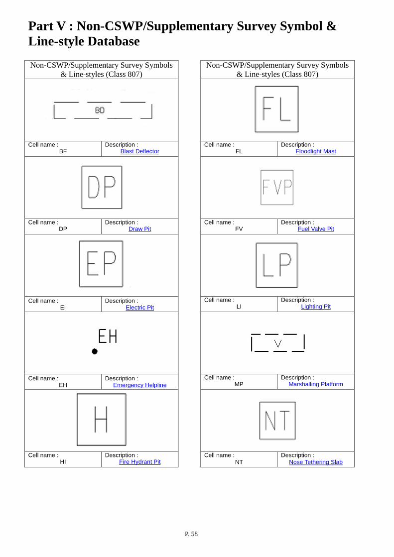
Part V : Non-CSWP/Supplementary Survey Symbol & Line-style Database
P. 58
Non-CSWP/Supplementary Survey Symbols & Line-styles (Class 807)
Cell name : BF
Description : Blast Deflector
Cell name :
DP Description :
Draw Pit
Cell name :
EI Description :
Electric Pit
Cell name : EH
Description : Emergency Helpline
Cell name :
HI Description :
Fire Hydrant Pit
Non-CSWP/Supplementary Survey Symbols & Line-styles (Class 807)
Cell name :
FL Description :
Floodlight Mast
Cell name : FV
Description : Fuel Valve Pit
Cell name :
LI Description :
Lighting Pit
Cell name : MP
Description : Marshalling Platform
Cell name : NT
Description : Nose Tethering Slab

Part V : Non-CSWP/Supplementary Survey Symbol & Line-style Database
P. 59
Non-CSWP/Supplementary Survey Symbols & Line-styles (Class 807)
Cell name : PB
Description : Pillar Box
Line Styles name : PP
Description : Pipeline
Cell name : PWT
Description : Plant Watering Tap
Cell name : PY
Description : Pylon
Cell name : SD
Description : Slot Drain
Non-CSWP/Supplementary Survey Symbols & Line-styles (Class 807)
Line styles name : AM
Description : Taxiway Marking
Cell name : TC
Description : Telephone Chamber
Cell name : TT
Description : Transformer Pit
Line styles name : XC
Description : Unclassified Firm Line
Structure Curve
Line styles name : XX
Description : Unclassified Firm Line
Structure Straight

Part V : Non-CSWP/Supplementary Survey Symbol & Line-style Database
P. 60
Non-CSWP/Supplementary Survey Symbols & Line-styles (Class 807)
Cell name : XL
Description : Unclassified Long
Dash Line
Line styles name : XS
Description : Unclassified Short
Dash Line
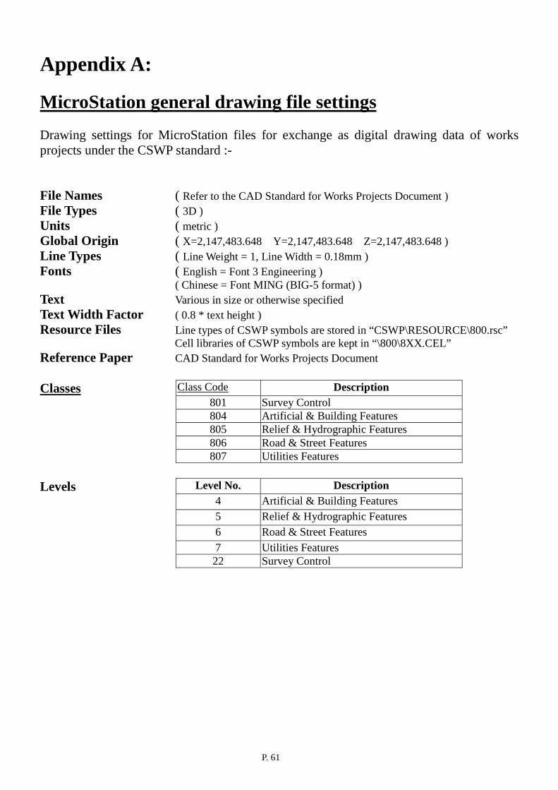
P. 61
Appendix A: MicroStation general drawing file settings Drawing settings for MicroStation files for exchange as digital drawing data of works projects under the CSWP standard :- File Names ( Refer to the CAD Standard for Works Projects Document ) File Types ( 3D ) Units ( metric ) Global Origin ( X=2,147,483.648 Y=2,147,483.648 Z=2,147,483.648 ) Line Types ( Line Weight = 1, Line Width = 0.18mm ) Fonts ( English = Font 3 Engineering )
( Chinese = Font MING (BIG-5 format) ) Text Various in size or otherwise specified Text Width Factor ( 0.8 * text height ) Resource Files Line types of CSWP symbols are stored in “CSWP\RESOURCE\800.rsc”
Cell libraries of CSWP symbols are kept in “\800\8XX.CEL” Reference Paper CAD Standard for Works Projects Document Classes Class Code Description
801 Survey Control 804 Artificial & Building Features 805 Relief & Hydrographic Features 806 Road & Street Features 807 Utilities Features
Levels Level No. Description 4 Artificial & Building Features 5 Relief & Hydrographic Features 6 Road & Street Features 7 Utilities Features 22 Survey Control

P. 62
Appendix B: AutoCAD general drawing file settings Drawing settings for AutoCAD files for exchange as digital drawing data of works projects under the CSWP standard :- File Names ( Refer to the CAD Standard for Works Projects Document ) File Types N/A Units ( Metric ) Global Origin ( X=0 Y=0 Z=0 ) Line Types (Standard AutoCAD line weight settings) Fonts ( English = Romans )
( Chinese = Font MING (BIG-5 format) ) Text Various in size or otherwise specified Text Width Factor ( 0.8 * text height ) Resource Files Line types of CSWP symbols are stored in “CSWP\RESOURCES\800.lin”
Symbol libraries of CSWP symbols are kept in “\800\8XX.DWG” Reference Paper CAD Standard for Works Projects Document Classes Class Code Description
801 Survey Control 804 Artificial & Building Features 805 Relief & Hydrographic Features 806 Road & Street Features 807 Utilities Features
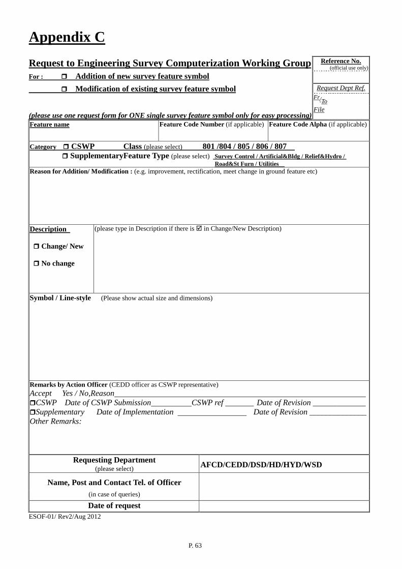
P. 63
Appendix C Request to Engineering Survey Computerization Working Group Reference No.
(official use only)
For : Addition of new survey feature symbol Modification of existing survey feature symbol Request Dept Ref. Fr/To
(please use one request form for ONE single survey feature symbol only for easy processing)
File Feature name Feature Code Number (if applicable) Feature Code Alpha (if applicable)
Category CSWP Class (please select) 801 /804 / 805 / 806 / 807 SupplementaryFeature Type (please select) Survey Control / Artificial&Bldg / Relief&Hydro /
Road&St Furn / Utilities Reason for Addition/ Modification : (e.g. improvement, rectification, meet change in ground feature etc)
Description Change/ New No change
(please type in Description if there is in Change/New Description)
Symbol / Line-style (Please show actual size and dimensions)
Remarks by Action Officer (CEDD officer as CSWP representative) Accept Yes / No,Reason CSWP Date of CSWP Submission CSWP ref _______ Date of Revision _____________ Supplementary Date of Implementation Date of Revision ______________ Other Remarks:
Requesting Department (please select)
AFCD/CEDD/DSD/HD/HYD/WSD
Name, Post and Contact Tel. of Officer
(in case of queries) Date of request
ESOF-01/ Rev2/Aug 2012