Embed Size (px)
Citation preview
Gippsland Water Drafting Specifications
Drafting Specifications for Drawings Produced for Gippsland Water
COR/02/22774
December 15
Gippsland Water
Date Updated: 09 December 2015 Page 2 of 26
© Gippsland Water
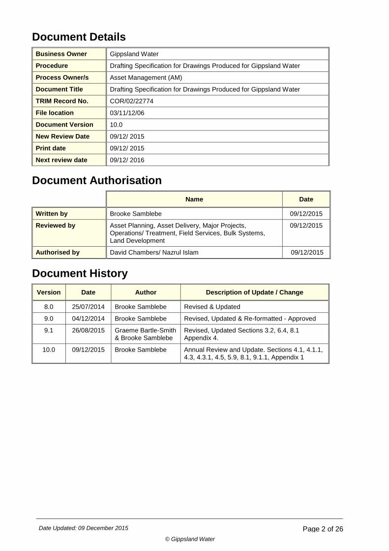
Document Details Business Owner Gippsland Water
Procedure Drafting Specification for Drawings Produced for Gippsland Water
Process Owner/s Asset Management (AM)
Document Title Drafting Specification for Drawings Produced for Gippsland Water
TRIM Record No. COR/02/22774
File location 03/11/12/06
Document Version 10.0
New Review Date 09/12/ 2015
Print date 09/12/ 2015
Next review date 09/12/ 2016
Document Authorisation Name Date
Written by Brooke Samblebe 09/12/2015
Reviewed by Asset Planning, Asset Delivery, Major Projects, Operations/ Treatment, Field Services, Bulk Systems, Land Development
09/12/2015
Authorised by David Chambers/ Nazrul Islam 09/12/2015
Document History Version Date Author Description of Update / Change
8.0 25/07/2014 Brooke Samblebe Revised & Updated
9.0 04/12/2014 Brooke Samblebe Revised, Updated & Re-formatted - Approved
9.1 26/08/2015 Graeme Bartle-Smith & Brooke Samblebe
Revised, Updated Sections 3.2, 6.4, 8.1 Appendix 4.
10.0 09/12/2015 Brooke Samblebe Annual Review and Update. Sections 4.1, 4.1.1, 4.3, 4.3.1, 4.5, 5.9, 8.1, 9.1.1, Appendix 1
Date Updated: 09 December 2015 Page 3 of 26
© Gippsland Water
DRAFTING SPECIFICATION FOR DRAWINGS PRODUCED FOR
GIPPSLAND WATER
1. OVERVIEW ............................................................................................................................... 6
2. INTRODUCTION ............................................................................................................................... 6
3. COMPLIANCE WITH APPROPRIATE STANDARDS ....................................................................... 6
3.1 AUSTRALIAN STANDARDS .......................................................................................................................... 7
3.2 WATER SERVICES ASSOCIATION OF AUSTRALIA CODES ..................................................................... 7
3.3 GIPPSLAND WATER STANDARD & TYPICAL DRAWINGS ........................................................................ 7
3.4 NON-CONFORMING DRAWINGS ................................................................................................................ 7
3.5 SYMBOL DRAWING STANDARDS ............................................................................................................... 8
4. GIPPSLAND WATER ACCEPTANCE OF DRAWINGS.................................................................... 8
4.1 ACCEPTED 2D DRAWING FILE FORMATS ...................................................................................................... 8
4.1.1 MULTI-PAGE 2D DRAWINGS .......................................................................................................................... 8
4.2 ACCEPTED 3D DRAWING FILE FORMATS ...................................................................................................... 9
4.3 SUBMITTAL OF COMPLETED DRAWINGS TO GIPPSLAND WATER ............................................................ 9
4.3.1 AS-CONSTRUCTED P&ID SUBMITTAL ........................................................................................................ 9
4.4 DRAWING FILE TYPES REQUIRED BY GIPPSLAND WATER ...................................................................... 10
4.5 USE OF CROSS REFERENCING OR REFERENCE FILES ............................................................................ 11
4.6 FILE LAYER/ LEVEL STRUCTURE ................................................................................................................... 11
4.7 KEY INDEX SHEET / DRAWING INDEX ........................................................................................................... 11
4.8 AERIAL IMAGERY ............................................................................................................................................. 12
5. GIPPSLAND WATER DRAWING SHEET TEMPLATE & INFORMATION ..................................... 12
5.1. STANDARD GIPPSLAND WATER DRAWING BORDER ................................................................................ 12
6. GIPPSLAND WATER DRAWING STYLE & FORMAT REQUIREMENTS ...................................... 16
6.1 FONT .................................................................................................................................................................. 16
6.2 STANDARD DRAWING SHEETS ...................................................................................................................... 16
6.3 DRAWING SCALES ........................................................................................................................................... 16
6.4 LINE STYLES, COLOURS AND PENTABLES .................................................................................................. 17
6.4.1 Line Styles & Colour Prints for Survey ...................................................................................... 17
6.4.2 Line Styles and Colour Prints for Process and Instrumentation Diagrams (P&ID) ..................... 18
6.4.3 Line Styles and Black & White Prints ........................................................................................ 18
6.5 SPECIAL PURPOSE DRAWINGS ..................................................................................................................... 19
7. SPECIFIC REQUIREMENTS FOR DRAWING DISCIPLINE ........................................................... 19
8. SPECIFIC REQUIREMENTS FOR GIPPSLAND WATER DEPARTMENTS ................................... 20
9. AMIS DRAWING MANAGEMENT PROCESSES ........................................................................... 21
9.1 NEW DRAWINGS .............................................................................................................................................. 21
9.1.1 New Drawings- Land Development ......................................................................................... 22
9.2 EXISTING DRAWING UPDATES ...................................................................................................................... 22
Date Updated: 09 December 2015 Page 4 of 26
© Gippsland Water
9.2.1 Check Out ................................................................................................................................ 22
9.2.2 Revision - Major Projects & Minor Projects ............................................................................... 22
9.2.2.1 Major Projects ....................................................................................................................... 23
9.2.2.2 Minor Projects ....................................................................................................................... 24
9.3 REVISION IDENTIFICATION ............................................................................................................................. 24
9.3.1 Revision Clouding for Existing Drawings .................................................................................. 24
9.3.2 Hold .......................................................................................................................................... 25
9.4.1 SUPERSEDING DRAWINGS ................................................................................................... 25
9.4.2 DEMOLISHED SITES & DRAWINGS ....................................................................................... 25
9.4.3 ARCHIVING DRAWINGS ......................................................................................................... 26
10. DRAWING ETIQUETTE ................................................................................................................ 26
10.1 CONVERSION OF DRAWING FILE FORMATS ............................................................................................. 26
11. QUALITY ASSURANCE ............................................................................................................... 27
11.1 DRAWING COMPLIANCE ............................................................................................................................... 27
11.2 SCHEDULED AUDITING ................................................................................................................................. 27
12. ASSISTANCE TO DRAWING SUPPLIERS ................................................................................... 27
14. FURTHER INFORMATION ............................................................................................................ 28
APPENDIX 1 – GW DRAWINGS TRANSMITTAL_FINAL DEC 2015 ........................................................ 29
(EXCEL SPREADSHEET) ................................................................................................................... 29
APPENDIX 2 -- DRAWINGS COMPLIANCE CHECKLIST ..................................................................... 30
[FOR CONSULTANTS’ AND CONTRACTORS’ USE] ............................................................................................. 30
APPENDIX 3 – VIC ROADS FIELD CODING ...................................................................................... 31
APPENDIX 4 – GIPPSLAND WATER STANDARD AND TYPICAL DRAWINGS ............................... 33

Date Updated: 09 December 2015 Page 5 of 26
© Gippsland Water
Please Note:
It is the responsibility of all persons involved in the production or modification of drawings for Gippsland Water to ensure they have the latest drafting specifications and standard drawing borders. All are updated periodically.
For the latest information you should either contact Gippsland Water directly or download the latest files from:
www.gippswater.com.au
Date Updated: 09 December 2015 Page 6 of 35
© Gippsland Water.
1. OVERVIEW Gippsland Water drawings were previously managed by Gippsland Water’s Asset Delivery department. Since August 2013, drawing management is now controlled by Gippsland Water’s AMIS department (Asset Management Information System) as drawing information is critical to Asset Management. This document will be reviewed on a regular basis to manage improvements made to Gippsland Water’s drawing management system.
The aim of this document is to cover the requirements for drawings produced for Gippsland Water. Drawings are produced through a variety of work phases including engineered design, site inspections, safety and survey.
2. INTRODUCTION It is the responsibility of the persons involved in the production or modification of drawings for Gippsland Water to ensure they have the latest drafting specification and drawing borders. Documents are available for download on Gippsland Water’s website www.gippswater.com.au.
Gippsland Water maintains a drawing management system through an electronic document management system (TRIM). Within this system is stored the Computer Aided Drafting (CAD) file and Portable Document Format (PDF) file for all drawings which have not been stored as scanned images. The PDF files are required as the viewing file by this system as they represent the final printed drawing.
Any drawing submitted to Gippsland Water for inclusion into the drawing management system may be audited for compliance with the requirements of this specification. New drawings produced for Gippsland Water, that are non-conforming and do not comply with this drafting specification will be returned for rectification of all non-conformances at the drafting providers expense, and will be re-audited prior to acceptance into the drawings management system.
The importance of the drawing information retained by Gippsland Water cannot be understated, be it preliminary design or as-constructed information. Gippsland Water’s electronic document management system (TRIM) and Geographic Information System (GIS) are consistently updated with current information, and is available to all Gippsland Water employees, consultants and contractors.
Contractors engaged in works for Gippsland Water are to maintain accurate information and uphold the Codes of Conduct for their respective profession. All work is to comply with the appropriate Australian Standards, Occupational Health & Safety Act and the Gippsland Water’s drafting and contractual requirements.
3. COMPLIANCE WITH APPROPRIATE STANDARDS This section identifies relevant Australian Standards and Gippsland Water specific standards, which shall be used in conjunction with this document when producing drawings for Gippsland Water.
Where there is conflicting or incomplete drafting requirements between standards the following order of precedence shall apply:
1. Project specific drafting requirements
2. Gippsland Water Drafting Specifications (this document)
3. Drafting requirements in WSAA codes
4. Drafting requirements in the Australian Standards
Date Updated: 09 December 2015 Page 7 of 35
© Gippsland Water.
3.1 AUSTRALIAN STANDARDS
All drawings shall comply where applicable with the latest most recent Australian Standards, including amendments :
• AS 1100 part 101: Technical Drawing- General Principles
• AS 1100 part 201: Technical Drawing- Mechanical Engineering Drawing
• AS 1100 part 301: Technical Drawing- Architectural Drawing
• AS 1100 part 401: Technical Drawing- Engineering Survey and Design Drawing
• AS 1100 part 501: Technical Drawing- Structural Engineering Drawing
All electrical/telemetry drawings shall also comply with the following Australian Standards:
• AS 1102 parts 101: Graphical Symbols for Electrotechnical Documentation
• AS/NZ 1102 parts 102 to 111: Graphical Symbols for Electrotechnical Documentation
• AS/NZ 4383.1: Electrotechnology - General Requirements
• AS/NZ 4383.2: Electrotechnology - Function-Oriented Diagrams
• AS/NZ 4383.3: Electrotechnology - Connection Diagrams, Tables and Lists
3.2 WATER SERVICES ASSOCIATION OF AUSTRALIA CODES
Gippsland Water adopts the Water Services Association of Australia (WSAA) Codes, identifying both water and sewage technical requirements to efficiently and safely design and build assets to deliver water and wastewater services sustainably, for current and future generations. Gippsland Water also has supplements to the code. Refer to the Gippsland Water Supplement to WSA 03-2011-3.1 Water Supply Code of Australia MRWA Edition 2015. Gippsland Water COR/14/107091.
The Sewer Code WSA 02-2014 is ‘under preparation’ and will be advised
3.3 GIPPSLAND WATER STANDARD & TYPICAL DRAWINGS
Gippsland Water has standard drawing requirements and provides example drawings for guidance on drafting expectations. Appendix 4 contains a list of standard and example drawings. Contact the Gippsland Water AMIS RMO for hardcopy and electronic copies.
Existing Gippsland Water drawings may have been prepared to previous standards and may not comply with these specifications. However, all new drawings and major updates to existing drawings shall comply with these specifications.
3.4 NON-CONFORMING DRAWINGS
The drafting provider shall request clarification from the Gippsland Water Project RO for update of past drawings that do not comply with the current Gippsland Water Drafting Specifications and Australian Standards. The drafting provider shall discuss each project and associated updates to past drawings with the Gippsland Water Project RO on a case by case basis.
Date Updated: 09 December 2015 Page 8 of 35
© Gippsland Water.
3.5 SYMBOL DRAWING STANDARDS
The drafting provider shall request clarification from the Gippsland Water Project RO for requirements to update past drawings with current drawing symbols.
Drafting protocol is to use the existing drawing symbols used on the drawing. The Gippsland Water Project RO will determine if the updates to the drawing shall be re-drawn with new symbols standards or if the existing drawing symbols will be used. The drafting provider shall discuss each project and associated updates to past drawings with the Gippsland Water Project RO on a case by case basis.
Symbols for layout drawings shall comply with WSAA Codes:
• Water: WSA03-2011-3.1, MRWA Edition and standard drawing MRWA-W-100
• Sewer: WSA-02-1999
Symbols for Gippsland Water P&ID drawings shall comply with Gippsland Water drawing A1-58517.
4. GIPPSLAND WATER ACCEPTANCE OF DRAWINGS Drafting contractors and consultants must prepare all drawings within the guidelines provided within this Drafting Specification for Drawings Produced for Gippsland Water.
Drawings will be provided to the Gippsland Water Project RO for compliance checking against the drafting specifications and approval given prior to payment.
Gippsland Water accepts both 2D and 3D drawings and models. The Gippsland Water Project RO will determine what drawings are required for the project.
4.1 ACCEPTED 2D DRAWING FILE FORMATS
All new drawings prepared shall be produced using a Computer Aided Drafting (CAD) system. The acceptable file format is either Microstation (Version 8+) or AutoCAD (Release 2004 to 2012). A PDF must always accompany the CAD file.
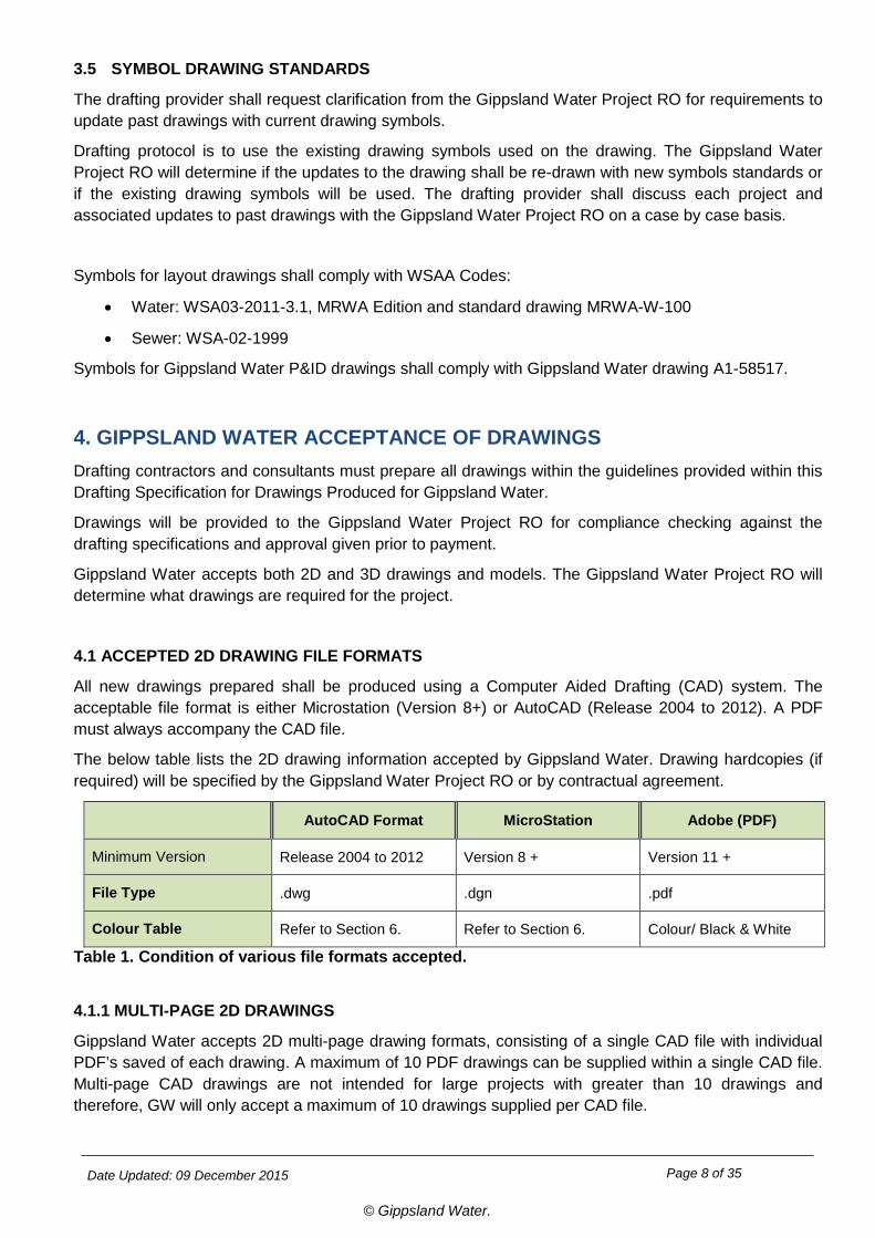
The below table lists the 2D drawing information accepted by Gippsland Water. Drawing hardcopies (if required) will be specified by the Gippsland Water Project RO or by contractual agreement.
AutoCAD Format MicroStation Adobe (PDF)
Minimum Version Release 2004 to 2012 Version 8 + Version 11 +
File Type .dwg .dgn .pdf
Colour Table Refer to Section 6. Refer to Section 6. Colour/ Black & White
Table 1. Condition of various file formats accepted.
4.1.1 MULTI-PAGE 2D DRAWINGS
Gippsland Water accepts 2D multi-page drawing formats, consisting of a single CAD file with individual PDF’s saved of each drawing. A maximum of 10 PDF drawings can be supplied within a single CAD file. Multi-page CAD drawings are not intended for large projects with greater than 10 drawings and therefore, GW will only accept a maximum of 10 drawings supplied per CAD file.
Date Updated: 09 December 2015 Page 9 of 35
© Gippsland Water.
4.2 ACCEPTED 3D DRAWING FILE FORMATS
Gippland Water accepts 3D models using the INVENTOR software. Gippsland Water is new to 3D models and drawings and it is the responsibility of the Gippsland Water Project/ Responsible Officer to determine if 3D drawings and associated model are required for the project.
Gippsland Water has internal processes to manage and store 3D drawings and models.
4.3 SUBMITTAL OF COMPLETED DRAWINGS TO GIPPSLAND WATER
Drawings produced for Gippsland Water must be accompanied by a Gippsland Water electronic drawing transmittal (excel spreadsheet) detailing information of the drawings produced. This transmittal is used to upload drawings, refer to the Help Tab for instructions to complete the electronic drawing transmittal. The transmittal can be obtained from Gippsland Water’s website under Tenders- Drawing Specifications.
The drawing files must be individually saved and named as the Gippsland Water drawing number. For example:
• A1-12345.dgn or A1-12345.dwg
• A1-12345.pdf
All drawings are to be saved in a single folder titled as the project name.
The drawings can be submitted to Gippsland Water via:
• Email containing a zipped attachment. (Not greater than 8MB in size)
• Electronic DataBox (Files greater than 8MB)
Contact the AMIS Records Management Officer to provide access to this service. Refer to Section 14. FURTHER INFORMATION.
• Compact Disc (CD) ROM or USB
• All transfer media (Email/CD/USB) is to be labelled with the following information.
o Contractor’s/ Consultants name
o Contractor’s/ Consultants reference
o Date of issue
o GW Responsible Officer/ Project Officer
4.3.1 AS-CONSTRUCTED P&ID SUBMITTAL
Process & Instrumentation Diagrams (P&ID) contain background information with links to Gippsland Water Asset Information, therefore require specific guidelines. Gippsland Water will only accept As-Constructed P&ID drawings that comply with the following:
• Gippsland Water accepts both MicroStation (DGN) and AutoCAD (DWG) formats for new P&ID drawings, with an electronic Asset (Tag) List in Microsoft excel version 2010.
• Updates to existing P&ID CAD file formats shall remain in their current CAD format. If the current CAD version is in MicroStation (DGN), then it must remain in MicroStation (DGN) it cannot be converted to AutoCAD (DWG). No conversion of existing P&ID’s will be accepted due to loss of data and corrupt files.
• The CAD file must be accompanied with an Asset (Tag) List in Microsoft excel version 2010.
Date Updated: 09 December 2015 Page 10 of 35
© Gippsland Water.
• The CAD file must be accompanied with a PDF (requirement for all drawings).
• All P&ID’s shall only show Gippsland Water asset tags. Where P&ID’s are supplied with vendor packages, the asset tagging shall use the Gippsland Water asset tagging system, where possible.
• The P&ID shall be drawn with flows paths from left to right and top to bottom where practical.
• P&ID’s shall be split into sheets (Sheet 1 of 2, Sheet 2 of 2) if the drawing has excessive information resulting in difficulty reading the drawing. If this occurs the drawings shall be titled Sheet 1 of 2 and Sheet 2 of 2, etc.
• Appendix 4 refers to the P&ID symbols sheet that drawings supplied to Gippsland Water shall comply with for new and existing drawings.
4.4 DRAWING FILE TYPES REQUIRED BY GIPPSLAND WATER
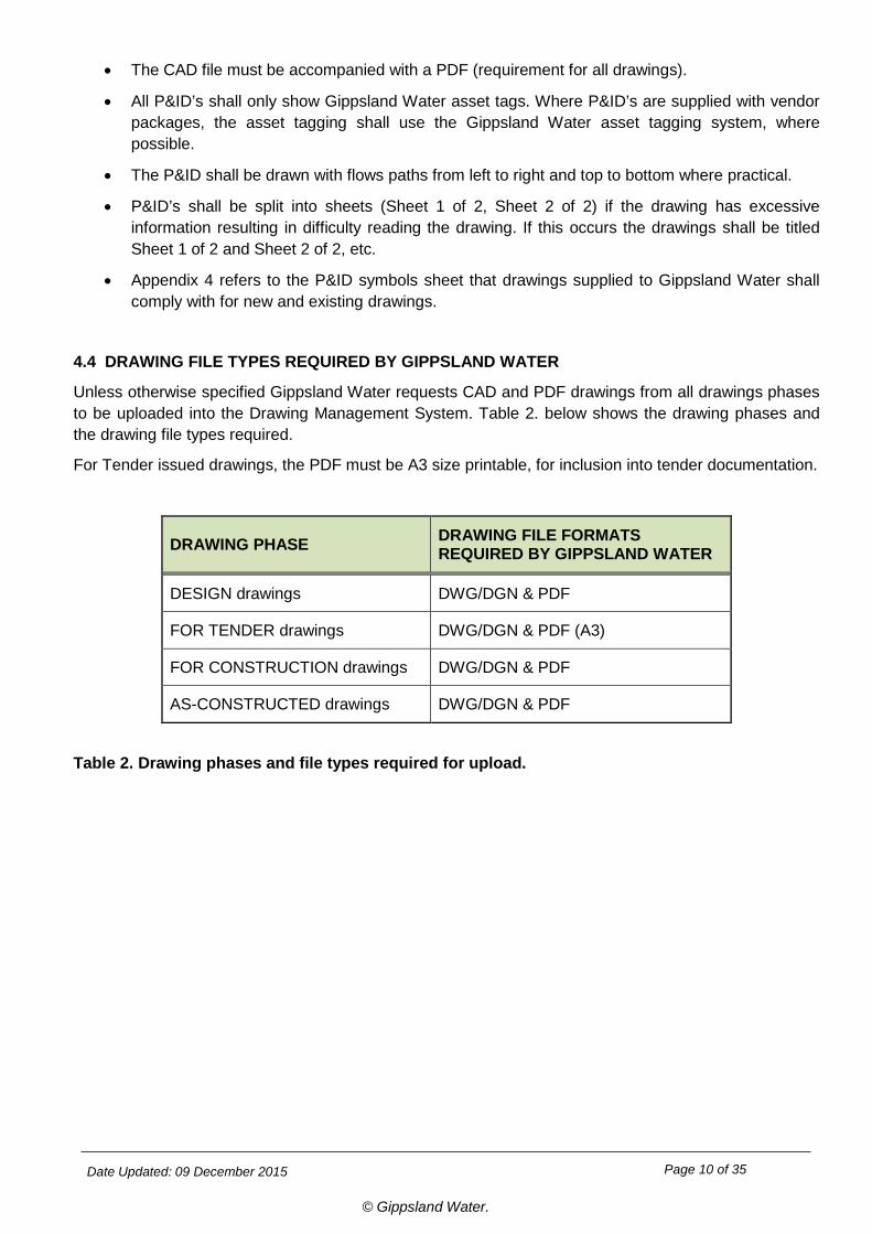
Unless otherwise specified Gippsland Water requests CAD and PDF drawings from all drawings phases to be uploaded into the Drawing Management System. Table 2. below shows the drawing phases and the drawing file types required.
For Tender issued drawings, the PDF must be A3 size printable, for inclusion into tender documentation.
DRAWING PHASE DRAWING FILE FORMATS REQUIRED BY GIPPSLAND WATER
DESIGN drawings DWG/DGN & PDF
FOR TENDER drawings DWG/DGN & PDF (A3)
FOR CONSTRUCTION drawings DWG/DGN & PDF
AS-CONSTRUCTED drawings DWG/DGN & PDF
Table 2. Drawing phases and file types required for upload.
Date Updated: 09 December 2015 Page 11 of 35
© Gippsland Water.
4.5 USE OF CROSS REFERENCING OR REFERENCE FILES
The use of reference files is an accepted part of creating drawings and especially maps in CAD format. This enables other drawing files to be used as overlays in the production of drawings. However the final CAD file being handed over to Gippsland Water shall where possible, not use cross referencing or reference files. The final CAD file shall contain all of, and only, the information shown on the final plot supplied to Gippsland Water and be as shown in the supplied PDF file.
In particular to Survey Drawings, separate jpg. files shall be saved as the drawing number.jpg (A1-12345.jpg) to be saved with the drawings (A1-12345.dwg/ dgn/ pdf) and included in the Gippsland Water electronic transmittal for upload .
Exceptions may apply where externally referenced files cannot be readily bound into the drawing file. The GW Project RO shall approve the drawings and the AMIS RMO shall ensure the records and future updates can be maintained. In these circumstances, the drawing file and associated cross referencing files shall be grouped together and saved as a zip.file, titled as the drawing number eg, A1-12345.zip
4.6 FILE LAYER/ LEVEL STRUCTURE
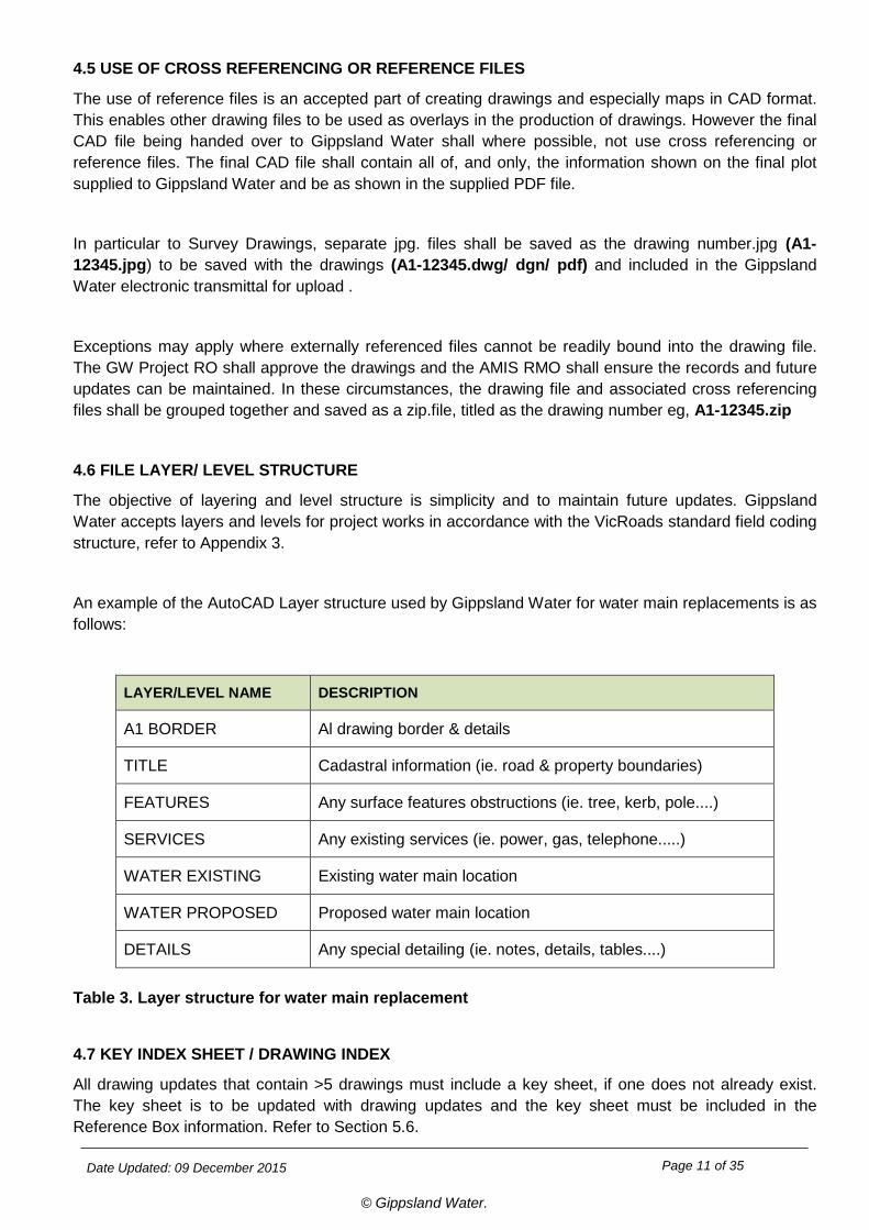
The objective of layering and level structure is simplicity and to maintain future updates. Gippsland Water accepts layers and levels for project works in accordance with the VicRoads standard field coding structure, refer to Appendix 3.
An example of the AutoCAD Layer structure used by Gippsland Water for water main replacements is as follows:
LAYER/LEVEL NAME DESCRIPTION
A1 BORDER Al drawing border & details
TITLE Cadastral information (ie. road & property boundaries)
FEATURES Any surface features obstructions (ie. tree, kerb, pole....)
SERVICES Any existing services (ie. power, gas, telephone.....)
WATER EXISTING Existing water main location
WATER PROPOSED Proposed water main location
DETAILS Any special detailing (ie. notes, details, tables....) Table 3. Layer structure for water main replacement
4.7 KEY INDEX SHEET / DRAWING INDEX
All drawing updates that contain >5 drawings must include a key sheet, if one does not already exist. The key sheet is to be updated with drawing updates and the key sheet must be included in the Reference Box information. Refer to Section 5.6.
Date Updated: 09 December 2015 Page 12 of 35
© Gippsland Water.
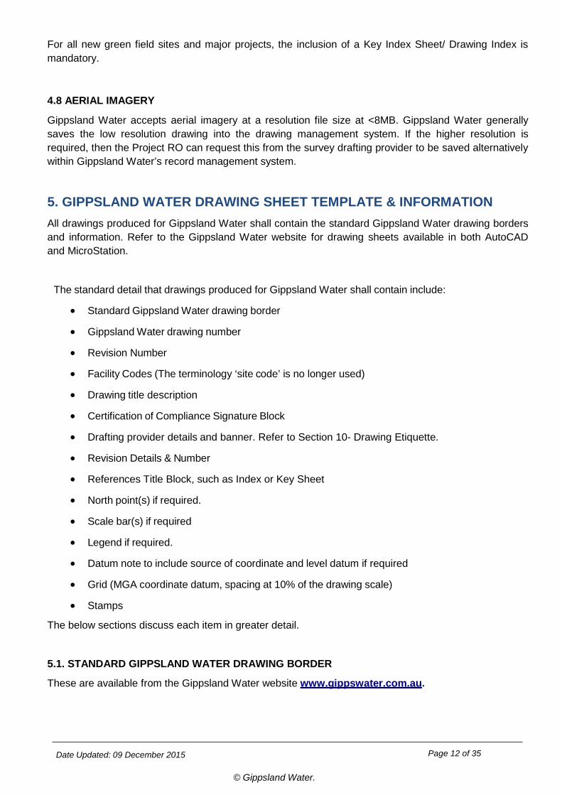
For all new green field sites and major projects, the inclusion of a Key Index Sheet/ Drawing Index is mandatory.
4.8 AERIAL IMAGERY
Gippsland Water accepts aerial imagery at a resolution file size at <8MB. Gippsland Water generally saves the low resolution drawing into the drawing management system. If the higher resolution is required, then the Project RO can request this from the survey drafting provider to be saved alternatively within Gippsland Water’s record management system.
5. GIPPSLAND WATER DRAWING SHEET TEMPLATE & INFORMATION All drawings produced for Gippsland Water shall contain the standard Gippsland Water drawing borders and information. Refer to the Gippsland Water website for drawing sheets available in both AutoCAD and MicroStation.
The standard detail that drawings produced for Gippsland Water shall contain include:
• Standard Gippsland Water drawing border
• Gippsland Water drawing number
• Revision Number
• Facility Codes (The terminology ‘site code’ is no longer used)
• Drawing title description
• Certification of Compliance Signature Block
• Drafting provider details and banner. Refer to Section 10- Drawing Etiquette.
• Revision Details & Number
• References Title Block, such as Index or Key Sheet
• North point(s) if required.
• Scale bar(s) if required
• Legend if required.
• Datum note to include source of coordinate and level datum if required
• Grid (MGA coordinate datum, spacing at 10% of the drawing scale)
• Stamps
The below sections discuss each item in greater detail.
5.1. STANDARD GIPPSLAND WATER DRAWING BORDER
These are available from the Gippsland Water website www.gippswater.com.au.
Date Updated: 09 December 2015 Page 13 of 35
© Gippsland Water.
5.2 GIPPSLAND WATER DRAWING NUMBER, REVISION NUMBER & FACILITY CODE
The Gippsland Water drawing number shall appear in the box provided in the bottom right corner of the drawing sheet. The revision number shall be directly beside the drawing number. The facility code must be provided on the drawing, above the drawing number & revision number in the bottom right corner.
Both Gippsland Water drawing numbers and facility codes are obtained from the Gippsland Water’s Responsible / Project Officer, via the AMIS Records Management Officer. Gippsland Water recommends drawing number requests take into consideration the proposed number of drawings to be produced for the project, and therefore request a batch of drawing numbers to enable sequential numbering, where possible.
The Gippsland Water drawing number, revision number and facility code shall be drawn in green 0.5mm. This text shall be black when provided on the PDF drawing.
5.3 DRAWING TITLE DESCRIPTION
Drawing titles must be verified by the Gippsland Water Project RO. The title shall be centre justified and placed centrally within the drawing title box.
The title of drawings produced must be as follows: 1. First line: site description from the Asset List Structure based on the first two numbers of the Facility
Code number eg, 10 is Warragul-Drouin Water Supply System 2. Second line: more descriptive site description. This can be a common name/title used or naming from
the Asset List Structure based on the alpha letters after the Facility Code number eg, RR is Water Supply / Reticulation
3. Third line: is more flexible with respect to project/ plant/component 4. Fourth line: to specify the drawing contents No two drawings should have the same title, except if it has multiple sheets, eg, Sheet 1 of 2. The following are examples of the drawing titles used by Gippsland Water.
Example 1.
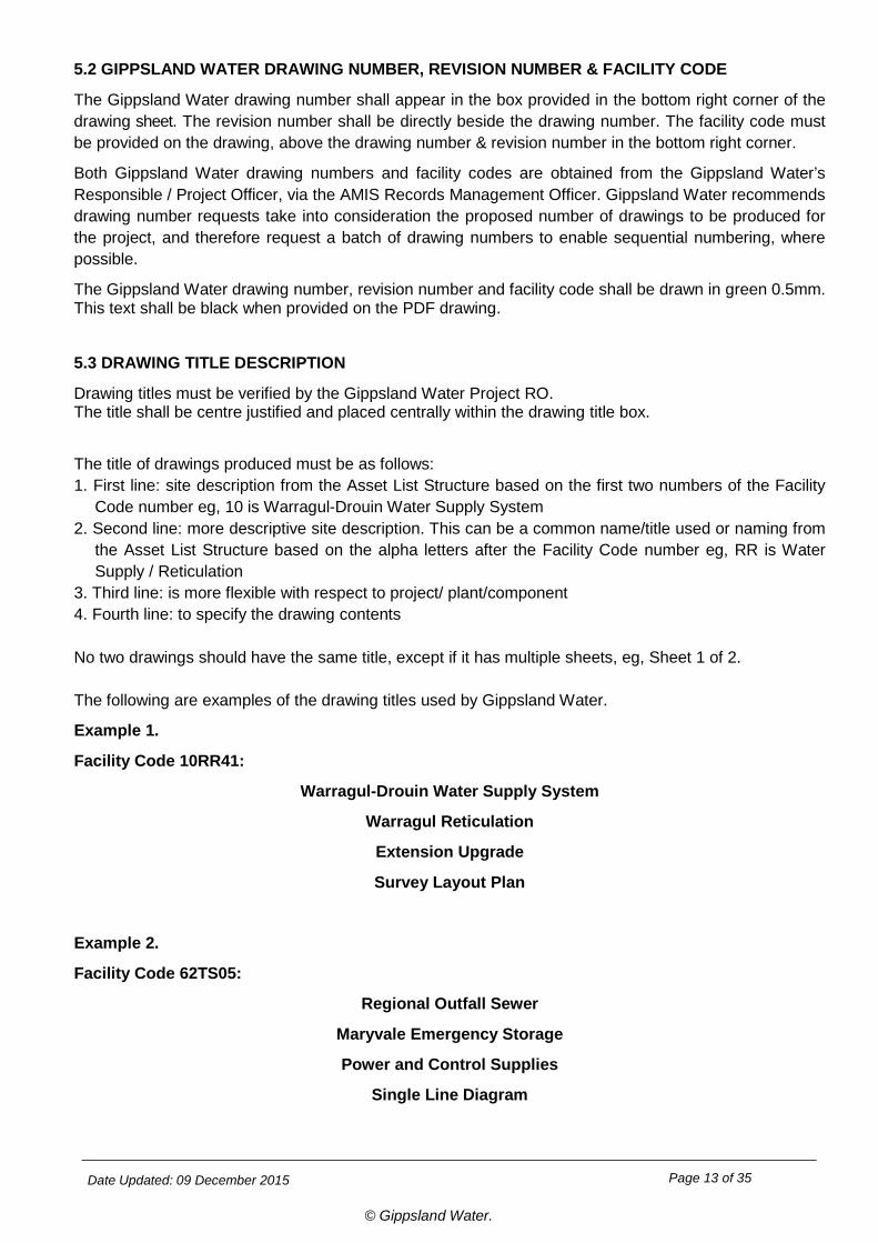
Facility Code 10RR41:
Warragul-Drouin Water Supply System
Warragul Reticulation
Extension Upgrade
Survey Layout Plan
Example 2.
Facility Code 62TS05:
Regional Outfall Sewer
Maryvale Emergency Storage
Power and Control Supplies
Single Line Diagram
Date Updated: 09 December 2015 Page 14 of 35
© Gippsland Water.
The Gippsland Water drawing title description in the title block shall be drawn in red 0.35mm. This text shall be black when provided on the PDF drawing.
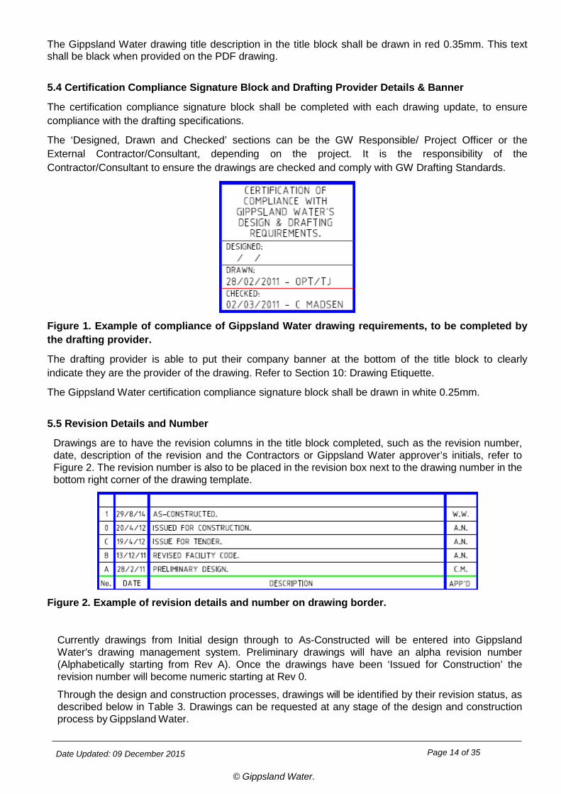
5.4 Certification Compliance Signature Block and Drafting Provider Details & Banner
The certification compliance signature block shall be completed with each drawing update, to ensure compliance with the drafting specifications.
The ‘Designed, Drawn and Checked’ sections can be the GW Responsible/ Project Officer or the External Contractor/Consultant, depending on the project. It is the responsibility of the Contractor/Consultant to ensure the drawings are checked and comply with GW Drafting Standards.
Figure 1. Example of compliance of Gippsland Water drawing requirements, to be completed by the drafting provider.
The drafting provider is able to put their company banner at the bottom of the title block to clearly indicate they are the provider of the drawing. Refer to Section 10: Drawing Etiquette.
The Gippsland Water certification compliance signature block shall be drawn in white 0.25mm.
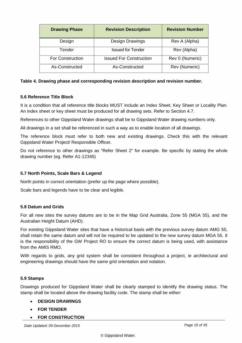
5.5 Revision Details and Number
Drawings are to have the revision columns in the title block completed, such as the revision number, date, description of the revision and the Contractors or Gippsland Water approver’s initials, refer to Figure 2. The revision number is also to be placed in the revision box next to the drawing number in the bottom right corner of the drawing template.
Figure 2. Example of revision details and number on drawing border.
Currently drawings from Initial design through to As-Constructed will be entered into Gippsland Water’s drawing management system. Preliminary drawings will have an alpha revision number (Alphabetically starting from Rev A). Once the drawings have been ‘Issued for Construction’ the revision number will become numeric starting at Rev 0.
Through the design and construction processes, drawings will be identified by their revision status, as described below in Table 3. Drawings can be requested at any stage of the design and construction process by Gippsland Water.
Date Updated: 09 December 2015 Page 15 of 35
© Gippsland Water.
Drawing Phase Revision Description Revision Number
Design Design Drawings Rev A (Alpha)
Tender Issued for Tender Rev (Alpha)
For Construction Issued For Construction Rev 0 (Numeric)
As-Constructed As-Constructed Rev (Numeric)
Table 4. Drawing phase and corresponding revision description and revision number.
5.6 Reference Title Block
It is a condition that all reference title blocks MUST include an Index Sheet, Key Sheet or Locality Plan. An index sheet or key sheet must be produced for all drawing sets. Refer to Section 4.7.
References to other Gippsland Water drawings shall be to Gippsland Water drawing numbers only.
All drawings in a set shall be referenced in such a way as to enable location of all drawings.
The reference block must refer to both new and existing drawings. Check this with the relevant Gippsland Water Project/ Responsible Officer.
Do not reference to other drawings as “Refer Sheet 2” for example. Be specific by stating the whole drawing number (eg. Refer A1-12345)
5.7 North Points, Scale Bars & Legend
North points in correct orientation (prefer up the page where possible).
Scale bars and legends have to be clear and legible.
5.8 Datum and Grids
For all new sites the survey datums are to be in the Map Grid Australia, Zone 55 (MGA 55), and the Australian Height Datum (AHD).
For existing Gippsland Water sites that have a historical basis with the previous survey datum AMG 55, shall retain the same datum and will not be required to be updated to the new survey datum MGA 55. It is the responsibility of the GW Project RO to ensure the correct datum is being used, with assistance from the AMIS RMO.
With regards to grids, any grid system shall be consistent throughout a project, ie architectural and engineering drawings should have the same grid orientation and notation.
5.9 Stamps
Drawings produced for Gippsland Water shall be clearly stamped to identify the drawing status. The stamp shall be located above the drawing facility code. The stamp shall be either:
• DESIGN DRAWINGS
• FOR TENDER
• FOR CONSTRUCTION
Date Updated: 09 December 2015 Page 16 of 35
© Gippsland Water.
• AS-CONSTRUCTED For internal Gippsland Water creation of Standard & Typical Drawings the below stamps shall be used:
• STANDARD TEMPLATE
• TYPICAL DRAWING ONLY
6. GIPPSLAND WATER DRAWING STYLE & FORMAT REQUIREMENTS 6.1 FONT
Lettering conforming with ISO 3098/1 Type B Upright only will be accepted.
In Autocad files the font file to be used is “ISOCP.SHX”.
In MicroStation files the font number to be used is 128. This could be the AutoCAD font file “ISOCP.SHX” imported into the different contractors font.rsc.
For Microstation users, a FONT.rsc (resource library) is available for download from Gippsland Water’s website, containing the accepted font.
The drawing title description in the title block shall be drawn in red 0.35mm. The Gippsland Water drawing number, facility code & revision number shall be drawn in green 0.5mm. . The certification compliance signature block shall be drawn in white 0.25mm Also refer to Section 5. Non-conforming fonts will be accepted for drawings which meet the criteria listed in Section 6.5 (Special Purpose Drawings).
6.2 STANDARD DRAWING SHEETS
Sheet sizes shall be A3, A2 or A1 in accordance with AS 1100.
The drafting provider and GW Project RO are to agree on the preferred drawing sheet size for drawings produced for their specific project, to ensure the drawing detail is legible. The drafting provider needs to advise Gippsland Water of the drawing paper size when requesting drawing numbers from Gippsland Water.
A copy of Gippsland Water’s standard drawing sheets are available for download from the Gippsland Water website www.gippswater.com.au in both AutoCAD and Microstation formats.
6.3 DRAWING SCALES
All drawing scales are to conform to the relevant Australian Standards. All scales stated on a drawing shall be accompanied by a scale bar conforming to AS 1100 Part 101 –1992. Drawings shall be produced in the following scales, unless otherwise instructed by the Gippsland Water Project Responsible Officer.
PLAN
1:250 or 1:500 – Urban Areas
1:500, 1:1000 or 1:2000 – Rural Area
LONGITUDINAL SECTIONS
1:250, 1:500, 1:1000 or 1:2000 - Horizontal Scale.
Date Updated: 09 December 2015 Page 17 of 35
© Gippsland Water.
The vertical exaggeration is to be either 5:1 or 10:1 of the horizontal scale. Cross Sections 1:100 – Horizontal Scale The vertical exaggeration is to be either 1:1 or 2:1 of the horizontal scale.
Where water and wastewater assets are of an intricate nature, or proposed in areas where there are numerous or nearby services or features, enlargements of those works shall be drawn at a scale of 1:100, 1:25 and/or 1:20, as agreed by the GW Project RO.
6.4 LINE STYLES, COLOURS AND PENTABLES
Drawings produced for Gippsland Water have custom line styles, described below. Generally, colour printouts are preferred for survey and P&ID drawings, where as other disciplines such as mechanical or civil generally print to black and white. Gippsland Water allows colour prints to the below specifications.
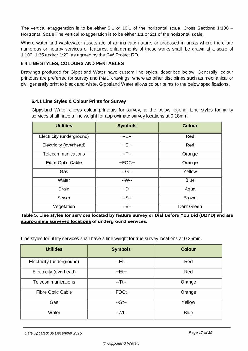
6.4.1 Line Styles & Colour Prints for Survey
Gippsland Water allows colour printouts for survey, to the below legend. Line styles for utility services shall have a line weight for approximate survey locations at 0.18mm.
Utilities Symbols Colour
Electricity (underground) --E-- Red
Electricity (overhead) __E__ Red
Telecommunications --T-- Orange
Fibre Optic Cable __FOC__ Orange
Gas --G-- Yellow
Water --W-- Blue
Drain --D-- Aqua
Sewer --S-- Brown
Vegetation --V-- Dark Green
Table 5. Line styles for services located by feature survey or Dial Before You Did (DBYD) and are approximate surveyed locations of underground services.
Line styles for utility services shall have a line weight for true survey locations at 0.25mm.
Utilities Symbols Colour
Electricity (underground) --Et-- Red
Electricity (overhead) __Et__ Red
Telecommunications --Tt-- Orange
Fibre Optic Cable __FOCt__ Orange
Gas --Gt-- Yellow
Water --Wt-- Blue
Date Updated: 09 December 2015 Page 18 of 35
© Gippsland Water.
Drain --Dt-- Aqua
Sewer --St-- Brown
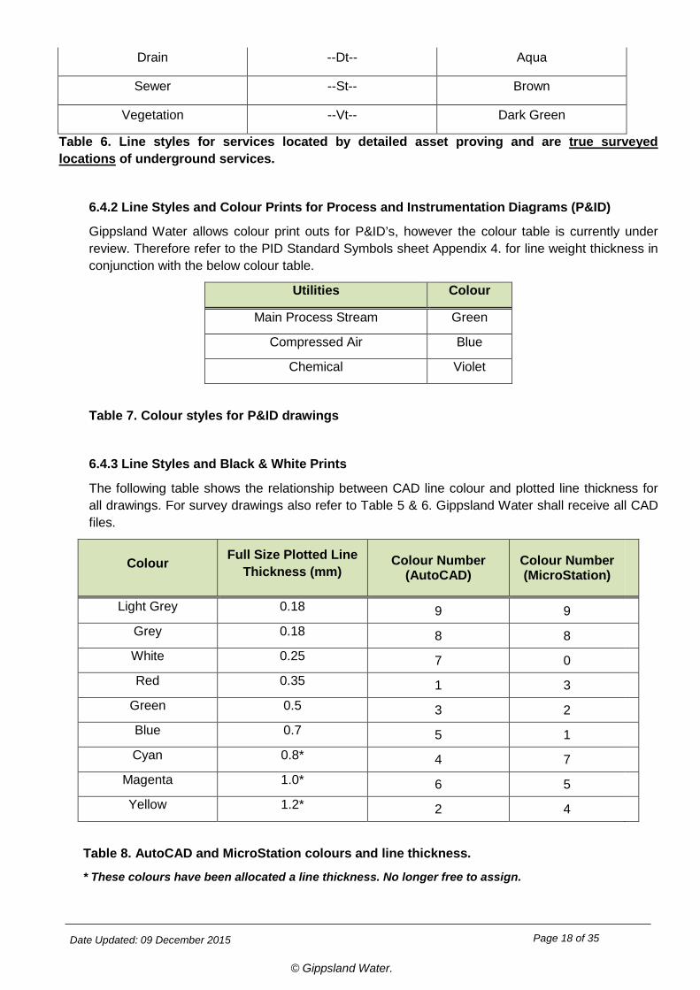
Vegetation --Vt-- Dark Green
Table 6. Line styles for services located by detailed asset proving and are true surveyed locations of underground services.
6.4.2 Line Styles and Colour Prints for Process and Instrumentation Diagrams (P&ID)
Gippsland Water allows colour print outs for P&ID’s, however the colour table is currently under review. Therefore refer to the PID Standard Symbols sheet Appendix 4. for line weight thickness in conjunction with the below colour table.
Utilities Colour
Main Process Stream Green
Compressed Air Blue
Chemical Violet
Table 7. Colour styles for P&ID drawings
6.4.3 Line Styles and Black & White Prints
The following table shows the relationship between CAD line colour and plotted line thickness for all drawings. For survey drawings also refer to Table 5 & 6. Gippsland Water shall receive all CAD files.
Colour Full Size Plotted Line Thickness (mm)
Colour Number (AutoCAD)
Colour Number (MicroStation)
Light Grey 0.18 9 9
Grey 0.18 8 8
White 0.25 7 0
Red 0.35 1 3
Green 0.5 3 2
Blue 0.7 5 1
Cyan 0.8* 4 7
Magenta 1.0* 6 5
Yellow 1.2* 2 4
Table 8. AutoCAD and MicroStation colours and line thickness.
* These colours have been allocated a line thickness. No longer free to assign.
Date Updated: 09 December 2015 Page 19 of 35
© Gippsland Water.
6.5 SPECIAL PURPOSE DRAWINGS
This section is intended to cover drawings which fit into the following categories:
1. Large scale topographic drawings 2. Large scale thematic mapping drawings.
Gippsland Water will allow the use of fonts not complying with Section 6.1 and the use of restricted use drawing borders for drawings which meet all of the following criteria:
1. Drawing does not fit into the standard drafting disciplines: • Civil
• Structural
• Electrical
• Mechanical
• Architectural
• Survey • Charts or graphics
2. Drawing scale is not less than 1:5000
Drawings that meet the requirements of this Section may have no restriction on font style and are eligible to use Gippsland Water’s restricted use drawing borders.
The restricted use drawing borders available are: • A1 portrait • A0 landscape
• A0 portrait
7. SPECIFIC REQUIREMENTS FOR DRAWING DISCIPLINE Depending on the drawing discipline, some drawings require extra information and guidelines on Gippsland Water expectations and requirements. The different drawing disciplines include:
• Civil
• Structural
• Electrical
• Mechanical
• Architectural
• Survey
• Charts or graphics
Refer to Gippsland Water Design Standards.
Date Updated: 09 December 2015 Page 20 of 35
© Gippsland Water.
8. SPECIFIC REQUIREMENTS FOR GIPPSLAND WATER DEPARTMENTS Various departments within Gippsland Water use drawing information for various tasks. In particular Land Development and Commercial services still maintain some drawing information and work in conjunction with the AMIS department. See below detail:
8.1 Land Development
Land development is responsible for providing and receiving information from external consultants and contractors for new estates, sub-divisions and existing assets. They maintain developer works drawing information such as:
• As-Constructed CAD and PDF drawings
• Field notes
• Field survey
• Updates to Gippsland Water GIS
Typical field note format and layout drawings are provided in PDF on the Gippsland Water website to view as examples of the requirements expected. Refer to drawings A4-59288: Field Notes of Water Supply Works and A4-59289: Field Notes of Sewerage Works.
Refer to the Gippsland Water website under:
• Commercial Customers/Tenders/ Drafting Specifications and/or
• Developers-Builders/ Information for Developers/Drafting Specifications
8.2 Commercial Services
Commercial services has a Land & Legal departments that manages:
• Titles
• Land boundaries
Date Updated: 09 December 2015 Page 21 of 35
© Gippsland Water.
9. AMIS DRAWING MANAGEMENT PROCESSES To maintain consistent and accurate drawing records, new and existing drawings must be maintained within Gippsland Water electronic document management system. Gippsland Water’s AMIS department provides drawing information to internal and external stakeholders.
This section identifies how drawings are managed by the AMIS Records Management Officer (RMO). The specific tasks include:
• Issuing drawing numbers and providing facility codes
• Checking out existing drawings for update
• Uploading new and existing drawings into Gippsland Water drawing management system
• Tracking revision number updates
• Superseding and Archiving drawings
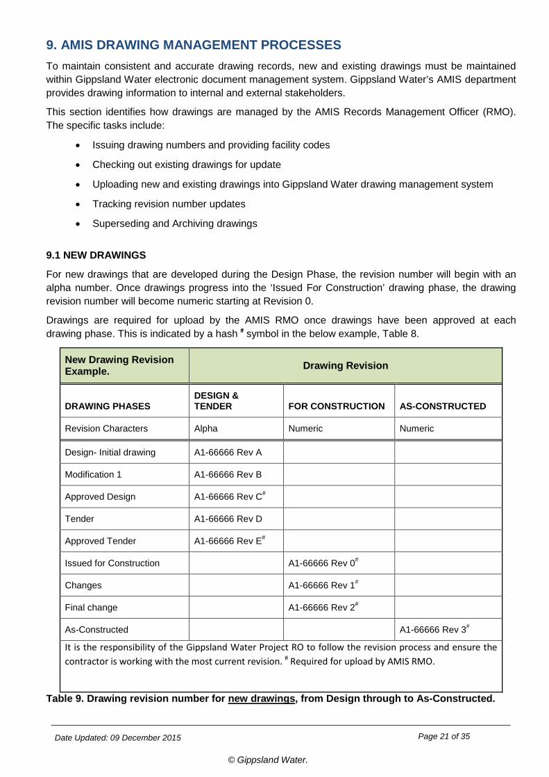
9.1 NEW DRAWINGS
For new drawings that are developed during the Design Phase, the revision number will begin with an alpha number. Once drawings progress into the ‘Issued For Construction’ drawing phase, the drawing revision number will become numeric starting at Revision 0.
Drawings are required for upload by the AMIS RMO once drawings have been approved at each drawing phase. This is indicated by a hash # symbol in the below example, Table 8.
New Drawing Revision Example. Drawing Revision
DRAWING PHASES DESIGN & TENDER FOR CONSTRUCTION AS-CONSTRUCTED
Revision Characters Alpha Numeric Numeric
Design- Initial drawing A1-66666 Rev A
Modification 1 A1-66666 Rev B
Approved Design A1-66666 Rev C#
Tender A1-66666 Rev D
Approved Tender A1-66666 Rev E#
Issued for Construction A1-66666 Rev 0#
Changes A1-66666 Rev 1#
Final change A1-66666 Rev 2#
As-Constructed A1-66666 Rev 3#
It is the responsibility of the Gippsland Water Project RO to follow the revision process and ensure the contractor is working with the most current revision. # Required for upload by AMIS RMO.
Table 9. Drawing revision number for new drawings, from Design through to As-Constructed.
Date Updated: 09 December 2015 Page 22 of 35
© Gippsland Water.
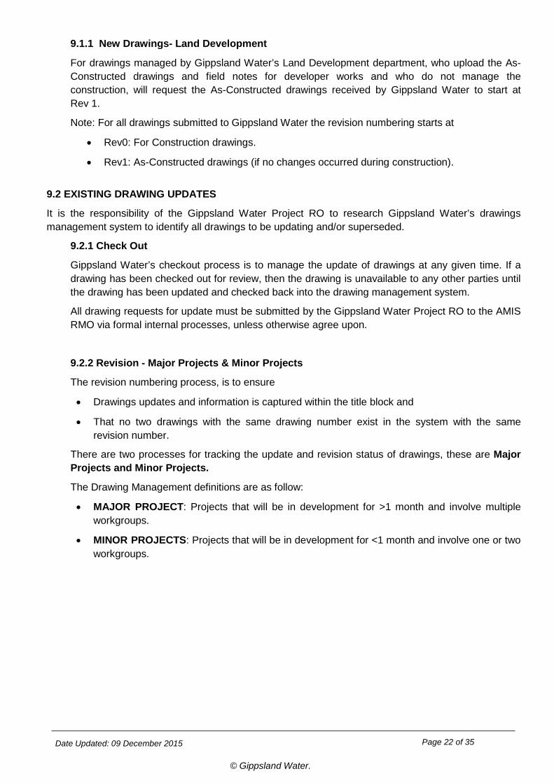
9.1.1 New Drawings- Land Development
For drawings managed by Gippsland Water’s Land Development department, who upload the As-Constructed drawings and field notes for developer works and who do not manage the construction, will request the As-Constructed drawings received by Gippsland Water to start at Rev 1.
Note: For all drawings submitted to Gippsland Water the revision numbering starts at
• Rev0: For Construction drawings.
• Rev1: As-Constructed drawings (if no changes occurred during construction).
9.2 EXISTING DRAWING UPDATES
It is the responsibility of the Gippsland Water Project RO to research Gippsland Water’s drawings management system to identify all drawings to be updating and/or superseded.
9.2.1 Check Out
Gippsland Water’s checkout process is to manage the update of drawings at any given time. If a drawing has been checked out for review, then the drawing is unavailable to any other parties until the drawing has been updated and checked back into the drawing management system.
All drawing requests for update must be submitted by the Gippsland Water Project RO to the AMIS RMO via formal internal processes, unless otherwise agree upon.
9.2.2 Revision - Major Projects & Minor Projects
The revision numbering process, is to ensure
• Drawings updates and information is captured within the title block and
• That no two drawings with the same drawing number exist in the system with the same revision number.
There are two processes for tracking the update and revision status of drawings, these are Major Projects and Minor Projects.
The Drawing Management definitions are as follow:
• MAJOR PROJECT: Projects that will be in development for >1 month and involve multiple workgroups.
• MINOR PROJECTS: Projects that will be in development for <1 month and involve one or two workgroups.
Date Updated: 09 December 2015 Page 23 of 35
© Gippsland Water.
9.2.2.1 Major Projects
To update existing drawings for a major project, Table 10 shows the revision numbering process from original checkout to the As-Constructed drawings.
Existing drawings have a numeric revision number. To update existing drawings, the drawing must be modified to include an alpha revision number in conjunction with the existing revision number.
While existing drawings are in the preliminary design phase, the revision number will include the alpha revision number after the existing drawing number (3A in the below example). Once the drawing becomes real for field installation referred to as ‘Issued for Construction’ the revision number will be revved up to the next numeric revision number until the completion of the project with ‘As-Constructed’ drawing produced.
Existing Drawing Revision Example. Drawing Revision
Drawing Phases DESIGN & TENDER
FOR CONSTRUCTION
AS-CONSTRUCTED
Revision Characters Numeric & Alpha Numeric Numeric
As-Constructed (existing) A1-99999 Rev 3*
New Design- modification A1-99999 Rev 3A
Approved Design A1-99999 Rev 3B#
Tender A1-99999 Rev 3C
Approved Tender A1-99999 Rev 3D#
Issued for Construction A1-99999 Rev 4#
Changes A1-99999 Rev 5#
Final change A1-99999 Rev 6#
Finalised/As Constructed A1-99999 Rev 7#
It is the responsibility of the Gippsland Water Project RO to follow the revision process and ensure the contractor is working with the most current revision. * This drawing must be checked out (Section 9.2.1) # Required for upload by AMIS RMO.
Table 10. Drawing revision number for existing drawings, from Design through to As-Constructed.
Date Updated: 09 December 2015 Page 24 of 35
© Gippsland Water.
9.2.2.2 Minor Projects
To update existing drawings for a minor project, Table 11 shows the revision numbering process from original checkout to As-Constructed drawings.
For a MINOR PROJECT <1 Month, is for basic works that can be tracked via Redline Mark Ups. Through this process, the existing drawing is checked out and redlined marked up. The information is then provided to the drafting consultant, who will make the changes and revise the drawing number. This is common for PID updates.
Existing Drawing Revision Example. Drawing Revision
Drawing Phases DESIGN & TENDER
FOR CONSTRUCTION
AS-CONSTRUCTED
Revision Characters Numeric & Alpha Numeric Numeric
As-Constructed (existing) A1-99999 Rev 3*
Redline Mark-up
GIPPSLAND WATER PO/RO A1-99999 Rev 3A N/A
Finalised/As Constructed
A1-99999 Rev 4#
It is the responsibility of the Gippsland Water Project RO to follow the revision process and ensure the contractor is working with the most current revision. * This drawing must be checked out (Section 9.2.1), # Required for upload by AMIS RMO.
Table 11. Drawing revision number for existing drawings. Redline mark-up from design through to As-Constructed.
9.3 REVISION IDENTIFICATION
During updates to drawings through design and construction, clouding will be used to identify what changes are made to the previous drawing revision and if a section has insufficient information at the time of drawing issue. Revision clouding is not required on the initial drawing.
9.3.1 Revision Clouding for Existing Drawings
Revision updates shall be identified by drawing an outline cloud around the revised area. When subsequent revisions are made, the cloud and any previous identifier relating to the previous revision shall be removed and the new changes clouded.
For existing drawing updates, the clouds will be colour coded to represent the change, as follows:
• Blue cloud: New Item eg, new asset, new process stream.
• Yellow cloud: Update or relocation on the drawing eg, asset coding change, location of an asset.
• Pink cloud: Deleted from the drawing
Date Updated: 09 December 2015 Page 25 of 35
© Gippsland Water.
Therefore the previous revision can be viewed and compared to the updated revision with the clouds. This can be used for field installation works and for asset management.
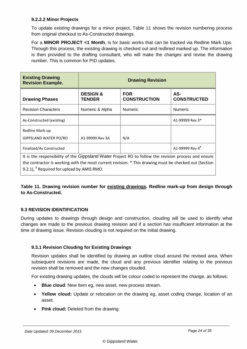
In the revision box, the new revision status shall be shown with a brief, specific note of the change and the revision number updated.
When a drawing is issued as As-Constructed, all clouding shall be removed i.e., the As-Constructed issue shall be in a ‘clean’ state.
9.3.2 Hold
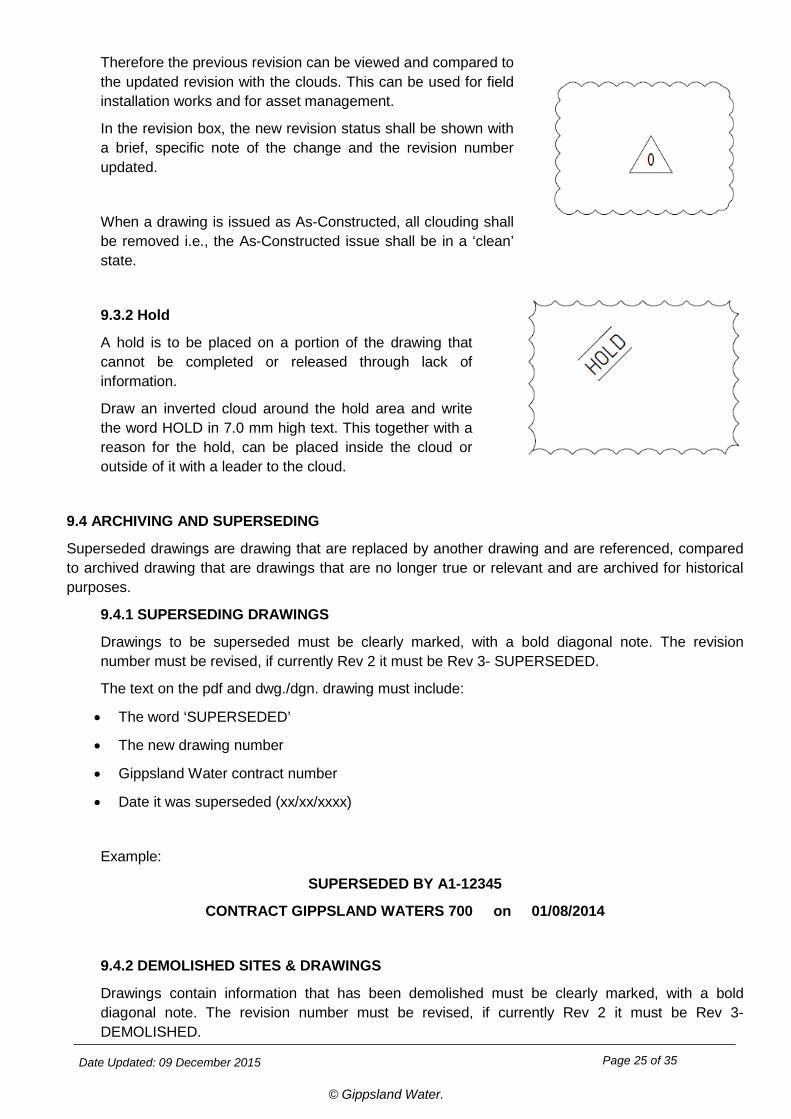
A hold is to be placed on a portion of the drawing that cannot be completed or released through lack of information.
Draw an inverted cloud around the hold area and write the word HOLD in 7.0 mm high text. This together with a reason for the hold, can be placed inside the cloud or outside of it with a leader to the cloud.
9.4 ARCHIVING AND SUPERSEDING
Superseded drawings are drawing that are replaced by another drawing and are referenced, compared to archived drawing that are drawings that are no longer true or relevant and are archived for historical purposes.
9.4.1 SUPERSEDING DRAWINGS
Drawings to be superseded must be clearly marked, with a bold diagonal note. The revision number must be revised, if currently Rev 2 it must be Rev 3- SUPERSEDED.
The text on the pdf and dwg./dgn. drawing must include:
• The word ‘SUPERSEDED’
• The new drawing number
• Gippsland Water contract number
• Date it was superseded (xx/xx/xxxx)
Example:
SUPERSEDED BY A1-12345
CONTRACT GIPPSLAND WATERS 700 on 01/08/2014
9.4.2 DEMOLISHED SITES & DRAWINGS
Drawings contain information that has been demolished must be clearly marked, with a bold diagonal note. The revision number must be revised, if currently Rev 2 it must be Rev 3- DEMOLISHED.
new drawing detail
Date Updated: 09 December 2015 Page 26 of 35
© Gippsland Water.
9.4.3 ARCHIVING DRAWINGS
Gippsland Water will archive drawings via internal processes.
10. DRAWING ETIQUETTE Gippsland Water requires drawing etiquette standards to be complied with when working with multiple drafting consultants and engineering firms.
Gippsland Water drawing etiquette requirements must be followed by all consultants and companies that produce drawings for Gippsland Water. These include and are not limited to:
10.1 CONVERSION OF DRAWING FILE FORMATS
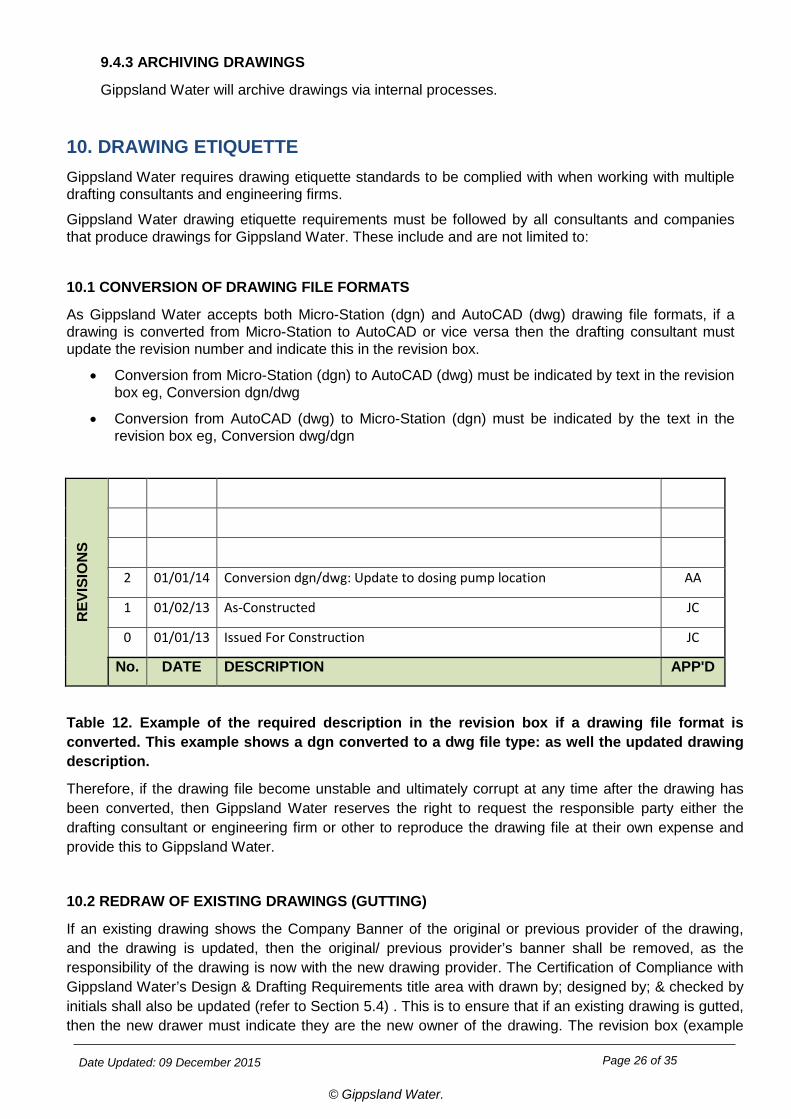
As Gippsland Water accepts both Micro-Station (dgn) and AutoCAD (dwg) drawing file formats, if a drawing is converted from Micro-Station to AutoCAD or vice versa then the drafting consultant must update the revision number and indicate this in the revision box.
• Conversion from Micro-Station (dgn) to AutoCAD (dwg) must be indicated by text in the revision box eg, Conversion dgn/dwg
• Conversion from AutoCAD (dwg) to Micro-Station (dgn) must be indicated by the text in the revision box eg, Conversion dwg/dgn
REV
ISIO
NS
2 01/01/14 Conversion dgn/dwg: Update to dosing pump location AA
1 01/02/13 As-Constructed JC
0 01/01/13 Issued For Construction JC
No. DATE DESCRIPTION APP'D
Table 12. Example of the required description in the revision box if a drawing file format is converted. This example shows a dgn converted to a dwg file type: as well the updated drawing description.
Therefore, if the drawing file become unstable and ultimately corrupt at any time after the drawing has been converted, then Gippsland Water reserves the right to request the responsible party either the drafting consultant or engineering firm or other to reproduce the drawing file at their own expense and provide this to Gippsland Water.
10.2 REDRAW OF EXISTING DRAWINGS (GUTTING)
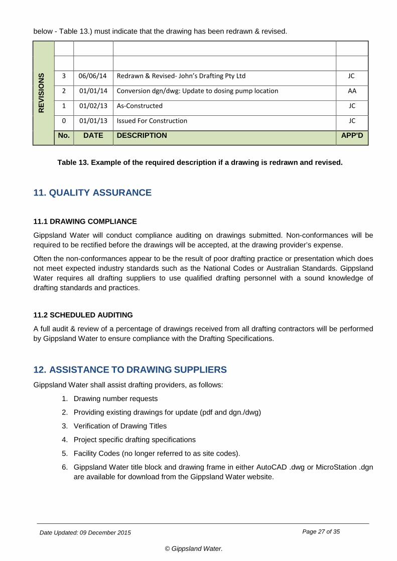
If an existing drawing shows the Company Banner of the original or previous provider of the drawing, and the drawing is updated, then the original/ previous provider’s banner shall be removed, as the responsibility of the drawing is now with the new drawing provider. The Certification of Compliance with Gippsland Water’s Design & Drafting Requirements title area with drawn by; designed by; & checked by initials shall also be updated (refer to Section 5.4) . This is to ensure that if an existing drawing is gutted, then the new drawer must indicate they are the new owner of the drawing. The revision box (example
Date Updated: 09 December 2015 Page 27 of 35
© Gippsland Water.
below - Table 13.) must indicate that the drawing has been redrawn & revised. R
EVIS
ION
S
3 06/06/14 Redrawn & Revised- John’s Drafting Pty Ltd JC
2 01/01/14 Conversion dgn/dwg: Update to dosing pump location AA
1 01/02/13 As-Constructed JC
0 01/01/13 Issued For Construction JC
No. DATE DESCRIPTION APP'D
Table 13. Example of the required description if a drawing is redrawn and revised.
11. QUALITY ASSURANCE
11.1 DRAWING COMPLIANCE
Gippsland Water will conduct compliance auditing on drawings submitted. Non-conformances will be required to be rectified before the drawings will be accepted, at the drawing provider’s expense.
Often the non-conformances appear to be the result of poor drafting practice or presentation which does not meet expected industry standards such as the National Codes or Australian Standards. Gippsland Water requires all drafting suppliers to use qualified drafting personnel with a sound knowledge of drafting standards and practices.
11.2 SCHEDULED AUDITING
A full audit & review of a percentage of drawings received from all drafting contractors will be performed by Gippsland Water to ensure compliance with the Drafting Specifications.
12. ASSISTANCE TO DRAWING SUPPLIERS Gippsland Water shall assist drafting providers, as follows:
1. Drawing number requests
2. Providing existing drawings for update (pdf and dgn./dwg)
3. Verification of Drawing Titles
4. Project specific drafting specifications
5. Facility Codes (no longer referred to as site codes).
6. Gippsland Water title block and drawing frame in either AutoCAD .dwg or MicroStation .dgn are available for download from the Gippsland Water website.
Date Updated: 09 December 2015 Page 28 of 35
© Gippsland Water.
14. FURTHER INFORMATION For the latest copy of this document and other related drafting specifications and standard drawing borders you can either contact the below personal or search the Gippsland Water website at www.gippswater.com.au
Property services and connections matters contact:
Land Development Team Leader: Anthony Faltum (03) 5177 4734
Drawing, drafting and engineering contractual matters contact:
Drafting Contracts Engineer: Rohan Beaton (03) 5177 4615
Drawings management and drafting specifications matters contact:
AMIS Records Management Officer: Brooke Samblebe (03) 5177 4705
Date Updated: 09 December 2015
© Gippsland Water.
Page 29 of 35
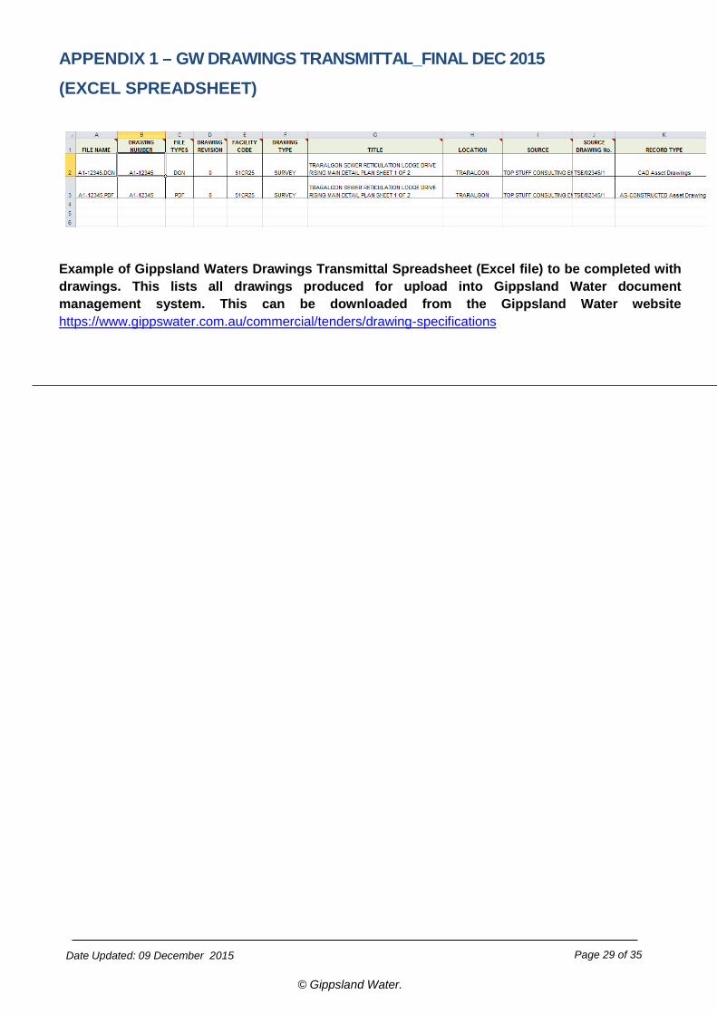
APPENDIX 1 – GW DRAWINGS TRANSMITTAL_FINAL DEC 2015
(EXCEL SPREADSHEET)
Example of Gippsland Waters Drawings Transmittal Spreadsheet (Excel file) to be completed with drawings. This lists all drawings produced for upload into Gippsland Water document management system. This can be downloaded from the Gippsland Water website https://www.gippswater.com.au/commercial/tenders/drawing-specifications
Date Updated: 09 December 2015
© Gippsland Water.
Page 30 of 35
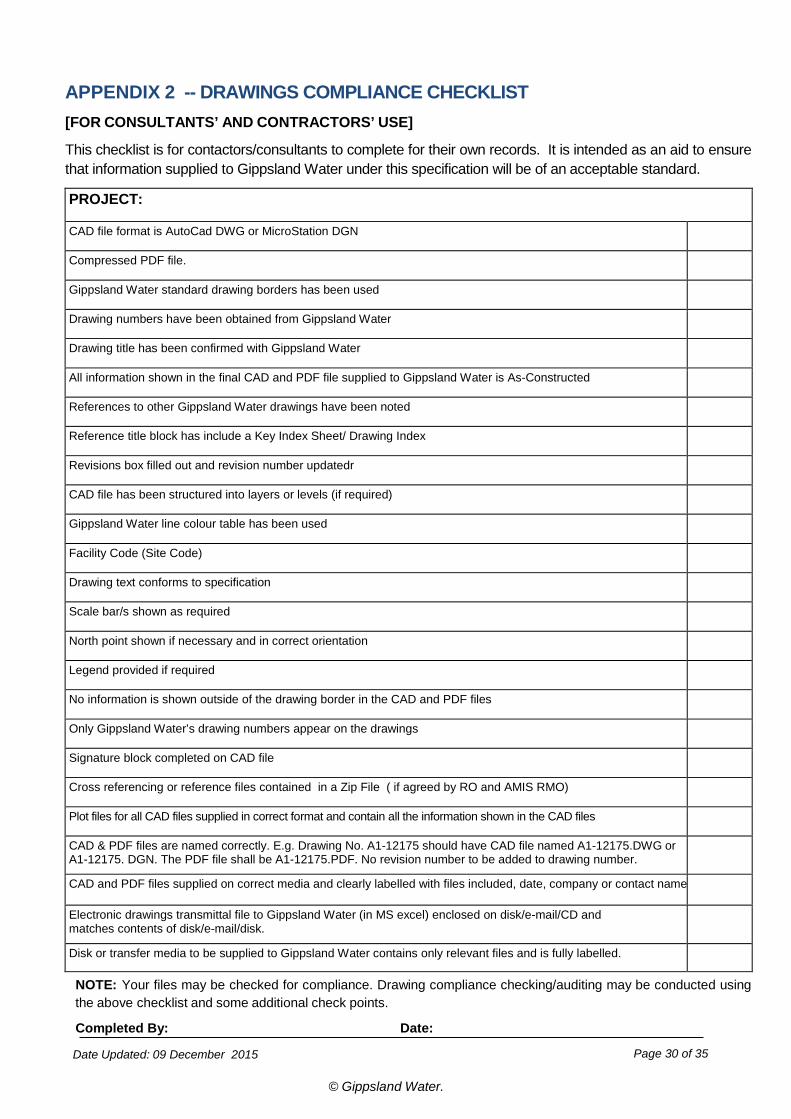
APPENDIX 2 -- DRAWINGS COMPLIANCE CHECKLIST [FOR CONSULTANTS’ AND CONTRACTORS’ USE]
This checklist is for contactors/consultants to complete for their own records. It is intended as an aid to ensure that information supplied to Gippsland Water under this specification will be of an acceptable standard.
PROJECT: CAD file format is AutoCad DWG or MicroStation DGN
Compressed PDF file.
Gippsland Water standard drawing borders has been used
Drawing numbers have been obtained from Gippsland Water
Drawing title has been confirmed with Gippsland Water
All information shown in the final CAD and PDF file supplied to Gippsland Water is As-Constructed
References to other Gippsland Water drawings have been noted
Reference title block has include a Key Index Sheet/ Drawing Index
Revisions box filled out and revision number updatedr
CAD file has been structured into layers or levels (if required)
Gippsland Water line colour table has been used
Facility Code (Site Code)
Drawing text conforms to specification
Scale bar/s shown as required
North point shown if necessary and in correct orientation
Legend provided if required
No information is shown outside of the drawing border in the CAD and PDF files
Only Gippsland Water’s drawing numbers appear on the drawings
Signature block completed on CAD file
Cross referencing or reference files contained in a Zip File ( if agreed by RO and AMIS RMO)
Plot files for all CAD files supplied in correct format and contain all the information shown in the CAD files
CAD & PDF files are named correctly. E.g. Drawing No. A1-12175 should have CAD file named A1-12175.DWG or A1-12175. DGN. The PDF file shall be A1-12175.PDF. No revision number to be added to drawing number.
CAD and PDF files supplied on correct media and clearly labelled with files included, date, company or contact name
Electronic drawings transmittal file to Gippsland Water (in MS excel) enclosed on disk/e-mail/CD and matches contents of disk/e-mail/disk.
Disk or transfer media to be supplied to Gippsland Water contains only relevant files and is fully labelled.
NOTE: Your files may be checked for compliance. Drawing compliance checking/auditing may be conducted using the above checklist and some additional check points.
Completed By: Date:
Date Updated: 09 December 2015
© Gippsland Water.
Page 31 of 35
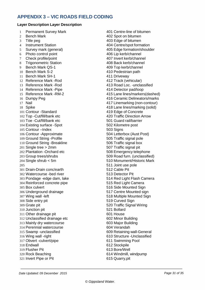
APPENDIX 3 – VIC ROADS FIELD CODING Layer Description Layer Description
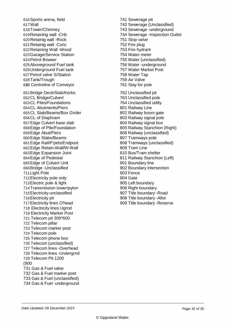
1 Permanent Survey Mark 401 Centre-line of bitumen 2 Bench Mark 402 Spot on bitumen 3 Title peg 403 Edge of bitumen 4 Instrument Station 404 Centre/spot formation 5 Survey mark (general) 405 Edge formation/shoulder 6 Photo control point 406 Lip kerb/channel 7 Check profile/point 407 Invert kerb/channel 8 Trigonometric Station 408 Back kerb/channel 9 Bench Mark QS-1 409 Top kerb/channel 10 Bench Mark S-2 410 Pedestrian path 11 Bench Mark SH-1 411 Driveway 12 Reference Mark -Rod 412 Track (vehicular) 13 Reference Mark -Rod 413 Road Loc. -unclassified 14 Reference Mark -Pipe 414 Detector pad/loop 15 Reference Mark -RM-2 415 Lane lines/markers(dashed) 16 Dumpy Peg 416 Ceramic Delineators/marks 17 Nail 417 Linemarking (non-contour) 18 Spike 418 Lane lines/marking (solid) 101 Contour -Standard 419 Edge of Concrete 102 Top -Cut/fill/bank etc 420 Traffic Direction Arrow 103 Toe -Cut/fill/bank etc 501 Guard rail/barrier 104 Existing surface -Spot 502 Kilometre post 105 Contour –Index 503 Signs 106 Contour -Approximate 504 Letterbox (Aust Post) 109 Ground String -Profile 505 Traffic signal pole 110 Ground String -Breakline 506 Traffic signal box 201 Single tree > 2mm 507 Traffic signal pit 202 Plantation -Orchard etc 508 Emergency telephone 203 Group trees/shrubs 509 Road furn. (unclassified) 204 Single shrub < 5m 510 Monument/Historic Mark 205 511 Joint use pole 301 Drain-Drain conc/earth 512 Cable Pit 302 Watercourse -bed river 513 Detector Pit 303 Pondage -edge dam, lake 514 Red Light Flash Camera 304 Reinforced concrete pipe 515 Red Light Camera 305 Box culvert 516 Side Mounted Sign 306 Underground drainage 517 Centre Mounted sign 307 Wing wall -left 518 Multiple Mounted Sign 308 Side entry pit 519 Curved Sign 309 Grate pit 520 Traffic Signal Wiring 310 Junction pit 521 Bollard 311 Other drainage pit 601 House 312 Unclassified drainage etc 602 Minor Building 313 Mainly dry watercourse 603 Major Building 314 Perennial watercourse 604 Verandah 315 Swamp -unclassified 609 Retaining wall-General 316 Wing wall -right 610 Structure -Unclassified 317 Obvert -culvert/pipe 611 Swimming Pool 318 Endwall 612 Stockpile 319 Flusher Pit 613 Bore/Well 320 Rock Beaching 614 Windmill, windpump 321 Invert Pipe or Pit 615 Quarry,pit
Date Updated: 09 December 2015
© Gippsland Water.
Page 32 of 35
616 Sports arena, field 741 Sewerage pit 617 Wall 742 Sewerage (Unclassified) 618 Tower/Chimney 743 Sewerage -underground 619 Retaining wall -Crib 744 Sewerage -Inspection Outlet 620 Retainig wall -Rock 751 Stop valve 621 Retainig wall -Conc 752 Fire plug 622 Retaining Wall -Wood 753 Fire hydrant 623 Garage/Service Station 754 Water meter 624 Petrol Bowser 755 Water (unclassified) 625 Aboveground Fuel tank 756 Water -underground 626 Underground Fuel tank 757 Water Market Post 627 Petrol valve S/Station 758 Water Tap 628 Tank/Trough 759 Air Valve 638 Centreline of Conveyor 761 Stay for pole
651 Bridge Deck/Slab/Kerbs 762 Unclassified pit 652 CL Bridge/Culvert 763 Unclassified pole 653 CL Piles/Foundations 764 Unclassified utility 654 CL Abutments/Piers 801 Railway Line 655 CL Slab/Beams/Box Girder 802 Railway boom gate 656 CL of Diaphram 803 Railway signal pole 657 Edge Culvert base slab 804 Railway signal box 658 Edge of Pile/Foundation 805 Railway Stanchion (Right) 659 Edge Abut/Piers 806 Railway (unclassified) 660 Edge Slabs/Beams 807 Tramways pole 661 Edge Rail/P'pets/Endpost 808 Tramways (unclassified) 662 Edge Retain-Wall/W-Wall 809 Tram Line 663 Edge Expansion Joint 810 Bus/Tram shelter 664 Edge of Pedestal 811 Railway Stanchion (Left) 665 Edge of Culvert Unit 901 Boundary line 666 Bridge -Unclassified 902 Boundary intersection 711 Light Pole 903 Fence 712 Electricity pole only 904 Gate 713 Electric pole & light 905 Left boundary 714 Transmission tower/pylon 906 Right boundary 715 Electricity-unclassified 907 Title boundary -Road 716 Electricity pit 908 Title boundary -Allot 717 Electricity lines O'head 909 Title boundary -Reserve 718 Electricity lines Ugrnd 719 Electricity Marker Post 721 Telecom pit 300*600 722 Telecom pillar 723 Telecom marker post 724 Telecom pole 725 Telecom phone box 726 Telecom (unclassified) 727 Telecom lines -Overhead 728 Telecom lines -Undergrnd 729 Telecom Pit 1200 (900 731 Gas & Fuel valve 732 Gas & Fuel marker post 733 Gas & Fuel (unclassified) 734 Gas & Fuel -underground
Date Updated: 09 December 2015
© Gippsland Water.
Page 33 of 35
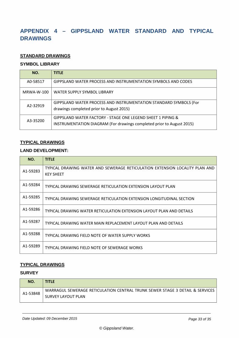
APPENDIX 4 – GIPPSLAND WATER STANDARD AND TYPICAL DRAWINGS
STANDARD DRAWINGS
SYMBOL LIBRARY
NO. TITLE
A0-58517 GIPPSLAND WATER PROCESS AND INSTRUMENTATION SYMBOLS AND CODES
MRWA-W-100 WATER SUPPLY SYMBOL LIBRARY
A2-32919 GIPPSLAND WATER PROCESS AND INSTRUMENTATION STANDARD SYMBOLS (For drawings completed prior to August 2015)
A3-35200 GIPPSLAND WATER FACTORY - STAGE ONE LEGEND SHEET 1 PIPING & INSTRUMENTATION DIAGRAM (For drawings completed prior to August 2015)
TYPICAL DRAWINGS
LAND DEVELOPMENT:
NO. TITLE
A1-59283 TYPICAL DRAWING WATER AND SEWERAGE RETICULATION EXTENSION LOCALITY PLAN AND KEY SHEET
A1-59284 TYPICAL DRAWING SEWERAGE RETICULATION EXTENSION LAYOUT PLAN
A1-59285 TYPICAL DRAWING SEWERAGE RETICULATION EXTENSION LONGITUDINAL SECTION
A1-59286 TYPICAL DRAWING WATER RETICULATION EXTENSION LAYOUT PLAN AND DETAILS
A1-59287 TYPICAL DRAWING WATER MAIN REPLACEMENT LAYOUT PLAN AND DETAILS
A1-59288 TYPICAL DRAWING FIELD NOTE OF WATER SUPPLY WORKS
A1-59289 TYPICAL DRAWING FIELD NOTE OF SEWERAGE WORKS
TYPICAL DRAWINGS
SURVEY
NO. TITLE
A1-53848 WARRAGUL SEWERAGE RETICULATION CENTRAL TRUNK SEWER STAGE 3 DETAIL & SERVICES SURVEY LAYOUT PLAN
Date Updated: 09 December 2015
© Gippsland Water.
Page 34 of 35
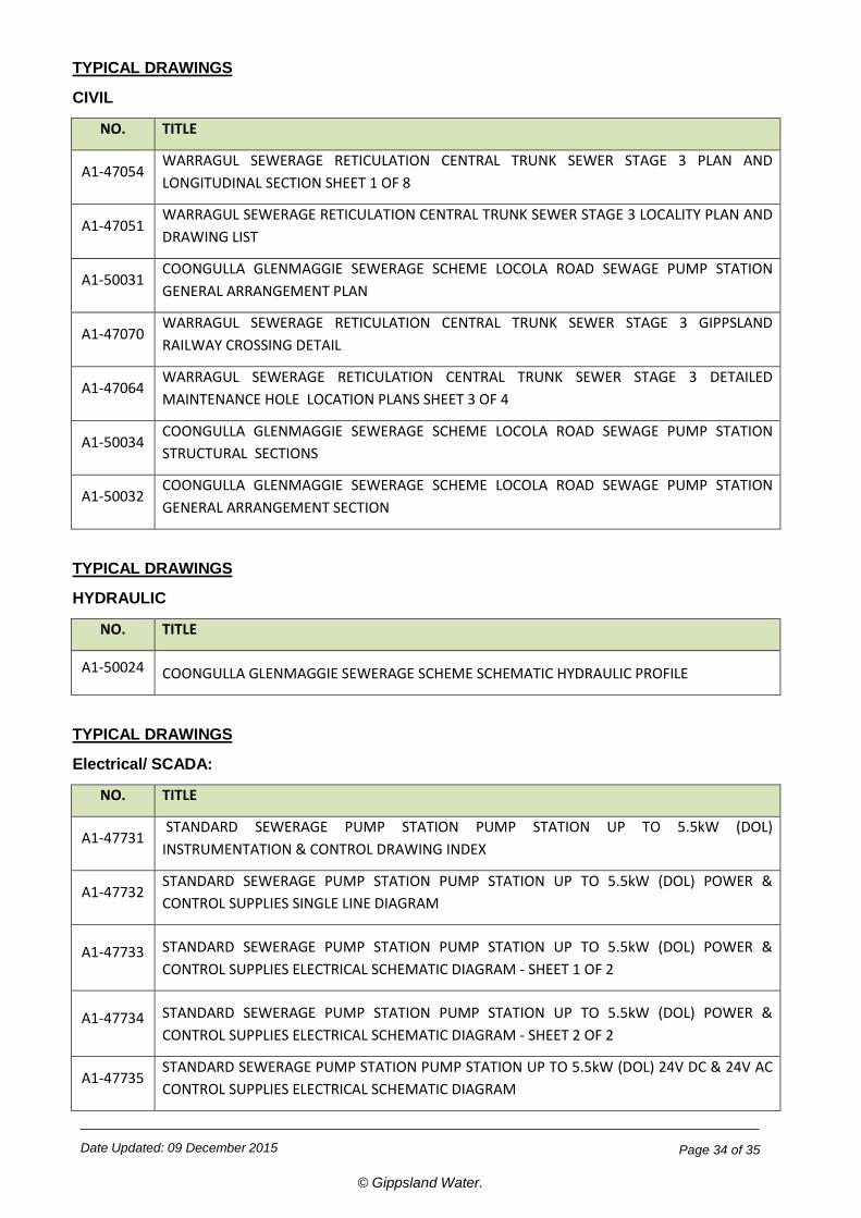
TYPICAL DRAWINGS
CIVIL
NO. TITLE
A1-47054 WARRAGUL SEWERAGE RETICULATION CENTRAL TRUNK SEWER STAGE 3 PLAN AND LONGITUDINAL SECTION SHEET 1 OF 8
A1-47051 WARRAGUL SEWERAGE RETICULATION CENTRAL TRUNK SEWER STAGE 3 LOCALITY PLAN AND DRAWING LIST
A1-50031 COONGULLA GLENMAGGIE SEWERAGE SCHEME LOCOLA ROAD SEWAGE PUMP STATION GENERAL ARRANGEMENT PLAN
A1-47070 WARRAGUL SEWERAGE RETICULATION CENTRAL TRUNK SEWER STAGE 3 GIPPSLAND RAILWAY CROSSING DETAIL
A1-47064 WARRAGUL SEWERAGE RETICULATION CENTRAL TRUNK SEWER STAGE 3 DETAILED MAINTENANCE HOLE LOCATION PLANS SHEET 3 OF 4
A1-50034 COONGULLA GLENMAGGIE SEWERAGE SCHEME LOCOLA ROAD SEWAGE PUMP STATION STRUCTURAL SECTIONS
A1-50032 COONGULLA GLENMAGGIE SEWERAGE SCHEME LOCOLA ROAD SEWAGE PUMP STATION GENERAL ARRANGEMENT SECTION
TYPICAL DRAWINGS
HYDRAULIC
NO. TITLE
A1-50024 COONGULLA GLENMAGGIE SEWERAGE SCHEME SCHEMATIC HYDRAULIC PROFILE
TYPICAL DRAWINGS
Electrical/ SCADA:
NO. TITLE
A1-47731 STANDARD SEWERAGE PUMP STATION PUMP STATION UP TO 5.5kW (DOL) INSTRUMENTATION & CONTROL DRAWING INDEX
A1-47732 STANDARD SEWERAGE PUMP STATION PUMP STATION UP TO 5.5kW (DOL) POWER & CONTROL SUPPLIES SINGLE LINE DIAGRAM
A1-47733 STANDARD SEWERAGE PUMP STATION PUMP STATION UP TO 5.5kW (DOL) POWER & CONTROL SUPPLIES ELECTRICAL SCHEMATIC DIAGRAM - SHEET 1 OF 2
A1-47734 STANDARD SEWERAGE PUMP STATION PUMP STATION UP TO 5.5kW (DOL) POWER & CONTROL SUPPLIES ELECTRICAL SCHEMATIC DIAGRAM - SHEET 2 OF 2
A1-47735 STANDARD SEWERAGE PUMP STATION PUMP STATION UP TO 5.5kW (DOL) 24V DC & 24V AC CONTROL SUPPLIES ELECTRICAL SCHEMATIC DIAGRAM
Date Updated: 09 December 2015
© Gippsland Water.
Page 35 of 35
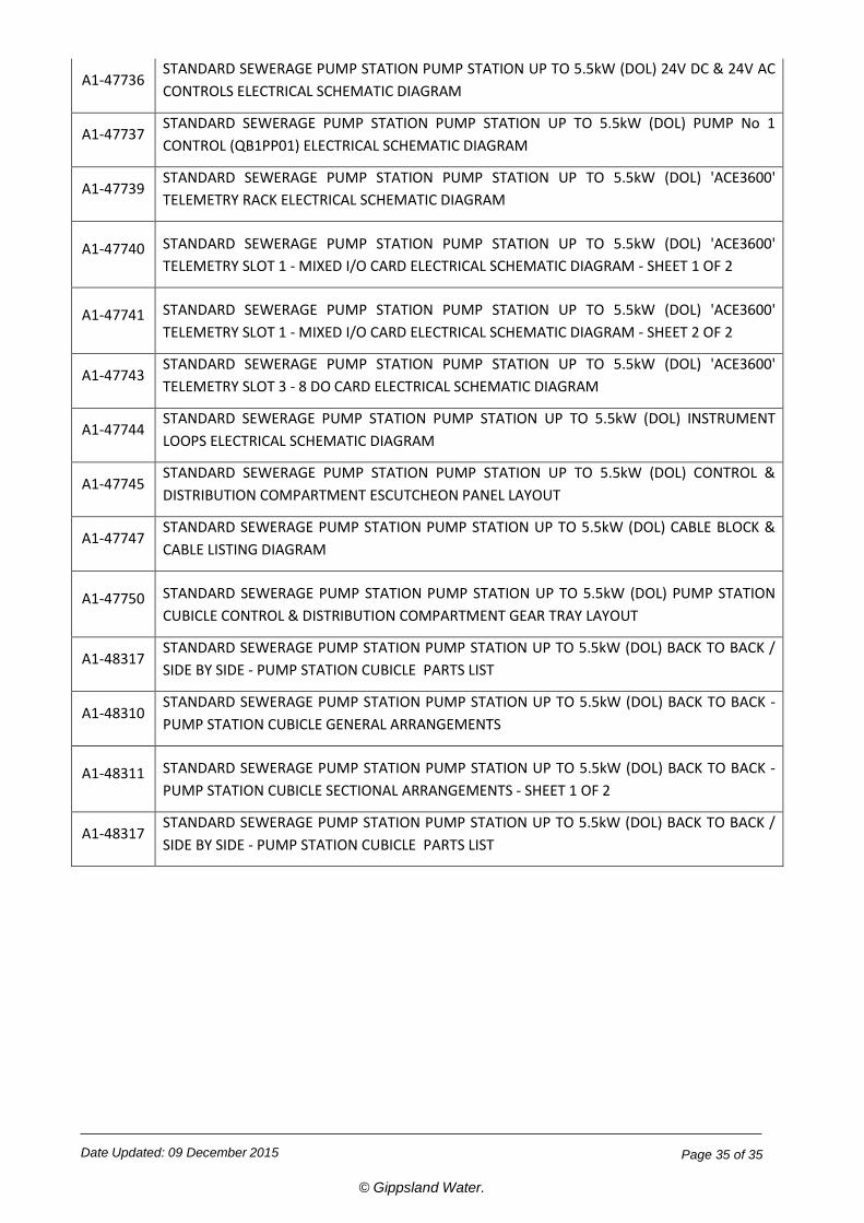
A1-47736 STANDARD SEWERAGE PUMP STATION PUMP STATION UP TO 5.5kW (DOL) 24V DC & 24V AC CONTROLS ELECTRICAL SCHEMATIC DIAGRAM
A1-47737 STANDARD SEWERAGE PUMP STATION PUMP STATION UP TO 5.5kW (DOL) PUMP No 1 CONTROL (QB1PP01) ELECTRICAL SCHEMATIC DIAGRAM
A1-47739 STANDARD SEWERAGE PUMP STATION PUMP STATION UP TO 5.5kW (DOL) 'ACE3600' TELEMETRY RACK ELECTRICAL SCHEMATIC DIAGRAM
A1-47740 STANDARD SEWERAGE PUMP STATION PUMP STATION UP TO 5.5kW (DOL) 'ACE3600' TELEMETRY SLOT 1 - MIXED I/O CARD ELECTRICAL SCHEMATIC DIAGRAM - SHEET 1 OF 2
A1-47741 STANDARD SEWERAGE PUMP STATION PUMP STATION UP TO 5.5kW (DOL) 'ACE3600' TELEMETRY SLOT 1 - MIXED I/O CARD ELECTRICAL SCHEMATIC DIAGRAM - SHEET 2 OF 2
A1-47743 STANDARD SEWERAGE PUMP STATION PUMP STATION UP TO 5.5kW (DOL) 'ACE3600' TELEMETRY SLOT 3 - 8 DO CARD ELECTRICAL SCHEMATIC DIAGRAM
A1-47744 STANDARD SEWERAGE PUMP STATION PUMP STATION UP TO 5.5kW (DOL) INSTRUMENT LOOPS ELECTRICAL SCHEMATIC DIAGRAM
A1-47745 STANDARD SEWERAGE PUMP STATION PUMP STATION UP TO 5.5kW (DOL) CONTROL & DISTRIBUTION COMPARTMENT ESCUTCHEON PANEL LAYOUT
A1-47747 STANDARD SEWERAGE PUMP STATION PUMP STATION UP TO 5.5kW (DOL) CABLE BLOCK & CABLE LISTING DIAGRAM
A1-47750 STANDARD SEWERAGE PUMP STATION PUMP STATION UP TO 5.5kW (DOL) PUMP STATION CUBICLE CONTROL & DISTRIBUTION COMPARTMENT GEAR TRAY LAYOUT
A1-48317 STANDARD SEWERAGE PUMP STATION PUMP STATION UP TO 5.5kW (DOL) BACK TO BACK / SIDE BY SIDE - PUMP STATION CUBICLE PARTS LIST
A1-48310 STANDARD SEWERAGE PUMP STATION PUMP STATION UP TO 5.5kW (DOL) BACK TO BACK - PUMP STATION CUBICLE GENERAL ARRANGEMENTS
A1-48311 STANDARD SEWERAGE PUMP STATION PUMP STATION UP TO 5.5kW (DOL) BACK TO BACK - PUMP STATION CUBICLE SECTIONAL ARRANGEMENTS - SHEET 1 OF 2
A1-48317 STANDARD SEWERAGE PUMP STATION PUMP STATION UP TO 5.5kW (DOL) BACK TO BACK / SIDE BY SIDE - PUMP STATION CUBICLE PARTS LIST