Embed Size (px)
Citation preview

8/3/2019 draft_150_5390_2C
http://slidepdf.com/reader/full/draft15053902c 1/198
Added guidance for load-bearing areas larger than the TLOF, but less than the size of the FATO.
Added guidance for turbulence effects.
AdvisoryU.S. Department
of Transportation
CircularFederal AviationAdministration
Subject: HELIPORT DESIGN Date: DRAFT AC No: 150/5390-2C Initiated by: AAS-100 Change:
1. PURPOSE. This advisory circular (AC) provides recommendations for heliport design, includingheliports serving helicopters with single and tandem (front and rear) rotors. Basic concepts may beapplied to facilities serving helicopters with dual (side by side) rotors, however standards based on RotorDiameter will not apply.
2. CANCELLATION. This AC cancels AC 150/5390-2B, Heliport Design, dated September 30, 2004.
3. APPLICATION. The Federal Aviation Administration (FAA) recommends the guidelines andspecifications in this AC for materials and methods used in the construction of heliports. In general, useof this AC is not mandatory. However, use of this AC is mandatory for all projects funded with Federalgrant monies through the Airport Improvement Program (AIP) and with revenue from the PassengerFacility Charge (PFC). See Grant Assurance No. 34, Policies, Standards, and Specifications, and PFCAssurance No. 9, Standards and Specifications. For information about grant assurances, seehttp://www.faa.gov/airports/aip/grant_assurances/ . The use of terms implying strict compliance appliesonly to those projects. Other Federal Agencies, states, or other authorities having jurisdiction over theconstruction of heliports should decide the extent to which these standards apply.
4. PRINCIPAL CHANGES.
a. Changed the term for the helicopter overall length (OL) to ‘D’ or ‘D-value’.
b. Added definitions for design loads for static and dynamic load-bearing areas (LBA).
c.
d.
e. Added guidance to provide adequate clearance between parking areas and taxi routes and withinparking areas.
f. Added guidance for minimum dimensions of curved approach/departure airspace.
g. Added guidance for Touchdown/Positioning Circle (TDPC) Marking.
h. Added guidance for Flight Path Alignment Guidance markings and lights.
i. Added an appendix providing guidance for Emergency Helicopter Landing Facility Requirements(EHLF).

8/3/2019 draft_150_5390_2C
http://slidepdf.com/reader/full/draft15053902c 2/198
DRAFT AC 150/5390-2C May 19, 2011
j. Added FATO to FATO separation distance for simultaneous operations.
k. Revised standards for size of “H” for GA heliports.
l. Added Heliport Protection Zone to standards for hospital heliports.
m. Combined Chapter 6, Non-Precision Instrument Operations and Chapter 7, Precision ApproachOperations into Chapter 6, Instrument Operations. Reference FAA Order 8620 series.
n. To improve the legibility of the AC, changed the format to a single column and nested the tablesin the text.
5. USE OF METRICS. This AC includes both English and metric dimensions. The metric conversionsmay not be exact equivalents, and the English dimensions govern.
6. COPIES OF THIS AC. This and other advisory circulars published by the Office of Airport Safetyand Standards are available on the Federal Aviation Administration (FAA) Office of Airports web page atwww.faa.gov/airports.
MICHAEL J. O’DONNELLDirector of Airport Safety and Standards
ii

8/3/2019 draft_150_5390_2C
http://slidepdf.com/reader/full/draft15053902c 3/198
May 19, 2011 DRAFT AC 150/5390-2C
TABLE OF CONTENTS Paragraph Page
CHAPTER 1. INTRODUCTION.............................................................................................................. 1101. GENERAL. ............................................................................................................................... 1102. FACILITIES..............................................................................................................................1103. PLANNING. ............................................................................................................................. 1104. LOCATION. ............................................................................................................................. 1105. AC ORGANIZATION.............................................................................................................. 1106. EXPLANATION OF TERMS. ................................................................................................. 2107. SELECTION OF APPROACH/DEPARTURE PATHS........................................................... 5108. NOTIFICATION REQUIREMENTS....................................................................................... 6109. HAZARDS TO AIR NAVIGATION........................................................................................ 9110. FEDERAL ASSISTANCE...................................................................................................... 11111. ENVIRONMENTAL IMPACT ANALYSES. ....................................................................... 12112. ACCESS TO HELIPORTS BY INDIVIDUALS WITH DISABILITIES.............................. 12113. STATE ROLE. ........................................................................................................................ 12114. LOCAL ROLE. ....................................................................................................................... 14115. RELATED/REFERENCED MATERIAL. ............................................................................. 14
CHAPTER 2. GENERAL AVIATION HELIPORTS........................................................................... 15201. GENERAL. ............................................................................................................................. 15202. PRIOR PERMISSION REQUIRED (PPR) FACILITIES ...................................................... 16203. ACCESS BY INDIVIDUALS WITH DISABILITIES........................................................... 16204. HELIPORT SITE SELECTION ............................................................................................. 16205. BASIC LAYOUT.................................................................................................................... 16 206. TOUCHDOWN AND LIFTOFF AREA (TLOF)................................................................... 17207. FINAL APPROACH AND TAKEOFF AREA (FATO). ....................................................... 22208. SAFETY AREA...................................................................................................................... 24209. VFR APPROACH/DEPARTURE PATHS............................................................................. 24210. HELIPORT PROTECTION ZONE (HPZ) ............................................................................. 31211. WIND CONE .......................................................................................................................... 31212. TAXIWAYS AND TAXI ROUTES....................................................................................... 31213. HELICOPTER PARKING...................................................................................................... 37214. HELIPORT MARKERS AND MARKINGS ......................................................................... 46215. HELIPORT LIGHTING.......................................................................................................... 54216. MARKING AND LIGHTING OF DIFFICULT-TO-SEE OBJECTS.................................... 60217. SAFETY CONSIDERATIONS. ............................................................................................. 62218. VISUAL GLIDESLOPE INDICATORS (VGSI). .................................................................. 65219. TERMINAL FACILITIES. ..................................................................................................... 65220. ZONING AND COMPATIBLE LAND USE......................................................................... 65
CHAPTER 3. TRANSPORT HELIPORTS ........................................................................................... 67301. GENERAL .............................................................................................................................. 67302. ACCESS BY INDIVIDUALS WITH DISABILITIES........................................................... 67303. HELIPORT SITE SELECTION. ............................................................................................ 67304. BASIC LAYOUT.................................................................................................................... 69 305. TOUCHDOWN AND LIFTOFF AREA (TLOF). .................................................................. 69
iii

8/3/2019 draft_150_5390_2C
http://slidepdf.com/reader/full/draft15053902c 4/198
DRAFT AC 150/5390-2C May 19, 2011
306. FINAL APPROACH AND TAKEOFF AREA (FATO) ........................................................ 73307. SAFETY AREA...................................................................................................................... 75308. VFR APPROACH/DEPARTURE PATHS............................................................................. 75309. HELIPORT PROTECTION ZONE (HPZ). ............................................................................ 78310. WIND CONE. ......................................................................................................................... 78311. TAXIWAYS AND TAXI ROUTES....................................................................................... 79312. HELICOPTER PARKING...................................................................................................... 79313. HELIPORT MARKERS AND MARKINGS ......................................................................... 91314. HELIPORT LIGHTING.......................................................................................................... 96315. MARKING AND LIGHTING OF DIFFICULT-TO-SEE OBJECTS.................................. 103316. SAFETY CONSIDERATIONS ............................................................................................ 105317. VISUAL GLIDESLOPE INDICATORS (VGSI) ................................................................. 107318. TERMINAL FACILITIES. ................................................................................................... 109319. ZONING AND COMPATIBLE LAND USE....................................................................... 109
CHAPTER 4. HOSPITAL HELIPORTS ............................................................................................. 111401. GENERAL ............................................................................................................................ 111402. ACCESS BY INDIVIDUALS WITH DISABILITIES......................................................... 111403. HELIPORT SITE SELECTION ........................................................................................... 111404. BASIC LAYOUT.................................................................................................................. 113405. TOUCHDOWN AND LIFTOFF AREA (TLOF)................................................................. 114406. FINAL APPROACH AND TAKEOFF AREA (FATO) ...................................................... 116407. SAFETY AREA.................................................................................................................... 118408. VFR APPROACH/DEPARTURE PATHS........................................................................... 120409. HELIPORT PROTECTION ZONE (HPZ) ........................................................................... 126410. WIND CONE ........................................................................................................................ 126411. TAXIWAYS AND TAXI ROUTES..................................................................................... 129412. HELICOPTER PARKING.................................................................................................... 133413. HELIPORT MARKERS AND MARKINGS ....................................................................... 141414. HELIPORT LIGHTING........................................................................................................ 152415. MARKING AND LIGHTING OF DIFFICULT-TO-SEE OBJECTS.................................. 158416. SAFETY CONSIDERATIONS ............................................................................................ 159417. ZONING AND COMPATIBLE LAND USE....................................................................... 162418. VISUAL GLIDESLOPE INDICATORS (VGSI). ................................................................ 162
CHAPTER 5. HELICOPTER FACILITIES ON AIRPORTS........................................................... 165501. GENERAL. ........................................................................................................................... 165502. TOUCHDOWN AND LIFTOFF AREA (TLOF). ................................................................ 165503. FINAL APPROACH AND TAKEOFF AREA (FATO). ..................................................... 165504. SAFETY AREA.................................................................................................................... 165505. VFR APPROACH/DEPARTURE PATHS........................................................................... 165506. HELIPORT PROTECTION ZONE (HPZ). .......................................................................... 165507. TAXIWAYS AND TAXI ROUTES..................................................................................... 166508. HELICOPTER PARKING.................................................................................................... 166509. SECURITY. .......................................................................................................................... 166
CHAPTER 6. INSTRUMENT OPERATIONS.................................................................................... 169601. GENERAL. ........................................................................................................................... 169602. PLANNING .......................................................................................................................... 169603. AIRSPACE............................................................................................................................169604. FINAL APPROACH REFERENCE AREA (FARA). .......................................................... 169
iv

8/3/2019 draft_150_5390_2C
http://slidepdf.com/reader/full/draft15053902c 5/198
May 19, 2011 DRAFT AC 150/5390-2C
605. IMPROVED LIGHTING SYSTEM. .................................................................................... 169606. OBSTACLE EVALUATION SURFACES. ......................................................................... 170
CHAPTER 7. HELIPORT GRADIENTS AND PAVEMENT DESIGN........................................... 173701. GENERAL. ........................................................................................................................... 173702. TLOF GRADIENTS. ............................................................................................................ 173703. FATO GRADIENTS............................................................................................................. 173704. SAFETY AREA GRADIENTS. ........................................................................................... 173705. PARKING AREA GRADIENTS.......................................................................................... 173706. TAXIWAY AND TAXI ROUTE GRADIENTS.................................................................. 173707. DESIGN LOADS.................................................................................................................. 174708. PAVEMENT DESIGN AND SOIL STABILIZATION....................................................... 175
APPENDIX A. EMERGENCY HELICOPTER LANDING FACILITIES (EHLF)........................ 177APPENDIX B. HELICOPTER DATA ................................................................................................. 181APPENDIX C. DIMENSIONS FOR MARKING SIZE AND WEIGHT LIMITATIONS .............187APPENDIX D. ASSOCIATED PUBLICATIONS AND RESOURCES............................................ 189
LIST OF FIGURES
Figure 1–1. Form 7480-1, Notice of Landing Area Proposal ....................................................................... 7Figure 1–2. Example of a Heliport Layout Diagram ....................................................................................8Figure 1–3. Example of a Heliport Location Map ...................................................................................... 11Figure 1–4. Offsite Development Requiring Notice to the FAA................................................................ 13Figure 2-1. Essential Features of a GA Heliport: General Aviation ........................................................... 15Figure 2-2. TLOF/FATO Safety Area Relationships and Minimum Dimensions: General Aviation ........ 18
Figure 2-3. An Elongated FATO with Two Takeoff Positions: General Aviation.....................................20Figure 2-4. Elevated Heliport: General Aviation........................................................................................21Figure 2-5. Additional FATO Length for Heliports at Higher Elevations: General Aviation .................... 23Figure 2-6. Non-load-bearing FATO and Safety Area: General Aviation..................................................25Figure 2-7. VFR Heliport Approach/Departure and Transitional Surfaces: General Aviation................... 27Figure 2-8. Curved Approach/Departure: General Aviation.......................................................................28Figure 2-9. VFR PPR Heliport Lateral Extension of the 8:1 Approach/Departure Surface: General
Aviation................................................................................................................................................29 Figure 2-10. VFR PPR Heliport Lateral Extension of the Curved 8:1 Approach/Departure Surface:
General Aviation ..................................................................................................................................30Figure 2-11. Flight Path Alignment Marking and Lights: General Aviation..............................................32Figure 2-12. Heliport Protection Zone: General Aviation .......................................................................... 33
Figure 2-13. Taxiway/Taxi Route Relationship – Paved Taxiway: General Aviation ............................... 34Figure 2-14. Taxiway/Taxi Route Relationship – Unpaved Taxiway with Raised Edge Markers: General
Aviation................................................................................................................................................35 Figure 2-15. Taxiway/Taxi Route Relationship – Unpaved Taxiway with Flush Edge Markers: General
Aviation................................................................................................................................................36 Figure 2-16. Parking Area Design – “Taxi-through” Parking Positions: General Aviation ....................... 39Figure 2-17. Parking Area Design – “Turn-around” Parking Positions: General Aviation........................40 Figure 2-18. Parking Area Design – “Back-out” Parking Positions: General Aviation..............................41
v

8/3/2019 draft_150_5390_2C
http://slidepdf.com/reader/full/draft15053902c 6/198
DRAFT AC 150/5390-2C May 19, 2011
Figure 2-19. “Turn-around” Parking Position Marking: General Aviation ................................................ 42Figure 2-20. “Taxi-through” and “Back-out” Parking Position Marking: General Aviation ..................... 43Figure 2-21. Parking Position Identification, Size, and Weight Limitations: General Aviation ................ 45Figure 2-22. Standard Heliport Identification Symbol, TLOF Size and Weight Limitations: General
Aviation................................................................................................................................................48 Figure 2-23. LBA Marking: General Aviation ...........................................................................................49Figure 2-24. Paved TLOF/Paved FATO – Paved TLOF/ Unpaved FATO – Marking: General Aviation.50Figure 2-25. Unpaved TLOF/Unpaved FATO – Marking: General Aviation ............................................ 51Figure 2-26. Marking a Closed Heliport: General Aviation ....................................................................... 54Figure 2-27. Elevated TLOF/LBA – Perimeter Lighting: General Aviation..............................................55Figure 2-28. TLOF/FATO Flush Perimeter Lighting: General Aviation....................................................57Figure 2-29. TLOF Flush and FATO Raised Perimeter Lighting: General Aviation ................................. 58Figure 2-30. Landing Direction Lights: General Aviation..........................................................................59Figure 2-31. Airspace Where Marking and Lighting are Recommended: General Aviation ..................... 61Figure 2-32. Caution Sign: General Aviation ............................................................................................. 63Figure 2-33. Visual Glideslope Indicator Siting and Clearance Criteria: General Aviation.......................64Figure 3-1. A Typical Transport Heliport: Transport ................................................................................. 68Figure 3-2. TLOF/FATO Safety Area Relationships and Minimum Dimensions Transport ..................... 70Figure 3-3. An Elongated FATO with Two Takeoff Positions: Transport ................................................. 71Figure 3-4. Elevated Heliport: Transport....................................................................................................72Figure 3-5. Additional FATO Length for Heliports at Higher Elevations: Transport ................................ 73Figure 3-6. Non-load-bearing Safety Area: Transport................................................................................76Figure 3-7. VFR Heliport Approach/Departure and Transitional Surfaces: Transport...............................77Figure 3-8. Curved Approach/Departure: Transport...................................................................................80Figure 3-9. Flight Path Alignment Marking and Lights: Transport............................................................81Figure 3-10. Heliport Protection Zone: Transport ......................................................................................82Figure 3-11. Taxiway/Taxi Route Relationship, Centerline and Edge Marking: Transport.......................83Figure 3-12. “Turn-around” Helicopter Parking Position Marking: Transport ..........................................85Figure 3-13. “Taxi-through” Helicopter Parking Position Marking: Transport..........................................86Figure 3-14. Parking Area Design – “Turn-around” Parking Positions: Transport .................................... 88Figure 3-15. Parking Area Design – “Taxi-through” Parking Position ......................................................89Figure 3-16. Parking Position Identification, Size and Weight Limitations: Transport.............................. 90Figure 3-17. Standard Heliport Identification Symbol, TLOF Size and Weight Limitations: Transport ... 92Figure 3-18. Paved TLOF/Paved FATO – Paved TLOF/Unpaved FATO – Marking: Transport..............93Figure 3-19. Marking a Closed Heliport: Transport ................................................................................... 96Figure 3-20. TLOF and FATO Flush Perimeter Lighting: Transport.........................................................97Figure 3-21. FATO Raised and TLOF Flush Perimeter Lighting: Transport ............................................. 98Figure 3-22. Optional TLOF Lights: Transport ........................................................................................ 100Figure 3-23. Elevated FATO – Perimeter Lighting: Transport.................................................................101Figure 3-24. Landing Direction Lights: Transport....................................................................................102Figure 3-25. Airspace Where Marking and Lighting are Recommended: Transport ...............................104Figure 3-26. Caution Sign: Transport ....................................................................................................... 106Figure 3-27. Visual Glideslope Indicator Siting and Clearance Criteria: Transport.................................108 Figure 4-1. Essential Features of a Ground-level Hospital Heliport: Hospital ......................................... 112Figure 4-2. TLOF/FATO Safety Area Relationships and Minimum Dimension: Hospital......................113Figure 4-3. An Elongated FATO with Two Takeoff Positions: Hospital ................................................. 115Figure 4-4. Additional FATO Length for Heliports at Higher Elevation: Hospital..................................117Figure 4-5. A Rooftop Hospital Heliport: Hospital ..................................................................................120Figure 4-6. VFR Heliport Approach/Departure and Transitional Surfaces: Hospital...............................122Figure 4-7. Curved Approach/Departure: Hospital...................................................................................123Figure 4-8. VFR Heliport Lateral Extension of the 8:1 Approach/Departure Surface: Hospital.............. 124
vi
8/3/2019 draft_150_5390_2C
http://slidepdf.com/reader/full/draft15053902c 7/198
May 19, 2011 DRAFT AC 150/5390-2C
Figure 4-9. VFR Heliport Lateral Extension of the Curved 8:1 Approach/Departure Surface: Hospital . 125Figure 4-10. Flight Path Alignment Marking and Lights: Hospital..........................................................127Figure 4-11. Heliport Protection Zone: Hospital
Figure 4-13. Taxiway/Taxi Route Relationship – Unpaved Taxiway with Raised Edge Markers: Hospital...................................................................................... 128
Figure 4-12. Taxiway/Taxi Route Relationship – Paved Taxiway: Hospital ...........................................130............................................................................................................................................................131
Figure 4-14. Taxiway/Route Relationship – Unpaved Taxiway with Flush Edge Markers: Hospital..... 132Figure 4-15. Parking Area Design – “Taxi-through” Parking Positions: Hospital ................................... 135Figure 4-16. Parking Area Design – “Turn-around” Parking Positions: Hospital .................................... 136Figure 4-17. Parking Area Design – “Back-out” Parking Positions: Hospital..........................................137 Figure 4-18. “Turn-around” Helicopter Parking Position Marking: Hospital ..........................................138Figure 4-19. “Taxi-through” and “Back-out” Helicopter Parking Position Marking: Hospital................ 139Figure 4-20. Parking Position Identification, Size, and Weight Limitations: General Aviation .............. 140Figure 4-21. Standard Hospital Heliport Identification Symbols: Hospital..............................................143Figure 4-22. Alternative Hospital Heliport Identification Symbols: Hospital .......................................... 144Figure 4-23. Paved TLOF/Paved FATO – Paved TLOF/Unpaved FATO – Marking: Hospital..............145Figure 4-24. Unpaved TLOF/Unpaved FATO – Marking: Hospital ........................................................ 146Figure 4-25. TLOF Size and Weight Limitations: Hospital .....................................................................148Figure 4-26. LBA Marking: Hospital .......................................................................................................149Figure 4-27. Marking a Closed Heliport: Hospital ...................................................................................151Figure 4-28. Flush TLOF/FATO Perimeter Lighting: Hospital................................................................153Figure 4-29. Elevated TLOF, Safety Net and Lighting Heliport Partial Elevation: Hospital................... 154Figure 4-30. Flush TLOF and Raised FATO Perimeter Lighting: Hospital ............................................. 155Figure 4-31. Landing Direction Lights: Hospital......................................................................................157Figure 4-32. Airspace Where Marking and Lighting are Recommended: Hospital .................................159Figure 4-33. Caution Sign: Hospital ......................................................................................................... 161Figure 4-34. Visual Glideslope Indicator Siting and Clearance Criteria: Hospital...................................163 Figure 5-1. A Heliport Located on an Airport: On Airport...................................................................... 167Figure 6–1. FARA/FATO Relationship: Precision...................................................................................170Figure 6–2. Heliport Instrument Lighting System (HILS): Nonprecision................................................171Figure 6–3. Heliport Approach Lighting System......................................................................................172Figure 7-1. Heliport Grades and Rapid Runoff Shoulder: Gradients and Pavement ............................... 174Figure 7-2. Helicopter Landing Gear Loading: Gradients and Pavement................................................ 176Figure A-1. Rooftop Emergency Landing Facility ................................................................................... 179Figure B–1. Helicopter Dimensions..........................................................................................................186Figure C–1. Form and Proportions of 3 foot (0.9 m) Numbers for Marking Size and Weight Limitations
............................................................................................................................................................187 Figure C–2. Form and Proportions of 5 foot (1.5 m) Numbers for Marking Size and Weight Limitation
............................................................................................................................................................188 LIST OF TABLES
Table 2-1. Minimum VFR Safety Area Width as a Function of General Aviation and PPR HeliportMarkings...............................................................................................................................................17
Table 2-2. Taxiway / Taxi Route Dimensions – General Aviation Heliports............................................. 38Table 3-1. Taxiway and Taxi Route Dimensions – Transport Heliports .................................................... 84Table 4-1. Minimum VFR Safety Area Width as a Function of Hospital Heliport Markings..................119 Table 4-2. Taxiway / Taxi Route Dimensions – Hospital Heliports.........................................................133Table 5-1. Recommended Distance Between FATO Center to Runway Centerline for VFR Operations165Table B-1. Legend for Table B-2..............................................................................................................181Table B-2. Helicopter Data ....................................................................................................................... 182
vii

8/3/2019 draft_150_5390_2C
http://slidepdf.com/reader/full/draft15053902c 8/198
DRAFT AC 150/5390-2C May 19, 2011
Intentionally left blank
viii
8/3/2019 draft_150_5390_2C
http://slidepdf.com/reader/full/draft15053902c 9/198
May 19, 2011 DRAFT AC 150/5390-2C
CHAPTER 1. INTRODUCTION 101. GENERAL. This chapter provides an explanation of terms used in this AC, describes thenotification responsibilities of heliport proponents to FAA, provides general siting guidance, andidentifies sources of technical information relating to heliport planning and design of a civil heliport.
102. FACILITIES. While heliports can be large and elaborate, most are not. The basic elements of aheliport are clear approach/departure paths, a clear area for ground maneuvers, final approach and takeoff area (FATO), touchdown and liftoff area (TLOF), safety area, and a wind cone. This minimal facility maybe adequate as a private use prior permission required (PPR) heliport, and may even suffice as the initialphase in the development of a public use heliport capable of serving the general aviation segment of thehelicopter community.
103. PLANNING. While the heliport itself may be simple, the planning and organization required toproperly put one into place can be intimidating. This document describes physical, technical, and publicinterest matters that should be considered in the planning and establishment of a heliport. While this ACis a technical document intended to help engineers, architects, and city planners design, locate, and build
the most effective heliport, it can be used by anyone considering the construction of a heliport.
104. LOCATION. The optimum location for a heliport is near the desired origination and/ordestination of the potential users. Industrial, commercial, and business operations in urban locations aredemand generators for helicopter services, even though they often compete for the limited ground spaceavailable. Heliport sites may be adjacent to a river or a lake, a railroad, a freeway, or a highway, all of which offer the potential for multi-functional land usage. These locations also have the advantage of relatively unobstructed airspace, which can be further protected from unwanted encroachment by properlyenacted zoning. As vertical flight transportation becomes more prevalent, requirements for scheduled“airline type” passenger services may necessitate the development of an instrument procedure to permit“all-weather” service.
105. AC ORGANIZATION. This AC is structured to provide communities and persons intending todevelop a heliport, or become involved in regulating helicopter facilities, with general guidance onheliport requirements. The AC covers general aviation heliports (including PPR), transport heliports,hospital heliports, and emergency facilities. A heliport proponent should be familiar with the terminologyused in this specialized field. This chapter defines terms used in the industry and identifies actionscommon to developing a heliport.
a. General aviation heliports: The term “general aviation” is technically defined as “flightsconducted by operators other than title 14 of the Code of Federal Regulations part 121 or part 135certificate holders.” However, for the purposes of this AC, “general aviation” refers to all helicopteroperations other than scheduled passenger service. General aviation heliports are normally privatelyowned although they can be publicly owned. Design standards for general aviation heliports are found in
Chapter 2 on page 15.
b. Transport heliports. Transport heliports are developed to provide the community with a fullrange of vertical flight services including scheduled service by air carriers (airlines) using helicopters.These operations frequently require a more extensive airside and landside infrastructure with the potentialcapability to operate in instrument meteorological conditions. Design standards for transport heliports arefound in Chapter 3 on page 67.
1

8/3/2019 draft_150_5390_2C
http://slidepdf.com/reader/full/draft15053902c 10/198
DRAFT AC 150/5390-2C May 19, 2011
c. Hospital heliports. Hospital heliports provide a unique public service. They are normallylocated close to the hospital emergency room or a medical facility. Design standards for hospital heliportsare found in Chapter 4 on page 111.
d. Helicopter facilities on airports. When there are a significant number of helicopteroperations on an airport, it may be prudent to consider developing separate facilities specifically for
helicopter use. Chapter 5 on page 165 addresses helicopter facilities on airports.
e. Instrument operations. With the introduction of the global positioning system (GPS), it isnow practical for heliports to have instrument approach procedures. Good planning suggests that heliportproponents should plan for the eventual development of instrument approaches to their heliports. Chapter6 on page 169 contains recommendations to be considered in contemplating future instrument operationsat a heliport. It is wise to consider these issues during site selection and design.
f. Heliport gradients and pavement design. Chapter 7 on page 173 addresses heliportgradients and pavement design issues.
g. The appendices provide information about emergency helicopter landing facilities, helicopter
dimensional data, form and proportions of certain heliport markings, and a list of publications andresources referenced in this AC.
106. EXPLANATION OF TERMS. The Pilot/Controller Glossary of the Aeronautical InformationManual (AIM) defines terms used in the Air Traffic System. Copies of the AIM are available from theFAA web site http://www.faa.gov/atpubs. Other terms used in this publication follow:
a. Approach/Departure Path. The flight track helicopters follow when landing at or departingfrom a heliport. The approach/departure paths may be straight or curved.
b. Design Helicopter. A single or composite helicopter that reflects the maximum weight,maximum contact load/minimum contact area, overall length (D), rotor diameter (RD), tail rotor arc
radius (TR), undercarriage dimensions, and pilot’s eye height of all helicopters expected to operate at theheliport.
c. D. The overall length of the helicopter, which is the dimension from the tip of the main orforward rotor to the tip of the tail rotor, fin, or other rear-most point of the helicopter. This measurementis made with the rotors at their maximum extension. If only the value of the rotor diameter (RD) is knownthe value for D can be estimated using the relationship D = 1.2RD (or conversely, RD = 0.83D).
d. Design Loads. The TLOF and any load-bearing surfaces should be designed and constructedto support the loads imposed by the design helicopter and any ground support vehicles.
(1) Static Load. For design purposes, the design static load is equal to the helicopter'smaximum takeoff weight applied through the total contact area of the wheels or skids. See paragraph707.a.
(2) Dynamic Load. For design purposes, dynamic load is assumed at 150 percent of themaximum takeoff weight of the design helicopter applied through the main undercarriage on a wheel-equipped helicopter or aft contact areas of skid-equipped helicopter. See paragraph 707.b.
e. Elevated Heliport. A heliport located on a rooftop or other elevated structure where theTLOF is at least 30 inches (76 cm) above ground level.
2

8/3/2019 draft_150_5390_2C
http://slidepdf.com/reader/full/draft15053902c 11/198
May 19, 2011 DRAFT AC 150/5390-2C
f. Emergency Helicopter Landing Facility. A clear area at ground level or on the roof of abuilding, that is not intended to function as a heliport, yet is capable of accommodating helicoptersengaged in fire fighting and/or emergency evacuation operations.
g. Final Approach and Takeoff Area (FATO). A defined area over which the final phase of the approach to a hover, or a landing is completed and from which the takeoff is initiated.
h. Final Approach Reference Area (FARA). An obstacle-free area with its center aligned onthe final approach course. It is located at the end of a precision instrument FATO.
i. General Aviation (GA) Heliport. A heliport intended to accommodate individuals,corporations, and helicopter air taxi operators.
j. Ground Taxi.The surface movement of a wheeled helicopter under its own power withwheels touching the ground.
k. Hazard to Air Navigation. Any object having a substantial adverse effect upon the safe andefficient use of the navigable airspace by aircraft, upon the operation of air navigation facilities, or upon
existing or planned airport/heliport capacity as determined by the FAA.
l. Heliport. The area of land, water or a structure used or intended to be used for the landingand takeoff of helicopters, together with appurtenant buildings and facilities.
m. Heliport Elevation. The highest point of the FATO expressed as the distance above meansea level.
n. Heliport Imaginary Surfaces. The imaginary planes defined in 14 CFR part 77, Safe,
Efficient Use, and Preservation of the Navigable Airspace, centered about the FATO and theapproach/departure paths, which is used to identify the objects where notice is required to be evaluated todetermine whether the objects should be removed, lowered, and/or marked and lighted – or the
approach/departure paths realigned.
o. Heliport Layout Plan (HLP). The plan of a heliport showing the layout of existing andproposed heliport facilities including the approach/departure paths.
p. Heliport Protection Zone (HPZ). An area off the end of the FATO and under theapproach/departure path intended to enhance the protection of people and property on the ground.
q. Heliport Reference Point (HRP). The geographic position of the heliport expressed as thelatitude and longitude at:
(1) The center of the FATO, or the centroid of multiple FATOs, for heliports having visualand non-precision instrument approach procedures; or
(2) The center of the FARA when the heliport has a precision instrument procedure.
r. Helistop. A term sometimes used to describe a minimally developed heliport for boardingand discharging passengers or cargo. This term is not used in this AC, as the heliport designrecommendations and standards in this AC apply to all heliports.
3

8/3/2019 draft_150_5390_2C
http://slidepdf.com/reader/full/draft15053902c 12/198
DRAFT AC 150/5390-2C May 19, 2011
s. Hospital Heliport. A heliport limited to serving helicopters engaged in air ambulance, orother hospital related functions. A designated helicopter landing area located at a hospital or medicalfacility is a heliport and not a medical emergency site.
t. Hover Taxi. The movement of a wheeled or skid-equipped helicopter above the surface.Generally, this takes place at a wheel/skid height of 1 to 5 feet (0.3 to 1.5 m) and at a ground speed of less
than 20 knots (37 km/h). For facility design purposes, a skid-equipped helicopter is assumed to hover-taxi.
u. Landing Position. A load-bearing, generally paved area, normally located in the center of anelongated TLOF, on which the helicopter lands.
v. Large Helicopter: A helicopter with a maximum takeoff weight of more than 12,000 lbs.
w. Load-Bearing Area (LBA). The portion of the FATO capable of supporting the dynamicload of the design helicopter.
x. Medical Emergency Site. An unprepared site at or near the scene of an accident or similar
medical emergency on which a helicopter may land to pick up a patient in order to provide emergencymedical transport.
y. Medium Helicopter. A helicopter with a maximum takeoff weight of 6,001 to 12,000 lbs.
z. Obstruction to Air Navigation. Any fixed or mobile object, including a parked helicopter,of greater height than any of the heights or surfaces presented in subpart C of 14 CFR part 77 (see alsoparagraphs 108 below).
aa. Overall Length (OL). See D.
bb. Parking Pad. The paved center portion of a parking position.
cc. Prior Permission Required (PPR) Heliport. A heliport developed for exclusive use of theowner and persons authorized by the owner, about which the owner and operator ensure that allauthorized pilots are thoroughly knowledgeable. The features that pilots must be thoroughly familiar withinclude, but are not limited to: approach/departure path characteristics, preferred heading, facilitylimitations, lighting, obstacles in the area, and size and weight capacity of the facility.
dd. Public Use Heliport. A heliport available for use by the general public without a requirementfor prior approval of the owner or operator.
ee. RD. Rotor Diameter. For a helicopter with two rotors, RD is the maximum dimension fromthe tip of the forward rotor to the tip of the rear rotor.
ff. Rotor Downwash. The volume of air moved downward by the action of the rotating mainrotor blades. When this air strikes the ground or some other surface, it causes a turbulent outflow of airfrom beneath the helicopter.
gg. Safety Area. A defined area on a heliport surrounding the FATO intended to reduce the risk of damage to helicopters accidentally diverging from the FATO. This area should be free of objects, otherthan those frangibly mounted objects required for air navigation purposes.
4

8/3/2019 draft_150_5390_2C
http://slidepdf.com/reader/full/draft15053902c 13/198
May 19, 2011 DRAFT AC 150/5390-2C
hh. Shielded Obstruction. A proposed or existing obstruction that does not need to be marked orlighted due to its close proximity to another obstruction whose highest point is at the same or higherelevation.
ii. Shoulder Line. A marking line perpendicular to a helicopter parking position centerline thatis intended to provide the pilot with a visual cue to assist in parking.
jj. Small Helicopter:A helicopter with a maximum takeoff weight of 6,000 lbs or less.
kk. Tail Rotor Arc Radius (TR). The distance from the hub of the rotor to the outermost tip of the tail rotor.
ll. Takeoff Position. A load bearing, generally paved area, normally located on the centerlineand at the ends of an elongated TLOF, from which the helicopter takes off. Typically, there are two suchpositions on an elongated TLOF, one at each end.
mm. Taxi Route. A taxi route is a defined and obstruction-free corridor established for themovement of helicopters from one part of a heliport/airport to another. A taxi route includes the taxiway
plus the appropriate clearances on both sides.
nn. Taxiways. A taxiway is a marked route between the TLOF and other areas on the heliport.This AC defines two types of helicopter taxiways:
(1) Ground Taxiway. A ground taxiway is intended to permit the surface movement of awheeled helicopter under its own power with wheels on the ground. The minimum dimensions definedfor a ground taxiway may not be adequate for hover taxi.
(2) Hover Taxiway. A taxiway intended to permit the hover taxiing of a helicopter.
oo. Touchdown and Liftoff Area (TLOF). A load bearing, generally paved area, normallycentered in the FATO, on which the helicopter lands and/or takes off.
pp. Transport Heliport. A heliport intended to accommodate air carrier operators providingscheduled or unscheduled service with large helicopters.
qq. Touchdown/Positioning Circle (TDPC) Marking. A circular marking located in the centerof a TLOF or a parking position. Note: When the pilot’s seat is over the touchdown/positioning circlemarking, the whole of the helicopter undercarriage will be within the TLOF or parking position and allparts of the helicopter rotor system will be clear of any obstacle by a safe margin.
rr. Unshielded Obstruction. A proposed or existing obstruction that may need to be marked orlighted since it is not near another marked and lighted obstruction whose highest point is at the same orhigher elevation.
107. SELECTION OF APPROACH/DEPARTURE PATHS. Heliports should be designed to theextent practicable for two approach/departure paths. Items that should be considered in selecting theapproach/departure paths include the following:
a. Wind. Approach/departure paths should permit pilots to avoid downwind conditions andminimize crosswind operations. The preferred flight approach/departure path should, to the extentfeasible, be aligned with the predominant wind direction. Other approach/departure paths should be based
5

8/3/2019 draft_150_5390_2C
http://slidepdf.com/reader/full/draft15053902c 14/198
DRAFT AC 150/5390-2C May 19, 2011
on the assessment of the prevailing winds or when this information is not available the separation betweensuch flight paths and the preferred flight path should be at least 135 degrees.
b. Obstructions. In determining approach/departure paths it will also be necessary to take intoaccount the obstructions in the vicinity of the heliport and in particular those likely to be a hazard to airnavigation (See paragraph 109 below.).
c. Environmental Impacts. In environmentally sensitive areas, the final selection of theapproach/departure path(s) should minimize any environmental impact, providing it does not decreaseflight safety. (See also paragraph 109.)
108. NOTIFICATION REQUIREMENTS. Title 14 CFR part 157; Notice of Construction,
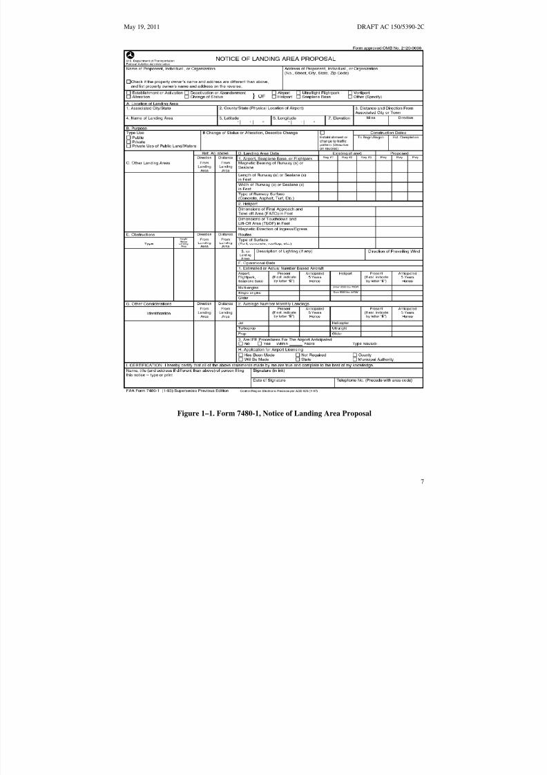
Activation, and Deactivation of Airports; sets requirements for persons proposing to construct, activate,deactivate, or alter a heliport to give advance notice of their intent to the FAA. This includes changing thesize or number of FATOs; adding, deleting, or changing an approach or departure route; or changingheliport status. An example of a heliport status change would be a change from private to public use orvice versa. When notification is required, file Form 7480-1 (see Figure 1–1 on page 7) with the appropriateFAA Airports Regional or District Office at least 90 days before construction, alteration, deactivation, or
change in use. See the FAA Airports web site at http://www.faa.gov/airports / for contact information.
a. The heliport layout diagram should be drawn to scale showing key dimensions, such as theTLOF size, FATO size, safety area size, distance from safety area perimeter to property edges, andapproach/departure paths in relation to buildings, trees, fences, power lines, obstructions, schools, churches,hospitals, residential communities, waste disposal sites, and other significant features as specified on Form7480-1 and as suggested in Figure 1–2 on page 8).
6
8/3/2019 draft_150_5390_2C
http://slidepdf.com/reader/full/draft15053902c 15/198
May 19, 2011 DRAFT AC 150/5390-2C
Figure 1–1. Form 7480-1, Notice of Landing Area Proposal
7

8/3/2019 draft_150_5390_2C
http://slidepdf.com/reader/full/draft15053902c 16/198
DRAFT AC 150/5390-2C May 19, 2011
EARHART AVENUE
AUTO PARKING AREA
C I T Y P R O P E R T Y N
OFFICE
FUTURE HELICOPTER PARKING
FATO LIGHTS
FLUSH TLOF PERIMETER LIGHTS
LANDING DIRECTION
C I T Y P R O P E R T Y
APPROACH/ DEPARTURE
DEPARTUREAPPROACH/
LIGHTSTLOF
SURFACE
SURFACE IN-GROUND FATO EDGE MARKERS
SAFETY AREA
HELIPORT PROPERTY LINE
Note: Layout diagrams should be drawn to scale with key dimensions shown as TLOF size, FATOsize, Safety Area size, distances from safety area perimeter to property edges, etc.
Figure 1–2. Example of a Heliport Layout Diagram
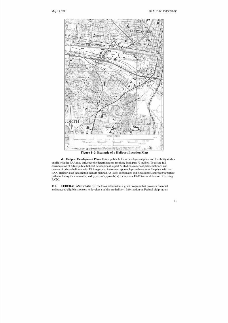
b. The preferred type of location map is the 7.5-minute U.S. Geological Survey Quadrangle Map,available from the US Geological Survey at nationalmap.gov. Web-based maps are also acceptable. Themap should show the location of the heliport site and the approach/departure paths. Point out the heliportsite on this map with an arrow. Indicate the latitude and longitude of the proposed heliport in North
American Datum of 1983 (NAD-83) coordinates (see Figure 1–3 on page 11).
c. The FAA Role. The FAA will conduct an aeronautical study of the proposed heliport underpart 157. Part 157 states: “The FAA will conduct an aeronautical study of an airport proposal and, afterconsultations with interested persons, as appropriate, issue a determination to the proponent and advisethose concerned of the FAA determination. The FAA will consider matters such as the effects theproposed action would have on existing or contemplated traffic patterns of neighboring airports; theeffects the proposed action would have on the existing airspace structure and projected programs of theFAA; and the effects that existing or proposed manmade objects (on file with the FAA) and natural
8

8/3/2019 draft_150_5390_2C
http://slidepdf.com/reader/full/draft15053902c 17/198
May 19, 2011 DRAFT AC 150/5390-2C
objects within the affected area would have on the airport proposal. While determinations consider theeffects of the proposed action on the safe and efficient use of airspace by aircraft and the safety of personsand property on the ground, the determinations are only advisory. Except for an objectionabledetermination, each determination will contain a determination-void date to facilitate efficient planning of the use of the navigable airspace. A determination does not relieve the proponent of responsibility forcompliance with any local law, ordinance or regulation, or state or other Federal regulation. Aeronautical
studies and determinations will not consider environmental or land use compatibility impacts”.
d. Penalty for Failure to Provide Notice. Persons who fail to give notice are subject to civilpenalty under 49 USC 46301, Civil Penalties of not more than $25,000 (or $1,100 if the person is anindividual or small business concern).
e. Notice Exemptions. Paragraph 157.1, Applicability, of part 157 exempts sites meeting one of the conditions below from the requirement to submit notice. However, these exemptions do not negate anotice or formal approval requirement prescribed by state law or local ordinance. For the purposes of applying the part 157 exemption criteria cited in (2) and (3) below, a landing and associated takeoff isconsidered to be one operation.
(1) A heliport subject to conditions of a Federal agreement that requires an approved currentheliport layout plan to be on file with the FAA.
(2) A heliport at which flight operations will be conducted under visual flight rules (VFR)and that is used or intended to be used for a period of less than 30 consecutive days with no more than 10operations per day.
(3) The intermittent use of a site that is not an established airport, that is used or intended tobe used for less than 1 year, and at which flight operations will be conducted only under VFR. For thepurpose of this part, “intermittent use of a site” means:
(a) the site is used or is intended to be used for no more than 3 days in any one week and
(b) no more than 10 operations will be conducted in any one day at that site.
109. HAZARDS TO AIR NAVIGATION. Title 14 CFR part 77, Safe, Efficient Use, and
Preservation of the Navigable Airspace, establishes requirements for notification to the FAA of objectsthat may affect navigable airspace. It sets standards for determining obstructions to navigable airspaceand provides for aeronautical studies of such obstructions to determine their effect on the safe andefficient use of airspace. Part 77 applies only to public airports and heliports, and private airports andheliports with at least one FAA-approved instrument approach procedure (See Figure 1–4 on page 13).
a. FAA Studies.
(1) Part 77. Objects that are obstructions to surfaces defined in part 77 are presumed to behazards unless an FAA study determines otherwise. The FAA conducts aeronautical studies to determinethe physical and electromagnetic effect on the use of navigable airspace, air navigational facilities, publicairports and heliports, and private airports and heliports with at least one FAA-approved instrumentapproach procedure. Public agencies are encouraged to enact zoning ordinances to prevent man-madefeatures from becoming hazards to navigation.
9

8/3/2019 draft_150_5390_2C
http://slidepdf.com/reader/full/draft15053902c 18/198
DRAFT AC 150/5390-2C May 19, 2011
(2) Part 157. While the FAA performs aeronautical studies under part 157 (see paragraph108.c above), such studies do not identify hazards to private facilities that do not have an FAA-approvedinstrument approach.
b. Mitigation of Hazards. The adverse effect of an object presumed or determined to be ahazard to air navigation may be mitigated by:
(1) Removing the object
(2) Altering the object, e.g. reducing its height
(3) Marking and/or lighting the object, provided an FAA aeronautical study has determinedthat the object would not be a hazard to air navigation if it were marked and lighted. Guidance on markingand lighting objects is contained in AC 70/7460-1, Obstruction Marking and Lighting.
c. Notification Requirements. Part 77 requires persons proposing certain construction oralteration to give 45-days notice to the FAA of their intent. Notification of the proposal should be madeon FAA Form 7460-1, Notice of Proposed Construction or Alteration. See https://oeaaa.faa.gov for more
information and to download the form.
10
8/3/2019 draft_150_5390_2C
http://slidepdf.com/reader/full/draft15053902c 19/198
May 19, 2011 DRAFT AC 150/5390-2C
Figure 1–3. Example of a Heliport Location Map
d. Heliport Development Plans. Future public heliport development plans and feasibility studies
on file with the FAA may influence the determinations resulting from part 77 studies. To assure fullconsideration of future public heliport development in part 77 studies, owners of public heliports andowners of private heliports with FAA-approved instrument approach procedures must file plans with theFAA. Heliport plan data should include planned FATO(s) coordinates and elevation(s), approach/departurepaths including their azimuths, and type(s) of approach(es) for any new FATO or modification of existingFATO.
110. FEDERAL ASSISTANCE. The FAA administers a grant program that provides financialassistance to eligible sponsors to develop a public use heliport. Information on Federal aid program
11

8/3/2019 draft_150_5390_2C
http://slidepdf.com/reader/full/draft15053902c 20/198
DRAFT AC 150/5390-2C May 19, 2011
eligibility requirements is available from FAA Airports Regional and District Offices and on the FAAAirports web site, www.faa.gov/airports.
111. ENVIRONMENTAL IMPACT ANALYSES. The National Environmental Policy Act of 1969requires consideration of potential environmental impacts prior to agency decision making, including, forexample, the decision to fund or approve a project, plan, license, permit, certification, rulemaking, or
operations specification, unless these actions are within an existing categorical exclusion and noextraordinary circumstances exist. Actions that may require an environmental assessment are normallyassociated with Federal grants or heliport layout plan approvals leading to the construction of a newheliport or significant expansion of an existing heliport.
a. Assessment Items. An environmental assessment should address noise, historic and culturalresources, wildlife, energy conservation, land usage, air quality, water quality, pollution prevention, lightemissions and other visual effects, electromagnetic fields, other public health and safety issues, the “noaction” alternative and a reasonable range of feasible alternatives, including mitigation not integrated intothe alternative initially. It should also describe the action taken to ensure public involvement and citizenparticipation in the planning process. An opportunity for a public hearing may be required for thefederally funded development of, or significant improvement to, an existing heliport.
b. Guidance. FAA Order 5050.4, National Environmental Policy Act (NEPA) Implementing
Instructions for Airport Projects, and FAA Order 1050.1, Polices and Procedures for Considering
Environmental Impacts, and other supplemental guidance from FAA Air Traffic and Flight Standardsprovide guidance on environmental impact analysis. State and local governments, including metropolitanplanning organizations and local transit agencies, should be contacted directly as they may also require anenvironmental report. The procedures in AC 150/5020-1, Noise Control and Compatibility Planning for
Airports, describe a means of assessing the noise impact. Contact the appropriate FAA Airports Regionalor District for current information related to assessing noise impact of heliports. Proponents of non-Federally assisted heliports should work with local governmental authorities concerning environmentalissues.
112. ACCESS TO HELIPORTS BY INDIVIDUALS WITH DISABILITIES. Congress has passedvarious laws concerning access to airports. Since heliports are a type of airport, these laws are similarlyapplicable. Guidance is contained in AC 150/5360-14, Access to Airports by Individuals with Disabilities.
113. STATE ROLE. Many state departments of transportation, aeronautical commissions, or similarauthorities require prior approval and, in some instances, a license for the establishment and operation of a heliport. Several states administer a financial assistance program similar to the Federal program and arestaffed to provide technical advice. Heliport proponents should contact their respective state aeronauticscommissions or departments for particulars on licensing and assistance programs.
12

8/3/2019 draft_150_5390_2C
http://slidepdf.com/reader/full/draft15053902c 21/198
May 19, 2011 DRAFT AC 150/5390-2C
200 FT
5000 FT
FINAL APPROACH ANDTAKEOFF AREA (FATO)
1
2
5
6
4
Notes:
required by 14 CFR part 77.9.).Building is less 200 ft [61 M] in height, but top will penetrate the 25:1 surface (Notice is
Antenna less than 200 ft [61 M] in height, but penetrates the 25:1 surface (Notice isrequired by 14 CFR part 77.9 (b) (3).).
Construction crane penetrates 25:1 surface (Notice is required by 14 CFR part 77.9 (b)(3).).
Building is less than 200 ft [61 ] in height and does not penetrate the 25:1 surface (Noticeis not required.).
Building is more than 5,000 ft [1,525 m] from heliport (Notice is required if building will be200 ft [61 M] or more in height.).
1
3
4
5
6
Note: Notice under 14 CFR part 77 required for all public-use heliports or a private use heliportwith at least one FAA-approved instrument approach procedure.
[ 1524 M]
61 M]
3
Antenna is over 200 ft [61 M] in height (Notice is required by 14 CFR part 77.9 (a)).2
Figure 1–4. Offsite Development Requiring Notice to the FAA
13

8/3/2019 draft_150_5390_2C
http://slidepdf.com/reader/full/draft15053902c 22/198
DRAFT AC 150/5390-2C May 19, 2011
114. LOCAL ROLE. Some communities have enacted zoning laws, building codes, fire regulations,etc. that can affect heliport establishment and operation. Some have or are in the process of developingcodes or ordinances regulating environmental issues such as noise and air pollution. A few localities haveenacted specific rules governing the establishment of a heliport. Therefore, heliport proponents shouldmake early contact with officials or agencies representing the local zoning board, the fire, police, orsheriff's department, and the elected person(s) who represent the area where the heliport is to be located.
115. RELATED/REFERENCED MATERIAL. The list of related/referenced publications isprovided in Appendix A on page 177.
14

8/3/2019 draft_150_5390_2C
http://slidepdf.com/reader/full/draft15053902c 23/198
May 19, 2011 DRAFT AC 150/5390-2C
CHAPTER 2. GENERAL AVIATION HELIPORTS 201. GENERAL. A General Aviation (GA) heliport accommodates helicopters used by individuals,corporations, and helicopter air taxi services. While GA heliports may be publicly owned, this is notrequired. Most GA heliports are privately owned. This chapter contains standards and recommendations
for designing all GA heliports. The design recommendations given in this chapter are based on theassumption that there will never be more than one helicopter within the final approach and takeoff area(FATO) and the associated safety area. If there is a need for more than one touchdown and liftoff area(TLOF) at a heliport, each TLOF must be located within its own FATO and within its own safety area.Figure 2-1 below illustrates the essential features of a GA heliport.
FATO APPROACH/DEPARTURESURFACE
TLOF
TLOF MARKING
SAFETY AREA
WINDCONE
APPROACH/DEPARTURESURFACE TDPC MARKING
HELIPORT IDENTIFICATION
MARKING
IN-GROUND FATO EDGE MARKINGNotes:
1. The wind cone must be located so that it will not interfere with the Approach/Departure Path orTransitional Surface.
2. TLOF size and weight limitation box omitted for clarity.
Figure 2-1. Essential Features of a GA Heliport: General Aviation
15

8/3/2019 draft_150_5390_2C
http://slidepdf.com/reader/full/draft15053902c 24/198
DRAFT AC 150/5390-2C May 19, 2011
202. PRIOR PERMISSION REQUIRED (PPR) FACILITIES. The standards in this AC arerecommended for all heliports. At heliports where the operator requires prior authorization for use, ensurethat pilots are thoroughly familiar with the heliport its procedures, and any facility limitations.
203. ACCESS BY INDIVIDUALS WITH DISABILITIES. Heliports operated by public entitiesand those receiving Federal financial assistance must meet accessibility requirements. See paragraph 112
above.
204. HELIPORT SITE SELECTION.
a. Long Term Planning. Public agencies and others planning to develop a GA heliport shouldconsider the possible future need for instrument operations and expansion.
b. Property Requirements. The property needed for a GA heliport depends upon the volume andtypes of users and the scope of amenities provided. Property requirements for helicopter operators and forpassenger amenities frequently exceed that required for “airside” purposes.
c. Turbulence. Air flowing around and over buildings, stands of trees, terrain irregularities, etc. can
create turbulence on ground-level and roof-top heliports that may affect helicopter operations. Where theFATO is located near the edge and top of a building or structure, or within the influence of turbulentwakes from other buildings or structures, the turbulence and airflow characteristics in the vicinity of, andacross the surface of the FATO should be assessed to determine if an air-gap between the roof, roof parapet or supporting structure, and/or some other turbulence mitigating design measure is necessary.FAA Technical Report FAA/RD-84/25, Evaluating Wind Flow Around Buildings on Heliport Placement
addresses the wind’s effect on helicopter operations. The following actions may be taken in selecting asite to minimize the effects of turbulence.
(1) Ground-Level Heliports. Helicopter operations from sites immediately adjacent tobuildings, trees, and other large objects are subjected to air turbulence effects caused by such features.Therefore, locate the landing and takeoff area away from such objects in order to minimize air turbulence
in the vicinity of the FATO and the approach/departure paths.
(2) Elevated Heliports. Establishing a 6 foot (1.8 m) or more air gap above the level of the roof will generally minimize the turbulent effect of air flowing over the roof edge. If an air gap or some otherturbulence mitigating design measure is warranted but not practical, operational limitations may need tobe considered under certain wind conditions. If an air gap is included in the design it should be kept freeat all times of significant objects that would obstruct the airflow.
205. BASIC LAYOUT. The heliport consists of a TLOF contained within a FATO. A safety area isprovided around the FATO. Table 2-1 shows how the minimum recommended safety area width varies asa function of heliport markings. The relationship of the TLOF to the FATO and the safety area is shownin Figure 2-2 on page 18. A FATO may not contain more than one TLOF. Appropriateapproach/departure airspace to allow safe approaches to and departures from landing sites is required. Tothe extent feasible, the preferred approach/departure path should be aligned with the predominant winds.See paragraph 209 below.
16

8/3/2019 draft_150_5390_2C
http://slidepdf.com/reader/full/draft15053902c 25/198
May 19, 2011 DRAFT AC 150/5390-2C
Table 2-1. Minimum VFR Safety Area Width as a Function of General Aviation and PPR Heliport Markings
GA heliports: 1/3 RD butnot less than20 ft (6 m)
1/3 RD butnot less than30 ft (9 m)
½ D butnot less than20 ft (6 m)
½ D butnot less than30 ft (9 m)
PPR heliports: 1/3 RD butnot less than
10 ft (3 m) **
1/3 RD butnot less than20 ft (6 m)**
½ D butnot less than20 ft (6 m)
½ D butnot less than30 ft (9 m)
TLOF perimeter marked:
FATO perimeter marked:
Std. “H” marking:
Yes
Yes
Yes
Yes
Yes
No
No
Yes
Yes
No
Yes
No
D: Overall length of the design helicopter
RD: Rotor diameter of the design helicopter
** Also applies to PPR heliports when the FATO is not marked. The FATO should not be marked if (a)the FATO (or part of the FATO) is a non-load bearing surface and/or (b) the TLOF is elevated above thelevel of a surrounding load bearing area.
206. TOUCHDOWN AND LIFTOFF AREA (TLOF).
a. TLOF Location. The TLOF of a GA heliport may be at ground level, on an elevated structure, orat rooftop level. The TLOF is normally centered within the FATO. At a PPR rooftop or other PPRelevated facility, where the entire FATO is not load-bearing, there are operational advantages if the TLOFis located in a load-bearing area that is as large as possible. In this case, the TLOF should be located inthe center of the load-bearing area.
(1) TLOF Size. The minimum TLOF dimension (length, width, or diameter) is equal to the RDof the design helicopter. TLOFs may be circular, however it is strongly recommended that new TLOFsshould be square or rectangular, as a square or rectangular shape provides the pilot with better visual cues
than a circular shape. Increasing the load-bearing area (LBA) centered on the TLOF may provide somesafety and operational advantages. At PPR facilities, if only a portion of the TLOF is paved, the minimumlength and width of this paved portion should be not less than two times the maximum dimension (lengthor width) of the undercarriage of the design helicopter. The center of this paved portion of the TLOFshould be the center of the TLOF. To avoid the risk of catching a skid and the potential for a dynamicrollover, there should be no difference in elevation between the paved and unpaved portions of the TLOF.
(2) Elevated GA Heliport. If the FATO outside the TLOF is not load-bearing, the minimumwidth, length or diameter of the TLOF is increased to the overall length (D) of the design helicopter. Seeparagraph 207.b(3) on page 23.
(3) Elevated PPR Heliports. At PPR rooftop or elevated facilities, the TLOF may be a
minimum of two times the maximum dimension (length or width) of the undercarriage of the designhelicopter if the height of the TLOF surface above the surrounding area is no greater than 30 inches(76 cm), and there is a solid surrounding area equal to the rotor diameter (RD) able to support 20 lbs/ft 2
(98 kg/m2) live load. The center of the load bearing area of the TLOF should be the center of the FATO.
17

8/3/2019 draft_150_5390_2C
http://slidepdf.com/reader/full/draft15053902c 26/198
See Table 2-1
Figure 2-
DRAFT AC 150/5390-2C May 19, 2011
TLOF
FATO
DIM
A
B
C
E
F
ITEM
Minimum TLOF Length
VALUE
1 RD
1 RD
1.5 D
1.5 D
G
Minimum TLOF Width
Minimum FATO Width
Minimum FATO Length
Minimum Safety Area Width
Minimum Separation
Between the Perimeters
See Paragraph 207.a.(1) and
of elevations above 1000'5 for adjustments
.75 D - .5 RD
NOTES
of the TLOF and FATO
B
E
F
A C
GSAFETY AREA
Note: For circular TLOFs and FATOs, dimensions A, B, C and E refer to diameters.
Figure 2-5
Table 2-1.
Figure 2-2. TLOF/FATO Safety Area Relationships and Minimum Dimensions:
General Aviation
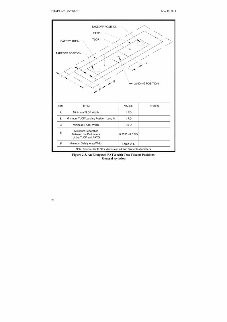
(4) Elongated TLOF. An elongated TLOF can provide an increased safety margin and greateroperational flexibility. An elongated TLOF may contain a landing position located in the center and twotakeoff positions located at either end. The landing position must have a minimum length equal to the RDof the design helicopter. If an elongated TLOF is provided, an elongated FATO is also required. Figure2-3 on page 20 shows an elongated TLOF and an elongated FATO.
18

8/3/2019 draft_150_5390_2C
http://slidepdf.com/reader/full/draft15053902c 27/198
May 19, 2011 DRAFT AC 150/5390-2C
b. Ground-level TLOF Surface Characteristics.
(1) Design Loads. The TLOF and any supporting TLOF structure must be capable of supportingthe dynamic loads of the design helicopter.
(2) Paving. The TLOF surface must be either paved or aggregate-turf (see AC 150/5370-10,
Standards for Specifying Construction of Airports items P-217 and P-501). Portland cement concrete(PCC) is recommended for ground-level facilities. An asphalt surface is less desirable for heliports as itmay rut under the wheels or skids of a parked helicopter. This has been a factor in some rolloveraccidents. Pavements should have a broomed or other roughened finish that provides a skid-resistantsurface for helicopters and non-slippery footing for people. For PPR heliports where only a portion of theTLOF is paved, the paved portion should be dynamic load-bearing and the surrounding area of the TLOFmust be designed for the static loads of the design helicopter.
c. Rooftop and Other Elevated TLOFs.
(1) Design Loads. Elevated TLOFs and any TLOF supporting structure must be capable of supporting the dynamic loads of the design helicopter described in paragraph 707.b on page 174. An
elevated heliport is illustrated in Figure 2-4 on page 21.
(2) Elevation. The TLOF must be elevated above the level of any obstacle in the FATO andsafety area that cannot be removed, except for frangibly mounted objects that, due to their function, mustbe located within the safety area (see paragraph 208.c on page 24).
(3) Obstructions. Elevator penthouses, cooling towers, exhaust vents, fresh-air vents, and otherraised features can affect heliport operations. Control mechanisms should be established to ensure thatobstruction hazards are not installed after the heliport is operational.
(4) Air Quality. Helicopter exhaust can affect building air quality if the heliport is too close tofresh air vents. When designing a building intended to support a helipad, locate fresh air vents
accordingly. When adding a heliport to an existing building, fresh air vents may have to be relocated.
(5) TLOF Surface Characteristics. Rooftop and other elevated heliport TLOFs should beconstructed of metal or concrete (or other materials subject to local building codes). TLOF surfaces musthave a finish that provides a skid-resistant surface for helicopters and non-slippery footing for people.
(6) Safety Net. If the platform is elevated 4 feet (1.2 m) or more above its surroundings, title 29CFR part 1910.23, Guarding Floor and Wall Openings and Holes, requires the provision of fallprotection. The FAA recommends that such protection be provided for all platforms elevated 30 inches(76 cm) or more. However, permanent railings or fences must not be used since they would be safetyhazards during helicopter operations. An alternate method of installing a safety net, meeting state andlocal regulations but not less than 5 feet (1.5 m) wide, is suggested. The safety net should have a loadcarrying capability of 25 lbs/ft2 (122 kg/m2). The net, as illustrated in Figure 2-27 on page 55, must notproject above the level of the TLOF. Both the inside and outside edges of the safety net should befastened to a solid structure. Nets should be constructed of material that is resistant to environmentaleffects.
19
8/3/2019 draft_150_5390_2C
http://slidepdf.com/reader/full/draft15053902c 28/198
See Table 2-1
DRAFT AC 150/5390-2C May 19, 2011
DIM
A
B
C
E
ITEM VALUE
1 RD
1 RD
1.5 D
F
NOTES
A
B
C
E
F
E
F
TAKEOFF POSITION
TAKEOFF POSITION
Minimum TLOF Width
Minimum TLOF/Landing Position Length
Minimum FATO Width
Minimum Safety Area Width
Minimum Separation
Between the Perimetersof the TLOF and FATO
0.75 D - 0.5 RD
Table 2-1.
FATO
TLOF
LANDING POSITION
SAFETY AREA
Note: For circular TLOFs, dimensions A and B refer to diameters.
Figure 2-3. An Elongated FATO with Two Takeoff Positions: General Aviation
20

8/3/2019 draft_150_5390_2C
http://slidepdf.com/reader/full/draft15053902c 29/198
May 19, 2011 DRAFT AC 150/5390-2C
HELIPORT BEACON
LIGHTED WIND CONE
FATO
RAISED TLOF
5 FT [1.5 M] WIDE
SAFETY NET
SAFETY AREA
FLUSH TLOFLIGHTING
RAMP
Post at Personnel Entrance
CAUTIONHELICOPTER LANDING
AREASAFETY
AVOID FRONT ANDREARAREA OF HELICOPTER
STAY CLEAROFTHE
AVOID FRONT ANDREAR TAIL ROTORAREA OF HELICOPTER Notes:
APPROACHAND LEAVEHELICOPTER FROM THESIDEIN A CROUCHED MANNERWHEN ROTORSARETURNING
Fiigure 2-271. See F gure 2-26 for detailed views of the safetyINSTRUCTIONS net and lighting.
AUTHORIZEDPERSONNEL 2. TLOF size and weight limitation box is not
ONLY shown for clarity.
Figure 2-4. Elevated Heliport: General Aviation
21
8/3/2019 draft_150_5390_2C
http://slidepdf.com/reader/full/draft15053902c 30/198
DRAFT AC 150/5390-2C May 19, 2011
(7) Access to Elevated TLOFs. Title 29 CFR part 1936, Means of Egress, requires two separateaccess points for an elevated structure such as one supporting an elevated TLOF. If stairs are used, theymust be built in compliance with title 29 CFR part 1910.24, Fixed Industrial Stairs. Handrails required bythis standard must fold down or be removable to below the level of the TLOF so that they will not behazards during helicopter operations.
d. TLOF Gradients. Recommended TLOF gradients are defined in paragraph 702 on page 173.
207. FINAL APPROACH AND TAKEOFF AREA (FATO). A general aviation heliport must haveat least one FATO. The FATO must contain a TLOF within its borders at which arriving helicoptersterminate their approach and from which departing helicopters take off.
a. FATO Size.
(1) The minimum width, length or diameter of a FATO is 1.5 times the overall length (D) of thedesign helicopter. A circular FATO is only used when the TLOF is circular. At elevations well above sealevel, a longer FATO is needed to provide an increased safety margin and greater operational flexibility.The additional FATO length is depicted in Figure 2-5 on page 23. Where the operator of a PPR heliport
chooses not to provide additional FATO length, the operator should ensure that all pilots using the facilityare thoroughly knowledgeable with this and any other facility limitations.
(2) The minimum distance between the TLOF perimeter and the FATO perimeter must be notless than the distance (0.75D - 0.5RD) where D is the overall length and RD is the rotor diameter of thedesign helicopter. The relationship of the TLOF to the FATO and the safety area is shown in Figure 2-2on page 18.
b. FATO Surface Characteristics.
(1) Ground Level GA Heliports. If the TLOF is marked, the FATO outside the TLOF must becapable of supporting the static loads of the design helicopter as described in paragraph 707.a. If the
TLOF is not marked (see paragraph 214.b below) and/or it is intended that the helicopter can landanywhere within the FATO, the FATO outside the TLOF and any FATO supporting structure must, likethe TLOF, be capable of supporting the dynamic loads of the design helicopter as described in paragraph707.b.
(2) Ground Level PPR Heliports. For ground level PPR heliports, if the TLOF is marked, theFATO outside the TLOF need not be load-bearing providing it is a solid area able to support a 20lbs/ft2
(98 kg/m2) live load. If the TLOF is not marked and/or it is intended that the helicopter can land anywherewithin the FATO, the FATO outside the TLOF should, like the TLOF, be capable of supporting thedynamic loads of the design helicopter.
22
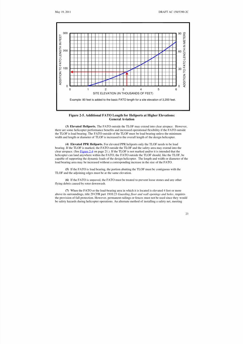
8/3/2019 draft_150_5390_2C
http://slidepdf.com/reader/full/draft15053902c 31/198
May 19, 2011 DRAFT AC 150/5390-2C
300
200
100
0 0 1 2 3 4 5 6 0
90
60
30
A D D I T I O N T O F A T O L E N G T H I N
F E E T
A
D D I T I O N T O F A T O L E N G T H I N M
E T E R S
SITE ELEVATION (IN THOUSANDS OF FEET)
Example: 80 feet is added to the basic FATO length for a site elevation of 3,200 feet.
Figure 2-5. Additional FATO Length for Heliports at Higher Elevations: General Aviation
(3) Elevated Heliports. The FATO outside the TLOF may extend into clear airspace. However,
there are some helicopter performance benefits and increased operational flexibility if the FATO outsidethe TLOF is load bearing. The FATO outside of the TLOF must be load bearing unless the minimumwidth and length or diameter of TLOF is increased to the overall length of the design helicopter.
(4) Elevated PPR Heliports. For elevated PPR heliports only the TLOF needs to be loadbearing. If the TLOF is marked, the FATO outside the TLOF and the safety area may extend into theclear airspace. (See Figure 2-4 on page 21.). If the TLOF is not marked and/or it is intended that thehelicopter can land anywhere within the FATO, the FATO outside the TLOF should, like the TLOF, becapable of supporting the dynamic loads of the design helicopter. The length and width or diameter of theload bearing area may be increased without a corresponding increase in the size of the FATO.
(5) If the FATO is load bearing, the portion abutting the TLOF must be contiguous with the
TLOF and the adjoining edges must be at the same elevation.
(6) If the FATO is unpaved, the FATO must be treated to prevent loose stones and any otherflying debris caused by rotor downwash.
(7) When the FATO or the load-bearing area in which it is located is elevated 4 feet or moreabove its surroundings, title 29 CFR part 1910.23 Guarding floor and wall openings and holes, requiresthe provision of fall protection. However, permanent railings or fences must not be used since they wouldbe safety hazards during helicopter operations. An alternate method of installing a safety net, meeting
23

8/3/2019 draft_150_5390_2C
http://slidepdf.com/reader/full/draft15053902c 32/198
DRAFT AC 150/5390-2C May 19, 2011
state and local regulations but not less than 5 feet (1.5 m) wide, is suggested. The safety net should have aload carrying capability of 25 lbs/ft2 (122 kg/m2). The net, as illustrated in Figure 2-27 on page 55, mustnot project above the level of the TLOF. Both the inside and outside edges of the safety net should befastened to a solid structure. Nets should be constructed of material that is resistant to environmentaleffects.
c. Mobile Objects within the FATO. The FATO design recommendations of this AC are based onthe assumption that the TLOF and FATO are closed to other aircraft if a helicopter or other mobile objectis within the FATO or the safety area.
d. Fixed Objects within the FATO. No fixed objects are permitted within a FATO except forfrangibly mounted objects that, due to their function, must be located there. Those objects whosefunctions require them to be located within the FATO must not exceed a height of 2 inches (5 cm) abovethe elevation of the TLOF perimeter.
e. FATO/FATO Separation. If a heliport has more than one FATO, the separation between theperimeters of the two FATOs must be such that the respective safety areas do not overlap. This separationis based on the assumption that simultaneous approach/departure operations will not take place. If
simultaneous operations are planned, a minimum 200 foot (61 m) separation is required.
f. FATO Gradients. Recommended FATO gradients are defined in paragraph 703 on page 173.
208. SAFETY AREA. A safety area surrounds a FATO.
a. Safety Area Width. The required width of the safety area is shown in Table 2-1 on page 17, andis the same on all sides. The width is affected by the provision or absence of standard heliport markings.The safety area may extend into clear airspace.
b. Mobile Objects within the Safety Area. The safety area design recommendations of this AC arebased on the assumption that the TLOF and FATO are closed to other aircraft if a helicopter or other
mobile object is within the FATO or the safety area.
c. Fixed Objects Within a Safety Area. No fixed objects are permitted within a safety area exceptfor frangibly mounted objects that, due to their function, must be located there. Those objects whosefunctions require them to be located within the safety area must not exceed a height of 8 inches (20 cm)above the elevation of the FATO perimeter nor penetrate the approach/departure surfaces or transitionalsurfaces.
d. Safety Area Surface. The safety area need not be load bearing. Figure 2-6 on page 25 depicts asafety area extending over water. If possible, the portion of the safety area abutting the FATO should becontiguous with the FATO with the adjoining edges at the same elevation. This is needed to avoid the risk of catching a helicopter skid or wheel. The safety area should be treated to prevent loose stones and anyother flying debris caused by rotor wash.
e. Safety Area Gradients. Recommended safety area gradients are defined in Chapter 7 on page173.
209. VFR APPROACH/DEPARTURE PATHS. The purpose of approach/departure airspace, shownin Figure 2-7 on page 27, is to provide sufficient airspace clear of hazards to allow safe approaches to anddepartures from the TLOF.
24

8/3/2019 draft_150_5390_2C
http://slidepdf.com/reader/full/draft15053902c 33/198
May 19, 2011 DRAFT AC 150/5390-2C
PIERTAXIWAY
FATO EXTENDSBEYOND PIER
ON-SHOREPARKING APRON
SAFETY ZONEEXTENDS BEYOND PIER
TLOF
Note: Some markings omitted for clarity.
Figure 2-6. Non-load-bearing FATO and Safety Area: General Aviation
25

8/3/2019 draft_150_5390_2C
http://slidepdf.com/reader/full/draft15053902c 34/198
DRAFT AC 150/5390-2C May 19, 2011
a. Number of Approach/Departure Paths. Preferred approach/departure paths should be alignedwith the predominant wind direction so that downwind operations are avoided and crosswind operationsare kept to a minimum. To accomplish this, a heliport should have more than one approach/departurepath. Other approach/departure paths should be based on the assessment of the prevailing winds or, whenthis information is not available, the separation between such flight paths and the preferred flight pathshould be at least 135 degrees. See Figure 2-7 on page 27, Figure 2-8 on page 28, and Figure 2-9 on page
29. At a PPR heliport that has only one approach/departure path, the operator should ensure that all pilotsusing the facility are thoroughly knowledgeable with this and any other facility limitations. A secondflight path provides additional safety margin and operational flexibility.
b. VFR Approach/Departure and Transitional Surfaces. Figure 2-7 on page 27 illustrates theapproach/departure and transitional surfaces.
(1) An approach/departure surface is centered on each approach/departure path. Theapproach/departure path starts at the edge of the FATO and slopes upward at 8:1 (8 units horizontal in 1unit vertical) for a distance of 4000 feet (1219 m) where the width is 500 feet (152 m) at a height of 500feet (152 m) above the heliport elevation.
(2) The transitional surfaces start from the edges of the FATO parallel to the flight path centerline, and from the outer edges of the 8:1 approach/departure surface, and extend outwards at a slope of 2:1(2 units horizontal in 1 unit vertical) for a distance of 250 feet (76 m) from the centerline. The transitionalsurface is not applied on the FATO edge opposite the approach/departure surface.
(3) The approach/departure and transitional surfaces must be free of penetrations unless an FAAaeronautical study determines such penetrations not to be hazards. Such aeronautical studies areconducted only at public heliports and private airports with FAA-approved approach procedures.Paragraph 109 on page 9 provides additional information on hazards to air navigation.
(4) At PPR facilities, the size of the 8:1 approach/departure surface may be increased for adistance of 2,000 feet (610 m) as shown in Figure 2-9 on page 29 and Figure 2-11 on page 32 in lieu of
considering transitional surfaces. The lateral extensions on each side of the 8:1 approach/departuresurface start at the width of the FATO and are increased so that at a distance of 2,000 feet (610 m) fromthe FATO they are 100 feet (30 m) wide. Penetrations of obstacles into area A or area B, but not both,may be allowed providing the penetrations are marked or lighted and not considered a hazard.
c. Curved VFR Approach/Departure Paths. VFR approach/departure paths may include onecurve. Such paths may use the airspace above public lands, such as freeways or rivers. However, thedesign of curved approach/departure paths must consider the performance capabilities of the helicoptersintended to be served by the heliport. Where a curved portion of the approach/departure path is provided,the sum of the radius of arc defining the center line and the length of the straight portion originating at theFATO must not be less than 1886 feet (575 m). The minimum radius for curved approach/departure pathsis 886 feet (270m) following a 1000 feet (305m) straight section. The combined length of the center line
of the curved portion and the straight portion must be 4000 feet (1219 m). See Figure 2-8 on page 28.Figure 2-10 on page 30 shows a curved approach/departure path for an 8:1 approach/departure surface.
26

8/3/2019 draft_150_5390_2C
http://slidepdf.com/reader/full/draft15053902c 35/198
May 19, 2011 DRAFT AC 150/5390-2C
FATO
PREDOMINATE WIND DIRECTIONSURFACE BASED UPON THE
PREFERRED APPROACH/DEPARTURE
APPROACH/ DEPARTURE
SURFACE(TYPICAL)
SEE DETAIL
OPPOSITE
HELIPORT
135°
SHADED AREATO HAVE SAME
CHARACTERISTICS
AS FATO
250 FT [76 M]
500 FT [152 M]
500 FT[152 M]
4,000 FT[1,219 M]
LEGEND
8:1 Approach/Departure
Surface250 FT FATO
[76 M]2:1 Transitional Surface
500 FT
[152 M]
Note: Not drawn to scale
Figure 2-7. VFR Heliport Approach/Departure and Transitional Surfaces: General Aviation
27
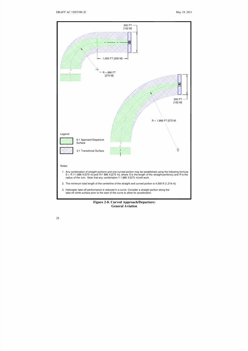
8/3/2019 draft_150_5390_2C
http://slidepdf.com/reader/full/draft15053902c 36/198
DRAFT AC 150/5390-2C May 19, 2011
500 FT
[152 M]
1,000 FT [305 M]
R = 886 FT
[270 M]
500 FT
[152 M]
R = 1,886 FT [575 M]
Legend:
8:1 Approach/DepartureSurface2:1 Transitional Surface
Notes:
1. Any combination of straight portions and one curved portion may be established using the following formula:S + R 1,886 ft [575 m] and R 886 ft [270 m], where S is the length of the straight portion(s) and R is the
radius of the turn. Note that any combination 1,886 ft [575 m] will work.
2. The minimum total length of the centerline of the straight and curved portion is 4,000 ft [1,219 m].
3. Helicopter take-off performance is reduced in a curve. Consider a straight portion along the take-off climb surface prior to the start of the curve to allow for acceleration.
Figure 2-8. Curved Approach/Departure: General Aviation
28

8/3/2019 draft_150_5390_2C
http://slidepdf.com/reader/full/draft15053902c 37/198
P
E
8 : 1 A P P R O A C H / D E
A R T U R E S U R F A C
May 19, 2011 DRAFT AC 150/5390-2C
P e n e t r a t i o
n ( s ) o f A o r B a r e a b u t n o t b o t h a r e
a s a l l o w e d
i f m a r k e d o r l i g h t e d a n d i f n o t c o n s i d e r e d a
h a z a r d
1 0 0 F T [ 3 0 M ]
A
F A T O
5 0 0 F T
A P P R O A C H / D E P A R T U R E S U R F A C E
8 : 1
[ 1 5 2 M ]
B
1 0 0 F T [ 3 0 M ]
2 , 0 0 0 F T [ 6 1 0 M ]
4 , 0 0 0 F T [ 1 , 2 1 9 M ]
P L A N V I E W
2 , 0 0 0 F T [ 6 1 0 M ]
5 0 0 F T
[ 1 5 2 M ]
F A T O
2 5 0 F T [ 7 6 M ]
E L E V A T I O N V I E W
Figure 2-9. VFR PPR Heliport Lateral Extension of the 8:1 Approach/Departure Surface: General Aviation
29
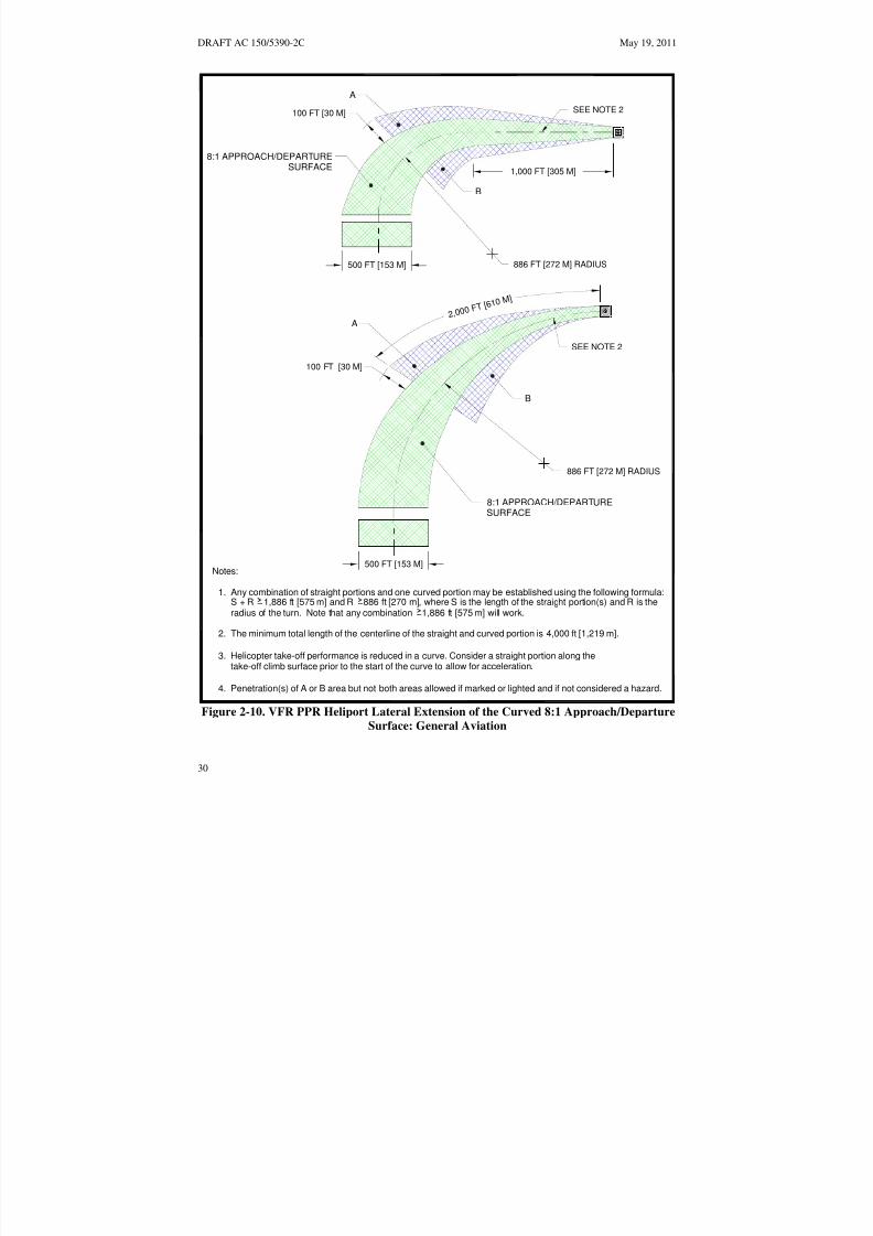
8/3/2019 draft_150_5390_2C
http://slidepdf.com/reader/full/draft15053902c 38/198
2, 0 0 0 F T [ 6 1
0 M ]
DRAFT AC 150/5390-2C May 19, 2011
A
SEE NOTE 2100 FT [30 M]
8:1 APPROACH/DEPARTURESURFACE
1,000 FT [305 M]
B
886 FT [272 M] RADIUS500 FT [153 M]
A
SEE NOTE 2
100 FT [30 M]
B
886 FT [272 M] RADIUS
8:1 APPROACH/DEPARTURESURFACE
500 FT [153 M]Notes:
1. Any combination of straight portions and one curved portion may be established using the following formula:S + R 1,886 ft [575 m] and R 886 ft [270 m], where S is the length of the straight portion(s) and R is theradius of the turn. Note that any combination 1,886 ft [575 m] will work.
2. The minimum total length of the centerline of the straight and curved portion is 4,000 ft [1,219 m].
3. Helicopter take-off performance is reduced in a curve. Consider a straight portion along the take-off climb surface prior to the start of the curve to allow for acceleration.
4. Penetration(s) of A or B area but not both areas allowed if marked or lighted and if not considered a hazard.
Figure 2-10. VFR PPR Heliport Lateral Extension of the Curved 8:1 Approach/Departure
Surface: General Aviation
30

8/3/2019 draft_150_5390_2C
http://slidepdf.com/reader/full/draft15053902c 39/198
May 19, 2011 DRAFT AC 150/5390-2C
d. Flight Path Alignment Guidance. Optional flight path alignment markings and/or flight pathalignment lights (see paragraph 214.e below) may be used where it is desirable and practicable to indicateavailable approach and/or departure flight path direction(s). See Figure 2-11 on page 32.
e. Periodic Review of Obstructions. Heliport operators should reexamine obstacles in the vicinityof 8:1 approach/departure paths on at least an annual basis. This reexamination should include an
appraisal of the growth of trees near approach and departure paths. Paragraph 109 on page 9 providesadditional information on hazards to air navigation.
210. HELIPORT PROTECTION ZONE (HPZ). It is recommended that a Heliport Protection Zonebe established for each approach/departure surface. The HPZ is the area under the 8:1 approach/departuresurface starting at the FATO perimeter and extending out for a distance of 280 feet (85.3 m), as illustratedin Figure 2-12 on page 33. The HPZ is intended to enhance the protection of people and property on theground. This is achieved through heliport owner control over the HPZ. Such control includes clearingHPZ areas (and maintaining them clear) of incompatible objects and activities. Land uses discouraged inthe HPZ are residences and places of public assembly. (Churches, schools, hospitals, office buildings,shopping centers, and other uses with similar concentrations of persons typify places of public assembly.)Fuel storage facilities should not be located in the HPZ.
211. WIND CONE.
a. Specification. A wind cone conforming to AC 150/5345-27, Specification for Wind Cone
Assemblies, must be used to show the direction and magnitude of the wind. The wind cone should providethe best possible color contrast to its background.
b. Wind Cone Location. The wind cone must be located so it provides the pilot with valid winddirection and speed information in the vicinity of the heliport under all wind conditions.
(1) At many landing sites, there may be no single, ideal location for the wind cone. At other sites,it may not be possible to site a wind cone at the ideal location. Consequently, more than one wind cone
may be required in order to provide the pilot with all the wind information needed for safe operations.
(2) A pilot on the approach path must be able to see a wind cone clearly when the helicopter is ata distance of 500 feet (152 m) from the TLOF.
(3) Pilots must also be able to see a wind cone from the TLOF.
(4) To avoid presenting an obstruction hazard, the wind cone(s) must be located outside thesafety area, and it must not penetrate the approach/departure or transitional surfaces.
c. Wind Cone Lighting. For night operations, the wind cone must be illuminated, either internallyor externally, to ensure that it is clearly visible.
212. TAXIWAYS AND TAXI ROUTES. Taxiways and taxi routes are provided for the movement of helicopters from one part of a landing facility to another. They provide a connecting path between theFATO and a parking area. They also provide a maneuvering aisle within the parking area. A taxi routeincludes the taxiway plus the appropriate clearances needed on both sides. The relationship between ataxiway and a taxi route is illustrated in Figure 2-13 on page 34, Figure 2-14 on page 35, and Figure 2-15on page 36. At heliports with no parking or refueling area outside the TLOF(s), no taxi route or taxiway isrequired.
31

8/3/2019 draft_150_5390_2C
http://slidepdf.com/reader/full/draft15053902c 40/198
DRAFT AC 150/5390-2C May 19, 2011
BIDIRECTIONAL AND SINGLE FLIGHT PATHS
SAFETY AREASINGLE FLIGHTPATH MARKING
FATOBI-DIRECTIONIONAL
FLIGHT PATH MARKING
TLOF
SEE DETAIL A
5 FT [1.5 M]10 FT [3.0 M]
MINIMUM
1.5 FT[0.46 M]
LIGHTS (3 MINIMUM)5 FT5 - 10 FT[1.5 M]
[1.5 - 3.0 M] SPACING
DETAIL A FLIGHT PATH ALIGNMENT MARKING DETAIL
Notes (arrow): Notes (lights):
1. Arrowheads must have constant 1. Light type: omni-directional inset whitedimensions lights
2. Stroke length may be adjusted to match length 2. Lights may be outside arrowavailable (Minimum length: 10 ft [3 m])
Figure 2-11. Flight Path Alignment Marking and Lights:
General Aviation
32
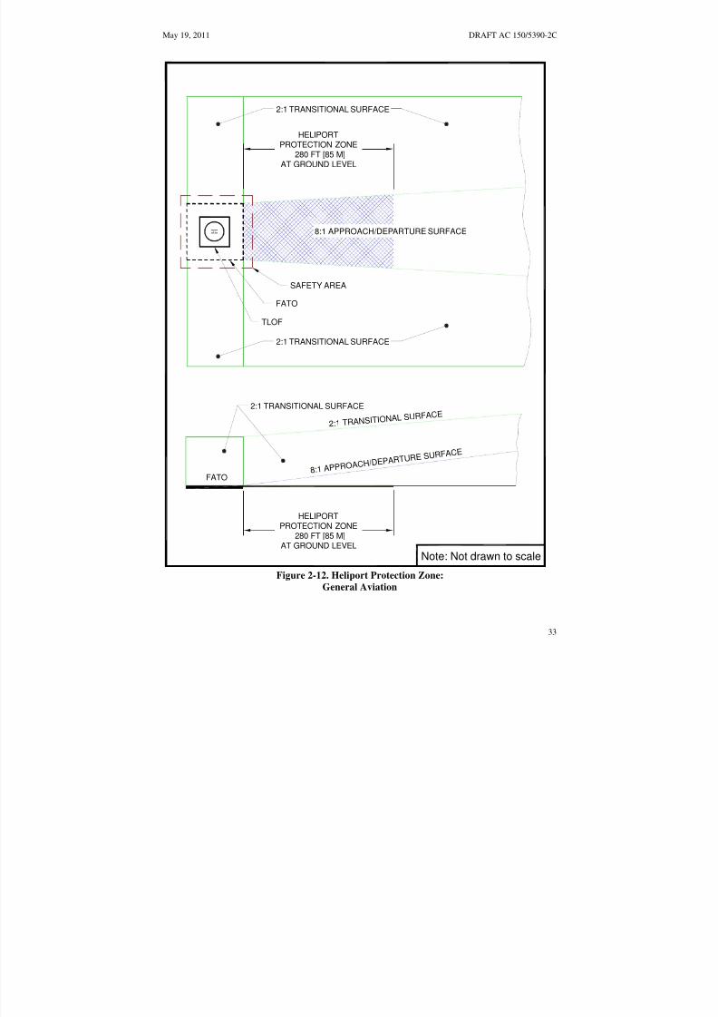
8/3/2019 draft_150_5390_2C
http://slidepdf.com/reader/full/draft15053902c 41/198
May 19, 2011 DRAFT AC 150/5390-2C
FATO
8:1 APPR OAC H
/DEPAR T URE S URFAC
E
2:1 TRANSITIONAL SURFACE
FATO
8:1 APPROACH/DEPARTURE SURFACE
2:1 TRANSITIONAL SURFACE
2:1 TRANSI TIONAL S
URFACE
SAFETY AREA
TLOF
2:1 TRANSITIONAL SURFACE
HELIPORTPROTECTION ZONE
280 FT [85 M]AT GROUND LEVEL
HELIPORTPROTECTION ZONE
280 FT [85 M]AT GROUND LEVEL
Note: Not drawn to scale
Figure 2-12. Heliport Protection Zone:
General Aviation
33

8/3/2019 draft_150_5390_2C
http://slidepdf.com/reader/full/draft15053902c 42/198
ABLE 2-2
DRAFT AC 150/5390-2C May 19, 2011
PAVED TAXIWAY WIDTH
NOT LESS THAN TWO TIMESTHE UNDERCARRIAGE WIDTHOF THE DESIGN HELICOPTER
TAXIWAY EDGE MARKING:TWO CONTINUOUS 6 IN [15 CM]
YELLOW LINES SPACED 6 IN [15 CM] APART
TAXI ROUTE WIDTHSEE T FOR
TAXIWAY/TAXI ROUTE WIDTH
TAXIWAY CENTERLINE MARKING:
CONTINUOUS 6 IN [15 CM] YELLOW LINE
Table 2-2
Figure 2-13. Taxiway/Taxi Route Relationship – Paved Taxiway: General Aviation
34

8/3/2019 draft_150_5390_2C
http://slidepdf.com/reader/full/draft15053902c 43/198
May 19, 2011 DRAFT AC 150/5390-2C
T A
X I W A Y R A I S E D E D G E M A R K E R S
S P
A C I N G : 1 5 F T [ 4 . 6 M ] O N S T R A I G H T S E G M E N T S
1 0
F T [ 3 . 0 M ] O N C U R V E D S E G M E N T S
U N P A V E D T A X I W A
Y W I D T H
1 R D B U T N O T
M O R E
T H A N 3 5 F T [ 1 0 . 7 M ]
T A X I W A Y / T A X I
R O U T E W I D T H
S E E T A B L E 2 - 2
T a b l e 2 - 2
4 I N [ 1 0 C M ] D I A X
6 I N [ 1 5 C M ] H I G H M A X
C Y L I N D E R O N A
2 I N [ 5 C M ] S U P P O R T
1 2 I N [ 3 0 C M ] M I N D I A D I S C
A T G R A D E O R
N O T T O
E X C E E D 3 I N [ 7 C M ]
T A X I W A Y R A I S E D
E D G E
M A R K E R D E T
A I L
N o t e : N o t d r a w n t o s c a l e
Figure 2-14. Taxiway/Taxi Route Relationship – Unpaved Taxiway with Raised Edge
Markers: General Aviation
35

8/3/2019 draft_150_5390_2C
http://slidepdf.com/reader/full/draft15053902c 44/198
DRAFT AC 150/5390-2C May 19, 2011
T A X I W A Y F L U S H I N - G R O U N D
E D G E M A R K E R S
5 F T
X 1 F T [ 1 . 5 M X 3 0 C M ]
S P A C I N G : 1 5 F T [ 4 . 6 M ] O N S
T R A I G H T S E G M E N T S
1 0 F T [ 3 . 0 M ] O N
C U R V E D S E G M E N T S
U N P A V E D T A X I W A Y W I D T H
2 X
U N D E R C A R R I A G E W I D T H
T A X I W A Y / T A X I
O F
T H E D E S I G N H E L I C O P T E R
R O
U T E W I D T H
S E E T A B L E 2 - 2
N o t e : N o t d r a
w n t o s c a l e
Figure 2-15. Taxiway/Taxi Route Relationship – Unpaved Taxiway with Flush Edge
Markers: General Aviation
36

8/3/2019 draft_150_5390_2C
http://slidepdf.com/reader/full/draft15053902c 45/198
May 19, 2011 DRAFT AC 150/5390-2C
a. Taxiway/Taxi Route Widths. The dimensions of taxiways and taxi routes are a function of helicopter size, taxiway/taxi route marking, and type of taxi operations (ground taxi versus hover taxi).These dimensions are defined in Table 2-2 on page 38. Normally, the requirement for hover taxi dictatesthe taxiway/taxi route widths. However, when the fleet comprises a combination of large ground taxiinghelicopters and smaller air taxiing helicopters, the larger aircraft may dictate the taxiway/taxi routewidths. If wheel-equipped helicopters taxi with wheels not touching the surface, the facility should be
designed with hover taxiway widths rather than ground taxiway widths. Where the visibility of thecenterline marking cannot be guaranteed at all times, such as locations where snow or dust commonlyobscure the centerline marking and it is not practical to remove it, the minimum taxiway/taxi routedimensions should be determined as if there was no centerline marking.
b. Surfaces. Ground taxiways must have a surface that is portland cement concrete, asphalt or asurface, such as turf, stabilized in accordance with the recommendations of items P-217 of AC150/5370-10. Unpaved portions of taxiways and taxi routes must have a turf cover or be treated in someway to prevent dirt and debris from being raised by a taxiing helicopter’s rotor wash.
c. Gradients. Recommended taxiway and taxi route gradients are defined in Chapter 7 on page 173.
213. HELICOPTER PARKING. If more than one helicopter at a time is expected at a heliport, thefacility should have an area designated for parking helicopters. The size of this area depends on thenumber and size of specific helicopters to be accommodated. It is not necessary that every parkingposition accommodate the design helicopter. Individual parking positions should be designed toaccommodate the helicopter size and weights expected to use the parking position at the facility.However, separation requirements between parking positions and taxi routes are based on the designhelicopter. Separation requirements between parking positions intended for helicopters of different sizesare based on the larger helicopter. Parking positions must support the static loads of the helicopterintended to use the parking area. Parking areas may be designed as one large, paved apron or asindividual, paved parking positions. Ground taxi turns of wheeled helicopters are significantly larger thana hover turn. Design of taxi intersections and parking positions for wheeled helicopters should considerthe turn radius of the helicopters. Heliport parking areas must be designed so that helicopters will be
parked in an orientation that keeps the “avoid areas” around the tail rotors (see Figure 2-16 on page 39,Figure 2-17 on page 40, and Figure 2-19 on page 42) clear of passenger walkways.
a. Location. Aircraft parking areas must not lie under an approach/departure surface. However,aircraft parking areas may lie under the transitional surfaces.
(1) The parking position must be located to provide a minimum distance between the tail rotorarc and any object, building, safety area, or other parking position. The minimum distance is 10 feet (3 m)for ground taxi operations and the greater of 10 feet (3 m) or 1/3 RD for hover taxi operations. See Figure2-19 on page 42.
(2) The parking position must be located to provide a minimum distance between the main rotor
arc and the edge of any taxi route. Parking positions may be designed such that the helicopter taxisthrough, turns around, or backs out to depart. The minimum distance is 1/3 RD for “turn around” and“taxi through” parking areas, and 1/2 RD for “back-out” parking areas. See Figure 2-16 on page 39,Figure 2-17 on page 40, and Figure 2-19 on page 42.
37

8/3/2019 draft_150_5390_2C
http://slidepdf.com/reader/full/draft15053902c 46/198
DRAFT AC 150/5390-2C May 19, 2011
Table 2-2. Taxiway / Taxi Route Dimensions – General Aviation Heliports
Taxiway
(TW)
Type
Minimum
Width of
Paved Area
Centerline
Marking
Type
TW
Edge
Marking
Type
Lateral Separation Between
TW Edge Markings
Total Taxi
Route Width
GroundTaxiway
2 x UC Painted
Painted 2 x UC
1.5 RD
Elevated1 RD but not greater than 35 ft(10.7 m)
Unpaved butstabilizedfor ground
taxi
None
Flush 2 x UC
Elevated1 RD but not greater than 35 ft(10.7 m)
HoverTaxiway
2 x UC Painted Painted 2 x UC
2RD
Unpaved NoneElevatedor Flush
1 RD but not greater than 35 ft(10.7 m)
RD: rotor diameter of the design helicopter
TW: taxiway
UC: undercarriage length or width (whichever is greater) of the design helicopter
38

8/3/2019 draft_150_5390_2C
http://slidepdf.com/reader/full/draft15053902c 47/198
May 19, 2011 DRAFT AC 150/5390-2C
TLOF EDGE MARKING FATO EDGE MARKING
APPROACH/DEPARTURESURFACE
APPROACH/DEPARTURESURFACE
SAFETY AREA
TAXI ROUTE WIDTH
1/3 RD TAXI ROUTE WIDTH
SEE NOTE 3
SHOULDER LINE
MARKING
1 RD CIRCLE PARKING POSITIONCENTERLINE (SOLID)
Notes:
1. Several markings (such as Parking Position Identifier and passenger walkways) have been omitted for clarity.
2. The parking positions are designed so that the helicopters exit taxiing forward.
3. Minimum recommended clearance between the arcs generated by the main rotor:Hover taxi operations: 1/3 RD of the larger helicopter Ground taxi operations: 10 ft [3 m]Figure 2-16. Parking Area Design – “Taxi-through” Parking Positions:
General Aviation
39

8/3/2019 draft_150_5390_2C
http://slidepdf.com/reader/full/draft15053902c 48/198
DRAFT AC 150/5390-2C May 19, 2011
PARKING POSITION
CENTERLINE (SOLID)
1 RD CIRCLE
SEENOTE 2
1/3 RD
TAIL ROTORARC
TDPC MARKING TAXI ROUTE WIDTH
SAFETY AREA
APPROACH/DEPARTURE APPROACH/DEPARTURESURFACE SURFACE
FATO EDGE MARKING TLOF EDGE MARKING
Notes:
1. Several markings (such as Parking Position Identifier and passenger walkways) have been omitted forclarity.
2. Minimum recommended clearance between the tail rotor arcs :Hover taxi operations: 1/3 RD of the larger helicopter, but not less than 10 ft [3 m].
Ground taxi operations: 10 ft [3 m]Figure 2-17. Parking Area Design – “Turn-around” Parking Positions:
General Aviation
40

8/3/2019 draft_150_5390_2C
http://slidepdf.com/reader/full/draft15053902c 49/198
May 19, 2011 DRAFT AC 150/5390-2C
PARKING POSITION
CENTERLINE (SOLID)
1 RD CIRCLE
SEENOTE 2
1/2 RD
SHOULDERLINE MARKING
TAXI ROUTE WIDTH
SAFETY AREA
APPROACH/DEPARTURE APPROACH/DEPARTURESURFACE SURFACE
FATO EDGE MARKING TLOF EDGE MARKING
Notes:
1. Several markings (such as Parking Position Identifier and passenger walkways) have been omitted for clarity.
2. Minimum recommended clearance between the main rotor arcs :Hover taxi operations: 1/3 RD of the larger helicopter, but not less than 10 ft [3 m]. Ground taxi operations: 10 ft [3 m]
Figure 2-18. Parking Area Design – “Back-out” Parking Positions:
General Aviation
41

8/3/2019 draft_150_5390_2C
http://slidepdf.com/reader/full/draft15053902c 50/198
1
R
D
P
A R
K I N G
C I R
C L
E
R O
T O
R
L I
A T
A R
C
DRAFT AC 150/5390-2C May 19, 2011
SECURITY FENCE
PASSENGER WALKWAY
1/3 RD
1/3 RD
CAUTION SIGNAT GATE 1/3 RD
LARGEST D THEPARKING POSITION
WILL ACCOMMODATE
PARKING POSITIONIDENTIFIER
(LETTER OR NUMBER)
TDPC MARKING
Notes:
1. The design of these parking positions is based on the 3. Minimum clearance between the tail rotor arcunderstanding that the helicopter may pivot about the and fixed objects:mast prior to exiting the parking position. Hover taxi operations: 1/3 RD of the larger
helicopter but not less than 10 ft [3 m]2. This marking scheme is for paved areas only. Ground taxi operations: 10 ft [3 m]
For unpaved parking areas, all that is required is the RD marking.
Figure 2-19. “Turn-around” Parking Position Marking:
General Aviation
42

8/3/2019 draft_150_5390_2C
http://slidepdf.com/reader/full/draft15053902c 51/198
1
R
D
P
A R
K I N G
C I R
C L
E
R O
T O
R
L I
A T
A R
C
May 19, 2011 DRAFT AC 150/5390-2C
SECURITY FENCE
PASSENGER WALKWAY
1/3 RD
1/3 RD
1/3 RD OF THE LARGER
DESIGN HELICOPTER
CAUTION SIGNAT GATE
LARGEST D THEPARKING POSITION
WILL ACCOMMODATE
PARKING POSITIONIDENTIFIER
(LETTER OR NUMBER)
SHOULDER
MARKINGNotes:
1. The design of these parking positions is based on the 3. Minimum clearance between the tail rotor arcunderstanding that the helicopter may pivot about the and fixed objects:mast prior to exiting the parking position. Hover taxi operations: 1/3 RD of the larger
helicopter but not less than 10 ft [3 m]2. This marking scheme is for paved areas only. Ground taxi operations: 10 ft [3 m]
For unpaved parking areas, all that is required is the RD marking.
Figure 2-20. “Taxi-through” and “Back-out” Parking Position Marking:
General Aviation
43

8/3/2019 draft_150_5390_2C
http://slidepdf.com/reader/full/draft15053902c 52/198

8/3/2019 draft_150_5390_2C
http://slidepdf.com/reader/full/draft15053902c 53/198
May 19, 2011 DRAFT AC 150/5390-2C
TDPC MARKING(USE WITH TURN-AROUNDPARKING ONLY)INNER DIAMETER =1/2 D OF DESIGN HELICOPTER18 IN. [45.7 CM] WIDEYELLOW STRIPE
CENTERLINE
12 IN [30 CM] WIDEYELLOW LINE
10 FT [3 M]OUTER DIAMETER CIRCLE
6 IN [15 CM] WIDE
YELLOW LINE
6 IN [15 CM] WIDE
YELLOW LINE
PASSENGER WALKWAY
IN BLACK AND WHITE PAINT
SHOULDER LINE(USE WITH TAXI-THROUGHAND BACK-OUT PARKING ONLY)6 IN [15 CM] WIDEYELLOW LINE
1 RD CIRCLE
6 IN [15 CM] WIDE
YELLOW LINE
PARKING POSITIONWEIGHT LIMITATION(IF APPLICABLE)IN 3 FT [0.9 M] HIGHYELLOW CHARACTERS
PARKING POSITION IDENTIFIER(LETTER OR NUMBER)IN 3 FT [0.9 M] HIGHYELLOW CHARACTERS
LARGEST D THE PARKING
POSITION WILL ACCOMMODATEIN 3 FT [0.9 M] HIGHYELLOW CHARACTERS
Note: This marking scheme is for paved areas only. For an unpaved parking area, all that isrequired is the RD marking.
Figure 2-21. Parking Position Identification, Size, and Weight Limitations:
General Aviation
45

8/3/2019 draft_150_5390_2C
http://slidepdf.com/reader/full/draft15053902c 54/198
DRAFT AC 150/5390-2C May 19, 2011
(2) Fueling locations must be designed and marked to minimize the potential for helicopters tocollide with the dispensing equipment. Fueling areas must be designed so there is no object tall enough tobe hit by the main or tail rotor blades within a distance of RD from the center point of the position wherethe helicopter would be fueled (providing 0.5 rotor diameter tip clearance from the rotor tips). If this isnot practical at an existing facility, long fuel hoses should be installed.
(3) Lighting. The fueling area should be lighted if night fueling operations are contemplated.Care should be taken to ensure that any light poles do not constitute an obstruction hazard.
f. Tiedowns. Recessed tiedowns may be installed to accommodate extended or overnight parking of based or transient helicopters. If tiedowns are provided, they must be recessed so as not to be a hazard tohelicopters. Caution should be exercised to ensure that any depression associated with the tiedowns is of adiameter not greater than 1/2 the width of the smallest helicopter landing wheel or landing skidanticipated to be operated on the heliport surface. In addition, tiedown chocks, chains, cables and ropesshould be stored off the heliport surface to avoid fouling landing gear. Guidance on recessed tiedowns canbe found in AC 20-35, Tiedown Sense.
214. HELIPORT MARKERS AND MARKINGS. Markers and/or surface markings identify the
facility as a heliport. Surface markings may be paint, reflective paint, reflective markers, or preformedmaterial. Lines/markings may be outlined with a 6-inch-wide (15 cm) line of a contrasting color toenhance conspicuity. Markings that define the edges of a TLOF, FATO, taxiway or apron are placedwithin the limits of those areas. The following markers and markings are used.
a. Heliport Identification Marking. The identification marking identifies the location as a heliport,marks the TLOF and provides visual cues to the pilot.
(1) Standard Heliport Identification Symbol. The TLOF is marked with a white “H” marking.The height of the “H” is the lesser of 0.3D or 10 feet (3m). The “H” is located in the center of the TLOFand oriented on the axis of the preferred approach/departure path. A bar may be placed under the “H”when it is necessary to distinguish the preferred approach/departure direction. The proportions and layout
of the letter “H” are illustrated in Figure 2-22 on page 48.
(2) Nonstandard Heliport Identification Marking. A distinctive marking, such as a companylogo, may serve to identify the facility as a PPR heliport. However, nonstandard marking does notnecessarily provide the pilot with the same degree of visual cueing as the standard heliport identificationsymbol. To compensate, the size of the safety area should be increased when the standard heliportidentification symbol “H” is not used (see Table 2-1 on page 17).
b. TLOF Markings.
(1) TLOF Perimeter Marking. It is recommended that the TLOF perimeter be defined withmarkers and/or lines. See paragraph 208.a above and Table 2-1 on page 17 for guidance on increasing thesize of the safety area if the TLOF perimeter is not marked.
(a) Paved TLOFs. The perimeter of a paved or hard surfaced TLOF is defined with acontinuous, 12-inch-wide (30 cm), white line (see Figure 2-24 on page 49).
(b) Unpaved TLOFs. The perimeter of an unpaved TLOF is defined with a series of 12inch-wide (30 cm), flush, in-ground markers, each approximately 5 feet (1.5 m) in length with end-to-endspacing of not more than 6 inches (15 cm). (See Figure 2-25 on page 51).
46
8/3/2019 draft_150_5390_2C
http://slidepdf.com/reader/full/draft15053902c 55/198
May 19, 2011 DRAFT AC 150/5390-2C
(2) Touchdown/Positioning Circle (TDPC) Marking. A touchdown/positioning circle markingis used to provide guidance to allow a pilot to touch down in a specific position on paved surfaces. Whenthe pilot’s seat is over the marking, the undercarriage will be inside the load-bearing area, and all parts of the helicopter will be clear of any obstacle by a safe margin. A TDPC marking is a yellow circle with aninner diameter of 0.5 D and a line width of 18 in (0.5 m). A TDPC marking is located in the center of aTLOF. See Figure 2-22 on page 48. At PPR heliports where the TLOF width is less than 16 feet, the
TDPC marking may be omitted.
(3) TLOF Size and Weight Limitations. The TLOF is marked to indicate the length and weightof the largest helicopter for which it is designed, as shown in Figure 2-22 on page 48. These markings arecontained in a box that is located in the lower right-hand corner of a rectangular TLOF, or on the right-hand side of the “H” of a circular TLOF, when viewed from the preferred approach direction. The box is9 feet square (2.7m), or for TLOFs less than 24 feet (7.3m), no less than 5 feet (1.5m) square. Thenumbers are 3 feet (0.9 m) high or, for smaller heliports, no less than 20 inches (51 cm). If necessary, thismarking may interrupt the Touchdown/Positioning Circle marking but may not extend to within thecircle, except for circular TLOFs. (See Figure C–1 on page 187.) The numbers are black with a whitebackground. This marking is optional at a TLOF with a turf surface. At PPR heliports this marking isoptional, since the operator should ensure that all pilots using the facility are thoroughly knowledgeable
with this and any other facility limitations.
(a) TLOF Size Limitation. This number is the length (D) of the largest helicopter for whichit is designed, as shown in Figure 2-22 on page 48. The marking consists of the letter “D” followed by thedimension in feet. Metric equivalents are not used for this purpose. This marking is centered in the lowersection of the TLOF size/weight limitation box.
(b) TLOF Weight Limitations. If a TLOF has limited weight-carrying capability, it ismarked with the maximum takeoff weight of the design helicopter, in units of thousands of pounds, asshown in Figure 2-22 on page 48. Metric equivalents are not used for this purpose. This marking iscentered in the upper section of a TLOF size/weight limitation box. If the TLOF does not have a weightlimit, a diagonal line, extending from the lower left hand corner to the upper right hand corner, should be
added to the upper section of the TLOF size/weight limitation box (see Figure 2-22 on page 48).
c. LBA Markings. At PPR heliports, the load bearing area may be increased without acorresponding increase in the length and width or diameter of the FATO. The LBA outside the TLOF ismarked with 12-inch-wide (30 cm) diagonal black and white stripes. See Figure 2-23 for marking details.
d. FATO Markings.
(1) FATO Perimeter Marking. The perimeter of a load-bearing FATO is defined with markersand/or lines. The FATO perimeter is not marked if any portion of the FATO is not a load-bearing surface.In such cases, the perimeter of the load-bearing area should be marked (see paragraph (b) below).
(a) Paved FATOs. The perimeter of a paved load-bearing FATO is defined with a 12-inchwide (30 cm) dashed white line. The corners of the FATO are defined, and the perimeter markingsegments are 12 inches in width, approximately 5 feet (1.5 m) in length, and with end-to-end spacing of approximately 5 feet (1.5 m). (See Figure 2-24 on page 49).
(b) Unpaved FATOs. The perimeter of an unpaved load-bearing FATO is defined with 12inch-wide (30 cm), flush, in-ground markers. The corners of the FATO are defined, and the rest of theperimeter markers are approximately 5 feet (1.5 m) in length, and have end-to-end spacing of approximately 5 feet (1.5 m). (See Figure 2-25 on page 51.)
47
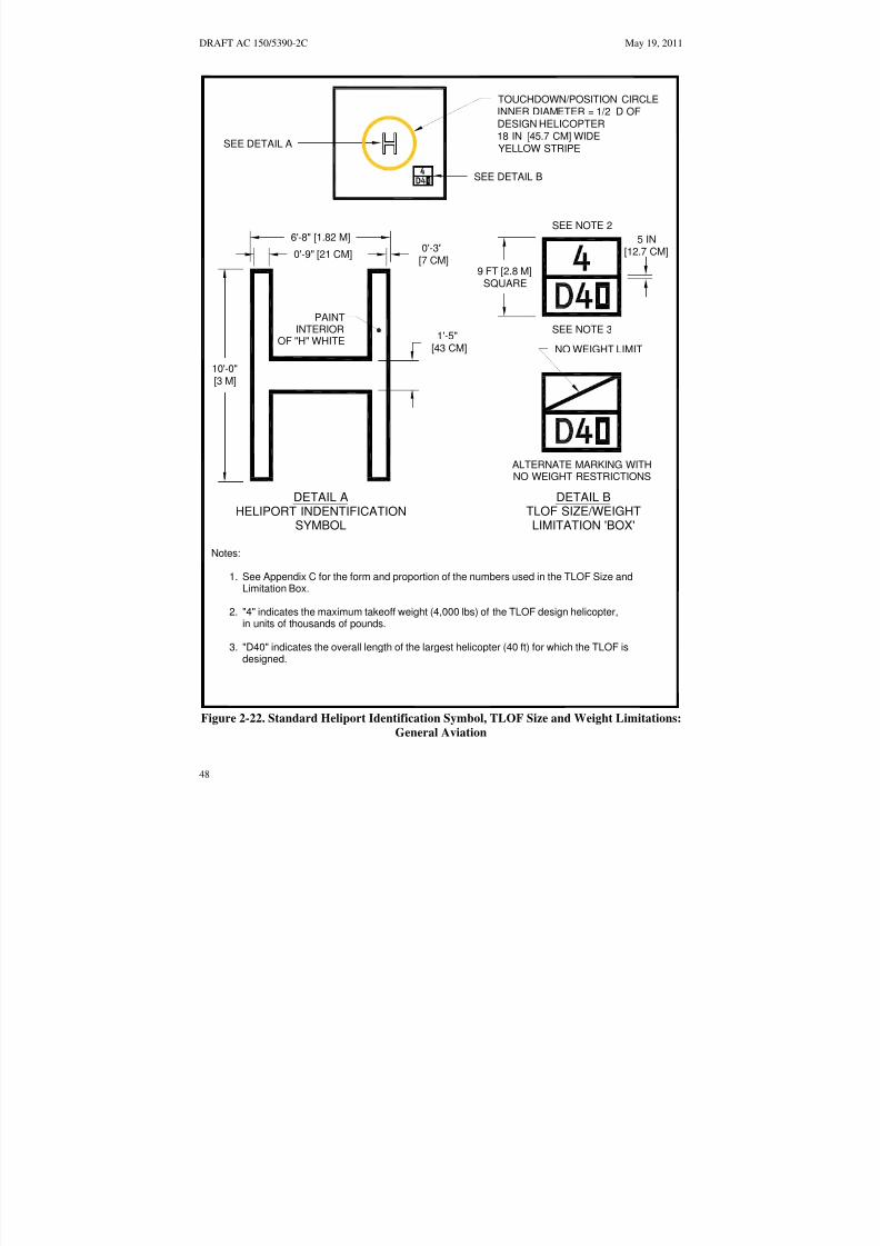
8/3/2019 draft_150_5390_2C
http://slidepdf.com/reader/full/draft15053902c 56/198
DRAFT AC 150/5390-2C May 19, 2011
ALTERNATE MARKING WITH
Notes:
See Appendix C for the form and proportion of the numbers used in the TLOF Size and
"4" indicates the maximum takeoff weight (4,000 lbs) of the TLOF design helicopter,
"D40" indicates the overall length of the largest helicopter (40 ft) for which the TLOF is
1.
2.
3.
DETAIL B
Limitation Box.
designed.
in units of thousands of pounds.
NO WEIGHT RESTRICTIONS
TLOF SIZE/WEIGHTLIMITATION 'BOX'
SEE DETAIL B
SEE DETAIL A
TOUCHDOWN/POSITION CIRCLEINNER DIAMETER = 1/2 D OFDESIGN HELICOPTER18 IN [45.7 CM] WIDEYELLOW STRIPE
NO WEIGHT LIMIT
DETAIL AHELIPORT INDENTIFICATION
SYMBOL
PAINT
OF "H" WHITEINTERIOR
0'-9" [21 CM]0'-3"
[7 CM]
6'-8" [1.82 M]
1'-5"[43 CM]
5 IN[12.7 CM]
10'-0"[3 M]
SEE NOTE 2
SEE NOTE 3
9 FT [2.8 M]SQUARE
Figure 2-22. Standard Heliport Identification Symbol, TLOF Size and Weight Limitations: General Aviation
48

8/3/2019 draft_150_5390_2C
http://slidepdf.com/reader/full/draft15053902c 57/198
May 19, 2011 DRAFT AC 150/5390-2C
Notes:
Expanded load bearing markings begin flush with TLOF edge markings and end1.
2. Expanded Load bearing markings are defined with 12 in [30 cm] wide black andwhite stripes on a 45° angle.
TLOF EDGE MARKING
FATO EDGE MARKING
at the edge of the LBA.
FLUSH FATO EDGE LIGHTSLBA
Figure 2-23. LBA Marking: General Aviation
49

8/3/2019 draft_150_5390_2C
http://slidepdf.com/reader/full/draft15053902c 58/198
ure 2-22
DRAFT AC 150/5390-2C May 19, 2011
DETAIL A FATO MARKING DETAIL
5 FT [1.5 M]5 FT [1.5 M] MIN6 FT [2 M] MAX
Notes:
The perimeter of the TLOF and FATO are marked.1.
2.
3.
PAINTED TLOF EDGE MARKING
FATO EDGE MARKING
APPROACH/DEPARTURE SURFACE
SAFETY AREA
SEE NOTES 3 & 4 AND DETAIL A
APPROACH/DEPARTURE SURFACE
SEE NOTE 2
The perimeter of a paved or hard surfaced TLOF is defined with a continuous12 in [30 cm] white line.
Paved FATO perimeters are defined with a 12 in [30 cm] wide dashed line per Detail A.
TDPCMARKING
4.
5. See Fig for " H", Touchdown/Position, Overall Length and Weight Limitation boxdimensions.
Unpaved FATO perimeters are defined with a flush in-ground marker per Detail A.
Figure 2-22
Figure 2-24. Paved TLOF/Paved FATO – Paved TLOF/ Unpaved FATO – Marking: General Aviation
50

8/3/2019 draft_150_5390_2C
http://slidepdf.com/reader/full/draft15053902c 59/198
May 19, 2011 DRAFT AC 150/5390-2C
APPROACH/DEPARTURE SURFACEIN GROUND FATO EDGE MARKING
SEE NOTE 3 AND DETAIL BUNPAVED TLOF EDGE MARKING TDPC
SEE NOTE 2 AND DETAIL A MARKING
UNPAVED FATO
SAFETY AREA
APPROACH/DEPARTURE SURFACE
0 FT [0 M] MIN5 FT [1.5 M] 6 IN [30 CM] MAX1FT [30 CM]
DETAIL A TLOF FLUSH IN-GROUND MARKING DETAIL
5 FT [1.5 M] MIN5 FT [1.5 M]
6 FT [2 M] MAX1 FT [30 CM]
DETAIL B FATO FLUSH IN-GROUND MARKING DETAIL
Notes:
1. The perimeter of the TLOF and FATO are marked.
2. An unpaved TLOF perimeter is defined with flush in-ground markers per Detail A.
3. An unpaved FATO perimeter is defined with flush in-ground markers per Detail B.
Figure 2-22 dimensions. 4. See Figure 2-22 for "H", Touchdown/Position, Overall Length and Weight Limitation box
Figure 2-25. Unpaved TLOF/Unpaved FATO – Marking:
General Aviation
51

8/3/2019 draft_150_5390_2C
http://slidepdf.com/reader/full/draft15053902c 60/198
DRAFT AC 150/5390-2C May 19, 2011
e. Flight Path Alignment Guidance Marking. An optional flight path alignment guidancemarking consists of one or more arrows to indicate the preferred approach/departure direction(s). It ismarked on the TLOF, FATO and/or safety area surface as shown in Figure 2-11 on page 32. The shaft of the arrow(s) is 18 in. (50 cm) in width and at least 10 feet (3 m) in length. The markings must be in acolor which provides good contrast against the background color of the surface on which they are marked.In the case of a flight path limited to a single approach direction or a single departure path, the arrow
marking is unidirectional. In the case of a heliport with only a bidirectional approach /takeoff flight pathavailable, the arrow marking is bidirectional.
f. Taxiway and Taxi Route Markings.
(1) Paved Taxiway Markings. The centerline of a paved taxiway is marked with a continuous 6inch (15 cm) yellow line. Both edges of the paved portion of the taxiway are marked with two continuous6- inch wide (15 cm) yellow lines spaced 6 inches (15 cm) apart. Figure 2-13 on page 34 illustratestaxiway centerline and edge markings.
(2) Unpaved Taxiway Markings. Edge markers are used to provide strong visual cues to pilots.Edge markers may be either raised or in-ground flush markers. They are longitudinally spaced at
approximately 15-foot (5 m) intervals on straight segments and at approximately 10-foot (3 m) intervalson curved segments. Figure 2-14 on page 35 and Figure 2-15 on page 36 illustrate taxiway edgemarkings.
(a) Raised-edge markers are blue, 4 inches (10 cm) in diameter, and 8 inches (20 cm) high,as illustrated in Figure 2-14 on page 35.
(b) In-ground, flush edge markers are yellow, 12 inches (30 cm) wide, and approximately 5feet (1.5 m) long.
(3) Raised Edge Markers in Grassy Areas. Raised edge markers are sometimes obscured bytall grass. The heliport operator should address this problem with a 12-inch diameter (30 cm) diameter
solid material disk around the pole supporting the raised marker.
(4) Taxiway to Parking Position Transition Requirements. For paved taxiways and parkingareas, taxiway centerline markings continue into parking positions and become the parking positioncenterlines.
g. Helicopter Parking Position Markings. Helicopter parking positions have the followingmarkings:
(1) Paved Parking Position Identifications. Parking position identifications (numbers or letters)are marked if there is more than one parking position. These markings are yellow characters 3 feet (0.9 m)high. (See Figure 2-21 on page 45 and Figure C–1 on page 187).
(2) Rotor Diameter Circle. A 6-inch-wide (15 cm), solid yellow line defines a circle of the rotordiameter of the largest helicopter that will park at that position. The RD is defined by the outside diameterof the circle. In paved areas, this is a painted line (see Figure 2-21 on page 45). In unpaved areas, this lineis defined by a series of flush markers, 6 inches (15 cm) in width, a maximum of 5 feet (1.5 m) in length,and with end-to-end spacing of approximately 5 feet (1.5 m).
(3) Touchdown/Positioning Circle (TDPC) Marking. An optional touchdown/positioningcircle marking provides guidance to allow a pilot to touch down in a specific position on paved surfaces.
52

8/3/2019 draft_150_5390_2C
http://slidepdf.com/reader/full/draft15053902c 61/198
May 19, 2011 DRAFT AC 150/5390-2C
When the pilot’s seat is over the marking, the undercarriage will be inside the load-bearing area, and allparts of the helicopter will be clear of any obstacle by a safe margin. A TDPC marking is a yellow circlewith an inner diameter of 0.5 D and a line width of 18 in (0.5 m). A TDPC marking is located in thecenter of a parking area. See Figure 2-21 on page 45 and Figure 2-24 on page 50. A TDPC marking isrecommended for “turn-around” parking areas.
(4) Maximum Length Marking. This marking on paved surfaces indicates the D of the largesthelicopter that the position is designed to accommodate (e.g., 49). This marking is in yellow characters atleast 3 feet (0.9 m) high. (See Figure 2-21 on page 45 and Figure C–1 on page 187.)
(5) Parking Position Weight Limit. If a paved parking position has a weight limitation, it isstated in units of 1,000 pounds as illustrated in Figure 2-21 on page 45. (A 4 indicates a weight-carryingcapability of up to 4,000 pounds. Metric equivalents are not be used for this purpose.) This markingconsists of yellow characters 3 feet (0.9 m) high. A bar may be placed under the number to minimize thepossibility of being misread. (See Figure 2-21 on page 45, Figure 2-24 on page 49, and Figure C–1 onpage 187.
(6) Shoulder Line Markings. Optional shoulder line markings are used for paved parking areas
(Figure 2-21 on page 45) to ensure safe rotor clearance. A 6-inch-wide (15 cm) solid yellow shoulder line,perpendicular to the centerline and extending to the RD marking, is located so it is under the pilot’sshoulder such that the main rotor of the largest helicopter for which the position is designed will beentirely within the rotor diameter parking circle (see Figure 2-21 on page 45). Use 0.25D from the centerof parking area to define the location of shoulder line. A shoulder line marking is recommended for “taxithrough” and “back-out” parking areas.
h. Walkways. Figure 2-21 on page 45 illustrates one marking scheme.
i. Closed Heliport. All markings of a permanently closed heliport, FATO, or TLOF should beobliterated. If it is impractical to obliterate markings, a yellow “X” should be placed over the “H” asillustrated in Figure 2-26 on page 54. The yellow “X” should be large enough to ensure early pilot
recognition that the heliport is closed. The wind cone(s) and other visual indications of an active heliportshould also be removed.
j. Marking Sizes.See Appendix C on page 187 for guidance on the proportions of paintednumbers.
53

8/3/2019 draft_150_5390_2C
http://slidepdf.com/reader/full/draft15053902c 62/198

8/3/2019 draft_150_5390_2C
http://slidepdf.com/reader/full/draft15053902c 63/198
May 19, 2011 DRAFT AC 150/5390-2C
on the outer edge of the safety net also provides better visual cues to pilots at a distance from the heliportsince it outlines a larger area. The raised lights must not penetrate a horizontal plane at the TLOFelevation by more than 2 inches (5 cm).
SAFETY NET
B
NOT LESS THAN 5 FT [1.5 M]
NOT MORE THAN2 IN [5 CM]
12 IN [30 CM]
AC
(SURROUNDING
THE TLOF or LBA)
Three possible locations for TLOF/LBA edge lighting:
Flush edge fixtures
Omni-directional light, mounted off TLOF/LBA edge
Omni-directional light, mounted off outer edge of safety net (preferred location
in snow areas)
A
B
C
FALL PROTECTION:
RECOMMENDED IFABOVE 30 IN [0.8 M]
REQUIRED IFABOVE 4 FT [1.2 M]
Figure 2-27. Elevated TLOF/LBA – Perimeter Lighting: General Aviation
(2) PPR facilities. Flush lights are recommended for PPR heliports, but raised omnidirectionallights may be used if only the TLOF is load bearing. The raised lights should be located outside andwithin 10 feet (3m) of the edge of the TLOF and should not penetrate a horizontal plane at the TLOFelevation by more than 2 inches (5 cm). When the load-bearing area (LBA) is larger than the TLOF,perimeter lights may be mounted on the outer edge of the LBA or the inner or outer edge of the safety net.
b. Load-bearing FATO Perimeter Lights. Green lights meeting the requirements of EB 87 definethe perimeter of a load bearing FATO. The FATO perimeter is not lighted if any portion of the FATO isnot a load-bearing surface. A minimum of four flush or raised light fixtures is required per side of asquare or rectangular FATO, except at PPR facilities, for which the minimum recommended number isthree. A light is located at each corner, with additional lights uniformly spaced between the corner lights.It is recommended each side comprise an odd number of lights, thereby including lights along thecenterline of the approach. To define a circular FATO, an even number of lights, with a minimum of eight, are uniformly spaced. The maximum spacing of lights is 25 feet (7.6 m). Flush lights are locatedwithin 1 foot (30 cm) (inside or outside) of the FATO perimeter (See Figure 2-28 on page 57). In areas
55

8/3/2019 draft_150_5390_2C
http://slidepdf.com/reader/full/draft15053902c 64/198
DRAFT AC 150/5390-2C May 19, 2011
where it snows, the outside edge is the preferred location, as lights on the inside edge of the FATO areprone to breakage during snow removal. A square or rectangular pattern of FATO perimeter lights arerecommended even if the TLOF is circular. At a distance during nighttime operations, a square orrectangular pattern of FATO perimeter lights provides the pilot with better visual cues than a circularpattern. In the case of an elevated FATO with a safety net, the perimeter lights are mounted in a similarmanner as discussed in paragraph 215.a(1) above. If raised FATO perimeter lights are used, they should
be no more than 8 inches (20 cm) high, and located 10 feet (3 m) from the FATO perimeter. (See Figure2-29 on page 58.) When a heliport on an airport is sited near a taxiway, there may be a concern that thegreen taxiway centerline lights could be confused with the FATO perimeter lights. In such cases, yellowlights may be used as an alternative color for marking the FATO.
c. Floodlights. If ambient light does not adequately illuminate markings for night operations,floodlights should be used to illuminate the TLOF, the FATO, and/or the parking area. To eliminate theneed for tall poles, these floodlights may be mounted on adjacent buildings. Care should be taken,however, to place floodlights clear of the TLOF, the FATO, the safety area, and the approach/departuresurfaces, and transitional surfaces. Care should be taken to ensure that floodlights and their associatedhardware do not constitute an obstruction hazard. Floodlights should be aimed down and provideadequate illumination on the surface. Floodlights that might interfere with pilot vision during takeoff and
landings should be capable of being turned off by pilot control or at pilot request.
d. Landing Direction Lights. Landing direction lights are an optional feature to be installed when itis necessary to provide directional guidance. Landing direction lights are a configuration of five white,omnidirectional lights meeting the standards of EB 87, on the centerline of the preferredapproach/departure path. These lights are spaced at 15-foot (5 m) intervals beginning at a point not lessthan 20 feet (6 m) and not more than 60 feet (18 m) from the TLOF perimeter and extending outward inthe direction of the preferred approach/departure path, as illustrated in Figure 2-30 on page 59.
e. Flight Path Alignment Lights. Flight path alignment lights meeting the requirements of FAAEngineering Brief 87 are optional. They are placed in a straight line along the direction of approachand/or departure flight paths. The lights may extend across the TLOF, FATO, safety area or any suitable
surface in the immediate vicinity of the FATO or safety area. Three or more white lights are spaced at 5feet (1.5 m) to 10 feet (3.0 m). (See Figure 2-11 on page 32.)
f. Taxiway and Taxi Route Lighting.
(1) Taxiway Centerline Lights. Taxiway centerlines are defined with flush bidirectional greenlights meeting the standards of AC 150/5345-46 for type L-852A (straight segments) or L-852B (curvedsegments). These lights are spaced at maximum 50-foot (15 m) longitudinal intervals on straight segmentsand at maximum 25-foot (7.5 m) intervals on curved segments, with a minimum of four lights needed todefine the curve. Taxiway centerline lights may be uniformly offset no more than two feet to easepainting the taxiway centerline. Green retroreflective markers meeting requirements for type II markers inAC 150/5345-39, Specification for L-853, Runway and Taxiway Retroreflective Markers, may be used in
lieu of the L-852A or L-852B lighting fixtures.
(2) Taxiway Edge Lights. Omnidirectional blue lights are used to light the edges of a taxiway.Blue retroreflective markers may be used to identify the edges of the taxiway in lieu of lights. Whenretroreflective markers are used, they must be no more than 8 inches (20 cm) tall.
(a) Straight Segments. Lights are spaced at 50 feet (15.2 m) longitudinal intervals onstraight segments.
56

8/3/2019 draft_150_5390_2C
http://slidepdf.com/reader/full/draft15053902c 65/198
May 19, 2011 DRAFT AC 150/5390-2C
5 APPROACH LIGHTS (OPTIONAL)
LIGHTED WIND CONE Figure 2-30SEE FIGURE 2-30 FOR DETAILS
PREFERRED APPROACH CL
FLUSH FATO EDGE LIGHTS
FLUSH TLOF EDGE LIGHTS
1 FT [30 CM]
FLUSH IN-PAVEMENT LIGHT DETAIL
Notes:
1. Flush FATO and TLOF perimeter lights may be installed inside or outside within 1 ft [30 cm] of the FATO and TLOF respective perimeters.
2. Overall length and weight limitation box is omitted for clarity.
Figure 2-28. TLOF/FATO Flush Perimeter Lighting:
General Aviation
57

8/3/2019 draft_150_5390_2C
http://slidepdf.com/reader/full/draft15053902c 66/198
DRAFT AC 150/5390-2C May 19, 2011
5 LANDING LIGHTS (OPTIONAL)
SEE FIGURE 2-23 FOR DETAILSFigure 2-30
LIGHTED WIND CONE
PREFERRED APPROACH CL
SEE NOTE 2
RAISED FATO OMNI-DIRECTIONALLIGHTS
FLUSH TLOF EDGE LIGHTS
Notes:
1. Flush FATO and TLOF perimeter lights may be installed inside or outside within 1 ft [30 cm] of the FATO and TLOF respective perimeters.
2. Raised FATO lights may be installed 10 ft [3 m] outside the FATO perimeter.
3. Overall length and weight limitation box is omitted for clarity.
Figure 2-29. TLOF Flush and FATO Raised Perimeter Lighting:
General Aviation
58

8/3/2019 draft_150_5390_2C
http://slidepdf.com/reader/full/draft15053902c 67/198
May 19, 2011 DRAFT AC 150/5390-2C
FATO
TLOF
NOT LESS THAN20 FT [6 M]
NOR MORE THAN
60 FT [18 M]
4 EQUAL SPACES
@ 15 FT [4.6 M]= 60 FT [18.4 M]
OMNI-DIRECTIONAL WHITE LIGHTS
LEGEND
Note: Not drawn to scale
Figure 2-30. Landing Direction Lights: General Aviation
59

8/3/2019 draft_150_5390_2C
http://slidepdf.com/reader/full/draft15053902c 68/198
DRAFT AC 150/5390-2C May 19, 2011
(b) Curved Segments. Curved taxiway edges require shorter spacing of edge lights. Thespacing is determined based on the radius of the curve. The applicable spacing for curves is shown inFigure 17 of AC 150/5340-30, Design and Installation Detail for Airport Visual Aids. The taxiway edgelights are uniformly spaced. Curved edges of more than 30 degrees from point of tangency (PT) of thetaxiway section to PT of the intersecting surface must have at least three edge lights. For radii not listed inFigure 17 determine spacing by linear interpolation.
(c) Paved Taxiways. Flush lights must meet the standards of AC 150/5345-46 for typeL-852T .
(d) Unpaved Taxiways. Raised lights must meet the standards of AC 150/5345-46 for typeL-861T. The lateral spacing for the lights or reflectors is equal to the RD of the design helicopter, but notmore than 35 feet.
g. Heliport Identification Beacon. A heliport identification beacon is optional equipment. It shouldbe installed when it is needed to aid the pilot in visually locating the heliport. When installed, the beacon,flashing white/green/yellow at the rate of 30 to 45 flashes per minute, is located on or close to theheliport. Guidance on heliport beacons is found in AC 150/5345-12, Specification for Airport and
Heliport Beacon. It is permissible for the beacon to be pilot controllable such that it is “on” only whenrequired.
216. MARKING AND LIGHTING OF DIFFICULT-TO-SEE OBJECTS. Unmarked wires,antennas, poles, cell towers, and similar objects are often difficult to see, even in the best daylightweather, in time for a pilot to successfully take evasive action. While pilots can avoid such objects duringen route operations by flying well above them, approaches and departures require operations near theground where obstacles may be a factor. This paragraph discusses the marking and lighting of objectsnear, but outside and below the approach/departure surface. Guidance on marking and lighting objects iscontained in AC 70/7460-1, Obstruction Marking and Lighting.
a. Airspace. If difficult-to-see objects penetrate the object identification surfaces illustrated in
Figure 2-31 on page 61, these objects must be marked to make them more conspicuous. If operations areconducted at a heliport between dusk and dawn, these difficult-to-see objects must be lighted. The objectidentification surfaces in Figure 2-31 on page 61 are described as follows:
(1) In all directions from the safety area except under the approach/departure paths, the objectidentification surface starts at the safety area perimeter and extends out horizontally for a distance of 100feet (30.5 m).
(2) Under the approach/departure surface, the object identification surface starts from the outsideedge of the FATO and extends horizontally out for a distance of 800 feet (244 m). From this point, theobject identification surface extends out for an additional distance of 3,200 feet (975 m) while rising onan 8:1 slope (8 units horizontal in 1 unit vertical). From the point 800 feet (244 m) from the FATO
perimeter, the object identification surface is 100 feet (30.5 m) beneath the approach/departure surface.
(3) The width of this object identification surface under the approach/departure surface increasesas a function of distance from the safety area. From the safety area perimeter, the object identificationsurface extends laterally to a point 100 feet (30.5 m) outside the safety area perimeter. At the upper end of the surface, the object identification surface extends laterally 200 feet (61 m) on either side of theapproach/departure path.
60

8/3/2019 draft_150_5390_2C
http://slidepdf.com/reader/full/draft15053902c 69/198
May 19, 2011 DRAFT AC 150/5390-2C
( 8 : 1 S L O
P E )APPROACH/DEPARTURE SURFACE
( 8 : 1 S L O
P E )
OBJECT IDENTIFICATION SURFACE
FATO
400 FT[122 M]
100 FT[30 M]
500 FT[152 M]
3,200 FT [975 M]
500 FT[152 M]
100 FT [30 M]FROM EDGE
OF SAFETY AREA
100 FT [30 M] FROM EDGE OF SAFETY AREA
100 FT [30 M] R200 FT[61 M]
Note: Not drawn to scale
Figure 2-31. Airspace Where Marking and Lighting are Recommended: General Aviation
b. Shielding of Objects. If there are a number of objects close together, it may not be necessary tomark all of them if they are shielded. To meet the shielding guidelines an object must be shielded by
existing structures of a permanent and substantial character or by natural terrain or topographic features of equal or greater height, and must be located in the congested area of a city, town, or settlement where it isevident beyond all reasonable doubt that the structure so shielded will not adversely affect safety in airnavigation. Additional guidance on this topic may be found in 14 CFR part 77.9, Construction or
alteration requiring notice.
c. Equipment/Object Marking. Heliport maintenance and servicing equipment, as well as otherobjects used in the airside operational areas, should be made conspicuous with paint, reflective paint,
61

8/3/2019 draft_150_5390_2C
http://slidepdf.com/reader/full/draft15053902c 70/198
DRAFT AC 150/5390-2C May 19, 2011
reflective tape, or other reflective markings. Reference AC 150/5210-5, Painting, Marking, and Lighting
of Vehicles Used on an Airport .
217. SAFETY CONSIDERATIONS. Some safety enhancements to be considered in the design of aheliport are discussed below. Other areas such as the effects of rotor downwash may need to be addressedbased on site conditions and the design helicopter.
a. Security. The operational areas of a heliport must be kept clear of people, animals, and vehicles.The method used to control access depends upon the helicopter location and types of potential intruders.
(1) Safety Barrier. At ground-level general aviation heliports, one control method is to erect asafety barrier around the helicopter operational areas. This barrier may take the form of a fence, wall, orhedge. It must be no closer to the operating areas than the outer perimeter of the safety area. Barriers mustnot penetrate any approach /departure (primary or transitional) surface. Thus, in the vicinity of theapproach/departure paths, the barrier may need to be well outside the outer perimeter of the safety area.
(2) Any barrier must be high enough to present a positive deterrent to persons inadvertentlyentering an operational area and yet low enough to be non-hazardous to helicopter operations.
(3) Access to airside areas must be controlled in a manner commensurate with the barrier (e.g. afence should contain a locked gate). Access points should display a cautionary sign similar to thatillustrated in Figure 2-32 on page 63.
b. Rescue and Fire-Fighting Services. Heliports must meet State and local rescue and fire-fightingregulations. A fire hose cabinet or extinguisher must be provided at each access gate/door and eachfueling location. At elevated TLOFs, fire hose cabinets, fire extinguishers, and other fire-fightingequipment must be located adjacent to, but below the level of, the TLOF. Information is available inNFPA 418, Standards for Heliports, and NFPA 403, Standard for Aircraft Rescue and Fire-Fighting
Services at Airports. NFPA standards are available at National Fire Protection Association web site athttp://www.nfpa.org.
c. Communications. A Common Traffic Advisory Frequency (CTAF) radio may be used toprovide arriving helicopters with heliport and traffic advisory information but may not be used to controlair traffic. The Federal Communications Commission (FCC) should be contacted for information onCTAF licensing.
d. Weather Information. An automated weather observing system (AWOS) measures andautomatically broadcasts current weather conditions at the heliport site. When an AWOS is installed, itmust be located at least 100 feet (30 m) and not more than 700 feet (213 m) from the TLOF. Locate theAWOS so its instruments will not be affected by rotor wash from helicopter operations. Guidance onAWOS systems is found in AC 150/5220-16, Automated Weather Observing Systems (AWOS) for Non-
Federal Applications, and FAA Order 6560.20, Siting Criteria for Automated Weather Observing Systems
(AWOS).
e. Winter Operations. Swirling snow raised by a helicopter’s rotor wash can cause the pilot to losesight of the intended landing point and/or hide objects that need to be avoided. The TLOF, the FATO, andas much of the safety area as practical should be kept free of snow. Heliport design should take intoaccount the methods and equipment to be used for snow removal. The heliport design should allow thesnow to be removed sufficiently so the snow will not present an obstruction hazard to either the tail rotoror the main rotor. Guidance on winter operations is found in AC 150/5200-30, Airport Winter Safety and
Operations.
62

8/3/2019 draft_150_5390_2C
http://slidepdf.com/reader/full/draft15053902c 71/198
May 19, 2011 DRAFT AC 150/5390-2C
CAUTIONHELICOPTER LANDING
AUTHORIZEDPERSONNEL
ONLY
AREA
SAFETY
INSTRUCTIONS
AVOID FRONT AND REARAREA OF HELICOPTER
STAY CLEAROF THE
TAIL ROTOR
APPROACH AND LEAVE HELICOPTER FROM THE SIDEIN A CROUCHED MANNER WHEN ROTORS ARE TURNING
AVOID FRONT AND REARAREA OF HELICOPTER
Figure 2-32. Caution Sign: General Aviation
63

8/3/2019 draft_150_5390_2C
http://slidepdf.com/reader/full/draft15053902c 72/198
L O W E R L I M I T O
F T H E O N- C O
U R S E S I G NA L
OBS TACLE CLEAR
ANCE REFERENC
E LINE
L O W E R L I M I T O
F T H E O N- C O
U R S E S I G NA L
OBS TACLE CLEAR
ANCE REFERENC
E LINE
DRAFT AC 150/5390-2C May 19, 2011
OBSTACLE CLEARANCEPLANE
10°
COURSE CENTERLINE
10°
CRITICALOBJECT
VISUAL GLIDESLOPEINDICATOR (VGSI)
1°MINIMUM CLEARANCE
VISUAL GLIDESLOPEINDICATOR (VGSI)
VARIABLE SEE DETAIL BELOW
PILOT'S EYES
VISUAL GLIDESLOPEINDICATOR (VGSI)
3 FT TO 8 FT
[1 M TO 2.4 M]
Note: Not drawn to scale
Figure 2-33. Visual Glideslope Indicator Siting and Clearance Criteria:
General Aviation
64

8/3/2019 draft_150_5390_2C
http://slidepdf.com/reader/full/draft15053902c 73/198
May 19, 2011 DRAFT AC 150/5390-2C
218. VISUAL GLIDESLOPE INDICATORS (VGSI). A visual glideslope indicator (VGSI)provides pilots with visual vertical course and descent cues. The lowest on-course visual signal mustprovide a minimum of 1 degree of clearance over any object that lies within 10 degrees of the approachcourse centerline.
a. Siting. The optimum location of a VGSI is on the extended centerline of the approach path at a
distance that brings the helicopter to a hover with the undercarriage between 3 and 8 feet (0.9 to 2.5 m)above the TLOF. Figure 2-33 on above illustrates VGSI clearance criteria. This will require estimatingthe vertical distance from the undercarriage to the pilot’s eye.
b. Control of the VGSI. It is permissible for the VGSI to be pilot controllable such that it is “on”only when required.
c. VGSI Needed. A VGSI is an optional feature. However, a VGSI should be provided if one ormore of the following conditions exist, especially at night:
(1) Obstacle clearance, noise abatement, or traffic control procedures require a particular slope tobe flown.
(2) The environment of the heliport provides few visual surface cues.
d. Additional Guidance. AC 150/5345-52, Generic Visual Glideslope Indicators (GVGI), and AC150/5345-28, Precision Approach Path Indicator (PAPI) Systems, provide additional guidance.
219. TERMINAL FACILITIES. The heliport terminal requires curbside access for passengers usingprivate autos, taxicabs, and public transit vehicles. Public waiting areas need the usual amenities, and acounter for rental car services may be desirable. Passenger auto parking areas should accommodatecurrent requirements and have the capability of being expanded to meet future requirements. Readilyavailable public transportation may reduce the requirement for employee and service personnel autoparking spaces. The heliport terminal building or sheltered waiting area should be attractive and
functional. AC 150/5360-9, Planning and Design of Airport Terminal Facilities at Non-Hub Locations,contains guidance on designing terminal facilities. At PPR heliports, the number of people using thefacility may be so small that there is no need for a terminal building. In addition, the other facilities andamenities needed may be minimal.
220. ZONING AND COMPATIBLE LAND USE. Where state and local statutes permit, the GAheliport operator is encouraged to promote the adoption of the following zoning measures to ensure thatthe heliport will continue to be available and to protect the investment in the facility.
a. Zoning to Limit Building/Object Heights. General guidance on drafting an ordinance thatwould limit building and object heights is contained in AC 150/5190-4, A Model Zoning Ordinance to
Limit Height of Objects Around Airports. The ordinance should substitute the heliport surfaces for theairport surfaces in the model ordinance.
b. Zoning for Compatible Land Use. A zoning ordinance may be enacted, or an existing ordinancemodified, to control the use of property within the Heliport Protection Zone. The ordinance should restrictactivities to those that are compatible with helicopter operations. See paragraph 210 on page 31.
c. Air Rights and Property Easements are options that may be used to prevent the encroachmentof obstacles in the vicinity of a heliport.
65

8/3/2019 draft_150_5390_2C
http://slidepdf.com/reader/full/draft15053902c 74/198
DRAFT AC 150/5390-2C May 19, 2011
Intentionally left blank
66

8/3/2019 draft_150_5390_2C
http://slidepdf.com/reader/full/draft15053902c 75/198
May 19, 2011 DRAFT AC 150/5390-2C
CHAPTER 3. TRANSPORT HELIPORTS 301. GENERAL. A transport heliport is intended to accommodate air carrier operators providingscheduled or unscheduled service with large helicopters. This chapter contains standards andrecommendations for designing a transport heliport. The design recommendations given in this chapter
are based on the assumption that there will never be more than one helicopter within the final approachand takeoff area (FATO) and the associated safety area. If there is a need for more than one touchdownand lift-off area (TLOF) at a heliport, each TLOF must be located within its own FATO and within itsown safety area. Figure 3-1 on page 68 illustrates a typical transport heliport.
302. ACCESS BY INDIVIDUALS WITH DISABILITIES. Heliports operated by public entitiesand those receiving Federal financial assistance must meet accessibility requirements. See paragraph 112on page 12.
303. HELIPORT SITE SELECTION.
a. Long Term Planning. Public agencies and others planning to develop a transport heliport
should consider the possible future need for instrument operations and future expansion.
b. Property Requirements. The property needed for a transport heliport depends upon thevolume and types of users and the scope of amenities provided. Property requirements for helicopteroperators and for passenger amenities frequently exceed that required for “airside” purposes.
c. Turbulence. Air flowing around and over buildings, stands of trees, terrain irregularities, etc.can create turbulence on ground-level and roof-top heliports that may affect helicopter operations. Wherethe FATO is located near the edge and top of a building or structure, or within the influence of turbulentwakes from other buildings or structures, the turbulence and airflow characteristics in the vicinity of, andacross the surface of the FATO should be assessed to determine if an air-gap between the roof, roof parapet or supporting structure, and/or some other turbulence mitigating design measure is necessary. See
FAA Technical Report FAA/RD-84/25, Evaluating Wind Flow Around Buildings on Heliport Placement addresses the wind’s effect on helicopter operations. The following actions may be taken in selecting asite to minimize the effects of turbulence.
(1) Ground-Level Heliports. Helicopter operations from sites immediately adjacent tobuildings, trees, and other large objects are subjected to air turbulence effects caused by such features.Therefore, locate the landing and takeoff area away from such objects in order to minimize air turbulencein the vicinity of the FATO and the approach/departure paths.
(2) Elevated Heliports. Establishing a 6 foot (1.8 m) or more air gap above the level of theroof will generally minimize the turbulent effect of air flowing over the roof edge. If an air gap or someother turbulence mitigating design measure is warranted but not practical, operational limitations mayneed to be considered under certain wind conditions. If an air gap is included in the design it should bekept free at all times of significant objects that would obstruct the airflow
67

8/3/2019 draft_150_5390_2C
http://slidepdf.com/reader/full/draft15053902c 76/198
DRAFT AC 150/5390-2C May 19, 2011
IN-GROUND FATOMARKING
RECTANGULAR FATO
APPROACH/DEPARTURE
SURFACE
PARKINGAPRON
APPROACH/DEPARTURESURFACE
LIGHTEDTLOF MARKINGWIND CONE
SAFETY AREARECTANGULAR TLOF
Notes:
1. The wind cone should be located so that it will not interfere with the approach/departure pathor transitional surface.2. TLOF size and weight limitation box omitted for clarity.
Figure 3-1. A Typical Transport Heliport:
Transport
68
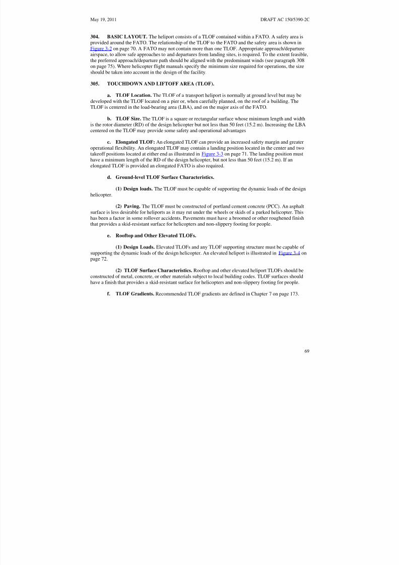
8/3/2019 draft_150_5390_2C
http://slidepdf.com/reader/full/draft15053902c 77/198
May 19, 2011 DRAFT AC 150/5390-2C
304. BASIC LAYOUT. The heliport consists of a TLOF contained within a FATO. A safety area isprovided around the FATO. The relationship of the TLOF to the FATO and the safety area is shown inFigure 3-2 on page 70. A FATO may not contain more than one TLOF. Appropriate approach/departureairspace, to allow safe approaches to and departures from landing sites, is required. To the extent feasible,the preferred approach/departure path should be aligned with the predominant winds (see paragraph 308on page 75). Where helicopter flight manuals specify the minimum size required for operations, the size
should be taken into account in the design of the facility.
305. TOUCHDOWN AND LIFTOFF AREA (TLOF).
a. TLOF Location. The TLOF of a transport heliport is normally at ground level but may bedeveloped with the TLOF located on a pier or, when carefully planned, on the roof of a building. TheTLOF is centered in the load-bearing area (LBA), and on the major axis of the FATO.
b. TLOF Size. The TLOF is a square or rectangular surface whose minimum length and widthis the rotor diameter (RD) of the design helicopter but not less than 50 feet (15.2 m). Increasing the LBAcentered on the TLOF may provide some safety and operational advantages
c. Elongated TLOF: An elongated TLOF can provide an increased safety margin and greateroperational flexibility. An elongated TLOF may contain a landing position located in the center and twotakeoff positions located at either end as illustrated in Figure 3-3 on page 71. The landing position musthave a minimum length of the RD of the design helicopter, but not less than 50 feet (15.2 m). If anelongated TLOF is provided an elongated FATO is also required.
d. Ground-level TLOF Surface Characteristics.
(1) Design loads. The TLOF must be capable of supporting the dynamic loads of the designhelicopter.
(2) Paving. The TLOF must be constructed of portland cement concrete (PCC). An asphalt
surface is less desirable for heliports as it may rut under the wheels or skids of a parked helicopter. Thishas been a factor in some rollover accidents. Pavements must have a broomed or other roughened finishthat provides a skid-resistant surface for helicopters and non-slippery footing for people.
e. Rooftop and Other Elevated TLOFs.
(1) Design Loads. Elevated TLOFs and any TLOF supporting structure must be capable of supporting the dynamic loads of the design helicopter. An elevated heliport is illustrated in Figure 3-4 onpage 72.
(2) TLOF Surface Characteristics. Rooftop and other elevated heliport TLOFs should beconstructed of metal, concrete, or other materials subject to local building codes. TLOF surfaces shouldhave a finish that provides a skid-resistant surface for helicopters and non-slippery footing for people.
f. TLOF Gradients. Recommended TLOF gradients are defined in Chapter 7 on page 173.
69
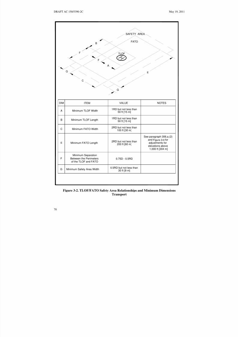
8/3/2019 draft_150_5390_2C
http://slidepdf.com/reader/full/draft15053902c 78/198
igure 3 4
DRAFT AC 150/5390-2C May 19, 2011
0.5RD but not less than
2RD but not less than100 ft [30 m]
F
G
TLOF
FATO
SAFETY AREA
B
F
DIM
B
C
E
F
ITEM VALUE
G
0.75D - 0.5RD
NOTES
2RD but not less than200 ft [60 m]
A1RD but not less than
50 ft [15 m]
G E
C
and f
30 ft [9 m]
See paragraph 306.a.(2)- for
1,000 ft [304 m]
adjustments forelevations above
Minimum TLOF Width
Minimum TLOF Length
Minimum FATO Width
Minimum FATO Length
Minimum Safety Area Width
Minimum Separation
Between the Perimetersof the TLOF and FATO
1RD but not less than50 ft [15 m]
Figure 3-4
Figure 3-2. TLOF/FATO Safety Area Relationships and Minimum Dimensions
Transport
70
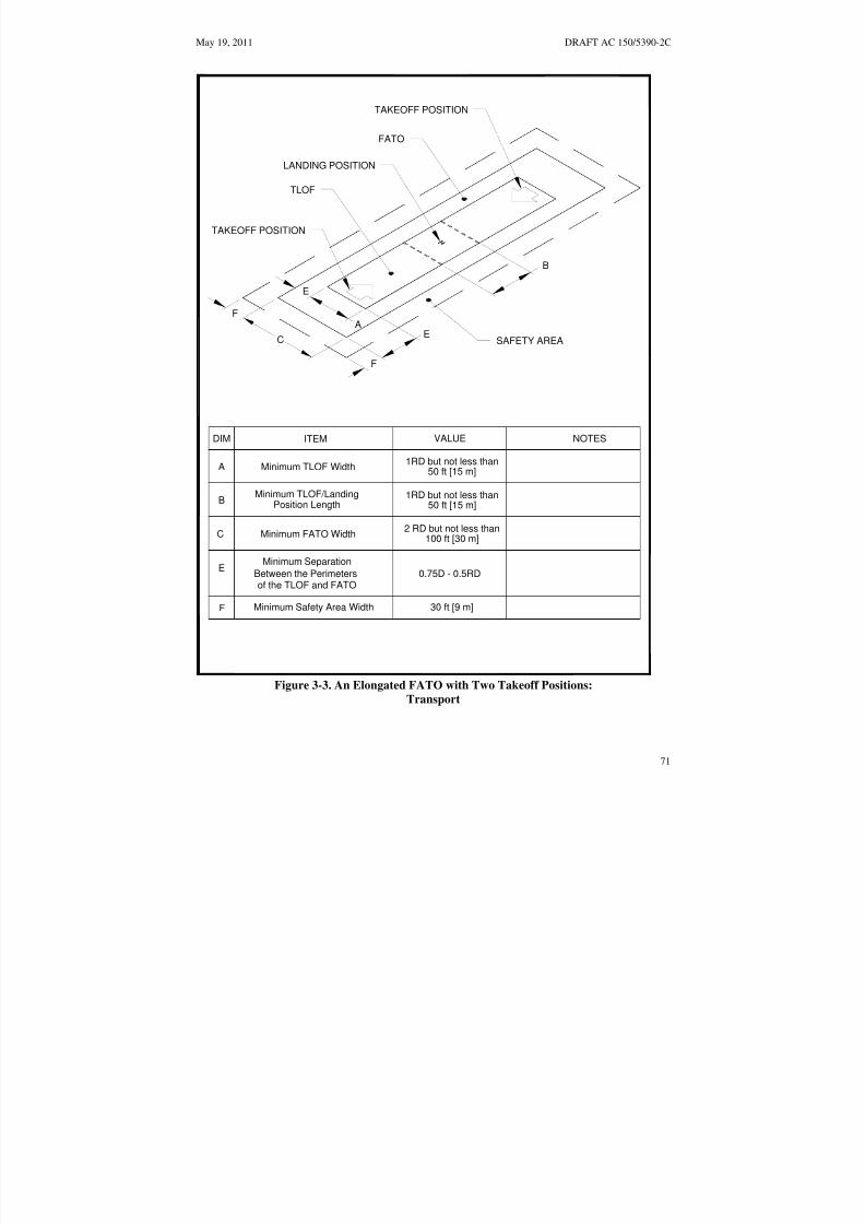
8/3/2019 draft_150_5390_2C
http://slidepdf.com/reader/full/draft15053902c 79/198
May 19, 2011 DRAFT AC 150/5390-2C
A
B
C
E
F
E
F
TAKEOFF POSITION
TAKEOFF POSITION
FATO
LANDING POSITION
TLOF
SAFETY AREA
DIM ITEM VALUE NOTES
A Minimum TLOF Width 1RD but not less than50 ft [15 m]
B Position LengthMinimum TLOF/Landing 1RD but not less than
50 ft [15 m]
C Minimum FATO Width2 RD but not less than
100 ft [30 m]
EMinimum Separation
Between the Perimetersof the TLOF and FATO
0.75D - 0.5RD
F Minimum Safety Area Width 30 ft [9 m]
Figure 3-3. An Elongated FATO with Two Takeoff Positions:
Transport
71

8/3/2019 draft_150_5390_2C
http://slidepdf.com/reader/full/draft15053902c 80/198
DRAFT AC 150/5390-2C May 19, 2011
L I G H T E D W I N D C O N E
T L O F
5 F T [ 1 . 5 M ] W
I D E S A F E T Y N E T
R A I S E D
F A T O
R A M P
S A F E T Y A R E A
H E L I P O R T
B E A C O N
F L U S H F A T O
L I G H T I N G
C A U T I O N
H E L I C O P T E R L A N D I N G
A R E A
S A F E T Y
A V O I D
R E A R
A R E A O F
H E L I C O P T E R
A V O I D
R E A R
A R E A O F
S T A Y C L E A R
O F T H E
H E L I C O P T E R
T A I L
R O T O R
A P P R O
A C H A N D L E A V E H E L I C O P T E R
I N A C R O U C H E D M A N N E R
W H E N
R O T O R S A R E T U R N I N G
N o t e s :
I N S T R U C T I O N S
A U T H O R
I Z E D
1 . S e e F i g u r e
3 - 2 2 f o r d e t a i l e d v i e w s o f t h e s a f e t y
F i g u r e
2 - 2 3
P E R S O N
N E L
n e t a n d l i g h t i n g .
O N L Y
2 . T L O F s i z e
a n d w e i g h t l i m i t a t i o n b o x i s n o t
s h o w n f o r c l a r i t y .
P o s t a t P e r s o n n e l E n t r a n c e
Figure 3-4. Elevated Heliport: Transport
72

8/3/2019 draft_150_5390_2C
http://slidepdf.com/reader/full/draft15053902c 81/198
May 19, 2011 DRAFT AC 150/5390-2C
306. FINAL APPROACH AND TAKEOFF AREA (FATO). A transport heliport must have at leastone FATO. The FATO must contain a TLOF within its borders at which arriving helicopters terminatetheir approach, and from which departing helicopters take off.
a. FATO Size. FATOs are rectangular surfaces with the long axis aligned with the preferredflight path. See Figure 3-2 on page 70.
(1) FATO Width. The minimum width of a FATO is at least 2.0 times the RD of the designhelicopter but not less than 100 feet (30.5 m).
(2) FATO Length. The minimum length of the FATO is 2.0 times the RD of the designhelicopter but not less than 200 feet (61 m). At elevations well above sea level, a longer FATO is requiredto provide an increased safety margin and greater operational flexibility. The additional FATO length thatmust be used is depicted in Figure 3-5 below.
300
200
100
00 1 2 3 4 5 6
0
90
60
30
A D D
I T I O N T O F A T O L E N G T H I N F E E T
A D D I T
I O N T O F A T O L E N G T H I N M E T E R
S
SITE ELEVATION (IN THOUSANDS OF FEET)
Example: 80 feet is added to the basic FATO length for a site elevation of 3,200 feet.
Figure 3-5. Additional FATO Length for Heliports at Higher Elevations:
Transport
(3) The minimum distance between the TLOF perimeter and the FATO perimeter is thedistance 0.75D - 0.5RD, where D and RD are of the design helicopter.
b. FATO Surface Characteristics.
(1) The entire FATO must be capable of supporting the dynamic loads of the designhelicopter.
73

8/3/2019 draft_150_5390_2C
http://slidepdf.com/reader/full/draft15053902c 82/198
DRAFT AC 150/5390-2C May 19, 2011
(2) If it is unpaved, the FATO surface must be treated to prevent loose stones and any otherflying debris caused by rotor wash.
(3) The portion of the FATO abutting the TLOF must be contiguous with the TLOF and theadjoining edges must be at the same elevation.
c. Rooftop and Other Elevated FATOs.
(1) Design Loads. Elevated FATOs and any FATO supporting structure must be capable of supporting the dynamic loads of the design helicopter
(2) Elevation. The FATO must be elevated above the level of any object in the safety areathat cannot be removed, except for frangibly mounted objects that, due to their function, must be locatedwithin the safety area.
(3) Obstructions. Elevator penthouses, cooling towers, exhaust vents, fresh air vents, andother raised features can affect heliport operations. Control mechanisms should be established to ensurethat obstruction hazards are not installed after the heliport is operational.
(4) Air Quality. Helicopter exhaust can affect building air quality if the heliport is too closeto fresh air vents. When designing a building intended to support a helipad, locate fresh air ventsaccordingly. When adding a helipad to an existing building, fresh air vents may have to be relocated.
(5) FATO Surface Characteristics. Rooftop and other elevated heliport FATOs should beconstructed of metal, concrete, or other materials subject to local building codes. FATO surfaces shouldhave a non-slippery footing for people.
(6) Safety Net. If the platform is elevated 4 feet (1.2 m) or more above its surroundings, title29 CFR part 1910.23, Guarding Floor and Wall Openings and Holes, requires the provision of fallprotection. The FAA recommends that such protection be provided for all platforms elevated 30 inches
(76 cm) or more. However, permanent railings or fences must not be used since they would be safetyhazards during helicopter operations. An alternate method of installing a safety net, meeting state andlocal regulations but not less than 5 feet (1.5 m) wide, is suggested. The safety net should have a load-carrying capability of 50 lb/ft2 (244 kg/m2). The net, as illustrated in Figure 3-23 on page 101, must notproject above the level of the FATO. Both the inside and outside edges of the safety net should befastened to a solid structure. Nets should be constructed of material that is resistant to environmentaleffects.
(7) Access to Elevated FATOs. Title 29 CFR part 1936, Means of Egress, requires twoseparate access points for an elevated structure such as one supporting an elevated FATO. If stairs areused, they must be built in compliance with title 29 CFR part 1910.24, Fixed Industrial Stairs. Handrailsrequired by this standard must fold down or be removable to below the level of the FATO so that theywill not be hazards during helicopter operations.
d. Mobile Objects within the FATO. The FATO design standards in this AC are based on theassumption that the TLOF and FATO are closed to other aircraft if a helicopter or other mobile object iswithin the FATO or the safety area.
e. Fixed Objects within the FATO. No fixed objects are permitted within a FATO except forfrangibly mounted objects that, due to their function, must be located there. Those objects whose
74

8/3/2019 draft_150_5390_2C
http://slidepdf.com/reader/full/draft15053902c 83/198
May 19, 2011 DRAFT AC 150/5390-2C
functions require them to be located within the FATO must not exceed a height of 2 inches (5 cm) abovethe elevation of the TLOF perimeter.
f. FATO/FATO Separation. If a heliport has more than one FATO, the separation between theperimeters of two FATOs must be such that the respective safety areas do not overlap. This separation isbased on the assumption that simultaneous approach/departure operations will not take place. If
simultaneous operations are planned, a minimum 200 foot (61 m) separation is required.
g. FATO Gradients. Recommended FATO gradients are defined in Chapter 7 on page 173.
307. SAFETY AREA. The safety area surrounds the FATO.
a. Safety Area Width. The safety area extends outward on all sides of the FATO for a distancenot less than 30 feet (9 m).
b. Mobile Objects within the Safety Area. The safety area design recommendations of this ACare based on the assumption that the TLOF and FATO are closed to other aircraft if a helicopter or othermobile object is within the FATO or the safety area.
c. Fixed Objects Within a Safety Area. The safety area must be cleared of all objects exceptsmall, frangible objects that, because of their function, must be located there. Those objects whosefunctions require them to be located within the safety area must not exceed a height of 8 inches (20 cm)above the elevation of the FATO perimeter, nor penetrate the approach/departure surfaces or transitionalsurfaces.
d. Safety Area Surface. The safety area need not be load bearing. Figure 3-6 on page 76depicts a safety area extending over water. If possible, the portion of the safety area abutting the FATOshould be contiguous with the FATO with the adjoining edges at the same elevation. This is needed toavoid the risk of catching a helicopter skid or wheel. The safety area must be treated to prevent loosestones and any other flying debris caused by rotor wash.
e. Safety Area Gradients. Safety area gradients are detailed in Chapter 7 on page 173.
308. VFR APPROACH/DEPARTURE PATHS. The purpose of approach/departure airspace, shownin Figure 3-7 on page 77 and Figure 3-8 on page 80, is to provide sufficient airspace clear of hazards toallow safe approaches to and departures from the TLOF.
a. Number of Approach/Departure Paths. Preferred approach/departure paths should bealigned with the predominant wind direction so that downwind operations are avoided and crosswindoperations are kept to a minimum. To accomplish this, a heliport must have more than oneapproach/departure path. Other approach/departure paths should be based on the assessment of theprevailing winds or, when this information is not available, the separation between such flight paths andthe preferred flight path should be at least 135 degrees. See Figure 3-7 on page 77.
b. VFR Approach/Departure and Transitional Surfaces. Figure 3-7 on page 77 illustrates theapproach/departure and transitional surfaces.
(1) An approach/departure surface is centered on each approach/departure path. Theapproach /departure path starts at the edge of the FATO and slopes upward at 8:1 (8 units horizontal in 1unit vertical) for a distance of 4000 feet (1219 m) where the width is 500 feet (152 m) at a height of 500feet (152 m) above the heliport elevation.
75

8/3/2019 draft_150_5390_2C
http://slidepdf.com/reader/full/draft15053902c 84/198
DRAFT AC 150/5390-2C May 19, 2011
(2) The transitional surfaces start from the edges of the FATO parallel to the flight pathcenter line, and from the outer edges of approach/departure surface, and extend outwards at a slope of 2:1(2 units horizontal in 1 units vertical) for a distance of 250 feet (76 m) from the centerline. Thetransitional surfaces start at the edge of the FATO parallel to the approach/departure surfaces and extendto the end of the approach/departure surface. The transitional surface is not applied on the FATO edgeopposite the approach/departure surface.
FATOSAFETY AREA EXTENDSBEYOND PIER
TLOF
PIERTAXIWAYON-SHORE
PARKING APRON
Note: Markings not shown omitted for clarity.
Figure 3-6. Non-load-bearing Safety Area: Transport
76

8/3/2019 draft_150_5390_2C
http://slidepdf.com/reader/full/draft15053902c 85/198
May 19, 2011 DRAFT AC 150/5390-2C
FATO
PREDOMINATE WIND DIRECTIONSURFACE BASED UPON THE
PREFERRED APPROACH/DEPARTURE
APPROACH/ DEPARTURE
SURFACE(TYPICAL)
SEE DETAIL
OPPOSITE
HELIPORT
135°
SHADED AREATO HAVE SAME
CHARACTERISTICS
AS FATO
250 FT [76 M]
500 FT [152 M]
500 FT[152 M]
4,000 FT[1,219 M]
LEGEND
8:1 Approach/Departure
Surface250 FT FATO
[76 M]2:1 Transitional Surface
500 FT
[152 M]
Note: Not drawn to scale
Figure 3-7. VFR Heliport Approach/Departure and Transitional Surfaces: Transport
77

8/3/2019 draft_150_5390_2C
http://slidepdf.com/reader/full/draft15053902c 86/198
DRAFT AC 150/5390-2C May 19, 2011
(3) The approach/departure and transitional surfaces must be free of penetrations unless anFAA aeronautical study determines such penetrations not to be hazards. Such aeronautical studies areconducted only at public heliports and private airports with FAA-approved approach procedures.Paragraph 109 on page 9 provides additional information on hazards to air navigation.
c. Curved VFR Approach/Departure Paths. VFR approach/departure paths may include one
curve. Such paths may use the airspace above public lands, such as freeways or rivers. However, thedesign of curved approach/departure paths must consider the performance capabilities of the helicoptersintended to be served by the heliport. Where a curved portion of the approach/departure path is provided,the sum of the radius of arc defining the center line and the length of the straight portion originating at theFATO must not be less than 1886 feet (575 m). The minimum radius for curved approach/departure pathsis 886 feet (270m) following a 1000 feet (305 m) straight section. The combined length of the center lineof the curved portion and the straight portion must be 4000 feet (1219 m).). See Figure 3-8 on page 80.
d. Flight Path Alignment Guidance. Optional flight path alignment markings and/or flightpath alignment lights (see paragraph 313.d on page 94) may be used where it is desirable and practicableto indicate available approach and/or departure flight path direction(s). See Figure 3-9 on page 81.
e. Periodic Review of Obstructions. Heliport operators should maintain a list of the GPScoordinates and the peak elevation of obstacles in the vicinity of the heliport and its approach anddeparture paths. Particular attention should be given to any obstacles that need to be marked or lighted.Heliport operators should reexamine obstacles in the vicinity of approach/departure paths on at least anannual basis. This reexamination should include an appraisal of the growth of trees near approach anddeparture paths. Paragraph 109 on page 9 provides additional information on hazards to air navigation.
309. HELIPORT PROTECTION ZONE (HPZ). It is recommended that a Heliport Protection Zonebe established for each approach/departure surface. The HPZ is the area under the approach/departuresurface starting at the FATO perimeter and extending out for a distance of 400 feet (122 m), as illustratedin Figure 3-10 on page 82. The HPZ is intended to enhance the protection of people and property on theground. This is achieved through heliport owner control over the HPZ. Such control includes clearing
HPZ areas (and maintaining them clear) of incompatible objects and activities. Land uses discouraged inthe HPZ are residences and places of public assembly. (Churches, schools, hospitals, office buildings,shopping centers, and other uses with similar concentrations of persons typify places of public assembly.)Fuel storage facilities should not be located in the HPZ.WIND CONE.
a. Specification. A wind cone conforming to AC 150/5345-27, Specification for Wind Cone
Assemblies, must be used to show the direction and magnitude of the wind. The wind cone should providethe best possible color contrast to its background.
b. Wind Cone Location. The wind cone must be located so it provides the pilot with valid winddirection and speed information in the vicinity of the heliport under all wind conditions.
(1)At many landing sites, there may be no single, ideal location for the wind cone. At othersites, it may not be possible to site a wind cone at the ideal location. Consequently, more than one wind
cone may be required in order to provide the pilot with all the wind information needed for safeoperations.
(2) A pilot on the approach path must be able to see a wind cone clearly when the helicopteris at a distance of 500 feet (152 m) from the TLOF.
(3) Pilots must also be able to see a wind cone from the TLOF.
78

8/3/2019 draft_150_5390_2C
http://slidepdf.com/reader/full/draft15053902c 87/198
May 19, 2011 DRAFT AC 150/5390-2C
(4) To avoid presenting an obstruction hazard, the wind cone(s) must be located outside thesafety area, and it must not penetrate the approach/departure or transitional surfaces.
c. Wind Cone Lighting. For night operations, the wind cone must be illuminated, eitherinternally or externally, to ensure that it is clearly visible.
311. TAXIWAYS AND TAXI ROUTES. Taxiways and taxi routes are provided for the movement of helicopters from one part of a landing facility to another. They provide a connecting path between theFATO and a parking area. They also provide a maneuvering aisle within the parking area. A taxi routeincludes the taxiway plus the appropriate clearances needed on both sides. The relationship between ataxiway and a taxi route is illustrated in Figure 3-11 on page 83.
a. Taxiway/Taxi Route Widths. The dimensions of taxiways and taxi routes are a function of helicopter size and type of taxi operations (ground taxi or hover taxi). These dimensions are defined inTable 3-1. Normally, the requirement for hover taxi dictates the taxiway/taxi route widths. However,when the fleet comprises a combination of large ground taxiing helicopters and smaller air taxiinghelicopters, the larger aircraft may dictate the taxiway/taxi route widths. If wheel-equipped helicopterstaxi with wheels not touching the surface, the facility should be designed with hover taxiway widths
rather than ground taxiway widths. Where the visibility of the centerline marking cannot be guaranteed atall times, such as locations where snow or dust commonly obscure the centerline marking and it is notpractical to remove it, the minimum taxiway/taxi route dimensions should be determined as if there wasno centerline marking.
b. Surfaces. Ground taxiways must have a surface that is portland cement concrete or asphalt.Unpaved portions of taxi routes must have a turf cover or be treated in some way to prevent dirt anddebris from being raised by a taxiing helicopter’s rotor wash.
c. Gradients. Recommended taxiway and taxi route gradients are detailed in Chapter 7 on page173.
312. HELICOPTER PARKING. A transport heliport must have a paved apron for parkinghelicopters. The size of the apron depends on the number and size of specific helicopters to beaccommodated. It is not necessary that every parking position accommodate the design helicopter.Individual parking positions should be designed to accommodate the helicopter size and weights expectedto use the parking position at the facility. However, separation requirements between parking positionsand taxi routes are based on the design helicopter. Separation requirements between parking positionsintended for helicopters of different sizes are based on the larger helicopter. Parking positions mustsupport the static loads of the helicopter intended to use the parking area. Ground taxi turns of wheeledhelicopters are significantly larger than a hover turn. Design of taxi intersections and parking positions forwheeled helicopters should consider the turn radius of the helicopters. Heliport parking areas must bedesigned so that helicopters will be parked in an orientation that keeps the “avoid areas” around the tailrotors (see Figure 3-12 on page 85) clear of passenger walkways. Separate aprons may be established for
specific functions such as passenger boarding, maintenance, and parking of based and transienthelicopters.
79

8/3/2019 draft_150_5390_2C
http://slidepdf.com/reader/full/draft15053902c 88/198
DRAFT AC 150/5390-2C May 19, 2011
500 FT
[152 M]
1,000 FT [305 M]
R = 886 FT
[270 M]
500 FT[152 M]
R = 1,886 FT [575 M]
Legend:
8:1 Approach/DepartureSurface2:1 Transitional Surface
Notes:
1. Any combination of straight portions and one curved portion may be established using the following formula:S + R 1,886 ft [575 m] and R 886 ft [270 m], where S is the length of the straight portion(s) and R is the
radius of the turn. Note that any combination 1,886 ft [575 m] will work.
2. The minimum total length of the centerline of the straight and curved portion is 4,000 ft [1,219 m].
3. Helicopter take-off performance is reduced in a curve. Consider a straight portion along the take-off climb surface prior to the start of the curve to allow for acceleration.
Figure 3-8. Curved Approach/Departure: Transport
80

8/3/2019 draft_150_5390_2C
http://slidepdf.com/reader/full/draft15053902c 89/198
May 19, 2011 DRAFT AC 150/5390-2C
BIDIRECTIONAL AND SINGLE FLIGHT PATHS
SAFETY AREA SINGLE FLIGHT
PATH MARKING
FATO
BI-DIRECTIONIONALFLIGHT PATH MARKING
TLOF
SEE DETAIL A
5 FT [1.5 M]10 FT [3.0 M]
MINIMUM
1.5 FT[0.46 M]
LIGHTS (3 MINIMUM)5 FT5 - 10 FT[1.5 M]
[1.5 -3.0 M] SPACING
DETAIL A FLIGHT PATH ALIGNMENT MARKING DETAIL
Notes (arrow): Notes (lights):
1. Arrowheads must have constant 1. Light type: omni-directional inset white
dimensions lights
2. Stroke length may be adjusted to match length 2. Lights may be outside arrowsavailable (Minimum length: 10 ft [3 m])
Figure 3-9. Flight Path Alignment Marking and Lights:
Transport
81

8/3/2019 draft_150_5390_2C
http://slidepdf.com/reader/full/draft15053902c 90/198
8:1 APPR OAC H
/DEPAR T URE S URFAC
E
2:1 TRANSI TIONAL S
URFACE
DRAFT AC 150/5390-2C May 19, 2011
2:1 TRANSITIONAL SURFACE
HELIPORTPROTECTION ZONE
400 FT [122 M]AT GROUND LEVEL
8:1 APPROACH/DEPARTURE SURFACE
SAFETY AREA
FATO
TLOF
2:1 TRANSITIONAL SURFACE
2:1 TRANSITIONAL SURFACE
FATO
HELIPORTPROTECTION ZONE
400 FT [122 M]AT GROUND LEVEL
Note: Not drawn to scale
Figure 3-10. Heliport Protection Zone:
Transport
82

8/3/2019 draft_150_5390_2C
http://slidepdf.com/reader/full/draft15053902c 91/198
ABLE 3 1
May 19, 2011 DRAFT AC 150/5390-2C
PAVED TAXIWAY WIDTHNOT LESS THAN TWO TIMES
THE UNDERCARRIAGE WIDTHOF THE DESIGN HELICOPTER
TAXIWAY EDGE MARKING:TWO CONTINUOUS 6 IN [15 CM]
YELLOW LINES SPACED 6 IN [15 CM] APART
TAXI ROUTE WIDTHSEE T - FOR
TAXIWAY/TAXI ROUTE WIDTH
TAXIWAY CENTERLINE MARKING:CONTINUOUS 6 IN [15 CM] YELLOW LINE
Table
Figure 3-11. Taxiway/Taxi Route Relationship, Centerline and Edge Marking:
Transport
83

8/3/2019 draft_150_5390_2C
http://slidepdf.com/reader/full/draft15053902c 92/198
DRAFT AC 150/5390-2C May 19, 2011
Table 3-1. Taxiway and Taxi Route Dimensions – Transport Heliports
Taxiway
(TW)
Centerline
Marking
Type
TW Edge
Marking
Type
Minimum
Width of
Paved Area
Lateral
Separation
Between TW
Edge Markings
Total Taxi Route
Width
GroundTaxiway
Painted Painted 2 x UC 2 x UC 1.5RD
Hover Taxi Painted Painted 2 x UC 2 x UC 2.0RD
RD: rotor diameter of the design helicopterTW: taxiwayUC: undercarriage length or width (whichever is larger) of the design helicopter
84

8/3/2019 draft_150_5390_2C
http://slidepdf.com/reader/full/draft15053902c 93/198
1
R D
P
A R
K I N G C
I R
C L
E
R O
T O
R L I
T A
A R
C
May 19, 2011 DRAFT AC 150/5390-2C
1/3 RDSECURITY FENCE
PASSENGER WALKWAY
1/3 RD
1/3 RD OF LARGEST
DESIGN HELICOPTER
CAUTION SIGNAT GATE
LARGEST D THEPARKING POSITION
WILL ACCOMMODATE
PARKING POSITIONIDENTIFIER
(LETTER OR NUMBER)
TDPC MARKING
Notes:
1. The design of these parking positions is based on the 2. Minimum clearance between the tail rotor arcunderstanding that the helicopter may pivot about the and fixed objects:mast prior to exiting the parking position. Hover taxi operations: 1/3 RD of the larger
helicopter but not less than 10 ft [3 m]Ground taxi operations: 10 ft [3 m]
Figure 3-12. “Turn-around” Helicopter Parking Position Marking:
Transport
85

8/3/2019 draft_150_5390_2C
http://slidepdf.com/reader/full/draft15053902c 94/198
1
R D
P
A R
K I N G C
I R
C L
E
R O
T O
R L I
T A
A R
C
DRAFT AC 150/5390-2C May 19, 2011
1/3 RDSECURITY FENCE
PASSENGER WALKWAY
1/3 RD
1/3 RD OF LARGERDESIGN HELICOPTER
CAUTION SIGNAT GATE
LARGEST D THEPARKING POSITION
WILL ACCOMMODATESHOULDER
MARKING
PARKING POSITIONIDENTIFIER
(LETTER OR NUMBER)
Notes:
1. The design of these parking positions is based on the 2. Minimum clearance between the tail rotor arcunderstanding that the helicopter may pivot about the and fixed objects:mast prior to exiting the parking position. Hover taxi operations: 1/3 RD of the larger
helicopter but not less than 10 ft [3 m]Ground taxi operations: 10 ft [3 m]
Figure 3-13. “Taxi-through” Helicopter Parking Position Marking:
Transport
86
8/3/2019 draft_150_5390_2C
http://slidepdf.com/reader/full/draft15053902c 95/198
May 19, 2011 DRAFT AC 150/5390-2C
a. Location. Aircraft parking areas must not lie under an approach/departure surface. However,aircraft parking areas may lie under the transitional surfaces.
(1) The parking position must be located to provide a minimum distance between the tailrotor arc and any object, building, or safety area. The minimum distance is 10 feet (3 m) for ground taxioperations and the greater of 10 feet (3 m) or 1/3 RD for hover taxi operations. See Figure 3-12 on page
85 and Figure 3-14 on page 88.
(2) The parking position must be located to provide a minimum distance of 1/2 RD, but notless than 30 feet (9.1m), between the tail rotor arc and the edge of any taxi route.
b. Size. Parking position sizes are dependent upon the helicopter size. The clearances betweenparking positions are dependent upon the type of taxi operations (ground-taxi or hover/ taxi) and theintended paths for maneuvering in and out of the parking position. The more demanding requirement willdictate what is required at a particular site. Usually, the parking area requirements for skid-equippedhelicopters will be the most demanding. However, when the largest helicopter is a very large, wheeledaircraft (e.g., the S-61), and the skid-equipped helicopters are all much smaller, the parking sizerequirements for wheeled helicopters may be the most demanding. If wheel-equipped helicopters taxi
with wheels not touching the surface, parking areas should be designed based on hover taxi operationsrather than ground taxi operations.
(1) If all parking positions are the same size, they must be large enough to accommodate thelargest helicopter that will operate at the heliport.
(2) When there is more than one parking position, the facility may be designed with parkingpositions of various sizes with at least one position that will accommodate the largest helicopter that willpark at the heliport. Other parking positions may be smaller, designed for the size of the individual orrange of individual helicopters planned to be parked at that position.
(3) “Turn-around” parking positions are illustrated in Figure 3-14 on page 88.
(4) “Taxi-through” parking positions are illustrated in Figure 3-15 on page 89. When thisdesign is used for parking positions, the heliport owner and operator should take steps to ensure that allpilots are informed that “turn-around” departures from the parking position are not permitted.
(5) “Back-out” parking positions are not used at transport heliports.
c. Passenger Walkways. At parking positions, marked walkways must be provided. Layout of passenger walkways should minimize the passenger exposure to various risks during passenger loadingand unloading. The pavement must be designed so spilled fuel does not drain onto passenger walkways ortoward parked helicopters.
d. Fueling. Helicopter fueling is typically accomplished with the use of a fuel truck or a specificfueling area with stationary fuel tanks.
87
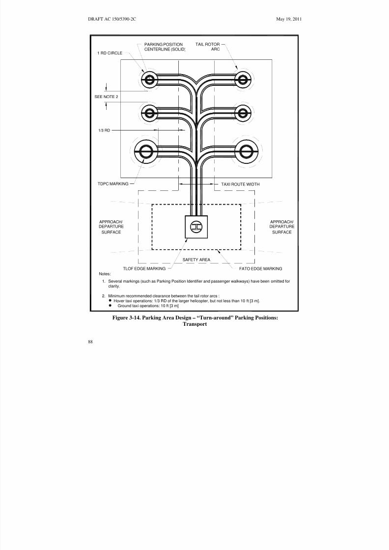
8/3/2019 draft_150_5390_2C
http://slidepdf.com/reader/full/draft15053902c 96/198
DRAFT AC 150/5390-2C May 19, 2011
PARKING POSITION TAIL ROTOR
1 RD CIRCLECENTERLINE (SOLID) ARC
SEE NOTE 2
1/3 RD
TDPC MARKING TAXI ROUTE WIDTH
APPROACH/ APPROACH/ DEPARTURE DEPARTURE
SURFACE SURFACE
SAFETY AREA
TLOF EDGE MARKING FATO EDGE MARKINGNotes:
1. Several markings (such as Parking Position Identifier and passenger walkways) have been omitted forclarity.
2. Minimum recommended clearance between the tail rotor arcs :
Hover taxi operations: 1/3 RD of the larger helicopter, but not less than 10 ft [3 m].
Ground taxi operations: 10 ft [3 m]Figure 3-14. Parking Area Design – “Turn-around” Parking Positions:
Transport
88

8/3/2019 draft_150_5390_2C
http://slidepdf.com/reader/full/draft15053902c 97/198
May 19, 2011 DRAFT AC 150/5390-2C
TLOF EDGE MARKING FATO EDGE MARKING
APPROACH/ APPROACH/ DEPARTURE DEPARTURE
SURFACE SURFACE
SAFETY AREA
TAXI ROUTE WIDTH
1/3 RD
SEE NOTE 3
TAXI ROUTE WIDTH
SHOULDER LINE
MARKING
1 RD CIRCLE PARKING POSITIONCENTERLINE (SOLID)
Notes:
1. Several markings (such as Parking Position Identifier and passenger walkways) have been omitted for clarity.
2. The parking positions are designed so that the helicopters exit taxiing forward.
3. Minimum recommended clearance between the arcs generated by the main rotor:Hover taxi operations: 1/3 RD of the larger helicopter Ground taxi operations: 10 ft [3 m]
Figure 3-15. Parking Area Design – “Taxi-through” Parking Position
89

8/3/2019 draft_150_5390_2C
http://slidepdf.com/reader/full/draft15053902c 98/198
DRAFT AC 150/5390-2C May 19, 2011
PASSENGER WALKWAY
IN BLACK AND WHITE PAINT
TDPC MARKING SHOULDER LINE(USE WITH TURN-AROUND (USE WITH TAXI-THROUGH
PARKING ONLY) ONLY)INNER DIAMETER = 6 IN [15 CM] WIDE1/2 D OF DESIGN HELICOPTER YELLOW LINE18 IN. [45.7 CM] WIDEYELLOW STRIPE
CENTERLINE12 IN [30 CM] WIDE
YELLOW LINE
10 FT [3 M]OUTER DIAMETER CIRCLE
6 IN [15 CM] WIDE
YELLOW LINE
6 IN [15 CM]WIDE STRIPE
YELLOW LINE
1 RD CIRCLE
6 IN [15 CM] WIDE
YELLOW LINE
PARKING POSITION WEIGHTLIMITATION (IF APPLICABLE)IN 3 FT [0.9 M] HIGH CHARACTERS
PARKING POSITION IDENTIFIER(LETTER OR NUMBER)IN 3 FT [0.9 M] HIGH CHARACTERS
LARGEST D THE PARKINGPOSITION WILL ACCOMMODATEIN 3 FT [0.9 M] HIGH CHARACTERS
Figure 3-16. Parking Position Identification, Size and Weight Limitations: Transport
90

8/3/2019 draft_150_5390_2C
http://slidepdf.com/reader/full/draft15053902c 99/198
May 19, 2011 DRAFT AC 150/5390-2C
(1) Systems for storing and dispensing fuel must conform to Federal, state, and localrequirements for petroleum handling facilities. Guidance is found in AC 150/5230-4, Aircraft Fuel
Storage, Handling, and Dispensing on Airports, and in appropriate National Fire Protection Association(NFPA) 403, Standard for Aircraft Rescue and Fire Fighting Services at Airports, and NFPA 418,Standards for Heliports.
(2) Fueling locations must be designed and marked to minimize the potential for helicoptersto collide with the dispensing equipment. Fueling areas should be designed so there is no object tallenough to be hit by the main or tail rotor blades within a distance of RD of the design helicopter from thecenter point of the position where the helicopter would be fueled. If this is not practical at an existingfacility, long fuel hoses should be installed.
(3) Lighting. The fueling area should be lighted if night fueling operations are contemplated.Care should be taken to ensure that any light poles do not constitute an obstruction hazard.
e. Tiedowns. Recessed tiedowns should be installed to accommodate extended or overnightparking of based or transient helicopters. Caution should be exercised to ensure that any depressionassociated with the tiedowns is of a diameter not greater than one-half the width of the smallest helicopter
landing wheel or landing skid anticipated to be operated on the heliport surface. In addition, tiedownchocks, chains, cables, and ropes should be stored off the heliport surface to avoid fouling landing gear.Guidance on tiedowns can be found in AC 20-35, Tiedown Sense.
313. HELIPORT MARKERS AND MARKINGS. Markers and/or surface markings identify thefacility as a heliport. Surface markings may be paint, reflective paint, reflective markers, or preformedmaterial. Lines/markings may be outlined with a 6-inch-wide (15 cm) line of a contrasting color toenhance conspicuity. Markings that define the edges of a TLOF, FATO, taxiway or apron are placedwithin the limits of those areas. The following markers and markings are used.
a. Heliport Identification Marking. The identification marking identifies the location as aheliport, marks the TLOF and provides visual cues to the pilot. The marking consists of a white “H.” The
height of the “H” is 0.3D. The “H” is located in the center of the TLOF and oriented on the axis of thepreferred approach/departure path. A bar may be placed under the “H” when it is necessary to distinguishthe preferred approach/departure direction. The proportions and layout of the letter “H” are illustrated inFigure 3-17 on page 92.
b. TLOF Markings.
(1) TLOF Perimeter Marking. The perimeter of a TLOF is defined with a continuous 12inch wide (30 cm), white line, as shown in Figure 3-18 on page 93.
(2) Touchdown/Positioning Circle (TDPC) Marking. A touchdown/positioning circlemarking is provided for guidance to allow a pilot to touch down in a specific position on paved surfaces.When the pilot’s seat is over the marking, the undercarriage will be inside the load-bearing area, and allparts of the helicopter will be clear of any obstacle by a safe margin. A TDPC marking is a yellow circlewith an inner diameter of 0.5 D and a line width of 18 in (0.5 m). A TDPC marking is located in thecenter of a TLOF. See Figure 3-17 on page 92.
91

8/3/2019 draft_150_5390_2C
http://slidepdf.com/reader/full/draft15053902c 100/198
DRAFT AC 150/5390-2C May 19, 2011
ALTERNATE MARKING WITH
2.
3.
DETAIL B
NO WEIGHT RESTRICTIONS
TLOF SIZE/WEIGHTLIMITATION 'BOX'
SEE DETAIL B
SEE DETAIL A
DETAIL AHELIPORT INDENTIFICATION
SYMBOL
NO WEIGHT LIMIT
Notes:
See Appendix C for the form and proportion of the numbers used in the TLOF Size and
"12" indicates the maximum takeoff weight (12,000 lbs) of the TLOF design helicopter,
"D53" indicates the overall length of the largest helicopter (53 ft) for which the TLOF is
1.
Limitation Box.
designed.
in units of thousands of pounds.
TOUCHDOWN/POSITION CIRCLEINNER DIAMETER = 1/2D OFDESIGN HELICOPTER18 IN [45.7CM] WIDEYELLOW STRIPE
PAINT
OF "H" WHITEINTERIOR
A(.30 D)
0.07A 0.02A
0.66A
0.14A
5 IN[12.7 CM]
SEE NOTE 2
SEE NOTE 3
9 FT[2.8 M]
SQUARE
Figure 3-17. Standard Heliport Identification Symbol, TLOF Size and Weight Limitations: Transport
92

8/3/2019 draft_150_5390_2C
http://slidepdf.com/reader/full/draft15053902c 101/198
ure
May 19, 2011 DRAFT AC 150/5390-2C
DETAIL A
5 FT [1.5 M]
Notes:
The "H" is orientated on the axis of the preferred approach/departure surface.1.
FATO EDGE MARKINGSEE NOTES 4 & 5 AND DETAIL A
TLOF EDGE MARKING A P P R O A C H / D E P A R T U R E
S U R F A C E
A P P R O A C H / D E P A R T U R E
S U R F A C E
SAFETY AREA
SEE NOTE 3
FATO IN-GROUND MARKING
12 IN [30 CM]
5 FT [1.5 M] MIN6 FT [2 M] MAX
TDPCMARKING
The perimeter of the TLOF and FATO are marked.2.
3.
4.
The perimeter of a paved or hard surfaced TLOF is defined with a continuous12 in [30 cm] white line.
Paved FATO perimeters are defined with a 12 in [30 cm] wide dashed line per Detail A.
5.
6. See Fig 3-17 for " H", Touchdown/Position, Overall Length and Weight Limitation boxdimensions.
Unpaved FATO perimeters are defined with a flush in-ground marker per Detail A.
Figure 3-17
Figure 3-18. Paved TLOF/Paved FATO – Paved TLOF/Unpaved FATO – Marking: Transport
93

8/3/2019 draft_150_5390_2C
http://slidepdf.com/reader/full/draft15053902c 102/198
DRAFT AC 150/5390-2C May 19, 2011
(3) TLOF Size and Weight Limitations. The TLOF is marked to indicate the length andweight of the largest helicopter for which it is designed, as shown in Figure 3-17 on page 92. Thesemarkings are contained in a box that is located in the lower right-hand corner of the TLOF, or the onright-hand side of the “H” of a circular TLOF, when viewed from the preferred approach direction. Thenumbers are 5 feet (1.5 m) high (see Figure C–2 on page 188). The numbers are black with a whitebackground.
(4) TLOF Size Limitation. This number is the length (D) of the largest helicopter for whichit is designed, as shown in Figure 3-17 on page 92. The marking consists of the letter “D” followed by thedimension in feet. Metric equivalents are not used for this purpose. This marking is centered in the lowersection of the TLOF size/weight limitation box.
(5) TLOF Weight Limitations. If a TLOF has limited weight-carrying capability, it ismarked with the maximum takeoff weight of the design helicopter, in units of thousands of pounds, asshown in Figure 3-17 on page 92. Metric equivalents are not be used for this purpose. This marking iscentered in the upper section of a TLOF size/weight limitation box. If the TLOF does not have a weightlimit, a diagonal line, extending from the lower left hand corner to the upper right hand corner, should beadded to the upper section of the TLOF size/weight limitation box.
c. FATO Markings.
(1) FATO Perimeter Marking.
(a) Paved FATOs. The perimeter of a paved FATO is defined with a 12-inch wide (30cm) dashed white line. The corners of the FATO are defined and the perimeter marking segments are 12inches in width, approximately 5 feet (1.5 m) in length, and with end-to-end spacing of approximately 5feet (1.5 m). See Figure 3-18 on page 93.
(b) Unpaved FATOs. The perimeter of an unpaved FATO is marked with 12-inch wide(30 cm), flush in-ground markers. The corners of the FATO are defined and the perimeter markers are 12
inches in width, approximately 5 feet (1.5 m) in length, and with end-to-end spacing of approximately 5feet (1 5 m). Figure 3-18 on page 93.
d. Flight Path Alignment Guidance Marking. An optional flight path alignment guidancemarking consists of one or more arrows to indicate the preferred approach/departure direction(s). It ismarked on the TLOF, FATO and/or safety area surface as shown in Figure 3-9 on page 81. The shaft of the arrow is 18 in. (50 cm) in width and at least 10 feet (3 m) in length. When combined with a flight pathalignment guidance lighting system described in paragraph 314.g on page 99, it takes the form shown inFigure 3-9 on page 81, which includes scheme for marking the arrowheads. The markings must be in acolor that provides good contrast against the background color of the surface on which they are marked.In the case of a flight path limited to a single departure path, the arrow marking is unidirectional. In thecase of a heliport with only a bidirectional approach /takeoff flight path available, the arrow marking isbidirectional.
e. Taxiway and Taxi Route Markings.
(1) Taxiway Markings. The centerline of a taxiway is marked with a continuous 6-inch (15cm) yellow line. Both edges of the taxiway are marked with two continuous 6- inch wide (15 cm) yellowlines spaced 6 inches (15 cm) apart. Figure 3-11 on page 83 illustrates taxiway centerline and edgemarkings.
94
8/3/2019 draft_150_5390_2C
http://slidepdf.com/reader/full/draft15053902c 103/198
May 19, 2011 DRAFT AC 150/5390-2C
(2) Taxiway to Parking Position Transition Requirements. For paved taxiways andparking areas, taxiway centerline markings continue into parking positions and become the parkingposition centerlines.
f. Helicopter Parking Position Markings. Helicopter parking positions have the followingmarkings.
(1) Paved Parking Position Identifications. Parking position identifications (numbers orletters) are marked if there is more than one parking position. These markings are yellow characters 3 feet(0.9 m) high. (See Figure 3-16 on page 90, and Figure C–1 on page 187).
(2) Rotor Diameter Circle. A 6-inch-wide (15 cm), solid yellow line defines a circle of theRD of the largest helicopter that will park at that position. The RD is measured at the outside edge of thecircle. See Figure 3-12 on page 85.
(3) Touchdown/Positioning Circle (TDPC) Marking. An optional touchdown/positioningcircle marking provides guidance to allow a pilot to touch down in a specific position on paved surfaces.When the pilot’s seat is over the marking, the undercarriage will be inside the load-bearing area, and all
parts of the helicopter will be clear of any obstacle by a safe margin. A TDPC marking is a yellow circlewith an inner diameter of 0.5 D and a line width of 18 in (0.5 m). A TDPC marking is located in thecenter of a parking area. See Figure 3-16 on page 90. A TDPC marking is recommended for “turnaround” parking areas.
(4) Maximum Length Marking. A marking on paved surfaces indicates the D of the largesthelicopter that the position is designed to accommodate (e.g., 49). This marking is in yellow characters atleast 3 feet (0.9 m) high. (See Figure 3-17 on page 92 and Figure C–1 on page 187.)
(5) Parking Position Weight Limit. If a paved parking position has a weight limitation, it isstated in units of 1,000 pounds as illustrated in Figure 3-16 on page 90. (A 12 indicates a weight-carryingcapability of up to 9,000 pounds. Metric equivalents are not be used for this purpose.) This marking
consists of yellow characters 3 feet (0.9 m) high. A bar may be placed under the number to minimize thepossibility of being misread. (See Figure 3-17 on page 92 and Figure C–1 on page 187).
(6) Shoulder Line Markings. Optional shoulder line markings are used for paved parkingareas (Figure 3-12 on page 85) to ensure safe rotor clearance. A 6-inch-wide (15 cm) solid yellowshoulder line, perpendicular to the centerline and extending to the RD marking, is located so it is underthe pilot’s shoulder such that the main rotor of the largest helicopter for which the position is designedwill be entirely within the rotor diameter parking circle. See Figure 3-16 on page 90. A shoulder linemarking is recommended for “taxi through” parking areas.
(7) Walkways. Figure 3-12 on page 85 illustrates one marking scheme.
g. Closed Heliport. All markings of a permanently closed heliport, FATO, or TLOF should beobliterated. If it is impractical to obliterate markings, a yellow “X” should be placed over the “H”, asillustrated in Figure 3-19 below. The yellow “X” must be large enough to ensure early pilot recognitionthat the heliport is closed. The wind cone(s) and other visual indications of an active heliport must also beremoved.
h. Marking Sizes. See Appendix C on page 187 for guidance on the proportions of paintednumbers.
95
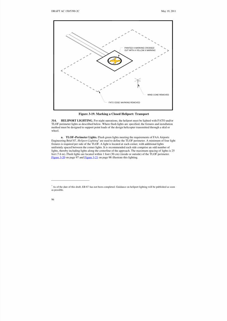
8/3/2019 draft_150_5390_2C
http://slidepdf.com/reader/full/draft15053902c 104/198
DRAFT AC 150/5390-2C May 19, 2011
FATO EDGE MARKING REMOVED
WIND CONE REMOVED
OUT WITH A YELLOW X MARKING
PAINTED H MARKING CROSSED
Figure 3-19. Marking a Closed Heliport: Transport
314. HELIPORT LIGHTING. For night operations, the heliport must be lighted with FATO and/orTLOF perimeter lights as described below. Where flush lights are specified, the fixtures and installationmethod must be designed to support point loads of the design helicopter transmitted through a skid orwheel.
a. TLOF–Perimeter Lights. Flush green lights meeting the requirements of FAA AirportsEngineering Brief 87, Heliport Lighting2 are used to define the TLOF perimeter. A minimum of four lightfixtures is required per side of the TLOF. A light is located at each corner, with additional lightsuniformly spaced between the corner lights. It is recommended each side comprise an odd number of lights, thereby including lights along the centerline of the approach. The maximum spacing of lights is 25feet (7.6 m). Flush lights are located within 1 foot (30 cm) (inside or outside) of the TLOF perimeter.Figure 3-20 on page 97 and Figure 3-21 on page 98 illustrate this lighting.
2 As of the date of this draft, EB 87 has not been completed. Guidance on heliport lighting will be published as soonas possible.
96

8/3/2019 draft_150_5390_2C
http://slidepdf.com/reader/full/draft15053902c 105/198
May 19, 2011 DRAFT AC 150/5390-2C
P R E F E R R E D A P P R O A C H C
5 L A N D I N G L
I G H T S ( O P T I O N A L )
L
F i g u r e 3 - 2 4
S E E F I G U R E
3 - 2 4 F O R D E T A I L S
F L U S H T L O F E
D G E L I G H T S
G R E
E N I N - P A V E M E N T
T A X I W A Y C E N T E R L I N E L I G H T S
L I G H T E D W I N D C O N E
F L U S H T L O F E D G E L I G H T S
1 F T [ 3 0 C M ]
F L U
S H F A T O E D G E L I G H T S
F L U S
H I N - P A V E M E N T L I G H T D E T A I L
N o t e s :
1 . F l u s h
F A T O a n d T L O F p e r i m e t e r l i g h t s m a y b e i n s t a l l e d i n s i d e o r o u t s i d e w
i t h i n 1 f t [ 3 0 c m ] o f t h e F A T O a n d T
L O F
r e s p e
c t i v e p e r i m e t e r s .
Figure 3-20. TLOF and FATO Flush Perimeter Lighting: Transport
2 . T L O F
s i z e a n d w e i g h t l i m i t a t i o n b o x i s n o t s h o w n f o r c l a r i t y .
97
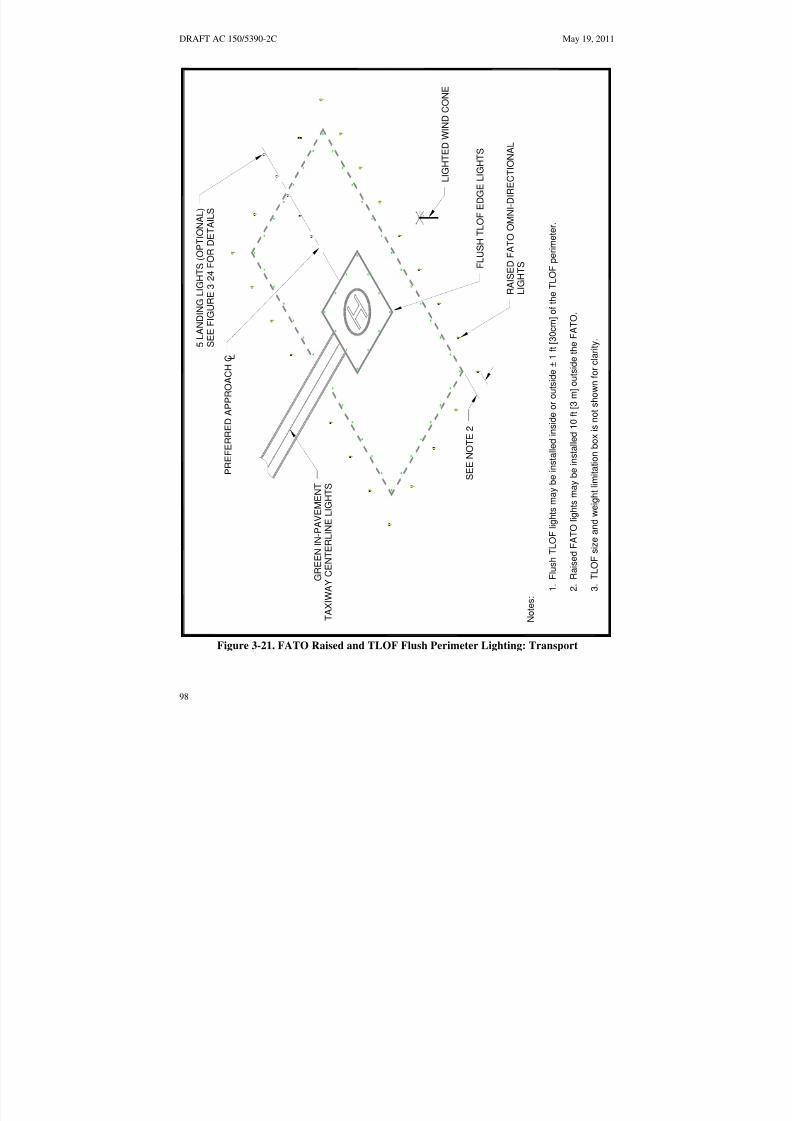
8/3/2019 draft_150_5390_2C
http://slidepdf.com/reader/full/draft15053902c 106/198
DRAFT AC 150/5390-2C May 19, 2011
5 L A N D I N G L I G H T S ( O P T I O N A L )
S E E F I G U R E 3 -
2 4 F O R D E T A I L S
P R E F E R R E D A P P R O A C H C L
G R E
E N I N - P A V E M E N T
T A X I W A Y C E
N T E R L I N E L I G H T S
L I G H T E D W I N D C O N E
S E E N O T E 2
F L U S H T L O F E D G E L I G H T S
R A I S E D F A T O O M N I - D I R E C T I O N A L
L I G
H T S
N o t e s :
1 . F l u s h T L O F l i g h t s m a y b e i n s t a l l e d i n s i d e o r o u t s i d e ± 1 f t [ 3 0 c m ] o f t h e T L O F p e r i m e t e r .
2 . R a i s e d F A T O l i g h t s m a y b e i n s t a l l e d 1 0 f t [ 3 m ] o u t s i d e t h e F A T O .
3 . T L O
F s i z e a n d w e i g h t l i m i t a t i o n b o x i s
n o t s h o w n f o r c l a r i t y .
Figure 3-21. FATO Raised and TLOF Flush Perimeter Lighting: Transport
98

8/3/2019 draft_150_5390_2C
http://slidepdf.com/reader/full/draft15053902c 107/198
May 19, 2011 DRAFT AC 150/5390-2C
b. Optional TLOF Lights. An optional feature is a line of 7 green, flush lights meeting thestandards of EB 87 spaced at 5-foot (1.5 m) intervals installed in the TLOF pavement. These lights arealigned on the centerline of the approach course to provide close-in directional guidance and improveTLOF surface definition. These lights are illustrated in Figure 3-22 on page 100.
c. Ground Level FATO Perimeter Lights. Green lights meeting the requirements of EB 87
are used to define the limits of the FATO. A light is located at each corner with additional lightsuniformly spaced between the corner lights with a maximum interval of 25 feet (8 m) between lights. It isrecommended each side comprise an odd number of lights, thereby including lights along the centerline of the approach. If flush lights are used, they are located within 1 foot (30 cm) inside or outside of the FATOperimeter. If raised light fixtures are used, they must be no more than 8 inches (20 cm) high, located 10feet (3 m) out from the FATO perimeter, and must not penetrate a horizontal plane at the FATO elevationby more than 2 inches (5 cm). See Figure 3-21 on page 98.
d. Elevated FATO–Perimeter Lights. Lighting for an elevated FATO is the same as for aground level FATO except that lights may be located at the outside edge of the safety net, as shown in
Figure 3-23 on page 101. The raised lights must not penetrate a horizontal plane at the FATO elevationby more than 2 inches (5 cm). In areas where it snows in the winter, the outside edge of the safety net is
the preferred location.
e. Floodlights. If ambient light does not adequately illuminate markings for night operations,floodlights should be used to illuminate the TLOF, the FATO, and /or the parking apron. To eliminate theneed for tall poles, these floodlights may be mounted on adjacent buildings. Care should be taken,however, to place floodlights clear of the TLOF, the FATO, the safety area, and the approach/departuresurfaces and transitional surfaces. Care should be taken to ensure that floodlights and their associatedhardware do not constitute an obstruction hazard. Floodlights should be aimed down and provideillumination on the apron surface. Floodlights that might interfere with pilot vision during takeoff andlandings should be capable of being turned off by pilot control or at pilot request.
f. Landing Direction Lights. Landing direction lights are an optional feature to be installed
when it is necessary to provide directional guidance. Landing direction lights are a configuration of fivewhite omnidirectional lights meeting the standards of EB 87 on the centerline of the preferredapproach/departure path. These lights are spaced at 15-foot (4.6 m) intervals beginning at a point not lessthan 30 feet (9 m) and not more than 60 feet (18 m) from the TLOF perimeter and extending outward inthe direction of the preferred approach/departure path, as illustrated in Figure 2-26 on page 102.
g. Flight Path Alignment Lights. Flight path alignment lights meeting the requirements of EB87 are optional. They are placed in a straight line along the direction of approach and/or departure flightpaths. The lights may extend across the TLOF, FATO, safety area or any suitable surface in theimmediate vicinity of the FATO or safety area. Lights in the TLOF or FATO must be flush lights. Threeor more white lights are spaced at 5 feet (1.5 m) to 10 feet (3.0 m). (See Figure 3-9 on page 81.)
99

8/3/2019 draft_150_5390_2C
http://slidepdf.com/reader/full/draft15053902c 108/198
DRAFT AC 150/5390-2C May 19, 2011
LEGEND
OPTIONAL GREEN FLUSH L-805A TYPETLOF LIGHTS ON 5 FT [1.5 M] CENTERS. Note: Not drawn to scale
Figure 3-22. Optional TLOF Lights: Transport
100

8/3/2019 draft_150_5390_2C
http://slidepdf.com/reader/full/draft15053902c 109/198
May 19, 2011 DRAFT AC 150/5390-2C
SAFETY NET
B
NOT LESS THAN 5 FT [1.5 M]
NOT MORE THAN2 IN [5 CM]
12 IN [30 CM]
AC
(SURROUNDINGTHE FATO)
Three possible locations for FATO edge lighting:
Flush edge fixtures
Omni-directional light, mounted off FATO edge
Omni-directional light, mounted off outer edge of safety net (preferred locationin snow areas)
A
B
C
FALL PROTECTION:
RECOMMENDED IFABOVE 30 IN [0.8 M]
REQUIRED IF
ABOVE 4 FT [1.2 M]
Figure 3-23. Elevated FATO – Perimeter Lighting: Transport
101

8/3/2019 draft_150_5390_2C
http://slidepdf.com/reader/full/draft15053902c 110/198
DRAFT AC 150/5390-2C May 19, 2011
NOT LESS THAN30 FT [9 M]
NOR MORE THAN60 FT [18 M]
4 EQUAL SPACES@ 15 FT [4.6 M]= 60 FT [18.4 M]
FATO
TLOF
OMNI-DIRECTIONAL WHITE LIGHTS
LEGEND
Note: Not drawn to scale
Figure 3-24. Landing Direction Lights: Transport
102

8/3/2019 draft_150_5390_2C
http://slidepdf.com/reader/full/draft15053902c 111/198
May 19, 2011 DRAFT AC 150/5390-2C
h. Taxiway and Taxi Route Lighting.
(1) Taxiway Centerline Lights. Taxiway centerlines are defined with flush bidirectionalgreen lights meeting the standards of AC 150/5345-46 for type L-852A (straight segments) or L-852B(curved segments). These lights are spaced at maximum 50-foot (15 m) longitudinal intervals on straightsegments and at maximum 25-foot (7.5 m) intervals on curved segments, with a minimum of four lights
needed to define the curve. Taxiway centerline lights may be uniformly offset no more than two feet toease painting the taxiway centerline. Retroreflective markers are not permitted.
(2) Taxiway Edge Lights. Flush omnidirectional blue lights meeting the standards of AC150/5345-46 for type L-852T are used to mark the edges of a taxiway. Retroreflective markers are notpermitted.
(a) Straight Segments. Lights are spaced at 50 feet (15.2 m) longitudinal intervals onstraight segments.
(b) Curved Segments. Curved taxiway edges require shorter spacing of edge lights. Thespacing is determined based on the radius of the curve. The applicable spacing for curves is the shown in
Figure 17 of AC 150/5340-30, Design and Installation Detail for Airport Visual Aids. The taxiway edgelights are uniformly spaced. Curved edges of more than 30 degrees from point of tangency (PT) of thetaxiway section to PT of the intersecting surface must have at least three edge lights. For radii not listed inFigure 17 determine spacing by linear interpolation.
i. Heliport Identification Beacon. A heliport identification beacon must be installed. Thebeacon, flashing white/green/yellow at the rate of 30 to 45 flashes per minute, must be located on or closeto the heliport. Guidance on heliport beacons is found in AC 150/5345-12, Specification for Airport and
Heliport Beacon.
315. MARKING AND LIGHTING OF DIFFICULT-TO-SEE OBJECTS. Unmarked wires,antennas, poles, cell towers, and similar objects are often difficult to see, even in the best daylight
weather, in time for a pilot to successfully take evasive action. While pilots can avoid such objects duringen route operations by flying well above them, approaches and departures require operations near theground where obstacles may be a factor. This paragraph discusses the marking and lighting of objectsnear, but outside and below the approach/departure surface. Guidance on marking and lighting objects iscontained in AC 70/7460-1, Obstruction Marking and Lighting.
a. Airspace. If difficult-to-see objects penetrate the object identification surfaces illustrated inFigure 3-25 on page 104, these objects must be marked to make them more conspicuous. If operations areconducted at a heliport between dusk and dawn, these difficult-to-see objects must be lighted. The objectidentification surfaces in Figure 3-25 on page 104 are described as follows:
(1) In all directions from the safety area except under the approach/departure paths, theobject identification surface starts at the safety area perimeter and extends out horizontally for a distanceof 100 feet (30.5 m).
(2) Under the approach/departure surface, the object identification surface starts from theoutside edge of the FATO and extends horizontally out for a distance of 800 feet (244 m). From thispoint, the object identification surface extends out for an additional distance of 3,200 feet (975 m) whilerising on an 8:1 slope (8 units horizontal in 1 unit vertical). From the point 800 feet (244 m) from theFATO perimeter, the object identification surface is 100 feet (30.5 m) beneath the approach/departuresurface.
103

8/3/2019 draft_150_5390_2C
http://slidepdf.com/reader/full/draft15053902c 112/198
DRAFT AC 150/5390-2C May 19, 2011
(3) The width of this object identification surface under the approach/departure surfaceincreases as a function of distance from the safety area. From the safety area perimeter, the objectidentification surface extends laterally to a point 100 feet (30.5 m) outside the safety area perimeter. Atthe upper end of the surface, the object identification surface extends laterally 200 feet (61 m) on eitherside of the approach/departure path.
b. Shielding of Objects. If there are a number of objects close together, it may not be necessaryto mark all of them if they are shielded. To meet the shielding guidelines an object must be shielded byexisting structures of a permanent and substantial character or by natural terrain or topographic features of equal or greater height, and must be located in the congested area of a city, town, or settlement where it isevident beyond all reasonable doubt that the structure so shielded will not adversely affect safety in airnavigation. Additional guidance on this topic may be found in 14 CFR part 77.9, Construction or
alteration requiring notice.
( 8 : 1 S L O
P E )
APPROACH/DEPARTURE SURFACE
( 8 : 1 S L O
P E )
OBJECT IDENTIFICATION SURFACE
FATO
400 FT
[122 M]
100 FT[30 M]
500 FT[152 M]
3,200 FT [975 M]
500 FT[152 M]
100 FT [30 M]FROM EDGE
OF SAFETY AREA
100 FT [30 M] FROM EDGE OF SAFETY AREA
100 FT [30 M] R200 FT[61 M]
Note: Not drawn to scale
Figure 3-25. Airspace Where Marking and Lighting are Recommended: Transport
104

8/3/2019 draft_150_5390_2C
http://slidepdf.com/reader/full/draft15053902c 113/198
May 19, 2011 DRAFT AC 150/5390-2C
316. SAFETY CONSIDERATIONS. Some safety enhancements to be considered in the design of aheliport are discussed below. Other areas such as the effects of rotor downwash may need to be addressedbased on site conditions and the design helicopter.
a. Security. The operational areas of a heliport need to be kept clear of people, animals, andvehicles.
(1) Safety Barrier. At ground-level transport heliports, the heliport owner or operator musterect a safety barrier around the helicopter operational areas. This barrier may take the form of a fence ora wall. It must be no closer to the operation areas than the outer perimeter of the safety area. Barriersshould not penetrate any approach/departure (primary or transitional) surface. Thus, in the vicinity of theapproach/departure paths, the barrier may need to be well outside the outer perimeter of the safety area.
(2) Any barrier must be high enough to present a positive barrier to persons inadvertentlyentering an operational area and yet low enough to be non-hazardous to helicopter operations.
(3) Access to airside areas must be through controlled and locked gates and doors. Gates anddoors should display a cautionary sign similar to that illustrated in Figure 3-26 on page 106.
b. Rescue and Fire-Fighting Services. Heliports must meet State and local rescue and fire-fighting regulations. A fire hose cabinet or extinguisher must be provided at each access gate and eachfueling location. At elevated TLOF/FATOs, fire hose cabinets, fire extinguishers, and other fire-fightingequipment must be located adjacent to, but below the level, of the TLOF/FATO. Information is availablein NFPA 418, Standards for Heliports, and NFPA 403, Standard for Aircraft Rescue and Fire-Fighting
Services at Airports. NFPA standards are available at the NFPA web site http://www.nfpa.org.
c. Communications. A Common Traffic Advisory Frequency (CTAF) radio may be used toprovide arriving helicopters with heliport and traffic advisory information but may not be used to controlair traffic. The Federal Communications Commission (FCC) should be contacted for information onCTAF licensing.
d. Weather Information. An automated weather observing system (AWOS) measures andautomatically broadcasts current weather conditions at the heliport site. When an AWOS is installed, itmust be located at least 100 feet (30 m) and not more than 700 feet (213 m) from the TLOF. Locate theAWOS so its instruments will not be affected by rotor wash from helicopter operations. Guidance onAWOS systems is found in AC 150/5220-16, Automated Weather Observing Systems (AWOS) for Non-
Federal Applications, and FAA Order 6560.20, Siting Criteria for Automated Weather Observing Systems
(AWOS).
e. Winter Operations. Swirling snow raised by a helicopter’s rotor wash can cause the pilot tolose sight of the intended landing point and/or hide objects that need to be avoided. At least the TLOF, theFATO, and as much of the safety area as practical, should be kept free of snow. Heliport design shouldtake into account the methods and equipment to be used for snow removal. The heliport design shouldallow the snow to be removed sufficiently so that the snow will not present an obstruction hazard to eitherthe tail rotor or the main rotor. Guidance on winter operations is found in AC150/5200-30, Airport Winter
Safety and Operations.
105
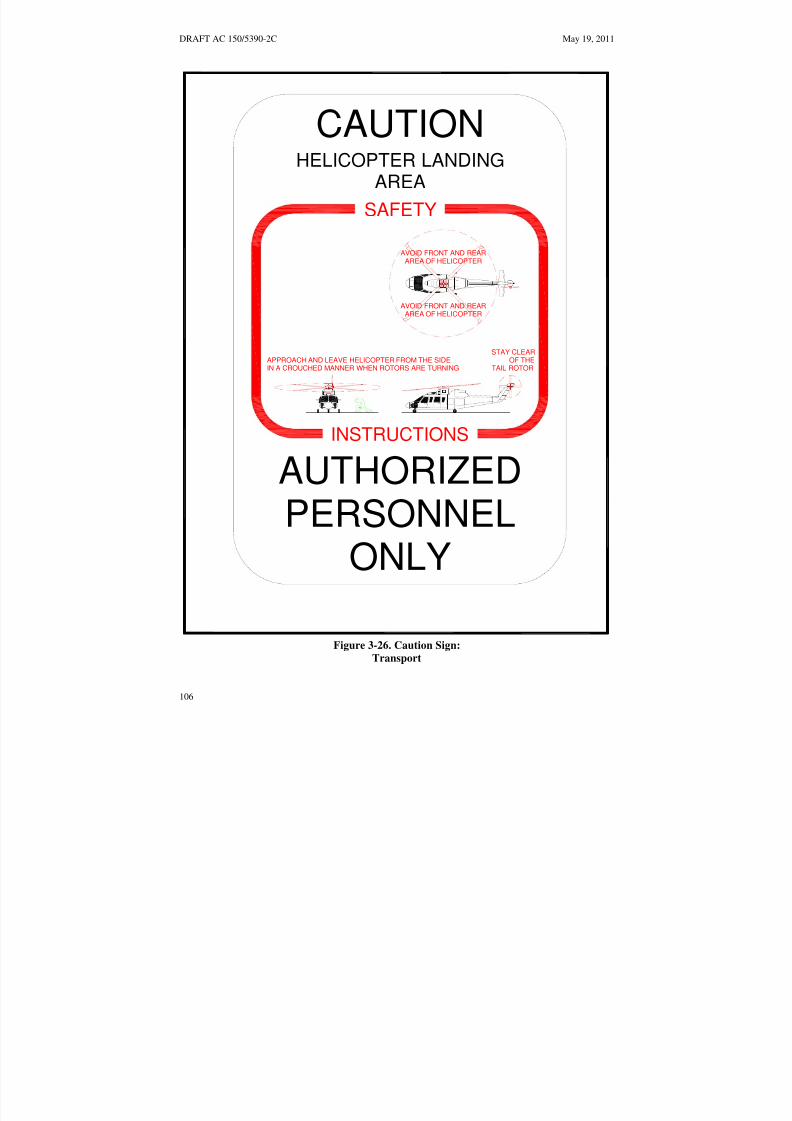
8/3/2019 draft_150_5390_2C
http://slidepdf.com/reader/full/draft15053902c 114/198
DRAFT AC 150/5390-2C May 19, 2011
CAUTION
HELICOPTER LANDINGAREA
SAFETYAVOID FRONT AND REAR
AREA OF HELICOPTER
AVOID FRONT AND REARAREA OF HELICOPTER
STAY CLEARAPPROACH AND LEAVE HELICOPTER FROM THE SIDE OF THEIN A CROUCHED MANNER WHEN ROTORS ARE TURNING TAIL ROTOR
INSTRUCTIONSAUTHORIZEDPERSONNEL
ONLYFigure 3-26. Caution Sign:
Transport
106

8/3/2019 draft_150_5390_2C
http://slidepdf.com/reader/full/draft15053902c 115/198
May 19, 2011 DRAFT AC 150/5390-2C
317. VISUAL GLIDESLOPE INDICATORS (VGSI). A visual glideslope indicator (VGSI)provides pilots with visual vertical course and descent cues. The lowest on-course visual signal mustprovide a minimum of 1 degree of clearance over any object that lies within 10 degrees of the approachcourse centerline.
a. Siting. The optimum location of a VGSI is on the extended centerline of the approach path at
a distance that brings the helicopter to a hover with the undercarriage between 3 and 8 feet (0.9 to 2.4 m)above the TLOF. Figure 3-27 below illustrates VGSI clearance criteria. This will require estimating thevertical distance from the undercarriage to the pilot’s eye.
b. Control of the VGSI. It is permissible for the VGSI to be pilot controllable such that it is“on” only when required.
c. VGSI Needed. A VGSI is an optional feature. However, a VGSI should be provided if one ormore of the following conditions exist, especially at night:
(1) Obstacle clearance, noise abatement, or traffic control procedures require a particularslope to be flown.
(2) The environment of the heliport provides few visual surface cues.
d. Additional Guidance. AC 150/5345-52, Generic Visual Glideslope Indicators (GVGI), andAC 150/5345-28, Precision Approach Path Indicator (PAPI) Systems, provide additional guidance.
107

8/3/2019 draft_150_5390_2C
http://slidepdf.com/reader/full/draft15053902c 116/198
L O W E R L I M I T O
F T H E O N- C O U R
S E S I G NA L
OBS TACLE CLEAR
ANCE REFERENCE
LINE
L O W E R L I M I T O
F T H E O N- C O
U R S E S I G NA L
OBS TACLE CLEAR
ANCE REFERENC
E LINE
DRAFT AC 150/5390-2C May 19, 2011
10°
OBSTACLE CLEARANCE
PLANE
COURSE CENTERLINE
VISUAL GLIDESLOPE
INDICATOR (VGSI)
10°
CRITICAL
OBJECT
1°MINIMUM CLEARANCE
VISUAL GLIDESLOPE
INDICATOR (VGSI)
VARIABLE SEE DETAIL BELOW
PILOT'S EYES
VISUAL GLIDESLOPEINDICATOR (VGSI)
3 FT TO 8 FT[1 M TO 2.4 M]
Note: Not drawn to scale
Figure 3-27. Visual Glideslope Indicator Siting and Clearance Criteria:
Transport
108

8/3/2019 draft_150_5390_2C
http://slidepdf.com/reader/full/draft15053902c 117/198
May 19, 2011 DRAFT AC 150/5390-2C
318. TERMINAL FACILITIES.
a. Design Considerations. The heliport terminal requires curbside access for passengers usingprivate autos, taxicabs, and public transit vehicles. Public waiting areas need the usual amenities, and acounter for rental car services may be desirable. Passenger auto parking areas should accommodatecurrent requirements and have the capability of being expanded to meet future requirements. Readily
available public transportation may reduce the requirement for employee and service personnel autoparking spaces. The heliport terminal building or sheltered waiting area should be attractive andfunctional. AC 150/5360-9, Planning and Design of Airport Terminal Building Facilities at Non-Hub
Locations, contains guidance on designing terminal facilities.
b. Security. Unless screening was carried out at the helicopter passengers’ departure location,Transportation Security Administration regulations may require that a screening area and/or screening beprovided before passengers enter the airport's secured areas. Multiple helicopter parking positions and/orlocations may be needed in the terminal area to service helicopter passenger and/or cargo inter connectingneeds. Information about passenger screening is available at Transportation Security Administration website http://www.tsa.gov/public /.
319. ZONING AND COMPATIBLE LAND USE. Where state and local statutes permit, thetransport heliport operator is encouraged to promote the adoption of the following zoning measures toensure that the heliport will continue to be available for public use and to protect the community'sinvestment in the facility.
a. Zoning to Limit Building/Object Heights. General guidance on drafting an ordinance thatwould limit building and object heights is contained in AC 150/5190-4, A Model Zoning Ordinance to
Limit Height of Objects Around Airports. The locally developed ordinance should substitute the heliportsurfaces for the airport surfaces described in the model ordinance.
b. Zoning for Compatible Land Use. A zoning ordinance may be enacted, or an existingordinance modified, to control the use of property within the Heliport Protection Zone. The ordinance
should restrict activities to those that are compatible with helicopter operations. See paragraph 309 onpage 78.
c. Air rights and property easements are options that may be used to prevent the encroachmentof obstacles in the vicinity of a heliport.
109

8/3/2019 draft_150_5390_2C
http://slidepdf.com/reader/full/draft15053902c 118/198
DRAFT AC 150/5390-2C May 19, 2011
Intentionally left blank
110

8/3/2019 draft_150_5390_2C
http://slidepdf.com/reader/full/draft15053902c 119/198
May 19, 2011 DRAFT AC 150/5390-2C
CHAPTER 4. HOSPITAL HELIPORTS 401. GENERAL. Helicopters are often used to transport injured persons from the scene of an accidentto a hospital and to transfer patients from one hospital to another. This chapter addresses issues that areunique to hospital heliports and issues for which the design recommendations are different than what is
recommended for other categories of heliports. These recommendations address the design of a heliportthat will accommodate air ambulance helicopter operations and emergency medical service (EMS)personnel and equipment. The design recommendations given in this chapter are based on theunderstanding that there will never be more than one helicopter within the final approach and takeoff area(FATO) and the associated safety area. If there is a need for more than one touchdown and lift-off area(TLOF) at a heliport, each TLOF should be located within its own FATO. Consider the feasibility of accommodating large military helicopters that might be used in an emergency.
402. ACCESS BY INDIVIDUALS WITH DISABILITIES. Hospital heliports by their nature mustbe accessible to individuals with disabilities. The legal requirement, however, is that heliports operated bypublic entities and those receiving Federal financial assistance must meet accessibility requirements. Seeparagraph 112 on page 12.
403. HELIPORT SITE SELECTION.
a. Planning. Public agencies and others planning to develop a hospital heliport are encouragedto select a site capable of supporting instrument operations, future expansion, and military helicopters thatwill be used in disaster relief efforts.
b. Property Requirements. A functional hospital heliport may be as simple as a cleared area onthe ground, together with a wind cone and a clear approach/departure path. Figure 4-1 on page 112illustrates the essential elements of a ground-level hospital heliport.
c. Turbulence. Air flowing around and over buildings, stands of trees, terrain irregularities, etc.
can create turbulence on ground-level and roof-top heliports that may affect helicopter operations. Wherethe FATO is located near the edge and top of a building or structure, or within the influence of turbulentwakes from other buildings or structures, the turbulence and airflow characteristics in the vicinity of, andacross the surface of the FATO should be assessed to determine if an air-gap between the roof, roof parapet or supporting structure, and/or some other turbulence mitigating design measure is necessary.FAA Technical Report FAA/RD-84/25, Evaluating Wind Flow Around Buildings on Heliport Placement
(Reference 34 on page 190 addresses the wind’s effect on helicopter operations). The following actionsmay be taken in selecting a site to minimize the effects of turbulence.
(1) Ground-Level Heliports. Helicopter operations from sites immediately adjacent tobuildings, trees, and other large objects are subjected to air turbulence effects caused by such features.Therefore, locate the landing and takeoff area away from such objects in order to minimize air turbulence
in the vicinity of the FATO and the approach/departure paths.
(2) Elevated Heliports. Establishing a 6 foot (1.8 m) or more air gap above the level of theroof will generally minimize the turbulent effect of air flowing over the roof edge. If an air gap or someother turbulence mitigating design measure is warranted but not practical, operational limitations mayneed to be considered under certain wind conditions. If an air gap is included in the design it should bekept free at all times of significant objects that would obstruct the airflow.
111

8/3/2019 draft_150_5390_2C
http://slidepdf.com/reader/full/draft15053902c 120/198
DRAFT AC 150/5390-2C May 19, 2011
LIGHTED WIND CONE
TLOF EDGE MARKING
SECURITY FENCE
SAFETY AREA
APPROACH/ DEPARTURE
FATO EDGE MARKINGSURFACE
APPROACH/ DEPARTURE
HOSPITAL MARKING:SURFACE
RED "H"WHITE CROSS
WARNING SIGNS:"DO NOT ENTER WHEN
HELICOPTER IS PRESENT"
Note: The security fence and wind cone should be located so that they will not interferewith the approach/departure path or transitional surface.
Figure 4-1. Essential Features of a Ground-level Hospital Heliport: Hospital
d. MAGNETIC RESONANCE IMAGERS (MRI). Hospital equipment, such as an MRI usedin diagnostic work, can create a strong magnetic field that will cause temporary aberrations in thehelicopter's magnetic compass and may interfere with other navigational systems. Heliport proponents
should be alert to the location of any MRI with respect to the heliport location. A warning sign alertingpilots to the presence of an MRI is recommended. Steps should be taken to inform pilots of the locationsof MRIs and other similar equipment. For additional information, see reference 35 on page 190.
112

8/3/2019 draft_150_5390_2C
http://slidepdf.com/reader/full/draft15053902c 121/198
May 19, 2011 DRAFT AC 150/5390-2C
FATO
B
E
F
A C
G
DIM
C
E
F
ITEM VALUE
1.5D
1.5D
G see Table 4-1
NOTES
A
B
TLOF
.75D - .5RD
40 ft [12 m]
40 ft [12 m]1RD but not less thanMinimum TLOF Length
Minimum TLOF Width
Minimum Safety Area Width
Minimum Separation
Between the Perimetersof the TLOF and FATO
1RD but not less than
Minimum FATO Width
Minimum FATO Length
See Paragraph 406.b.(1)
above 1,000 ftfor adjustments of elevations
Table 4-1
SAFETY AREA
Note: For circular TLOFs and FATOs, dimensions A, B, C and E refer to diameters.
Figure 4-2. TLOF/FATO Safety Area Relationships and Minimum Dimension: Hospital
404. BASIC LAYOUT. The heliport consists of a TLOF contained within a FATO. A safety area isprovided around the FATO. The relationship of the TLOF to the FATO and the safety area is shown inFigure 4-2 above. A FATO may not contain more than one TLOF. Appropriate approach/departureairspace, to allow safe approaches to and departures from landing sites is required. (See paragraph 408 onpage 120.)
113

8/3/2019 draft_150_5390_2C
http://slidepdf.com/reader/full/draft15053902c 122/198
DRAFT AC 150/5390-2C May 19, 2011
405. TOUCHDOWN AND LIFTOFF AREA (TLOF).
a. TLOF Location. The TLOF of a hospital heliport may be at ground level, on an elevatedstructure, or at rooftop level. The TLOF is normally centered within the FATO.
b. TLOF Size. The minimum TLOF dimension (length, width, or diameter) is equal to the rotor
diameter (RD) of the design helicopter but not less than 40 feet (12 m). Increasing the load-bearing area(LBA) centered on the TLOF may provide some safety and operational advantages. TLOF dimensionsmay be increased to enhance safety factors and/or operational efficiency.
(1) Elevated Hospital Heliport. If the FATO outside the TLOF is non-load-bearing, theminimum width, length or diameter of the TLOF is increased to the overall length (D) of the designhelicopter.
(2) Elongated TLOF. An elongated TLOF can provide an increased safety margin andgreater operational flexibility. An elongated TLOF may contain a landing position located in the centerand two takeoff positions located at either end as illustrated in Figure 4-3 on page 115. The landingposition must have a minimum length of 1.0 times the RD of the design helicopter. If an elongated TLOF
is provided an elongated FATO is also required.
c. Ground-level TLOF Surface Characteristics. The entire TLOF must be dynamic loadbearing.
(1) Design Loads. The TLOF and any supporting TLOF structure must be capable of supporting the dynamic loads of the design helicopter.
(2) Paving. The TLOF surface must be either paved or aggregate-turf (see AC 150/5370-10,Items P-217 and P-501). portland cement concrete (PCC) is recommended for ground-level facilities. Anasphalt surface is less desirable for heliports as it may rut under the wheels or skids of a parked helicopter.This has been a factor in some rollover accidents. Pavements should have a broomed or other roughened
finish that provides a skid-resistant surface for helicopters and non-slippery footing for people.
d. Rooftop and Other Elevated TLOFs.
(1) Design Loads. Elevated TLOFs and any TLOF supporting structure must be capable of supporting the dynamic loads of the design helicopter.
114

8/3/2019 draft_150_5390_2C
http://slidepdf.com/reader/full/draft15053902c 123/198
see Table 4-1
May 19, 2011 DRAFT AC 150/5390-2C
A
B
C
E
F
E
F
TAKEOFF POSITION
TAKEOFF POSITION
FATO
LANDING POSITION
TLOF
SAFETY AREA
DIM ITEM VALUE NOTES
A Minimum TLOF Width 1RD but not less then 40 ft [12 m]
B Minimum TLOF/Landing Position Length 1RD but not less then 40 ft [12 m]
C Minimum FATO Width 1.5D
E
Minimum Separation
Between the Perimetersof the TLOF and FATO
.75D - .5RD
F Minimum Safety Area Width See Table 4-1
Note: For circular TLOFs, dimensions A and B refer to diameters.
Figure 4-3. An Elongated FATO with Two Takeoff Positions: Hospital
(2) Elevation. The TLOF must be elevated above the level of any obstacle in the FATO andsafety area that cannot be removed, except for frangibly mounted objects that, due to their function, mustbe located within the safety area (see paragraph 407.d on page 118.
(3) Obstructions. Elevator penthouses, cooling towers, exhaust vents, fresh-air vents, andother raised features can affect heliport operations. Control mechanisms should be established to ensurethat obstruction hazards are not installed after the heliport is operational.
115
8/3/2019 draft_150_5390_2C
http://slidepdf.com/reader/full/draft15053902c 124/198
DRAFT AC 150/5390-2C May 19, 2011
(4) Air Quality. Helicopter exhaust can affect building air quality if the heliport is too closeto fresh air vents. When designing a building intended to support a helipad, locate fresh air ventsaccordingly. When adding a helipad to an existing building, fresh air vents may have to be relocated.
(5) TLOF Surface Characteristics. Rooftop and other elevated heliport TLOFs must beconstructed of metal, concrete, or other materials subject to local building codes. TLOF surfaces must
have a finish that provides a skid-resistant surface for helicopters and non-slippery footing for people.
(6) Safety Net. If the platform is elevated 4 feet or more above its surroundings, title 29 CFRpart 1910.23, Guarding Floor and Wall Openings and Holes, requires the provision of fall protection. TheFAA recommends that such protection be provided for all platforms elevated 30 inches (76 cm) or more.However, permanent railings or fences must not be used since they would be safety hazards duringhelicopter operations. An alternate method of installing a safety net, meeting state and local regulation butnot less than 5 feet (1.5 m) wide, is suggested. The safety net should have a load carrying capability of 25lbs/ft2 (122 kg/m2). The net, as illustrated in Figure 4-29 on page 154 must not project above the level of the TLOF. Both the inside and outside edges of the safety net should be fastened to a solid structure. Netsshould be constructed of material that is resistant to environmental effects.
(7) Access to Elevated TLOFs. Title 29 CFR part 1936, Means of Egress requires twoseparate access points for an elevated structure such as an elevated TLOF. Hospital heliports shouldprovide access to and from the TLOF via a ramp in order to provide for quick and easy transportation of apatient on a gurney. Ramps should be built in accordance with state and local requirements. The width of the ramp, and any turns in the ramp, should be wide enough to accommodate a gurney with a personwalking on each side. Straight segments of the ramp should be not less than 6 feet (1.8 m) wide.Additional width may be required in the turns. The ramp surface should provide a slip-resistant surface.The slope of the ramp should be no steeper than 12:1 (12 unit horizontal in 1 units vertical). While it ispossible to move a gurney to and from the TLOF using a lift, this is not recommended since it invariablyresults in a delay in the movement of patients in time-critical conditions. If stairs are used, they must bebuilt in compliance with title 29 CFR part 1910.24, Fixed Industrial Stairs. Handrails required by thisstandard must fold down or be removable to below the level of the TLOF so that they will not be hazards
during helicopter operations.
e. TLOF Gradients. Recommended TLOF gradients are defined in Chapter 7 on page 173.
406. FINAL APPROACH AND TAKEOFF AREA (FATO). A hospital heliport must have at leastone FATO. The FATO must contain a TLOF within its borders at which arriving helicopters terminatetheir approach and from which departing helicopters take off.
a. FATO Location. The FATO of a hospital heliport may be at ground level, on an elevatedstructure, or on a rooftop. To avoid or minimize the need for additional ground transport, the FATOlocation should provide ready access to the hospital's emergency room. However, the heliport should belocated so buildings and other objects are outside the safety area and below obstacle clearance surfaces.
The relationship of the FATO to the TLOF and the safety area is shown in Figure 4-2 on page 113.
b. FATO Size.
(1) The minimum width, length or diameter of a FATO is 1.5 times the overall length (D) of the design helicopter. At elevations well above sea level a longer FATO is needed to provide an increasedsafety margin and greater operational flexibility. The additional FATO length is depicted in Figure 4-4.
116
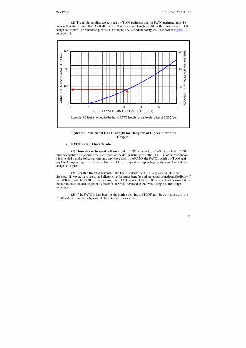
8/3/2019 draft_150_5390_2C
http://slidepdf.com/reader/full/draft15053902c 125/198
May 19, 2011 DRAFT AC 150/5390-2C
(2) The minimum distance between the TLOF perimeter and the FATO perimeter must benot less than the distance 0.75D – 0.5RD where D is the overall length and RD is the rotor diameter of thedesign helicopter. The relationship of the TLOF to the FATO and the safety area is shown in Figure 4-2on page 113.
300
200
100
00 1 2 3 4 5 6
0
90
60
30
A D D I T I O N T
O F A T O L E N G T H I N F E E T
A D D I T I O N T O
F A T O L E N G T H I N M E T E R S
SITE ELEVATION (IN THOUSANDS OF FEET)
Example: 80 feet is added to the basic FATO length for a site elevation of 3,200 feet.
Figure 4-4. Additional FATO Length for Heliports at Higher Elevation: Hospital
c. FATO Surface Characteristics.
(1) Ground-level hospital heliports. If the TLOF is marked, the FATO outside the TLOFmust be capable of supporting the static loads of the design helicopter. If the TLOF is not marked and/orit is intended that the helicopter can land anywhere within the FATO, the FATO outside the TLOF andany FATO supporting structure must, like the TLOF, be capable of supporting the dynamic loads of thedesign helicopter.
(2) Elevated hospital heliports. The FATO outside the TLOF may extend into clear
airspace. However, there are some helicopter performance benefits and increased operational flexibility if the FATO outside the TLOF is load bearing. The FATO outside of the TLOF must be load-bearing unlessthe minimum width and length or diameter of TLOF is increased to the overall length of the designhelicopter.
(3) If the FATO is load bearing, the portion abutting the TLOF must be contiguous with theTLOF and the adjoining edges should be at the same elevation.
117

8/3/2019 draft_150_5390_2C
http://slidepdf.com/reader/full/draft15053902c 126/198
DRAFT AC 150/5390-2C May 19, 2011
(4) If the FATO is unpaved, the FATO must be treated to prevent loose stones and any otherflying debris caused by rotor downwash.
(5) When the FATO or the load-bearing area in which it is located is elevated 4 feet or moreabove its surroundings, title 29 CFR part 1910.23 Guarding Floor and Wall Openings and Holes, requiresthe provision of fall protection. However, permanent railings or fences must not be used since they would
be safety hazards during helicopter operations. An alternate method of installing a safety net, meetingstate and local regulations but not less than 5 feet (1.5 m) wide, is suggested. The safety net should have aload carrying capability of 25 lbs/ft2 (122 kg/m2). The net, as illustrated in Figure 4-29 on page 154, mustnot project above the level of the TLOF. Both the inside and outside edges of the safety net should befastened to a solid structure. Nets should be constructed of material that is resistant to environmentaleffects.
d. Mobile Objects within the FATO. The FATO design recommendations in this AC are basedon the assumption that the FATO is closed to other aircraft if a helicopter or other mobile object is withinthe FATO or the associated safety area.
e. Fixed Objects within the FATO. No fixed objects are permitted within a FATO except for
frangibly mounted objects that, due to their aeronautical function, must be located there. Those objectswhose functions require them to be located within the FATO must not exceed a height of 2 inches (5 cm)above the elevation of the TLOF perimeter.
f. FATO/FATO Separation. If a heliport has more than one FATO, the separation between theperimeters of the two FATOs must be such that the respective safety areas do not overlap. This separationis based on the assumption that simultaneous approach/departure operations will not take place. If simultaneous operations are planned, a minimum 200 foot (61 m) separation is required.
g. FATO Gradients. Recommended FATO gradients are defined in Chapter 7.
407. SAFETY AREA. A safety area surrounds a FATO and should be clear of all obstacles except
small, frangible objects that, because of their function, must be located there.
a. Safety Area Width. The required width of the safety area is shown in
b. below, and is the same on all sides. The width is affected by the provision or absence of standard heliport markings. The safety area may extend into clear airspace.
c. Mobile Objects within the Safety Area. The safety area design recommendations of this ACare based on the assumption that the TLOF and FATO are closed to other aircraft if a helicopter or othermobile object is within the FATO or the safety area.
d. Fixed Objects within a Safety Area. No fixed objects are permitted within a safety areaexcept for frangibly mounted objects that, due to their function, must be located there. Those objectswhose functions require them to be located within the safety area must not exceed a height of 8 inches (20cm) above the elevation of the FATO perimeter nor penetrate the approach/departure surfaces ortransitional surfaces.
e. Safety Area Surface. The safety area need not be load bearing. Figure 4-5 on page 120depicts a non-load-bearing safety area. If possible, the portion of the safety area abutting the FATOshould be contiguous with the FATO with the adjoining edges at the same elevation. This is needed in
118

8/3/2019 draft_150_5390_2C
http://slidepdf.com/reader/full/draft15053902c 127/198
May 19, 2011 DRAFT AC 150/5390-2C
order to avoid the risk of catching a helicopter skid or wheel. The safety area should be treated to preventloose stones and any other flying debris caused by rotor wash.
f. Safety Gradients. Recommended safety area gradients are defined in Chapter 7 on page 173.
Table 4-1. Minimum VFR Safety Area Width as a Function of Hospital Heliport Markings
TLOF perimeter marked:
FATO perimeter marked:
Standard Hospital markingsymbol:
Yes
Yes
Yes
Yes
Yes
No
No
Yes
Yes
No
Yes
No
Hospital heliports: 1/3 RD but
not less than
10 ft (3 m)**
1/3RD but
not less than
20 ft (6 m)**
½ D but
not less than
20 ft (6 m)
½ D but
not less than
30 ft (9 m)
D: overall length of the design helicopter
RD: rotor diameter of the design helicopter
** Also applies when the FATO is not marked. The FATO should not be marked if (a) the FATO (or partof the FATO) is a non-load bearing surface and/or (b) the TLOF is elevated above the level of asurrounding load bearing area.
119
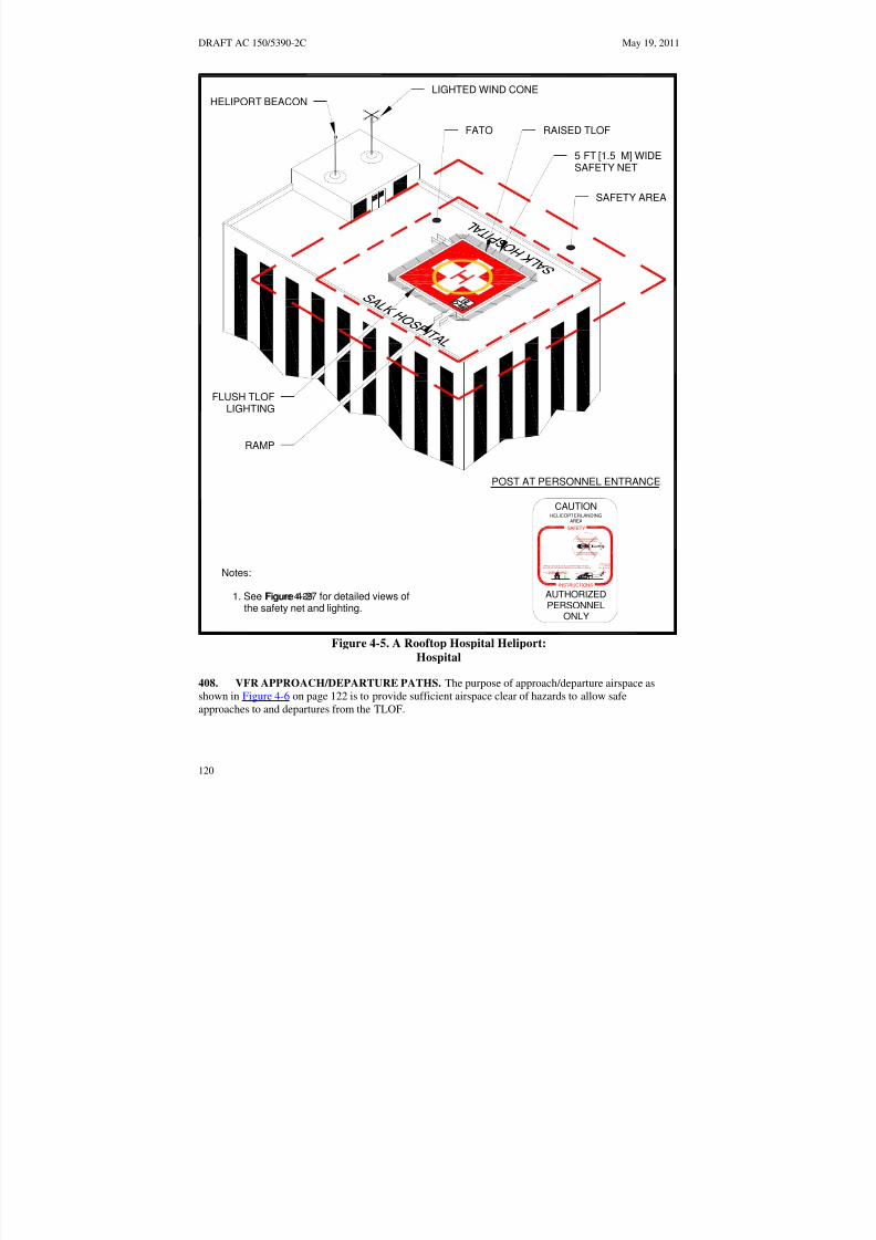
8/3/2019 draft_150_5390_2C
http://slidepdf.com/reader/full/draft15053902c 128/198
DRAFT AC 150/5390-2C May 19, 2011
LIGHTED WIND CONEHELIPORT BEACON
FATO RAISED TLOF
5 FT [1.5 M] WIDESAFETY NET
SAFETY AREA
FLUSH TLOFLIGHTING
RAMP
POST AT PERSONNEL ENTRANCE
CAUTIONHELICOPTER LANDING
AREA
SAFETY
AVOIDFRONT AND REARAREAOF HELICOPTER
AVOIDFRONT AND REARAREAOF HELICOPTER
STAYCLEARA P PR OA C H A N D L EA V E HE L IC OP TER FR OMTH E SI D E O F TH EINACROUCHED MANNERWHEN ROTORSARETURNING TAIL ROTOR
Notes:INSTRUCTIONS
Figure 4-29 AUTHORIZEDPERSONNEL
1. See Figure 4-27 for detailed views ofthe safety net and lighting.
ONLY
Figure 4-5. A Rooftop Hospital Heliport: Hospital
408. VFR APPROACH/DEPARTURE PATHS. The purpose of approach/departure airspace asshown in Figure 4-6 on page 122 is to provide sufficient airspace clear of hazards to allow safeapproaches to and departures from the TLOF.
120

8/3/2019 draft_150_5390_2C
http://slidepdf.com/reader/full/draft15053902c 129/198
May 19, 2011 DRAFT AC 150/5390-2C
a. Number of Approach/Departure Paths. Preferred approach/departure paths should bealigned with the predominant wind direction so that downwind operations are avoided and crosswindoperations are kept to a minimum. To accomplish this, a heliport should have more than oneapproach/departure path. Other approach/departure paths should be based on the assessment of theprevailing winds or, when this information is not available, the separation between such flight paths andthe preferred flight path should be at least 135 degrees. (See Figure 4-6 on page 122). Hospital facilities
may have only a single approach/departure path although a second flight path provides additional safetymargin and operational flexibility.
b. VFR Approach/Departure and Transitional Surfaces. Figure 4-6 on page 122 illustratesthe approach/departure and transitional surfaces.
(1) An approach/departure surface is centered on each approach/departure path. Theapproach/departure path starts at the edge of the FATO and slopes upward at 8:1 (8 units horizontal in 1unit vertical) for a distance of 4,000 feet (1219 m) where the width is 500 feet (152 m) at a height of 500feet (152 m) above the heliport elevation.
(2) The transitional surfaces start from the edges of the FATO parallel to the flight path
center line, and from the outer edges of approach/departure surface, and extend outwards at a slope of 2:1(2 units horizontal in 1 unit vertical) for a distance of 250 feet (76 m) from the centerline. The transitionalsurface is not applied on the FATO edge opposite the approach/departure surface. See Figure 4-8 on page124.
(3) The approach/departure and transitional surfaces must be free of penetrations unless anFAA aeronautical study determines such penetrations not to be hazards. Such aeronautical studies areconducted only at public heliports and private airports with FAA-approved approach procedures.Paragraph 109 on page 9 provides additional information on hazards to air navigation.
(4) At hospital heliports, the size of the 8:1 approach/departure surface may be increased fora distance of 2,000 feet (610 m) as shown in Figure 4-8 on page 124 and Figure 4-9 on page 125 in lieu of
considering transitional surfaces. The lateral extensions on each side of the 8:1 approach/departuresurface start at the width of the FATO and are increased so that at a distance of 2,000 feet (610 m) fromthe FATO they are 100 feet (30 m) wide. Penetrations of obstacles into area A or area B, but not both,may be allowed providing the penetrations are marked or lighted and not considered a hazard.
c. Curved VFR Approach/Departure Paths. VFR approach/departure paths may include onecurve. Such paths may use the airspace above public lands, such as freeways or rivers. However, thedesign of curved approach/departure paths must consider the performance capabilities of the helicoptersintended to be served by the heliport. Where a curved portion of the approach/departure path is provided,the sum of the radius of arc defining the center line and the length of the straight portion originating at theFATO must not be less than 1,886 feet (575 m). The minimum radius for curved approach/departure pathsis 886 feet (270m) following a 1,000 feet (305m) straight section. The combined length of the center line
of the curved portion and the straight portion must be 4,000 feet (1219 m). See Figure 4-7 on page 123.Figure 4-9 on page 125 shows a curved approach/departure path for an 8:1 approach/departure surface.
121

8/3/2019 draft_150_5390_2C
http://slidepdf.com/reader/full/draft15053902c 130/198
DRAFT AC 150/5390-2C May 19, 2011
FATO
PREDOMINATE WIND DIRECTIONSURFACE BASED UPON THE
PREFERRED APPROACH/DEPARTURE
APPROACH/ DEPARTURE
SURFACE(TYPICAL)
SEE DETAIL
OPPOSITE
HELIPORT
135°
SHADED AREATO HAVE SAME
CHARACTERISTICS
AS FATO
250 FT [76 M]
500 FT [152 M]
500 FT[152 M]
4,000 FT[1,219 M]
LEGEND
8:1 Approach/Departure
Surface250 FT FATO
[76 M]2:1 Transitional Surface
500 FT
[152 M]
Note: Not drawn to scale
Figure 4-6. VFR Heliport Approach/Departure and Transitional Surfaces: Hospital
122

8/3/2019 draft_150_5390_2C
http://slidepdf.com/reader/full/draft15053902c 131/198
May 19, 2011 DRAFT AC 150/5390-2C
500 FT
[152 M]
1,000 FT [305 M]
R = 886 FT
[270 M]
500 FT[152 M]
R = 1,886 FT [575 M]
Legend:
8:1 Approach/DepartureSurface2:1 Transitional Surface
Notes:
1. Any combination of straight portions and one curved portion may be established using the following formula:S + R 1,886 ft [575 m] and R 886 ft [270 m], where S is the length of the straight portion(s) and R is the
radius of the turn. Note that any combination 1,886 ft [575 m] will work.
2. The minimum total length of the centerline of the straight and curved portion is 4,000 ft [1,219 m].
3. Helicopter take-off performance is reduced in a curve. Consider a straight portion along the take-off climb surface prior to the start of the curve to allow for acceleration.
Figure 4-7. Curved Approach/Departure: Hospital
123

8/3/2019 draft_150_5390_2C
http://slidepdf.com/reader/full/draft15053902c 132/198
P
E
8 : 1 A P P R O A C H / D E
A R T U R E S U R F A C
DRAFT AC 150/5390-2C May 19, 2011
P e n e t r a t i o n ( s ) o f A o r B a r e a b u t n o t b o t h a r e
a s a l l o w e d
i f m a r
k e d o r l i g h t e d a n d i f n o t c o n s i d e r e d a h a z a r d
1 0 0 F T [ 3 0 M ]
A
F A T O
5 0 0 F T
A P P R O A C H / D E P A R T U R E S U R F A C E
8 : 1
[ 1 5 2 M ]
B
1 0 0 F T [ 3 0 M ]
2 , 0 0 0 F T [ 6 1 0 M ]
4 , 0 0 0 F T [ 1 , 2 1 9 M ]
P L A N V I E W
2 , 0 0 0 F T [ 6 1 0 M ]
5 0 0 F T
[ 1 5 2 M ]
F A T O
2 5 0 F T [ 7 6 M ]
E L E V A T I O N V I E W
Figure 4-8. VFR Heliport Lateral Extension of the 8:1 Approach/Departure Surface:
Hospital
124
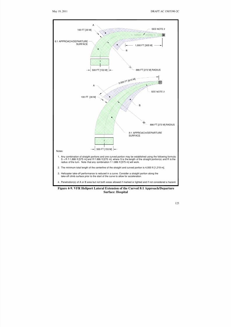
8/3/2019 draft_150_5390_2C
http://slidepdf.com/reader/full/draft15053902c 133/198
2, 0 0 0 F T [ 6 1
0 M ]
May 19, 2011 DRAFT AC 150/5390-2C
A
SEE NOTE 2100 FT [30 M]
8:1 APPROACH/DEPARTURESURFACE
1,000 FT [305 M]
B
886 FT [272 M] RADIUS500 FT [153 M]
A
SEE NOTE 2
100 FT [30 M]
B
886 FT [272 M] RADIUS
8:1 APPROACH/DEPARTURESURFACE
500 FT [153 M]Notes:
1. Any combination of straight portions and one curved portion may be established using the following formula:S + R 1,886 ft [575 m] and R 886 ft [270 m], where S is the length of the straight portion(s) and R is theradius of the turn. Note that any combination 1,886 ft [575 m] will work.
2. The minimum total length of the centerline of the straight and curved portion is 4,000 ft [1,219 m].
3. Helicopter take-off performance is reduced in a curve. Consider a straight portion along the take-off climb surface prior to the start of the curve to allow for acceleration.
4. Penetration(s) of A or B area but not both areas allowed if marked or lighted and if not considered a hazard.
Figure 4-9. VFR Heliport Lateral Extension of the Curved 8:1 Approach/Departure
Surface: Hospital
125

8/3/2019 draft_150_5390_2C
http://slidepdf.com/reader/full/draft15053902c 134/198
DRAFT AC 150/5390-2C May 19, 2011
d. Flight Path Alignment Guidance. Optional flight path alignment markings and/or flightpath alignment lights (see paragraph 414.e below) may be used where it is desirable and practicable toindicate available approach and/or departure flight path direction(s). See Figure 4-10 on page 127.
e. Periodic Review of Obstructions. Heliport operators should reexamine obstacles in thevicinity of 8:1 approach/departure paths on at least an annual basis. This reexamination should include an
appraisal of the growth of trees near approach and departure paths. Paragraph 109 on page 9 providesadditional information on hazards to air navigation.
409. HELIPORT PROTECTION ZONE (HPZ) It is recommended that a Heliport Protection Zonebe established for each approach/departure surface. The HPZ is the area under the 8:1 approach/departuresurface starting at the FATO perimeter and extending out for a distance of 280 feet (85.3 m), as illustratedin Figure 4-11 on page 128. The HPZ is intended to enhance the protection of people and property on theground. This is achieved through heliport owner control over the HPZ. Such control includes clearingHPZ areas (and maintaining them clear) of incompatible objects and activities. Land uses discouraged inthe HPZ are residences and places of public assembly. (Churches, schools, hospitals, office buildings,shopping centers, and other uses with similar concentrations of persons typify places of public assembly.)Fuel storage facilities should not be located in the HPZ.
410. WIND CONE.
a. Specification. A wind cone conforming to AC 150/5345-27, Specification for Wind Cone
Assemblies, must be used to show the direction and magnitude of the wind. The wind cone should providethe best possible color contrast to its background.
b. Wind Cone Location. The wind cone must be located so it provides the pilot with valid winddirection and speed information in the vicinity of the heliport under all wind conditions.
(1) At many landing sites, there may be no single, ideal location for the wind cone. At othersites, it may not be possible to site a wind cone at the ideal location. Consequently, more than one wind
cone may be required in order to provide the pilot with all the wind information needed for safeoperations.
(2) A pilot on the approach path must be able to see a wind cone clearly when the helicopteris at a distance of 500 feet (152 m) from the TLOF.
(3) Pilots must also be able to see a wind cone from the TLOF.
(4) To avoid presenting an obstruction hazard, the wind cone(s) must be located outside thesafety area, and it must not penetrate the approach/departure or transitional surfaces.
c. Wind Cone Lighting. For night operations, the wind cone must be illuminated, eitherinternally or externally, to ensure that it is clearly visible.
126

8/3/2019 draft_150_5390_2C
http://slidepdf.com/reader/full/draft15053902c 135/198
May 19, 2011 DRAFT AC 150/5390-2C
BIDIRECTIONAL AND SINGLE FLIGHT PATHS
SAFETY AREA
SINGLE FLIGHTPATH MARKING
FATOBI-DIRECTIONIONALFLIGHT PATH MARKING
TLOF
SEE DETAIL A
10 FT [3.0 M]5 FT [1.5 M]
MINIMUM
1.5 FT
[0.46 M]
LIGHTS (3 MINIMUM)5 FT5 - 10 FT[1.5 M]
[1.5 - 3.0 M] SPACING
DETAIL A FLIGHT PATH ALIGNMENT MARKING DETAIL
Notes (arrow): Notes (lights):
1. Arrowheads must have constant 1. Light type: omni-directional inset whitedimensions lights
2. Stroke length may be adjusted to match length 2. Lights may be outside arrowavailable (Minimum length: 10 ft [3 m])
Figure 4-10. Flight Path Alignment Marking and Lights: Hospital
127
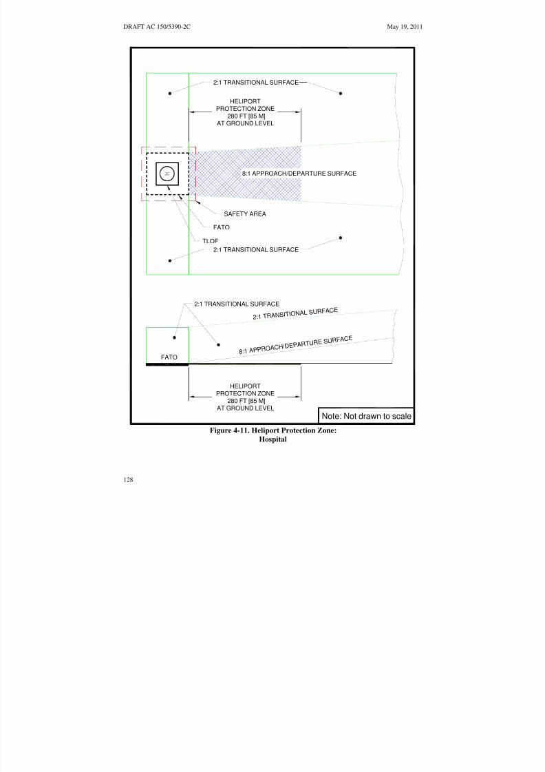
8/3/2019 draft_150_5390_2C
http://slidepdf.com/reader/full/draft15053902c 136/198
8:1 APPR OAC H
/DEPAR T URE S URFAC
E
2:1 TRANSI TIONAL S
URFACE
DRAFT AC 150/5390-2C May 19, 2011
2:1 TRANSITIONAL SURFACE
HELIPORTPROTECTION ZONE
280 FT [85 M]AT GROUND LEVEL
8:1 APPROACH/DEPARTURE SURFACE
SAFETY AREA
FATO
TLOF
2:1 TRANSITIONAL SURFACE
2:1 TRANSITIONAL SURFACE
FATO
HELIPORTPROTECTION ZONE
280 FT [85 M]AT GROUND LEVEL
Note: Not drawn to scale
Figure 4-11. Heliport Protection Zone:
Hospital
128
8/3/2019 draft_150_5390_2C
http://slidepdf.com/reader/full/draft15053902c 137/198
May 19, 2011 DRAFT AC 150/5390-2C
411. TAXIWAYS AND TAXI ROUTES. Taxiways and taxi routes are provided for the movement of helicopters from one part of a landing facility to another. They provide a connecting path between theFATO and a parking area. They also provide a maneuvering aisle within the parking area. A taxi routeincludes the taxiway plus the appropriate clearances needed on both sides. The relationship between ataxiway and a taxi route is illustrated in Figure 4-12 on page 130, Figure 4-13 on page 131, and Figure4-14 on page 132. At hospital heliports with no parking or refueling area outside the TLOF(s), no taxi
route or taxiway is required.
a. Taxiway/Taxi Route Widths. The dimensions of taxiways and taxi routes are a function of helicopter size, taxiway/taxi route marking, and type of taxi operations (ground taxi versus hover taxi).These dimensions are defined in Table 4-2 on page 133. Normally, the requirement for hover taxi dictatesthe taxiway/taxi route widths. However, when the fleet comprises a combination of large ground taxiinghelicopters and smaller air taxiing helicopters, the larger aircraft may dictate the taxiway/taxi routewidths. If wheel-equipped helicopters taxi with wheels not touching the surface, the facility should bedesigned with hover taxiway widths rather than ground taxiway widths. Where the visibility of thecenterline marking cannot be guaranteed at all times, such as locations where snow or dust commonlyobscure the centerline marking and it is not practical to remove it, the minimum taxiway/taxi routedimensions should be determined as if there was no centerline marking.
b. Surfaces. Ground taxiways must have a surface that is portland cement concrete, asphalt or asurface, such as turf, stabilized in accordance with the recommendations of Items P-217 of AC 150/537010. Unpaved portions of taxiways and taxi routes must have a turf cover or be treated in some way toprevent dirt and debris from being raised by a taxiing helicopter’s rotor wash.
c. Gradients. Recommended taxiway and taxi route gradients are defined in Chapter 7 on page 173.
129

8/3/2019 draft_150_5390_2C
http://slidepdf.com/reader/full/draft15053902c 138/198
TABLE 4 2
DRAFT AC 150/5390-2C May 19, 2011
PAVED TAXIWAY WIDTH
NOT LESS THAN TWO TIMESTHE UNDERCARRIAGE WIDTH
OF THE DESIGN HELICOPTER
TAXIWAY EDGE MARKING:
TWO CONTINUOUS 6 IN [15 CM]
YELLOW LINES SPACED 6 IN [15 CM] APART
TAXI ROUTE WIDTH
SEE - FORTAXIWAY/TAXI ROUTE WIDTH
TAXIWAY CENTERLINE MARKING:
CONTINUOUS 6 IN [15 CM] YELLOW LINE
Table 4-2
Figure 4-12. Taxiway/Taxi Route Relationship – Paved Taxiway:
Hospital
130

8/3/2019 draft_150_5390_2C
http://slidepdf.com/reader/full/draft15053902c 139/198
May 19, 2011 DRAFT AC 150/5390-2C
T A X I W A Y R A I S E D E D G E M A R K E R S
S P A C I N G : 1 5 F T [ 4 . 6 M ] O N S T R A I G H T
S E G M E N T S
1 0 F T [ 3 . 0 M ] O N C U R V E D S E G M E N T S
U N P A V E D T A X I W
A Y W I D T H
1 R D B U T N O T
M O R E
T H A N 3 5 F T [ 1 0 . 7 M ]
T A X I W A Y / T A X I
R O U T E W I D T H
S E E T A B L E 4 - 2
T a b l e
4 - 2
4 I N [ 1 0 C M ] D I A X
6 I N [ 1 5 C M ] H I G H M A X
C Y L I N D E R O N A
2 I N [ 5 C M ] S U P P O R T
1
2 I N [ 3 0 C M ] M I N D I A D I S C
A T G R A D E O R
N O
T T O E X C E E D 3 I N [ 7 C M ]
T A X I W A Y R A
I S E D E D G E
M A R K E R
D E T A I L
N o t e : N o t d r a w n t o s c a l e
Figure 4-13. Taxiway/Taxi Route Relationship – Unpaved Taxiway with Raised Edge
Markers:
Hospital
131
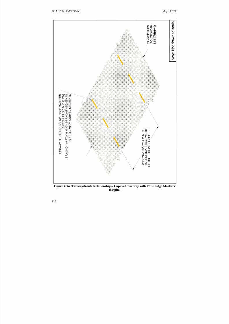
8/3/2019 draft_150_5390_2C
http://slidepdf.com/reader/full/draft15053902c 140/198
DRAFT AC 150/5390-2C May 19, 2011
T A X I W A Y F L U S H I N - G R O U N D
E D G E M A R K E R S
5 F T
X 1 F T [ 1 . 5 M X 3 0 C M ]
S P A C I N G : 1 5 F T [ 4 . 6 M ] O N S
T R A I G H T S E G M E N T S
1 0 F T [ 3 . 0 M ] O N
C U R V E D S E G M E N T S
U
N P A V E D T A X I W A Y W I D T H
2 X
U N D E R C A R R I A G E W I D T H
T A X I W A Y / T A X I
O F
T H E D E S I G N H E L I C O P T E R
R O
U T E W I D T H
S E E T A B L E 4 - 2
T a b l e
4 - 2
N o t e : N o t d r a
w n t o s c a l e
Figure 4-14. Taxiway/Route Relationship – Unpaved Taxiway with Flush Edge Markers:
Hospital
132
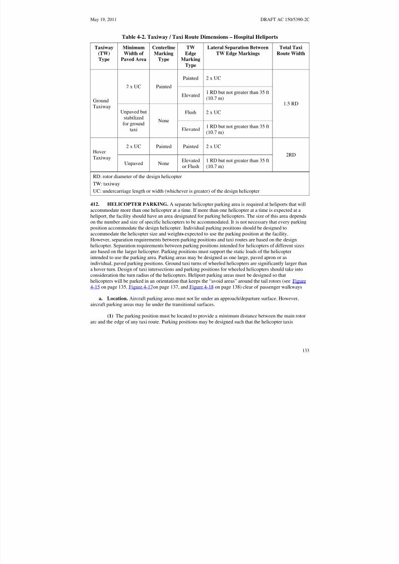
8/3/2019 draft_150_5390_2C
http://slidepdf.com/reader/full/draft15053902c 141/198
May 19, 2011 DRAFT AC 150/5390-2C
Table 4-2. Taxiway / Taxi Route Dimensions – Hospital Heliports
Taxiway
(TW)
Type
Minimum
Width of
Paved Area
Centerline
Marking
Type
TW
Edge
Marking
Type
Lateral Separation Between
TW Edge Markings
Total Taxi
Route Width
GroundTaxiway
2 x UC Painted
Painted 2 x UC
1.5 RD
Elevated1 RD but not greater than 35 ft(10.7 m)
Unpaved butstabilizedfor ground
taxi
None
Flush 2 x UC
Elevated1 RD but not greater than 35 ft(10.7 m)
HoverTaxiway
2 x UC Painted Painted 2 x UC
2RD
Unpaved NoneElevatedor Flush
1 RD but not greater than 35 ft(10.7 m)
RD: rotor diameter of the design helicopter
TW: taxiway
UC: undercarriage length or width (whichever is greater) of the design helicopter
412. HELICOPTER PARKING. A separate helicopter parking area is required at heliports that willaccommodate more than one helicopter at a time. If more than one helicopter at a time is expected at aheliport, the facility should have an area designated for parking helicopters. The size of this area dependson the number and size of specific helicopters to be accommodated. It is not necessary that every parkingposition accommodate the design helicopter. Individual parking positions should be designed toaccommodate the helicopter size and weights expected to use the parking position at the facility.However, separation requirements between parking positions and taxi routes are based on the designhelicopter. Separation requirements between parking positions intended for helicopters of different sizesare based on the larger helicopter. Parking positions must support the static loads of the helicopterintended to use the parking area. Parking areas may be designed as one large, paved apron or asindividual, paved parking positions. Ground taxi turns of wheeled helicopters are significantly larger thana hover turn. Design of taxi intersections and parking positions for wheeled helicopters should take intoconsideration the turn radius of the helicopters. Heliport parking areas must be designed so thathelicopters will be parked in an orientation that keeps the “avoid areas” around the tail rotors (see Figure
4-15 on page 135, Figure 4-17on page 137, and Figure 4-18 on page 138) clear of passenger walkways
a. Location. Aircraft parking areas must not lie under an approach/departure surface. However,aircraft parking areas may lie under the transitional surfaces.
(1) The parking position must be located to provide a minimum distance between the main rotorarc and the edge of any taxi route. Parking positions may be designed such that the helicopter taxis
133
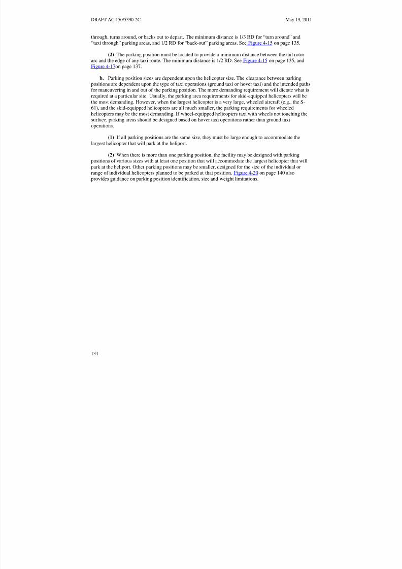
8/3/2019 draft_150_5390_2C
http://slidepdf.com/reader/full/draft15053902c 142/198
DRAFT AC 150/5390-2C May 19, 2011
through, turns around, or backs out to depart. The minimum distance is 1/3 RD for “turn around” and“taxi through” parking areas, and 1/2 RD for “back-out” parking areas. See Figure 4-15 on page 135.
(2) The parking position must be located to provide a minimum distance between the tail rotorarc and the edge of any taxi route. The minimum distance is 1/2 RD. See Figure 4-15 on page 135, andFigure 4-17on page 137.
b. Parking position sizes are dependent upon the helicopter size. The clearance between parkingpositions are dependent upon the type of taxi operations (ground taxi or hover taxi) and the intended pathsfor maneuvering in and out of the parking position. The more demanding requirement will dictate what isrequired at a particular site. Usually, the parking area requirements for skid-equipped helicopters will bethe most demanding. However, when the largest helicopter is a very large, wheeled aircraft (e.g., the S61), and the skid-equipped helicopters are all much smaller, the parking requirements for wheeledhelicopters may be the most demanding. If wheel-equipped helicopters taxi with wheels not touching thesurface, parking areas should be designed based on hover taxi operations rather than ground taxioperations.
(1) If all parking positions are the same size, they must be large enough to accommodate the
largest helicopter that will park at the heliport.
(2) When there is more than one parking position, the facility may be designed with parkingpositions of various sizes with at least one position that will accommodate the largest helicopter that willpark at the heliport. Other parking positions may be smaller, designed for the size of the individual orrange of individual helicopters planned to be parked at that position. Figure 4-20 on page 140 alsoprovides guidance on parking position identification, size and weight limitations.
134

8/3/2019 draft_150_5390_2C
http://slidepdf.com/reader/full/draft15053902c 143/198
May 19, 2011 DRAFT AC 150/5390-2C
TLOF EDGE MARKING FATO EDGE MARKING
APPROACH/DEPARTURESURFACE
APPROACH/DEPARTURESURFACE
TAXI ROUTE WIDTH
SAFETY AREA
1/3 RD
TAXI ROUTEWIDTH
SEE NOTE 3
SHOULDER LINEMARKING
1 RD CIRCLE PARKING POSITIONCENTERLINE (SOLID)
Notes:
1. Several markings (such as Parking Position Identifier and passenger walkways) have beenomitted for clarity.
2. The parking positions are designed so that the helicopters exit taxiing forward.
3. Minimum recommended clearance between the arcs generated by the main rotor:Hover taxi operations: 1/3 RD of the larger helicopterGround taxi operations: 10 ft [3 m]
Figure 4-15. Parking Area Design – “Taxi-through” Parking Positions:
Hospital
135

8/3/2019 draft_150_5390_2C
http://slidepdf.com/reader/full/draft15053902c 144/198
DRAFT AC 150/5390-2C May 19, 2011
1 RD CIRCLE
TDPC MARKING TAIL ROTOR
ARC
SEE NOTE 2
1/3 RD
PARKING POSITIONTAXI ROUTE WIDTHCENTERLINE (SOLID)
SAFETY AREA
SURFACE SURFACEAPPROACH/DEPARTURE APPROACH/DEPARTURE
TLOF EDGE MARKING FATO EDGE MARKING
Notes:
1. Several markings (such as Parking Position Identifier and passenger walkways) have been omitted for
clarity.
2. Minimum recommended clearance between the tail rotor arcs:
Hover taxi operations: 1/3 RD of the larger helicopter, but not less than 10 ft [3 m]. Ground taxi operations: 10 ft [3 m]
Figure 4-16. Parking Area Design – “Turn-around” Parking Positions:
Hospital
136
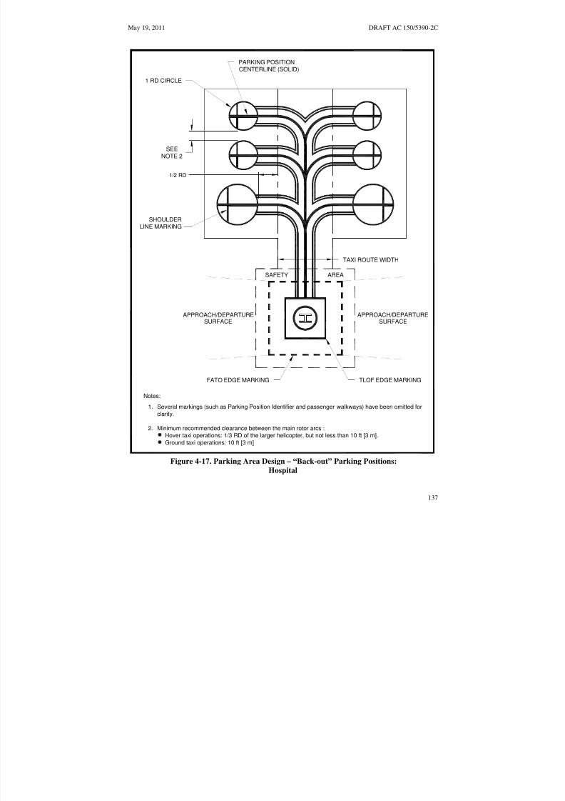
8/3/2019 draft_150_5390_2C
http://slidepdf.com/reader/full/draft15053902c 145/198
May 19, 2011 DRAFT AC 150/5390-2C
PARKING POSITION
CENTERLINE (SOLID)
1 RD CIRCLE
SEENOTE 2
1/2 RD
SHOULDERLINE MARKING
TAXI ROUTE WIDTH
SAFETY AREA
APPROACH/DEPARTURE APPROACH/DEPARTURESURFACE SURFACE
FATO EDGE MARKING TLOF EDGE MARKING
Notes:
1. Several markings (such as Parking Position Identifier and passenger walkways) have been omitted forclarity.
2. Minimum recommended clearance between the main rotor arcs :Hover taxi operations: 1/3 RD of the larger helicopter, but not less than 10 ft [3 m]. Ground taxi operations: 10 ft [3 m]
Figure 4-17. Parking Area Design – “Back-out” Parking Positions:
Hospital
137
8/3/2019 draft_150_5390_2C
http://slidepdf.com/reader/full/draft15053902c 146/198
1
R D
P
A R
K I N G C
I R
C L
E
R O
T O
R L I
T A
A R
C
DRAFT AC 150/5390-2C May 19, 2011
1/3 RDSECURITY FENCE
PASSENGER WALKWAY
1/3 RD
1/3 RD OF LARGESTDESIGN HELICOPTER
CAUTION SIGNAT GATE
LARGEST D THEPARKING POSITION
WILL ACCOMMODATE
PARKING POSITIONIDENTIFIER
(LETTER OR NUMBER)
TDPC MARKING
Notes:
1. The design of these parking positions is based on the 2. Minimum recommended clearance between theunderstanding that the helicopter may pivot about the tail rotor arcs:mast prior to exiting the parking position. Hover taxi operations: 1/3 RD of the larger
helicopter but not less than 10 ft [3 m]Ground taxi operations: 10 ft [3 m]
Figure 4-18. “Turn-around” Helicopter Parking Position Marking:
Hospital
138
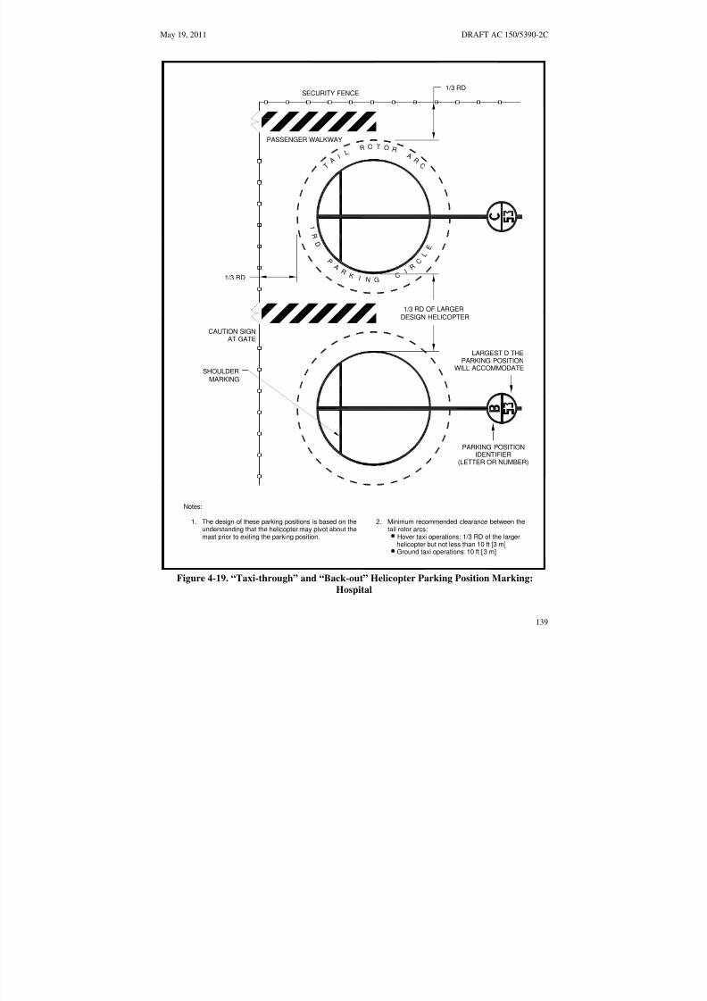
8/3/2019 draft_150_5390_2C
http://slidepdf.com/reader/full/draft15053902c 147/198
1
R D
P
A R
K I N G C
I R
C L
E
R O
T O
R L I
T A
A R
C
May 19, 2011 DRAFT AC 150/5390-2C
1/3 RDSECURITY FENCE
PASSENGER WALKWAY
1/3 RD
1/3 RD OF LARGERDESIGN HELICOPTER
CAUTION SIGNAT GATE
LARGEST D THEPARKING POSITION
WILL ACCOMMODATESHOULDER
MARKING
PARKING POSITIONIDENTIFIER
(LETTER OR NUMBER)
Notes:
1. The design of these parking positions is based on the 2. Minimum recommended clearance between theunderstanding that the helicopter may pivot about the tail rotor arcs:mast prior to exiting the parking position. Hover taxi operations: 1/3 RD of the larger
helicopter but not less than 10 ft [3 m]Ground taxi operations: 10 ft [3 m]
Figure 4-19. “Taxi-through” and “Back-out” Helicopter Parking Position Marking:
Hospital
139

8/3/2019 draft_150_5390_2C
http://slidepdf.com/reader/full/draft15053902c 148/198
DRAFT AC 150/5390-2C May 19, 2011
TDPC MARKING(USE WITH TURN-AROUND
PARKING ONLY)INNER DIAMETER =1/2 D OF DESIGN HELICOPTER18 IN. [45.7 CM] WIDEYELLOW STRIPE
PASSENGER WALKWAY
IN BLACK AND WHITE PAINT
SHOULDER LINE(USE WITH TAXI-THROUGH
AND BACK-OUT ONLY)6 IN [15 CM] WIDEYELLOW LINE
CENTERLINE12 IN [30 CM] WIDE
YELLOW LINE
10 FT [3 M]OUTER DIAMETER CIRCLE
6 IN [15 CM] WIDE
YELLOW LINE
6 IN [15 CM]WIDE STRIPE
YELLOW LINE
1 RD CIRCLE
6 IN [15 CM] WIDE
YELLOW LINE
PARKING POSITION WEIGHTLIMITATION (IF APPLICABLE)IN 3 FT [0.9 M] HIGH CHARACTERS
PARKING POSITION IDENTIFIER(LETTER OR NUMBER)IN 3 FT [0.9 M] HIGH CHARACTERS
LARGEST D THE PARKINGPOSITION WILL ACCOMMODATEIN 3 FT [0.9 M] HIGH CHARACTERS
Figure 4-20. Parking Position Identification, Size, and Weight Limitations:
General Aviation
140

8/3/2019 draft_150_5390_2C
http://slidepdf.com/reader/full/draft15053902c 149/198
May 19, 2011 DRAFT AC 150/5390-2C
(3) “Taxi-through” parking positions are illustrated in Figure 4-15 on page 135. When this designis used for parking positions, the heliport owner and operator should take steps to ensure that all pilots areinformed that “turn-around” or “back-up” departures from the parking position are not permitted.
(4) “Turn-around” parking positions are illustrated in Figure 4-17.
(5) “Back-out” parking positions are illustrated in Figure 4-17 on page 137. When this design isused for parking positions, the adjacent taxiway should be designed to accommodate hover taxioperations so that the width of the taxiway will be adequate to support “back-out” operations.
c. Parking Pads. If the entire area of the parking position is not paved, the smallest dimension of apaved parking pad must be a minimum of two times the maximum dimension (length or width, whicheveris greater) of the undercarriage or the RD, whichever is less, of the largest helicopter that will use thisparking position. The parking pad should be placed in the center of the parking position circle.
d. Walkways. At parking positions, marked walkways should be provided where practicable. Thepavement should be designed to drain away from walkways.
e. Fueling. Helicopter fueling is typically accomplished with the use of a fuel truck or the use of aspecific fueling area with stationary fuel tanks.
(1) Systems for storing and dispensing fuel must conform to Federal, state, and localrequirements for petroleum handling facilities. Guidance is found in AC 150/5230-4, Aircraft Fuel
Storage, Handling, and Dispensing on Airports, and National Fire Protection Association (NFPA) 403,Standard for Aircraft Rescue and Fire Fighting Services at Airports, and NFPA 418, Standards for
Heliports.
(2) Fueling locations must be designed and marked to minimize the potential for helicopters tocollide with the dispensing equipment. Fueling areas must be designed so there is no object tall enough tobe hit by the main or tail rotor blades within a distance of RD from the center point of the position where
the helicopter would be fueled (providing 0.5 rotor diameter tip clearance from the rotor tips). If this isnot practical at an existing facility, long fuel hoses should be installed.
(3) Lighting. The fueling area should be lighted if night fueling operations are contemplated.Care should be taken to ensure that any light poles do not constitute an obstruction hazard.
f. Tiedowns. Recessed tiedowns may be installed to accommodate extended or overnight parking of based or transient helicopters. If tiedowns are provided, they must be recessed so as not to be a hazard tohelicopters. Caution should be exercised to ensure that any depression associated with the tiedowns is of adiameter not greater than 1/2 the width of the smallest helicopter landing wheel or landing skidanticipated to be operated on the heliport surface. In addition, tiedown chocks, chains, cables and ropesshould be stored off the heliport surface to avoid fouling landing gear. Guidance on recessed tiedowns canbe found in AC 20-35, Tiedown Sense.
413. HELIPORT MARKERS AND MARKINGS. Markers and/or surface markings should identifythe facility as a heliport. Surface markings may be paint, reflective paint, reflective markers, or preformedmaterial. Lines/markings may be outlined with a 6-inch wide (15 cm) line of a contrasting color toenhance conspicuity. Markings that define the edges of a TLOF, FATO, taxiway or apron are placedwithin the limits of those areas. The following markers and markings are used.
141

8/3/2019 draft_150_5390_2C
http://slidepdf.com/reader/full/draft15053902c 150/198
DRAFT AC 150/5390-2C May 19, 2011
a. Hospital Heliport Identification Marking. The identification marking identifies thelocation as a hospital heliport, marks the TLOF and provides visual cues to the pilot.
(1) Standard Hospital Heliport Identification Symbol. The TLOF is marked with a red“H” in a white cross. The “H” is oriented on the axis of the preferred approach/departure path. A bar maybe placed under the “H” when it is necessary to distinguish the preferred approach/departure direction.
The proportions and layout of the standard hospital heliport identification symbol are illustrated in Figure4-21 on page 143.
(2) Alternative Marking. As an alternative to the standard marking, a red “H” with a white6 inch (15 cm) wide border within a red cross with a 12 inch (30 cm) wide white border and asurrounding red TLOF may be used. Where it is impractical for the whole TLOF to be painted red, theminimum dimension (length, width, or diameter) of the outer red area is equal to the RD of the designhelicopter but not less than 40 feet (12.2 m). Figure 4-22 on page 144 illustrates this alternative marking.
(3) Winter Operations. In winter weather at a heliport with a dark TLOF surface, themarking in Figure 4-22 on page 144 will absorb more heat from the sun and more readily melt residualice and snow. In contrast, the white area in Figure 4-21 on page 143 is more likely to be icy during winter
weather. Consequently, in areas that experience ice and snow, the markings in Figure 4-22 on page 144should be used for unheated TLOFs.
b. TLOF Markings.
(1) TLOF Perimeter Marking. It is recommended that the TLOF perimeter be defined withmarkers and/or lines. See paragraph 407 above and
(2) on page 119 for guidance on increasing the size of the safety area if the TLOF perimeteris not marked.
(a) Paved TLOFs. The perimeter of a paved or hard surfaced TLOF is defined with a
continuous, 12-inch-wide (30 cm), white line (see Figure 4-23 on page 145).
(b) Unpaved TLOFs. The perimeter of an unpaved TLOF is defined with a series of 12inch-wide (30 cm), flush, in-ground markers, each approximately 5 feet (1.5 m) in length with end-to-endspacing of not more than 6 inches (15 cm). (See Figure 4-24 on page 146.)
(3) Touchdown/Positioning Circle (TDPC) Marking. A touchdown/positioning circlemarking is used to provide guidance to allow a pilot to touch down in a specific position on pavedsurfaces. When the pilot’s seat is over the marking, the undercarriage will be inside the load-bearing area,and all parts of the helicopter will be clear of any obstacle by a safe margin. A TDPC marking is a yellowcircle with an inner diameter of 0.5 D and a line width of 18 in (0.5 m). A TDPC marking is located in thecenter of a TLOF (see Figure 4-21 on page 143, Figure 4-22 on page 144, and Figure 4-23 on page 145).
142

8/3/2019 draft_150_5390_2C
http://slidepdf.com/reader/full/draft15053902c 151/198
May 19, 2011 DRAFT AC 150/5390-2C
30 FT [10 M]
10 FT [3 M]
30 FT [10 M] 10 FT [3 M]
TOUCHDOWN/POSITION CIRCLEOUTER DIAMETER = 1/2 D OF
DESIGN HELICOPTER18 IN [45 CM] WIDE
YELLOW STRIPE
Notes:
1. Standard TLOF perimeter stripe of 12 in [30 cm]. See figure 4-24 for "H", touchdown/ Figure 4-25positioning, overall length and weight limitation box dimensions.
2. The standard hospital identification is a redH
within a white cross.
3. An option may be a red H within a white cross surrounded by a 12 in [30 cm] wide redborder (not illustrated).
4. The area outside of the cross may be colored red.
Figure 4-21. Standard Hospital Heliport Identification Symbols:
Hospital
143

8/3/2019 draft_150_5390_2C
http://slidepdf.com/reader/full/draft15053902c 152/198
DRAFT AC 150/5390-2C May 19, 2011
12 IN [30 CM]STRIPE
30 FT [10 M]
30 FT [10 M] 10 FT [3 M]
10 FT [3 M]STRIPE6 IN [15 CM]
Notes:
Figure 4-25position, overall length and weight limitation box dimensions.1. Standard TLOF perimeter stripe of 12 in [30 cm]. See figure 4-24 for "H", touchdown
Figure 4-22. Alternative Hospital Heliport Identification Symbols: Hospital
144

8/3/2019 draft_150_5390_2C
http://slidepdf.com/reader/full/draft15053902c 153/198
4-24
May 19, 2011 DRAFT AC 150/5390-2C
DETAIL A FATO MARKING DETAIL
5 FT [1.5 M]
APPROACH/DEPARTURE SURFACE
APPROACH/DEPARTURE SURFACE
12 IN [30 CM]
PAINTED TLOF EDGE MARKING
IN GROUND FATO EDGE MARKING
SAFETY AREA
SEE NOTE 3 AND DETAIL A
SEE NOTE 2
5 FT [1.5 M] MIN
6 FT [2 M] MAX
Notes:
The perimeter of the TLOF and the FATO are marked.1.
2.
3.
5. See Figure for " H", touchdown/position, overall length and weight limitation boxdimensions.
The perimeter of a paved or hard surfaced TLOF is defined with a continuous12 in [30 cm] white line.
Paved FATO perimeters are defined with a 12 in [30 cm] wide dashed line per Detail A.
TDPC
MARKING
4. Unpaved FATO perimeters are defined with a flush in-ground marker per Detail A.
Figure 4-25
Figure 4-23. Paved TLOF/Paved FATO – Paved TLOF/Unpaved FATO – Marking: Hospital
145

8/3/2019 draft_150_5390_2C
http://slidepdf.com/reader/full/draft15053902c 154/198
igure 4-24
DRAFT AC 150/5390-2C May 19, 2011
DETAIL A TLOF FLUSH IN-GROUND MARKING DETAIL
5 FT [1.5 M]12 IN [30 CM]
An unpaved TLOF perimeter is defined with flush in-ground markers per Detail A.
An unpaved FATO perimeter is defined with flush in-ground markers per Detail B.
2.
3.
DETAIL B FATO FLUSH IN-GROUND MARKING DETAIL
UNPAVED TLOF EDGE MARKING
FATO EDGE MARKING
APPROACH/DEPARTURE SURFACE
SAFETY AREA
SEE NOTE 3 AND DETAIL B
12 IN [30 CM]
APPROACH/DEPARTURE SURFACE
SEE NOTE 2 AND DETAIL A
5 FT [1.5 M]
UNPAVED FATO
0 FT [0 M] MIN6 IN [30 CM] MAX
5 FT [1.5 M] MIN6 FT [2 M] MAX
Notes:
The perimeter of the TLOF and FATO are marked.1.
4. See F for " H", touchdown/positioning, overall length, and weight limitation boxdimensions.
TDPCMARKING
Figure 4-25
Figure 4-24. Unpaved TLOF/Unpaved FATO – Marking: Hospital
146

8/3/2019 draft_150_5390_2C
http://slidepdf.com/reader/full/draft15053902c 155/198
May 19, 2011 DRAFT AC 150/5390-2C
(4) TLOF Size and Weight Limitations. The TLOF is marked to indicate the length andweight of the largest helicopter for which it is designed, as shown in Figure 4-25 on page 148. Thesemarkings are contained in a box that is located in the lower right-hand corner of the TLOF, or on theright-hand side of the “H” of a circular TLOF, when viewed from the preferred approach direction. Thebox is 9 feet square (2.7m), or ), or for TLOFs less than 24 feet (7.3m), no less than 5 feet (1.5m) square.The numbers are 3 feet (0.9 m) high or, for smaller heliports, no less than 20 inches (51 cm). If necessary,
this marking may interrupt the Touchdown/Positioning Circle marking but may not extend to within thecircle, except for circular TLOFs. (See Appendix C on page 187.) The numbers are black with a whitebackground. This marking is optional at a TLOF with a turf surface.
(a) TLOF Size Limitation. This number is the length (D) of the largest helicopter forwhich it is designed, as shown in Figure 4-25 on page 148. The marking consists of the letter “D”followed by the dimension in feet. Metric equivalents are not used for this purpose. This marking iscentered in the lower section of the TLOF size/weight limitation box.
(b) TLOF Weight Limitations. If a TLOF has limited weight-carrying capability, it ismarked with the maximum takeoff weight of the design helicopter, in units of thousands of pounds, asshown in Figure 4-25 on page 148. Metric equivalents are not be used for this purpose. This marking is
centered in the upper section of a TLOF size/weight limitation box. If the TLOF does not have a weightlimit, a diagonal line extending from the lower left hand corner to the upper right hand corner, should beadded to the upper section of the TLOF size/weight limitation box.
c. LBA Markings. At PPR heliports, the load bearing area may be increased without acorresponding increase in the length and width or diameter of the FATO. The LBA outside the TLOF ismarked with 12-inch-wide (30 cm) diagonal black and white stripes. See Figure 4-26 for marking details.
d. FATO Markings.
(1) FATO Perimeter Marking. The perimeter of a load-bearing FATO is defined withmarkers and/or lines. The FATO perimeter is not marked if any portion of the FATO is not a load-bearing
surface. In such cases, the TLOF perimeter should be marked (see paragraph 413.b(1) above.)
(a) Paved FATOs. The perimeter of a paved load-bearing FATO is defined with a 12inch-wide (30 cm) dashed white line. The corners of the FATO are defined, and the perimeter markingsegments are 12 inches in width, approximately 5 feet (1.5 m) in length, and with end-to-end spacing of approximately 5 feet (1.5 m). (See Figure 4-23 on page 145.)
(b) Unpaved FATOs. The perimeter of an unpaved load-bearing FATO is defined with12-inch-wide (30 cm), flush, in-ground markers. The corners of the FATO are defined, and the rest of theperimeter markers are approximately 5 feet (1.5 m) in length, and have end-to-end spacing of approximately 5 feet (1.5 m). (See Figure 4-23 on page 145 and Figure 4-24 on page 146.)
e. Flight Path Alignment Guidance Marking. An optional flight path alignment guidancemarking consists of one or more arrows to indicate the preferred approach/departure direction(s). It ismarked on the TLOF, FATO and/or safety area surface as shown in Figure 4-10 on page 127. The shaft of the arrow(s) is 18 in. (50 cm) in width and at least 10 feet (3 m) in length. When combined with a flightpath alignment guidance lighting system described in paragraph 414.e below, it takes the form shown inFigure 4-10 on page 127, which includes scheme for marking the arrowheads. The markings must be in acolor which provides good contrast against the background color of the surface on which they are marked.In the case of a flight path limited to a single approach direction or a single takeoff direction, the arrow
147

8/3/2019 draft_150_5390_2C
http://slidepdf.com/reader/full/draft15053902c 156/198
DRAFT AC 150/5390-2C May 19, 2011
marking is unidirectional. In the case of a heliport with only a bidirectional approach/takeoff flight pathavailable, the arrow marking is bidirectional.
ALTERNATE MARKING WITH
DETAIL B
SEE NOTE 2
SEE NOTE 3
NO WEIGHT RESTRICTIONS
10'-0"[3 M]
2'-0"[60 CM]
TLOF SIZE/WEIGHTLIMITATION 'BOX'
DETAIL AHELIPORT INDENTIFICATION
SYMBOL
SEE DETAIL B
SEE DETAIL A
TOUCHDOWN/POSITION CIRCLE
OUTER DIAMETER = 1/2 D OFDESIGN HELICOPTER18 IN [45 CM] WIDE
YELLOW STRIPE
NO WEIGHT LIMIT
Notes:
See Appendix D for the form and proportion of the numbers used in the TLOF Size and
"10" indicates the maximum takeoff weight (10,000 lbs [4,535 kg]) of the TLOF design
"D46" indicates the overall length of the largest helicopter (46 ft [14.0 M]) for which the
1.
2.
3.
Limitation Box.
TLOF is designed.
helicopter, in units of thousands of pounds [kilograms].
6'-8" [1.82 M]
1'-0" [30 CM] 5 IN[12.7 CM]
9 FT [2.8 M]SQUARE
Figure 4-25. TLOF Size and Weight Limitations: Hospital
148

8/3/2019 draft_150_5390_2C
http://slidepdf.com/reader/full/draft15053902c 157/198
May 19, 2011 DRAFT AC 150/5390-2C
Notes:
Expanded load bearing markings begin flush with TLOF edge markings and end1.
2. Expanded Load bearing markings are defined with 12 in [30 cm] wide black andwhite stripes on a 45° angle.
TLOF EDGE MARKING
FATO EDGE MARKING
at the edge of the LBA.
FLUSH FATO EDGE LIGHTSLBA
Figure 4-26. LBA Marking: Hospital
149

8/3/2019 draft_150_5390_2C
http://slidepdf.com/reader/full/draft15053902c 158/198
DRAFT AC 150/5390-2C May 19, 2011
f. Taxi Route and Taxiway Markings.
(1) Paved Taxiway Markings. The centerline of a paved taxiway is marked with acontinuous 6-inch (15 cm) yellow line. Both edges of the paved portion of the taxiway are marked withtwo continuous 6- inch wide (15 cm) yellow lines spaced 6 inches (15 cm) apart. Figure 4-12 on page 130illustrates taxiway centerline and edge markings.
(2) Unpaved Taxiway Markings. Edge markers are used to provide strong visual cues topilots. Edge markers may be either raised or in-ground flush markers. They are longitudinally spaced atapproximately 15-foot (5 m) intervals on straight segments and at approximately 10-foot (3 m) intervalson curved segments. Figure 4-13 on page 131 and Figure 4-14 on page 132 illustrate taxiway edgemarkings.
(a) Raised-edge markers are blue, 4 inches (10 cm) in diameter, and 10 inches (25 cm)high, as illustrated in Figure 4-13 on page 131.
(b) In-ground, flush edge markers are yellow, 12 inches (30 cm) wide, andapproximately 5 feet (1.5 m) long.
(3) Raised Edge Markers in Grassy Areas. Raised edge markers are sometimes obscuredby tall grass. The heliport operator should address this problem with a 12-inch diameter (30 cm) diameterconcrete pad or a solid material disk around the pole supporting the raised marker.
(4) Taxiway to Parking Position Transition Requirements. For paved taxiways andparking areas, taxiway centerline markings continue into parking positions and become the parkingposition centerlines.
g. Parking Position Markings. If a hospital heliport has a parking position, the followingrecommendations apply.
(1) Paved Parking Position Identifications. Parking position identifications (numbers orletters) are marked if there is more than one parking position. These markings are yellow characters 3 feet(0.9 m) high. (See Figure 4-20 on page 140 and Figure C–1 on page 187).
(2) Rotor Diameter Circle. A 6-inch-wide (15 cm), solid yellow line defines a circle of therotor diameter of the largest helicopter that will park at that position. In paved areas, this is a painted line(See Figure 4-20 on page 140). In unpaved areas, this line is defined by a series of flush markers, 6 inches(15 cm) in width, a maximum of 5 feet (1.5 m) in length, and with end-to-end spacing of approximately 5feet (1.5 m).
h. Touchdown/Positioning Circle (TDPC) Marking. An optional touchdown/positioningcircle marking provides guidance to allow a pilot to touch down in a specific position on paved surfaces.When the pilot’s seat is over the marking, the undercarriage will be inside the load-bearing area, and allparts of the helicopter will be clear of any obstacle by a safe margin. A TDPC marking is a yellow circlewith an inner diameter of 0.5 D and a line width of 18 in (0.5 m). A TDPC marking is located in thecenter of a parking area. A TDPC marking is recommended for “turn-around” parking areas. See Figure4-20 on page 140 and Figure 4-18 on page 138.
i. Maximum Length Marking. This marking on paved surfaces indicates the D of the largesthelicopter that the position is designed to accommodate (e.g., 40). This marking is in yellow characters atleast 3 feet (0.9 m) high. (See Figure 4-20 on page 140 and Figure C–1 on page 187.)
150

8/3/2019 draft_150_5390_2C
http://slidepdf.com/reader/full/draft15053902c 159/198
May 19, 2011 DRAFT AC 150/5390-2C
j. Parking Position Weight Limit. If a paved parking position has a weight limitation, it isstated in units of 1,000 pounds as illustrated in Figure 4-20 on page 140. (A 4 indicates a weight-carryingcapability of up to 4,000 pounds. Metric equivalents are not be used for this purpose.) This markingconsists of yellow characters 3 feet (0.9 m) high. A bar may be placed under the number to minimize thepossibility of being misread. (See Figure 4-18 on page 138 and Figure C–1 on page 187).
k. Shoulder Line Markings. Optional shoulder line markings are used for paved parking areas(See Figure 4-15 on page 135) to ensure safe rotor clearance. A 6-inch-wide (15 cm) solid yellowshoulder line, perpendicular to the centerline and extending to the RD marking, is located so it is underthe pilot’s shoulder such that the main rotor of the largest helicopter for which the position is designedwill be entirely within the rotor diameter parking circle (See Figure 4-20 on page 140). Use 0.25D fromthe center of parking area to define the location of shoulder line. A shoulder line marking isrecommended for “taxi through” and “back-out” parking areas.
l. Walkways. Figure 4-20 on page 140 illustrates one marking scheme.
m. Closed Heliport. All markings of a permanently closed heliport, FATO, or TLOF should beobliterated. If it is impractical to obliterate markings, a yellow “X” should be placed over the “H”, as
illustrated in Figure 4-27 below. The yellow “X” must be large enough to ensure early pilot recognitionthat the heliport is closed. The wind cone(s) and other visual indications of an active heliport must also beremoved.
n. Marking Sizes. See Appendix C on page 187 for guidance on the proportions of paintednumbers.
WIND CONE REMOVED
Notes:
1. A yellow "X" marking should be painted over the "H" when removal or obliteration of theheliport markings is impractical.
Figure 4-27. Marking a Closed Heliport:
Hospital
151

8/3/2019 draft_150_5390_2C
http://slidepdf.com/reader/full/draft15053902c 160/198
DRAFT AC 150/5390-2C May 19, 2011
414. HELIPORT LIGHTING. For night operations, the heliport must be lighted with FATO and /orTLOF perimeter lights as described below.
a. TLOF Perimeter Lights.
(1) Green lights meeting the requirements of FAA Airports Engineering Brief 87, Heliport
Lighting3 are used to define the TLOF perimeter. If only the TLOF is load bearing, flush lights arerecommended, but raised green omnidirectional lights may be used. A minimum of three light fixtures isrequired per side of a square or rectangular TLOF. A light is located at each corner, with additional lightsuniformly spaced between the corner lights. It is recommended each side comprise an odd number of lights, thereby including lights along the centerline of the approach. To define a circular TLOF, an evennumber of lights, with a minimum of eight, are uniformly spaced. The maximum spacing of lights is 25feet (7.6 m). Flush lights are located within 1 foot (30 cm) (inside or outside) of the TLOF perimeter.Raised lights should be located outside and within 10 feet (3m) of the edge of the TLOF and should notpenetrate a horizontal plane at the TLOF elevation by more than 2 inches (5 cm). In areas where it snows,the outside edge is the preferred location, as lights on the outside edge of the TLOF are prone to breakageduring snow removal. Figure 4-28 on page 153 and Figure 4-30 on page 155 illustrate these lights.
(2) Elevated TLOF Perimeter Lights. Raised, omnidirectional lights meeting therequirements of EB 87 may be used, located on the outside edge of the TLOF or the outer of the safetynet, as shown in Figure 4-29 on page 154. In areas where it snows, the outer edge of the safety net is thepreferred location, as lights on the outside edge of the TLOF are prone to breakage during snow removal.Lighting on the outer edge of the safety net also provides better visual cues to pilots at a distance from theheliport since it outlines a larger area. The raised lights must not penetrate a horizontal plane at the TLOFelevation by more than 2 inches (5 cm).
b. Load-bearing FATO Perimeter Lights. Green lights meeting the requirements of EB 87define the perimeter of a load bearing FATO. The FATO perimeter is not lighted if any portion of theFATO is not a load-bearing surface. A minimum of three flush or raised light fixtures is required per sideof a square or rectangular FATO. A light is located at each corner, with additional lights uniformly spaced
between the corner lights. It is recommended each side comprise an odd number of lights, therebyincluding lights along the centerline of the approach. To define a circular FATO, an even number of lights, with a minimum of eight, are uniformly spaced. The maximum spacing of lights is 25 feet (7.6 m).Flush lights are located within 1 foot (30 cm) (inside or outside) of the FATO perimeter (See Figure 4-28on page 153 and Figure 4-30 on page 155.). In areas where it snows in the winter, the outside edge is thepreferred location, as lights on the inside edge of the FATO are prone to breakage during snow removal.A square or rectangular pattern of FATO perimeter lights are recommended even if the TLOF is circular.At a distance during nighttime operations, a square or rectangular pattern of FATO perimeter lightsprovides the pilot with better visual cues than a circular pattern. In the case of an elevated FATO with asafety net, the perimeter lights are mounted in a similar manner as discussed in paragraph 414.a(2) above.If raised FATO perimeter lights are used, they should be no more than 8 inches (20 cm) high, and located10 feet (3 m) from the FATO perimeter.
c. Floodlights. If ambient light does not adequately illuminate markings for night operations,floodlights should be used to illuminate the TLOF, the FATO, and/or the parking area. To eliminate theneed for tall poles, these floodlights may be mounted on adjacent buildings. Care should be taken,however, to place floodlights clear of the TLOF, the FATO, the safety area, and the approach/departure
3 As of the date of this draft, EB 87 has not been completed. Guidance on heliport lighting will be published as soonas possible.
152

8/3/2019 draft_150_5390_2C
http://slidepdf.com/reader/full/draft15053902c 161/198
May 19, 2011 DRAFT AC 150/5390-2C
surfaces, and transitional surfaces. Care should be taken to ensure that floodlights and their associatedhardware do not constitute an obstruction hazard. Floodlights should be aimed down and provideadequate illumination on the surface. Floodlights that might interfere with pilot vision during takeoff andlandings should be capable of being turned off by pilot control or at pilot request.
5 LANDING DIRECTION LIGHTS (OPTIONAL)SEE FIGURE 4-29 FOR DETAILSFigure 4-31
LIGHTED WIND CONE
PREFERRED APPROACH CL
FLUSH FATO EDGE LIGHTS
FLUSH TLOF EDGE LIGHTS
1 FT [30 CM]
FLUSH IN-PAVEMENT LIGHT DETAIL
Notes:
1. Flush FATO and TLOF perimeter lights may be installed inside or outside within 1 ft [30 cm]the FATO and TLOF respective perimeters.
2. Overall length and weight limitation box marking omitted for clarity.
Figure 4-28. Flush TLOF/FATO Perimeter Lighting:
Hospital
153

8/3/2019 draft_150_5390_2C
http://slidepdf.com/reader/full/draft15053902c 162/198
DRAFT AC 150/5390-2C May 19, 2011
SAFETY NET
B
NOT LESS THAN 5 FT [1.5 M]
NOT MORE THAN2 IN [5 CM]
12 IN [30 CM]
AC
(SURROUNDINGTHE TLOF or LBA)
Three possible locations for TLOF/LBA edge lighting:
Flush edge fixtures
Omni-directional light, mounted off TLOF/LBA edge
Omni-directional light, mounted off outer edge of safety net (preferred locationin snow areas)
A
B
C
FALL PROTECTION:
RECOMMENDED IFABOVE 30 IN [0.8 M]
REQUIRED IFABOVE 4 FT [1.2 M]
Figure 4-29. Elevated TLOF, Safety Net and Lighting Heliport Partial Elevation: Hospital
154

8/3/2019 draft_150_5390_2C
http://slidepdf.com/reader/full/draft15053902c 163/198
May 19, 2011 DRAFT AC 150/5390-2C
5 LANDING DIRECTION LIGHTS (OPTIONAL)
SEE FIGURE 4-29 FOR DETAILSFi ure 4-31
LIGHTED WIND CONE
PREFERRED APPROACH CL
SEE NOTE 2
RAISED FATO OMNI-DIRECTIONAL
LIGHTS
FLUSH TLOF EDGE LIGHTS
Notes:
1. Flush TLOF perimeter lights may be installed inside or outside within 1 ft [30 cm] of the FATOand TLOF respective perimeters.
2. Raised FATO lights may be installed 10 ft [3 m] outside the FATO perimeter.
3. Overall length and weight limitation box marking omitted for clarity.
Figure 4-30. Flush TLOF and Raised FATO Perimeter Lighting:
Hospital
155

8/3/2019 draft_150_5390_2C
http://slidepdf.com/reader/full/draft15053902c 164/198
DRAFT AC 150/5390-2C May 19, 2011
d. Landing Direction Lights. Landing direction lights are an optional feature to be installedwhen it is necessary to provide directional guidance. Landing direction lights are a configuration of fivewhite, omnidirectional lights meeting the standards of EB 87, on the centerline of the preferredapproach/departure path. These lights are spaced at 15-foot (5 m) intervals beginning at a point not lessthan 20 feet (6 m) and not more than 60 feet (18 m) from the TLOF perimeter and extending outward inthe direction of the preferred approach/departure path, as illustrated in Figure 4-31 on 157.
e. Flight Path Alignment Lights. Flight path alignment lights meeting the requirements of Engineering Brief 87 are optional. They are placed in a straight line along the direction of approachand/or departure flight paths. The lights may extend across the TLOF, FATO, safety area or any suitablesurface in the immediate vicinity of the FATO or safety area. Three or more white lights are spaced at(1.5 m) to (3.0 m). See Figure 4-10 on page 127.
f. Taxiway and Taxi Route Lighting.
(1) Taxiway Centerline Lights. Taxiway centerlines are defined with flush bidirectionalgreen lights meeting the standards of AC 150/5345-46 for type L-852A (straight segments) or L-852B(curved segments). These lights are spaced at maximum 50-foot (15 m) longitudinal intervals on straight
segments and at maximum 25-foot (7.5 m) intervals on curved segments, with a minimum of four lightsneeded to define the curve. Taxiway centerline lights may be uniformly offset no more than two feet toease painting the taxiway centerline. Green retroreflective markers meeting requirements for type IImarkers in AC 150/5345-39, Specification for L-853, Runway and Taxiway Retroreflective Markers, maybe used in lieu of the L-852A or L-852B lighting fixtures.
(2) Taxiway Edge Lights. Omnidirectional blue lights are used to light the edges of ataxiway. Blue retroreflective markers may be used to identify the edges of the taxiway in lieu of lights.When retroreflective markers are used, they must be no more than 8 inches (20 cm) tall.
(a) Straight Segments. Lights are spaced at 50 feet (15.2 m) longitudinal intervals onstraight segments.
(b) Curved Segments. Curved taxiway edges require shorter spacing of edge lights. Thespacing is determined based on the radius of the curve. The applicable spacing for curves is shown inFigure 17 of AC 150/5340-30, Design and Installation Detail for Airport Visual Aids. The taxiway edgelights are uniformly spaced. Curved edges of more than 30 degrees from point of tangency (PT) of thetaxiway section to PT of the intersecting surface must have at least three edge lights. For radii not listed inFigure 17 determine spacing by linear interpolation.
(c) Paved Taxiways. Flush lights must meet the standards of AC 150/5345-46 for typeL-852T.
(d) Unpaved Taxiways. Raised lights must meet the standards of AC 150/5345-46 fortype L-861T . The lateral spacing for the lights or reflectors is equal to the RD of the design helicopter,but not more than 35 feet.
156

8/3/2019 draft_150_5390_2C
http://slidepdf.com/reader/full/draft15053902c 165/198
May 19, 2011 DRAFT AC 150/5390-2C
FATO
TLOF
NOT LESS THAN20 FT [6 M]
NOR MORE THAN60 FT [18 M]
4 EQUAL SPACES@ 15 FT [4.6 M]= 60 FT [18.4 M]
Legend:
Omni-directional white lights Note: Not drawn to scale
Figure 4-31. Landing Direction Lights:
Hospital
157

8/3/2019 draft_150_5390_2C
http://slidepdf.com/reader/full/draft15053902c 166/198
DRAFT AC 150/5390-2C May 19, 2011
g. Heliport Identification Beacon. A heliport identification beacon is optional equipment. Itshould be installed when it is needed to aid the pilot in visually locating the heliport. When installed, thebeacon, flashing white/green/yellow at the rate of 30 to 45 flashes per minute, is located on or close to theheliport. Guidance on heliport beacons is found in AC 150/5345-12, Specification for Airport and
Heliport Beacon. It is permissible for the beacon to be pilot controllable such that it is “on” only whenrequired.
415. MARKING AND LIGHTING OF DIFFICULT-TO-SEE OBJECTS. Unmarked wires,antennas, poles, cell towers, and similar objects are often difficult to see, even in the best daylightweather, in time for a pilot to successfully take evasive action. While pilots can avoid such objects duringen route operations by flying well above them, approaches and departures require operations near theground where obstacles may be a factor. This paragraph discusses the marking and lighting of objectsnear, but outside and below the approach/departure surface. Guidance on marking and lighting objects iscontained in AC 70/7460-1, Obstruction Marking and Lighting.
a. Airspace. If difficult-to-see objects penetrate the object identification surfaces illustrated inFigure 4-32 on page 159, these objects should be marked to make them more conspicuous. If operationsare conducted at a heliport between dusk and dawn, these difficult-to-see objects should be lighted.
Guidance on marking and lighting objects is contained in AC 70/7460-1, Obstruction Marking and Lighting. The object identification surfaces in Figure 4-32 on page 159 can also be described as follows:
(1) In all directions from the safety area, except under the approach/departure paths, theobject identification surface starts at the safety area perimeter and extends out horizontally for a distanceof 100 feet (30.5 m).
(2) Under the approach/departure surface, the object identification surface starts from theoutside edge of the FATO and extends horizontally out for a distance of 800 feet (244 m). From thispoint, the object identification surface extends out for an additional distance of 3,200 feet (975 m) whilerising on an 8:1 slope (8 units horizontal in 1 unit vertical). From the point 800 feet (244 m) from theFATO perimeter, the object identification surface is 100 feet (30.5 m) beneath the approach/departure
surface.
(3) The width of the safety surface increases as a function of distance from the safety area.From the safety area perimeter, the object identification surface extends laterally to a point 100 feet (30.5m) outside the safety area perimeter. At the upper end of the surface, the object identification surfaceextends laterally 200 feet (61 m) on either side of the approach/departure path.
b. Shielding of Objects. If there are a number of obstacles close together, it may not benecessary to mark all of them if they are shielded. To meet the shielding guidelines an object must beshielded by existing structures of a permanent and substantial character or by natural terrain ortopographic features of equal or greater height, and must be located in the congested area of a city, town,or settlement where it is evident beyond all reasonable doubt that the structure so shielded will not
adversely affect safety in air navigation. Additional guidance on this topic may be found in 14 CFR part77.9, Construction or alteration requiring notice.
c. Heliport maintenance and servicing equipment, as well as other objects used in the airsideoperational areas, should be made conspicuous with paint, reflective paint, reflective tape, or otherreflective markings. Reference AC 150/5210-5, Painting, Marking, and Lighting of Vehicles Used on an
Airport .
158
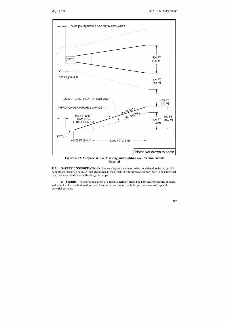
8/3/2019 draft_150_5390_2C
http://slidepdf.com/reader/full/draft15053902c 167/198
May 19, 2011 DRAFT AC 150/5390-2C
( 8 : 1 S L O
P E )APPROACH/DEPARTURE SURFACE
( 8 : 1 S L O
P E )
OBJECT IDENTIFICATION SURFACE
FATO
400 FT
[122M]
100 FT[30 M]
500 FT[152 M]
3,200 FT [975 M]
500 FT[152 M]
100 FT [30 M]FROM EDGE
OF SAFETY AREA
100 FT [30 M] FROM EDGE OF SAFETY AREA
100 FT [30 M] R
Note: Not drawn to scale
200 FT
[61 M]
Figure 4-32. Airspace Where Marking and Lighting are Recommended: Hospital
416. SAFETY CONSIDERATIONS. Some safety enhancements to be considered in the design of aheliport are discussed below. Other areas such as the effects of rotor downwash may need to be addressedbased on site conditions and the design helicopter.
a. Security. The operational areas of a hospital heliport should be kept clear of people, animals,and vehicles. The method used to control access depends upon the helicopter location and types of potential intruders.
159

8/3/2019 draft_150_5390_2C
http://slidepdf.com/reader/full/draft15053902c 168/198
DRAFT AC 150/5390-2C May 19, 2011
(1) Safety Barrier. At ground-level hospital heliports, one method is to erect a safety barrieraround the helicopter operational areas. This barrier may take the form of a fence, wall, or hedge. It mustbe no closer to the operating areas than the outer perimeter of the safety area. Barriers must not penetrateany approach/departure (primary or transitional) surface. Thus, in the vicinity of the approach/departurepaths, the barrier may need to be well outside the outer perimeter of the safety area.
(2) Any barrier must be high enough to present a positive deterrent to persons inadvertentlyentering an operational area and yet low enough to be non-hazardous to helicopter operations.
(3) Access. At some locations, it may be appropriate to restrict access to airside areasthrough controlled entryways. Entryways should display a cautionary sign similar to that illustrated inFigure 4-33 on page 161. Hospital heliport operators may choose to secure their operational areas via theuse of security guards and a mixture of fixed and movable barriers.
b. Rescue and Fire-Fighting Services. Heliports must meet State and local rescue and fire-fighting regulations. A fire hose cabinet or extinguisher must be provided at each access gate/door andeach fueling location. At elevated TLOFs, fire hose cabinets, fire extinguishers, and other fire-fightingequipment must be located adjacent to, but below the level of, the TLOF. Information is available in
NFPA 418, Standards for Heliports, and NFPA 403, Standard for Aircraft Rescue and Fire-FightingServices at Airports. NFPA standards are available at National Fire Protection Association web site athttp://www.nfpa.org.
c. Communications. A Common Traffic Advisory Frequency (CTAF) radio may be used toprovide arriving helicopters with heliport and traffic advisory information but may not be used to controlair traffic. The Federal Communications Commission (FCC) should be contacted for information onCTAF licensing.
d. Weather Information. An automated weather observing system (AWOS) measures andautomatically broadcasts current weather conditions at the heliport site. When an AWOS is installed, itmust be located at least 100 feet (30 m) and not more than 700 feet (213 m) from the TLOF. Locate the
AWOS so its instruments will not be affected by rotor wash from helicopter operations. Guidance onAWOS systems is found in AC 150/5220-16, Automated Weather Observing Systems (AWOS) for Non-
Federal Applications, and FAA Order 6560.20, Siting Criteria for Automated Weather Observing Systems
(AWOS).
e. Winter Operations. Swirling snow raised by a helicopter’s rotor wash can cause the pilot tolose sight of the intended landing point and /or hide objects that need to be avoided. At least the TLOF,the FATO, and as much of the safety area as practical should be kept free of snow. Heliport design shouldtake into account the methods and equipment to be used for snow removal. The heliport design shouldallow the snow to be removed sufficiently so the snow will not present an obstruction hazard to either thetail rotor or the main rotor. Guidance on winter operations is found in AC150/5200-30, Airport Winter
Safety and Operations.
160

8/3/2019 draft_150_5390_2C
http://slidepdf.com/reader/full/draft15053902c 169/198
May 19, 2011 DRAFT AC 150/5390-2C
CAUTION
HELICOPTER LANDINGAREA
SAFETYAVOID FRONT AND REAR
AREA OF HELICOPTER
AVOID FRONT AND REARAREA OF HELICOPTER
STAY CLEARAPPROACH AND LEAVE HELICOPTER FROM THE SIDE OF THEIN A CROUCHED MANNER WHEN ROTORS ARE TURNING TAIL ROTOR
INSTRUCTIONSAUTHORIZEDPERSONNEL
ONLYFigure 4-33. Caution Sign:
Hospital
161

8/3/2019 draft_150_5390_2C
http://slidepdf.com/reader/full/draft15053902c 170/198
DRAFT AC 150/5390-2C May 19, 2011
417. ZONING AND COMPATIBLE LAND USE. Where state and local statutes permit, the hospitalheliport sponsor is encouraged to promote the adoption of the following zoning measures to ensure thatthe heliport will continue to be available and to protect the investment in the facility.
a. Zoning to Limit Building/Object Heights. General guidance on drafting an ordinance thatwould limit building and object heights is contained in AC 150/5190-4, A Model Zoning Ordinance to
Limit Height of Objects Around Airports. The ordinance should substitute the heliport surfaces on themodel ordinance.
b. Zoning for Compatible Land Use. A zoning ordinance may be enacted, or an existingordinance modified, to control the use of property within the heliport approach/departure pathenvironment. The ordinance should restrict activities to those that are compatible with helicopteroperations..
c. Air rights and property easements are options that may be used to prevent the encroachmentof obstacles in the vicinity of a heliport.
418. VISUAL GLIDESLOPE INDICATORS (VGSI). A visual glideslope indicator (VGSI)
provides pilots with visual vertical course and descent cues. The lowest on-course visual signal mustprovide a minimum of 1 degree of clearance over any object that lies within 10 degrees of the approachcourse centerline.
a. Siting. The optimum location of a VGSI is on the extended centerline of the approach path ata distance that brings the helicopter to a hover with the undercarriage between 3 and 8 feet (0.9 to 2.5 m)above the TLOF. Figure 4-34 on page 163 illustrates VGSI clearance criteria. This will require estimatingthe vertical distance from the undercarriage to the pilot’s eye.
b. Control of the VGSI. It is permissible for the VGSI to be pilot controllable such that it is“on” only when required.
c. VGSI Needed. A VGSI is an optional feature. However, a VGSI should be provided if one ormore of the following conditions exist, especially at night:
(1) Obstacle clearance, noise abatement, or traffic control procedures require a particularslope to be flown.
(2) The environment of the heliport provides few visual surface cues.
d. Additional Guidance. AC 150/5345-52, Generic Visual Glideslope Indicators (GVGI), andAC 150/5345-28, Precision Approach Path Indicator (PAPI) Systems, provide additional guidance.
162
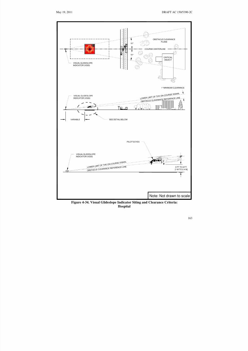
8/3/2019 draft_150_5390_2C
http://slidepdf.com/reader/full/draft15053902c 171/198
L O W E R L I M I T O
F T H E O N- C O U R
S E S I G NA L
OBS TACLE CLEARA
NCE REFERENCE
LINE
L O W E R L I M I T O
F T H E O N- C O U
R S E S I G NA L
OBS TACLE CLEAR
ANCE REFERENCE
LINE
May 19, 2011 DRAFT AC 150/5390-2C
10°
OBSTACLE CLEARANCE
PLANE
COURSE CENTERLINE
VISUAL GLIDESLOPE
INDICATOR (VGSI)
10°
CRITICAL
OBJECT
1°MINIMUM CLEARANCE
VISUAL GLIDESLOPE
INDICATOR (VGSI)
VARIABLE SEE DETAIL BELOW
PILOT'S EYES
VISUAL GLIDESLOPEINDICATOR (VGSI)
3 FT TO 8 FT
[1 M TO 2.4 M]
Note: Not drawn to scale
Figure 4-34. Visual Glideslope Indicator Siting and Clearance Criteria:
Hospital
163

8/3/2019 draft_150_5390_2C
http://slidepdf.com/reader/full/draft15053902c 172/198
DRAFT AC 150/5390-2C May 19, 2011
Intentionally left blank
164

8/3/2019 draft_150_5390_2C
http://slidepdf.com/reader/full/draft15053902c 173/198
May 19, 2011 DRAFT AC 150/5390-2C
CHAPTER 5. HELICOPTER FACILITIES ON AIRPORTS 501. GENERAL. Helicopters are able to operate on most airports without unduly interfering withairplane traffic. Separate facilities and approach/departure procedures may be necessary when the volumeof airplane and/or helicopter traffic affects operations. At airports with interconnecting passenger traffic,
the terminal apron should provide gates for helicopter boarding. Persons who use a helicopter to go to anairport generally require convenient access to the airport terminal and the services provided to airplanepassengers. The airport layout plan (ALP) should identify the location of the exclusive-use helicopterfacilities, TLOFs, FATOs, safety areas, approach/departure paths, and helicopter taxi routes and taxiways.This chapter addresses design considerations for providing separate helicopter facilities on airports.Figure 5-1 on page 167 shows an example of a heliport located on an airport. Other potential heliportlocations are on the roofs of passenger terminals or parking garages serving passenger terminals. Unlessotherwise noted, the standards in Chapter 2 starting on page 15 apply to helicopter facilities serving GAoperations and the standards in Chapter 3 starting on page 67 apply to helicopter facilities servingtransport operations.
502. TOUCHDOWN AND LIFTOFF AREA (TLOF). The TLOF should be located and designed to
provide ready access to the airport terminal or to the helicopter user’s origin or destination.
503. FINAL APPROACH AND TAKEOFF AREA (FATO). The recommended distance betweenthe centerline of an approach to a runway and the centerline of an approach to a FATO for simultaneous,same direction, VFR operations is provided in Table 5-1.
Table 5-1. Recommended Distance Between FATO Center to Runway Centerline for VFR
Operations
Helicopter Size
Airplane Size Small Helicopter
6,000 lbs or less
Medium Helicopter
6,001 to 12,000 lbs
Large Helicopter
over 12,000 lbs
Small Airplane
12,500 lbs or less
300 feet
(91 m)
500 feet
(152 m)
700 feet
(213 m)
Large Airplane
12,000 lbs to 300,000 lbs
500 feet
(152 m)
500 feet
(152 m)
700 feet
(213 m)
Heavy Airplane
Over 300,000 lbs
700 feet
(213 m)
700 feet
(213 m)
700 feet
(213 m)
504. SAFETY AREA. Safety area dimensions and clearances described in Chapter 2 are applied tofacilities being developed on an airport for GA helicopter usage. safety area dimensions and clearances
given in Chapter 3 are applied to facilities being developed on an airport for transport helicopter usage.
505. VFR APPROACH/DEPARTURE PATHS. To the extent practical, helicopterapproach/departure paths should be independent of approaches to and departures from active runways.
506. HELIPORT PROTECTION ZONE (HPZ). Where it is practicable for the airport owner toacquire and plan the land uses within the HPZ, the HPZ must be established. Where this is notpracticable, the HPZ standards have recommendation status for that portion of the HPZ not controlled bythe airport owner.
165

8/3/2019 draft_150_5390_2C
http://slidepdf.com/reader/full/draft15053902c 174/198
DRAFT AC 150/5390-2C May 19, 2011
507. TAXIWAYS AND TAXI ROUTES. When exclusive helicopter taxiways or taxi routes aredeveloped at an airport, they should be located to minimize interaction with airplane operations.
508. HELICOPTER PARKING. Helicopter parking positions should be located as close to theintended destination or origination of the passengers as conditions and safety permit.
509. SECURITY. Unless screening was carried out at the helicopter passengers’ departure location,Transportation Security Administration regulations may require that a screening area and/or screening beprovided before passengers enter the airport's secured areas. Multiple helicopter parking positions and/orlocations may be needed in the terminal area to service helicopter passenger screening and/or cargointerconnecting needs. Information about passenger screening is available at Transportation SecurityAdministration web site http://www.tsa.gov/public /.
166

8/3/2019 draft_150_5390_2C
http://slidepdf.com/reader/full/draft15053902c 175/198
N
May 19, 2011 DRAFT AC 150/5390-2C
RUNWAY 6-24 (150 X 7700) PAVED
SEETABLE 5-1Table 5-1
APPROACH/ DEPARTURE
SURFACE
GA/CORPORATEAPRON
TLOF/ HELIPORTFATOOPERATIONS
AREAS
APPROACH/ DEPARTURE
SURFACE
Ea rh a rt R e g i o n a l Ai rp o rt Li n d b e r g h , So u t h D a k o t a
Ai rp o rt Lo c a t io n :
4 4°- 58 ' N , 1 0 3° -46 " W Ai rp o r t El e v a t i o n :
KEY PLAN 3 , 0 2 2 Fe e t Ab o v e S e a Le v e l
Figure 5-1. A Heliport Located on an Airport:
On Airport
167

8/3/2019 draft_150_5390_2C
http://slidepdf.com/reader/full/draft15053902c 176/198
DRAFT AC 150/5390-2C May 19, 2011
Intentionally left blank
168

8/3/2019 draft_150_5390_2C
http://slidepdf.com/reader/full/draft15053902c 177/198
May 19, 2011 DRAFT AC 150/5390-2C
CHAPTER 6. INSTRUMENT OPERATIONS 601. GENERAL. Instrument approach/departure/missed approach procedures permit helicopteroperations to continue during periods of low cloud ceilings and reduced visibility. Instrument approachprocedures are established in accordance with FAA 8260 series Orders published by FAA Flight
Procedures Standards Branch. When a heliport does not meet the criteria of this AC, or FAA 8260 SeriesOrders, the helicopter instrument approach procedure will be published as a SPECIAL procedure, withannotations that special aircrew qualifications, pilot training and aircraft equipment are required to fly thespecific procedure (s).
602. PLANNING. This chapter addresses issues that heliport owners should consider beforerequesting the development of instrument approach/departure/missed approach procedures. Therecommendations and standards in this AC are not intended to be sufficient to design an instrumentprocedure. Heliport owners desiring instrument procedures are urged to initiate early contact with theappropriate FAA Flight Procedures Office.
603. AIRSPACE. Those who design instrument approach/departure/missed approach procedures have
some flexibility in the design of such procedures. For this and other reasons, the airspace required tosupport helicopter instrument approach/departure operations is complex, and it does not lend itself tosimple descriptions, even using figures. Refer to the latest revision of FAA Order 8260 series for moredetailed information on criteria for developing helicopter instrument approach/departure/missed approachprocedures.
604. FINAL APPROACH REFERENCE AREA (FARA). For precision instrument proceduresonly, a certificated helicopter precision approach procedure terminates with the helicopter coming to ahover or touching down within a 150-foot-wide (45 m) by at least 150-foot long (45 m) FARA. TheFARA is located at the far end of a 300-foot-wide by 1,225-foot- long (91 m by 373 m) FATO requiredfor a precision instrument procedure. For the purposes of requirements for LBA and lighting, the FARAis substituted for the FATO. Figure 6–1 on page 170 illustrates the FARA/FATO relationship.
605. IMPROVED LIGHTING SYSTEM. Lower visibility minimums may be possible if the lightingsystems described below are installed (see Figure 6–2 on page 171 and Figure 6–3 on page 172).
a. FATO Perimeter Lighting Enhancement. An additional raised, green light meeting thestandards of FAA Airports Engineering Brief 87, Heliport Lighting
4 is inserted between each light in thefront and rear rows of the raised perimeter lights to enhance the definition of the FATO.
b. Heliport Instrument Lighting System. The HILS consists of 24 unidirectional PAR 56,200-watt white lights that extend the FATO perimeter lights. The system extends both the right and leftedge lights as “edge bars” and both the front and rear edge lights as “wing bars,” as shown in Figure 6–2on page 171.
(1) Edge Bars. Edge bar lights are spaced at 50-foot (15.2 m) intervals, measured from thefront and rear row of the FATO perimeter lights.
4 As of the date of this draft, EB-87 has not been completed. Guidance on heliport lighting will be published as soonas possible.
169

8/3/2019 draft_150_5390_2C
http://slidepdf.com/reader/full/draft15053902c 178/198
DRAFT AC 150/5390-2C May 19, 2011
(2) Wing Bars. Wing bar lights are spaced at 15-foot (4.57 m) intervals, measured from theline of FATO perimeter (side) lights.
(3) Optional TLOF Lights. An optional feature is a line of seven white flush lights meetingthe standards of EB 87 spaced at 5-foot (1.5 m) intervals installed in the TLOF pavement. These lights arealigned on the centerline of the approach course to provide close-in directional guidance and improve
TLOF surface definition. These lights are illustrated in Figure 6–2 on page 171.
c. Heliport Approach Lighting System (HALS). The HALS, depicted in Figure 6–3 on page172 is a distinctive approach lighting configuration designed to prevent it from being mistaken for anairport runway approach lighting system.
606. OBSTACLE EVALUATION SURFACES. The helicopter instrument approach proceduredesign depends upon the specific heliport location, its physical characteristics, the terrain, surroundingobstructions, etc., that are all taken into consideration by the instrument procedure developer.
PRECISION INSTRUMENT FATO
1.225 FT [373 M]
150 FT[46 M]
300 FT[91 M]
150 FT[46 M]
FARA
Note: The illustrated FARA-FATO relationship is appropriate for a heliport at an elevationup to 1,000 ft [305 M] above mean sea level.
Figure 6–1. FARA/FATO Relationship:
Precision
170

8/3/2019 draft_150_5390_2C
http://slidepdf.com/reader/full/draft15053902c 179/198
May 19, 2011 DRAFT AC 150/5390-2C
Wing Bars and Edge Bars:PAR 56, 200 watt clear light
Flush TLOF Centerline Light:L-850A, 200 watt lights
Flush FATO edge light:L-861 SE, 115 watt yellow light(Note: Raised FATO edge lightsare also an option. Rased FATOedge lights would be placed outside
Perimeter Enhancement Light:
L-861 SE, 115 watt yellow lights
Note: The depicted HILS installation is appropriate to a minimally sized heliport located at anelevation up to 1,000 ft [305 M] above mean sea level.
Legend:
LIGHTEDWIND CONE
WING BAR
4 EQL SP
OF 15' [4.6 M]
the FATO per paragraph 210d(3) and
3 EQL SP
OF 50 FT [15.2 M]
EDG
E
BAR
(Optional - 5 ft [1.5 M] spacing)
OMNI-DIRECTIONALLIGHTS
5 ADDITIONAL
310c(2).1)
OPTIONAL TLOF
LIGHTS
Figure 6–2. Heliport Instrument Lighting System (HILS): Nonprecision
171

8/3/2019 draft_150_5390_2C
http://slidepdf.com/reader/full/draft15053902c 180/198
DRAFT AC 150/5390-2C May 19, 2011
The depicted HALS is appropriate for
The depicted HILS has elevated FATO
Notes:
FARA
PRECISION
INSTRUMENTFATO
HELIPORT APPROACHLIGHT SYSTEM (HALS)
10 LIGHT BARS
@ 100 FT [30.5 M] SPACING
a heliport located at an elevation up to1,000 ft [305 m] above mean sea level.
1.
2.edge lights. Flush FATO edge lights arealso an option. Flush FATO edge lightswould be placed just inside the FATOper paragraph 210d(1) and 310c(1).
Note: Not drawn to scale
Figure 6–3. Heliport Approach Lighting System
172

8/3/2019 draft_150_5390_2C
http://slidepdf.com/reader/full/draft15053902c 181/198
May 19, 2011 DRAFT AC 150/5390-2C
CHAPTER 7. HELIPORT GRADIENTS AND PAVEMENT DESIGN 701. GENERAL. This chapter provides guidance on designing heliport pavements, including designloads, and addresses soil stabilization as a method of treating non paved operational surfaces. Operationalsurfaces such as the TLOF, FATO, safety areas, parking areas, taxi routes, and taxiways should present a
reasonably smooth, uniformly graded surface. The surfaces of a heliport should be designed to providepositive drainage.
702. TLOF GRADIENTS.
a. General Aviation Heliport. To ensure drainage, the TLOF should have a minimum gradientof 0.5 percent and a maximum gradient of 2.0 percent.
b. Transport Heliport. To ensure drainage, the TLOF should have a longitudinal gradientbetween 0.5 and 1.0 percent and a transverse gradient between 0.5 and 1.5 percent.
c. Hospital Heliport. To ensure drainage, the TLOF should have a gradient between 0.5 and
1.0 percent and a maximum gradient of 2.0 percent.
703. FATO GRADIENTS.
a. Load Bearing FATO. The recommended gradients for a load bearing FATO range from aminimum of 0.5 percent to a maximum of 5.0 percent. FATO grades in any areas where a helicopter isexpected to land should not exceed 2.0 percent. To ensure TLOF drainage, gradients of rapid runoff shoulders should range between 3.0 and 5.0 percent. These recommendations are illustrated in Figure 7-1below for a concrete TLOF and stabilized turf FATO.
b. Non-Load Bearing FATO. When the FATO is non-load bearing and/or not intended for useby the helicopter, there are no specific requirements for the gradient of the surface. In this case the
gradient should be 5 percent or more to ensure adequate drainage away from the area of the TLOF.However, non-load bearing surfaces must be stabilized (see paragraph 708.b below).
704. SAFETY AREA GRADIENTS. The surface of the safety area should not be steeper than adownward slope of 2:1 (2 units horizontal in 1 unit vertical). In addition, the surface of the safety areashould not be higher than the FATO edge.
705. PARKING AREA GRADIENTS. Parking area grades should not exceed 2.0 percent in any areawhere a helicopter is expected to park.
706. TAXIWAY AND TAXI ROUTE GRADIENTS. Taxiway longitudinal gradients should notexceed 2.0 percent. Transverse gradients should not be less than 0.5 percent nor greater than 2.0 percent.
173

8/3/2019 draft_150_5390_2C
http://slidepdf.com/reader/full/draft15053902c 182/198
DRAFT AC 150/5390-2C May 19, 2011
SAFETYTLOF SHOULDER FATO AREA
Notes:
1. Slope direction based on site topography.
2. For dimensions of the TLOF, shoulder, FATO and Safety Area, see appropriate chapter.
3. FATO non-load bearing surfaces should be stabilized.
Figure 7-1. Heliport Grades and Rapid Runoff Shoulder:
Gradients and Pavement
707. DESIGN LOADS. The TLOF and any load-bearing surfaces should be designed and constructedto support the weight of the design helicopter and any ground support vehicles. Loads are applied throughthe contact area of the tires for wheel-equipped helicopters or the contact area of the skid for skidequipped helicopters. Helicopter weights, landing gear configurations, and dimensional data are listed inAppendix B.
a. Static Loads. For design purposes, the design static load is equal to the helicopter'smaximum takeoff weight applied through the total contact area of the wheels or skids. Contact themanufacturers to obtain the contact area for the specific helicopters of interest.
b. Dynamic Loads. A dynamic load of one-fifth of a second or less duration may occur during ahard landing. For design purposes, dynamic loads should be assumed at 150 percent of the takeoff weightof the design helicopter. When specific loading data is not available, assume 75 percent of the weight of the design helicopter to be applied equally through the contact area of the rear two rear wheels (or the pairrear wheels of a dual-wheel configuration) of a wheel-equipped helicopter. For a skid equipped helicopterassume 75 percent of the weight of the design helicopter to be applied equally through the aft contactareas of the two skids of a skid-equipped helicopter. (See Figure 7-2 below.) The manufacturer should becontacted to obtain the aft contact area for a specific helicopter of interest.
174

8/3/2019 draft_150_5390_2C
http://slidepdf.com/reader/full/draft15053902c 183/198
May 19, 2011 DRAFT AC 150/5390-2C
c. Rotor Loads. Rotor downwash loads are approximately equal to the weight of the helicopterdistributed uniformly over the disk area of the rotor. Tests have established that rotor downwash loads aregenerally less than the loads specified in building codes for snow, rain, or wind loads typically used instructural design calculations.
708. PAVEMENT DESIGN AND SOIL STABILIZATION. Pavements distribute the helicopters’
weight over a larger area of the subsurface as well as provide a water-impervious, skid-resistant wearingsurface. Paving TLOFs, FATOs, taxiways, and parking aprons is encouraged to improve their loadcarrying ability, minimize the erosive effects of rotor wash, and facilitate surface runoff. Stabilizingunpaved portions of the FATO and taxi routes subjected to rotor wash is recommended. In someinstances, loads imposed by ground support vehicles may exceed those of the largest helicopter expectedto use the facility. Guidance on pavement design and on stabilizing soils is contained in AC 150/5320-6, Airport Pavement Design and Evaluation, and AC 150/5370-10, Standards for Specifying Construction of
Airports. The ACs are available at the Airports web site http://faa.gov/arp.
a. Pavements. In most instances, a 6-inch thick (15 cm) portland cement concrete (PCC)pavement is capable of supporting operations by helicopters weighing up to 20,000 pounds (9,070 kg).Thicker pavements are required for heavier helicopters or where the quality of the subsurface soil is
questionable. PCC pavement is recommended for all heliport surfaces used by helicopters.
b. Stabilizing Soils. Different methods of soil stabilization may be used to meet different siterequirements. Helicopter weight, ground support vehicle weight, operational frequency, soil analysis, andclimatic conditions should be considered in selecting the method(s) and extent of surface stabilization.
(1) Turf. A well-drained and well-established turf that presents a smooth, dense surface isgenerally considered to be the most cost-effective surface stabilization available. In some combinations of climates and weather conditions, turf surfaces are capable of supporting the weight of many of the smallerhelicopters for low frequency use by private and corporate operators during much of the year. Turf surfaces also provide reasonable protection against wind, rotor wash, or water erosion. Climatic and soilconditions dictate the appropriate grass species to use at the site.
(2) Aggregate Turf. Heliports located on soils that have poor load-carrying capabilitieswhen wet may be able to overcome this deficiency by mixing selected granular materials into the upper12 inches (30 cm) of the soil. Suitable granular materials for this purpose are crushed stone, pit-rungravel, coarse sand, or oyster shells. The ratio of aggregate to soil should be sufficient to improve thestability of the soil yet retain the soil’s ability to support grass. For additional guidance, see Item 217 of AC 150/5370-10, Standards for Specifying Construction of Airports.
c. Formed Masonry Shapes. Precast masonry shapes vary in size and shape-from a brick paverto an open block. Pavers can be laid on a prepared bed to present a solid surface. Precast blocks can beembedded in the soil with grass growing in the natural openings. Architectural catalogs identify differentmasonry shapes that are commercially available for this purpose.
d. Pierced Metal Panels. Perforated metal panels that allow grass to grow through the openingscan be laid on the ground to provide a hard surface for helicopter operations. Engineering catalogsidentify commercially available panels.
175

8/3/2019 draft_150_5390_2C
http://slidepdf.com/reader/full/draft15053902c 184/198
DRAFT AC 150/5390-2C May 19, 2011
DYNAMIC LOAD = 1.5 X GW
0.75 X GW 0.75 X GWTYPICAL SINGLE WHEEL CONFIGURATION
DYNAMIC LOAD = 1.5 X GW
0.75 X GW 0.75 X GWTYPICAL DUAL WHEEL CONFIGURATION
CONTACT AREA
D
GW = GROSS WEIGHT D = SKID TUBE DIAMETER
DCL = CUFF LENGTH C = CONTACT AREA = 2 x 12
1CL
TYPICAL SKID CONFIGURATION
Figure 7-2. Helicopter Landing Gear Loading: Gradients and Pavement
176

8/3/2019 draft_150_5390_2C
http://slidepdf.com/reader/full/draft15053902c 185/198
May 19, 2011 DRAFT AC 150/5390-2CAppendix A
APPENDIX A. EMERGENCY HELICOPTER LANDING FACILITIES (EHLF)
A-1. GENERAL. Preplanning emergency landing areas will result in safer and more effective air-support operations. These facilities comprise rooftop emergency facilities and medical emergency sites.The following guidance is suggested as a guide for developing emergency helicopter landing facilities
(EHLF).
A-2. NOTIFICATION AND COORDINATION. Since an EHLF is not intended to function as aheliport, notification to the FAA under 14 CFR part 157 is not required. Proponents of EHLFs shouldadvise the local Air Traffic Control facility of the EHLF.
A-3. ROOFTOP EMERGENCY FACILITIES. To facilitate fire fighting or emergency evacuationoperations, local building codes may require structures over a specified height to provide a clear area onthe roof capable of accommodating a helicopter.
a. Building Code Requirements. Rooftop facilities must comply with State and local buildingcode requirements. The landing surface should be developed to the local fire department requirements
based on the size and weight of the helicopter(s) expected to engage in fire or rescue operations (seeFigure A-1). Additional information is available in NFPA 418, Standards for Heliports.
b. TLOF.
(1) Size. The TLOF should be square, rectangular or circular in configuration and centeredwithin the EHLF. It should be at least 40 feet in length and width or diameter.
(2) Weight Capacity. The TLOF should be designed to accept a 13,500-pound gross weight(GW) helicopter plus an impact load of 1.5 times GW.
(3) Access. The TLOF should provide two pedestrian access points at least 90 degrees apart
with a minimum of 60 feet TLOF perimeter separation.
(4) Drainage. Surface drainage should flow away from pedestrian access points, with amaximum slope of 1.5 percent.
c. FATO. The FATO should be at the same level as the TLOF.
(1) Size. The FATO should extend a distance of at least 45 feet in all directions from thecenter of the EHLF. For safe operation, clearance is required between the helicopter’s main and tail rotorblades and any object that could be struck by these blades. This clearance should be one third of the rotordiameter (RD) of the largest helicopter expected but not less than 20 feet (6.1 m).
(2) Obstructions. The FATO may be an imaginary surface outside the TLOF and extend
beyond the structures edge The FATO should be unobstructed and without penetration of obstacles suchas parapets, window washing equipment, penthouses, handrails, antennas, vents, etc.
d. Safety Area. A clear, unobstructed area, a minimum of 12 feet wide, should be provided onall sides, outside and adjacent to the FATO.
e. Safety Net. If the platform is elevated 4 feet or more above its surroundings, title 29 CFRpart 1910.23, Guarding floor and wall openings and holes, requires the provision of fall protection.
177

8/3/2019 draft_150_5390_2C
http://slidepdf.com/reader/full/draft15053902c 186/198
DRAFT AC 150/5390-2C May 19, 2011Appendix A
However, permanent railings or fences must not be used since they would be safety hazards duringhelicopter operations. An alternate method of installing a safety net, meeting state and local regulationsbut not less than 5 feet (1.5 m) wide, is suggested. The safety net should have a load carrying capability of 25 lbs/ft2 (122 kg/m2). The net must not project above the level of the TLOF. Both the inside and outsideedges of the safety net should be fastened to a solid structure. Nets should be constructed of material thatis resistant to environmental effects.
f. Markings.
(1) TLOF Perimeter. A solid 12-inch wide (30 cm) wide red or orange line should definethe limits of the touchdown pad as illustrated in Figure A-1.
(2) Touchdown/Positioning Circle (TDPC) Marking. A 12-inch wide red or orangecircular marking, 30 feet in diameter, should be centered within the TLOF. The background within thecircle should be a contrasting color.
(3) Weight Capacity. The TLOF should be marked with the maximum takeoff weight of thedesign helicopter, in units of thousands of pounds (e.g. a number “9,” indicating 9,000 pounds GW), with
each numeral ten feet in length, should be centered within the TLOF.
(4) Markings for pedestrians. Rooftop access paths, EHLF access paths, and assemblyzone(s) should be clearly marked with surface paint and instructional signage.
g. Access.
(1) Stairs. A minimum of two rooftop access stairs, with no less than 150 degrees separation,should connect to the top floor of the structure, with at least one providing access to the structure’semergency staircase.
(2) Doors. Penthouse and stairwell rooftop access doors should remain unlocked at all times
to provide access to the EHLF. Doors may be equipped with “panic bar” hardware and/or alarmed.
h. Wind Cone. A wind cone assembly with an orange wind cone should be located within theline of sight from the EHLF and outside the approach/departure path(s).
i. Lighting. Ambient rooftop lighting should be shielded to avoid affecting the pilot’s vision.
A-4. MEDICAL EMERGENCY SITES. Medical emergency sites are clear and level areas near thescene of an accident or incident that have been selected or designated by the local emergency responseteam as the place where the helicopter air ambulance is directed to land in order to transport an injuredperson to a hospital. Such sites should be provided in various locations within a jurisdiction to supportfast response to medical emergencies and accidents. Predesignating medical emergency sites provides theopportunity to inspect potential sites in advance and to select sites that have adequate clearapproach/departure airspace and adequate clear ground space.
178

8/3/2019 draft_150_5390_2C
http://slidepdf.com/reader/full/draft15053902c 187/198
May 19, 2011
OPTIONAL WIND CONE
CAUTIONHELICOPTER LANDING
AREASAFETY
AVOIDREAR
HELICOPTERAREAOF
STAYCLEAROF THE
AREAOF ROTORAVOIDREAR TAIL
HELICOPTER
APPROACHANDLEAVE
INA CROUCHEDMANNERHELICOPTERF ROM THE SIDE
WHENROTORS ARE TURNING
INSTRUCTIONS
AUTHORIZEDPERSONNEL
ONLY
DRAFT AC 150/5390-2CAppendix A
ROOF SHOULD BE FREE
OF LOOSE GRAVEL
12 IN [30cm] WIDE RED/ORANGECIRCLE AND PERIMETER MARKING
Note: 9,000 pound weight limitation indicated in center of circle.
POST AT PERSONNEL ENTRANCE
Figure A-1. Rooftop Emergency Landing Facility
179

8/3/2019 draft_150_5390_2C
http://slidepdf.com/reader/full/draft15053902c 188/198
DRAFT AC 150/5390-2C May 19, 2011Appendix A
Intentionally left blank
180

8/3/2019 draft_150_5390_2C
http://slidepdf.com/reader/full/draft15053902c 189/198
May 19, 2011 DRAFT AC 150/5390-2CAppendix B
APPENDIX B. HELICOPTER DATA
B-1. INTRODUCTION. This appendix contains selected helicopter data needed by a heliport designer.These data represent the most critical weight, dimensional, or other data entry for that helicopter model,recognizing that specific versions of the model may weigh less, be smaller in some feature, carry fewer
passengers, etc.
B-2. VERIFICATION. The published information has been verified by the various helicoptermanufacturers but should be confirmed by contacting the manufacturer(s) of the specific helicopter(s) of interest.
Table B-1. Legend for Table B-2
A Manufacturer name and helicopter model
B Maximum takeoff weight in pounds.
D Overall length in feet. (Rotors at their maximum extension.)
H Overall height in feet. (Usually at tail rotor.)
RD Rotor diameter in feet.E Number of blades.
F Rotor plane clearance in feet.
TR Distance from rotor hub to tip of tail rotor in feet.
I Tail rotor diameter (in feet).
J Number of tail rotor blades.K Tail rotor ground clearance in feet.
L Type of undercarriage.
UCL Undercarriage length in feet.
UCW Undercarriage width in feet. (The distance between the outside edges of the tires or theskids.)
M Number and type of engines
N Number of crew and passengers.
181

8/3/2019 draft_150_5390_2C
http://slidepdf.com/reader/full/draft15053902c 190/198
DRAFT AC 150/5390-2C May 19, 2011Appendix B
Table B-2. Helicopter Data
Manufacturer/ Model
M a x T a k e o f f W e i g h t
O v e r a l l L
e n g t h ( f t )
O v e r a l l H
e i g h t ( f t ) Main Rotor Tail Rotor Undercarriage
N u m b e r o f E n g i n e s /
T y
p e
C r e w N u m
b e r / P a x
N u m
b e r
D i a m e t e r ( f t )
N u m b e r o f B l a d e s
G r o u n d C l e a r
a n c e
( f t )
T a i l R t r A r c R
a d i u s
( f t )
D i a m e t e r ( f t )
N u m b e r o f B l a d e s
G r o u n d C l e a r
a n c e
( f t )
T y p e
L e n g t h ( f t )
W i d t h ( f t
)
A B D H RD E F TR I J K L UCL UCW M N
Agusta/ Westland
A-109A 5,732 42.8 11.2 36.1 4 10 25 6.7 2 2.3 wheel 11.6 7.5 2-T1-2&6-7
A-119 Koala 5,997 42.7 12.4 36.6 4 8.3 25.5 6.4 2 4.2 skid 13.4 5.5 1-T 1&6-7
AW-109E Power 6,283 42.8 11.5 36.1 4 8 6.4 2 3 wheel 11.5 7.1 2-T 1&7
AW-109S Grand 7,000 42.5 11.2 35.5 4 8 6.4 2 3.3 wheel 12.3 7.1 2-T1-2&6-7
AW-119 Ke 6,283 42.4 11.8 35.5 4 9.3 6.4 2 3.8 skid 11.1 7 1-T 1&6-7
AW-139 14,991 54.7 16.4 42.6 5 12.9 8.9 4 7.5 wheel 14.2 10 2-T1-2&
15
AW-101 34,392 74.8 21.7 61 5 15.4 45 13.1 8.4 wheel 23 14.8 3-T 3&30
Westland WG30 12,800 52.2 15.5 43.7 4 12.5 31 8 4 7.5 wheel 17.9 10.1 2+T 2&19
Bell Helicopter
47G 2,950 43.6 9.3 37.1 2 5 25 6.1 2 3.5 skid 9.9 7.5 1-P 1&2-3
205B, UH-1H, HueyII, 210
206B-1,2,3
10,500
3,350
57.8
39.2
14.5
10.8
48
33.4
2
2
7.3
6
33.1
22.5
8.5
5.2
2
2
5.9
2.1
skid
skid
12.1
8.1
8.8
6.7
1-T
1-T
1&14
1&4
206L-1,3,4 4,450 42.4 10.9 37 2 6.4 24 5.4 2 3.5 skid 9.9 7.7 1-T 1&6
212 11,200 57.3 14.9 48.2 2 7.5 22.2 8.5 2 6.1 skid 12.1 8.8 2-T 1&14
214ST 17,500 62.2 15.9 52 2 6.5 37 9.7 2 3.5wheel/
skid12.1 8.6 2-T
2&16-17
222B, UT 8,250 50.3 12.2 42 2 9.2 29.2 6.9 2 2.7wheel/
skid12.2 7.8 2-T 1&9
230 8,400 50.3 11.7 42 2 9.2 29.2 6.9 2 2.7 wheel/ skid 12.2 7.8 2-T 1&9
407 5,250 41.4 10.2 35 4 7.8 24.3 5.4 2 3.2 skid 9.9 8.1 1-T 1&6
412EP, SP, HP 11,900 56.2 14.9 46 4 11.5 34 8.6 2 4.8 skid 12.1 9.5 2-T 1&14
427VFR 6,550 42.6 10.5 37 4 6.4 24.1 5.7 2 3.3 skid 10 8.3 2-T 1&7
429 7,000 43 13.3 36 4 8.5 5.4 2 3.5 skid 9.9 8.8 2-T 1&7
430 9,300 50.3 13.3 42 4 8.2 29.2 6.9 2 3.7wheel/
skid12.4 9.2 2-T 1&9
182
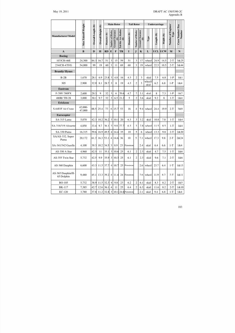
8/3/2019 draft_150_5390_2C
http://slidepdf.com/reader/full/draft15053902c 191/198
May 19, 2011 DRAFT AC 150/5390-2CAppendix B
Manufacturer/ Model
M a x
T a k e o f f W e i g h t
O v
e r a l l L e n g t h ( f t )
O v
e r a l l H e i g h t ( f t ) Main Rotor Tail Rotor Undercarriage
N u m b e r o f E n g i n e s /
T y p e
C r e w N u m b e r / P a x
N u m b e r
D i a m e t e r ( f t )
N u m b
e r o f B l a d e s
G r o u n
d C l e a r a n c e
( f t )
T a i l R t r A r c R a d i u s
( f t )
D i a m e t e r ( f t )
N u m b
e r o f B l a d e s
G r o u n
d C l e a r a n c e
( f t )
T y p e
L e n g t h ( f t )
W i d t h ( f t )
A B D H RD E F TR I J K L UCL UCW M N
Boeing
107/CH-46E 24,300 84.3 16.7 51 3 15 59 51 3 17 wheel 24.9 14.5 2-T 3&25
234/CH-47F/G 54,000 99 19 60 3 11 69 60 3 19 wheel 22.5 10.5 2-T 3&44
Brantly/ Hynes
B-2B 1,670 28.1 6.9 23.8 3 4.8 16 4.3 2 3 skid 7.5 6.8 1-P 1&1
305 2,900 32.9 8.1 28.7 3 8 19 4.3 2 3
wheel/
skid 6.2 6.8 1-P 1&4
Enstrom
F-28F/ 280FX 2,600 29.3 9 32 3 6 20.6 4.7 2 3.1 skid 8 7.3 1-P 1&2
480B/ TH-28 3,000 30.1 9.7 32 3 6.5 21.2 5 2 3.6 skid 9.2 8 1-T 1&4
Erickson
S-64E/F Air Crane42,00047,000
88.5 25.4 72 6 15.7 53 16 4 9.4 wheel 24.4 19.9 2-T 3&0
Eurocopter
SA-315 Lama 5,070 42.3 10.2 36.2 3 10.1 20 6.3 3 3.2 skid 10.8 7.8 1-T 1&4
SA-316/319 Alouette 4,850 33.4 9.7 36.1 3 9.8 27.7 6.3 3 2.8 wheel 11.5 8.5 1-T 1&4
SA-330 Puma 16,315 59.6 16.9 49.5 4 14.4 35 10 5 6 wheel 13.3 9.8 2-T 2&20
SA/AS-332, SuperPuma
SA-341/342 Gazelle
20,172
4,100
61.3
39.3
16.3
10.2
53.1
34.5
4
3
14.6
8.9
36
23
10
Fenstron
5 7.1
2.4
wheel
skid
17.3
6.4
9.8
6.6
2-T
1-T
2&24
1&4
AS-350 A Star 4,960 42.5 11 35.1 3 10.6 25 6.1 2 2.3 skid 4.7 7.5 1-T 1&6
AS-355 Twin Star 5,732 42.5 9.9 35.9 3 10.3 25 6.1 2 2.3 skid 9.6 7.1 2-T 1&6
AS-360 Dauphin 6,600 43.3 11.5 37.7 4 10.7 25 Fenstron 2.6 wheel 23.7 6.4 1-T 1&13
AS-365 Dauphin/H65 Dolphin
9,480 45.1 13.3 39.2 4 11.4 24 Fenstron 2.6 wheel 11.9 6.2 2-T 1&11
BO-105 5,732 38.9 11.5 32.3 4 9.8 23 6.2 2 6.1 skid 8.3 8.2 2-T 1&5
BK-117 7,385 42.7 12.6 36.1 4 11 25 6.4 2 6.3 skid 11.6 8.2 2-T 1&10
EC-120 3,780 37.8 11.2 32.8 3 10.1 24.6 Fenstron 2.1 skid 9.4 6.8 1-T 1&4
183

8/3/2019 draft_150_5390_2C
http://slidepdf.com/reader/full/draft15053902c 192/198
DRAFT AC 150/5390-2C May 19, 2011Appendix B
Main Rotor Tail Rotor Undercarriage
Manufacturer/ Model
M a x
T a k e o f f W e i g h t
O v
e r a l l L e n g t h ( f t )
O v
e r a l l H e i g h t ( f t )
D i a m e t e r ( f t )
N u m b
e r o f B l a d e s
G r o u n
d C l e a r a n c e
( f t )
T a i l R t r A r c R a d i u s
( f t )
D i a m e t e r ( f t )
N u m b
e r o f B l a d e s
G r o u n
d C l e a r a n c e
( f t )
T y p e
L e n g t h ( f t )
W i d t h ( f t )
N u m b e r o f E n g i n e s /
T y p e
C r e w N u m b e r / P a x
N u m b e r
A B D H RD E F TR I J K L UCL UCW M N
EC-130 5,291 41.5 11.8 35.1 3 11 23.7 Fenstron 5.3 skid 10.5 7.9 1-T 1&7
EC-135 6,250 40 11.5 33.5 4 11 22.8 Fenstron 5.6 skid 10.5 6.6 2-T 1&6
EC-145/ UH-72A 7,904 42.7 13 36.1 4 11.3 28 6.4 2 10.7 skid 9.5 7.9 2-T 1&8
EC-155 10,692 46.9 14.27 41.3 5 12 23 Fenstron 3.1 wheel 12.8 6.2 2-T 2&12
EC-225 24,332 64 16.3 53.1 5 15.1 38 10.3 4 3.5 wheel 17.2 9.8 2-T 2&24
Kaman
K-Max/ K1200 7,000 52 21 48.2 4 10.7 28 n a n/a wheel 15.3 11.3 1-T 1&0
SH-2G Seasprite 14,200 52.5 15.1 44 4 8.1 4 wheel 2-T 3&8
MD Helicopters
500E 3,000 30.8 8.4 26.4 5 8.2 4.6 2 2 skid 8.1 6.3 1-T 1&4
530F 3,100 32.1 8.1 27.4 5 8 19 4.8 2 1.3 skid 8.1 6.4 1-T 1&4
520N 3,350 32.1 9.7 27.4 5 9.2 17 NOTAR n/a skid 8.1 6.3 1-T 1&4
600N 4,100 36.9 9.8 27.5 6 9.2 NOTAR n/a skid 10.1 8.8 1-T 1&7
Explorer/ 902 6,500 38.8 12 33.8 5 12 23 NOTAR n/a skid 7.3 7.3 2-T1-2&6-7
Robinson
R-22 Beta 1,370 28.8 8.9 25.2 2 8.8 16 3.5 2 4.1 skid 4.2 6.3 1-P 1&1
R-44 Raven 2,500 38.3 10.8 33 2 10.5 22 4.8 2 3.8 skid 4.2 7.2 1-P 1&3
R-66 Turbine 2,700 38.3 11.4 33 2 10.5 5 2 3.6 skid 4.2 7.5 1-T 1&4
Fairchild-Hiller
Rogerson-Hiller
360/UH-12/OH-23 3,100 40.8 10.2 35.4 2 10.1 23 6 2 4 skid 8.3 7.5 1-P 1&3
FH/RH-1100 3,500 41.3 9.2 35.3 2 9.5 24 6 2 3 skid 7.9 7.2 1-T 1&4
Sikorsky/
Schweizer
HU-269A/A-1/B,TH55A
1,850 29 9 26 3 8.8 15 3.8 2 2.5 skid 8.3 6.5 1-P 1&1
300C 2,050 30.8 8.7 26.8 3 8.7 15.3 4.3 2 2.8 skid 8.3 6.5 1-P 1&2
184

8/3/2019 draft_150_5390_2C
http://slidepdf.com/reader/full/draft15053902c 193/198
May 19, 2011 DRAFT AC 150/5390-2CAppendix B
Manufacturer/ Model
M a x
T a k e o f f W e i g h t
O v
e r a l l L e n g t h ( f t )
O v
e r a l l H e i g h t ( f t ) Main Rotor Tail Rotor Undercarriage
N u m b e r o f E n g i n e s /
T y p e
C r e w N u m b e r / P a x
N u m b e r
D i a m e t e r ( f t )
N u m b
e r o f B l a d e s
G r o u n
d C l e a r a n c e
( f t )
T a i l R t r A r c R a d i u s
( f t )
D i a m e t e r ( f t )
N u m b
e r o f B l a d e s
G r o u n
d C l e a r a n c e
( f t )
T y p e
L e n g t h ( f t )
W i d t h ( f t )
A B D H RD E F TR I J K L UCL UCW M N
300CB/CBi 1,750 30.8 8.7 26.8 3 8.7 15.3 4.3 2 2.8 skid 8.3 6.5 1-P 1&1
330/330SP/ 333 2,550 31.2 11 27.5 3 9.2 15.3 4.3 2 3.2 skid 8.3 6.5 1-T 1&2-3
S-434 2,900 31.2 11 27.5 4 9.2 15.3 4.3 2 3.2 skid 8.3 6.5 1-T 1&2-3
S-55/H19 7,900 62.6 13.1 53 3 8.2 2 wheel 1-T 2&12
S-58/H34 14,600 65.8 15.9 56 4 11.4 38 9.5 4 6.4 wheel 28.3 14 2-T 2&16
S-61/H-3 22,000 72.8 19 62 5 12.3 40 10.3 5 8.6 wheel 23.5 14 2-T 3&28
S-76A/B/C/D 11,700 52.5 14.6 44 4 8.2 30.5 8 4 6.5 wheel 16.4 8 2-T 2&12S-92 26,500 68.5 17.9 56.3 4 9.8 39.9 11 4 6.9 wheel 20.3 10.4 2-T 2&19
S-70i/UH-60LBlackhawk
22,000 64.8 16.8 53.8 4 7.7 38 11 4 6.6 wheel 29 9.7 2-T 3&12
CH-53K 74,000 99.5 27.8 79 7 17 59.6 20 4 9.5 wheel 27.3 13 3-T 3&55
185

8/3/2019 draft_150_5390_2C
http://slidepdf.com/reader/full/draft15053902c 194/198
R D
DRAFT AC 150/5390-2C May 19, 2011Appendix B
D
T R
H
A
I
K
U C W
U C L
D
T R
I
R D
H
A
K
U C W
U C L
Figure B–1. Helicopter Dimensions
186

8/3/2019 draft_150_5390_2C
http://slidepdf.com/reader/full/draft15053902c 195/198
May 19, 2011 DRAFT AC 150/5390-2CAppendix C
APPENDIX C. DIMENSIONS FOR MARKING SIZE AND WEIGHT LIMITATIONS
Introduction. The form and proportion of numbers for marking TLOF and parking area size and weightlimitations are shown below.
All characters shall have the following characteristics (Unless otherwise specified):
Horizontal stroke of 6 in [15 cm]Vertical stroke of 5 in [13 cm]
18 IN [46 cm] wide36 IN [91cm] high
12 IN [30 cm]
16 IN
[41 cm]
5 IN[13 cm]
13 IN
[33 cm]
3 IN[8 cm]
12 IN [30 cm]
5 IN [13 cm]13 IN [33 cm]
12 IN [30 cm]
7 IN [18 cm]
5 IN[13 cm]
2 PL
14 IN[35 cm]
10 IN [25 cm]
4 IN [10 cm]
10 IN [25 cm] HORIZONTALSTROKE
VERTICALSTROKE
2 IN [5 cm] 5 IN[13 cm]
10 IN [25 cm]24 IN [60 cm]
23 IN[58 cm]
2 IN [5 cm] 5 IN [13 cm]
12 IN [30 cm] 24 IN [60 cm]
DO NOT SCALE DRAWING
Figure C–1. Form and Proportions of 3 foot (0.9 m) Numbers for Marking Size and Weight Limitations
187

8/3/2019 draft_150_5390_2C
http://slidepdf.com/reader/full/draft15053902c 196/198
DRAFT AC 150/5390-2C May 19, 2011Appendix C
Horizontal stroke of 10 in [25 cm]Vertical stroke of 8 in [20 cm]
30 in [76 cm] wide60 in [152 cm] high
20 IN [51 cm]
26 IN
[66 cm]
8 IN
[20 cm]
22 IN[56 cm]
4 IN
[10 cm]
20 IN [51 cm]
8 IN [20 cm]22 IN [56 cm]
20 IN [51 cm]
12 IN [30 cm]
8 IN[20 cm]
2 PL
24 IN[61 cm]
16 IN [41 cm]
6 IN [15 cm]
16 IN [41 cm] HORIZONTAL
STROKE
VERTICAL
STROKE
4 IN [10 cm] 8 IN
[20 cm]
16 IN [41 cm]
40 IN [102 cm]
38 IN
[91 cm]
4 IN [10 cm] 8 IN [20 cm]
20 IN [51 cm] 40 IN [102 cm]
DO NOT SCALE DRAWING
All characters shall have the following characteristics (Unless otherwise specified):
Figure C–2. Form and Proportions of 5 foot (1.5 m) Numbers for Marking Size and Weight Limitation
188
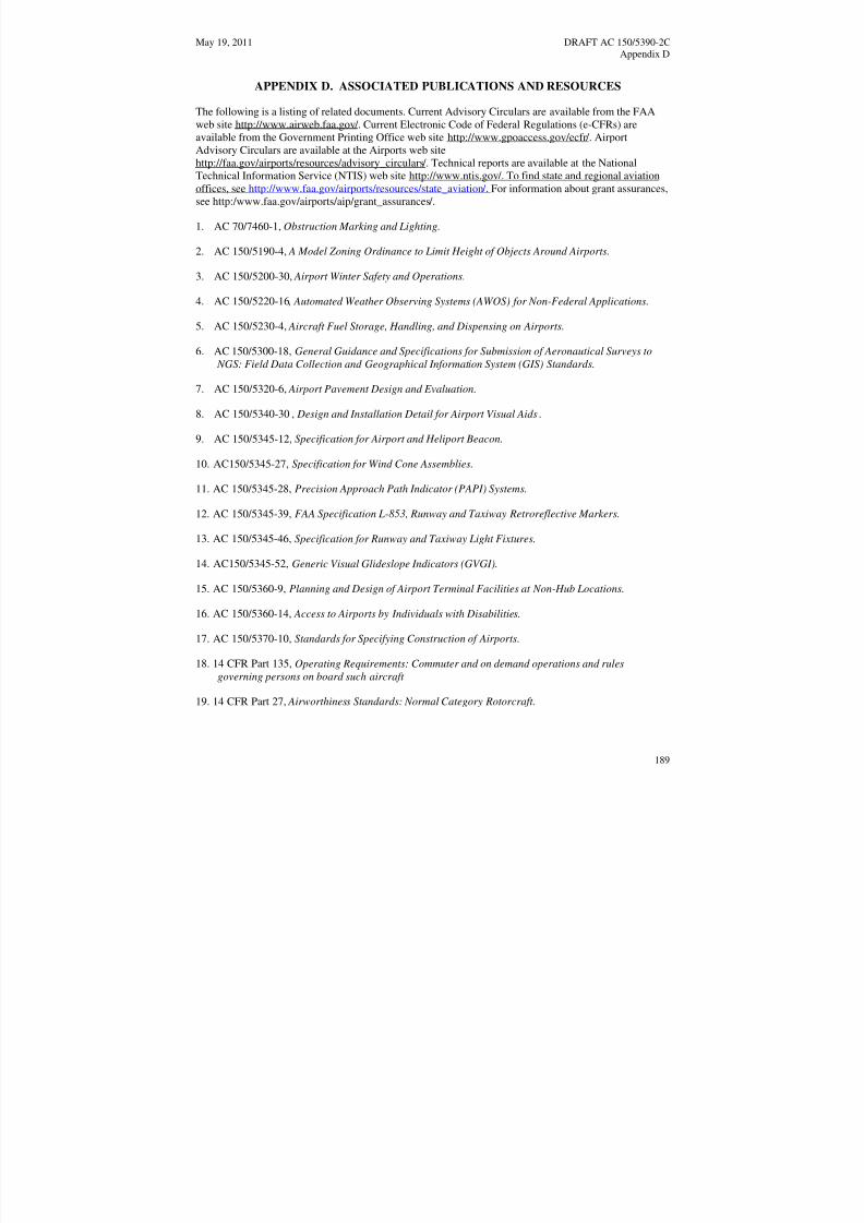
8/3/2019 draft_150_5390_2C
http://slidepdf.com/reader/full/draft15053902c 197/198
May 19, 2011 DRAFT AC 150/5390-2CAppendix D
APPENDIX D. ASSOCIATED PUBLICATIONS AND RESOURCES The following is a listing of related documents. Current Advisory Circulars are available from the FAAweb site http://www.airweb.faa.gov /. Current Electronic Code of Federal Regulations (e-CFRs) areavailable from the Government Printing Office web site http://www.gpoaccess.gov/ecfr /. Airport
Advisory Circulars are available at the Airports web sitehttp://faa.gov/airports/resources/advisory_circulars /. Technical reports are available at the NationalTechnical Information Service (NTIS) web site http://www.ntis.gov /. To find state and regional aviationoffices, see http://www.faa.gov/airports/resources/state_aviation / . For information about grant assurances,see http:/www.faa.gov/airports/aip/grant_assurances /.
1. AC 70/7460-1, Obstruction Marking and Lighting.
2. AC 150/5190-4, A Model Zoning Ordinance to Limit Height of Objects Around Airports.
3. AC 150/5200-30, Airport Winter Safety and Operations.
4. AC 150/5220-16 , Automated Weather Observing Systems (AWOS) for Non-Federal Applications.
5. AC 150/5230-4, Aircraft Fuel Storage, Handling, and Dispensing on Airports.
6. AC 150/5300-18, General Guidance and Specifications for Submission of Aeronautical Surveys to
NGS: Field Data Collection and Geographical Information System (GIS) Standards.
7. AC 150/5320-6, Airport Pavement Design and Evaluation.
8. AC 150/5340-30 , Design and Installation Detail for Airport Visual Aids.
9. AC 150/5345-12, Specification for Airport and Heliport Beacon.
10. AC150/5345-27, Specification for Wind Cone Assemblies.
11. AC 150/5345-28, Precision Approach Path Indicator (PAPI) Systems.
12. AC 150/5345-39, FAA Specification L-853, Runway and Taxiway Retroreflective Markers.
13. AC 150/5345-46, Specification for Runway and Taxiway Light Fixtures.
14. AC150/5345-52, Generic Visual Glideslope Indicators (GVGI).
15. AC 150/5360-9, Planning and Design of Airport Terminal Facilities at Non-Hub Locations.
16. AC 150/5360-14, Access to Airports by Individuals with Disabilities.
17. AC 150/5370-10, Standards for Specifying Construction of Airports.
18. 14 CFR Part 135, Operating Requirements: Commuter and on demand operations and rules
governing persons on board such aircraft
19. 14 CFR Part 27, Airworthiness Standards: Normal Category Rotorcraft.
189
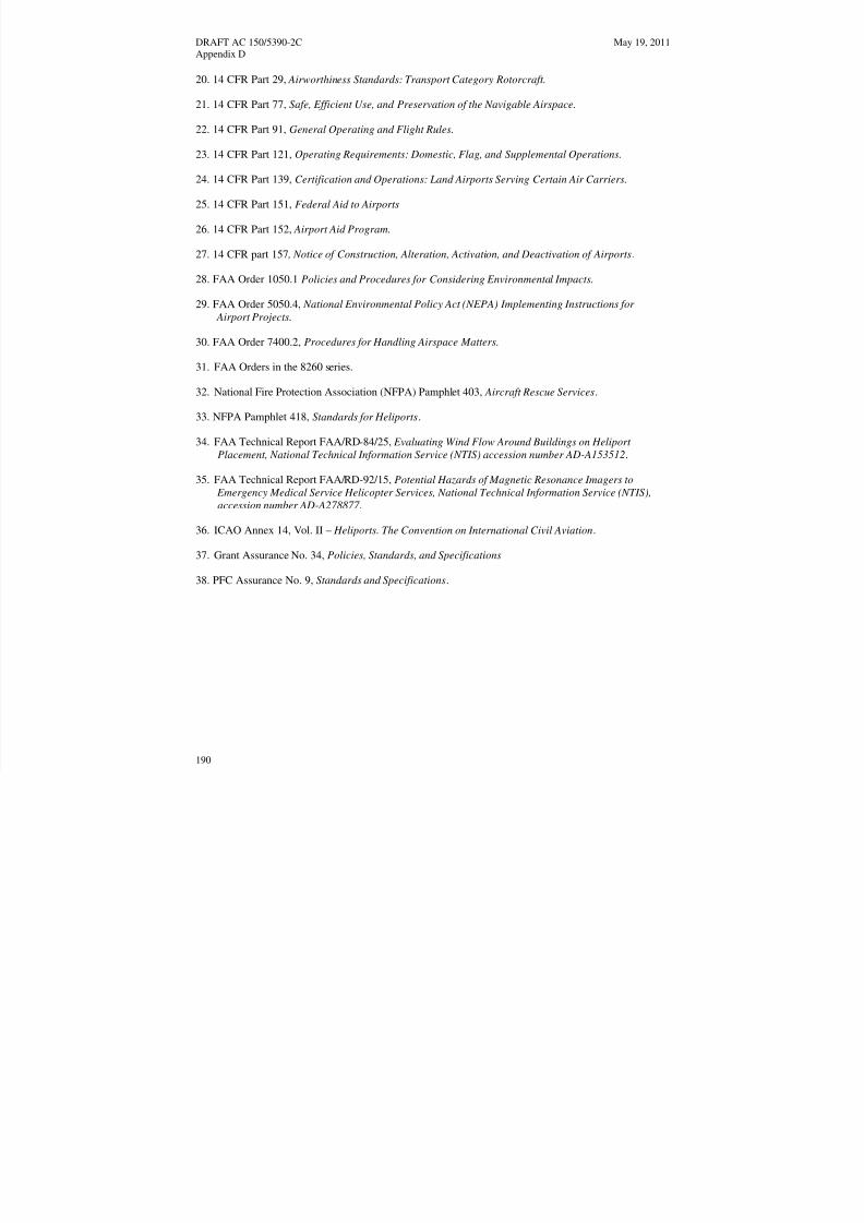
8/3/2019 draft_150_5390_2C
http://slidepdf.com/reader/full/draft15053902c 198/198


