Embed Size (px)
Citation preview
Draft
Analysis and Strengthening of Caisson Foundations for
Uplift Loads
Journal: Canadian Journal of Civil Engineering
Manuscript ID cjce-2015-0350.R1
Manuscript Type: Article
Date Submitted by the Author: 20-Jan-2016
Complete List of Authors: Guner, Serhan; University of Toledo, Civil Engineering Carriere, Jean; Morrison Hershfield Limited
Keyword: deep beams, micro piles, nonlinear analysis, retrofit, strut-and-tie method
https://mc06.manuscriptcentral.com/cjce-pubs
Canadian Journal of Civil Engineering
Draft
1
Analysis and strengthening of caisson foundations for uplift loads
Serhan Guner and Jean Carrière
Serhan Guner: Department of Civil Engineering, University of Toledo, Toledo, OH 43606, USA
Jean Carrière: Morrison Hershfield Limited, Toronto, ON L3T 7W4, Canada
Corresponding Author:
Serhan Guner, Ph.D., P.Eng.
Assistant Professor
Department of Civil Engineering
University of Toledo
2801 W Bancroft St. MS 307
Nitschke Hall 3021
Toledo, OH 43606-3390
P: 419-530-8133
W: www.utoledo.edu/engineering/faculty/serhan-guner
Page 1 of 38
https://mc06.manuscriptcentral.com/cjce-pubs
Canadian Journal of Civil Engineering
Draft
2
Abstract
Many existing self-supporting towers are built with constant-width caisson foundations. Due to
the increased demand to add more antennas to the towers, and more stringent strength
requirements in recently revised design standards, many existing caisson foundations require
significant strengthening for additional uplift resistance. Although a number of retrofit design
solutions are frequently used in practice, there is a lack of literature providing guidelines for the
proper analysis of retrofitted foundations. This study proposes a detailed analysis and design
methodology to significantly increase the uplift capacity of existing caissons through the use of
helical micro piles and reinforced concrete cap beams. Strut-and-tie models are developed and
nonlinear finite element analyses are undertaken to verify the behaviour of the proposed design.
The overall design methodology is presented in a case study involving an existing tower. The
proposed design has a general applicability and is suitable for applications where there is limited
space around the existing foundations.
Keywords: caisson foundations, deep beams, finite elements, micro piles, modeling, nonlinear
analysis, retrofit, strut-and-tie method, towers, uplift loads.
Page 2 of 38
https://mc06.manuscriptcentral.com/cjce-pubs
Canadian Journal of Civil Engineering
Draft
3
Introduction
New wireless technologies, such as LTE and 4G networks, have created an increased
demand for new telecommunication installation in the last decade. Due to high costs of installing
new towers and of purchasing land (especially in and around urban areas), it has become more
attractive for service providers to co-locate on existing towers – however, many of these towers
are at their design capacity. As a consequence, many existing towers require strengthening
through reinforcements to support the increased loads. The design of these reinforcements must
satisfy the latest version of the CSA S37 standard, which is generally more stringent in strength
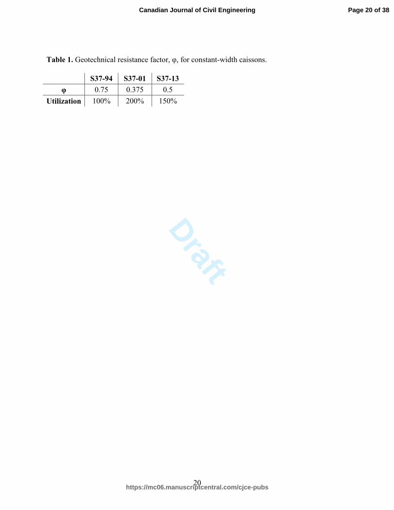
requirements than the previous editions of the standard. One critical change to this standard has
been a reduction in the resistance factor value for caisson foundations which are subjected to
uplift loads (see Table 1). A caisson foundation designed at capacity prior to 2001 would be
overloaded by a factor of 2.0 according to the 2001 edition of the standard, and by a factor of 1.5
according to the current 2013 edition of the standard. The latest standard has required significant
strengthening of many existing caisson foundations, especially those designed prior to 2001.
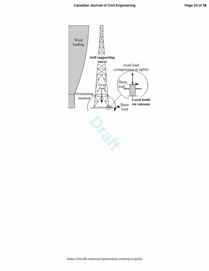
Caisson foundations are commonly used for self-supporting towers. These towers are
subjected to significant overturning moments, and small axial forces. The overturning moments
are resisted by the tensile and compressive resistance of the caisson foundations, as illustrated in
Fig. 1. Due to the changing nature of wind direction and pressure, caisson foundations are
exposed to cyclic load reversals. Compared to other foundation systems carrying a constant level
of axial compression, caisson foundations are subjected to a more complex state of stress.
Caissons typically resist the applied compression through skin friction and tip bearing, while the
tensile resistance is provided only by skin friction and self-weight of the caisson. Consequently,
Page 3 of 38
https://mc06.manuscriptcentral.com/cjce-pubs
Canadian Journal of Civil Engineering
Draft
4
strengthening of an existing caisson presents significant challenges to increase the uplift capacity
by a factor in excess of 1.5.
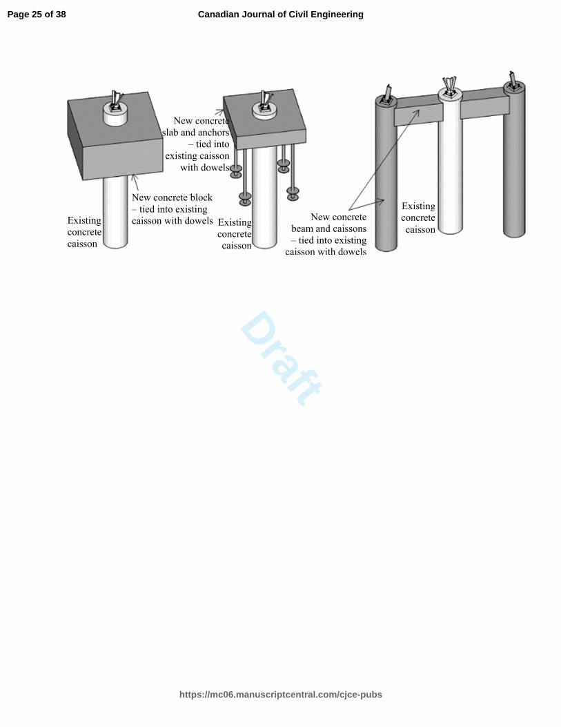
A number of schemes are commonly employed in industry to increase the uplift
capacities of existing caissons. Weight blocks, such as thick concrete slabs, are attached to
existing caissons for small overloads, using discontinuous dowel bars developed with epoxy-
based adhesives. For larger overloads, new anchors, such as micro piles or new caissons, are
attached to existing caissons or tower legs. Some examples of the commonly used retrofit
schemes are presented in Fig. 2. Although these retrofit schemes are frequently used in industry,
there are no known published guidelines for the proper analysis and design of the retrofitted
foundation systems. The connections between the existing caissons and the new retrofit elements
are particularly critical. If not analysed and designed properly, these retrofits could render an
entire design ineffective, which may result in structural failures due to overloads.
The objective of this study is to develop an analysis and design methodology for the
retrofit of existing caisson foundations for large uplift overloads. The main focus is to present the
detailed numerical analysis studies to provide a general framework for the proposed
methodology.
Literature Review
The literature investigating the behaviour, design, and strengthening of tower structures
remain very limited. Magued et al. (1989) presented a concise review of the evolution of the
CSA S37 standard from 1954 to 1986, with a particular focus on upgrading the strength levels of
existing towers. This study also presented a database that included failures of guyed towers taller
than 75 m located in Canada. Bruneau et al. (1989) proposed a set of guidelines for upgrading
Page 4 of 38
https://mc06.manuscriptcentral.com/cjce-pubs
Canadian Journal of Civil Engineering
Draft
5
existing towers, developed from a structural reliability analysis. They indicated that the failure
rate for guyed telecommunication towers was generally unacceptably high in Canada. Wahba et
al. (1994) analysed 41 guyed towers to justify the load factors to be used in the CSA S37-94
standard. Selby and Dryburgh (1996) conducted a number of comparative studies to determine
the conditions under which the patch load analysis of the CSA S37-94 standard was required for
guyed towers. Kumalasari et al. (2006) presented the results of an experimental study involving
seven solid steel round bracing members strengthened with rods and angles, and proposed a
simplified design procedure for the determination of compressive strength of such members.
Faridafshin and McClure (2008) examined three existing guyed tower masts and numerically
studied the effects of three earthquake records. Yet none of these studies addressed the lack of
literature investigating the structural strengthening of tower foundations. One published research
paper by Abdalla (2002) presented a case study involving self-supporting and guyed tower
foundations, and proposed repair and strengthening solutions. However, no numerical analysis
and verification studies were presented for the proposed methods.
Proposed Design Methodology with a Case Study
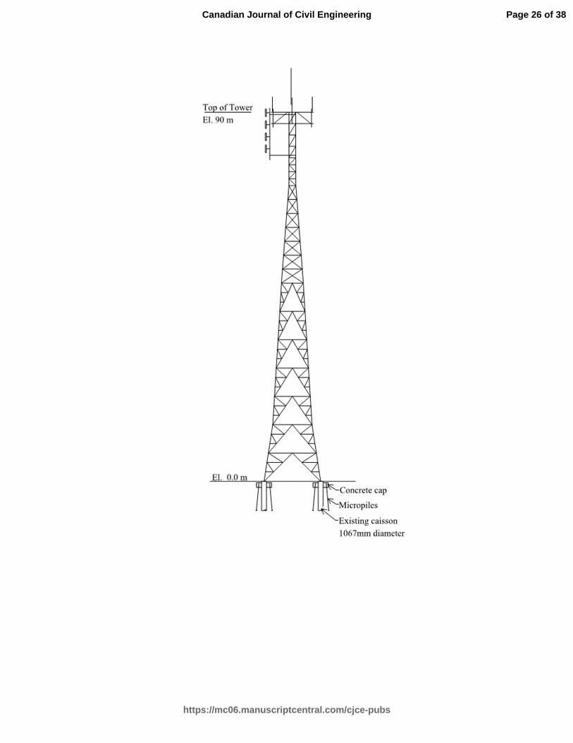
The tower examined has a height of 90 m with a face-width of 12.2 m at the base, as
shown in Fig. 3. The tower is located in a residential area of Toronto, Ontario. It was designed
and constructed in the early 1970s. Due to the high demand to add antennas on this tower, the
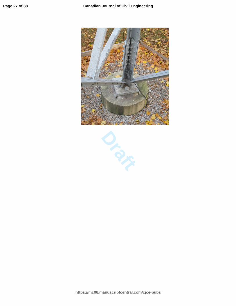
tower mast has been reinforced several times in recent years. The tower has three caisson
foundations (one is shown in Fig. 4), each with a diameter of 1067 mm, 30-#9 longitudinal
reinforcing bars, and #3 circular hoops spaced at 300 mm, as indicated on the original design
Page 5 of 38
https://mc06.manuscriptcentral.com/cjce-pubs
Canadian Journal of Civil Engineering
Draft
6
drawings. These drawings also specified a concrete compressive strength of 27.6 MPa, a
reinforcing steel yield strength of 414 MPa, and a concrete cover of 76 mm.
A detailed tower analysis was conducted for the increased loading. The analysis results
indicated the maximum factored uplift and compression reactions to be 1530 kN and 1740kN,
respectively, at each caisson. The factored uplift capacity was calculated to be 675 kN using the
geotechnical resistance factor of 0.375 in the CSA S37-01 standard. Considering the 136-kN
self-weight of the caisson, an overload factor of 2.1 was obtained. Allowing for a 6% reserve
capacity, an additional uplift capacity of 800 kN was required per caisson. To provide such a
significant additional resistance, new structural elements, such as new anchors or foundations,
should be considered. Due to the limited space available on the tower site, two helical micro
piles, each with 400 kN factored tensile capacity, was employed in the proposed design. The
design of the micro piles was conducted in a separate geotechnical study and is out of the scope
of this paper.
The main structural challenge in using micro piles is the difficulty of creating an effective
connection between the piles and the existing caissons while providing the required clearance
from the existing caissons. Among a few options, reinforced concrete cap beams emerge as one
practical alternative; however, a relatively large depth and width is required to provide the proper
space and stability to the micro pile heads. A depth of 1000 mm, which is approximately the
same as the existing caisson diameter, and a width of 800 mm was used in the proposed design.
A clear span of 700 mm from the face of the caisson to the pile head was required by the
geotechnical study. These dimensions result in a clear span to depth ratio of 0.7. Recall that the
CSA A23.3-14 standard classifies flexural members as deep members when the clear span to
Page 6 of 38
https://mc06.manuscriptcentral.com/cjce-pubs
Canadian Journal of Civil Engineering
Draft
7
depth ratios is less than 2.0, and subsequently requires the use of the strut-and-tie analysis
method and strict anchorage requirements for the tension reinforcement.
The following sections present the verification studies using the strut-and-tie method and
nonlinear finite element analyses.
Strut and Tie Modeling
Verification Uplift Forces
A strut-and-tie analysis was employed to verify the overall design and determine the
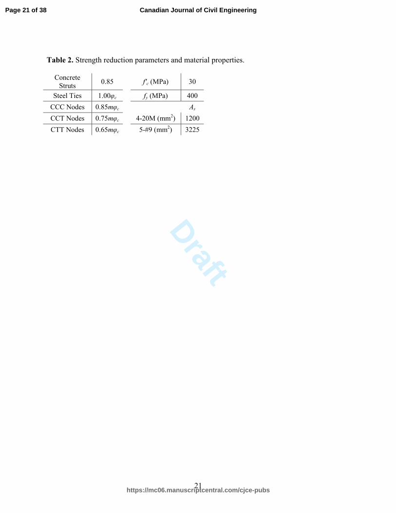
required quantities of reinforcing bars. The strength reduction parameters were taken according
to the CSA A23.3-14 standard, and the material properties were obtained from the original
design drawings, as listed in Table 2, where φc is the resistance factor for concrete (taken as
0.65), m is the confinement modification factor (taken as 1.0), C refers to compression, T refers
to tension, f’c is the specified compressive strength of concrete, fy is the specified yield strength
of the reinforcement, and As is the reinforcement area.
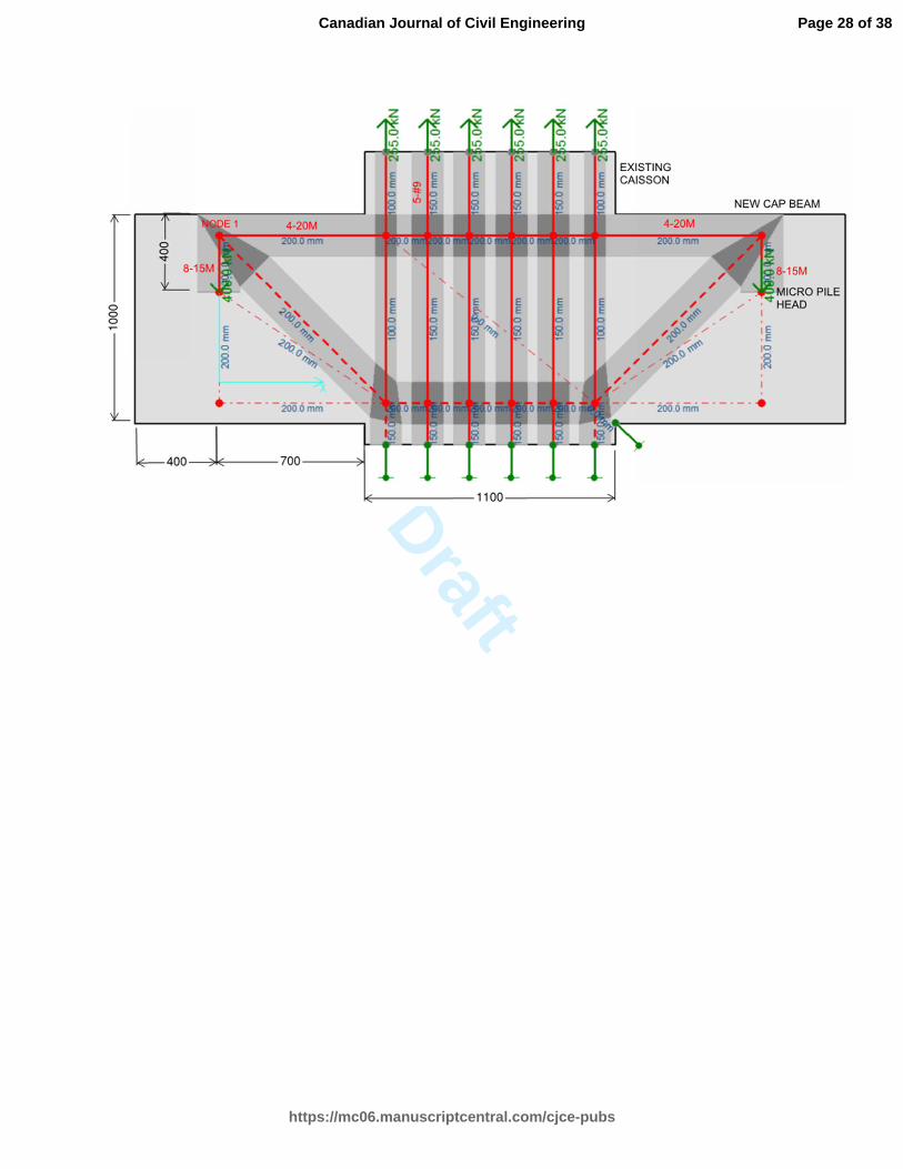
The vertical reinforcement of the existing caisson was modelled with six ties, each with
5-#9 bars. The main tension reinforcement was placed 100 mm from the top of the beam for a
clear cover of 75 mm and a stirrup bar size of 15M. The total factored leg load of 1530 kN was
applied equally over the six nodes at the top of the caisson. The micro pile reactions were
considered with two vertical point loads, each with a magnitude of 400 kN. The horizontal force
component of 1.5 kN due to the pile slope (specified to be less than 5°) was neglected in the
analysis. The geometry and the internal forces of the strut-and-tie model was determined with the
help of a computer program, CAST (Tjhin and Kuchma 2004). An iterative process was
employed to determine the geometry of the model and the minimum amount of reinforcement
Page 7 of 38
https://mc06.manuscriptcentral.com/cjce-pubs
Canadian Journal of Civil Engineering
Draft
8
required. Hand calculations were performed to determine the capacities of the struts, ties, and the
nodal zones according to the CSA A23.3-14 standard. The final model is presented in Fig. 5,
where the strut and tie widths are also shown.
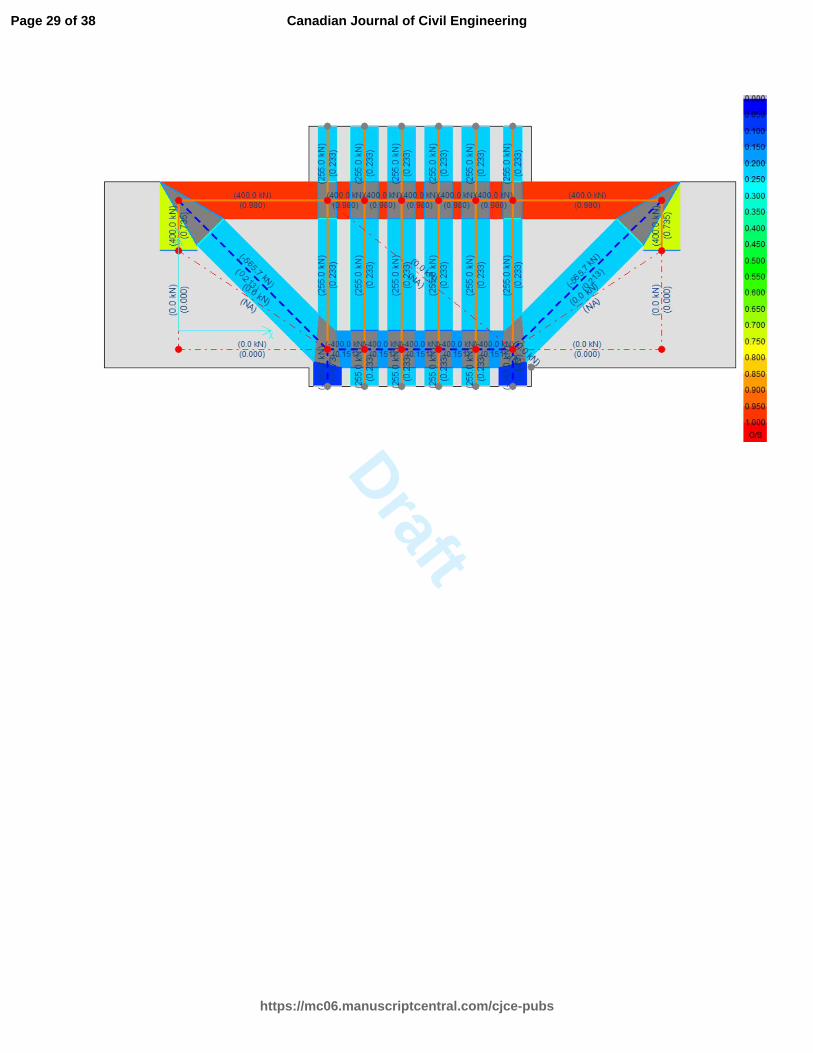
The analysis results in the form of unity factors (presented in Fig. 6) suggests that the
proposed design is adequate. The maximum stress ratio is 0.98 for the ties, 0.21 for the struts,
and 0.25 for the nodes. Despite the low concrete stresses, the width of the beam was kept at 800
mm due to stability reasons. The limiting component of the design was the main tension
reinforcement. In this study, 4-20M bars were used to obtain the minimum required design. It
should also be recalled that the design already considers some reserve capacity, the strain
hardening behaviour of the reinforcement was not considered, and the strut-and-tie analysis is a
conservative, lower-bound solution. Nonetheless, the use of 4-25M may be advisable to reduce
the maximum stress ratio to 0.59, given the negligible change in the construction costs.
In addition, 8-15M vertical reinforcement was used at the location of the micro pile to
transfer the pile tension to the node above (Node 1 in Fig. 5). It should be noted that this
reinforcement should be fully developed at Node 1, which can be achieved with a welded plate
or a closed stirrup. Two pairs of 15M stirrups (with four legs each) were used at each side of the
pile in this study. Also note that this tie reinforcement was not designed to be at capacity,
considering the construction variability and the beneficial effects of additional confinement at
this critical location.
Verification for Compression Forces
There is no need for the strengthening of the caisson for the compression loads for this tower.
The maximum factored compression reaction was calculated to be 1740 kN, while the existing
Page 8 of 38
https://mc06.manuscriptcentral.com/cjce-pubs
Canadian Journal of Civil Engineering
Draft
9
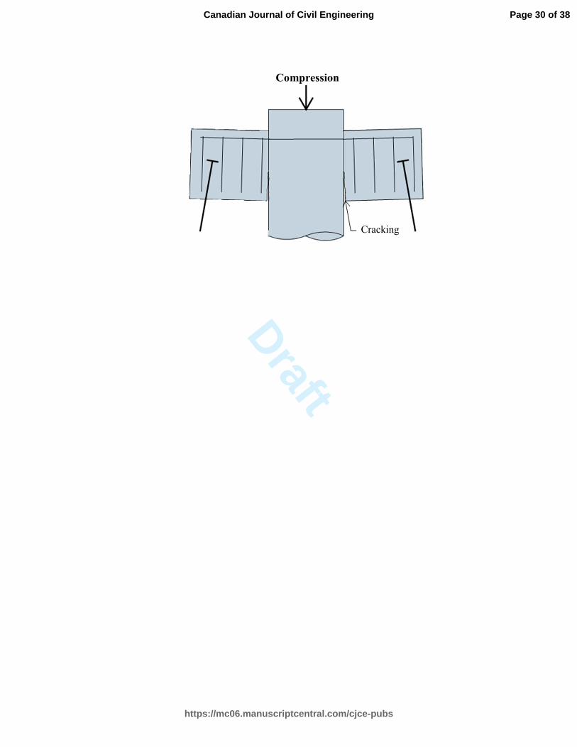
caisson had a factored compression resistance of 2550 kN. However, due to the load sharing, the
micro piles will carry a part of the total applied compression load and the cap beams will be
subjected to positive bending. If no reinforcement is provided at the bottom of the beams, the
system will develop a moment release under compression. This will result in cracking at the
lower segment of the interface, as shown in Fig. 7. For durability reasons, the positive bending
reinforcement is provided in this study. For this purpose, the micro piles were designed to have a
minimum compressive load capacity of 400 kN, and another strut-and-tie model was developed
with two micro pile reactions and the total leg compression applied to the existing caisson. The
analysis results indicated that 4-20M bars were sufficient at the bottom of the beams with a stress
ratio of 0.98. Once again, it is advisable to use 4-25M, given the negligible change in the
construction costs.
Crack Control Reinforcement
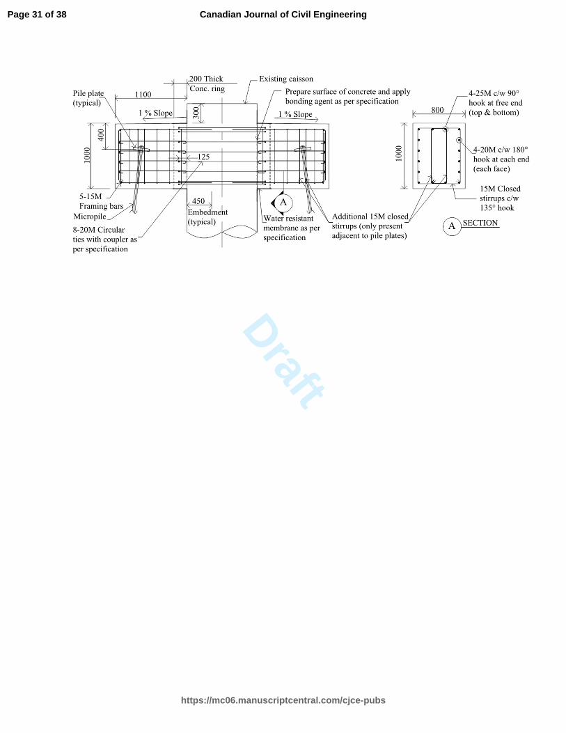
Minimum horizontal and vertical reinforcement should be placed near the side faces of
deep flexural members (see Clauses 10.6.2 and 11.4.5 of CSA A23.3-14). For the horizontal
reinforcement, four pairs of 20M bars were selected to provide the required 1200 mm2 of steel
per side with a maximum spacing of 200 mm. For the vertical reinforcement, two legs of 15M
bars with 250 mm spacing was used to provide the required reinforcement ratio of 0.002. A
closed stirrup was used for this reinforcement, which will also provide confinement and improve
the ductility. The resulting reinforcement arrangement is presented in Fig. 8.
Page 9 of 38
https://mc06.manuscriptcentral.com/cjce-pubs
Canadian Journal of Civil Engineering
Draft
10
Reinforcement Development at the Nodes
A critical requirement for the design of deep members is the anchorage of the
reinforcement. The tie reinforcement must be capable of resisting the calculated tension at all
nodes. For the model developed above, the use of closed stirrups ensured the full development of
the vertical 8-15M bars. For the main tension reinforcement of 4-20M, either a welded plate or a
standard 90° hook is required at Node 1 (in Fig. 5). A standard hook was employed in this study,
along with a concrete overhang of 400 mm beyond Node 1 to fully develop these bars.
The strut-and-tie model developed includes continuous horizontal tie reinforcement.
However, installation of continuous bars will not be possible in most cases due to the difficulty
in drilling through existing caissons without encountering one of the existing reinforcement bars
inside. One practical, and often used, solution is to employ discontinuous bars embedded into the
caisson with the use of epoxy adhesives. The embedment length required to develop the bond
strength is typically provided by an adhesive manufacturer, which was in the range of 250 mm
for the product that we selected. It should be noted that using the bond development length
recommended by a manufacturer will not ensure that the required bar tension can be successfully
carried. An additional reinforcing bar system is typically required to transfer the applied tension
to a support or other reinforcing bars. To achieve this transfer, supplementary hoop
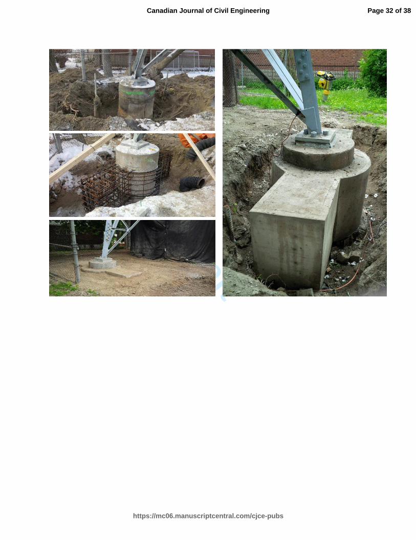
reinforcement was used in the proposed design. Due to the obstruction of the existing tower legs,
two half-circle hoops, connected with mechanical couplers, were employed. This required
enlarging the existing caisson diameter at the location of the new cap beams (see Fig. 9). It is
essential that a detailed analysis be undertaken to determine the required hoop quantity and
discontinuous bar embedment length. Nonlinear finite element analyses were undertaken for
these purposes.
Page 10 of 38
https://mc06.manuscriptcentral.com/cjce-pubs
Canadian Journal of Civil Engineering
Draft
11
Nonlinear Finite Element Modeling
A two-dimensional, continuum-type, plane-stress element was used for the finite element
modeling through a computer program, VecTor2 (Vecchio 2016). Other specialized analysis
programs, such as ATENA (Cervenka 2016) and WCOMD (Maekawa 2016), could also be used.
The constitutive model employed in VecTor2 is based on the Disturbed Stress Field Model
(Vecchio 2000), which is an extension of the Modified Compression Field Theory (Vecchio and
Collins 1986). This model employs a smeared, rotating crack approach within a total-load,
secant-stiffness solution algorithm. Tension stiffening effects were considered within the
constitutive models of the Disturbed Stress Field Model. Reinforcing bar response was modelled
using an elastic-plastic response, followed by a parabolic strain hardening phase according to the
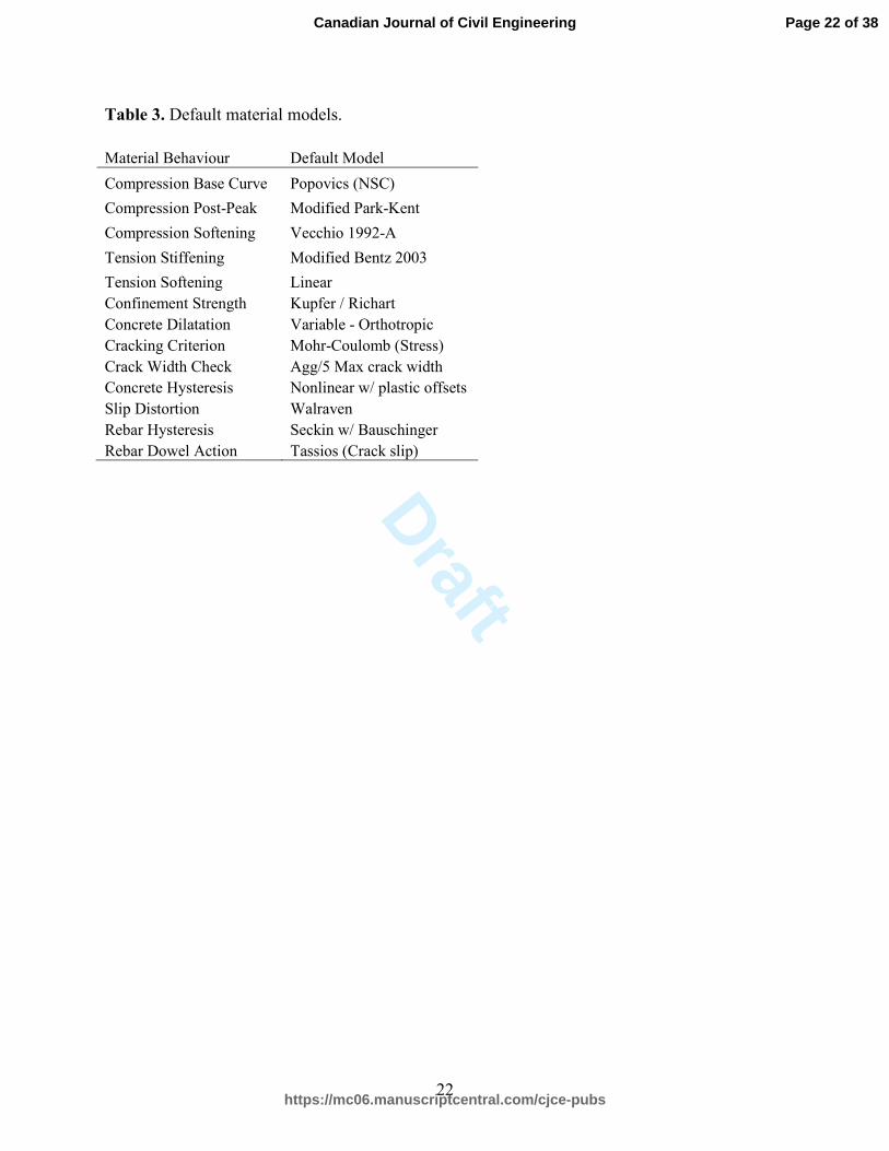
Seckin model (1981). Reinforcement dowel action was also considered. Throughout the
analyses, the default models were used for the material behaviours simulated as recommended by
Wong et al. (2013) (see Table 3).
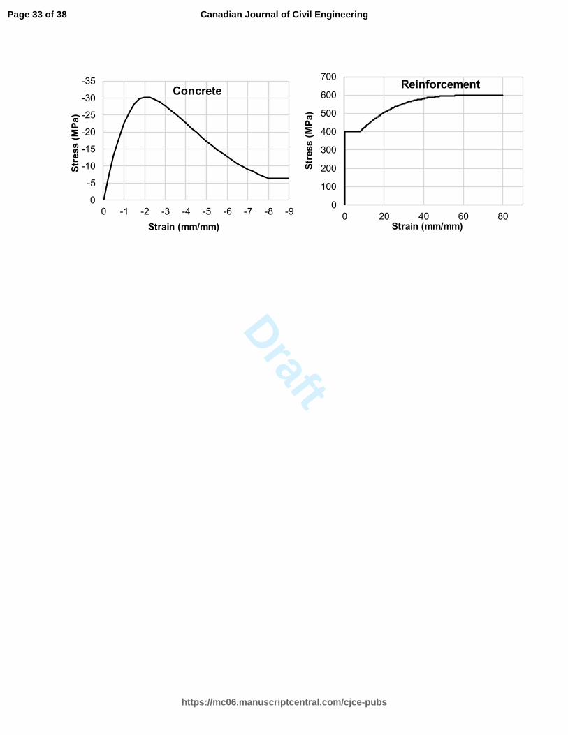
The only parameter required as input for the concrete modeling was the
compressive strength. The modulus of elasticity Ec, the strain ε0 corresponding to the peak stress
f’c, and the cracking stress tf ′ , were calculated by the program using the following equations
(Wong et al. 2013). The reinforcing bar properties were estimated for Grade 400 reinforcement.
The resulting stress-strain responses used in the analysis are shown in Fig. 10.
(1) '3300 6900 24,250 MPac cE f= + ≅
(2) '
31.95 101
c
c
f n
E nε −0
= ≅ ×
− where
'
0.8 2.4217
cfn = + =
(3) ' '0.33 1.73 MPat cf f= =
Page 11 of 38
https://mc06.manuscriptcentral.com/cjce-pubs
Canadian Journal of Civil Engineering
Draft
12
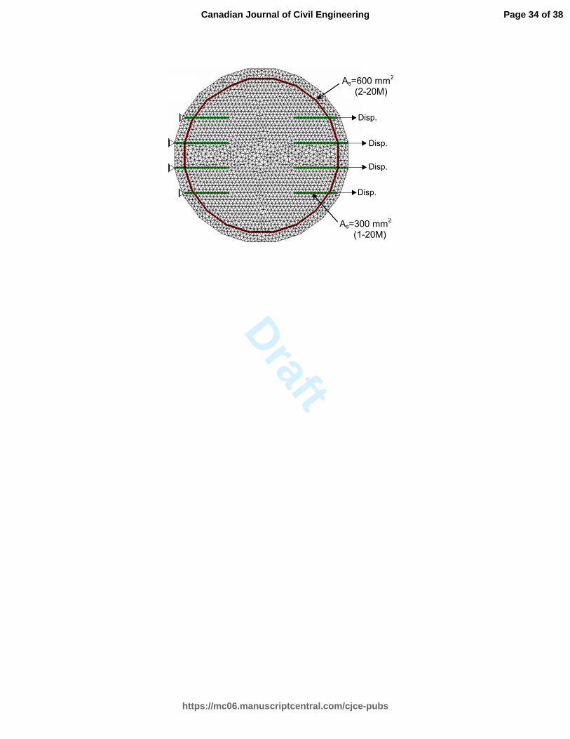
A finite element model was created using 3944 triangular elements (each with 6 degrees
of freedom and 150 mm thickness) and 2054 nodes. The discontinuous reinforcing bars and the
double-hoop reinforcement were modelled using perfectly-bonded discrete truss elements (each
with two degrees of freedom at each node). The model was restrained with four hinges on one
side, and the loading was applied uniformly on the other side with 0.1 mm displacement
increments. A displacement-controlled analysis was employed to obtain the post-peak response,
ductility, and failure mode. The finite element mesh is presented in Fig. 11.
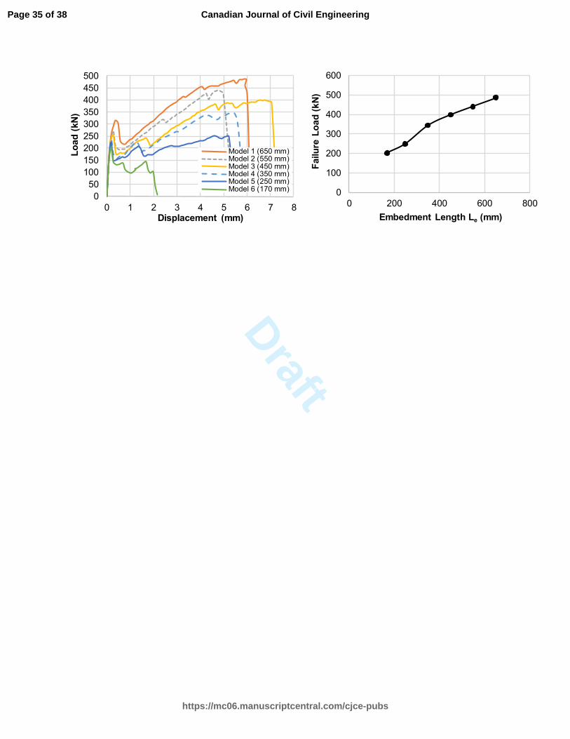
In order to determine the required embedment length for the discontinuous bars, six
different models were created by varying the embedment lengths: 650, 550, 450, 350, 250, and
170 mm for Models 1 to 6, respectively. The load-displacement responses and the failure loads
for all six models are presented in Fig. 12. The responses of Models 1 to 5 exhibited similar
behaviours: an initial peak load, followed by a sudden drop due to major cracking at the
termination of the reinforcement, and a stiffening response due to the activation of the
supplementary hoop reinforcement.
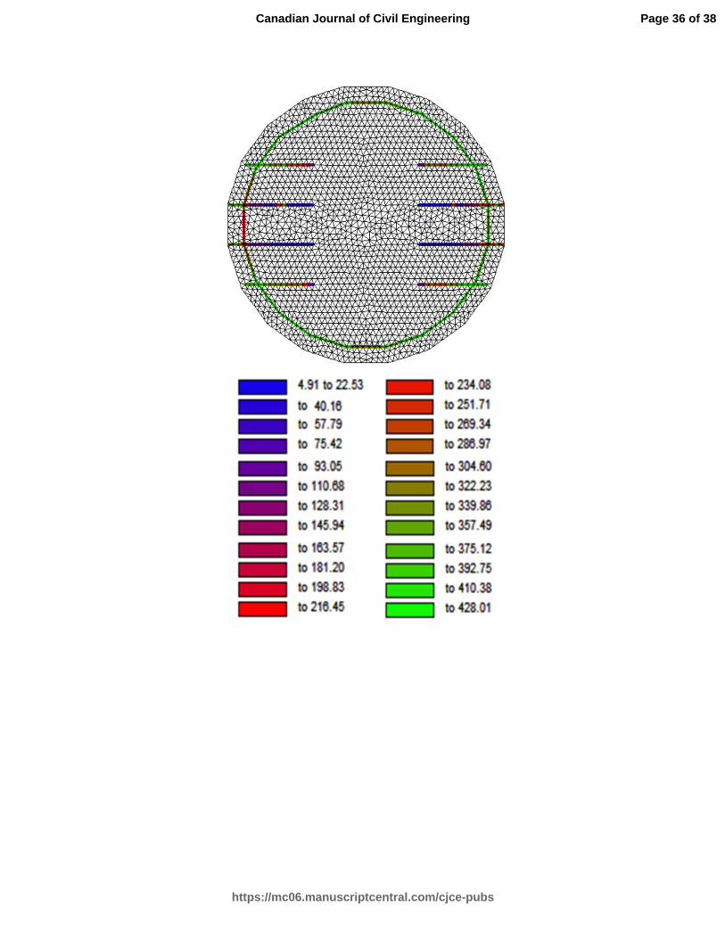
Analysis results indicated that the required minimum failure load of 400 kN was achieved
with an embedment length of 450 mm (Model 3). This model exhibited a ductile response
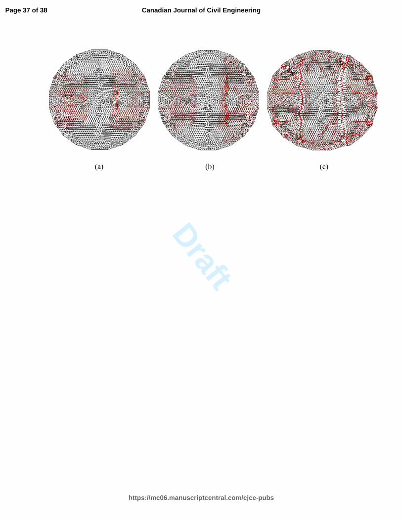
governed by the yielding of the supplementary hoop reinforcement (see Fig. 13). The three
stages of cracking are presented in Fig. 14.
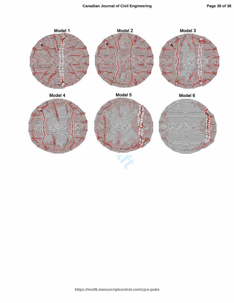
The change in the embedment length affected the load capacity and the failure mode of
the caisson significantly. The crack patterns for all models at failure are presented in Fig. 15. An
embedment length of 250 mm, which is recommended by the adhesive manufacturer, resulted in
an undesirable failure mode involving the local failure of concrete (see Fig. 15, Model 5). The
hoop steel was partially effective, and increased the load capacity by only 11% beyond the first
Page 12 of 38
https://mc06.manuscriptcentral.com/cjce-pubs
Canadian Journal of Civil Engineering
Draft
13
peak load (as compared to 55% in Model 1). The failure load obtained was 250 kN, which is
significantly lower than the required value of 400 kN. An embedment length of 170 mm, which
is less than the length recommended by the adhesive manufacturer, resulted in a brittle failure
upon first cracking at an applied load of 200 kN. This failure was the result of disintegration of
the concrete at the edge (see Fig. 15, Model 6). The hoops were ineffective in this model and did
not provide any increase in the load capacity. Note that the analysis uses perfectly bonded bars; a
possible bond slip may accompany this failure, making it even more undesirable.
Summary and Conclusions
Many existing self-supporting towers rely on caisson foundations for uplift resistance.
Increased demand for cellular antenna towers and public opposition to new towers in urban
centres, have driven the addition of antennas on existing towers. This increase in loads and more
stringent strength requirements in recent updates to design standards have required strengthening
of many existing caisson foundations. Although a number of retrofit schemes are commonly used
in practice, there is a lack of published guidelines for the proper analysis and design of the
retrofitted foundation systems. In this study, an analysis and design methodology was presented
for the strengthening of reinforced concrete caisson foundations for large uplift loads. Strut-and-
tie models were developed to verify the overall strength and integrity. Nonlinear finite element
analyses were undertaken to assess the performance and the failure mode at the micro level. The
proposed methodology was introduced with a case study involving an existing self-supporting
tower. The developed design drawings and construction pictures were also presented. The results
of the studies conducted support the following conclusions:
Page 13 of 38
https://mc06.manuscriptcentral.com/cjce-pubs
Canadian Journal of Civil Engineering
Draft
14
1. The addition of new structural elements is required to significantly increase the uplift
capacity of existing caisson foundations.
2. The capacity and behaviour of the retrofitted foundation must be verified by a numerical
analysis. The analysis must demonstrate that the connections between the new elements
and existing foundations are adequate to transfer the load.
3. A proper analysis method must be employed for deep beams using the strut-and-tie
methods and nonlinear finite element analyses. Simple sectional analysis methods with
simply-supported slender beam approaches are not valid for deep beams.
4. Special attention must be paid to the reinforcement development for deep members,
including simple support points. An overhang beyond the support points is required to
develop the reinforcing bars. T-headed bars or welded plates may also be employed if
there is limited space for such a beam overhang.
5. Providing the recommended bond development length for epoxy anchored bars does not
ensure that the bar tension can safely be carried. The designer must ensure that there are
adjacent rebars available (or designed) to transfer the tension load of the terminated bars
to a support point or other reinforcing bars.
6. Proper crack control reinforcement must be provided to ensure the long term durability of
deep beams. This typically requires using an orthogonal grid of reinforcing bars near each
face of deep beams.
7. The analysis and design process must be repeated for all possible load cases. Even
though the new elements are designed for uplift loads, they may be subjected to
significant compression loads due to load sharing.
Page 14 of 38
https://mc06.manuscriptcentral.com/cjce-pubs
Canadian Journal of Civil Engineering
Draft
15
8. The analysis and design methodology proposed in this study was numerically shown to
increase the uplift capacity of an existing caisson by a factor of 2.1. Overall behaviour,
ductility, and the failure mode of the retrofitted system were found to be satisfactory.
9. The proposed design has a general applicability and is suitable for applications where
there is limited space around the existing caissons.
Page 15 of 38
https://mc06.manuscriptcentral.com/cjce-pubs
Canadian Journal of Civil Engineering
Draft
16
Acknowledgements
The authors would like to thank Mr. Zane Biblow for his contributions to an earlier version
of the design proposed in this study. The authors would also like to acknowledge the contribution
of Sálvio Aragão Almeida Júnior, an undergraduate summer student funded by the Science
Without Borders Scholarship Program, for assisting in the finite element analyses presented in
this paper.
Page 16 of 38
https://mc06.manuscriptcentral.com/cjce-pubs
Canadian Journal of Civil Engineering
Draft
17
References
Abdalla, H.A. 2002. Assessment of damages and repair of antenna tower concrete foundations.
Construction and Building Materials. 16(8): 527–534.
Bruneau, M., Magued, M.H., and Dryburgh, R.B. 1989. Recommended guidelines for upgrading
existing towers. Canadian Journal of Civil Engineering. 16(5): 733–742.
Cervenka, V. 2016. ATENA: Software for nonlinear analysis of reinforced concrete structures
[online]. Prague, Czech Republic. Available from http://www.cervenka.cz [accessed 18 January
2016].
CSA. 2014. Design of concrete structures. CSA standard CSA A23.3. Canadian Standards
Association (CSA). Mississauga, ON, Canada. 290 pp.
CSA. 2013. Antennas, towers, and antenna-supporting structures. CSA standard S37-13.
Canadian Standards Association (CSA). Mississauga, ON, Canada. 216 pp.
CSA. 2001. Antennas, towers, and antenna-supporting structures. CSA standard S37-01.
Canadian Standards Association (CSA). Mississauga, ON, Canada. 118 pp.
CSA. 1994. Antennas, towers, and antenna-supporting structures. CSA standard S37-94.
Canadian Standards Association (CSA). Mississauga, ON, Canada. 105 pp.
Faridafshin, F., and McClure, G. 2008. Seismic response of tall guyed masts to asynchronous
multiple-support and vertical ground motions. ASCE Journal of Structural Engineering. 134(8):
1374-1382.
Kumalasari, C., Ding, Y., Madugula, M.K.S., and Ghrib, F. 2006. Compressive strength of solid
round steel members strengthened with rods or angles. Canadian Journal of Civil Engineering.
33(4): 451–457.
Page 17 of 38
https://mc06.manuscriptcentral.com/cjce-pubs
Canadian Journal of Civil Engineering
Draft
18
Maekawa, K. 2016. WCOMD: Nonlinear analysis program of reinforcement concrete structures
[online]. University of Tokyo, Japan. Available from http://www.forum8.co.jp/english/uc-
win/wcomd-e.htm [accessed 18 January 2016].
Magued, M.H., Bruneau, M., and Dryburgh, R.B. 1989. Evolution of design standards and
recorded failures of guyed towers in Canada. Canadian Journal of Civil Engineering. 16(5): 725–
732.
Seckin, M. 1981. Hysteretic behavior of cast-in-place exterior beam-column-slab assemblies.
Ph.D. thesis, Department of Civil Engineering, University of Toronto, ON, Canada.
Selby, R.G., and Dryburgh, R.B. 1996. A comparison of the gust factor method and the patch
load method of analysis of guyed towers. Canadian Journal of Civil Engineering. 23(4): 862–
871.
Tjhin, T., and Kuchma, D. 2004. CAST: Computer-aided strut and tie analysis software. Version
0.9.11. University of Illinois at Urbana-Champaign, IL, USA.
Vecchio, F.J. 2016. VecTor2: Nonlinear finite element analysis software for reinforced concrete
structures [online]. Version 2.9. University of Toronto, ON, Canada. Available from
http://www.civ.utoronto.ca/vector/ [accessed 18 January 2016].
Vecchio, F.J. 2000. Disturbed stress field model for reinforced concrete: formulation. ASCE
Journal of Structural Engineering. 126(8): 1070-1077.
Vecchio, F.J., and Collins, M.P. 1986. The modified compression field theory for reinforced
concrete elements subject to shear. ACI Structural Journal. 83(2): 219-231.
Wahba, Y.M.F., Madugula, M.K.S., and Monforton, G.R. 1994. Limit states design of antenna
towers. Canadian Journal of Civil Engineering. 21(6): 913–923.
Page 18 of 38
https://mc06.manuscriptcentral.com/cjce-pubs
Canadian Journal of Civil Engineering
Draft
19
Wong P.S., Vecchio F.J., and Trommels, H. 2013. VecTor2 and FormWorks user’s manual.
Technical Report, Department of Civil Engineering, University of Toronto, ON, Canada.
Page 19 of 38
https://mc06.manuscriptcentral.com/cjce-pubs
Canadian Journal of Civil Engineering
Draft
20
Table 1. Geotechnical resistance factor, φ, for constant-width caissons.
S37-94 S37-01 S37-13
φ 0.75 0.375 0.5
Utilization 100% 200% 150%
Page 20 of 38
https://mc06.manuscriptcentral.com/cjce-pubs
Canadian Journal of Civil Engineering
Draft
21
Table 2. Strength reduction parameters and material properties.
Concrete
Struts 0.85
f'c (MPa) 30
Steel Ties 1.00φc fy (MPa) 400
CCC Nodes 0.85mφc As
CCT Nodes 0.75mφc 4-20M (mm
2) 1200
CTT Nodes 0.65mφc 5-#9 (mm
2) 3225
Page 21 of 38
https://mc06.manuscriptcentral.com/cjce-pubs
Canadian Journal of Civil Engineering
Draft
22
Table 3. Default material models.
Material Behaviour Default Model
Compression Base Curve Popovics (NSC)
Compression Post-Peak Modified Park-Kent
Compression Softening Vecchio 1992-A
Tension Stiffening Modified Bentz 2003
Tension Softening Linear
Confinement Strength Kupfer / Richart
Concrete Dilatation Variable - Orthotropic
Cracking Criterion Mohr-Coulomb (Stress)
Crack Width Check Agg/5 Max crack width
Concrete Hysteresis Nonlinear w/ plastic offsets
Slip Distortion Walraven
Rebar Hysteresis Seckin w/ Bauschinger
Rebar Dowel Action Tassios (Crack slip)
Page 22 of 38
https://mc06.manuscriptcentral.com/cjce-pubs
Canadian Journal of Civil Engineering
Draft
23
List of Tables
Table 1. Geotechnical resistance factor, φ, for constant-width caissons.
Table 2. Strength reduction parameters and material properties.
Table 3. Default material models.
List of Figures
Fig. 1. Loads resisted by self-supporting tower foundations.
Fig. 2. Commonly used retrofit schemes for caisson foundations overloaded in uplift.
Fig. 3. Self-supporting tower examined.
Fig. 4. Caisson foundation to be strengthened.
Fig. 5. Strut-and-tie model for uplift loads.
Fig. 6. Strut-and-tie analysis results for uplift loads.
Fig. 7. Expected cracking under compression loads in the absence of bottom reinforcing bars.
Fig. 8. Reinforcement details of the proposed design.
Fig. 9. Construction pictures of the proposed design.
Fig. 10. Concrete and reinforcement uniaxial response.
Fig. 11. Finite element model.
Fig. 12. Load and deflection results for different embedment lengths.
Fig. 13. Reinforcing bar stresses for Model 3 (in MPa).
Fig. 14. Crack patterns for Model 3: (a) at the first peak, (b) at the load drop, and (c) at failure.
Fig. 15. Crack patterns at failure for different embedment lengths.
Page 23 of 38
https://mc06.manuscriptcentral.com/cjce-pubs
Canadian Journal of Civil Engineering
Draft
Local loads
on caissons
Overturning
moment
Axial load
(compression or uplift)
Shear load
Shear
load
Self-supporting
tower
Wind
loading
Axial load
Page 24 of 38
https://mc06.manuscriptcentral.com/cjce-pubs
Canadian Journal of Civil Engineering
Draft
New concrete
slab and anchors
– tied into
existing caisson
with dowels
New concrete block
– tied into existing
caisson with dowels New concrete
beam and caissons
– tied into existing
caisson with dowels
Existing
concrete
caisson
Existing
concrete
caisson
Existing
concrete
caisson
Page 25 of 38
https://mc06.manuscriptcentral.com/cjce-pubs
Canadian Journal of Civil Engineering
Draft
Page 26 of 38
https://mc06.manuscriptcentral.com/cjce-pubs
Canadian Journal of Civil Engineering
Draft
Page 27 of 38
https://mc06.manuscriptcentral.com/cjce-pubs
Canadian Journal of Civil Engineering
Draft
Page 28 of 38
https://mc06.manuscriptcentral.com/cjce-pubs
Canadian Journal of Civil Engineering
Draft
Page 29 of 38
https://mc06.manuscriptcentral.com/cjce-pubs
Canadian Journal of Civil Engineering
Draft
Compression
Cracking
Page 30 of 38
https://mc06.manuscriptcentral.com/cjce-pubs
Canadian Journal of Civil Engineering
Draft
Page 31 of 38
https://mc06.manuscriptcentral.com/cjce-pubs
Canadian Journal of Civil Engineering
Draft
Page 32 of 38
https://mc06.manuscriptcentral.com/cjce-pubs
Canadian Journal of Civil Engineering
Draft
-35
-30
-25
-20
-15
-10
-5
0
-9-8-7-6-5-4-3-2-10
Stress (MPa)
Strain (mm/mm)
Concrete
0
100
200
300
400
500
600
700
0 20 40 60 80
Stress (MPa)
Strain (mm/mm)
Reinforcement
Page 33 of 38
https://mc06.manuscriptcentral.com/cjce-pubs
Canadian Journal of Civil Engineering
Draft
As=600 mm2
(2-20M)
As=300 mm2
(1-20M)
Page 34 of 38
https://mc06.manuscriptcentral.com/cjce-pubs
Canadian Journal of Civil Engineering
Draft
0
50
100
150
200
250
300
350
400
450
500
0 1 2 3 4 5 6 7 8
Load (kN)
Displacement (mm)
Model 1 (650 mm)Model 2 (550 mm)Model 3 (450 mm)Model 4 (350 mm)Model 5 (250 mm)Model 6 (170 mm) 0
100
200
300
400
500
600
0 200 400 600 800
Failure Load (kN)
Embedment Length Le (mm)
Page 35 of 38
https://mc06.manuscriptcentral.com/cjce-pubs
Canadian Journal of Civil Engineering
Draft
Page 36 of 38
https://mc06.manuscriptcentral.com/cjce-pubs
Canadian Journal of Civil Engineering
Draft
(a) (b) (c)
Page 37 of 38
https://mc06.manuscriptcentral.com/cjce-pubs
Canadian Journal of Civil Engineering
Draft
Page 38 of 38
https://mc06.manuscriptcentral.com/cjce-pubs
Canadian Journal of Civil Engineering