Embed Size (px)
Citation preview

SD 27: Buena Vlsca Yards DRAFT 02. l 1.02
I. Introduction
Intent The following guidelines are meant to establish the appropriate standards for build~ngs and sveeucapes throughout the Buena V~sta Yards Neighborhood. These standards will guide future designs towards a high level of design qualiq and thought
Guidelines BuenaVlscaYards should funct~on as the mid-town hub of Miami. Its connections t o the Design D i s t r t c ~ the Wynwood neighborhood, and Biscayne Boulevard should make theyards an integral part o f the a m , design, and retail community.
The Urban Design Standards for the SD 27 Overlay District create rwo sub-overlay districts w h ~ c h divides the BuenaVistaYards into rwo activity zones: SD 27.1 and SD 27.2. These classifications are used t o describe rwo different sets of minlmum, required design standards in the BuenaVistaYards neighborhood.

SD 17: Buena Vista Yards D M F T 02.1 1.02
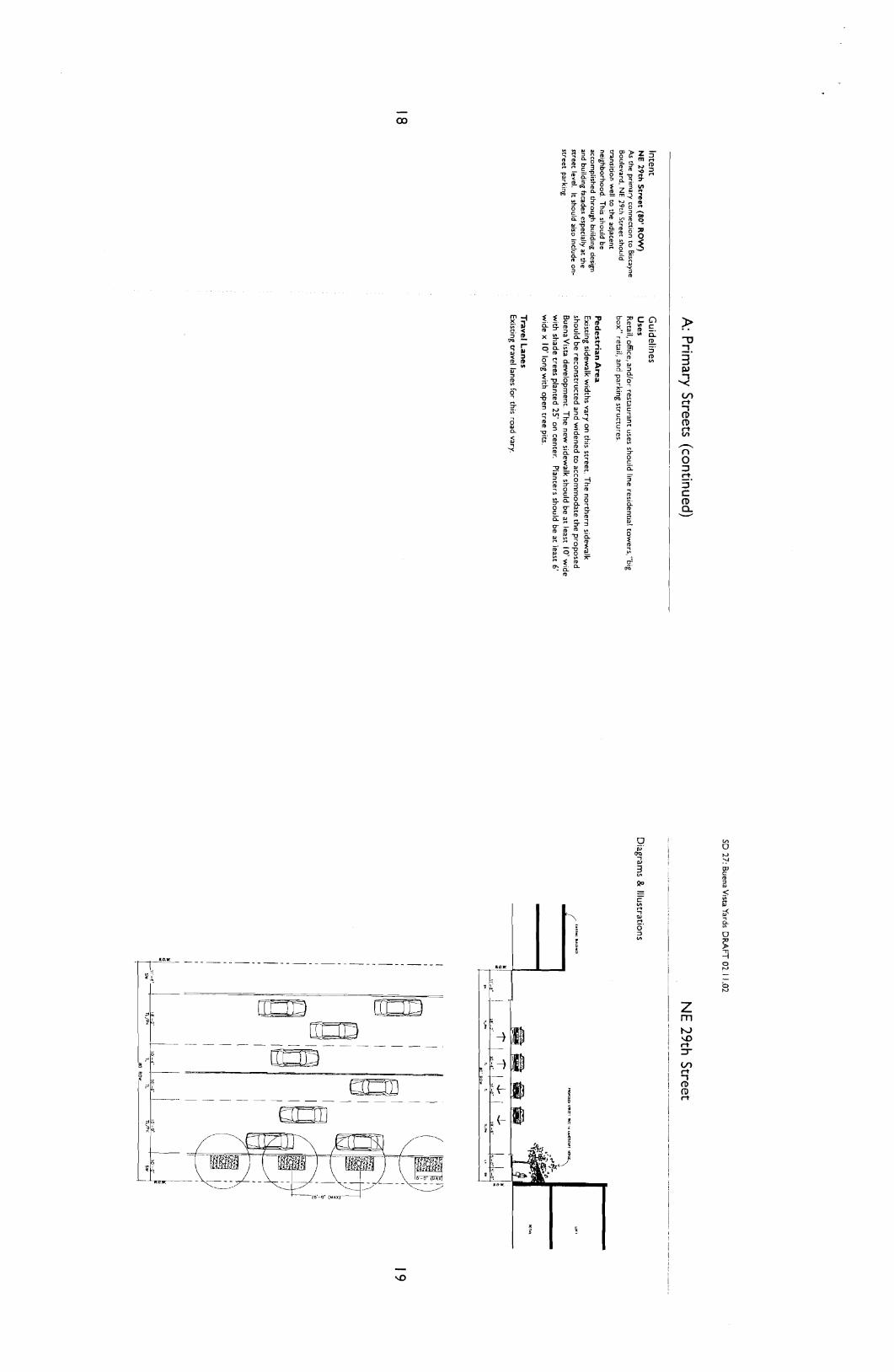
Intent The primary streetr In the BuenaVista Yards are the main activity zones and should be designed to respond to the pedestrians' needs. This 1s most irnpomnt a t the street level, which will contribute to the neighborhood's success as a "place".
N E 34th Street (90' R O W ) N E 34th Sweet should serve ar. the main retail corridor and a prominent
Wansporetion connection to the Wynwood neighborhood. Landscaped med~ans should enhance pedeswian crossings to encourage sweet level actlv~ties.
A: Primary Streets
Guidelines Uses Retail, enterralnment, oflice, andior restaurant uses should line residential towers, hotels, and parking structures Additionally, "big box" retail is permitted as a ground floor use.
Pedestr ian A r e a Sidewalks on NE 34th Street should have a minimum 10' wide walkable area with adequate shade trees.
Shade trees should be planted 30' on center, in a square open tree p i r The tree pit should be benveen 8.5' and 12' long with a I' wide x 6" high curb and a continuous bed of shrubs.
Light poles located in thls area should be evenly spaced 90' on center along this verge in between the proposed shade trees.
A continuous 2' stepping verge is recommended at the back o f curb.A I' wide urban curb wtth a I ' wide gucter should be placed between the stepping verge and the parking area.
Paral le l Park ing A continuous r o w of parallel parking spaces is recommended benveen the travel lane and the landscape verge area with corner bulb-ouu. A 2' wide valley gucter should separate the park~ng area from the travel lane.
Travel Lanes The travel lanes for this road will be I I ' wlde.
Medians The median width should be I I' with a standard FDOT cype "F" curb. Planting along the median should consist o f large palm trees placed a maximum o f 25' on center. Ground level planting should hang over the curb. Utilize pedestrian refuges and traf ic rate bollards at all intersection except Market Streer Bollards should be spaced t o meetADA require- menu.
NE 34th Street ~ . . ~ ~ . .~ -~
Diagrams & Illustrations

SD 27: Buena Vista Yard: D M F T 02.1 1.02
Intent North Miami Avenue (70' ROW) A 12 ft dedrcauon will be enoblrshed whlch will Increase the 70 f t ROW roo 82 f t RGW
k the major perimeter sweet for the BuenaVise rail yards. North Miami Avenue should have a seamless vansition to the Wynwood neighborhood. The sweetrape and building design should incorporate several characteristics of the existlng condition in order w achieve a good transition. Add~tionally, North Miami Avenue should have an arcade to create a pleasant pedestrian environment that IS consistent with the character of the retail corridor and will a t t rac t activity into the core of the neighborhood. The median on N o d Mlaml Avenue will create a
srronger connection for pedesv~anr walking from the Wynwood neighborhood.
A: Primary Streets (continued)
Guidelines Uses The predominant use on Nor th Miami Avenue 1s "blg box"
Pedestrian Area Sidewalks on Norch M~ami Avenue should have a minimum 5' walkable area and a 7' parallel parking1 landscape verge.
Royal palms (Roystonea elata) should be planted in at least 7' x 5' landscape areas that are flush with the sidewalk. Palms must be setback 3.5' from the curb as per County mandates and be planted a t least every two on-street parking spaces. Additionally, a bed of shrubs should be planted in the area between the palm and the back of curb.
Parallel Parking A continuous r o w of parallel parking spaces is recommended between the travel land and the landscape verge area with corner bulb-ours. Standard type "F" curbs are recommended.
Travel Lanes The travel lanes for thls road should be I I' wide.
Medians The median width should be 10' wlth a standard FDOT type "F" curb. Planting along the median should consist o f Roystonea elata placed a maximum o f 25' on center. Ground level planting should hang over the curb. Urilize pedestrian refuges and traf ic rare bollards at all intersection except Market Street. Bollards should be spaced t o meetADA requirements.
North Miami Avenue
Diagrams & Illustrations

SD 27: Buena Vista Yards DRAFT 02.1 1.02
Intent Market Street (90' ROW) curbless
m e t Market Street w~ l l be the maln pedesrr~an zone and will have the abil~ry to be closed to traffic for spec~al events. Ir IS located one block of NE l sr Avenue adjacent to the publ~c plaza and will be closed ro truck trafic.
B: Secondary Streets (continued)
Guidelines Uses Retail, office, ne~ghborhood retail, and/or restaurant uses should l~ne residential towers, hotel,"b~g box" retail, of ice towers, and park~ng structures.
Pedestrian Area Sidewalks on Market Street should have a 9' wide walkable area with a landscape verge. One Washingconia robusta, with ground level planting should be planted in each 8' x 8' raised planters. The planters should be centered bemeen every t w o parallel parking spaces with a I ' wide by 6" h~gh curb. Each Washingconia should have a clear trunk, which matches the overall height o f the shade trees along the corr idor at installation.
Material for this area should be brick o r concrete pavers. Paving colors and patterns must be kept consistent throughout the corridor t o enhance the connectivity of the space.
Parallel Parking A n 8' wide parallel parking area should be separated, every m o parking spaces by ah 8' x 8' raised planter, rotated 45 degrees, with a I ' wide x 6" high curb on all sides. This rotauon will make i t easier for cars t o pull in and ou t o f parking spaces. One Delonix regla is recommended In
each planter wich ground level planting around the base.
Materials for this area should match that o f the pedestrian area. Thermoplastic striping o r paint should n o t be used along t h ~ s corridor, rather striplng for the parallel parking should be a white colored paver,
Travel Lanes The travel lanes for this road will be I 2 f t wide wi th materials that match the pedestrian and parallel parking areas for continuity. Al l necessary vehicular striping should be done wi th colored pavers rather chan Thermoplasuc striping o r painr
Medians A 16' wide median is recommended w i th alternating 12' x 12' raised planters and a pedestrian area flush w l th the rest o f the streer The planter should have a I ' wide by 18" high seatlng wall wrapping it on all s~des. This wall may be constructed o f reinforced concrete,granite o r an alternative approved material.
A 2' wide coarse grained, verge should be left clear of obstructions along che edge of each travel lane on either side of che median. This will provide a more definable separation between the travel lane and the pedestrian oriented median. Examples of such materials are: river r o c k cobble stone, pavers. Such material should be mortared set. Materials for the remainder of the median should match the rest o f the StPeet
One Delonix regia is recommended at the center o f each planter, with ground level planting around the base.
Market Street _ -.-_p~--.---_...._.-p... - -- . .
Diagrams & Illustrations
90 PO*
The space between the planters should have cwo benches and m o trash receptacles, and t w o lighted bollards.
SD 27: Buena V~sta Yards DRAFT 02.1 1.02
C: Tertiary Streets (continued) --
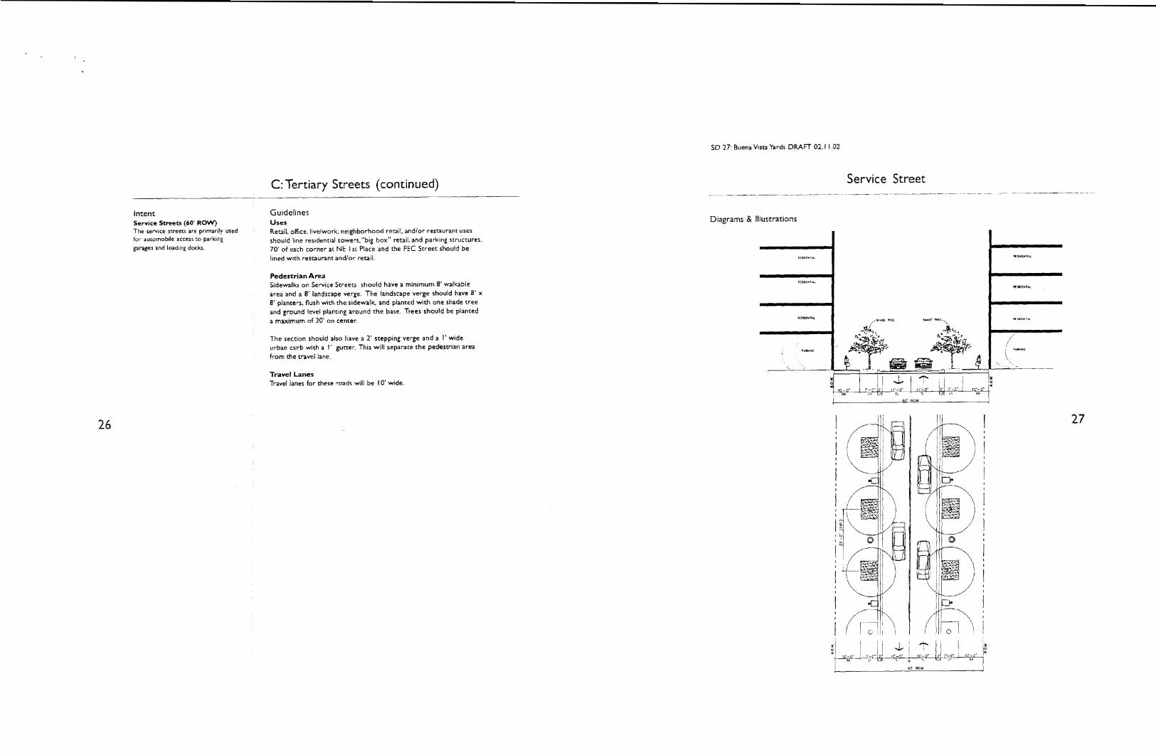
Intent Guidelines Service Streets (60' ROW) Uses The service sweets are pr~rnarily used Retail, office, livdwork, neighborhood retail, and/or restaurant uses for automobile access to parking should llne residential towers,"big box" retail. and parking structures garages and loading docks. 70' of each corner at N E I st Place and the FEC Street should be
lined with restaurant andior retail.
Pedestrian Area Sidewalks on Service Streets should have a minimum 8' walkable area and a 8' landscape verge. The landscape verge should have 8' x 8' planters, flush with the sidewalk, and planted wi th one shade tree and ground level plant~ng around the base. Trees should be planted a maximum of 20' on center.
The section should also have a 2' stepping verge and a I' wide urban curb with a I ' guner. This wil l separate the pedestrian area from the travel lane
Travel Lanes Travel lanes for these roads will be 10' wide
Service Street .- ~~- . - ~- ~
Diagrams & illustrations
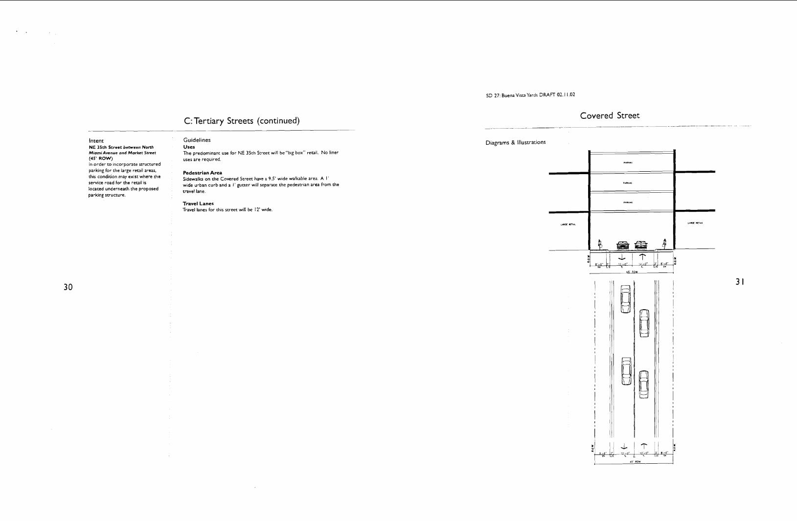
Intent NE 35th Street between Nonh Miami Avenue ond Market Srreet (45' ROW) In order t o incorporate structured parking for the large retail areas, this condition may exist where the service road for the retail is located underneath the proposed parking structure.
C: Tertiary Streets (continued)
Guidelines Uses The predominant use for N E 35th Street will be "big box" retail. N o liner uses are required
Pedestrian Area Sidewalks on the Covered Street have a 9.5' wide walkable area. A I ' wide urban curb and a I' gutter will separate the pedestrian area from the travel lane.
Travel Lanes Travel lanes for this street will be 12' wide.
Covered Street _ _ _ ~ -_
Diagrams & Illustrations
4s ROW 1

SD 27: Buena Vism Yards DRAFT 02.1 1.02
Intent Create a comfortable scale for the Buena Vista Yards neighborhood by balancing building heights, setbacb, and massings with sweet and sidewalk widths.
Establish NE 1st Place and NE 34th Street as main streets using greater building heights and different setback.
Emphas~ze the inrersection of North Miami Avenue and NE 36th Street as a
gateway to the Design Dlswin with greater building heights.
1.1 Height: Utilize vatying building heights and floor heights to achieve a comfortable pedeswian scale to enhance BuenaVista Yards as a v i bnn~ urban, community. Building heights help to achieve this environment by enclosing a space to
reinforce an urban neighborhood 34 character.
1.2 Setbacks Enforce build~ng setbacb that respond to the sweet w~dth and the building height ih order to achieve a comfortable, outdoor room. Varying setback help create different outdoor spaces with narrow streets and comlortable spaces between buildings on opposite sides of the street
I. Building Scale
Standards SD 27.1 I. I Height The parking podium for all mlxed- use buildings is I~mited to l 10' in height Residential towers on the FEC Street are limited t o 300' in height except on the south corners of 34th and 36th Streets which may build up to 350' in heighr
1.2 Setbacks Buildings on NE 1st Place have no setback requirements for the first 120' of building heighr Above 120' the building must be setback a minimum of 70'.
Buildings at the intersection of NE I s t Place and NE 34th Street have no setbacks for towers.
Residential uses on mews have 20' setback requiremenu for the first 25' of building heighr Above 25' of building heighk residential buildings on mews must be setback 35'. Above 70', residential towers have a minimum setback require- ment of 55' from the centerline of the sweet
Buildings on the FEC Street have a zero minimum setback for the first 70'. Above 70' of building he igh~ residential towers have a minimum setback of 10'. Additionally, a maximum of 40% of the building frontage on major corridors and perimeter streeu may have no setback requirements.
SD 27.2 I. I Height All streeu have a maximum building height of 60' on North Miami Avenue except for buildings at the intersection of North Miami Avenue and NE 36th Street which have a maximum height of 80'.
Buildings on NE I st Place have a maximum building height of 80' except for the towers on the Market Street Plaza which have a maximum building height of 200'.
1.2 Setbacks All streets will have zero minimum setbacks except for Nbrth Miami Avenue and NE 36th Street
Buildings on North M~ami Avenue and NE 36th Street should have a min~mum front setback of 9 feet from the edge of the property line for the ground floor. The "front" refers to building frontage on all sweets.
Arcades are required for buildings fronting North Miami Avenue and N.E. 36th Street (See part North Miami Avenue description.)
Buildings on the west side of NE 1st Place, south of NE 34th St ree~ should have a 20' setback If a colonnade is not provided, a minimum setback of 4' is required.
Buildings have no setback require- menu for the first 60' of heighr Above 60', the building tower must be setback 50'.
Building Scale - - ~~ _ _ _-_- ._ ~ _ _ _.
Diagrams & Illustrations
Similar Drawing
SD 27: Buena Vista Yards DRAFT 02. l 1.02
2. Building Facade (continued)
Intent Standards 2.3 Scal~ng Elements: S D 27.1 S D 27.2 Encourage vaned arch~tectural 2.3 Scaling E lements 2.3 Scaling Elements elements on rhe lower levels of Large, blank surfaces are d~scour- Large,blank surfaces are dlscour- bulld~ng facades to create Imporrant aged unless they have a cornpelllng aged unless they have a compell~ng v~sual Interest for pedestrtans and des~gn purpose Non-modular des~gn purpose Non-modular avo~d und~fferent~ated blank walls
materials such as concrete panels mater~als such as concrete panels
U~ilize muluple repetiuve features to and stucco, require extra ground and stucco, require extra ground
create an architectural rhythm. floor level detail. floor level detail.
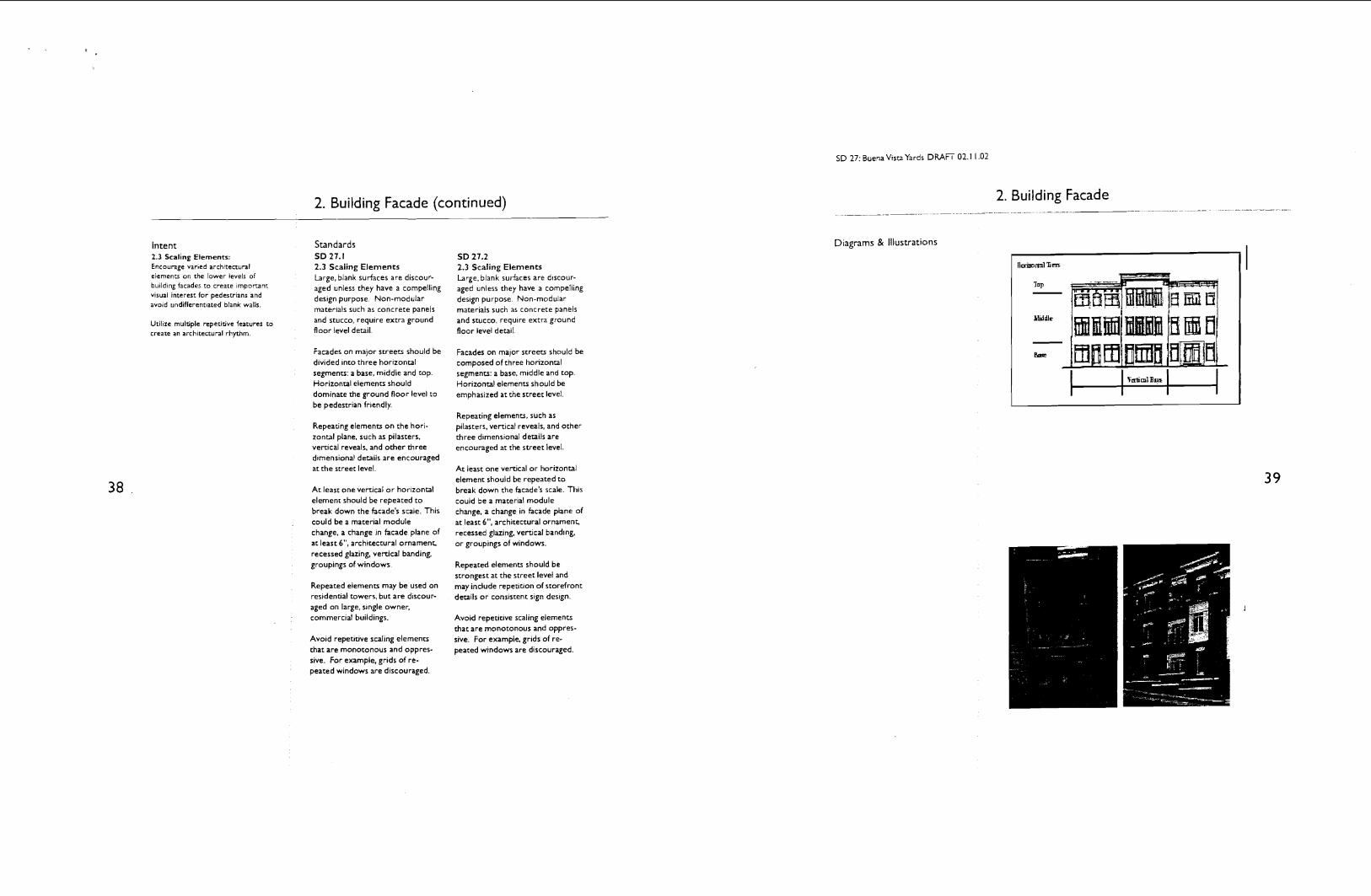
Facades on major streets should be Facades on major streets should be divided into three horizontal composed of three horizontal segments: a base, middle and top. segments: a base, middle and top. Horizonral elements should Horizontal elements should be dominate the ground floor level to emphasized at the street level. be pedestrian fr~endly.
Repeating elements, such as Repeating elements on the hori- pilasters, vertical reveals, and other zontal plane, such as pilasters, three dimensional details are vertical reveals, and other three dlmensional details are encouraged at the street level.
A t least one vertical o r horizontal element should be repeated t o break down the facade's scale. This could be a material module change, a change in facade plane of at least 6". architectural ornamenG recessed glazing, vertical banding, groupings of windows.
Repeated elemenu may be used on
encouraged at the street level
A t least one vertical o r horizontal element should be repeated t o break down the facade's scale. This could be a material module change, a change in facade plane of at least 6", architectural ornamenG recessed glazing, verucal band~ng, o r groupings of windows.
Repeated elements should be strongest at the street level and may include repetition o f storefront
residential towers, but are discour- deLils o r consistent sign design. aged on large, slngle owner, commercial buildings. Avoid repetitive scaling elements
that are monotonous and oppres- Avoid repetitive scaling elements sive. For example, grids of re- that are monotonous and oppres- peated windows are discouraged. sive. For example, grids of re- peated windows are discouraged.
2. Building Facade ~ - ~ . - ._---.._pp .. -
Diagrams & Illustrations
SD 27: Buena Vista Yards DRAFT 02.1 1.02
3. Articulation - - - -
Intent Standards Storefronu and entrances should be SD 27.1 articulated d~Kerently because they 3. I Entrances create an Interplay between the publlc Entr~es should be arrlculated wlth and prtvate reaim and Interlor and exterlor actlvltles S~m~larly, facades dlfferent bu~ldlng mater~als,
des~gn should reflec: a bu~ld~ng's changes in bulld~ng massing, o r
~nter~or act~v~ues and spaual changes In the roof llne that break
arrangemenu Therefore, false the facade's regulated surface Thls bu~ld~ng fronu that obscure the creates a h~erarchy on the bulld~ng lnternal scale and functlon of bulldlnp facade so that entrances are most are d~scounged prominent
3.1 Entrances: Enhanced lighting and signage Emphasize street level envies for a
legible hierarchy in building facades. should also be incorpopated in the entry design.
Bulldlngs should have muluple entry polnts along the street t o reflect the dlfferent tnterlor uses Addlt~onally, publlc entrances must be prov~ded on all s~des of a buildlng wlth street frontage except when corner entrances are prov~ded
Corner entrances should be des~gned t o address street corners. Th~s may Include addlt~onal buildlng mass, d~stlnct~ve archltec- tural elements, d~fferent buildlng mater~als, changes In buildlng planes, and changes In buildlng shape
All building entrances should be transparent
Entrances should be setback from the primary building frontage at least 6".
Large banks of glass doors at main entrances should be used t o break down expansive building facades.
SD 27.2 3.1 Entrances Entr~es should be an~culated w ~ t h dlfferent bu~ldlng mater~als, changes In bulldlng rnasslng. o r changes In the roof llne that break the facade's regulated surface Thts creates a h~erarchy on the build~ng facade so that entrances are most promlnent
Enhanced l~ghting and signage should also be incorporated in the entry des~gn.
Buildings should have multiple entry points along the street t o reflect the different interior uses. Additionally, public entrances musr be provided on all s~des of a building with street frontage except when corner entrances are provided.
Corner entrances should be designed t o address street corners. This may include add~tional build~ng mass, distinctive architec- tural elements, different building materials, changes in building planes, and changes in building shape.
All building entrances should be vansparent
Entrances should be setback from the primary building frontage at least 6".
Large banks of glass doors at main entrances should be used t o break down expansive building facades.
3. Articulation .. ~ . - -. - ~
Diagrams & Illustrations

6. Signage
Intent Standards Exter~or storefront slgns should help SD 27.1 SD 27.2 create character for the 6.1 Genera l Guidel ines 6.1 Genera l Guidel ines neighborhood, while conveying clear A mln~mal number of slgns should Three types of s~gns are permitted and concise ~nfotmation about the
be used t o avoid clutter and ~n BuenaVisca Yards Metal channel businesses they serve. Well designed signs are effect~ve tools to enhance excessive information. Similarly, letters fixed directly t o building
storefronts and attract people signs should be simple and convey walls are permitted, as well as . . basic information such as the store projecting signs, and neon and
6.1 General Guidelines: name and street number. Slgns should be simple and minimal, but they should also be creat~ve. 6.2 Channe l Le t te rs
Signs composed of channel letters 6.2 Channel Letters: are preferred t o other, wall Use channel lettering for storefront slgns, whenever possible. mounted signs because they
provide information in a clear and clean manner. Use contrasting colors for lettering and wall color. Additionally, lettering should be scrlpt o r stylized.
S~gns should be located In the storefront frame o r above the awnlng, dlrectly above the store's enuance.
LED type-signs for med~a uses.
In general, signs should be in proportion with the building's scale. They should also be legible at the pedestrian scale. Therefore, a combination of large and small scale slgns may be used.
A minimal number of signs should be used t o avoid clutter and excessive informatioh. Similarly, signs should be simple and convey basic information such as the store name and street number.
6.2 Channe l Le t te rs Signs composed of channel letters are preferred t o other, wall mounted signs because they provide informauon in a clear and clean manner. Use contrasting colors for lettering and wall color. Additionally, lettering should be scrlpt o r stylized.
Signs should be located in the storefront frame o r above the awning, directly above the store's entrance.
Lettering may be raised from the build~ng facade t o cast shadows on the building surface.
Diagr
en;
--.
&
Sra
--
JSt
6. Signage
There is n o limit on lettering size.
SD 27. Bucna Vista Yards DRAFT 02.1 l .O2
7. Building Tops and Roof Tops
Intent Roof tops and buildlng tops should be atvacrlve from t h e s v e e t level and from resldenttal towers
7.1 BuildingTops: Utilize distinctive buildlng tops to tdenvfy the area as midtown Mtami.
7.2 Parking Garage Roof: Conceal roof top parklng
7.3 RoofTops: Rooftops should be arrracuve and should be veated as pan of the building facade.
Standards SD 27.1 7.1 Bui ld ing Tops Residentrai towers should have distinctive building tops whenever possible.
7.2 Park ing Garage Roof Uncovered parking garage roofs should be concealed with creative, colored surfaces and landscaping.
7.3 RoofTops All roof top equipment must be concealed.
SD 27.2 7.1 Bui ld ing Tops Resldentlal towers should have dlstlnctlve build~ng tops whenever possible.
7.2 Park ing Garage Roof Uncovered parking garage roofs should be concealed wlth creattve, colored surfaces and landscap~ng.
7.3 RoofTops All roof top equipment must be concealed.
Green roofs o r roof tops planted Green roofs o r roof tops planted with heat tolerant, low mainte- with heat tolerant, low rnainte- nance weeds, or cultivated plant nance weeds, o r cultivated plant life are strongly encouraged. liie are strongly encouraged.
Recreational uses are encouraged Recreational uses are encouraged on roof tops. on roof tops.
8. Building Tops and RoofTops - -- - . - . ._ .. , .. _ . - . _
Diagrams & Illustrations
MIAMI SKYLINE