Embed Size (px)
Citation preview

Draft
TC 42 ORIGINAL TC 42 REVISED AS PER IS 12169-1987 ABSTRACT OF IS CODECOMMENTS (if
any)
1 GENERAL 1.0 GENERAL
A large number of small embankment dams are
being designed by the local design office and
built in the state. In designing a small
embankment dam, use of IS 8826-1978
(Guidelines for design of large earth and Rock-
fill dams) is made. This sometimes, results in
uneconomical and unwarranted provisions in
design. It is therefore, felt necessary that a
separate Technical Circular should be available
for guiding the design of a small embankment
dam in the state.
A large number of small embankment dams are
being designed by the local design office and
built in the state. In designing a small
embankment dam, use of IS 8826-1978
(Guidelines for design of large earth and Rock-fill
dams) is made. This sometimes, results in
uneconomical and unwarranted provisions in
design. It is therefore, felt necessary that a
separate Technical Circular should be available
for guiding the design of a small embankment
dam in the state. Previously issued Design
series T.C. No-42 is now revised in view to
adding details not-furnished before.
1.1 Small Earth Dam 1.1 Small Earth Dam
An earth dam may be termed as a small earth dam
if it fulfils all the following criteria :
An earth dam may be termed as a small earth
dam if it fulfils all the following criteria;
Madhya Pradesh Water Resources Department
Design Series Technical Circular No. 42
Guidelines for design of small Earth Dams
if it fulfils all the following criteria : dam if it fulfils all the following criteria;
1. Its height is less than 15m above the deepest
riverbed level;
1. Its height is less than 15 m above the deepest
river bed level
2. The volume of earthwork involved in dam
construction is less than 0.75 million meter cube;
2. The volume of earthwork involved in dam
construction is less than 0.75 million meter cube
3. Storage created by the embankment is less than
one million meter cube; and
3. Storage created by the embankment is less
than one million meter cube
4. The maximum flood discharge from the-
intercepted catchment area is less than 2000
cumec.
4. The maximum flood discharge from the-
intercepted catchment area is less than 2000
cumecs.
2.0 . SCOPE 2.0 SCOPE
This technical circular-provides guidelines to design
a small earth dam.
This technical circular-provides guidelines to
design a small earth darn. This TC is based on
IS: 12169 – 1987 (Reaffirmed 2013).
3.0 TERMINOLOGY 3.0 TERMINOLOGY
For the purpose of this circular, following definitions
shall apply:-
For the purpose of this circular, following
definitions shall apply:-
3.1 Casing or Shell: — All, zones other than
core in a zonal earth dam are called Casing.
3.1 Casing or Shell: - All zones other than core
in a zonal earth dam are called casing.

3.2 Core: — A zone of impervious earth within
azoned earth dam.
3.2 Core: - A zone of impervious earth within a
zoned earth dam.
3.3 Cut-off: — A barrier of impervious ,-material
provided in foundation of a dam, to reduce
seepage of water through foundation and
abutments.
3.3 Cut-off: - A barrier of impervious material
provided in foundation of a dam, to reduce
seepage of water through foundation and
abutments.
3.4 Edging:- A short protection on the
downstream edge of the top width of dam.
3.4 Edging: - A short protection on the
downstream edge of the top width of dam.
3.5 Embankment Dam: — A dam composed of
any type of soil including rock
3.5 Embankment Dam: - A dam composed of
any type of soil including rock.
3.6 Free board: — The vertical distance between
the top, bund level of an embankment and the
maximum reservoir water level.
3.6 Free board: - The vertical distance between
the top bund level of an embankment and the
maximum reservoir water level.
3.7 Full Reservoir-Level (FRL): - It is the highest
level of the reservoir at which water is intended
to be held for various uses including part or
total of the flood storage without allowing any
passage of water through spillway.
3.7 Full Reservoir-Level (FRL): - It is the highest
level of the reservoir at which water is intended
to be held for various uses including part or total
of the flood storage without allowing any passage
of water through spillway.
3.8 Homogeneous Earth Dam: - An embankment
dam composed of single type of material
3.8 Homogeneous Earth Dam: - An
embankment dam composed of single type of
material.
3.9 Horizontal Filter:- A layer of uniform or 3.9 Horizontal Filter: - A layer of uniform or 3.9 Horizontal Filter:- A layer of uniform or
graded pervious material placed within body of
the dam horizontally
3.9 Horizontal Filter: - A layer of uniform or
graded pervious material placed within body of
the dam horizontally.
3.10 Impervious Blanket or Clay Blanket:- An
upstream impervious soil layer of specified
thickness laid over a relatively pervious stratum
and connected to the core.
3.10 Impervious Blanket or Clay Blanket:- An
upstream impervious soil layer of specified
thickness laid over a relatively pervious stratum
and connected to the core.
3.11 Impervious Strata: - The strata having
range of permeability similar to core material.
3.11 Impervious Strata: - The strata having
range of permeability similar to core material.
3.12 Inclined/Vertical Filter Or Chimney Filter - A
layer of uniform or graded perviousmaterial
placed inclined/vertical in the body of the dam.
3.12 Inclined / Vertical Filter Or Chimney
Filter: - A layer of uniform or graded pervious
material placed inclined/vertical in the body of the
dam.
3.13 Inner Cross Drain:- A trench filled with filter
material to collect seepage from inner
longitudinal drain and carry it to toe drain.
3.13 Inner Cross Drain:- A trench filled with filter
material to collect seepage from inner
longitudinal drain and carry it to toe drain.

3.14 Inner Longitudinal Drain:- A trench filled with
filter material and laid along the down stream toe of
the core of dam to collect seepage from core of the
dam.
3.14 Inner Longitudinal Drain:- A trench filled
with filter material and laid along the downstream
toe of the core of dam to collect seepage from
core of the dam.
3.15 Lowest Water Level (LWL) or Minimum
Draw Down Level (MDDL): - The lowest level to
which a reservoir may be lowered keeping in view
the requirements for hydropower generation or
irrigation and other needs.
3.15 Lowest Water Level (LWL) or Minimum
Draw Down Level (MDDL): - The lowest level to
which a reservoir may be lowered keeping in
view the requirements for hydropower generation
or irrigation and other needs.
3.16 Maximum Water Level (MWL): It is the
highest level to which the reservoir water will rise
while passing the design flood with the spillway
facilities in full operation.
3.16 Maximum Water Level (MWL): - It is the
highest level to which the reservoir water will rise
while passing the design flood with the spillway
facilities in full operation.
3.17 Pore-pressure: - The pressure developed in
the air-water fluid within the voids of the soil mass
under external force when drainage is prevented.
3.17 Pore-pressure: - The pressure developed
in the air-water fluid within the voids of the soil
mass under external force when drainage is
prevented.
3.18 Relief Well: - Vertical wells or bore holes,
downstream of or in down stream shoulder of an
earth dam, to collect and control seepage through
or under the dam so as to reduce water pressure.
3.18 Relief Well: - Vertical wells or bore holes
downstream of or in downstream shoulder of an
earth dam, to collect and control seepage
through or under the dam so as to reduce water
pressure.
3.19 Rip-Rap: - It is a protection to an
embankment material against erosion due to wave
3.19 Rip-Rap: - It is a protection to an
embankment material against erosion due to embankment material against erosion due to wave
action, velocity of flow, rain wash, wind action etc.,
provided by placing a protection layer of rock
fragments or manufactured material.
embankment material against erosion due to
wave action, velocity of flow, rain wash, wind
action etc., provided by placing a protection layer
of rock fragments or manufactured material.
3.20 Rock-toe Boulder toe: - A zone of free
draining material comprising of rock fragments I
boulders / cobbles etc., provided at the toe of the
dam.
3.20 Rock-toe/Boulder toe: - A zone of free
draining material comprising of rock fragments /
boulders / cobbles etc., provided at the toe of the
dam.
3.21 Sudden Draw-Down: - The rate of lowering of
reservoir water level which does not allow full
dissipation of pore pressure simultaneously with the
lowering of the reservoir water level.
3.21 Sudden Draw-Down: - The rate of lowering
of reservoir water level which does not allow full
dissipation of pore pressure simultaneously with
the lowering of the reservoir water level.
3.22 Toe Drain: - A trench filled with filter material
or without it along the downstream toe of an earth
dam to collect seepage from horizontal filter and
lead it to natural drain.
3.22 Toe Drain: - A trench filled with filter
material or without it along the downstream toe of
an earth dam to collect seepage from horizontal
filter and lead it to natural drain.

3.23 Turfing: - it is a cover of grass grown over
downstream slope of an embankment to prevent
erosion of soil particles by rain-wash and wind
action.
3.23 Turfing: - It is a cover of grass grown over
downstream slope of an embankment to prevent
erosion of soil particles by rain-wash and wind
action.
3.24 Zoned Or Zonal Earth Dam: - An earth dam
composed of zones of different types of soils.
3.24 Zoned Or Zonal Earth Dam: - An earth
dam composed of zones of different types of
soils.
4 CLASSIFICATION 4. CLASSIFICATION
Based on materials used in construction, an earth
dam can be classified as hereunder: -
Based on materials used in construction, an
earth dam can be classified as here under: -
4.1 Homogeneous Dam: - As defined in para-3.8
above.
4.1 Homogeneous Dam: - As defined in para-
3.8 above.
4.2 Zoned Or Zonal Earth Dam: - As defined in
para-3.24 above.
4.2 Zoned Or Zonal Earth Dam: - As defined in
para-3.24 above.
4.3 Modified Homogeneous Embankment
Dam : - An embankment dam in which small
quantities of pervious material, selected to
control the action of seepage, are carefully
placed in an otherwise homogeneous dam.
IS CODE 12169-1987 (REAFFIRMED 2003)
Para-2.3.1
Modified Homogeneous Embankment Dam:
- An embankment dam in which small
quantities of pervious material, selected to
control the action of seepage, are carefully
placed in an otherwise homogeneous dam.
4.4 Rockfill Dam : - An embankment consisting
of various sizes of rock to provide stability and
an impervious core of membrane to provide
IS CODE 12169-1987 (REAFFIRMED 2003)
Para-2.4
Rockfill Dam: - An embankment consisting of an impervious core of membrane to provide
water tightness.
Rockfill Dam: - An embankment consisting of
various sizes of rock to provide stability and an
impervious core of membrane to provide water
tightness.
5 FUNCTIONS AND DESIGN REQUIREMENTS
OF DIFFERENT COMPONENTS OF THE DAM
5 FUNCTIONS AND DESIGN REQUIREMENTS
OF DIFFERENT COMPONENTS OF THE DAM
5.1 Components Components
Different components of an earth dam may be
listed as below:-
Different components of an earth dam may be
listed as below:-
i) Core or hearting i) Core or hearting
ii) Casing or shell ii) Casing or shell
iii) Internal drainage arrangement iii) Internal drainage arrangement and
foundations
iv) Slope protections iv) Downstream Inclined Filter/Vertical Filter
v) Edging v) Edging (Rock Toe)
vi) impervious or clay blanket vi) Toe Drain
vii) Cut-off (puddle trench) vii) Out Fall Drain
viii) Relief wells. viii) Slope protections

ix) Downstream drainage arrangements. ix) Downstream drainage arrangements(Undre-
Seepage Control measures)
x) Cut-off /Puddle trench.
The following components are provided in
special cases:
i) Relief Wells
ii) Impervious or clay blanket
5.2 Core Or Hearting 5.1 Core Or Hearting
Core is a zone of impervious earth and provides an
impermeable barrier within the body of the dam.
Core is a zone of impervious earth and provides
an impermeable barrier within the body of the
dam. Impervious soils are generally suitable for
the core. IS: 1498-1970+ may be referred to for
suitability of soils for the core. Appendix A gives
recommendation based on IS: 1498-1970+.
However, soils having high compressibility and
liquid limit and having organic content may be
avoided, if possible, as they are prone to
swelling and formation of cracks.
IS CODE 12169-1987 (REAFFIRMED 2003)
Para 4.2.1
Core is a zone of impervious earth and
provides an impermeable barrier within the
body of the dam. Impervious soils are
generally suitable for the core. IS: 1498-1970+
may be referred to for suitability of soils for the
core. Appendix A gives recommendation
based on IS: 1498-1970+. However, soils
having high compressibility and liquid limit and
having organic content may be avoided, if
possible, as they are prone to swelling and
formation of cracks.
5.2.1 Location Of Core 5.1.1 Location Of Core
For small dams core should be centrally located. For small dams core should be centrally located.
The core may be located either centrally or
IS CODE 12169-1987 (REAFFIRMED 2003)
Para 4.2.2 The core may be located either centrally or
inclined upstream. The locations will depend
mainly on the availability of materials,
topography of site, foundation conditions,
diversion considerations, etc. The main
advantage of a central core is that it provides
higher pressure at the contact between the core
and the foundation reducing the possibility or
leakage and piping. On the other hand, inclined
core reduces the pore pressure in the
downstream part of the dam and thereby
increases its safety. It also permits the
construction or downstream casing ahead of the
core. The section with an inclined core allows
the use of relatively large volume of random
material on the downstream side.
Para 4.2.2
The core may be located either centrally or
inclined upstream. The locations will depend
mainly on the availability of materials,
topography of site, foundation conditions,
diversion considerations, etc. The main
advantage of a central core is that it provides
higher pressure at the contact between the
core and the foundation reducing the
possibility or leakage and piping. On the other
hand, inclined core reduces the pore pressure
in the downstream part of the dam and thereby
increases its safety. It also permits the
construction or downstream casing ahead of
the core. The section with an inclined core
allows the use of relatively large volume of
random material on the downstream side.
5.2.2 Dimensions Of Core 5.1.2 Dimensions Of Core
Following considerations govern the core
thickness:-
Following considerations govern the core
thickness:-
i) Availability of suitable impervious material for
core;
i) Availability of suitable impervious material for
core;
ii) Resistance to piping; ii) Resistance to piping;
iii) Permissible seepage through dam; iii) Permissible seepage through dam;
iv) Availability of other material for casing, filter etc., iv) Availability of other material for casing, filter
etc.,
Minimum width that will permit proper
construction.
IS CODE 12169-1987 (REAFFIRMED 2003)
Para 4.2.3 e)
Minimum width that will permit proper
construction.
In general, slopes of central core are to be provided
as 1:1 on both upstream and downstream.
However, depending upon availability of core
material, slopes may be provided steep up to
1/2(H): 1(V) after satisfying the property
requirement of core material and recording reasons
for the same.
In general, slopes of central core are to be
provided as 1:1 on both upstream and
downstream. However, depending upon
availability of core material, slopes may be
provided steep up to 1/2(H): 1(V) after satisfying
the property requirement of core material and
recording reasons for the same.5.2.2.1 Top Width Of Core 5.1.2.1 Top Width Of Core
It should be provided as 3m minimum. It should be provided as 3 m minimum. The
thickness of the core at any section shall not
be less than 30 percent (preferably not lesser
than 50 percent) of maximum head of water
acting at that section.
IS CODE 12169-1987 (REAFFIRMED 2003)
Para 4.2.3
The thickness of the core at any section shall
not be less than 30 percent (preferably not
lesser than 50 percent) of maximum head of acting at that section. lesser than 50 percent) of maximum head of
water acting at that section.
5.2.2.2 Top Level Of Core 5.1.2.2 Top Level Of Core
For small earth dams, the top level of the core be
provided at a level equal to MWL+0.5m.
For small earth dams, the top level of the core be
provided at a level equal to MWL + 0.5 m.
5.2.2.3 Suitable Core Material 5.1.2.3 Suitable Core Material

To determine suitability of soil as core material, its
testing is necessary. Soil groups generally suitable
for core construction are indicated in Annexure-1.
Specifically, soils having permeability less than 10-5
cm/second, Plasticity Index (P.1.) >15, clay content
>30% and liquid limit between 30 to 50% are
suitable for core construction. To avoid swelling
tendencies the P.1 shall not exceed 30. Soils
having P1 less than 10 may have dispersive
qualities and should be used with utmost care.
Impervious soils are generally suitable for core.
IS: 1498-1970 may be referred to for suitability of
soils for the core . To determine suitability of soil
as core material, its testing is necessary. Soil
groups generally suitable for core construction
are indicated in Annexure-1. Specifically, soils
having permeability less than 10-5 cm/second,
Plasticity Index (P.I.) >15, clay content >30% and
liquid limit between 30 to 50% are suitable for
core construction. To avoid swelling tendencies
the P.I. shall not exceed 30. Soils having P.I. less
than 10 may have dispersive qualities and
should be used with utmost care. However, soils
having high compressibility and liquid limit and
having organic content may be avoided, if
possible, as they are prone to swelling and
formation of cracks.
IS CODE 12169-1987 (REAFFIRMED 2003)
Para 4.2.1
However, soils having high compressibility and
liquid limit and having organic content may be
avoided, if possible, as they are prone to
swelling and formation of cracks.
5.3 Casing Or Shell 5.2 Casing Or Shell
On outer side of core, a cover of relatively pervious
soil is provided. This protects the core from external
damages such as erosion from the rainwater,
weathering and also under conditions of sudden
draw down and steady seepage. Shell helps core to
On outer side of core, a cover of relatively
pervious soil is provided. This protects the core
from external damages such as erosion from the
rainwater, weathering and also under conditions
of sudden draw down and steady seepage. Shell draw down and steady seepage. Shell helps core to
retain its moisture content and thus prevents cracks
in it.
of sudden draw down and steady seepage. Shell
helps core to retain its moisture content and thus
prevents cracks in it.
5.3.1 Casing Material 5.2.1 Casing Material
The relatively pervious soils are suitable for casing.
These are not subject to cracking on direct
exposure to atmosphere and are relatively free
draining. Soil groups suitable for casing are shown
in Annexure-l. Soils with coefficient of permeability
greater than 10 -2cm/second develop no pore
pressure and are free draining. Moorum is a casing
soil.
The relatively pervious soils are suitable for
casing. These are not subject to cracking on
direct exposure to atmosphere and are relatively
free draining. Soil groups suitable for casing
based on IS:1489-1970 are shown in Annexure-
l. Soils with coefficient of permeability greater
than 10-2 cm/second develop no pore pressure
and are free draining. Moorum is a casing soil.
5.3.2 Top Width 5.2.2 Top Width

Top width for small earth dam should be kept
minimum as 4.5m uniformly throughout the length
of the dam. Surface drainage of crest should be
provided by sloping the crest in a grade of 1 in 50
to drain towards upstream. The design series
technical circular (T.C.) No. 10 " Crest Width of
Earth / Rock fill Dams" should be referred for the
purpose.
The width of the dam at the crest should be fixed
according to the working space required at the
top. Top width for small earth dam should be
kept minimum at 4.5 m uniformly throughout the
length of the dam. Surface drainage of crest
should be provided by sloping the crest in a
grade of 1 in 50 to drain towards upstream. The
design series technical circular (T.C.) No. 10
"Crest Width of Earth / Rock fill Dams" should be
referred for the purpose.
5.3.3 Slope And Section 5.2.3 Slope And Section
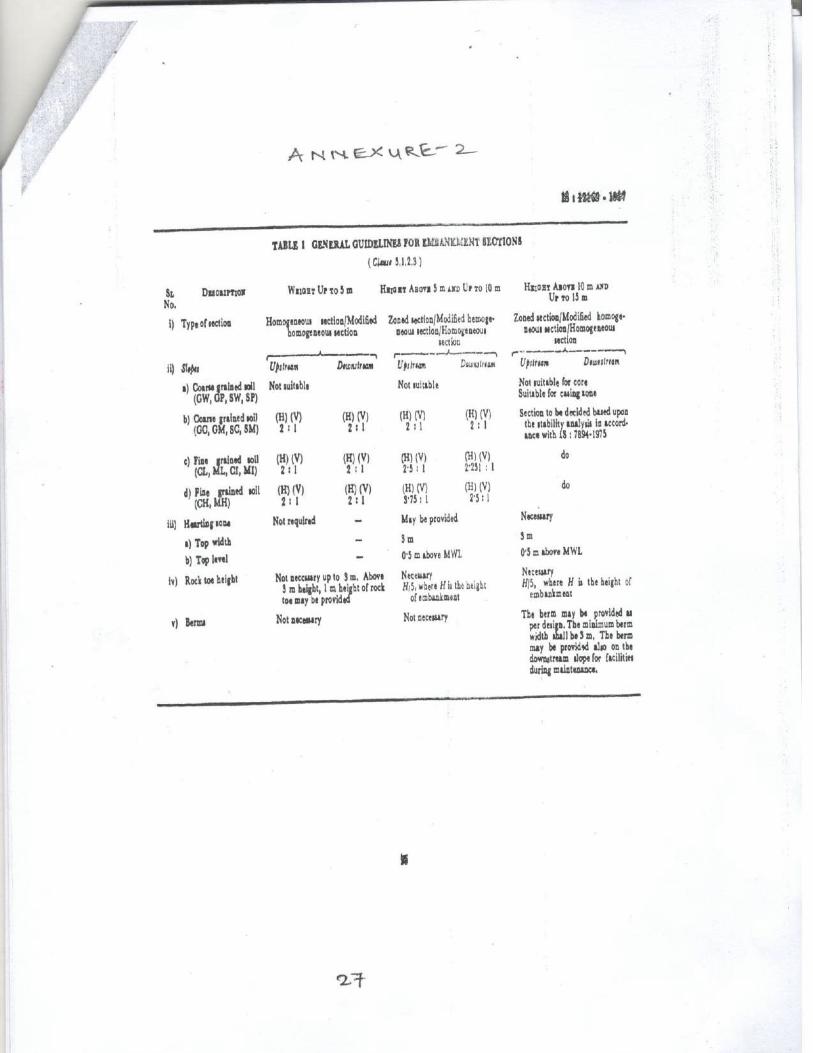
The slopes of casing depend upon soil properties.
General guidelines for embankment section are
recommended in Annexure-II.
The slopes of casing depend upon soil
properties. General guidelines for embankment
section are recommended in Annexure-II.
5.3.4 Free Board 5.2.4 Free Board
The objective of free-board is to provide assurance
for safety of the am against overtopping due to
inflows into the reservoir, wind set up, wave run up, ,nd slides, seismic activities, extreme settlement of
the embankment and/or its foundation. For
computation of free board, design series technical
circular No.22 issued by BODHI may be referred-to.
Minimum free board to be adopted is 2m.
The objective of free-board is to provide
assurance for safety of the dam against
overtopping due to inflows into the reservoir,
wind set up, wave run up, ,and slides, seismic
activities, extreme settlement of the embankment
and/or its foundation. For computation of free
board, design series technical circular (T.C.) No
.22 issued by BODHI may be referred to. Minimum free board to be adopted is 2m. .22 issued by BODHI may be referred to.
Minimum free board to be adopted is 2 m.
5.3.5 Shrinkage And Settlement Allowance 5.2.5 Shrinkage And Settlement Allowance
Shrinkage and settlement allowance shall be
provided: -
Shrinkage and settlement allowance shall be
provided: -
i) For dams founded on rock: - The allowance shall
be provided at a rate of 1% of the height of the
dam.
i) For dams founded on rock: - The allowance
shall be provided at a rate of 1% of the height of
the dam.
ii) For dams founded on soil or compressible
foundation, the allowance shall be considered as
2% of the height of the dam.
ii) For dams founded on soil or compressible
foundation, the allowance sha be considered as
2% of the height of the dam.
The shrinkage allowance is to be computed on
above guidelines for various heights i.e. wherever
there is a berm or change of slope and also for top
bund level of the dam. These points should be
raised vertically by the magnitude of shrink age
allowance to be provided. The points so obtained
shall be joined starting from original base width.
The shrinkage allowance is to be computed on
above guidelines for various heights i.e.
wherever there is a berm or change of slope and
also for top bund level of the dam. These points
should be raised vertically by the magnitude of
shrinkage allowance to be provided. The points
so obtained shall be joined starting on original
base width.5.4 Internal Drainage Arrangement 5.3 Internal Drainage Arrangement
An internal drainage arrangement helps in safe
passage of seeping water. This arrangement as far
as, possible shall be provided with locally available
sand and gravel. The arrangement comprises as
hereunder: -
An internal drainage arrangement helps in safe
passage of seeping water. This arrangement as
far as, possible shall be provided with locally
available sand and gravel. For the design of the
components of the internal drainage system
IS:9429-1980 may be referred to .
The design of filter consists applying the
conventional filter criteria which take into
account only the grain size distribution and the
shape of the grains. However, in addition to the
grain size, the stability of the base soil adjacent
to a given filter depends on its resistance to drag
forces.
IS CODE 12169-1987 (REAFFIRMED 2003)
Para 4.4.2 The
design of filter consists applying the
conventional filter criteria which take into
account only the grain size distribution and the
shape of the grains. However, in addition to
the grain size, the stability of the base soil
adjacent to a given filter depends on its
resistance to drag forces. resistance to drag forces. In view of this, when the soil containing 20
percent or more clay is used as a basse soil and
has non-dispersive properties, the filter criteria
may not be enforced strictly and the clean sand
available locally may be used irrespective of the
gradation. This relaxation should be applied to
dams upto 10 m height only. For dams of height
more than 10 m, the criteria for filters protecting
cohesive soil may be relaxed by the designer
depending upon his judgement and experience.
The arrangement comprises as here under :
IS CODE 12169-1987 (REAFFIRMED 2003)
Para 4.4.2
In view of this, when the soil containing 20
percent or more clay is used as a basse soil
and has non-dispersive properties, the filter
criteria may not be enforced strictly and the
clean sand available locally may be used
irrespective of the gradation. This relaxation
should be applied to dams upto 10 m height
only. For dams of height more than 10 m, the
criteria for filters protecting cohesive soil may
be relaxed by the designer depending upon his
judgement and experience.
5.4.1 Horizontal Filter 5.3.1 Horizontal Filter (Base Filter)
This filter is provided in the downstream portion of
the dam. It collects seepage from chimney filter,
body of the dam and also from its foundation and
leads seepage, thus collected, to the downstream
toe drain.
This filter is provided in the downstream portion
of the dam. It collects seepage from chimney
filter, body of the dam and also from its
foundation and leads seepage, thus collected, to
the downstream toe drain.
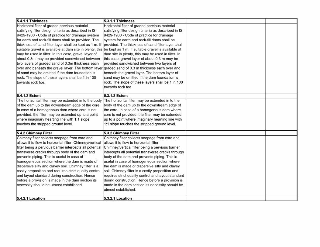
5.4.1.1 Thickness 5.3.1.1 Thickness
Horizontal filter of graded pervious material
satisfying filter design criteria as described in IS:
9429-1980 - Code of practice for drainage system
for earth and rock-fill dams shall be provided. The
thickness of sand filter layer shall be kept as 1 m. If
suitable gravel is available at dam site in plenty, this
may be used in filter. In this case, gravel layer of
about 0.3m may be provided sandwiched between
two layers of graded sand of 0.3m thickness each
over and beneath the gravel layer. The bottom layer
of sand may be omitted if the dam foundation is
rock. The slope of these layers shall be 1 in 100
towards rock toe.
Horizontal filter of graded pervious material
satisfying filter design criteria as described in IS:
9429-1980 - Code of practice for drainage
system for earth and rock-fill dams shall be
provided. The thickness of sand filter layer shall
be kept as 1 m. If suitable gravel is available at
dam site in plenty, this may be used in filter. In
this case, gravel layer of about 0.3 m may be
provided sandwiched between two layers of
graded sand of 0.3 m thickness each over and
beneath the gravel layer. The bottom layer of
sand may be omitted if the dam foundation is
rock. The slope of these layers shall be 1 in 100
towards rock toe.
5.4.1.2 Extent 5.3.1.2 Extent
The horizontal filter may be extended in to the body
of the dam up to the downstream edge of the core.
In case of a homogenous dam where core is not
provided, the filter may be extended up to a point
where imaginary hearting line with 1:1 slope
touches the stripped ground level.
The horizontal filter may be extended in to the
body of the dam up to the downstream edge of
the core. In case of a homogenous dam where
core is not provided, the filter may be extended
up to a point where imaginary hearting line with
1:1 slope touches the stripped ground level.
5.4.2 Chimney Filter 5.3.2 Chimney Filter5.4.2 Chimney Filter 5.3.2 Chimney Filter
Chimney filter collects seepage from core and
allows it to flow to horizontal filter. Chimney/vertical
filter being a pervious barrier intercepts all potential
transverse cracks through body of the dam and
prevents piping. This is useful in case of
homogeneous section where the dam is made of
dispersive silty and clayey soil. Chimney filter is a
costly preposition and requires strict quality control
and layout standard during construction. Hence
before a provision is made in the dam section its
necessity should be utmost established.
Chimney filter collects seepage from core and
allows it to flow to horizontal filter.
Chimney/vertical filter being a pervious barrier
intercepts all potential transverse cracks through
body of the dam and prevents piping. This is
useful in case of homogeneous section where
the dam is made of dispersive silty and clayey
soil. Chimney filter is a costly preposition and
requires strict quality control and layout standard
during construction. Hence before a provision is
made in the dam section its necessity should be
utmost established.
5.4.2.1 Location 5.3.2.1 Location

In a zonal section, the chimney filter shall be
located flushed with downstream slope of the core
and connected with downstream horizontal filter
layer. Whereas in case of a homogenous dam,
chimney filter should be provided vertically with its
down stream edge flushed with downstream edge
of the top width of dam and properly connected with
downstream horizontal extended filter.
In a zonal section, the chimney filter shall be
located flushed with downstream slope of the
core and connected with downstream horizontal
filter layer. Whereas in case of a homogenous
dam, chimney filter should be provided vertically
with its downstream edge flushed with
downstream edge of the top width of dam and
properly connected with downstream horizontal
extended filter.5.4.2.2 Top Level 5.3.2.2 Top Level
The top level of chimney filter in case of a zonal
section shall be kept equal to top core level. For
homogeneous section, it should be kept equal to
FRL + 0.6m, provided it is covered by at least 1.2m
earth cover all around.
The top level of chimney filter in case of a zonal
section shall be kept equal to top core level. For
homogeneous section, it should be kept equal to
FRL + 0.6 m, provided it is covered by at least
1.2 m earth cover all around.
5.4.2.3 Thickness 5.3.2.3 Thickness
Depending upon availability of filter material,
thickness of chimney filter should be kept between
2 to 2.5m looking to intermixing of adjacent zones,
compaction consideration, earthquake effects etc.
Thickness less than this may not be effective on
practical consideration. The filter may be
constructed using available sand. However, filter
design criteria should be ensured. In case the
Depending upon availability of filter material,
thickness of chimney filter should be kept
between 2 to 2.5m looking to intermixing of
adjacent zones, compaction consideration,
earthquake effects etc. Thickness less than this
may not be effective on practical consideration.
The filter may be constructed using available
sand. However, filter design criteria should be design criteria should be ensured. In case the
available sand does not satisfy the filter design
criteria, liberal provisions in the width of filter can be
made, consulting design organisation.
sand. However, filter design criteria should be
ensured. In case the available sand does not
satisfy the filter design criteria, liberal provisions
in the width of filter can be made, consulting
design organization.
5.5 Downstream Inclined Filter 5.4 Downstream Inclined Filter/Vertical filter
This filter is provided flushed with inclined This filter is provided flushed with inclined upstream IS CODE 12169-1987 (REAFFIRMED 2003)

upstream surface of rock-toe. It drains seeping
water from the downstream portion of the dam
and prevents migration of dam earth through
boulder toe. This filter is connected with
horizontal base filter. Thickness of each layer of
gravel and sand constituting the filter should be
kept as 0.3 m. It is desirable to be provided
especially to protect silty core material.
However, the inclined or vertical filter may be
deleted in zoned sections having pervious
downstream shell and clayey cores but a
transition filter between the core and the
downstream shell would be necessary in case of
dams where rockfill is used as shell material. In
case of dam reaches, where the head of water is
3 m or less, it may not be necessary to provide
blanket or chimney filters. Adequate toe
protection shall, however be provided. Wherever
there is silty material to be filled in the cut-off and
the downstream face of the cut-off is sufficiently
open to receive soil particles migrating under
high seepage gradients, it is advisable to provide
a protective filter layer along the downstream
face of the cut-off trench also.
surface of rock-toe. It drains seeping water from the
downstream portion of the dam and prevents
migration of dam earth through boulder toe. This
filter is connected with horizontal base filter.
Thickness of each layer of gravel and sand
constituting the filter should be kept as 0.3m.
Para 4.4.3 It
is desirable to be provided especially to protect
silty core material. However, the inclined or
vertical filter may be deleted in zoned sections
having pervious downstream shell and clayey
cores but a transition filter between the core
and the downstream shell would be necessary
in case of dams where rockfill is used as shell
material. In case of dam reaches, where the
head of water is 3 m or less, it may not be
necessary to provide blanket or chimney
filters. Adequate toe protection shall, however
be provided. Wherever there is silty material to
be filled in the cut-off and the downstream face
of the cut-off is sufficiently open to receive soil
particles migrating under high seepage
gradients, it is advisable to provide a protective
filter layer along the downstream face of the
cut-off trench also.
5.6 Rock-toe 5.5 Rock-toe/Boulder Toe
It is a zone of free draining material consisting of
cobble size material provided at the downstream
toe of an earth dam. The principal function of a rock-
toe is to facilitate drainage of water and protect the
lower part of the downstream slope from tail water
erosion. It also reduces the possibility of sloughing
due to saturation of downstream toe area, in case,
where dam seat soil strata are of impervious
nature.
It is a zone of free draining material consisting of
cobble size material provided at the downstream
toe of an earth dam. The principal function of a
rock-toe is to facilitate drainage of water and
protect the lower part of the downstream slope
from tail water erosion. It also reduces the
possibility of sloughing due to saturation of
downstream toe area, in case, where dam seat
soil strata are of impervious nature.
5.6.1 Height 5.5.1 Height

The height of. the rock-toe or boulder-toe depends
upon availability of material, head of water,
downstream tail water level and provision of other
drainage features of seepage control. For small
dams, it is recommended upto 20% of the head of
water with maximum and minimum limit of 4m and
1m respectively. The inner slope of rock-toe which
flushes with the downstream inclined filter shall be
kept as 1:1. The rock toe need not be provided
beyond the ground level exceeding the FRL.
The height of the rock-toe or boulder-toe
depends upon availability of material, head of
water, downstream tail water level and provision
of other drainage features of seepage control.
For small dams, it is recommended up to 20% of
the head of water with maximum and minimum
limit of 4m and 1m respectively. The inner slope
of rock-toe which flushes with the downstream
inclined filter shall be kept as 1:1. The rock toe
need not be provided beyond the ground level
exceeding the FRL.
5.5.2 Location AS PER OLD TECHNICAL CIRCULAR NO
40/W(M)63 RAIPUR, DATED 18th MAY 1963
Page 63
(A) For Dams below 3 meter height (10’) :- no
special drainage
(B) For Dams 3 meter to 10 meter height (10’ to
30’) :- In the nalla portion there will be boulder
toe and extended filter. In flanks there will be
leakage drains only and no boulder toe.
(c) For Dams 10 meter to 15 meter height (30’
to 50’) :- In the nalla portion there will be boulder
toe and extended filter. In flanks there will be d/s
boulder toe and leakage drains but no extended boulder toe and leakage drains but no extended
filter below the casing. If the cost of boulder toe
is high and leads are uneconomical, the
boulder toe could be omitted. In homogeneous
sections, boulder toe and filter should be
provided in the entire length of dam except
where the height is less than 3 meter (10’)
(d) The boulder toe will be separated from
embankment and base by the filter.
5.7 Toe-drain 5.6 Toe-drain
It collects water seeping through body of the dam
and leads it to natural drainage system.
Longitudinal and cross drains beyond the toe drains
are some times provided when out-fall conditions
are poor. Toe drain is usually provided as a part of
rock-toe i.e. hidden below rock-toe.
It collects water seeping through body of the dam
and leads it to natural drainage system.
Longitudinal and cross drains beyond the toe
drains are sometimes provided when out-fall
conditions are poor. Toe drain is usually provided
as a part of rock-toe i.e. hidden below rock-toe.
5.7.1 Section 5.6.1 Section

The section of the toe drain should be able to carry
total anticipated seepage from the dam and its
foundation. The minimum depth of toe drain shall
be kept as 0.6m and increased gradually towards
nallah portion.
The section of the toe drain should be able to
carry total anticipated seepage from the dam and
its foundation. The minimum depth of toe drain
shall be kept as 0.6m and increased gradually
towards nallah portion.
The bottom width of the drain shall be kept as 1 m
with side slopes as 1:1. The drain is filled up with
filter material and the filter should satisfy filter
design criteria.
The bottom width of the drain shall be kept as 1
m with side slopes as 1:1. The drain is filled up
with filter material and the filter should satisfy
filter design criteria.
5.8 Out Fall Drain 5.7 Out Fall Drain
Out fall drain shall also be provided away from dam
toe depending upon the general ground levels to
safely drain the seepage water collected in the toe
drain through cross drains at regular interval. In
addition, the out fall drain also acts as rain water
drainage to the downstream area near the toe of
the dam.
Out fall drain shall also be provided away from
dam toe depending upon the general ground
levels to safely drain the seepage water collected
in the toe drain through cross drains at regular
interval. In addition, the out fall drain also acts as
rain water drainage to the downstream area near
the toe of the dam.
5.9 Slope Protection 5.8 Slope Protection
5.9.1 Upstream Slope Protection 5.8.1 Upstream Slope Protection
For small dams, upstream slope shall be protected
by providing 22crn dry stone hand placed rip-rap
(pitching) using picked up boulders, over 15cm.
picked up spalls. In case picked up boulders and/or
spalls are not available at or near dam site,
The upstream slope protection is ensured by
providing riprap. For design of the riprap IS :
8237-1985 may be referred. A minimum of 300
mm thick riprap over 150 mm thick filter layer
may be provided.
IS CODE 12169-1987 (REAFFIRMED 2003)
Para 4.5.1
The upstream slope protection is ensured by
providing riprap. For design of the riprap IS :
8237-1985 may be referred. A minimum of 300 spalls are not available at or near dam site,
quarried stones and/or spalls be used for hand
placed riprap.
may be provided. 8237-1985 may be referred. A minimum of 300
mm thick riprap over 150 mm thick filter layer
may be provided.5.9.1.1 Extent 5.8.1.1 Extent
The protection shall be provided from an elevation
(MDDL — 0,6m) to TBL. However, at sites where
there is a possibility of flows parallel to the
embankment below the MDDL (or lowest water
level), and exigencies below MDDL, riprap may be
extended further below the MDDL as required.
The protection shall be provided from an
elevation (MDDL — 0.6 m) to TBL. However, at
sites where there is a possibility of flows parallel
to the embankment below the MDDL (or lowest
water level), and exigencies below MDDL, riprap
may be extended further below the MDDL as
required.
i) The riprap shall, as far as possible, be terminated
at lower end in a berm provided in the
embankment.
i) The riprap shall, as far as possible, be
terminated at lower end in a berm provided in the
embankment.
ii) Where berm is not provided due to any specific
reason, the riprap shall be terminated duly keyed to
a toe support (toe wall).
ii) Where berm is not provided due to any
specific reason, the riprap shall be terminated
duly keyed to a toe support (toe wall).
For details, design series T.C.No.8 (First Revision)
issued by BODHI shall be referred to.
For details, design series T.C.No.8 (First
Revision) issued by BODHI shall be referred to.

5.9.2 Downstream Slope Protections 5.8.2 Downstream Slope Protections
To protect downstream slope, turf shall be provided
on its entire length. The slope shall also be properly
drained. For details of drainage arrangement,
design series T.C.No.9 issued by BODHI should be
referred-to.
To protect downstream slope, turf shall be
provided on its entire length. The slope shall also
be properly drained. For details of downstream
slope protection IS 8237-1985 may be referred.
5.8.3 Surface Drainage
For surface drainage of the downstream slope of
the dam, design series T.C. no. 9 issued by
BODHI and I.S.8237-1985 may be referred.
5.10 Under- Seepage Control Measures 5.9 Downstream drainage arrangements
(Under-Seepage Control Measures)
Suitable under-seepage control measures for a
small earth darn, depending upon site condition,
geology, importance of dam and economic value of
water stored in the dam may be determined on the
basis of design series T.C. No.27 issued by
BODHI.
Suitable under-seepage control measures for a
small earth darn, depending upon site condition,
geology, importance of dam and economic value
of water stored in the dam may be determined on
the basis of design series T.C. No.27 issued by
BODHI.
5.10 Cut off/Puddle:
5.10.1 To reduce loss of stored water through
foundations and abutments, and to prevent
subsurface erosion by piping.
IS CODE 12169-1987 (REAFFIRMED 2003)
Para 4.1.1
To reduce loss of stored water through
foundations and abutments, and to prevent
subsurface erosion by piping.
5.10.2 The type of cut-off should be decided on IS CODE 12169-1987 (REAFFIRMED 2003) 5.10.2 The type of cut-off should be decided on
the basis of detailed geological investigation. It is
desirable to provide a positive cut-off. Where this
is not possible, partial cut-off with or without
upstream impervious blanket may be provided
on the downstream which may, inter-alia. Include
relief well. cut-off may be in the form of trench,
sheet or other impervious materials.
IS CODE 12169-1987 (REAFFIRMED 2003)
Para 4.1.2
The type of cut-off should be decided on the
basis of detailed geological investigation. It is
desirable to provide a positive cut-off. Where
this is not possible, partial cut-off with or
without upstream impervious blanket may be
provided on the downstream which may, inter-
alia. Include relief well. cut-off may be in the
form of trench, sheet or other impervious
materials.
5.10.3 Recommendations for location and size
of cut-off are given in 5.10.1 to 5.10.3.5. A
drainage cut-off is the most common form of cut-
off .
IS CODE 12169-1987 (REAFFIRMED 2003)
Para 4.1.3
Recommendations for location and size of cut-
off are given in 5.10.1 to 5.10.3.5. A drainage
cut-off is the most common form of cut-off .

5.10.3.1 The alignment of the cut-off should be
fixed in such a way that its central line should be
within the base of the impervious core.
IS CODE 12169-1987 (REAFFIRMED 2003)
Para 4.1.3.1
The alignment of the cut-off should be fixed in
such a way that its central line should be within
the base of the impervious core.
5.10.3.2 In case of positive cut-off, it should be
keyed at least to a depth of 0.4 m into
continuous impervious sub-stream or in erodible
rock formation.
IS CODE 12169-1987 (REAFFIRMED 2003)
Para 4.1.3.2
In case of positive cut-off, it should be keyed at
least to a depth of 0.4 m into continuous
impervious sub-stream or in erodible rock
formation.
5.10.3.3 The partial cut-off is specially suited for
horizontally stratified foundation with relatively
more previous layer near top. The depth of the
partial cut-off in deep previous alluvium will be
governed by:
IS CODE 12169-1987 (REAFFIRMED 2003)
Para 4.1.3.3
The partial cut-off is specially suited for
horizontally stratified foundation with relatively
more previous layer near top. The depth of the
partial cut-off in deep previous alluvium will be
governed by:a) Permeability of substrata.
b) Relative economics of depth of excavation
governed usually by cost of dewatering versus
length of upstream impervious blanket.
5.10.3.4 The bottom width of the cut-off trench
may be fixed taking following factors into
IS CODE 12169-1987 (REAFFIRMED 2003)
Para 4.1.3.4 may be fixed taking following factors into
consideration:
Para 4.1.3.4
The bottom width of the cut-off trench may be
fixed taking following factors into
consideration:
a) Provide sufficient working space for
compaction equipments,
b) Provide sufficient working space to carry-out
curtain grouting.
c) Provide safety against piping.

A minimum width of 4.0 m is recommended. A
bottom width of 10 to 30 percent of hydraulic
head may be provided to satisfy requirement of
piping. This may be suitably increased to satisfy
other requirements of mechanical equipments
and curtain grouting. The side slope depend
upon sub-strata. Side slopes of at least 1:1 or
flatter may be provided in case of overburden,
while 1:1 and 1:1 may be provided in soft rock
and hard rock respectively. The back fill material
for satisfy trench shall have same properties as
those specified for imperious core in 5.1
5.10.3.5 The cut-off in the flanks on either side
should normally extend up to the top of
impervious core.
IS CODE 12169-1987 (REAFFIRMED 2003)
Para 4.1.3.5
The cut-off in the flanks on either side should
normally extend up to the top of impervious
core.
5.11 Relief wells
Vertical wells or bore holes,downstream of or in
down stream shoulder of an earth dam, to collect
and control seepage through or under the dam
IS CODE 12169-1987 (REAFFIRMED 2003)
Para 4.8
and control seepage through or under the dam
so as to reduce water pressure. If relief wells are
provided, they should meet the requirements of
IS: 5050-1968.
5.12 Impervious Blanket
5.12.1 The horizontal upstream impervious
blanket is provided to increase the path of
seapage when full cut-off is not practicable on
pervious foundations. The impervious blanket
may be provided either with or without partial cut-
off. Impervious blanket shall be connected to
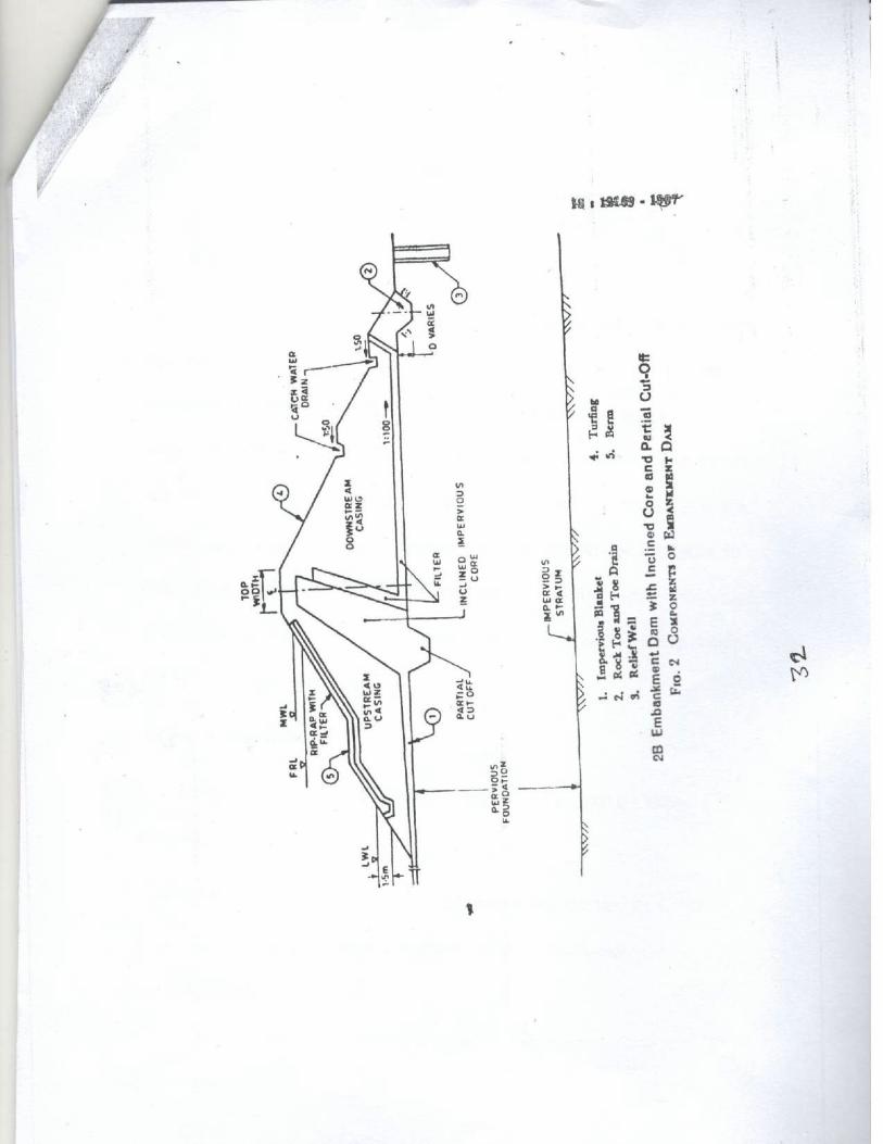
core of the dam as shown in Fig. 2B.
IS CODE 12169-1987 (REAFFIRMED 2003)
Para 4.7.1
The horizontal upstream impervious blanket is
provided to increase the path of seapage when
full cut-off is not practicable on pervious
foundations. The impervious blanket may be
provided either with or without partial cut-off.
Impervious blanket shall be connected to core
of the dam as shown in Fig. 2B.

5.12.2 The material to be used for impervious
blanket shall have the properties according to
IS:1498-1970. Appendix A gives
recommendations based on IS:1498-1970. A
300 mm thick layer of random material over the
blanket is recommended to prevent cracking due
to exposure to impervious blanket.
IS CODE 12169-1987 (REAFFIRMED 2003)
Para 4.7.2
The material to be used for impervious blanket
shall have the properties according to IS:1498-
1970. Appendix A gives recommendations
based on IS:1498-1970. A 300 mm thick layer
of random material over the blanket is
recommended to prevent cracking due to
exposure to atmosphere
5.12.3 The impervious blanket may be designed
in accordance with IS:8414-1977. As a general
guideline, impervious blanket with a minimum
thickness of 1.0 m and a minimum length of 5
times the maximum water head measured from
upstream toe of the core may be provided.
IS CODE 12169-1987 (REAFFIRMED 2003)
Para 4.7.3
The impervious blanket may be designed in
accordance with IS:8414-1977. As a general
guideline, impervious blanket with a minimum
thickness of 1.0 m and a minimum length of 5
times the maximum water head measured
from upstream toe of the core may be
provided.6 BASIC AND SPECIAL DESIGN REQUIREMENT 6 BASIC AND SPECIAL DESIGN
REQUIREMENT
6.1 The basic and special design requirements for
the design of embankment dams are to ensure -
6.1 The basic and special design requirements
for the design of embankment dams are to
ensure —
a) Safety against over-topping; a) Safety against over-topping;a) Safety against over-topping; a) Safety against over-topping;
b) Stability of slopes; b) Stability of slopes;
c) Safety against internal erosion; and c) Safety against internal erosion; and
d) Control of cracking. d) Control of cracking.
6.1.1 Over-topping 6.1.1 Over-topping
Sufficient spillway capacity and free board should
be provided to prevent over-topping of
embankment during and after construction. For
this, proper hydrological studies may be carried out.
The free board should be sufficient to prevent over-
topping by waves and should take into account the
settlement of embankment and its foundation.
Freeboard shall be provided as per T.C. No.22 -
Freeboard requirement in embankment dams
issued by BODHI.
Sufficient spillway capacity and free board should
be provided to prevent over-topping of
embankment during and after construction. For
this, proper hydrological studies may be carried
out. The free board should be sufficient to
prevent over-topping by waves and should take
into account the settlement of embankment and
its foundation. Freeboard shall be provided as
per T.C. No.22 -Freeboard requirement in
embankment dams issued by BODHI. Free
board for wave run up on slope shall be provided
in accordance with IS 10635-1983.
6.1.2 Stability Analysis 6.1.2 Stability Analysis
6.1.2.1 Necessity 6.1.2.1 Necessity

Stability analysis may not be necessary for
small dam's upto 10m. height provided a good
foundation is available at dam site. Stable
slopes can be decided on the basis of
experience.
The slopes of the embankment shall be stable
under all loading conditions. They should also be
flat enough so as not to impose excessive
stresses on foundation.
IS 12169-1987 (REAFFIRMED 2003) Para
5.1.2.1
The slopes of the embankment shall be stable
under all loading conditions. They should also
be flat enough so as not to impose excessive
stresses on foundation.
For small dams up to 10m-height, section may
be decided as per general guidelines for the
section and the recommended slopes as given
in Annexure-11.2 Embankment where height is
above 10m and up to 15m, stability analysis
may be carried out in accordance with the IS:
7894-1975 — Code of practice for stability
analysis of earth dams.
Stability analysis may not be necessary for small
dams up to 10 m height provided a good
foundation is available at dam site. Stable slopes
can be decided on the basis of experience.
However, where weak foundation conditions viz.
fissured clay, expensive soils, shales, over
consolidated highly plastic clays, soft clays
dispersive soils, etc, are met within the
substratum in the dam-seat, extensive
investigations of the foundation soil and borrow
area soil are required to be carried out and the
design of the embankment dam carried out in
accordance with IS : 7894-1975
IS 12169-1987 (REAFFIRMED 2003) Para
5.1.2.2
However, where weak foundation conditions
viz. fissured clay, expensive soils, shales, over
consolidated highly plastic clays, soft clays
dispersive soils, etc, are met within the
substratum in the dam-seat, extensive
investigations of the foundation soil and
borrow area soil are required to be carried out
and the design of the embankment dam
carried out in accordance with IS : 7894-1975
For small dams up to 10m-height, section may
be decided as per general guidelines for the
section and the recommended slopes as given in
Annexure-2. Embankment where height is above
10 m and up to 15m, stability analysis may be 10 m and up to 15m, stability analysis may be
carried out in accordance with the IS: 7894-1975
— Code of practice for stability analysis of earth
dams.6.1.3 Cracking 6.1.3 Cracking
Cracking of impervious zone may be one of the root
causes of failure of embankment dam; leading to
erosion, piping, breaching etc. Cracks are mostly
due to differential settlement in embankment
earthwork on account of abrupt changes in
foundation grade .The other causes of crack could
be poor quality control during construction, use of
faulty construction materials and earthquakes etc.
Cracking of impervious zone may be one of the
root causes of failure of embankment dam;
leading to erosion, piping, breaching etc. Cracks
are mostly due to differential settlement in
embankment earthwork on account of abrupt
changes in foundation grade .The other causes
of crack could be poor quality control during
construction, use of faulty construction materials
and earthquakes etc.
6.1.3.1 Preventive Measures 6.1.3.1 Preventive Measures
The following measures if adopted during
construction, will help to check the occurrence of
cracks in embankment:
The following measures if adopted during
construction, will help to check the occurrence of
cracks in embankment:

i) For the hearting or core, soils having values of
P.I.>15 should be used. Soil should be compacted
at OMC or slightly more than OMC.
i) For the hearting or core, soils having values of
P.I. (Plasticity Index) >15 should be used. Soil
should be compacted at OMC or slightly more
than OMC. In case of less plastic clay, 2 to 5
percent bentonite of 200 to 300 liquid limit may
be mixed to increase the plasticity.
IS 12169-1987 (REAFFIRMED 2003) Para
6.1.1 a)
In case of less plastic clay, 2 to 5 percent
bentonite of 200 to 300 liquid limit may be
mixed to increase the plasticity.
ii) Well graded filter should be provided in the
downstream side of the core (chimney filter) so that
even if cracking occurs, harmful effects will be
prevented;
ii) Well graded filter should be provided in the
downstream side of the core (chimney filter) so
that even if cracking occurs, harmful effects will
be prevented;
iii) Low density deposits in foundation may be
removed, if it is economically viable or other
alternative site/design be followed
iii) Low density deposits in foundation may be
removed, if it is economically viable or other
alternative site/design be followed
iv) Any vertical steps or ledge rock in the abutment
should be 'avoided. Steep slope of abutment
should be dressed to about 1(H): 2(V).
iv) Any vertical steps or ledge rock in the
abutment should be 'avoided. Steep slope of
abutment should be dressed to about 1(H): 2(V).
v) The size of hearting core should be increased to
reduce the possibility of transverse or horizontal
cracks extending through it.
v) The size of hearting core should be increased
to reduce the possibility of transverse or
horizontal cracks extending through it.
vi) Careful selection of fill materials to reduce
the differential movement. To restrict the rockfill
in lightly loaded outer casings and to use well
IS CODE 12169-1987 (REAFFIRMED 2003)
Para 6.1.1 c)
Careful selection of fill materials to reduce the in lightly loaded outer casings and to use well
graded materials in the inner casings on either
side of the core.
Careful selection of fill materials to reduce the
differential movement. To restrict the rockfill in
lightly loaded outer casings and to use well
graded materials in the inner casings on either
side of the core.vii) Wide transition zones of properly graded
filters of adequate width for handling drainage, if
cracks develop.
IS CODE 12169-1987 (REAFFIRMED 2003)
Para 6.1.1 d)
Wide transition zones of properly graded filters
of adequate width for handling drainage, if
cracks develop.
viii) Special treatment. such as preloading,
pre saturation, removal of weak material, etc, to
the foundation and abutment if warranted.
IS CODE 12169-1987 (REAFFIRMED 2003)
Para 6.1.1 e)
Special treatment. such as preloading, pre
saturation, removal of weak material, etc, to
the foundation and abutment if warranted.
ix) Delaying placement of core material in the
crack region till most of the settlement takes
place.
IS CODE 12169-1987 (REAFFIRMED 2003)
Para 6.1.1 f)
Delaying placement of core material in the
crack region till most of the settlement takes
place.

x) Arching the dam horizontally between steep
abutments.
IS CODE 12169-1987 (REAFFIRMED 2003)
Para 6.1.1 g)
Arching the dam horizontally between steep
abutments.
xi) Flattening the downstream slopes to
increase slope stability in the event of saturation
from crack leakage.
IS CODE 12169-1987 (REAFFIRMED 2003)
Para 6.1.1 h)
Flattening the downstream slopes to increase
slope stability in the event of saturation from
crack leakage.
xii) Cutting back the steep abutment slopes. IS CODE 12169-1987 (REAFFIRMED 2003)
Para 6.1.1 j)
Cutting back the steep abutment slopes.
6.1.4 Stability At Junctions 6.1.4 Stability At Junctions
Junctions of embankment dam with foundation
abutments, masonry structure like over-flow and
non-overflow dams and outlets need special
attention with reference to following criteria:
Junctions of embankment dam with foundation
abutments, masonry structure like over-flow and
non-overflow dams and outlets need special
attention with reference to following criteria:
a) Good bond between embankment dam and
foundation;
a) Good bond between embankment dam and
foundation;
b) Adequate creep length at junction. b) Adequate creep length at junction.
c) Protection of embankment dam slope against
scouring action; and
c) Protection of embankment dam slope against
scouring action; and
d) Easy movement of traffic. d) Easy movement of traffic.
6 .1.4.1 Junction With Foundation 6 .1.4.1 Junction With Foundation6 .1.4.1 Junction With Foundation 6 .1.4.1 Junction With Foundation

Embankment dam may be founded on soil over
burden or rock. For foundation on soils or non-
rocky strata, vegetation like bushes, grass roots,
trees etc., should be completely removed. After
removal of these materials, the foundation surface
should be moistened to the required extent and
adequately rolled before placing embankment
material. For rocky foundation surface should be
cleaned off all loose fragments including semi-
detached and over hanging surface blocks of rocks.
Proper bond should be established between the
embankment and the rock surface of the
foundation. For achieving this, a 10cm thick layer of
cohesive soil in muddy form be pasted on the clean
rocky foundation and rolled. This treatment after
drying leaves a base for earthwork. Due to rolling,
the mud also fills up the cracks and joints of
foundation up to some extent.
Embankment dam may be founded on soil over
burden or rock. For foundation on soils or non-
rocky strata, vegetation like bushes, grass roots,
trees etc., should be completely removed. After
removal of these materials, the foundation
surface should be moistened to the required
extent and adequately rolled before placing
embankment material. For rocky foundation
surface should be cleaned off all loose fragments
including semi-detached and over hanging
surface blocks of rocks. Proper bond should be
established between the embankment and the
rock surface of the foundation. For achieving
this, a 10cm thick layer of cohesive soil in muddy
form be pasted on the clean rocky foundation
and rolled. This treatment after drying leaves a
base for earthwork. Due to rolling, the mud also
fills up the cracks and joints of foundation up to
some extent.
6.1.4.2 Junction With Abutment 6.1.4.2 Junction With Abutment
In order to get good contact between the
impervious core of the embankment and the rock
overhanging, the rocky abutment should be suitably
shaped and prepared. Vertical surface should be
In order to get good contact between the
impervious core of the embankment and the rock
overhanging, the rocky abutment should be
suitably shaped and prepared. Vertical surface shaped and prepared. Vertical surface should be
excavated to form slopes, not steeper than 0.25(H)
to 1(V). A wider impervious zone and thicker
transition should be provided, at the abutment
contact to increase the length of path of seepage
and to protect against erosion. In addition to para
6.1.4.1, sufficient creep length should be provided
between impervious section of the dam and the
abutment so as to provide safety against piping_
The creep length should be not less than four times
the hydraulic head.
suitably shaped and prepared. Vertical surface
should be excavated to form slopes, not steeper
than 0.25(H) to 1(V). A wider impervious zone
and thicker transition should be provided, at the
abutment contact to increase the length of path
of seepage and to protect against erosion. In
addition to para 6.1.4.1, sufficient creep length
should be provided between impervious section
of the dam and the abutment so as to provide
safety against piping. The creep length should be
not less than four times the hydraulic head.
6.1.4.3 Junction With Non-Overflow Dam 6.1.4.3 Junction with Non-Overflow Dam

Junction of non-overflow masonry or concrete dam
with embankment dam is provided by a batter not
steeper than 1(H) to 2(V) to the end face of the non-
overflow section block coming in contact with the
impervious core. A wider impervious zone, a thicker
transition shall be provided at the abutment
contacts to increase the length of path of seepage
and to protect against erosion. Sometimes, the
junction of earth dam with non-overflow dam is
provided with earth retaining walls perpendicular or
skew at the junction of non-overflow dam.
Junction of non-overflow masonry or concrete
dam with embankment dam is provided by a
better not steeper than 1(H) to 2(V) to the end
face of the non-overflow section block coming in
contact with the impervious core. A wider
impervious zone, a thicker transition shall be
provided at the abutment contacts to increase
the length of path of seepage and to protect
against erosion. Sometimes, the junction of earth
dam with non-overflow dam is provided with
earth retaining walls perpendicular or skew at the
junction of non-overflow dam.
7.0 This circular supersedes T.C.No.401W (M) 63
dated 18-5-63 — Type profile of earth dams.
7.0 This circular supersedes
T.C.No.42/BODHI/R&C/TC date 17.01.2001.
List of Indian Standards List of Indian Standards
IS 12169-1987 : Design of small embankment
dams
IS 12169-1987 : Design of small embankment
dams
IS 8826-1976 :Guide lines for design of large earth
and rock fill dams.
IS 8826-1976 :Guide lines for design of large
earth and rock fill dams.
IS 7894-1975 :Code of practice for stability analysis
of earth dams.
IS 7894-1975 :Code of practice for stability
analysis of earth dams.
IS 8237-1985 :Code of practice for protection of
slope for reservoir embankment
IS 8237-1985 :Code of practice for protection of
slope for reservoir embankmentslope for reservoir embankment slope for reservoir embankment
IS 8414-1977 :Guidelines for design of under
seepage control measures for earth and rockfill
dams.
IS 8414-1977 :Guidelines for design of under
seepage control measures for earth and rockfill
dams.
IS 9429-1980 : Code of practice for drainage
system for earth and rockfill dams.
IS 9429-1980 : Code of practice for drainage
system for earth and rockfill dams.
1S 10635-1993 : Free board requirement in
embankment dams-guidelines.
1S 10635-1993 : Free board requirement in
embankment dams-guidelines.
IS 1498-1970 : Classification and identification of
soils for general engineering purposes.
IS 1498-1970 : Classification and identification of
soils for general engineering purposes.


![contenthub.bvsd.org Catalog/5 6... · Web viewDRAFT. DRAFT. DRAFT. DRAFT. DRAFT. DRAFT. DRAFT. DRAFT. DRAFT. DRAFT. DRAFT. DRAFT. 6/15/2016BVSD Curriculum Essentials44 [Course Name]](https://img.pdfslide.us/doc/110x75/5d46356d88c99379458b9579/catalog5-6-web-viewdraft-draft-draft-draft-draft-draft-draft-draft.jpg)

![contenthub.bvsd.org Course... · Web viewDRAFT. DRAFT. DRAFT. DRAFT. DRAFT. DRAFT. DRAFT. DRAFT. DRAFT. DRAFT. DRAFT. DRAFT. 12/28/2015BVSD Curriculum Essentials32 [Course Name]](https://img.pdfslide.us/doc/110x75/5e38c5b23f41ba01b81b757e/course-web-view-draft-draft-draft-draft-draft-draft-draft-draft-draft.jpg)


![contenthub.bvsd.org Course... · Web viewDRAFT. DRAFT. DRAFT. DRAFT. DRAFT. DRAFT. DRAFT. DRAFT. DRAFT. DRAFT. DRAFT. DRAFT. 6/15/2016BVSD Curriculum Essentials44 [Course Name] Curriculum](https://img.pdfslide.us/doc/110x75/5a9eefd17f8b9a67178c19c5/doc-courseweb-viewdraft-draft-draft-draft-draft-draft-draft-draft-draft.jpg)