Embed Size (px)
Citation preview

Before theFEDERAL COMMUNICATIONS COMMISSION
Washington, DC 20554
In the Matter of
Establishment of an Interference Temperature Metric to Quantify and Manage Interference and to Expand Available Unlicensed Operation in Certain Fixed, Mobile and Satellite Frequency Bands
)))))))
ET Docket No. 03-237
COMMENTS OF THE NATIONAL TELECOMMUNICATIONSAND INFORMATION ADMINISTRATION
Michael D. Gallagher Kathy D. SmithAssistant Secretary for Chief CounselCommunications and Information
Fredrick R. WentlandAssociate AdministratorOffice of Spectrum Management
Mark SettleEdward DrocellaElectronics Engineers
Office of Spectrum Management National Telecommunications andInformation AdministrationU.S. Department of CommerceRoom 47131401 Constitution Avenue, N.W.Washington, DC 20230(202) 482-1816
August 13, 2004
TABLE OF CONTENTS
Section Page
EXECUTIVE SUMMARY.......................................................................................................v
I. INTRODUCTION.........................................................................................................2
II. INTERFERENCE TEMPERATURE LIMITS COULD BE USED AS A MEASURE FOR DETERMINING APPROPRIATE DEVICE CHARACTERISTICS FOR OPPORTUNISTIC USE OF THE SPECTRUM, BUT SHOULD NOT BE CONSIDERED A BASIS FOR DETERMINING NON-INTERFERENCE FROM AN UNLICENSED DEVICE........................................................................................5
III. THE INTERFERENCE TEMPERATURE MODEL SHOULD NOT BE USED TO FACILITATE UNDERLAYING UNLICENSED DEVICE OPERATIONS IN FREQUENCY BANDS LISTED IN SECTION 15.205 OF THE COMMISSION’S RULES...........................................................................................................................6
IV. THE FREQUENCY BANDS TRANSFERRED FROM THE FEDERAL GOVERNMENT SHOULD BE CONSIDERED FOR THE INITIAL IMPLEMENTATION OF THE INTERFERENCE TEMPERATURE MODEL.......11
V. HIGHER-POWERED UNLICENSED DEVICES EMPLOYING DYNAMIC FREQUENCY SELECTION MAY BE DIFFICULT TO IMPLEMENT IN THE FIXED SERVICE FREQUENCY BANDS, HOWEVER, EMPLOYING GEO-LOCATION TECHNOLOGY MAY PERMIT SHARING OPPORTUNITIES........14
VI. OPERATIONAL PARAMETERS THAT ARE UNIQUE TO INDIVIDUAL RADIO SERVICES MUST BE CONSIDERED IN DEVELOPING INTERFERENCE TEMPERATURE LIMITS..........................................................................................17
VII. A THRESHOLD BASED ON A ΔT/T OF ONE PERCENT SHOULD BE EMPLOYED FOR SITUATIONS WHERE UNLICENSED DEVICES ARE SHARING WITH FIXED-SATELLITE SERVICE UPLINK RECEIVERS.............20
VIII. GEO-LOCATION TECHNOLOGY CAN BE USED TO FACILITATE SHARING BETWEEN UNLICENSED DEVICES AND RADIO ASTRONOMY OPERATIONS IN THE 6650-6675.2 MHz FREQUENCY BAND...........................24
ii

IX. GEO-LOCATION TECHNOLOGY CAN BE USED TO PREVENT UNCOORDINATED USE OF SPECTRUM WITHIN RADIO QUIET ZONES, AND COORDINATION ZONES...............................................................................26
X. THE PARAMETERS OF THE REFERENCE RECEIVER USED TO ESTABLISH THE INTERFERENCE TEMPERATURE LIMITS COULD BE DEVELOPED IN THE COMMISSION’S RULEMAKING PROCEEDING ON RECEIVER STANDARDS.............................................................................................................30
XI. SPATIAL, ANGULAR, TEMPORAL, AND FREQUENCY FACTORS MUST BE CONSIDERED IN ACCURATELY MEASURING THE INTERFERENCE TEMPERATURE LIMITS..........................................................................................33
XII. DOMESTICALLY AND INTERNATIONALLY DEVELOPED STANDARDS COULD BE USED FOR DEFINING THE PERMISSIBLE INTERFERENCE LEVELS FOR EACH RADIO SERVICE..................................................................38
XIII. DEFINING INTERFERENCE TEMPERATURE IN TERMS OF SIGNAL-TO-NOISE RATIO COULD PROVIDE GREATER FLEXIBILITY AND CERTAINTY THAT BOTH INCUMBENT AND FUTURE SPECTRUM USERS DESIRE.........42
XIV. IN ORDER TO MAXIMIZE THE USEFULNESS OF MEASURED INTERFERENCE TEMPERATURE LEVELS, THE PARAMETERS OF THE MEASUREMENT SYSTEM SHOULD BE STANDARDIZED...............................44
XV. BEFORE IMPLEMENTING THE INTERFERENCE TEMPERATURE MODEL, THE RIGHTS AND RESPONSIBILITIES OF BOTH LICENSED AND UNLICENSED SPECTRUM USERS MUST BE DEFINED....................................47
XVI. TO EFFECTIVELY IMPLEMENT THE INTERFERENCE TEMPERATURE MODEL, REPRESENTATIVE OPERATIONAL SCENARIOS MUST BE DEVELOPED FOR EACH RADIO SERVICE..........................................................49
XVII. THE INTERFERENCE TEMPERATURE LIMITS MUST PROTECT BOTH IN-BAND AND ADJACENT BAND SPECTRUM USERS...........................................53
XVIII. ADDITIONAL PROVISIONS ARE NOT NECESSARY TO PROTECT DEEP SPACE NETWORK RECEIVERS IN THE 12.75-13.25 GHz BAND LOCATED AT THE GOLDSTONE COMPLEX................................................................................55
iii

XIX. TECHNICAL ISSUES RELATED TO THE COMPLIANCE MEASUREMENTS OF UNLICENSED DEVICES THAT EMPLOY THE INTERFERENCE TEMPERATURE MODEL MUST BE ADDRESSED..............................................56
XX. THE INTERFERENCE TEMPERATURE LIMITS IN A FREQUENCY BAND SHOULD BE BASED ON THE MOST SENSITIVE RADIO SERVICE OPERATING IN A BAND.........................................................................................59
XXI. INTERFERENCE TEMPERATURE MEASUREMENTS MADE BY A SATELLITE RECEIVER CANNOT BE USED TO PROTECT GROUND-BASED RECEIVERS................................................................................................................60
XXII. BASELINE MEASUREMENTS IN SELECTED LICENSED AND UNLICENSED FREQUENCY BANDS SHOULD BE PERFORMED BEFORE DECIDING WHETHER OR NOT THE INTERFERENCE TEMPERATURE MODEL CAN BE IMPLEMENTED.........................................................................................................63
XXIII. CONCLUSION............................................................................................................65
ASSESSMENT OF PROPOSED POWER LEVEL AND DETECTION THRESHOLD IN THE 6 GHz AND 13 GHz FIXED SERVICE FREQUENCY BANDS…………………………………………………………………APPENDIX A
ASSESSMENT OF POTENTIAL INTERFERENCE TO GOLDSTONE DEEP SPACE NETWORK OPERATIONS IN THE 12.75-13.25 GHz BAND…...……………………………………………………………..APPENDIX B
DISCUSSION OF THE CRITICAL PARAMETERS OF THE INTERFERENCE TEMPERATURE MEASUREMENT SYSTEM ………………………APPENDIX C
DISCUSSION OF OPPORTUNITIES THAT CAN EXIST FOR UNLICENSED DEVICE USE IN CERTAIN AREAS, WHILE PROTECTING THE LOCATIONS THAT ARE POTENTIALLY MORE SENSITIVE TO INTERFERENCE…...…………………………………………………APPENDIX D
ASSESSMENT OF THE POTENTIAL IMPACT OF INCREASING THE NOISE FLOOR…………………………………………………………APPENDIX E
iv

EXECUTIVE SUMMARY
The National Telecommunications and Information Administration (NTIA) commends
the Federal Communications Commission (Commission) for initiating this proceeding that will
examine a more quantitative approach to spectrum management with the goals of providing radio
service licensees with greater certainty regarding the maximum permissible interference present
in the frequency bands in which they operate and possibly allowing more opportunistic access to
the spectrum by unlicensed devices. NTIA believes that properly developed quantitative
permissible interference standards could assist the Commission in assessing the degree of
potential harm from interference caused by undesired signals. NTIA believes that the
interference temperature metric, which quantifies the levels of interference at the licensed user’s
receiver, should be examined to assess whether it can be used to allow greater access to the radio
frequency spectrum. However, NTIA believes that opportunistic use of frequency bands by
means of the interference temperature limit is not appropriate for all frequency bands. NTIA
offers the following comments in response to the specific issues raised in the Commission’s
Notice of Inquiry and Notice of Proposed Rulemaking (NOI/NPRM) on the establishment of the
interference temperature metric.
NTIA recommends the following:
Any device authorized to make opportunistic use of spectrum within the
interference temperature limits must still be subject to the general conditions of
unlicensed device operation.
Unlicensed devices using the interference temperature model should not be
employed in the frequency bands listed in Section 15.205 of the Commission’s
Rules.v
Initially, the Commission should consider implementing the interference
temperature model in the frequency bands that have been transferred from federal
government to private sector use in accordance with the requirements of Title VI
of the Omnibus Budget Reconciliation Act of 1993 and the Balanced Budget Act
of 1997.
The Commission should not adopt the power levels and dynamic frequency
selection (DFS) detection thresholds developed for sharing with radar systems
without performing a further analysis that takes into account specific technical
factors unique to fixed service (FS) systems.
Geo-location technology that unlicensed devices can employ to facilitate sharing
with the FS can also be employed to protect the radio astronomy observatories
monitoring the methanol spectral line in the 6650-6675.2 MHz band.
The Commission should not adopt interference temperature limits without
performing the appropriate supporting technical studies.
A change in the receiver temperature divided by the receiver temperature (ΔT/T)
threshold of 1 percent is appropriate for sharing between unlicensed devices and
fixed-satellite service uplink receivers.
The Commission should issue a follow-on NPRM that builds upon the existing
public record established in the NOI on receiver performance requirements to
determine the reference receiver performance parameters to be used in
establishing interference temperature limits.
The results of the first phase of NTIA’s study on interference protection criteria
values for specific radio services be included as part of an NOI to establish
vi

maximum permissible interference levels applicable to the various radio services.
The parameters of the interference temperature measurement system should be
identified for each frequency band and standardized to maximize the usefulness of
the measurements.
Before the interference temperature model is implemented, the rights and
responsibilities of spectrum users should be addressed.
Operational scenarios and maximum permissible interference limits should be
developed for each radio service to be used in determining the interference
temperature limits.
When establishing the interference temperature limits, the emissions from
licensed and unlicensed systems operating in adjacent or harmonically related
frequency bands should be taken into consideration.
Prior to implementing the interference temperature model, technical issues related
to performing the compliance measurements should be resolved.
The interference temperature limit for unlicensed devices should be established to
protect both primary and secondary allocated services within the frequency band.
The Commission should not use the ΔT/T levels measured by a satellite receiver
to control the operating characteristics of unlicensed devices.
NTIA and the Commission should identify a list of candidate licensed and
unlicensed frequency bands where the emission or noise levels can be measured
using standardized measurement systems, and these measurements should serve
as a baseline for characterizing the existing emission environment in those bands.
vii

NTIA commends the Commission for initiating this proceeding examining possibilities to
expand the options for unlicensed device use while providing certainty and predictability desired
by licensed spectrum users. NTIA agrees with the Commission regarding the benefits that could
be gained by increasing spectrum access opportunities for unlicensed devices. Implementation
of the interference temperature model and the use of interference mitigation techniques such as
DFS and geo-location represent a shift in interference management from the transmitter to the
receiver. The NOI identifies many technically challenging issues that must be addressed before
the interference temperature model can be implemented in a frequency band. These technical
issues, include but are not limited to: development of radio service specific reference receiver
parameters; development of radio service specific maximum permissible interference limits and
operational scenarios; and measurement of the existing radio frequency signal environment in
order to establish a proper baseline. Until these technical issues, as well as the rights and
responsibilities of spectrum users have been resolved, wide-spread implementation of the
interference temperature model will not possible. Because of the sensitive nature of the
operations in many of the restricted frequency bands, implementing the interference temperature
model would be difficult, if not impossible. However, if the initial implementation of the
interference temperature model were limited to specific bands, for example, bands transferred
from the federal government, many of the technical issues listed above could be addressed and
possibly resolved with minimal impact to incumbent spectrum users. NTIA believes interference
mitigation techniques, such as DFS and geo-location, hold great promise for facilitating sharing
between licensed and unlicensed spectrum users. However, these techniques should not be
employed until the supporting studies examining the specific characteristics of the licensed
services and unlicensed device applications have been completed.
viii

Before theFEDERAL COMMUNICATIONS COMMISSION
Washington, DC 20554
In the Matter of
Establishment of an Interference Temperature Metric to Quantify and Manage Interference and to Expand Available Unlicensed Operation in Certain Fixed, Mobile and satellite Frequency Bands
)))))))
ET Docket No. 03-237
COMMENTS OF THE NATIONAL TELECOMMUNICATIONSAND INFORMATION ADMINISTRATION
The National Telecommunications and Information Administration (NTIA), an Executive
Branch agency within the Department of Commerce, is the President’s principal adviser on
domestic and international telecommunications policy, including policies relating to the Nation’s
economic and technological advancement in telecommunications. Accordingly, NTIA makes
recommendations regarding telecommunications policies and presents Executive Branch views
on telecommunications matters to the Congress, the Federal Communications Commission
(Commission), and the public. NTIA, through the Office of Spectrum Management (OSM), is
also responsible for managing the federal government’s use of the radio frequency spectrum.
NTIA respectfully submits the following comments in response to the Commission’s Notice of
Inquiry and Notice of Proposed Rulemaking (NOI/NPRM) in the above-captioned proceeding.1
1. Establishment of an Interference Temperature Metric to Quantify and Manage Interference and to Expand Available Unlicensed Operation in Certain Fixed, Mobile and Satellite Frequency Bands, Notice of Inquiry and Notice of Proposed Rulemaking, ET Docket No. 03-237, 18 F.C.C. Rcd. 25309 (2003) (“NOI/NPRM”).

I. INTRODUCTION
In this NOI/NPRM the Commission seeks comments on a new interference temperature
metric for quantifying and managing interference. The Commission believes that this metric
could shift the current method for assessing interference, which is based on the emissions
generated by the transmitter, to an approach that is based on the actual radio frequency (RF)
environment, taking into account the interactions between transmitters and receivers. As
envisioned, the Commission believes that the interference temperature metric could allow non-
licensed device operations within licensed frequency bands based on the unlicensed user(s) not
exceeding the interference temperature limit.
The Commission, in the NOI portion of this proceeding, requests comment on a number
of issues relating to the development and use of the interference temperature metric for managing
a possible transition from the current transmitter-based approach for interference management to
the new interference temperature metric. The Commission poses questions concerning the
development of the interference temperature metric, including the determination of interference
temperature limits for specific frequency bands, and an assessment of the cumulative noise and
interference environment in RF bands, including standard methodologies for making assessments
to support the selection of those limits. In the NPRM portion of this proceeding, the
Commission seeks comment on technical rules that would permit higher-powered unlicensed
device operation in specific frequency bands used primarily by fixed-satellite uplinks and
terrestrial fixed point-to-point links.
The interference temperature metric in and of itself is not a new concept, and has been
used extensively in the satellite and radio astronomy services, where the distances from the
2

receiver to RF sources are very large.1 For example in the fixed-satellite service a change in
receiver temperature divided by receiver temperature (ΔT/T) criterion has been used by the
International Telecommunication Union (ITU) as a trigger for coordination of co-primary
satellite systems. However, the Commission’s proposals to establish and codify interference
temperature limits: based on actual measurements of the RF environment and using the RF
environment measurements to permit underlaying higher-powered unlicensed devices in bands
used by licensed radio services are new concepts that must be evaluated very carefully.
There are several ongoing Federal programs that could benefit from establishing
interference temperature limits in some frequency bands. The Department of Defense (DoD) is
developing the neXt Generation (XG) program through the Defense Advanced Research Projects
Agency (DARPA).2 Like DARPA’s early work on the Internet, XG-based technology is
applicable to both military and civilian applications. The National Science Foundation (NSF) is
also exploring the technology developments needed for enhancing spectral efficiencies of
wireless networks in support of expanding opportunities for new services in the wireless
industry. NSF’s Networking Technology Systems (NeTS) program is addressing the challenges
associated with these networks.3
NTIA agrees with recommendations made in the Spectrum Policy Task Force (SPTF)
Report that the Commission should explore adopting a more quantitative approach to spectrum
1. The distance between the source in the sky and the receiving antenna on the surface of the earth varies little, and a single temperature can be used to adequately describe the amount of energy coming from the source.
2. XG Working Group, The XG Vision, Request for Comments Version 2.0, BBN Technologies, Cambridge, Massachusetts. This document and other information about the DARPA XG program are available at http://www.darpa.mil/ato/programs/XG/rfcs.htm.
3. National Science Foundation, Directorate for Computer and Information Science Engineering, Division of Computer and Network Systems, Research in Networking Technology and Systems (NeTS). More information on the NeTS program is available at http://www.cise.nsf.
3

(interference) management.4 Many of the issues raised in the SPTF report were also addressed in
NTIA’s Spectrum Summit.5 NTIA believes that properly developed quantitative permissible
interference standards could assist the Commission in assessing the degree of potential harm
from interference caused by undesired signals. NTIA understands that the interference
temperature metric as proposed is to quantify and manage the permissible levels of interference
at the licensed user’s receivers. NTIA believes that the interference temperature metric should
be examined to assess whether it can be used to allow greater access to the RF spectrum.
However, opportunistic use of frequency bands by means of an interference temperature metric
is not appropriate for all frequency bands. NTIA also believes that the determination of the level
of interference that a non-licensed user can or will cause is difficult to ascertain. This level of
interference is a function of many factors that include, but are not limited to, the transmit power
of the non-licensed user, the propagation loss between the non-licensed and licensed users, the
antenna pattern and gain of the licensed and non-licensed users, and possibly the aggregation of
interference resulting from multiple users (non-licensed and licensed).
NTIA supports the Commission in its investigation of the interference temperature metric
to quantify and manage interference in a more precise fashion and to expand the opportunities
for new services in the wireless industry, while at the same time to provide licensed operations
with greater certainty regarding the maximum permissible interference level and greater
protection against interference. NTIA offers the following comments in response to the specific
issues raised in the Commission’s NOI/NPRM.
4. Federal Communications Commission, Spectrum Policy Task Force Report, ET Docket No. 02-135, at 5 (November 15, 2002) (“SPTF Report”).
5. NTIA hosted a summit on April 4-5, 2002, to help identify the best solutions to challenges posed by management of the nation’s airwaves.
4

II. INTERFERENCE TEMPERATURE LIMITS COULD BE USED AS A MEASURE FOR DETERMINING APPROPRIATE DEVICE CHARACTERISTICS FOR OPPORTUNISTIC USE OF THE SPECTRUM, BUT SHOULD NOT BE CONSIDERED A BASIS FOR DETERMINING NON-INTERFERENCE FROM AN UNLICENSED DEVICE.
In the NOI, the Commission seeks comment on the feasibility of using interference
temperature as a general approach to spectrum management. The Commission specifically seeks
comment on whether a general metric can be used to gauge the success of the introduction of the
interference temperature into a new frequency band. Comments are also sought on whether there
is a simple metric that can be used to gauge the effect of these unlicensed devices upon the
incumbent services.1
The interference temperature model has merit as a measure of received undesired energy,
and potentially as a means to determine how a device should or should not operate in order to
minimize the potential for interference. However, any device authorized to make opportunistic
use of spectrum within the interference temperature limits must still be subject to the general
conditions of unlicensed operation. Specifically, persons operating intentional or unintentional
radiators shall not be deemed to have any vested right to continued use of any given frequency
by virtue of prior registration or certification of equipment, and also these devices may not cause
harmful interference, and must accept interference from authorized users of the spectrum.2 No
“safe harbor” approach should be utilized, since an objective of this proceeding is to provide
radio service licensees with greater certainty regarding the maximum permissible interference,
and greater protections against harmful interference that could be present in the frequency bands
in which they operate.3 Additionally, the interference temperature model should not impact the
1. NOI/NPRM at ¶ 21.
2. See 47 C.F.R. § 15.5.
3. NOI/NPRM at ¶ 1.5

definition of harmful interference, which is defined as “[i]nterference which endangers the
functioning of a radionavigation service or of other safety services or seriously degrades,
obstructs, or repeatedly interrupts a radiocommunication service operating in accordance with
these [International] Radio Regulations.”4
III.THE INTERFERENCE TEMPERATURE MODEL SHOULD NOT BE USED TO FACILITATE UNDERLAYING UNLICENSED DEVICE OPERATIONS IN FREQUENCY BANDS LISTED IN SECTION 15.205 OF THE COMMISSION’S RULES.
In the NOI, the Commission acknowledges that licensees would prefer to see the
interference temperature limits in the bands they use set low, while the manufacturers and users
of unlicensed devices would prefer to see these limits set high. The Commission requests
comment on whether there are some services or frequency bands for which the Commission
should continue to use the current interference protection procedures.1
Unlicensed devices that would operate under the Commission’s proposed interference
temperature model would still have to comply with the fundamental conditions of operating
under Part 15 of the Commission’s Rules. For example, unlicensed devices operating under the
interference temperature model would still be required to accept whatever interference is
received and must correct whatever interference is caused to licensed services, even if this means
ceasing operation.2 Also, unlicensed devices may not operate in the designated restricted
frequency bands listed in Section 15.205 of the Commission’s Rules.3 The restricted frequency
bands include bands used to support safety-of-life functions such as aeronautical radionavigation
4. See 47 C.F.R. § 2.1.
1. NOI/NPRM at ¶ 21. 2. See 47 C.F.R. § 15.5.3. See 47 C.F.R. § 15.205.
6

and bands employed by radio services that must function, as a nature of their operation, using
extremely low received signal levels. The systems that operate in these frequency bands may be
passive, such as radio astronomy, or active, such as satellite downlinks. In these restricted
frequency bands, only spurious and unintentional emissions are permitted. The only exception to
this prohibition is for devices employing ultrawideband (UWB) technology operating under
SubPart F of Part 15 of the Commission’s Rules. Unlicensed devices that employ UWB
technology, by their very nature, have wide transmit bandwidths and cannot avoid operation in
many of the restricted frequency bands. Operation in the restricted frequency bands has also
been permitted under specific circumstances.4
It is difficult to envision how the interference temperature model as described in the NOI
can be implemented to manage interference in the restricted frequency bands without
establishing interference temperature limits that are so low that any commercial wireless device
would be rendered useless. For example, it does not appear possible to allow opportunistic use
of radio astronomy bands and still protect radio astronomy observatories and other passive
sensing applications by employing the interference temperature model, due to the nature and
extremely low power of the cosmic signals the radio astronomers need to study. The permissible
interference levels for primary radio astronomy frequency bands are given in ITU-
Radiocommunications Sector (ITU-R) Recommendation RA.769.5 Table 1 gives the permissible
interference levels, and the corresponding interference temperature limits in several radio
astronomy frequency bands.
4. In the 608-614 MHz frequency band used by radio astronomers for Very Long Baseline Interferometry, the Wireless Medical Telemetry Service is permitted, but operation is limited to health care facilities and frequency coordination is necessary.
5. ITU-R Recommendation RA.769-1, Protection Criteria Used for Radioastronomical Measurements (1992-1995).
7

Table 1.
Frequency Range(MHz)
Permissible Interference Level(dB(W/m2Hz))
Interference Temperature(K)
608-614 -253 7 x 10⁻⁵
1400-1427 -255 8 x 10⁻⁶
4990-5000 -241 1.7 x 10⁻⁵
The interference temperature levels shown in Table 1 were calculated using the power
flux density for the maximum permissible interference level specified in ITU-R
Recommendation RA.769, assuming that the radio telescope receives interference through the
sidelobe of the antenna (assuming 0 dBi gain). A 2000 second integration time is used in the
calculation of the permissible interference levels in ITU-R Recommendation RA.769. If a longer
integration time is used, as frequently occurs in sensitive radio astronomy observations, the
tolerable interference temperature levels would be further reduced.
NTIA does not believe that wireless consumer devices, on a real-time basis, will be able
to measure such low levels of interference temperature, and such measurements are believed to
be outside of the range of any practical monitoring station. Therefore, it would not be practical
to monitor such low interference temperatures by any of the methods described in the NOI.6
Even if someday such monitoring capabilities were to become feasible, because of the low
interference temperature required to protect radio astronomy and passive operations, few if any
new opportunities could be expected to become available to other spectrum users.
Figure 1 of the NOI illustrates the interference temperature model by showing a “service
range” that decreases with distance from the transmitter.7 This may be applicable to
communication systems. However, there is no equivalent service range for radio astronomers
6. NOI/NPRM at ¶ 10.
7. NOI/NPRM at ¶ 15.
8

and the passive services. The power at the radio astronomy receiver is a line that is parallel to
the original noise floor shown in Figure 1 of the NOI, and in fact, may lie well below that noise
floor. Communication signals and those that radio astronomers and passive services seek to
detect are very different, providing another reason why the interference temperature model
should not be applied in the restricted frequency bands. For example, celestial signals are 1x10⁶
to 1012 times weaker than typical communication signals and consist of Gaussian noise with little
or no modulation.8 When observing a celestial source, radio astronomers detect small increases
in the noise power over the ambient noise at the output of the receiver by performing long
integrations (often lasting several hours and even days) by accurately pointing at and tracking the
celestial source. By a combination of increased integration time and increased bandwidth, noise
fluctuations at the celestial source are reduced by a large factor. By contrast, interfering signals
due to communication systems vary in time, either intrinsically, or because they are seen drifting
through the sidelobe structure of the telescope, as it tracks the celestial source being observed,
and these signals are not likely to average out with time.
In addition to the gains in scientific knowledge that results from radio astronomy and
passive sensing, related research spawns technological developments that are of direct and
tangible benefit to the public have emerged. For example, radio astronomy techniques have
8. A few sources such as pulsars, show rapid, periodic variations in time, others show slow variability on the scale of weeks or months.
9

contributed significantly to major advances in the following areas: computerized tomography as
well as other technologies for studying and creating images of tissue inside the human body;
increasing the ability to forecast earthquakes using very-long-baseline-interferometric (VLBI)
measurements of fault motion; and use of VLBI techniques in the development of wireless
telephone geographic location technologies that can be used in connection with the
Commission’s Enhanced-911 requirements.9 The continued development of new critical
technologies by passive scientific observers of the spectrum depends on researchers having
continued access to interference-free spectrum.
NTIA believes that there are several technical problems associated with employing the
interference temperature model in the restricted frequency bands, such as the limitations in the
monitoring systems and the limited commercial viability for unlicensed devices operating at the
permissible interference levels required in many of the restricted frequency bands. The
prohibition on unlicensed device operations in the restricted frequency bands is the only practical
method to protect sensitive operations that must measure extremely low signal levels. Therefore,
NTIA does not support employing the interference temperature model to allow unlicensed use in
the frequency bands listed in Section 15.205 of the Commission’s Rules. NTIA believes that this
should not impact the Commission’s ability to examine the feasibility of the interference
temperature model, since there is sufficient spectrum available outside of the restricted frequency
bands.
9. Reply Comments of Cornell University, ET Docket No. 02-135, at 4 (July 23, 2002).10

IV. THE FREQUENCY BANDS TRANSFERRED FROM THE FEDERAL GOVERNMENT SHOULD BE CONSIDERED FOR THE INITIAL IMPLEMENTATION OF THE INTERFERENCE TEMPERATURE MODEL. In the NOI, the Commission seeks comment on whether the introduction of devices
employing the interference temperature model should be done in stages to ensure that incumbent
radio services do not suffer undue interference. For example, the Commission asks how it
should limit the initial introduction of the devices to protect the incumbent systems if the
interference temperature were implemented in stages.1
Many of the parties that submitted comments in response to the Commission’s SPTF
Report believe that there are potential problems with the interference temperature model as
proposed in the report.2 These commenters represent a broad class of commercial terrestrial and
satellite service providers, equipment manufacturers, and industry associations. Several
commenters believe that the adoption of the interference temperature model, to allow the
underlaying of unlicensed devices, will degrade the performance of currently deployed systems
and may make future systems more costly, or inhibit the deployment of new technologies by
incumbent service providers.3 The incumbent service operators also believe that since the
1. NOI/NPRM at ¶ 20.
2. V-COMM L.L.C. Reply Comments, ET Docket No. 02-135, at 7 (February 28, 2003); Cellular Telecommunications and Internet Association Comments, ET Docket No. 02-135, at 10 (January 27, 2003); Cingular Comments, ET Docket No. 02-135, at 17 ( January 27, 2003 ) (“Cingular Comments”); AT&T Wireless Services, Inc. Comments, ET Docket No. 02-135, at 9 (January 27, 2003) (“AT&T Comments”); Telecommunications Industry Association Comments, ET Docket No. 02-135, at 8 (January 27, 2003); Lucent Technologies Inc. Comments, ET Docket No. 02-135, at 2 ( January 27, 2003 ); Motorola Comments, ET Docket No. 02-135, at 13 (January 27, 2003); United Telecom Council Comments, ET Docket No. 02-135, at 5 (January 27, 2003); The Boeing Company Comments, ET Docket No. 02-135, at 8 (January 27, 2003); Lockheed Martin Corporation Comments, ET Docket No. 02-135, at 6 (January 27, 2003) (“Lockheed Martin Comments”); Industrial Telecommunications Association, Inc. Comments, ET Docket No. 02-135, at 11 (January 27, 2003); Verizon Wireless Reply Comments, ET Docket No. 02-135, at 9 (February 28, 2003) (“Verizon Wireless Reply Comments”).
3. Verizon Wireless Reply Comments at 12; Cingular Comments at 25.
11

interference temperature model analyzes the “worst case” under current technology and spectrum
usage conditions, it could possibly preclude implementing new technologies that may improve
spectral efficiency and provide communications at levels that may not be possible today.4 Even
the commenters that support the interference temperature approach believe that more work is
needed in defining the noise environment and recommend that the Commission proceed
cautiously.5
In the NPRM, the Commission proposes to allow underlaying higher-powered unlicensed
device operation in selected frequency bands used for commercial fixed service (FS) and fixed-
satellite service (FSS) operations in the 6525-6700 MHz band and broadcast auxiliary and cable
television relay services in the 12.75-13.25 GHz band (excluding mobile operations in the 13.15-
13.2125 GHz band).6 The 6650-6675.2 MHz band segment is used by the radio astronomy
service and the 12.75-13.25 GHz band is used for government and non-government space
research downlink operations on a secondary basis. Although the NPRM addresses underlaying
higher-powered unlicensed devices in these bands, the Commission’s proposals do not address
any of the technical issues raised in the NOI for implementing the interference temperature
model.
Many of the concerns raised by the commenters to the SPTF report are similar to those
raised by the federal agencies. However, NTIA believes that it is possible to study and develop
4. Verizon Wireless Reply Comments at 14; Lockheed Martin Comments at 7; AT&T Comments at 15; Cingular Comments at 20.
5. WiFi Alliance Comments, ET Docket No. 02-135, at 5 (January 27, 2003); Wireless Communications Association International, Inc. Comments, ET Docket No. 02-135, at 9 (February 27, 2003).
6. NOI/NPRM at ¶ 31.
12

the interference temperature model on a limited basis before the more general implementation
has begun. NTIA recommends that initially the Commission should consider implementing the
interference temperature model in the frequency bands that have been transferred from federal
government to private sector use in accordance with the requirements of Title VI of the Omnibus
Budget Reconciliation Act of 1993 and the Balanced Budget Act of 1997. The transferred
frequency bands represent spectrum that at this time has limited commercial usage or has not
been transferred for private sector use. Therefore, limiting the initial introduction of the
interference temperature model to the transferred bands will allow the Commission to address
the many technical issues raised in the NOI while minimizing the impact on incumbent service
providers and their customers.
An example of a transferred frequency band where the interference temperature model
could be initially employed is the 3650-3700 MHz band. The Commission has an ongoing
rulemaking proceeding in which it is considering both licensed and higher-powered unlicensed
device operations.7 Since there are no service rules in place for the licensed or unlicensed users,
this band would give the Commission an opportunity to employ some of the techniques proposed
in the NOI (e.g., measurement of the RF signal environment).
V. HIGHER-POWERED UNLICENSED DEVICES EMPLOYING DYNAMIC FREQUENCY SELECTION MAY BE DIFFICULT TO IMPLEMENT IN THE FIXED SERVICE FREQUENCY BANDS, HOWEVER, EMPLOYING GEO-
7. Unlicensed Operations in the Band 3650-3700 MHz; Additional Spectrum for Unlicensed Services Below 900 MHz and in the 3 GHz Band; Amendment of the Commission’s Rules with Regard to the 3650-3700 MHz Government Transfer Band, Notice of Proposed Rulemaking, ET Docket Nos. 04-151, 02-380, 98-237, 19 F.C.C. Rcd. 7545 (2004) (“3650-3700 MHz NPRM”); see also 69 Fed. Reg. 26790 (2004).
13

LOCATION TECHNOLOGY MAY PERMIT SHARING OPPORTUNITIES.
The Commission is seeking comment on employing Dynamic Frequency Selection (DFS)
to permit higher-powered unlicensed device operation in the 6525-6700 MHz (6 GHz band) and
12.75-13.25 GHz (13 GHz band) FS frequency bands.1 Specifically, the Commission proposes
to require a minimum detection threshold of -64 dBm for unlicensed devices operating at power
levels above 23 dBm and -62 dBm for unlicensed devices operating at power levels below 23
dBm.2 The Commission tentatively concludes that equivalent isotropically radiated power
(EIRP) levels of between 30 dBm to 36 dBm are possible in the FS frequency bands.3 The 6525-
6700 MHz band is used to support public safety and railroad, water, and energy services that are
vital to the nation’s infrastructure.4 NTIA believes that there are several areas of the
Commission’s proposals that require further examination before this approach can applied in the
FS frequency bands.
The DFS detection thresholds proposed by the Commission are based on a technical
analysis performed to ensure compatibility between unlicensed devices and high-powered federal
radar systems. The DFS technique studied in that analysis is applicable to radar systems where
the transmitter and receiver are at the same location, and where the propagation path from the
DFS equipped unlicensed device back to the radar receiver is the same as the path from the radar
transmitter to the DFS equipped unlicensed device. In this situation, any shielding (e.g., terrain,
foliage, building) that attenuates the signal from the radar to the DFS-equipped unlicensed device
1. DFS is a mechanism that dynamically detects signals that are received above a specified threshold level and avoids co-channel operation with these systems.
2. NOI/NPRM at ¶ 44.
3. Id. at ¶ 47.
4. National Telecommunications and Information Administration, NTIA Special Publication 01-49, Current and Future Spectrum Use by the Energy, Water, and Railroad Industries (January 2002).
14
would similarly attenuate the unlicensed device transmitter signal that is received at the radar.
However, in the FS, the transmitter and receiver are typically separated by tens of kilometers.
Since the FS transmitter and receiver are at different locations, the problem of the “hidden
transmitter” exists. In the hidden transmitter problem, if the DFS-equipped unlicensed device is
blocked from receiving the transmitted FS signal it will be permitted to transmit. When the
unlicensed device is permitted to transmit and is close to a FS receiver, it may preclude the FS
receiver from detecting the desired signal. It is also possible for the DFS equipped unlicensed
device to be located outside of the FS transmitting antenna beam, which would greatly reduce the
signal level at the unlicensed device making detection for DFS difficult. In its proposal the
Commission does not address the hidden transmitter problem. Before DFS techniques can be
employed in the FS frequency bands, the hidden transmitter problem must be addressed.
The DFS detection thresholds proposed by the Commission are based on assessing
aggregate interference to radar systems in the 5250-5350 MHz and the 5470-5725 MHz bands
from a specific number of unlicensed devices all of which were assumed to be operating well
below the EIRP level of 36 dBm proposed by the Commission for operation in the 6525-6700
MHz band.5 Thus, it is unclear whether these detection thresholds can be applied to sharing with
FS receivers without further study. In Appendix A, the results of a link budget analysis are
presented that determined whether: the proposed DFS detection threshold is adequate for
protection of FS receivers based on the proposed power level for unlicensed devices. The
analysis in Appendix A also determines the EIRP of an unlicensed device that is necessary to
preclude potential interference to FS receivers. Based on the results of the analysis in Appendix
A, the detection threshold for the 6 GHz band is -110 dBm and -95 dBm for the 13 GHz band.
5. ITU-R Recommendation M.1652, Dynamic Frequency Selection (DFS) in Wireless Service Systems Including Radio Local Area Networks for the Purpose of Protecting the Radiodetermination Service in the 5 GHz Band (2003) (“ITU-R M.1652”).
15

These detection thresholds are well below the -64 dBm proposed by the Commission. In order to
eliminate potential interference to FS receivers, the EIRP levels of the unlicensed devices must
be limited to -28dBm/MHz (6 GHz band) and -9 dBm/MHz (13 GHz band). These EIRP levels
are lower than the Commission’s proposal of 36 dBm for unlicensed device operation in these
bands. If the unlicensed device operates at the proposed EIRP level of 36 dBm, separation
distances of 28 km (6 GHz band) and 14 km (13 GHz band) are necessary to avoid potential
interference.
NTIA recommends that the Commission not adopt the power levels and detection
thresholds developed for sharing with radars systems without performing a further analysis that
takes into account specific technical factors unique to FS systems. There are several
fundamental differences between radar and FS system operations that could make the effective
implementation of DFS difficult in bands used by the FS. For example, it is unclear whether a
DFS-equipped unlicensed device can be designed with sufficient sensitivity to detect FS signals.
There are also technical issues related to the hidden transmitter problem for FS systems, but not
for radar systems, that need to be addressed. NTIA believes that higher-powered unlicensed
device operation is feasible in the FS bands if the unlicensed device is equipped with geo-
location technology. In comments in another Commission rulemaking proceeding, the Institute
of Electrical and Electronics Engineers 802.18 Radio Regulatory Technical Advisory Group
stated that embedding global positioning system (GPS) technology in unlicensed devices is
technically feasible and could be used to limit the device so it does not transmit when located in
or near an area where interference to a satellite receive earth station is likely.6 This approach
could also apply to FS locations, where exclusion zones can be established around each site.
6. The Institute of Electrical and Electronics Engineers, Inc. Comments, ET Docket No. 02-380, at 10 (April 17, 2003).
16
Unlicensed devices that employ geo-location technology in conjunction with an online database
of the FS site locations can then be prohibited from operating in those areas.7 The Commission,
in another rulemaking, also noted that one of the benefits of cognitive radio would be the ability
to determine its location and the location of other transmitters, and then select the appropriate
operating parameters such as the power and frequency allowed at its location.8 This could also
be true for the use of the interference temperature model.
VI. OPERATIONAL PARAMETERS THAT ARE UNIQUE TO INDIVIDUAL RADIO SERVICES MUST BE CONSIDERED IN DEVELOPING INTERFERENCE TEMPERATURE LIMITS.
Operational parameters of both licensed services and proposed unlicensed uses are
required in order to adequately determine the technical characteristics needed for successful
implementation of any interference temperature limits. An example of an appropriate
methodology for conducting interference analyses that can be used in setting interference
temperature limits appears in the recent 5-GHz Unlicensed National Information Infrastructure
(U-NII) proceeding.1 The analyses used to determine appropriate thresholds for use by U-NII
devices employing DFS took into account the appropriate technical characteristics of the
radiolocation transmitter and receiver (e.g., antenna pattern, bandwidth, scan rate), as well as the
appropriate technical characteristics of the proposed unlicensed use of the band by Radio Local
Area Network (RLAN) devices. The results of these analyses indicated combinations of transmit
7. One method could be for the unlicensed device to connect to the internet to receive updated FS site location information. Such updates could be done over the air or through a computer with a wired connection (attaching to a universal serial bus port through a cradle as currently done for personal data assistants and cell phones).
8. Facilitating Opportunities for Flexible, Efficient, and Reliable Spectrum Use Employing Cognitive Radio Technologies, Notice of Proposed Rulemaking, ET Docket No. 03-108, 18 F.C.C. Rcd. 26859, at ¶ 47 (2003) (“Cognitive Radio NPRM”).
1. Revision of Parts 2 and 15 of the Commission’s Rules to Permit Unlicensed National Information Infrastructure (U-NII) Devices in the 5-GHz Band, Report and Order, ET Docket No. 03-122, 18 F.C.C. Rcd. 24484 (2003) (“5 GHz U-NII R&O”).
17

power, antenna gain, RF bandwidth, and measurement integration time that would allow
successful sharing between the unlicensed RLANs and the radiolocation systems. Similar
analyses would need to be conducted for each frequency band being considered for setting of
interference temperature limits. Each analysis, however, would be unique due to differing
technical characteristics of various licensed services and various unlicensed device applications,
as well as differing propagation characteristics in each frequency band.
The Satellite Link Budget Analysis contained in Appendix B of the NOI/NPRM contains
a collection of assumptions that were made in performing the analysis. While it is necessary to
make certain assumptions in order to conduct the analysis, some of the assumptions could prove
to be incorrect. In particular, the assumptions shown in Table 1 of Appendix B of the
NOI/NPRM that were made for the distribution of power levels in unlicensed devices is highly
dependent on the type of applications being offered in the unlicensed spectrum. The
assumptions made in this instance appear to follow closely the methodology used in determining
power distribution in the 5 GHz U-NII R&O.2 These assumptions, however, were made with
the input of the incumbent users of the band, and with the input of unlicensed manufacturers as
to how they intended to use the band (i.e., RLANs). The lower output levels were based on use
of wireless access cards in laptop computers. In such an application, RF personal exposure
limits and laptop battery life limit the use of transmit power. The same assumptions would not
hold true for other services, such as Wireless Internet Service Providers (WISPs) where
2. Although the Commission did not indicate its use of the methodology in ITU-R Recommendation M.1652 in the 5 GHz U-NII R&O, it is clear from the DFS parameters adopted in that order that this methodology was used. See 5 GHz U-NII R&O at ¶ 29.
18

maximum coverage would be accomplished by higher power levels from outdoor antennas
mounted on towers or rooftops. This is an example where greater flexibility for the unlicensed
user could result in less certainty for the licensed user.
The NOI/NPRM also proposes to use the same DFS detection thresholds determined for
U-NII devices in the 5250-5350 MHz and 5470-5725 MHz bands.3 While the methodology used
to determine these thresholds could be applied to other radiocommunication services, these
particular thresholds were determined through extensive modeling efforts undertaken by
industry, the Department of Defense, and NTIA for the specific sharing scenarios between the
radiolocation service and RLANs. The individual thresholds are not necessarily applicable to
other radio services operating in other frequency bands.
NTIA believes that there are many radio service dependent operational factors that must
be considered in the technical studies used to establish interference temperature limits. NTIA
strongly recommends that the Commission not adopt interference temperature limits without
performing the appropriate supporting technical studies.
VII. A THRESHOLD BASED ON A ΔT/T OF ONE PERCENT SHOULD BE EMPLOYED FOR SITUATIONS WHERE UNLICENSED DEVICES ARE SHARING WITH FIXED-SATELLITE SERVICE UPLINK RECEIVERS.
The Commission proposes to permit unlicensed devices operating at higher power levels
to underlay in the 6525-6700 MHz and 12.75-13.25 GHz FSS uplink frequency bands. The
Commission proposes that a ΔT/T threshold of 5 percent for the aggregation of unlicensed
3. NOI/NPRM at ¶ 44.19

devices be used to assess whether or not sharing is possible. The Commission also performed a
link budget analysis using an assumed unlicensed device distribution for the power levels and
duty cycles of the individual devices. The analysis computes the number of aggregate co-
channel unlicensed devices that are needed to exceed the ΔT/T threshold. The Commission
seeks comment on the appropriate level for the ΔT/T threshold to be used and the various
assumptions included in their link budget analysis.1
Inmarsat is currently procuring its next generation of satellites for launch in 2004 and
2005, one of which will be visible from the United States. These satellites operate in frequency
bands that include the 6525-6700 MHz band and are used for a number of mission critical
purposes. This band is used to support feeder links for Inmarsat mobile satellite services, as part
of the Global Maritime Distress and Safety System (GMDSS), which provides safety-of-life
services to the maritime community throughout the world.2 This band is also used for feeder
links to support the Satellite Based Augmentation System (SBAS) signals, which are part of the
radio navigation satellite service (RNSS).3 The SBAS is used to enhance GPS capability
(integrity as well as improved accuracy and availability), used for aircraft navigation purposes.
These feeder links are used in the United States to support the Federal Aviation Administration’s
(FAA’s) Wide Area Augmentation System (WAAS).
NTIA agrees with the Commission that a ΔT/T threshold is appropriate to use when
assessing potential aggregate interference to satellite receivers. The ΔT/T concept uses
interference allotments to apportion interference to different types of sources and is used in
1. NOI/NPRM at ¶ 38.
2. The GMDSS is required by international treaty resulting from Safety of Life at Sea (SOLAS) convention.
3. The SBAS is part of the Global Satellite Navigation Satellite System (GNSS) which will be used for aviation, maritime, and terrestrial navigation.
20

assessing potential interference to FS and FSS systems. The Commission proposes a ΔT/T of 5
percent which is slightly more conservative than the value of 6 percent used as a coordination
trigger between co-primary satellite systems. The interference margin in the FSS system is
intended to accommodate external sources, such as other mobile satellite service (MSS) systems,
downlink interference to earth station from RNSS systems, other FSS systems, and fixed and
mobile services. Since there are numerous possible sources of external interference in the FSS
band, their available margin is already reduced. NTIA believes that it may be more appropriate
to use a ΔT/T value of 1 percent for sharing with unlicensed devices. This would be consistent
with the interference allotment approach that the FSS and FS uses for the totality of non-primary
(unlicensed) interference sources.4
In general, NTIA agrees with the factors included in the Commission’s link budget
analysis. The assumptions that have the greatest bearing on the results of the analysis are the
distribution of unlicensed device EIRP levels and duty cycles, which are used to determine the
EIRP level of a single “representative” unlicensed device. The distribution of EIRP levels and
duty cycles will be directly related to the type of unlicensed device application that will be
operating in the frequency band. Based on the past analysis of U-NII devices and radar systems,
the distribution of EIRP levels and duty cycles assumed in the Commission’s link budget
analysis appear to be representative of unlicensed devices that are predominantly used for lap-top
Wireless Access Systems. These EIRP level and duty cycle distributions may not be
representative for higher-powered unlicensed device applications that employ omni-directional
4. ITU-R Recommendation F.1094-1, Maximum Allowable Error Performance and Availability Degradations to Digital Radio-Relay Systems Arising from Interference from Emissions and Radiations from Other Sources; ITU-R Recommendation S.1432, Apportionment of the Allowable Error Performance Degradations to Fixed-Satellite Service (FSS) Hypothetical Reference Digital Paths Arising from Time Invariant Interference for Systems Operating Below 15 GHz.
21

antennas. For example, devices that would provide wireless broadband connectivity by WISPs,
would employ omni-directional antennas to achieve uniform coverage of a particular geographic
area.5 Using higher EIRP levels without the significant antenna gain reduction in the direction of
the satellite that the Commission used in their analysis would greatly increase the interference
seen by the satellite receiver. In this situation, the increased interference level would reduce the
total number of unlicensed devices that could operate before the ΔT/T threshold is exceeded.
With regard to the link budget, NTIA agrees with the calculations up to the point where
the “Allowable Emitters per Beam in RLAN BW” is computed. The numbers computed in the
Commission’s analysis are 171,544 for the 6 GHz band and 739,832 for the 13 GHz band. The
remaining portion of the link budget in question is given in Table 2.
Table 2.Parameter 6 GHz Band 13 GHz Band
Allowable Number of Emitters per Satellite Beam 171,544 739,832Available Bandwidth 175 500Part 15 Reuse Bandwidth in FSS Band 11.67 25Alternative Polarizations 2 2Total Number of Unlicensed Systems within CONUS 53,369,095 369,916,129
The “Part 15 Reuse Bandwidth in the FSS Band” factor (third entry in Table 2) is
determined by dividing the “Available Bandwidth” factor (second entry in Table 2) by an
assumed 20 MHz channel bandwidth of the unlicensed devices considered in this analysis. This
indicates the total number of unlicensed channels that would be sharing the FSS band. The total
number of unlicensed systems in the United States (fifth entry in Table 2) is determined by
multiplying the “Allowable Number of Emitters per Satellite Beam” (first entry in Table 2), the
“Part 15 Reuse Bandwidth in the FSS Band” factor, and the “Alternative Polarizations” factor
(fourth entry in Table 2). For the 6 GHz band case there appears to be an error in the third row 5. 3650-3700 MHz NPRM at ¶ 42.
22

entry because 175/20 equals 8.75 not 11.67. Furthermore, it appears that the total number of
unlicensed systems for both the 6 GHz and 13 GHz bands is also incorrect.
Table 3 provides what NTIA believes to be the correct calculation of the total number of
unlicensed systems.
Table 3.
Parameter 6 GHz Band 13 GHz BandAllowable Number of Emitters per Satellite Beam 171,544 739,832Available Bandwidth 175 500Part 15 Reuse Bandwidth in FSS Band 8.75 25Alternative Polarizations 2 2Total Number of Unlicensed Systems within CONUS 3,002,020 36,991,600
The values shown in Table 3 are based on an interference allotment of 5 percent for
unlicensed device interference. If a 1 percent interference allotment were used, the number of
unlicensed devices that could be permitted would be 606,835 for the 6 GHz band and 7,062,700
for the 13 GHz band.
NTIA agrees with the Commission that a ΔT/T threshold is appropriate to use when
assessing potential aggregate interference to satellite receivers. The ΔT/T model uses
interference allotments to apportion interference to different types of sources, which is an
established spectrum management technique for sharing between licensed and unlicensed radio
services. NTIA believes that a ΔT/T threshold of 1 percent is appropriate for sharing between
unlicensed devices and FSS uplink receivers.
VIII. GEO-LOCATION TECHNOLOGY CAN BE USED TO FACILITATE SHARING BETWEEN UNLICENSED DEVICES AND RADIO ASTRONOMY OPERATIONS IN THE 6650-6675.2 MHz FREQUENCY BAND.
As part of the Commission’s proposal to allow higher-powered unlicensed device
operations in the 6525-6700 MHz band, it requests comment regarding protection of radio
astronomy observations in the 6650-6675.2 MHz portion of the band. The Commission 23

specifically requests comment on whether it is necessary to preclude unlicensed device
operations in the 6650-6675.2 MHz portion of the band or can suitable technical standards be
developed to ensure that harmful interference is not caused to radio astronomy observations.1
The 6650-6675.2 MHz band is used for observations of the 6668.518 MHz methanol
spectral line. The methanol line is an important tracer of star formation activity. Although there
is no allocation for radio astronomy in this segment of the band, this spectral line is listed in
ITU-R Recommendation RA.314 among the lines of greatest importance to radio astronomy.2
International footnote 5.149 also specifically recognizes that administrations are urged to take all
practicable steps to protect radio astronomy operations from harmful interference. Emissions
from spaceborne and airborne stations can be particularly serious sources of interference to radio
astronomy observations.
The U.S. radio astronomy observatories that are observing the methanol spectral line are
given in Table 4.
Table 4.
Radio Astronomy Observatory Latitude Longitude ElevationAllen Telescope Array 40º 49’ 04’’ N 121º 28’ 24’’ W 1043 mArecibo Observatory 18º 20’ 46’’ N 066º 45’ 11’’ W 496 m
Green Bank Telescope 38º 25’ 59’’ N 079º 50’ 24’’ W 825 mVery Large Array 34º 04’ 44’’ N 107º 37’ 04’’ W 2126 m
Very Long Baseline Array StationsPie Town, AZ 34º 18’ 04’’ N 108º 07’ 07’’ W 2371 mKitt Peak, AZ 31º 57’ 22’’ N 111º 36’ 42’’ W 1916 m
Los Alamos, NM 35º 46’ 30’’ N 106º 14’ 42’’ W 1967 mFt. Davis, TX 30º 38’ 06’’ N 103º 56’ 39’’ W 1615 mN. Liberty, IA 41º 46’ 17’’ N 091º 34’ 26’’ W 241 mBrewster, WA 48º 07’ 53’’ N 119º 40’ 55’’ W 255 m
Owens Valley, CA 37º 13’ 54’’ N 118º 16’ 34’’ W 1207 m
1. NOI/NPRM at ¶ 48.
2. ITU-R Recommendation RA.314-8, Preferred Frequency Bands for Radioastronomical Measurements.

St. Croix, VI 17º 45’ 31’’ N 064º 35’ 03’’ W 16 mHancock, NH 42º 56’ 01’’ N 071º 59’ 12’’ W 309 m
Mauna Kea, HI 19º 48’ 16’’ N 155º 27’ 29’’ W 3720 m
Table 5 lists the major cities in proximity to observatories and their distances from the
radio astronomy sites that are observing the methanol spectral line.
Table 5.
Observatory Distance to Major U.S. CitiesAllen Telescope Array Sacramento 250 km; San Francisco 350 kmGreen Bank Telescope Pittsburgh 230 km; Washington DC 250 km; Richmond 240 km
Very Large Array Albuquerque 150 km; EL Paso 270 km; Tucson 270 km; Phoenix 410 kmVery Long Baseline Array
StationsPie Town, AZ Albuquerque 160 km; EL Paso 320 km; Tucson 350 km; Phoenix 360 kmKitt Peak, AZ Tucson 70 km; Phoenix 180 km; Los Angeles 630 km
Los Alamos, NM Albuquerque 80 km; EL Paso 440 km; Amarillo 410 kmFt. Davis, TX EL Paso 270 kmN. Liberty, IA Chicago 320 km; Milwaukee 330 km; Des Moines 170 kmBrewster, WA Seattle 210 km; Tacoma 250 km; Spokane 180 km
Owens Valley, CA San Bernardino 350 km; Sacramento 320 km; Fresno 140 km; Bakersfield 220 km; Las Vegas 290 km
Hancock, NH Boston 110 km; New York 300 kmMauna Kea, HI Honolulu 290 km
As shown in Table 5, many of the radio astronomy observatories observing the methanol
spectral line are located in remote areas, in radio quiet zones, or in the mountains where they are
afforded a great deal of protection from ground-based interfering sources. NTIA believes the
geo-location technology that unlicensed devices can employ to facilitate sharing with the FS can
also be employed to protect the radio astronomy observatories listed in Table 4.
IX. GEO-LOCATION TECHNOLOGY CAN BE USED TO PREVENT UNCOORDINATED USE OF SPECTRUM WITHIN RADIO QUIET ZONES, AND COORDINATION ZONES.
Radio quiet zones and coordination zones are intended to provide protection to passive
sensing of the electromagnetic spectrum. The nature and intent of these zones are directly in
conflict with the notion of opportunistic use of spectrum using the interference temperature

model. These zones were created to minimize potential interference to radio astronomy or other
facilities that require low-noise environments and are highly sensitive to RF interference. The
low-noise environments that are created to protect these facilities are the same environments that
opportunistic use of spectrum under the interference temperature model could attempt to exploit.
Higher-powered unlicensed use under the interference temperature model could present
difficulty in protecting these locations from interference. Because there is no transmitted signal
from these stations, real-time sensing of the RF environment cannot indicate the need for
protecting these services. Geo-location technologies could provide a basis for protecting these
sensitive facilities from harmful interference, while still allowing opportunistic use of the
spectrum in areas that are sufficiently distant from the facilities.
The National Radio Quiet Zone (NRQZ) was established to protect the National Radio
Astronomy Observatory in Green Bank, West Virginia and the Naval Radio Research
Observatory in Sugar Grove, West Virginia from possible harmful interference. The NRQZ is
the area bounded by 39°15’ N on the north, 78°30’ W on the east, 37°15’ N on the south, and
80°30’ W on the west. The reference point that is used for calculating the potential for
interference is the prime focus of the Green Bank Telescope (GBT). The location (NAD83) of
the GBT prime focus is 38°25’59.2” N latitude, 79°50’23.4” W longitude. The ground elevation
is 776 m, and the height is 139.6 m above ground level. For successful coordination in the
NRQZ, the calculated power density of the transmitter at the reference point should be less than:
1 x 10⁻⁸ W/m2 for frequencies below 54 MHz
1 x 10-12 W/m2 for frequencies from 54 MHz to 108 MHz
1 x 10-14 W/m2 for frequencies from 108 MHz to 470 MHz
1 x 10-17 W/m2 for frequencies from 470 MHz to 1000 MHz

f2 (in GHz) x 10-17 W/m2 for frequencies above 1000 MHz
In frequency bands that are allocated to the radio astronomy service, the criteria of ITU-R
Recommendation RA.769-1 are applied.1
The Table Mountain Radio Receiving Zone (TMRZ) of the Research Laboratories of the
Department of Commerce is used for research concerned with low signal levels, such as from
deep-space, extraterrestrial low-signal satellites, or very sensitive receiver techniques, to be
conducted without the potential for interference found in most areas of the nation. NTIA’s
Institute for Telecommunication Sciences (ITS) has maintained oversight of the TMRZ to ensure
the levels of unwanted RF energy within the site conform with federal regulations and the site
remains a valuable national research asset. The TMRZ facility is essential to research in the area
of very wideband receiver technology and radio wave propagation. The federal government has
a number of permanent facilities used for ongoing research projects at the TMRZ. In addition to
ITS, the facilities at the TMRZ support research and development activities being performed by
the National Institute of Standards and Technology, the National Atmospheric and Oceanic
Administration, the United States Geological Survey, as well as other federal agencies, research
universities, and telecommunication and technology industries. To ensure that the capabilities of
the site (1800 acres in the vicinity of 40°07’50” N latitude, 105°15’40” W longitude) remain
conducive to this type of research, the field strengths received from radiated signals should be
limited to the values shown in Table 6.2
Table 6.
Frequency Range Field Strength (mV/m) in authorized bandwidth of
service
Power flux density* (dBW/m2) in authorized
bandwidth of service
1. See http://www.gb.nrao.edu/nrqz/nrqz.html for additional information.2. See 47 C.F.R. § 21.113(b).

Below 540 kHz 10 -65.8540 to 1600 kHz 20 -59.81.6 to 470 MHz 10 -65.8470 to 890 MHz 30 -54.2**Above 890 MHz 1 -85.8**
* Equivalent values of power flux density are calculated assuming free space characteristic impedance of 376.7=120π ohms.** Space stations shall conform to the power flux density limits at the earth’s surface specified in appropriate parts of the Commission’s rules, but in no case should exceed the above levels in any 4 kHz band for all angles of arrival.
Additionally, the following guidelines are given for determining whether coordination is
necessary:
All stations within 2.4 km (1.5 miles).
Stations within 4.8 km (3 miles) with 50 watts or more average effective radiated power (ERP) in the primary plane of polarization in the azimuthal direction of the TMRZ.
Stations within 16.1 km (10 miles) with 1 kW or more average ERP in the primary plane of polarization in the azimuthal direction of the TMRZ.
Stations within 80.5 km (50 miles) with 25 kW or more average ERP in the primary plane of polarization in the azimuthal direction of the TMRZ.3
The Arecibo Coordination Zone was created to protect the radio astronomy operations at
the Arecibo Observatory. The coordination zone consists of the islands of Puerto Rico,
Desecheo, Mona, Vieques, and Culebra. The interference guidelines shown in Table 7 are used
in coordination efforts within the Arecibo Coordination Zone.
Table 7.
Frequency (MHz) Bandwidth (MHz) Threshold level of spectral power flux density
(dBW/m2/Hz)
13.36-13.41 0.05 -248
25.55-25.67 0.12 -249
73.0-74.6 1.6 -258
3. See 47 C.F.R. § 21.113(b)(1).28

322.0-328.6 6.6 -258
406.1-410.0 3.9 -255
425.0-435.0 10.0 -255
608.0-614.0 6.0 -253
1332-1400 70.0 -255
1400-1427 27.0 -255
1610.6-1613.8 3.2 -238
1660-1670 10 -251
2370-2390 20.0 -247
2690-2700 10.0 -247
4800-4990 190.0 -241
4990-5000 10.0 -241
10600-10700 100.0 -240
The radio quiet zones and radio receiving zones are currently protected by coordination
requirements and maximum allowable field strength requirements. These coordination and
analyses efforts are performed on a case-by-case basis by personnel from the affected facility and
the applicant desiring to make use of the spectrum in these areas. NTIA believes that new
technologies could allow this analysis to take place on a real-time basis within a device (whether
licensed or unlicensed) and that coordination with the affected facility might not be necessary for
unlicensed devices employing geo-location technologies.
X. THE PARAMETERS OF THE REFERENCE RECEIVER USED TO ESTABLISH THE INTERFERENCE TEMPERATURE LIMITS COULD BE DEVELOPED IN THE COMMISSION’S RULEMAKING PROCEEDING ON RECEIVER STANDARDS.
In the NOI, the Commission requests comment on the receiver performance parameters
that should be considered in setting the interference temperature limits.1 Specifically, the
1. NOI/NPRM at ¶ 21.
29

Commission requests information on whether there are minimum receiver performance criteria
that should be considered as a reference in setting interference temperature limits and how
should the specifications for such a receiver should be developed. The Commission also seeks
comment on whether a worst receiver available for a service, or an average receiver should be
used in determining the interference temperature limits.2
A receiver used for a specific radio service is required to receive and process a wide
range of signal powers, but in most cases it is important that they be capable of receiving distant
signals whose power has been attenuated during transmission. There are several parameters that
can be used to define the minimum performance of a reference receiver for the purpose of
establishing interference temperature limits: sensitivity, noise figure, and selectivity. The
sensitivity is one of the most important receiver characteristics and defines the weakest signal
power that may be processed satisfactorily. The noise figure is the amount of noise (in decibels)
that the receiver adds to the input noise within its noise bandwidth.3 The selectivity is the
property of the receiver that allows it to separate a signal or signals at one frequency from those
at all other frequencies. These parameters are related, and changes in one will likely result in
changes to the others. For example, selectivity can be enhanced by adding greater filtering to the
RF input of the receiver. This will also result in greater loss at the desired frequency, causing a
reduction in sensitivity.
Although the parameters discussed above are applicable to all receivers, the actual values
of these parameters will vary dramatically for each authorized radio service. For example,
receivers operating in the RNSS have noise figures on the order of 2 to 3 dB and are capable of
2. Id.
3. In practice, the 3 dB bandwidth of the filter used to determine the receiver selectivity is assumed to be the receiver’s noise bandwidth.
30

receiving signals below their thermal noise floor, whereas, land mobile receivers typically have
noise figures of 8 to 10 dB and a sensitivity at or above their thermal noise floor. Thus, it is clear
that the performance parameters used in determining the reference receiver to establish the
interference temperature limit will vary depending upon the radio service(s) operating in a
specific frequency band.
To establish the interference temperature limits, a reference receiver model must be
developed for each radio service. It is difficult to determine whether the reference receiver
should be based on parameters representing an “average” or “worst” receiver until these terms
are defined. It is also important to realize that what one group would consider to be a worst
receiver (e.g., low immunity to interference) another group would consider to be a “best”
receiver due to its greater sensitivity. For this discussion, a reference receiver based on the
average receiver has parameters that are in between the minimum and maximum values of
receivers operating in a radio service. For example, if the noise figure of receivers operating in a
frequency band varies from 4 to 8 dB, a value of 6 dB is used to define the noise figure of the
average reference receiver. A reference receiver based on a worst receiver would use parameters
representing the most sensitive (e.g., lowest measured noise levels) values of a receiver operating
in a radio service. Using the previous example, a reference receiver based on a worst receiver
would use a value of 4 dB to define noise figure of the reference receiver. Based on these
definitions, it is clear that if the reference receiver is defined based on average parameters, the
measured noise levels will be higher and there is a risk that all of the receivers in a given radio
service will not be adequately protected. Therefore, NTIA recommends that the parameters for
the reference receiver to be used in establishing the interference temperature limits should be
based on the most sensitive parameters of the receivers operating in the authorized radio
31
services.
There are many national and international standards bodies that have been involved in
developing receiver standards that the Commission should take into consideration in defining the
parameters for the reference receivers. These standards bodies, include but are not limited to, the
Telecommunications Industry Association (TIA), the Consumer Electronics Association (CEA),
RTCA, Inc.,4 the ITU-R, the International Civil Aviation Organization (ICAO), the European
Telecommunications Standard Institute (ETSI), and the International Electrotechnical
Commission (IEC). NTIA has recently published a study on receiver standards, documenting
currently existing domestic and international receiver standards.5 NTIA recommends that the
Commission consider the information contained in this report in developing the reference
receiver performance parameters.
In response to the SPTF recommendation to consider applying receiver performance
requirements, the Commission issued a NOI seeking public comments on the following areas:
current receiver environment; performance and standards; possibilities of improving receiver
immunity; potential approaches to achieving desired levels of performance; considerations that
should guide the Commission’s approach; and issues relating to the possible incorporation of
receiver immunity performance incentives, guidelines, or standards.6 Based on the results of this
4. Formerly the Radio Technical Commission for Aeronautics (RTCA).
5. National Telecommunications and Information Administration, NTIA Report 03-404, Receiver Spectrum Standards Phase 1 – Summary of Research into Existing Standards (November 2003).
6. Interference Immunity Performance Specifications for Radio Receivers, ET Docket No. 03-65, Notice of Inquiry, 18 F.C.C. Rcd. 6039 (2003).
32

NOI, the Commission has started developing a public record of the technical issues related to
receiver performance standards. NTIA recommends that the Commission issue a follow-on
NPRM that builds upon the existing public record to determine the receiver performance
parameters to be used in establishing interference temperature limits.
XI. SPATIAL, ANGULAR, TEMPORAL, AND FREQUENCY FACTORS MUST BE CONSIDERED IN ACCURATELY MEASURING THE INTERFERENCE TEMPERATURE LIMITS.
One of the goals of the interference temperature limits is to protect a licensed user’s
receiver from an unlicensed user that is transmitting on the same frequency. As discussed in the
NOI, the Commission requests comment on two approaches that could be used in measuring the
interference temperature levels: real-time measurements, and measurements from multiple fixed
monitoring (reference) sites.1
In order to provide a meaningful measurement of the interference temperature, the signal
levels measured by the real-time (i.e., integrated within the unlicensed device) or fixed (i.e.,
dedicated reference equipment) monitoring site receivers must be representative of the signal
levels that a licensed user’s receiver operating within the frequency band of interest would
encounter. Several technical factors can have a significant impact on the signal levels measured
by real-time or fixed monitoring station receivers: antenna height, antenna gain pattern, antenna
polarization, and bandwidth.
Using an improper antenna height for the real-time or monitoring network receivers could
result in either an under estimation or over estimation of the received signal levels used to
determine the interference temperature levels. For example, if the monitoring network receivers
are at ground-level but the licensed user’s receiver is elevated (e.g., a base station tower), then
1. NOI/NPRM at ¶ 22.
33

the propagation loss between the potential interferer and an elevated user will be different than
the loss between two ground-level users. In this situation, the monitored and reported
interference temperature levels would differ significantly from the interference temperature
observed by the licensed user, making compliance with the established limits difficult if not
impossible to enforce. This problem could be addressed by assuming a worst-case, from an
interference perspective, propagation loss environment such as free space. However, this brings
up the fundamental issue of range estimation between a potentially unlicensed interferer and a
licensed user, which will vary for different licensed services and unlicensed device applications.
When the licensed user and the monitoring receiver have antennas with similar gain
patterns, the reported measured interference temperature levels would be an adequate
representation of the RF environment. If the licensed user’s antenna has a different antenna gain
pattern than the monitoring antenna, the interference temperature measurements obtained using
the monitoring antenna would not reflect the actual interference experienced by the licensed user.
For example, when the interference temperature monitoring device is equipped with an omni-
directional antenna, the resulting reported interference temperature level would appear to be
uniform, and any directional variations would tend to be smoothed out. However, if the licensed
user has a directional or higher gain receive antenna, then the interference temperature
experienced by the licensed user would be lower than the level measured by the monitoring
receiver in some directions.2 The potential for such variations would need to be considered when
establishing an interference temperature limit to ensure that the limit appropriately represents the
worst case (from an interference perspective) operating environment of the licensed receivers.
Similar to the antenna gain variations, problems would be created if the licensed user’s
2. The problem encountered with the antenna pattern is made more difficult when steerable or adaptive antennas are employed.
34

receiver and the monitoring receiver operate with different intermediate frequency (IF)
bandwidths. For example, if the licensed user’s receiver IF bandwidth is narrow (e.g., 25 kHz)
and the bandwidth of the interference temperature monitoring receiver is wide (e.g., 5 MHz),
there is a 23 dB difference in the noise floor between these two bandwidths. If there are discrete
spurious sources that are contributing to the interference temperature, this would be averaged and
reported over the wider bandwidth of the monitoring receiver. Over most of the band, the actual
interference temperature would be somewhat lower than the reported (average) interference
temperature. However, on the particular channel that contains the spurious sources, the
interference temperature could be considerably worse than the reported average level. The
problem of taking the bandwidth into account when measuring the interference temperature is
further complicated by systems that employ adaptive bandwidth technology to increase the
throughput.3 If the interference temperature is to accurately represent the interference
encountered by a licensed receiver, it should take into account the impact of bandwidth
disparities.
The polarization of the interference temperature monitoring system is another factor that
could greatly underestimate the measured signal levels. The most common polarizations are
linear (horizontal or vertical), circular (left hand and right hand) or elliptical. If the polarization
of the monitoring system’s receive antenna is different from the polarization of the transmitted
signals in the environment a polarization mismatch loss is encountered.4 Table 8 provides a
summary of the mismatch losses for different combinations of antenna polarizations.5
3. A variable bandwidth radio system monitors the frequency band and automatically increases the bandwidth and the corresponding throughput when the channels become available. 4. Polarization mismatch loss is the ratio at a receiving point between received power in the expected polarization and received power in a polarization orthogonal to it from a wave transmitted with a different polarization.
5. American National Standard, ANSI C95.3-1973, Techniques and Instrumentation for the Measurement of 35
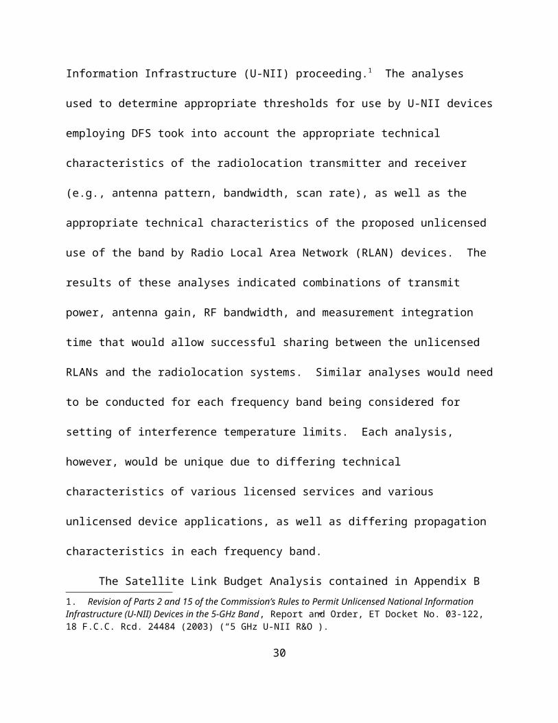
Table 8.
PolarizationPolarization Mismatch LossMonitoring Antenna Transmitted Signal
Horizontal Vertical Greater than 20 dBHorizontal Circular 3 dB
Vertical Horizontal Greater than 20 dBVertical Circular 3 dBCircular Horizontal 3 dBCircular Vertical 3 dB
Circular (Left Hand) Circular (Right Hand) Greater than 25 dBCircular (Right Hand) Circular (Left Hand) Greater than 25 dB
As it can be seen from Table 8, the error resulting from using different polarizations for
the monitoring system can result in a significant underestimation of the measured signal. It
should also be pointed out that the polarization of an antenna remains relatively constant
throughout the main lobe of the antenna pattern, but can vary considerably in the minor lobes,
which could result in additional measurement errors.6
Taking the above factors into consideration, achieving finer resolution to account for
minimum receiver bandwidths or minimum receive antenna beamwidths would appear to be
necessary to ensure that an interference temperature limit is established that provides adequate
protection to all licensed user’s receivers. However, if an interference temperature monitoring
receiver utilizes narrow bandwidths and beamwidths, the increases in the number of observation
points, both in frequency and azimuth sweeps, would greatly increase the total sweep time and
would introduce latency in the update rate for unlicensed transmitters depending on real-time
information from the monitoring stations. For example, increasing the total sweep time would
increase the likelihood that maximum actual interference temperature values are not measured in
a time-varying environment, such as for packet data systems, systems using antennas employing
beam forming techniques, or frequency hopping systems. This would further extend the time
Potentially Hazardous Electromagnetic Radiation at Microwave Frequencies, at 12 (April 20, 1973).6. Antenna Analysis, E. A. Wolff, at 17 (1966).
36

delay before interference above the interference temperature limit is detected and action is taken
by the unlicensed device.
Real-time or fixed interference temperature monitoring receivers could encounter spatial,
angular, temporal, and frequency limitations. Some of these limitations can be addressed by
establishing antenna heights, bandwidths, and antenna gain patterns and polarizations for the
monitoring receivers that are representative of the licensed user’s receiver. However, if
frequency and angular increments are too small, a time delay in measured interference
temperature levels may be introduced, where the licensed user would not be adequately protected
on a real-time basis. For mobile real-time monitoring systems and mobile licensed users, it is not
clear how the technical limitations raised above can be addressed. However, NTIA believes that
it is possible to resolve many of these technical issues if the locations of both the monitoring
system and licensed user are fixed.
XII. DOMESTICALLY AND INTERNATIONALLY DEVELOPED STANDARDS COULD BE USED FOR DEFINING THE PERMISSIBLE INTERFERENCE LEVELS FOR EACH RADIO SERVICE.
In the NOI, the Commission requests comment on whether a modest rise in the noise
floor of a receiver as envisioned by the interference temperature model, would generally not
cause harmful interference as defined under their definition of harmful interference.1 Comments
are sought on how much interference can be tolerated before it is considered harmful for a given
radio service in a given frequency band. If the determination of harmful interference is based on
a specific quality of service level, the Commission seeks comment on the rationale used to justify
this level. The Commission also requests that commenting parties identify the specific frequency
bands and services associated with these levels.2
1. NOI/NPRM at ¶ 27.
2. Id. at ¶ 28.37

The interference temperature metric as defined in the NOI is merely a measuring tool. It
could be used to identify how much interference exists in a particular band at a particular time in
a given geographical area. However, it does not determine whether the measured level of
interference is too high, too low, or just right. In order to use the interference temperature
metric, this determination will have to be made in many frequency bands across the RF
spectrum. To accomplish this in a way that promotes spectrum efficiency, provides protection to
incumbents, and that is predictable and non-arbitrary, a permissible interference standard is
needed, not just a new technical metric. The need for a permissible interference standard is
discussed in an article submitted as part of the public record for the SPTF.3 This article identifies
the lack of permissible interference standards in the Commission’s Rules as a problem and
proposes that such standards be developed, and suggests a framework to accomplish this
objective. This is consistent with the Commission’s stated objective of providing radio service
licensees with greater certainty regarding the maximum permissible interference in the frequency
bands in which they operate.4
One of the key steps in any interference, electromagnetic compatibility, or sharing
assessment is identifying an appropriate level of permissible interference. The identification of
the appropriate level is often confusing, time consuming, with no single reference source from
which to draw. Complications arise because of the divergent needs of incumbents and proposed
entrants into any frequency band. The complexity of this process is further complicated by the
numerous terms used regarding interference. For example, various fora including the NTIA, the
Commission, and the ITU-R define five terms relative to interference: Interference, Permissible
3. R. Paul Margie, Efficiency, Predictability, and the Need for an Approved Interference Standard at the FCC, 2003 Telecommunications Policy Research Conference (September 2003) (This article is available at http://stlr.stanford/stlr/articles/03_stlr_5/index.htm) (“Margie Article”).
4. NOI/NPRM at ¶ 1.38

Interference, Accepted Interference, Harmful Interference, and Protection Ratios. Other terms
that are commonly used, but not specifically defined are Allowable Performance Degradation,
Interference Protection Criteria, and Spectrum Sharing Criteria. Since the spectrum sharing
criteria normally depend upon specifics of the interfering and interfered-with systems, as well as
the types of interfering signals, a very large number of combinations are possible.
Permissible interference levels can be specified for aggregate (e.g., total from all sources
of interference) or single-entry interference. For a given radio service and type of system (e.g.,
communications, radar), the parameters listed in Table 9 should be considered in developing the
aggregate and single-entry permissible interference levels. The parameters listed in Table 9 will
vary depending on the radio service operating in a given frequency band. For example, in
developing permissible interference levels in the frequency bands used by the aeronautical radio
navigation service, the power thresholds would not be permitted to vary based upon time
duration of the interference, due to the safety-of-life functions of this service. On the other hand,
in the frequency bands used by the FS, power thresholds can be based on long-term and short-
term time percentages of interference.
Table 9.
Parameter Typical Units
Description
Power Threshold
dBm,dBW,
dB
Two or more levels of interfering signal power (I), interference-to-noise-ratio power ratios (I/N), or signal – or carrier-to interference power ratios (S/I or C/I)
Reference Bandwidth
Hz,kHz,MHz
Bandwidth in which interfering signal power should be calculated or measured.
Percentage of Time
Percent For each power threshold, the percentage of time during which the threshold should in the case of S/I or C/I or should not in the case of I
39

or I/N, be exceeded.Percentage of
LocationsPercent For each power threshold, the percentage of locations at which the
threshold should in the case of S/I or C/I or should not in the case of I or I/N, be exceeded. Used in some radio services to protect operations within a service area.
Special Conditions
Various Information needed for interpretation or application of the thresholds, including as a minimum whether the permissible interference is for aggregate or single-entry interference. The type of interfering signal for which the permissible interference level pertains to the I/N, S/I, or C/I thresholds the definition of the N, S, C reference levels. This may include the duration for which permissible interference can be exceeded; specific category of victim or interfering stations; and frequency off-tuning associated with the power thresholds.
It is possible to describe potentially interfering signals using a number of generic
categories. Table 10 provides a list of the generic categories that can be used to describe
potentially interfering signals. The permissible interference levels for a system operating in a
given radio service can vary depending on the types of interfering signal being received. For
example, GPS receivers operating in the RNSS are more susceptible to continuous wave (CW)
signals compared to noise-like signals and are less susceptible to interference from low-duty
cycle pulsed signals. This susceptibility to CW and robustness to pulsed interfering signals is
directly related to the signal structure of the GPS navigation signal.
Table 10.
Type of Interfering Signal
Definition
Continuous Wave A continuous signal with a bandwidth much smaller than the receiver baseband (output bandwidth).
Noise-Like A continuous signal that resembles Gaussian white noise over the radio frequency bandwidth of the receiver (uniform power spectral density) or produces the same effect as such a signal.
Pulsed A signal that is turned on and off over time defined by the time on (pulse width) and the repetition rate of the pulses. The pulses may occur at a constant or changing repetition rate.
Impulse A signal with very short duration pulses, generally less than 0.1 -2 nanoseconds in duration and occurring at constant or changing repetition rates.
Same as Desired Signal
A signal with modulation parameters that are the same as the desired signal except the baseband information content (carrier frequencies may differ).
40

NTIA recently completed the first phase of a study that reviewed existing standards and
identified available interference protection criteria (IPC) for the various radio services in the 30
MHz to 30 GHz frequency range.5 The study considered national and international standards
from the following organizations: ITU-R, TIA, RTCA, ICAO, ETSI, IEC, International
Maritime Organization, World Meteorological Organization, European Radiocommunications
Organization, Radio Technical Commission Maritime, Aerospace and Flight Test Telemetry
Coordination Committee, Institute for Electronic and Electrical Engineers, United Kingdom
Radiocommunications Agency, and Eurocontrol. Based on its review, NTIA determined that for
many of the radio services, the IPC values contained in the various publications were incomplete
and varied due to the specific type of interfering signal being received. During the second phase
of the NTIA study, emphasis will be placed on developing IPC or other criteria for frequency
sharing situations of practical importance. NTIA expects to publish these findings as well.
The Margie Article identified the need to establish consistent permissible interference
standards, and recommended that the Commission initiate a NOI on the subject.6 NTIA agrees
with this suggestion and recommends that the results of the first phase of the NTIA study on IPC
values for specific radio services be included as part of the NOI. The first phase of the NTIA
study represents a comprehensive review of existing national and international standards and can
serve as a solid basis for the Commission to begin building a public record with the goal of
establishing maximum permissible interference levels to promote predictability and certainty for
both licensed and unlicensed spectrum users.
XIII. DEFINING INTERFERENCE TEMPERATURE IN TERMS OF SIGNAL-TO-NOISE RATIO COULD PROVIDE GREATER FLEXIBILITY AND CERTAINTY THAT BOTH INCUMBENT AND FUTURE SPECTRUM USERS
5. NTIA expects to publish the results of this study later this summer.6. Margie Article at 38.
41

DESIRE.
In the NOI, the Commission requests comment on what elements should be considered in
setting interference temperature limits for different bands and locations.1 The Commission
suggests several factors such as type and criticality of service, its susceptibility to interference,
types of licensees, state of the development of technology, and propagation characteristics of the
frequency band that could be considered in setting interference temperature limits for a band.
The Commission seeks comment on whether these factors are appropriate as well as whether
other criteria should be addressed.2
For many active services, such as the broadcast service, existence (or lack thereof) of a
desired signal at some level above the measured noise floor can be used as an indication of
spectrum utilization. Desired signal strengths that are well in excess of maximum noise levels
(high S/N) might allow opportunistic underlay by unlicensed devices with a lower potential of
causing harmful interference to the licensed user. Non-existence of a desired signal above the
noise floor indicates that the spectrum is not currently being used in the location of the
measurement. Therefore no harmful interference could occur and opportunistic use could be
permitted. The geographic area in between these two extremes, however, is the area where
receivers are most vulnerable to interference (marginal S/N). Passive services, services using
low received signal strengths, such as satellite downlinks, and mobile services which do not
always operate in the same geographic region are not likely to lend themselves to this approach.
Appendix D investigates opportunities that can exist for unlicensed use in certain areas,
while protecting the locations that are potentially more sensitive to interference. These areas of
opportunity could be utilized by unlicensed devices that are capable of measuring the RF
1. NOI/NPRM at ¶ 21.
2. Id.42

environment, and making a determination to transmit based on whether excess margin or
insufficient desired signal exists, or a determination to not transmit if the desired signal level is
such that an increase in noise could potentially disrupt communications. NTIA believes that
defining the interference temperature in terms of the available S/N could provide greater
flexibility and certainty for both incumbent and future spectrum users.
XIV. IN ORDER TO MAXIMIZE THE USEFULNESS OF MEASURED INTERFERENCE TEMPERATURE LEVELS, THE PARAMETERS OF THE MEASUREMENT SYSTEM SHOULD BE STANDARDIZED.
In the NOI, the Commission requests comment on the approaches to be used for
measuring the interference temperature on a real-time basis, and in the case of interference
temperature derived from measurements at multiple fixed sites, communicating that information
to unlicensed devices that are required to protect the limit.1 The Commission also seeks
comment on the measurement system(s) and procedures to be employed in measuring the
interference temperature.2
In the NOI, the Commission describes how they envision that the measured interference
temperature levels can be used in underlaying unlicensed device operations. For example, the
interference temperature measurements performed by multiple fixed monitoring stations can be
combined at a central location. The combined data can then be distributed to unlicensed devices
that in turn could modify their operating characteristics (e.g., frequency, power) in response to
the RF environment that is represented by the interference temperature. Since the measured
interference temperature levels can be used to modify, on a real-time basis, the characteristics of
an unlicensed device that could have a direct effect on its compatibility with licensed users, the
1. Id. at ¶ 22.
2. Id.
43

properties of the measurement system must be defined in sufficient detail to ensure that the
appropriate interference temperature limits are applied to protect all licensed receivers.
The Naval Postgraduate School performed a literature and research study for the
Commission on the impact of noise on wireless communications.3 As part of this study, different
approaches to perform noise measurements were examined. Based on their assessment, it is
clear that in the design of a measurement system there are a number of diverse factors that must
be considered.
NTIA believes that the interference temperature measurement system should be a
spectrum analyzer (SA) based system that is computer controlled. A specialized front-end
should be implemented before the SA that includes an effective bandpass filter and a low noise
preamplifier. The low noise preamplifier is used to increase the dynamic range of the
measurement system and the bandpass filter is used to protect the low noise preamplifier from
being saturated by strong out-of-band signals. The critical parameters of the interference
temperature measurement system include detector function, measurement bandwidth, noise
figure, sensitivity, measurement time, and the measurement antenna.
A detailed discussion of each of the critical parameters of the interference temperature
measurement system is provided in Appendix C. NTIA recommends that the interference
temperature measurements be made using both peak and root-mean-square (RMS) detector
functions. As discussed in Appendix C, the RMS detector provides a true representation of the
average power and the interference impact to most licensed receivers can be quantified in terms
of average power. The resolution bandwidth (RBW) of the measurement system should be
consistent with the IF bandwidth(s) of the licensed receiver(s) operating in the frequency band
3. Naval Postgraduate School, NPS-EC-02-004, Literature Search and Review of the Impact of Noise on Wireless Communications (March 2002) (“Naval Postgraduate School Report”).
44

being monitored. The video bandwidth employed should be as wide or wider than the RBW to
avoid the problems associated with video averaging that are discussed in Appendix C. The
preamplifier used in the front-end of the SA based interference temperature measurement system
establishes the measurement system’s noise figure, sensitivity, and dynamic range. As with the
bandwidth, the noise figure of the measurement system used to perform the interference
temperature measurements should be representative of that used by the licensed receivers
operating in the measured frequency band. In frequency bands where the signal activity is highly
dynamic (e.g., land mobile bands), a swept frequency approach can be used to monitor the band.
However, in frequency bands where the signals occur on a periodic basis (e.g., radiolocation
bands), a stepped frequency approach may be more appropriate. The measurement interval to be
used in either the stepped or swept frequency approach is difficult to estimate without prior
knowledge of the RF signal environment that is being monitored or the receivers that are to be
protected. For example, it may be possible to estimate the measurement interval based on the
characteristics of the licensed signals (e.g., symbol length in a digital system), but in general it
will be necessary to perform preliminary measurements in a frequency band to determine the
appropriate measurement interval to be employed. The antenna to be used to measure the
interference temperature levels should have a gain pattern that is consistent with the antennas
employed by the licensed user operating in the frequency band being monitored. A discussion of
the different types of commercially available measurement antennas is provided in Appendix C.
Since noise measurements are statistical in nature, first order statistics such as amplitude
probability distributions (APDs) could be used to characterize and understand the effect of the
measured signals on the licensed receivers. Higher order statistics can also be used to further
characterize the RF signal environment. This would require use of a spectrum analyzer capable
45
of sampling the time waveform of the received signal(s), and possibly other more specialized
equipment.
NTIA believes that the criticality of defining the measurement system parameters is
directly related to how the interference temperature measurements are going to be used. For
example, if the measured interference temperature levels are to be used to gain a gross
understanding of the signal occupancy in a frequency band, then some of the measurement
system parameters may be less important. However, the Commission indicates in the NOI that
the measured interference temperature levels can be used by unlicensed devices to control their
operating characteristics. In this situation, the parameters of the measurement system become
more critical and must be considered very carefully to ensure that interference temperature
measurements adequately protect the licensed receivers. Therefore, NTIA recommends that the
parameters of the interference temperature measurement system that are discussed above be
identified for each frequency band and standardized. NTIA believes that standardizing the
measurement system will maximize the usefulness of the measurements.
XV. BEFORE IMPLEMENTING THE INTERFERENCE TEMPERATURE MODEL, THE RIGHTS AND RESPONSIBILITIES OF BOTH LICENSED AND UNLICENSED SPECTRUM USERS MUST BE DEFINED.
The SPTF Report addresses the subject of spectrum rights and responsibilities and
recommends that the Commission define these rights and responsibilities for all spectrum users,
particularly with respect to interference and interference protection, and those rights and
responsibilities should be considered and established to the extent possible and practical.1 In the
NOI, the Commission seeks comment as to how this objective can be accomplished and avoid
long, drawn out interference disputes without detrimentally affecting reasonable expectations of
1. SPTF Report at 18.
46

all interested parties, including expectations regarding the Commission’s use of its authority to
impose conditions, modify licenses and take other steps to promote greater access to, and more
efficient use of the spectrum.2
Throughout the Commission’s SPTF and NTIA’s Spectrum Summit, providing
predictability and certainty for licensed and unlicensed, as well as incumbent and new users of
the spectrum, was identified as a critical goal to effectively manage the RF spectrum. Providing
predictability and certainty to all spectrum users can only be accomplished if the rights and
responsibilities of spectrum users are clearly defined. Several examples exist where the lack of
definition in the rights and responsibilities of the incumbent and new spectrum users appear to
have resulted in problems with deployment of new commercial services, including the General
Wireless Communications Service (GWCS), the Wireless Communications Service (WCS), and
the 700 MHz Commercial Mobile Radio Service (CMRS). For GWCS and WCS, flexibility of
use was stressed over clearly defined service rules, which resulted in spectrum below 5 GHz
where little or no commercial applications have been deployed.3 In the case of 700 MHz CMRS,
the uncertainty regarding when and how the broadcasters were to vacate the spectrum has
resulted in delays of the auction and deployment of commercial services.
One of the major findings and recommendations of the SPTF was that regulatory models
must be based on clear definitions of the rights and responsibilities of both licensed and
unlicensed spectrum users, particularly with respect to interference and interference protection.4
2. NOI/NPRM at ¶ 19. 3. The GWCS auction was indefinitely postponed due to lack of interest and the WCS auction generated minor interest and licenses were awarded for as low as $1.
4. SPTF Report at 3.
47

The SPTF also concluded that there are certain common elements that the Commission should
incorporate into its spectrum policy regardless of the regulatory model that is used, including
clear and exhaustive definition of spectrum users’ rights and responsibilities.5 It is expected that
clear definitions of rights and responsibilities of spectrum users would simplify the rulemaking
process, and could prevent heated public disputes over potential interference.6 In addition to
these recommendations of the SPTF, spectrum rights were also a major point of discussion in the
NTIA Spectrum Summit.7
NTIA believes that a clear definition of both spectrum rights and responsibilities would
facilitate a simplified technical process for considering new services, whether licensed or
unlicensed, in many frequency bands. Clearly defined rights and responsibilities will also
simplify the analysis of whether new unlicensed services can and should be introduced in
licensed bands. NTIA recommends that before the interference temperature model is
implemented, the rights and responsibilities of spectrum users be addressed. This could be
accomplished as part of the ongoing interference temperature rulemaking proceeding or as part
of the recommended NOI to identify permissible interference levels.
XVI. TO EFFECTIVELY IMPLEMENT THE INTERFERENCE TEMPERATURE MODEL, REPRESENTATIVE OPERATIONAL SCENARIOS MUST BE DEVELOPED FOR EACH RADIO SERVICE.
In the NOI, the Commission seeks comment on what assumptions should be made
regarding operating scenarios to be used when performing interference studies assessing how
much interference can be tolerated before it is considered harmful. The Commission also seeks
5. Id. at 4.6. See Testimony of Dr. Paul Kolodzy, Former Director of the Spectrum Policy Task Force, Federal Communications Commission, Before the U.S. Senate Committee on Commerce, Science and Transportation, Thursday, March 6, 2003.
7. See Keynote Address of Assistant Secretary Nancy J. Victory, Before the Federal Communications Bar Association (FCBA), Spectrum Policy Summit & CLE, Washington, DC, April 16, 2002.
48

comment on whether a statistical approach can be developed to arrive at the interference
temperature limits. If a statistical approach can be developed, commenters should identify what
parameters need to be developed. The commenters should also explain how such a statistical
approach would be applied.1
In assessing potential interference to receivers from transmitters, a source-path-receiver
analysis is often performed. The basic parameters that must be defined for this type of analysis
include the maximum permissible interference level, the output power and antenna gain of the
potentially interfering transmitter, the propagation path defined by a minimum separation
distance between the transmitter and receiver, and the gain of the receive antenna in the direction
of the potentially interfering transmitter. Collectively, this information defines an operational
scenario, which establishes how close the transmitter and receiver may come to one another
under actual operating conditions, and likely orientation of the antennas. This information is
used to determine the appropriate model to use in computing the propagation loss. The
operational scenario can also be used to determine the applicability of other factors such as
building attenuation, allowance for multiple transmitters, and safety margins.
The operational scenarios considered using the source-path-receiver approach typically
assume that the parameters (e.g., transmitter power, antenna gain) are represented by a single
fixed value. However, a probabilistic approach can also be employed, in which the analysis
treats the parameters as statistical quantities, each defined by a mean and deviation around the
mean. This analysis method could be employed by choosing or deriving a Probability
Distribution Function (PDF) for each parameter. The joint PDF can be computed by convolving
1. NOI/NPRM at ¶ 28.49

the individual PDFs with one another. The main difficulty with this approach is collecting a
sufficient amount of data to accurately develop the PDFs for the parameters in the analysis. For
radio services that require a high degree of confidence in the analysis results, such as the
aeronautical radionavigation service, there is little benefit in employing this approach since the
higher probabilities as defined by the PDF (e.g., 99.99999%) must be used to develop the
statistics for the analysis parameters.
Analyzing operational scenarios with consideration of locations of licensed receivers and
unlicensed transmitters has been a major difficulty in past rulemaking proceedings.2 In
particular, analyses considering mobile services (licensed and unlicensed), where the locations of
the transmitters are unknown, rely upon assumptions concerning separation distances that might
or might not be appropriate. Such radiocommunication services might be better analyzed by
considering interference scenarios, and the probability that harmful interference will occur, by
employing Monte Carlo analysis techniques.3 Using Monte Carlo analysis techniques, the worst-
case scenarios, as well as less conservative scenarios, can be taken into account in assessing
potential interference to a receiver. This approach was used in the 5 GHz U-NII R&O, where the
location of the radar receiver, unlicensed device transmitter locations, and shielding losses were
treated as random variables. Using this approach, propagation effects for locations that
accounted for nearly free-space propagation, as well as other locations that warranted greater
propagation losses due to terrain and shielding effects, were taken into consideration in assessing
potential interference to radar receivers.
2. The Margie Article contains a discussion of how vagueness and inconsistency in the rulemaking process affected the Multichannel Video Distribution and Data Service and Ultrawideband technologies rulemaking proceedings. See Margie Article at 20.
3. The Monte Carlo method has been used for the simulation of random processes and is based upon the principle of taking samples of random variables from their defined probability density functions.
50

In assessing potential interference to receivers using the interference temperature model,
it will be necessary to develop radio service specific operational scenarios. Currently most of the
efforts in developing documented operational scenarios for assessing potential interference to
receivers have been limited to the aviation industry. For example, RTCA Special Committee
159 (SC-159) Working Group 6 (WG 6) developed an operational scenario used to assess
potential interference to aviation GPS receivers used for a Category I precision approach from
MSS mobile earth terminals (METs).4 In this operational scenario, a minimum separation
distance of 100 feet was established and the free space model was determined to be appropriate
to compute the propagation loss. The GPS receive antenna was assumed to be located on top of
the aircraft and the antenna gain in the direction of the MET taking into account shielding from
the aircraft was established. The maximum permissible interference level was based on a GPS
receiver operating in the tracking mode, receiving a signal from a low elevation satellite, and a
noise-like interfering signal. A safety margin was also included in the analysis to account for
uncertainties such as multipath, receiver implementation losses, and variations in the antenna
gain. This operational scenario only considered interference from a single interfering transmitter
and did not consider interference from multiple transmitters of the same radio service or
transmitters from multiple radio services. RTCA SC-159 WG 6 has expanded the scope of their
work to include additional aviation scenarios as well as potential interference from multiple
interfering transmitters within the same radio service and from transmitters in multiple radio
services.5 In order to develop interference temperature limits for each radio service, the
4. Document No. RTCA/DO-235, Assessment of Radio Frequency Interference Relevant to the GNSS (January 27, 1997).
5. Document No. RTCA/DO-235A, Assessment of Radio Frequency Interference Relevant to the GNSS (December 5, 2002).
51

operational scenarios and appropriate assumptions for each will need to be developed. These
operational scenarios will be different for each radio service and must include information
regarding transmitter and receiver parameters such as locations, transmitter power, transmit and
receive antenna gains and any other radio service specific parameters (e.g., safety margin for
aviation). NTIA believes that operational scenarios employing statistical techniques can be used
for considering aggregate interference especially when the number and location of the
transmitters are unknown. However, it must be realized that if a licensed service is to provide
consumers with robust, reliable services, the probability of interference occurring must be kept
low. NTIA recommends that operational scenarios be developed for each radio service to be
used in determining the interference temperature limits. NTIA believes that adoption of radio
specific operational scenarios in conjunction with maximum permissible interference levels will
provide the certainty and predictability that incumbent and new users of the spectrum desire and
is consistent with the recommendations of the Commission’s SPTF.
XVII. THE INTERFERENCE TEMPERATURE LIMITS MUST PROTECT BOTH IN-BAND AND ADJACENT BAND SPECTRUM USERS.
In the NOI, the Commission’s request for comments only addresses interference to in-
band spectrum users and does not specifically address issues related to users operating in the
adjacent bands. In the NPRM, the Commission does address the issue of out-of-band emissions.
Specifically, the Commission recognizes the need to assure that increased operation of
unlicensed devices enabled under the interference temperature model will not result in harmful
out-of-band interference.1
Currently, adjacent band operations are protected by unwanted (i.e., out-of-band and
1. NOI/NPRM at ¶ 49.
52

spurious) emission limits that are either described as an absolute power or EIRP level, or as a
reduction in power level as the frequency becomes farther removed from the fundamental
frequency of the emission. Adequate measures of adjacent band energy must be included in the
interference temperature model if the adjacent band users are to benefit from the same levels of
protection that they are afforded under the current rules. This protection could arise from
specifying the frequency roll-off, as is done in current regulations, or by defining the temperature
limit that unwanted emissions must meet to successfully operate under the interference
temperature model.
A separate but equally important issue with respect to adjacent band emissions is how to
take them into account when establishing the interference temperature limit within a frequency
band. Because, even if the interference temperature limit in a particular band is well below the
permissible limit, an unlicensed device’s unwanted emissions could cause the interference
temperature limit in an adjacent band to be exceeded, particularly if the interference temperature
in the adjacent band is very close to the permissible limit and reflects the cumulative effect of
many unlicensed devices. For example, in the RNSS frequency bands used by GPS there are no
in-band, ground-based transmitters permitted. However, there is a concern that the cumulative
effect from transmitters operating outside the RNSS bands can impact the GPS receiver noise
floor. The potential sources of interference to GPS receivers include adjacent band emissions
from MSS METs; harmonic emissions from television transmitters; spurious and harmonic
emissions from 700 MHz commercial base, mobile, and portable transmitters; and unwanted
emissions from unlicensed devices. These multiple sources of potential interference, which
might individually be tolerated by a GPS receiver, could combine under certain circumstances
(e.g., close separation distances, operating at the maximum allowable out-of-band emission
53

level) to create an aggregate interference level that could prevent the reliable reception of the
GPS signal.
NTIA believes that if implemented properly, the interference temperature model can be
used to protect adjacent band licensed systems. NTIA recommends that when establishing the
interference temperature limits the emissions from licensed and unlicensed systems operating in
adjacent or harmonically related frequency bands be taken into consideration.
XVIII. ADDITIONAL PROVISIONS ARE NOT NECESSARY TO PROTECT DEEP SPACE NETWORK RECEIVERS IN THE 12.75-13.25 GHz BAND LOCATED AT THE GOLDSTONE COMPLEX.
In the NPRM, the Commission proposes to permit unlicensed devices operating at a
maximum EIRP of 36 dBm in the 12.75-13.25 GHz frequency band. This band is allocated to
the federal and non-federal space research service for reception at Goldstone, California. The
Commission does not believe that its proposal will be detrimental to space research operations.
The Commission tentatively concluded that since Goldstone is located in a rural location with
natural shielding by virtue of its location in a valley, very few, if any, unlicensed devices would
be operated in locations that could impact its operations. The Commission requests comment on
this tentative conclusion.1
Every U.S. deep space mission is designed to allow continuous radio communications
with the spacecraft. Continuous 24-hour coverage for several spacecraft requires several earth-
based stations at locations that compensate for the earth’s daily rotation. The locations in Spain,
Australia, and California are approximately 120 degrees apart in longitude, which enables
continuous observation and suitable overlap for transferring the spacecraft radio link from one
complex to the next.
1. NOI/NPRM at ¶ 39.54

The National Aeronautics and Space Administration (NASA) Goldstone complex is
located on the U.S. Army’s Fort Irwin Military Reservation, approximately 72 kilometers (45
miles) northeast from the nearest populated city. The Goldstone complex is situated in semi-
mountainous, bowl shaped terrain to shield against radio frequency interference. The 70 meter
antenna is the largest, and therefore the most sensitive, Deep Space Network (DSN) antenna, and
is capable of tracking a spacecraft traveling more than 16 billion kilometers (10 billion miles)
from the Earth. Given the importance and the sensitivity of the DSN antenna an analysis was
performed to determine the impact on DSN receivers based on the Commission’s proposed EIRP
level for unlicensed devices operating in the 12.75-13.25 GHz frequency band. The results of
the analysis provided in Appendix B indicate that an unlicensed device operating at an EIRP
density of 36 dBm/MHz would have to be within approximately 16 km of a DSN antenna before
potential interference occurs. At an EIRP density of 36 dBm/20 MHz the separation distance
reduces to approximately 8 km.
Protection of the spectrum used by the DSN receivers is essential for safeguarding data
communications capabilities between spacecraft and the Goldstone tracking antennas. The
remote location of the Goldstone complex provides protection for the sensitive DSN receivers
from local interference. Given the geographically remote location of the Goldstone complex,
interference to DSN receivers will only be encountered when the unlicensed devices are operated
on the Goldstone complex by NASA or Department of Defense personnel. It is believed that the
existing spectrum coordination and monitoring activities will ensure that DSN receivers are
protected from interference caused by unlicensed device operations. Thus, NTIA agrees with the
Commission’s tentative conclusion, and no additional provisions are necessary to protect the
DSN receivers at the Goldstone complex.
55

XIX. TECHNICAL ISSUES RELATED TO THE COMPLIANCE MEASUREMENTS OF UNLICENSED DEVICES THAT EMPLOY THE INTERFERENCE TEMPERATURE MODEL MUST BE ADDRESSED.
Transmitters must be tested to show compliance with the applicable requirements before
they can be certified. For unlicensed transmitters, both the technical requirements and the test
procedures are specified in Part 15 of the Commission’s Rules. In the NOI, the Commission
discusses several actions that may be taken by an unlicensed device when its emissions cause the
interference temperature limits to be exceeded at the licensed receiver. For example, the
unlicensed device could select a different transmitting frequency; cease transmitting for a period
of time; decrease its power using automatic transmitter power control; or electrically re-shape its
antenna pattern.1 The NOI does not address technical issues related to compliance measurements
of unlicensed devices that employ the interference temperature model.
The technologies contemplated in this NOI reach far beyond the traditional
methodologies employed in device certification. For example, measurement of transmitter
power across a given frequency range is insufficient to ensure that dynamic systems are
functioning properly. Telecommunication Certification Bodies (TCB) are responsible for
performing the compliance measurements, including those of unlicensed devices operating under
Part 15 of the Commission’s Rules. The introduction of unlicensed devices employing the
interference temperature model will raise technical issues that need to be addressed specifically
with respect to the TCBs. In the Commission’s NPRM on cognitive radio technology, many of
the compliance measurement issues that will be encountered by devices employing interference
temperature are also being addressed.2 As indicated in the Commission’s NPRM on cognitive
radio technologies, many new technical issues must be resolved to show that a device is
1. NOI/NPRM at ¶ 13.
2. Cognitive Radio NPRM at ¶¶ 99-107. 56

compliant with the Commission’s Rules. Many of the same compliance measurement issues
must be resolved for devices employing the interference temperature model. For example, for
devices employing DFS, these technical issues can include determining the frequency bands that
are to be monitored, the monitoring bandwidth, the sensitivity of the monitoring receiver, the
ability of the device to select an operating frequency and power level based on the presence of
various standardized test input signals, the monitoring period and revisit time, and the time
required to move off of a frequency once the interference temperature limit is exceeded. For
devices employing geo-location techniques, compliance measurement issues related to the ability
to correctly identify their location based on geo-location technology and the ability to access a
database and correctly determine the location of authorized transmitters must be addressed.
TCBs must be required to develop new capabilities in both the test equipment available, and the
expertise of their technical staff in order to certify devices utilizing these new technologies.3
In the past, because of their simplicity, the compliance measurement procedures were
typically considered after the development of the service rules. However, given the complexity
of the devices that employ technologies capable of modifying operating characteristics that can
change their electromagnetic compatibility with other devices, the compliance measurement
procedures must be addressed at the same time the service rules are developed. The TCBs are
the experts in the area of performing the compliance measurements and need to be actively
engaged in providing guidance on the technical issues related to device certification. NTIA
believes that technological approaches that cannot be verified in the TCB laboratories should not
3. See 47 C.F.R. § 2.962 (b). Under the Commission’s Rules, to be designated as a TCB, the TCB is required to demonstrate expert knowledge of the regulations for each product with respect to which the body seeks designation. Such expertise includes familiarity with all applicable technical regulations, administrative provisions or requirements, as well as, the policies and procedures used in the application thereof. The TCB is required to have the technical expertise and capability to test the equipment it will certify.
57

be relied upon for successful spectrum sharing using the interference temperature model. NTIA
recommends that the Commission resolve the technical issues related to performing the
compliance measurements prior to implementing the interference temperature model.
XX. THE INTERFERENCE TEMPERATURE LIMITS IN A FREQUENCY BAND SHOULD BE BASED ON THE MOST SENSITIVE RADIO SERVICE OPERATING IN A BAND.
There are many instances where several radio services share the same frequency band on
a primary and secondary basis. In the frequency bands where several radio services share the
spectrum on a primary or secondary basis, the Commission requests comment on whether the
interference temperature limit should be based on all the licensed services or only on the service
that is most susceptible to interference.1
In frequency bands where several radio services share the spectrum on a primary or
secondary basis, the interference temperature limit for unlicensed devices should be established
to protect all licensed services. If this approach is not used, unlicensed devices would enjoy a
higher status than the secondary services operating in the band. This would result in less, not
more regulatory certainty for the incumbent services than under the current regulatory
framework. The primary service in a frequency band is not always the most susceptible to
interference. In the particular case of radio astronomy, observations are carried out successfully
in several bands where the radio astronomy service has a secondary allocation, and is the most
sensitive service. For example, the 14.47-14.7145 GHz band is shared between the fixed,
mobile, and fixed satellite services on a primary basis with radio astronomy operations on a
secondary basis. In this band, extensive coordination agreements or other regulatory approaches
can be used such that the secondary radio astronomy operations can co-exist with the other
1. NOI/NPRM at ¶ 21.58
primary services, which is not possible with unlicensed devices. If the interference temperature
in the 14.47-14.7145 GHz band were based on only the primary services, the permissible level of
interference could be approximately 72 dB higher than the level necessary to protect the radio
astronomy observations.2 If an interference temperature limit is established in a band in which
both primary and secondary allocated services operate, NTIA recommends the limit should be
based on the most sensitive radio service operating in the frequency band.
XXI. INTERFERENCE TEMPERATURE MEASUREMENTS MADE BY A SATELLITE RECEIVER CANNOT BE USED TO PROTECT GROUND-BASED RECEIVERS.
In the NOI, the Commission describes a number of approaches to perform adaptive or
real-time interference temperature measurements by which monitored information regarding
spectrum occupancy could be transmitted back to individual unlicensed devices.1 For example,
the Commission believes that satellites could monitor the ΔT/T and make the measured data
available to individual devices, which in turn could adjust their operation to ensure that they do
not interfere with licensed operations. The Commission requests comment on the utility and
potential benefits of such a real-time monitoring approach in the 6525-6700 MHz and 12.75-
13.25 GHz bands, as well as other frequency bands. Comments are also requested on how the
monitored information could be acquired by the unlicensed devices.2
The interference level at a satellite receiver that results from a large number of ground-
based unlicensed devices operating within the footprint of the satellite will cause an increase in
2. The permissible interference level for land mobile operations is approximately -146 dBW, whereas the maximum permissible interference level to protect radio astronomy operations, based on Recommendation ITU-R Recommendation RA.769 in the 14.44-14.5 GHz band, is -218 dBW.
1. NOI/NPRM at ¶ 37.
2. Id. at ¶ 51.
59

the ΔT/T level in the satellite receiver. The effective interference at the satellite receiver would
be an aggregate from a large number of unlicensed devices. This aggregate signal results from
ground-based devices where each device is essentially the same distance from the satellite
receiver, thus there cannot be a single dominant device. However, the measured ΔT/T level at
the satellite receiver is only applicable for assessing potential interference to a satellite receiver.
In the case of the ground-based radio services (e.g., fixed, mobile), the potential interfering
unlicensed devices can operate in close proximity to the ground-based receiver. Unlike
interference to a satellite uplink receiver, a single unlicensed device could be the dominant factor
in establishing the effective interference power level at a ground-based receiver. The
interference interactions between satellite and ground-based receivers and ground-based
unlicensed devices are completely different. Thus, it does not appear possible to use the
interference levels measured by a satellite receiver to control the operating characteristics of
unlicensed devices to the extent necessary to protect licensed ground-based receivers.
Using satellites to make measurements of the noise within a frequency band has been
ongoing for years. Government and commercial satellite systems monitor geophysical,
metrological, and environmental conditions on the Earth. These satellite systems are capable of
measuring small changes in the noise, and the data is downloaded (not on a real-time basis) for
use in long-term weather prediction models. However, using this measured data on a real-time
basis to control the operating characteristics of a ground-based transmitter has not been
attempted. Recently, a system has been proposed by Mobile Satellite Ventures (MSV) that will
monitor ancillary terrestrial component (ATC) emissions within the footprint of their satellite.3
The purpose of this monitoring is to provide assurance that the level of ground-based co-channel
3. Mobile Satellite Ventures Ex Parte Presentation, IB Docket No. 01-185, Monitoring and Control of Ancillary Terrestrial Emissions by MSV’s Space Segment (March 28, 2002).
60

interference (e.g., ΔT/T) as seen by other satellite systems remains below acceptable levels. In
the MSV proposal the aggregate signal level at a particular co-channel frequency generated by
ATC operations within each satellite cell will be monitored. By combining the co-channel
contributions from all satellite cells containing ATC components, the total (aggregate) co-
channel signal generated by the entire ATC network can be measured and recorded. Using a
closed-loop feedback control, a centralized controller can set the appropriate limits on ATC
emissions if interference begins to approach a specified level. The proposed monitoring system
will use logarithmic amplification to detect relatively small changes in the noise floor.4 The
proposed monitoring system will also have the means to self calibrate to noise levels in the
absence of ATC emissions. MSV specifically states that the monitoring and control of ATC
emissions can only work in a satellite system that is completely integrated and coordinated
between the space and ground-based segments with the real time control of information between
the two.5 The approach being proposed by MSV appears to be similar to that envisioned by the
Commission. MSV plans to use this approach to ensure that their ATC system does not interfere
with in-band Inmarsat operations. NTIA recommends that the Commission monitor the MSV
system as it is implemented, and possibly establish a limited test program in the 6 or 13 GHz
frequency bands based on this approach.
It appears there are possible approaches that can be used to make measurements of ΔT/T
levels in frequency bands used by satellite uplinks. However, it is unknown if the measured
ΔT/T levels can be used to prevent unlicensed ground-based transmitters from interfering with a
satellite receiver, especially if the satellite and ground-based transmitters are not operating under
a central controller. For example, if the ΔT/T limit is exceeded, it is unclear what factors would
4. Id. at 3, 13.
5. Id. at 3.61

be used to determine which devices would modify their operating characteristics (e.g., turn off
all or some percentage of devices, incrementally reduce power for all devices). NTIA believes
that the interference interactions between satellite and ground-based receivers and ground-based
unlicensed devices are completely different. Thus, NTIA does not believe it is possible to use
the ΔT/T levels measured by a satellite receiver to control the operating characteristics of
unlicensed devices to the extent necessary to protect licensed receivers operating in frequency
bands used by the ground-based radio services (e.g., fixed, land mobile, radiolocation).
XXII. BASELINE MEASUREMENTS IN SELECTED LICENSED AND UNLICENSED FREQUENCY BANDS SHOULD BE PERFORMED BEFORE DECIDING WHETHER OR NOT THE INTERFERENCE TEMPERATURE MODEL CAN BE IMPLEMENTED.
The Commission states that the noise floor has increased at various points, which are
indicated by peaks above the original noise floor shown on Figure 1 in the NOI.1 In between the
peaks, the level is close to the original noise floor. The Commission believes that by allowing
the entire noise floor in a band to increase to the levels represented by the peaks, greater access
by higher-powered unlicensed devices is possible. The Commission proposes that the
interference temperature limit should be set at this elevated noise level.2
There are two problems with the interference temperature model as proposed by the
Commission. First, increasing the overall noise level in a frequency band will not necessarily
permit more opportunistic use of the spectrum by higher-powered unlicensed devices. As shown
in Appendix E, an elevated noise level will impact both licensed and unlicensed users equally.
Therefore, if the noise is elevated, a higher transmitter power is necessary to achieve the same
range that was obtainable in a lower noise environment. The study performed by the Naval
1. NOI/NPRM at ¶ 15.
2. Id.
62

Postgraduate School reviewed a limited set of measured data in the 2.4 GHz unlicensed band and
stated that there is a serious concern about saturation of the present unlicensed bands and the
degradation in system performance that accompanies spectrum saturation.3 The Commission’s
Technical Advisory Council (TAC) also raised Concerns regarding the degradation of the noise
environment.4
The second problem encountered is the lack of measured data supporting the “original
noise level” or the “elevated peak levels” shown in Figure 1 of the NOI. As pointed out in the
Naval Postgraduate School Report, the largest body of environmental noise measurements was
developed by NTIA’s ITS.5 Although the ITS spectrum surveys provide an excellent database of
noise at the time the measurements were performed, the measurements were conducted prior to
the widespread deployment of many of the wireless radio services in operation today.6 As the
Naval Postgraduate School report points out, a similar set of measurements has not been
performed by the ITS in a number of years, and it is believed that the existing data is only of
limited historical interest.7 The Commission’s Interference Protection Working Group and TAC
also indicated that a better understanding of the existing noise environment is necessary.8
3. Naval Postgraduate School Study at 380.
4. Federal Communications Commission, Technical Advisory Council, Fourth Meeting Report, at 23, Annex 4 (March 24, 2000).
5. National Telecommunications and Information Administration, Institute for Telecommunication Sciences, NTIA Report 97-334, Broadband Spectrum Survey at San Diego, California (December 1996); National Telecommunications and Information Administration, Institute for Telecommunication Sciences, NTIA Report 97-336, Broadband Spectrum Survey at Los Angeles, California (May 1997); National Telecommunications and Information Administration, Institute for Telecommunication Sciences, NTIA Report 99-367, Broadband Spectrum Survey at San Francisco, California May-June 1995 (July 1999); National Telecommunications and Information Administration, Institute for Telecommunication Sciences, NTIA Report 95-321, Broadband Spectrum Survey at Denver, Colorado (September 1995).
6. Naval Postgraduate School Report at 380.
7. Id.
8. Federal Communications Commission, Spectrum Policy Task Force, Report of the Interference Temperature 63

Although based on a limited set of measured data, in one frequency band, the Naval
Postgraduate School Report does raise the issue of spectrum saturation and the possible
interference problems that could arise if the noise level is permitted to increase across a
frequency band. NTIA believes that the lack of basic information of the existing noise
environment greatly limits the ability of licensed and unlicensed system designers to conduct
practical and useful system performance analysis. To begin addressing these problems, NTIA
and the Commission should identify a list of candidate licensed and unlicensed frequency bands
in which the emission or noise levels can be measured using standardized measurement systems.
NTIA believes that these measurements can serve as a baseline for characterizing the existing
emission environment in those bands, which can be used to determine whether the interference
temperature model can be implemented in such a way as to achieve the Commission’s longer
term spectrum management objectives.
XXIII. CONCLUSION
NTIA commends the Commission for initiating this proceeding to examine possibilities
to expand the options for unlicensed device use while also providing certainty and predictability
desired by licensed spectrum users. NTIA agrees with the Commission regarding the significant
benefits that could be gained by increasing the spectrum access opportunities for unlicensed
devices. The implementation of the interference temperature model and the use of interference
mitigation techniques such as DFS and geo-location represent a shift in interference management
from the transmitter to the receiver. The NOI identifies many technically challenging issues that
must be addressed before the interference temperature model can be implemented in a frequency
band. These technical issues include, but are not limited to, the development of radio service
Working Group, at 28 (November 15, 2002); Federal Communications Commission, Technical Advisory Council, Sixth Meeting Report, at 9 (September 27, 2000).
64

specific reference receiver parameters, the development of radio service specific maximum
permissible interference limits and operational scenarios, and measurement of the existing RF
signal environment in order to establish a proper baseline. Until these technical issues and the
rights and responsibilities of licensed and unlicensed spectrum users have been resolved, wide
spread implementation of the interference temperature model will not possible. Because of the
sensitive nature of the operations in the restricted frequency bands, implementing the
interference temperature model would be difficult if not impossible. However, if the initial
implementation of the interference temperature model were limited to specific bands, for
example, bands which have been transferred from the federal government, many of the technical
issues listed above could be addressed and possibly resolved with minimal impact to incumbent
commercial and federal government users. NTIA believes that active interference mitigation
techniques such as DFS and geo-location hold great promise for facilitating sharing between
licensed and unlicensed spectrum users. However, these techniques should not be employed
until the supporting technical studies examining the specific characteristics of the licensed radio
services and the unlicensed device applications have been completed.
For the foregoing reasons, NTIA submits these comments
Respectfully submitted,
65

Michael D. Gallagher Kathy D. SmithAssistant Secretary for Chief CounselCommunications and Information
Fredrick R. WentlandAssociate AdministratorOffice of Spectrum Management
Mark Settle National TelecommunicationsEdward Drocella and Information AdministrationElectronics Engineers U.S. Department of CommerceOffice of Spectrum Management Room 4713
1401 Constitution Avenue, N.W.Washington, DC 20230(202) 482-1816
August 13, 2004
66

APPENDIX A
ASSESSMENT OF PROPOSED POWER LEVEL AND DETECTION THRESHOLD IN THE 6 GHz AND 13 GHz FIXED SERVICE
FREQUENCY BANDS
INTRODUCTION
This appendix assesses the feasibility of the Commission’s proposal for sharing between higher-powered unlicensed devices and fixed service (FS) systems in the 6 GHz and 13 GHz bands. The analysis considers an unlicensed device operating at an equivalent isotropically radiated power level (EIRP) of 36 dBm located 100 meters from the FS receiver.1 The unlicensed device employs Dynamic Frequency Selection (DFS) and has a detection threshold of -64 dBm.2 The DFS detection threshold of –64 dBm is based on technical studies assessing compatibility between 5 GHz radar systems and Unlicensed National Information Infrastructure (U-NII) devices.3 The FS transmitter power received at the unlicensed device is computed based on typical parameters for the FS link and compared to the proposed detection threshold. The transmitted signal from the unlicensed transmitter at the FS receiver is computed and compared to the interference-to-noise (I/N) threshold of –13 dB, which corresponds to a 5 percent increase in system noise in the receiver.4
1. Establishment of an Interference Temperature Metric to Quantify and Manage Interference and to Expand Available Unlicensed Operation in Certain Fixed, Mobile and Satellite Frequency Bands, Notice of Inquiry and Notice of Proposed Rulemaking, ET Docket No. 03-237, 18 F.C.C. Rcd. 25309, at ¶ 47 (2003).
2. Id.
3. Revision of Parts 2 and 15 of the Commission’s Rules to Permit Unlicensed National Information Infrastructure (U-NII) Devices in the 5-GHz Band, Report and Order, ET Docket No. 03-122, 18 F.C.C. Rcd. 24484 (2003).
4. ITU-R Recommendation F.1094 permits a 1 percent increase in system noise attributable to non-primary (unlicensed) interference sources, which corresponds to an I/N = -20 dB.

FS SYSTEM PARAMETERS
The parameters for the FS systems considered in this assessment are given in Table A-1.
Table A-.
Parameter Value6 GHz 13 GHz
Frequency 6600 MHz 13000 MHzTransmitter Power 30 dBm 30 dBm
Mainbeam Antenna Gain 44 dBi 44 dBiLine Loss 2 dB 2 dB
Antenna Height 50 m 50 mTransmitter/Receiver Bandwidth 40 MHz 40 MHz
Noise Figure 4 dB 4 dBPath Length 40 km 20 km
Antenna Mask 32-25 Log(Off-Axis Angle) 32-25 Log(Off-Axis Angle)Minimum Carrier-to-Noise Ratio 28 dB 28 dB
UNLICENSED DEVICE PARAMETERS
The parameters for the unlicensed device considered in this analysis are provided in Table A-2.
Table A-.
Parameter ValueEIRP 36 dBm
Antenna Gain 0 dBiAntenna Height 2 m
Transmitter Bandwidth 20 MHzDFS Detection Bandwidth1 1 MHz
1. The Commission’s proposal did not include a measurement bandwidth for the detection threshold. A bandwidth of 1 MHz is used consistent with the value used in the U-NII DFS device and radar analysis that determined the –64 dBm threshold.
A-2

ASSESSMENT OF PROPOSED DFS DETECTION THRESHOLD
The level of the FS transmitted signal received by the unlicensed device is computed using the following equation:
PU = PFS + GFS - LT - LP - LClutter - BWCF + GU (A-1)
where:PU is the FS transmitted power received by the unlicensed device (dBm);PFS is the transmitted power of the FS (dBm);GFS is the mainbeam antenna gain of the FS (dBi);LT is the insertion loss for the FS transmitter (dB);LP is the propagation loss (dB);LClutter is the clutter loss (dB);BWCF is the loss due to the difference between the FS transmit and detection measurement bandwidths (dB); GU is the antenna gain of the unlicensed device (dBi).
In this assessment, the Irregular Terrain Model (ITM) is used to compute the propagation loss. 1 The parameters used in the ITM propagation model are shown in Table A-3.
Table A-.
Parameter ValueFrequency 6600 MHz, 13000 MHz
Polarization VerticalFS Transmitter Site Criteria Careful
Unlicensed Device Receiver Site Criteria RandomDelta H 10 meters
Dielectric Constant 15Surface Refractivity 301 N-Units
Conductivity 0.005 S/mRadio Climate Continental TemperatePercent Time 10%
Percent Location 50%Confidence Level 50%
Mode of Variability Mobile
1. National Telecommunications and Information Administration, Institute for Telecommunication Sciences, NTIA Report 82-100, A Guide to the Use of the ITS Irregular Terrain Model in the Area Prediction Mode (April 1982).
A-3

In the development of the -64 dBm detection threshold, the 5 GHz studies included a clutter factor that was randomly varied between 0 dB and 20 dB. In this assessment, a value of 13 dB is used for the clutter factor.
The level of the received signal from the FS transmitter will be reduced due to the mismatch in bandwidth between the FS transmitter of 40 MHz and the detection bandwidth of 1 MHz used in this assessment. The bandwidth correction factor is given by:
BWCF = 10 Log (1/40) = -16 dB
Using Equation A-1, the power level of the received FS transmitted signal at the unlicensed device is shown in Table A-4 for the 6 GHz and 13 GHz links.
Table A-.
Parameter Value6 GHz 13 GHz
PFS 30 dBm 30 dBmGFS 44 dBi 44 dBiLT -2 dB -2 dBLP -153 dB -138 dB
LClutter -13 dB -13 dBBWCF -16 dB -16 dB
GU 0 dBi 0 dBiPU -110 dBm -95 dBm
As shown in Table A-4, the computed FS transmitted signal power levels received by the unlicensed device are well below the proposed detection threshold of -64 dBm. Since the received FS transmitted power levels are below the detection threshold, a DFS equipped unlicensed device would sense that the channel is not being used and would be permitted to transmit.
A-4

ASSSESSMENT OF INTERFERNCE TO FS RECEIVERS FROM UNLICENSED DEVICES OPERATING AT THE PROPOSED POWER LEVEL
The power level of the unlicensed device transmitter at the FS receiver is computed using the following equation:
PR = EIRPU – LR - LFS - LClutter - BWCF + GFS (A-2)
where:PR is the unlicensed device transmitted power received by the FS receiver (dBm);EIRPU is the EIRP of the unlicensed device (dBm);LR is the insertion loss for the FS receiver (dB);LP is the propagation loss (dB);LClutter is the clutter loss (dB);BWCF is the loss due to the difference between the FS receiver and the unlicensed device bandwidths (dB); GFS is the gain of the FS receive antenna in the direction of the unlicensed device (dBi).
Since the unlicensed device is assumed to be operating 100 meters horizontally from the FS receiver, the free space propagation model given by the following equation applies:1
LP = 20 Log F + 20 Log D -27.55 (A-3)
whereLP is the free space propagation loss (dB);F is the frequency (MHz);D is the distance separation between the unlicensed device and the FS receiver (m).
Since there is a difference between the antenna heights of the unlicensed device and the FS receiver the slant range is used to compute the separation distance. The slant range is computed as follows:
D = (1002 + (50-2)2)1/2 = 111 meters
Since the separation distance is only 111 meters it is not appropriate to include a clutter factor.
The 40 MHz bandwidth of the FS receiver is larger than the 20 MHz unlicensed device transmitter bandwidth so the bandwidth correction factor is 0 dB.
1. For separation distances of less than 1 kilometer, the ITM propagation model defaults to the free space model.A-5

The FS receive antenna gain in the direction of the unlicensed device is a function of the off-axis angle which is computed as follows:
Off-Axis Angle = Tan-1 ((50-2)/100) = 25.6 degrees
Using the antenna gain mask from Table A-1, the FS receive antenna gain in the direction of the unlicensed device is:
GFS = 32 – 25 Log (25.6) = -3.2 dBi
Using Equation A-2, the power levels received at the FS receiver from the unlicensed device transmitter are shown in Table A-5.
Table A-.
Parameter Value6 GHz 13 GHz
EIRPU 36 dBm 36 dBmLT -2 dB -2 dBLP -89.7 dB -95.6 dB
LClutter 0 dB 0 dBBWCF 0 dB 0 dB
GFS -3.2 dBi -3.2 dBiPR -58.9 dBm -64.8 dBm
The noise power of the FS receiver is computed using the following equation:
N = -114 + 10 Log (RBW) + NF (A-4)Where:
N is the receiver noise power (dBm);RBW is the receiver bandwidth (MHz);NF is the receiver noise figure (dB).
Using the values of FS receiver bandwidth of 40 MHz and noise figure of 4 dB, the FS receiver noise power is -94 dBm.
The I/N is the difference between the power level of the unlicensed device transmitter at the FS receiver and the receiver noise power:
I/N = -58.9 - (-94) = 35.1 dB (6 GHz)
I/N = -64.8 - (-94) = 29.2 dB (13 GHz)
A-6

The computed I/N values exceed the -13 dB threshold by 48 dB (6 GHz) and 42 dB (13 GHz). In order to reduce the interference received from the unlicensed device transmitter to meet the interference threshold of -107 dBm (-94 dBm - 13 dB), either the EIRP level of the unlicensed device must be reduced or the separation distance between the unlicensed device and FS receiver must be increased.
The maximum allowable EIRP levels referenced to a 1 MHz bandwidth that the unlicensed device can have and still meet the interference threshold are:
36 - 48 + 10 Log (1/40) = -28 dBm/MHz (6 GHz)
36 - 29.2 + 10 Log (1/40) = -9.2 dBm/MHz (13 GHz)
These EIRP levels are below the proposal made by the Commission, but they are still higher than the general emission EIRP limit of -41.3 dBm/MHz currently permitted in this band under Part 15 of the Commission Rules.
If the unlicensed device has an EIRP level of 36 dBm, the separation distances from the FS receiver must be increased from 100 meters to 28 kilometers (6 GHz) and 14 kilometers (13 GHz).
In addition to an I/N, the carrier-to-interference (C/I) can also be used to assess potential interference to the FS receiver. The minimum carrier power level can be computed as follows:
Cmin = C/N + N = 28 + (-94) = -66 dBm (A-5)
The nominal carrier power at the FS receiver is computed using the following equation:
Cnom = PFS + GFS - LT - LP - LT + GFS (A-6)where:
Cnom is the nominal carrier power level at the FS receiver (dBm);PFS is the transmitted power of the FS (dBm);GFS is the mainbeam gain of the FS transmit antenna (dBi);LT is the insertion loss of the FS transmitter (dB);LP is the propagation loss (dB); GFS is the mainbeam gain of the FS receive antenna (dBi).
To compute the nominal carrier levels the parameters from Table A-1 and the ITM propagation model are used. The nominal carrier power levels and the available fade margins for the link considered in this assessment are shown in Table A-6.
A-7

Table A-.Parameter Value
6 GHz 13 GHzPFS 30 dBm 30 dBmGFS 44 dBi 44 dBiLT -4 dB -4 dBLP -140 dB -137 dBGFS 44 dBi 44 dBiCnom -26 dBm -23 dBmCmin -66 dBm -66 dBm
Fade Margin 40 dB 43 dB
As shown in Table A-6, the fade margins for the links considered in this analysis are not excessive.
The minimum carrier power computed using Equation A-5 and the interference power levels given in Table A-5 can be used to compute the available C/I ratio using the following equation:
C/I = Cmin - PFS = -66 - (-58.9) = -7.1 dB
C/I = Cmin - PFS = -66 - (-64.8) = -1.2 dB
These computed C/I values are much lower than the values necessary to provide reliable performance on any FS link.
CONCLUSION
The combination of DFS detection threshold and EIRP level proposed for unlicensed devices operating in the 6 and 13 GHz frequency bands are not adequate to protect FS receivers from potential interference.
A-8

APPENDIX B
ASSESSMENT OF POTENTIAL INTERFERENCE TO GOLDSTONE DEEP SPACE NETWORK OPERATIONS IN THE 12.75-13.25 GHz BAND
INTRODUCTION
This appendix assesses the potential interference from unlicensed devices operating at the maximum equivalent isotropically radiated power (EIRP) level of 36 dBm as proposed by the Commission to Deep Space Network (DSN) receivers in the 12.75-13.25 GHz frequency band.
INTERFERENCE CRITERIA
The interference criteria used in this analysis to assess whether the unlicensed device causes interference to the DSN receiver is based on ITU-R Recommendation SA.1157.1 In the 12.75-13.25 GHz band, a maximum allowable power spectral density of -220.5 dBW/Hz is specified. This interference criterion for the deep-space receiver is specified at the receiver input terminals.
ASSESSMENT OF INTERFERENCE TO DSN RECEIVERS
In this assessment, the distance separation required to preclude potential interference is computed based on the maximum EIRP level of 36 dBm proposed by the Commission and interference criteria specified in ITU-R Recommendation SA.1157.
The Commission’s proposal does not specify a bandwidth for the unlicensed device. Unlicensed device bandwidths of 1 MHz and 20 MHz are used to compute the EIRP density used in this analysis.
EIRPU = 36 dBm/MHz - 60 - 30 = -54 dBW/Hz (1 MHz)
EIRPU = 36 dBm/20 MHz - 73 - 30 = -67 dBW/Hz (20 MHz)
The required propagation loss to preclude potential interference is calculated using the following equation:
LP = EIRPU - IT (B-1)
where: LP is the required propagation loss necessary to preclude potential interference to the DSN receiver (dB);IT is the DSN receiver interference criteria (dBW/Hz);EIRPU is the EIRP density of the unlicensed device (dBW/Hz).
1. ITU-R Recommendation SA.1157, Protection Criteria for Deep-Space Research (1995).

Using Equation B-1 the values of required propagation loss are:
LP = 166.5 dB (1 MHz)
LP = 153.5 dB (20 MHz)
Using the required propagation loss, the Irregular Terrain Model (ITM) propagation model is used to determine the separation distance necessary to preclude potential interference to DSN receivers.1 The parameters used in the ITM propagation model are given in Table B-1.
Table B-1.
Parameter ValueFrequency 13000 MHz
Polarization VerticalUnlicensed Device Antenna Height 2 meters
DSN Receiver Antenna Height 10 metersUnlicensed Device Transmitter Site Criteria Random
DSN Receiver Site Criteria CarefulDelta H 100 meters
Dielectric Constant 15Surface Refractivity 280 N-Units
Conductivity 0.005 S/mRadio Climate DesertPercent Time 10%
Percent Location 50%Confidence Level 50%
Mode of Variability Mobile
Based on the ITM propagation model, the following approximate separation distances are necessary to preclude potential interference to the DSN receivers:
DReq = 16 km (1 MHz)
DReq = 8 km (20 MHz)
Since the nearest populated town is approximately 72 km away, the computed approximate separation distances are small enough where an unlicensed device would have to be operated by Department of Defense (DoD) or National Aeronautics and Space Administration (NASA) personnel at the Goldstone complex to result in potential interference to DSN receivers.
1. National Telecommunications and Information Administration, Institute for Telecommunication Sciences, NTIA Report 82-100, A Guide to the Use of the ITS Irregular Terrain Model in the Area Prediction Mode (April 1982).
B-2

Protection of the Goldstone radio frequency spectrum is essential for safeguarding data communication capabilities between spacecraft and the Goldstone tracking antennas. This spectrum protection is being successfully accomplished through mutual coordination between DoD and NASA. It is believed that this coordination and the existing spectrum monitoring activities will ensure that the DSN receivers are protected from unlicensed devices operating on the Goldstone facility.
B-3

APPENDIX C
DISCUSSION OF THE CRITICAL PARAMETERS OF THE INTERFERENCE TEMPERATURE MEASUREMENT SYSTEM
INTRODUCTION
This appendix discusses the different parameters that define the interference temperature measurement system. In general the interference temperature measurement system should be a spectrum analyzer (SA) based system that is computer controlled. A specialized front-end should be implemented before the SA that includes an effective bandpass filter and a low noise preamplifier. The low noise preamplifier is used to increase the dynamic range of the measurement system and the bandpass filter is used to protect the low noise preamplifier from being saturated by strong signals outside the passband. The critical parameters of the interference temperature measurement system include detector function, measurement bandwidth, noise figure, sensitivity, measurement time, and the measurement antenna. Statistical measurements of the signal environment are also discussed.
DETECTOR FUNCTION
Interference temperature measurements should be made using both peak and average detector functions. The peak detector function is used to measure the peak power level of a signal in a specified measurement interval. The average detector is a little more complicated, since “average” is a mathematically defined quantity, and many different averaging functions exist. These include, but are not limited to, linear average, logarithmic average, and root-mean-square (RMS) average.1 The different average detector functions tend to emphasize particular parts of the time waveform that is being measured. The logarithmic detector function gives greatest weight to the relatively lower values in the time waveform and thus discounts voltage peaks or spikes. The linear average detector tends to be more affected equally by the whole range of signal values. The RMS detector function is related to the “voltage-squared” values of the time waveform, and as such tends to be more affected by the highest signal levels of the waveform. However, this voltage-squared aspect is a measurement of the true average power of the signal. A study performed by NTIA’s Institute for Telecommunication Sciences (ITS) examined the effect of using different detector functions on measuring noise-like, pulse-like, and continuous wave signals.2 The ITS study generally concluded that the divergence in measured values for the various average detector functions are different for the three average detector functions, but they would be even greater for signals that contain spikes, such as out-of-band emissions from low-duty cycle pulsed or impulse signals. The study also concluded that the RMS detector gave the most accurate measure of the average power.3
1. The RMS detector determines the average power based on the RMS voltage levels that are measured.
2. National Telecommunications and Information Administration, Institute for Telecommunication Sciences, NTIA Report 01-383, The Temporal and Spectral Characteristics of Ultrawideband Signals (January 2001).
3. Id. at 8-13.

Another type of averaging, often referred to as “video averaging” is performed by using a relatively wide resolution bandwidth (typically about 1 MHz) and a narrow video bandwidth (as narrow as a few hertz). The idea behind this technique is to utilize a resolution bandwidth that is sufficiently wide to follow fluctuations of the signal in the pre-detection stages, and then to obtain an average value by smoothing the measured signal with a narrow post-detection low pass filter (the video bandwidth). In effect, this average suppresses the broadband content of the measured signal, allowing measurement of its narrowband, continuous-wave component, if any exists. To illustrate the potential problem with using the video averaging technique, measurements of emissions from microwave oven measured using video averaging indicated levels which were tens of decibels lower than the value that would have been indicated by wide bandwidth, peak detected measurements.4
MEASUREMENT BANDWIDTH
In the SA based measurement system, there are two bandwidths of concern: the resolution bandwidth (RBW) also referred to as the IF bandwidth and the video bandwidth (VBW) which is referred to as the post-detection bandwidth. To perform interference temperature measurements that are representative of the signal levels that a licensed receiver would experience, the measurements should be performed in a bandwidth that matches the licensed receiver IF bandwidth. This may be difficult since most SAs have a limited set of fixed RBWs.1 When the IF bandwidth of the licensed receiver does not match the available SA RBW, the RBW that is closest to matching the licensed receiver bandwidth should be employed. For example, if the licensed receiver has a IF bandwidth of 25 kHz it is appropriate to perform the interference temperature measurement using a RBW of 30 kHz. Performing the interference temperature measurement in a much wider RBW will reduce the sensitivity of the measurement.2
If narrower RBWs are employed it will take longer to measure across a given frequency range and time delays in the reported interference temperature measurements will exist. If there are multiple radio services operating in a frequency band or if adaptive bandwidth technology is employed it may be necessary to perform the interference temperature measurements in several RBWs. The VBW employed in the interference temperature measurement should be as wide or wider than the RBW.3 If the VBW is narrower than the RBW, the problems associated with the video averaging technique discussed earlier could be encountered.NOISE FIGURE AND SENSITIVITY
4. National Telecommunications and Information Administration, NTIA Report 94-303-1, Radio Spectrum Measurements of Individual Microwave Ovens Volume I, at 9 (March 1994).
1. SA RBWs may be selected from 0.01 to 3000 kHz, in a 1,3,10 progression. Modern SAs have RBWs as wide as 8 MHz.
2. Wider RBWs have higher noise levels which reduces the signal-to-noise ratio and the achievable sensitivity.
3. The rule-of-thumb is that the VBW should be three times wider than then RBW.
The preamplifier used in the front-end of the SA based interference temperature measurement system establishes the measurement system’s noise figure, sensitivity, and dynamic range.1 Since the noise figure of a SA is typically high (on the order of 20 to 30 dB), the overall noise figure of the measurement system is dominated by the noise figure of the first stage, which in this case is the preamplifier placed in front of the SA. By reducing the preamplifier’s noise figure and or increasing its gain the sensitivity of the measurement system will improve. In an optimized measurement system, the sum of the preamplifier gain and noise figure should be nearly equal to the noise figure of the SA across the frequency range to be measured.2 As with the bandwidth, the noise figure of the measurement system used to perform the interference temperature measurement should be representative of that used by the licensed receivers operating in the frequency band being monitored.
MEASUREMENT TIME
The measurement time includes both measurement interval on a specific frequency in a band and the time required to measure all of the frequencies in a segment of the spectrum. There are two approaches that can be used to measure the interference temperature across a band of frequencies: stepped frequency measurements and swept frequency measurements. In the stepped frequency approach the measurement consists of a series of individual measurements made at predetermined (fixed tuned) frequencies across a spectrum band of interest. The measurement system remains tuned to each frequency for a specified measurement interval referred to as the time step or dwell. The frequency interval for each step is typically set equal to the RBW of the measurement system. For each specified time interval the highest signal level occurring in that interval would be reported as the peak and the RMS is calculated based on the samples that occur during that interval. In the swept frequency approach the measurement system sweeps across the spectrum in individual segments that are referred to as spans. The frequency range of each span is then broken into individual frequency bins.1 As the SA sweeps across a selected span, it spends a finite amount of time measuring the received power in each of the bins.2 Within each measurement bin a single peak power level or RMS level is reported. The stepped frequency approach is typically used to capture peak signals occurring on an intermittent basis, such as a periodically scanning radar. The swept frequency measurement approach can be used to measure the peak and RMS levels in highly dynamic frequency bands,
1. The dynamic range is the difference, in dB, between the maximum and minimum acceptable signal level in a measurement system.
2. A higher noise figure results in loss of sensitivity; gain that is too low will fail to overdrive the measurement system noise, while gain that is too high will reduce the available dynamic range of the measurement system. The desirable gain of the preamplifier can be estimated as follows: GPA = NF + L + 5 dB; where NF is the noise figure in dB of the SA and L is the loss in dB in the cable connecting the preamplifier to the SA.
1. The number of bins is dependent on the SA. For example, Hewlett Packard SAs have 1001 frequency bins, whereas Agilent SAs have 601 bins.
2. For example, a 20 millisecond sweep time divided by 1001 measurement bins per sweep yields a 20 microsecond measurement time in each frequency bin.

such as the land mobile bands.
The measurement interval to be used in either the stepped or swept frequency approach is difficult to estimate without prior knowledge of the signal environment that is being monitored or the receivers that are to be protected. If the measurement interval is too short then reported values may not be accurate representations of the peak and RMS levels and the receiver may not be adequately protected. On the other hand, if the measurement interval is too long it will increase the time required to monitor a frequency band, introducing time delays in the reported interference temperature measurement levels. It may be possible to estimate the measurement interval based on the characteristics of the licensed signals. For example, if the licensed signal employs digital modulation with symbol or bit durations of 20 milliseconds, a measurement interval on the order of 20 milliseconds should be adequate to measure the RMS level and have a level that accurately represents the interference potential to that receiver. However, in general it will be necessary to perform preliminary measurements in a frequency band in order to determine the appropriate measurement interval to be employed.
MEASUREMENT ANTENNA
The antenna used to measure the interference temperature levels should have a gain pattern (e.g., omni-directional or directional) that is consistent with the antennas employed by the licensed user operating in the frequency band being monitored. Omni-directional, slant polarized, biconical antennas provide a good response to circular, vertical, and horizontal polarizations and are commercially available in the 0.1 to 20 GHz frequency range. A slanted-polarized log periodic antenna may also be employed if most of the radio activity is confined to an area subtending 180 degrees or less, relative to the measurement system. A variety of broadband cavity-backed spiral antennas have gain patterns that are most useful for directional measurements and are commercially available in the 1 to 18 GHz frequency range. Parabolic reflector antennas with a choice of feeds (linear, cross-polarized, and circular) are also an option for performing directional measurements.
STATISTICAL MEASUREMENTS
Receiver noise, which is stationary and Gaussian, can be characterized by one statistic, the mean temperature, and how it affects receiver performance, thus it is easy to define a noise temperature. For non-Gaussian noise such as impulsive processes, the mean temperature is not sufficient to adequately characterize the noise process and how it will affect receiver performance. In a study performed by ITS, using a simple matched filter receiver and Binary Phase Shift Keying modulation, it was found that receiver performance can be more severely degraded by non-Gaussian impulsive noise when compared to Gaussian noise, given the same mean temperature for both noise sources.1 This result emphasizes that mean interference temperature may not be sufficient to characterize the interference process and its effects on a particular receiver.
1. National Telecommunications and Information Administration, Institute for Telecommunication Sciences, NTIA Report 82-95, Digital System Performance Software Utilizing Noise Measurement Data (February 1982).

In addition to the peak and RMS measurements discussed earlier, amplitude probability distribution (APD) measurements should also be considered to characterize the signal environment.2 APD measurements represent first order statistics that have proven to be a valuable technique used to characterize white Gaussian noise processes.3 Interference from man-made noise processes are often more complex than white Gaussian noise processes, and may also require the use of higher order statistics for complete characterization to understand their effect on victim receivers.4 Measurements made with the peak and RMS detector functions represent two points on the APD curve. This would require use of a spectrum analyzer capable of sampling the time waveform of the received signal(s), and possibly other more specialized equipment.
2. APDs show the percentage of time that measured emissions exceed a given power threshold.
3. First order statistics accurately characterize variables that are independent and identically distributed.
4. Second order statistics measure the correlation between random variables.

APPENDIX D
DISCUSSION OF OPPORTUNITIES THAT CAN EXIST FOR UNLICENSED DEVICE USE IN CERTAIN AREAS, WHILE
PROTECTING THE LOCATIONS THAT ARE POTENTIALLY MORE SENSITIVE TO INTERFERENCE
INTRODUCTION
This appendix provides an alternative to the method of implementing the interference temperature model as proposed by the Federal Communications Commission in the Notice of Inquiry (NOI) portion of the interference temperature rulemaking.5 The alternative method is based on real-time measurement of desired (i.e. licensed) signal levels, and baseline measurements of noise levels existent in the frequency bands of interest. Existence (or lack thereof) of a desired signal at some level above the measured noise floor can be used as an indication of spectrum utilization. Licensed signal strengths that are well in excess of maximum noise levels (high signal-to-noise ratio (S/N)) could allow opportunistic use by unlicensed devices with a lower probability of causing harmful interference to licensed users. However, the high licensed signal level could present a challenge for the operation of the unlicensed service (i.e. operations in the presence of a high interfering signal level). Non-existence of a desired signal above the noise floor indicates that the spectrum is not currently being used in the location of the measurement. Therefore no harmful interference could occur and opportunistic use could be permitted. The geographic area in between these two extremes, however, is the area where receivers are most vulnerable to interference because the S/N is approaching the minimum usable value.
GENERIC COMMUNICATIONS SYSTEM STRUCTURE
Figure D-1 shows a block diagram that is typical of any radiocommunications link. This diagram is generic in that it does not show characteristics that are specific to a particular service, such as antenna type or pattern, antenna heights, and distance.
5. Establishment of an Interference Temperature Metric to Quantify and Manage Interference and to Expand Available Unlicensed Operation in Certain Fixed, Mobile and Satellite Frequency Bands, Notice of Inquiry and Notice of Proposed Rulemaking, ET Docket No. 03-237, 18 F.C.C. Rcd. 25309 (2003).
Figure D-1. Generic Communications Link Block Diagram
The generic equation that can be used to analyze the communications link in Figure D-1 is shown in Equation D-1 below:
(D-1)
Where:PR is the usable power at the receiver;PT is the transmitter output power;GT is the transmit antenna gain in the direction of the receiver;LP is propagation losses (including terrain, vegetation, buildings, etc.);GR is the receive antenna gain in the direction of the transmitter;GOTHER is the gains or losses unique to the design of the system, such as processing gain or fading losses.
The S/N in the receiver is then determined by comparing the usable received power level (PR) to the level of system noise (N). System noise is made up of thermal noise, as well as any undesired signal present in the receiver.
The bottom line in determining if a communication link is viable is determined by the S/N level within the receiver. Licensees must optimize the link equation to enable the particular type of service they wish to provide. That is, there must be sufficient S/N to use the received signal. Tradeoffs must be considered when optimizing the link equation to provide adequate service within acceptable costs.
PT: Increasing PT results in a corresponding increase in PR. The tradeoffs are greater cost, reducing frequency re-use, increasing radiation hazards, reducing battery life, and increasing equipment size.
GT: Increasing GT results in a corresponding increase in PR. The tradeoffs are greater cost, reduced gain in other directions, since increasing gain in one direction must result in decreasing gain in other directions (this could also be a benefit, depending on the type of service, since there would be more isolation toward off-axis receivers), and the physical size of directional antennas is typically larger than that of omni-directional antennas.
LP: Decreasing LP results in a corresponding increase in PR. This can be accomplished by increasing the antenna height (e.g. on a tower), reducing the amount of obstructions in the path (e.g., use an outside antenna), or by reducing the distance between the transmitter
Tx Rx
D-2

and receiver.
GR: Increasing GR results in a corresponding increase in PR. The tradeoffs are greater cost, reduced gain in other directions, since increasing gain in one direction must result in decreasing gain in other directions (this could also be a benefit, depending on the type of service, since there would be more isolation from off-axis interference), and the physical size of directional antennas is typically larger than that of omni-directional antennas.
GOTHER: Increasing GOTHER results in a corresponding increase in PR. Increasing other system gains, such as processing gains, can allow reception of signals that are not usable without this gain. The tradeoffs are greater cost, and greater complexity of systems employing these gain factors.
ALTERNATIVE METHOD FOR IMPLEMENTING THE INTERFERENCE TEMPERATURE MODEL
Because licensees have built their systems to operate in the level of noise currently present and provide service to customers within a certain coverage contour, any increase in noise will likely require compensation by an increase in one of the factors in the link equation or else system performance will be degraded. However, in areas where excess margin exists, or where insufficient signal exists for a usable communications link, opportunities for unlicensed use could more easily be exploited. This can be seen in Figure D-2.
D-3

Figure D-2. Opportunities for Spectrum Access in Areas With Excess Margin or Lacking Sufficient Signal-to-Noise (S/N) for Licensed Service.
As shown in Figure D-2, opportunities can exist for unlicensed use in certain areas, while protecting the locations that are potentially more sensitive to interference. These areas of opportunity (the shaded areas in Figure D-2) could be utilized by unlicensed devices that are capable of measuring the radio frequency (RF) environment, and making a determination to transmit based on whether excess margin or insufficient desired signal exist, or a determination to not transmit if the desired signal level is such that an increase in noise could potentially disrupt communications.
MEASUREMENT CHALLENGES
Interference temperature is proposed within the NOI to be defined as a measure of the RF power generated by undesired emitters plus noise sources that is present in a receiver system (I+N) per unit of bandwidth.1 Difficulty in measuring this quantity arises for several reasons.
First, the desired signal of the licensed service will be received along with any undesired
1. Id. at ¶ 10.D-4

signals. Hardware and/or software algorithms may be developed that are able to distinguish between a licensed desired signal and noise. Such a measurement process, however, would be very dependent on a detailed knowledge of the licensed signal. Requirement of such an in-depth knowledge of licensed signal structure could have a detrimental effect on the flexibility of a licensee, since any change in signal structure would potentially nullify any measurements made with the expectation of a different signal structure to be present.
Second, if interference temperature is to be referenced at the receiver, knowledge about the licensed receive antenna is required. This would include antenna location and main-lobe gain, as well as the shape of the antenna pattern, so that off-axis properties can be taken into consideration.
Finally, measurement of interference temperature at any location other than that of the licensed receiver location makes the assumption that the undesired signals and man-made noise are homogeneous in nature. This is not necessarily the case.
These challenges will likely exist no matter how the interference temperature model is implemented, and must be resolved to successfully allow unlicensed use without endangering licensed services.
D-5

APPENDIX E
ASSESSMENT OF THE POTENTIAL IMPACT OF INCREASING THE NOISE FLOOR
This appendix provides an assessment of the potential impact the increased noise, as discussed in the Federal Communication Commission (Commission) proposal of the interference temperature model, will have on licensed and unlicensed spectrum users. This assessment considers the link budget for interference from an unlicensed transmitter to a licensed user receiver and the link budget for an unlicensed link. It is assumed that the unlicensed transmitter is constrained to a relatively low equivalent isotropically radiated power level and thus would have to be close to the licensed user receiver to cause interference. The unlicensed transmitter would also have to be close to the unlicensed receiver to establish a communications link. Under this transmitter power constraint the elevated, background noise (Ne) shown in Figure 1 of the Commission’s Notice of Inquiry can be considered constant over the area of concern.1
In order for the unlicensed transmitter not to interfere with the licensed service the following link budget constraint must be satisfied:
PTU - CU-L - Ne = (I/N)L + LML (E-1)
where:PTU is the transmitter power of the unlicensed device;CU-L is the coupling loss from the unlicensed transmitter to the licensed receiver;Ne is the elevated background noise;(I/N)L is the required interference-to-noise ratio for satisfactory performance of the licensed link;LML is the available link margin for the licensed service.
The coupling loss includes antenna gains of the licensed and unlicensed transmitters and receivers, propagation losses, and any other additional losses (e.g., foliage, insertion). The link margin includes gains that are unique to the system, such as processing gain and represents the desired signal in excess of the minimum required signal.
Equation E-1 can be rearranged to determine the maximum allowable power level of the unlicensed device:
PTU = (I/N)L+ CU-L + LML + Ne (E-2)
1. Establishment of an Interference Temperature Metric to Quantify and Manage Interference and to Expand Available Unlicensed Operation in Certain Fixed, Mobile and Satellite Frequency Bands, Notice of Inquiry and Notice of Proposed Rulemaking, ET Docket No. 03-237, 18 F.C.C. Rcd. 25309 (2003).

If the unlicensed link is to satisfy the performance requirement, then the following link budget must be satisfied:
(PR/N)U = PTU - CU-U - LMU - Ne (E-3)
where: (PR/N)U is the required signal-to-noise ratio for satisfactory performance of the unlicensed link;CU-U is the coupling loss from the unlicensed transmitter to the unlicensed receiver;LMU is the available link margin for the unlicensed service.
Substituting Equation E-2 into Equation E-3 results in:
(PR/N)U = (I/N)L + CU-L + LML + Ne - CU-U - LMU - Ne (E-4)
The elevated, background noise level cancels out in Equation E-4. Therefore, the performance capabilities of the unlicensed device link are not impacted by an increasing noise floor. This is not an unexpected result. The increase in the noise floor does allow higher transmitter power as shown in Equation E-2; however, this higher transmitter power does not improve the performance of the unlicensed link as this unlicensed signal has to compete with the same increased noise level for satisfactory reception as shown in Equation E-3. The result is shown in Equation E-4 as performance that is independent of the elevated noise floor. This phenomenon needs further study before unlicensed devices are permitted to operate at higher-power levels based on consideration of an elevated noise level.
E-2