Embed Size (px)
Citation preview

raft
Draft Guidelinesfor the Assessment ofFormer Gasworks Sites

Published by:Environment Protection Authority59–61 Goulburn StreetSydneyPO Box A290Sydney South 1232Phone: (02) 9995 5000 (switchboard)Phone: 131 555 (information and publications requests)TTY: (02) 9211 4723Fax: (02) 9995 5999Email: [email protected]: www.epa.nsw.gov.au
The EPA is pleased to allow this material to be reproduced in whole or in part, providedthe meaning is unchanged and its source, publisher and authorship are acknowledged.
ISBN 0 7347 7554 7EPA 2003/01January 2003
Printed on recycled paper

iii
Preface
There are approximately 50 former gasworks sites in NSW. All these sites have high potential for contamination due to the chemicals, processes and by-products of the gas producing process.
These draft guidelines are prepared by the Contaminated Sites Section of the NSW Environment Protection Authority (EPA) to advise on and assist the process of assessing levels of contamination at former gasworks sites. The guidelines address the need for a systematic approach to assessing and managing contamination of gasworks sites so that they can be remediated for sensitive land use (e.g. residential accommodation) with minimum risk to public health and the environment.
The EPA anticipates that the guidelines will be used by environmental consultants, site auditors accredited under Part 4 of the Contaminated Land Management Act 1997 (CLM Act), local councils, industry and other interested groups.
Where a site auditor is involved in the assessment of gasworks sites, the EPA requires he or she to check the work of contaminated land consultants (‘consultants’) to ensure their work is consistent with these guidelines.
If you have inquiries about the draft guidelines, phone the Director, EPA Contaminated Sites Section, on (02) 9995 5000.
These guidelines will be finalised by mid-2003. Written comments are welcome and should be sent to the EPA by 28 March 2003.
Post your comments to:
Director, Contaminated Sites Section NSW Environment Protection Authority PO Box A290 SYDNEY SOUTH NSW 1232
or fax them to: (02) 9995 5999
or email them to [email protected]

iv
Limitations
These guidelines should be used in conjunction with other relevant material to assess former gasworks sites. Useful reference documents are listed in the Bibliography.
The guidelines do not include occupational health and safety procedures. Appropriate action must be taken by consultants and site operation managers, however, to manage any potential hazards on-site and to adequately protect the health of any on-site workers or occupiers.
The NSW WorkCover Authority should be consulted on relevant health and safety procedure requirements.
These guidelines do not apply to contaminated sites other than former gasworks sites. Discretion must therefore be exercised in the use of these guidelines.
Disclaimer
These draft guidelines have been prepared by the EPA under the Contaminated Land Management Act 1997.
The EPA has prepared this document in good faith, exercising all due care and attention. No representation or warranty, express or implied, is made as to the relevance, accuracy, completeness or fitness of this document for any other purpose in respect of any particular user’s circumstances. Users of this document must satisfy themselves concerning the application of these guidelines to their situation.
Where necessary, users of this document should seek expert advice in respect of the circumstances of their situation.

v
Table of contents
Preface ...................................................................................................................... iii
Limitations ...................................................................................................................... iv
Disclaimer ...................................................................................................................... iv
Contents .......................................................................................................................v
1 Introduction ..................................................................................................................1
2 Gasworks activities and contaminants......................................................................2
2.1 Processes of manufacturing town gas ..........................................................................................2
2.2 Wastes and chemicals of interest .................................................................................................3
2.2.1 Where to expect the major wastes .....................................................................................3
2.2.2 Major contaminants ............................................................................................................8
3 Assessing former gasworks sites..............................................................................9
3.1 Preliminary investigation before field work....................................................................................9
3.2 Assessing the soil of a former gasworks site ................................................................................9
3.2.1 If the layout of site infrastructure is known .......................................................................10
3.2.2 If the layout of site infrastructure is not known .................................................................10
3.3 Assessing groundwater at a former gasworks site .....................................................................10
3.4 Sample chain of custody .............................................................................................................11
3.5 Analytical methods and chemical analysis..................................................................................11
3.6 Investigation levels and threshold concentrations.......................................................................12
3.6.1 Soil investigation levels and threshold concentrations.....................................................12
3.6.2 Groundwater investigation levels......................................................................................14
4 Remediating former gasworks sites ........................................................................18
4.1 Remediation options....................................................................................................................18
4.2 Control of site emissions .............................................................................................................18
4.2.1 Air pollutants .....................................................................................................................18
4.2.2 Odours .....................................................................................................................19
4.2.3 Site runoff .....................................................................................................................19
4.3 Community consultation..............................................................................................................19
5 Validating former gasworks sites.............................................................................20
6 Reporting ..................................................................................................................21

vi
Appendix A Major contaminants and where to expect them.......................................22
Appendix B Chain of custody form................................................................................25
Appendix C Recommended analytical methods...........................................................26
Bibliography ..................................................................................................................28
Abbreviations ..................................................................................................................30
List of figures
Figure 1 Schematic diagram of plant in the coal carbonisation process.....................................................3
Figure 2 Process flow diagram for a coal carbonisation gas plant .............................................................4
Figure 3 Notional site layout of a coal carbonisation gas plant ..................................................................5
List of tables
Table 1 Characteristics of principal gasworks waste types........................................................................6
Table 2 Likely contamination locations.......................................................................................................7
Table 3 Principal chemicals of interest at gasworks sites..........................................................................8
Table 4 Soil investigation levels ...............................................................................................................13
Table 5 Threshold concentrations for hydrocarbons in soil .....................................................................15
Table 6 Threshold concentrations for water.............................................................................................16

1
1 Introduction
Until the 1960s, approximately 50 gasworks were used in NSW to produce ‘town gas’ for heating, lighting and cooking. The last of these gasworks was decommissioned in 1985.
Typically, gasworks sites were located near waterways or train lines for easy delivery of coal (the principal material used to make gas in NSW). The gasworks were often also close to the centre of the city, to minimise the size of the pipe distribution network.
In certain areas on these old gasworks sites, the soil and groundwater were invariably contaminated by materials produced during the gas-making process. The properties of these contaminants are such that their contaminating effect decreases little over time, and gasworks that ceased operating many years ago may still contain levels of contamination that will restrict further site redevelopment and may still be adversely affecting the environment.
There are several ways in which the need to assess or remediate gasworks sites can come about:
• increasing demand for land in urban areas has led to pressure to redevelop old gasworks for more sensitive land uses, including residential estates. Planning authorities may require potential developers to conduct site investigations and/or clean up the site to demonstrate that it is suitable — or can be made suitable — for a proposed use.
• the Managing Land Contamination: Planning Guidelines1 and State Environmental Planning Policy No.
55 — Remediation of Land (SEPP 55) require land contamination to be considered by planning authorities in zoning/rezoning proposals and development applications for all land.
• owners of sites may, of their own volition, conduct due diligence assessments to establish whether a site constitutes a ‘significant risk of harm to human health or the environment’ under Section 9 of the Contaminated Land Management Act 1997. Site owners may also initiate measures to deal with a site that has been positively identified as contaminated. The EPA publication, Guidelines on Significant Risk of Harm from Contaminated Land and the Duty to Report (1999), provides guidance on this topic.
• there are reasonable grounds for the EPA to believe that the site is presenting a significant risk of harm to human health or the environment, and the site is being regulated under Part 3 of the Contaminated Land Management Act 1997.
Despite the contamination problems typically associated with gasworks, some sites have been successfully remediated and redeveloped. This document draws on experience gained with those projects.
References to detailed sampling plans of former gasworks are listed in the Bibliography (e.g. Middleton, 1995; Gas Research Institute, 1996).
1 NSW Department of Urban Affairs & Planning/EPA, 1998
2
2 Gasworks activities and contaminants
2.1 Processes of manufacturing town gas
The process by which gas was produced on former gasworks sites needs to be understood if consultants are to properly investigate these sites, locate gasworks structures and successfully remediate contamination.
Production of ‘town gas’ was a complex process that involved a number of stages. Processes also varied from site to site and it is beyond the scope of this guideline to describe in detail the various gas production processes. A brief summary of key processes is provided below.
Three major processes were used to produce town gas:
i. coal carbonisation
ii. the carburetted water gas process
iii. the oil gas process.
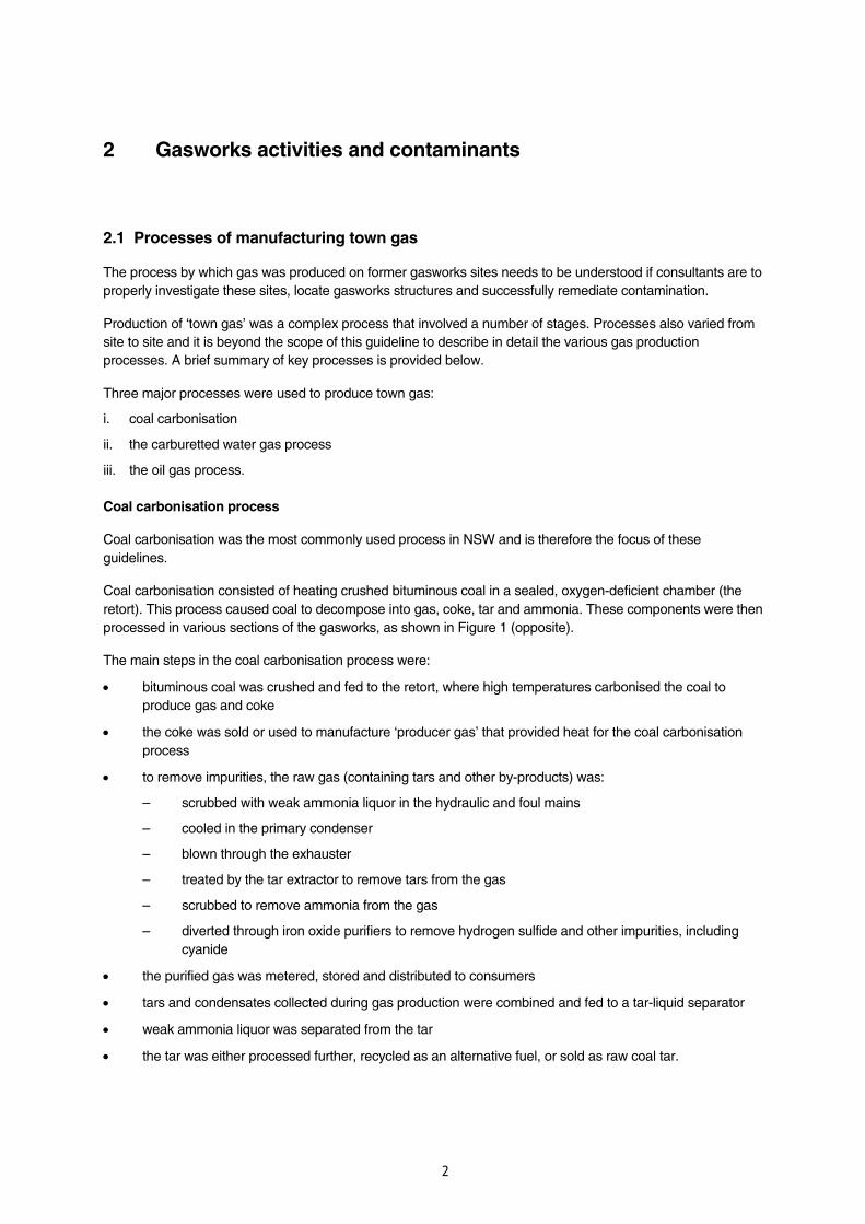
Coal carbonisation process
Coal carbonisation was the most commonly used process in NSW and is therefore the focus of these guidelines.
Coal carbonisation consisted of heating crushed bituminous coal in a sealed, oxygen-deficient chamber (the retort). This process caused coal to decompose into gas, coke, tar and ammonia. These components were then processed in various sections of the gasworks, as shown in Figure 1 (opposite).
The main steps in the coal carbonisation process were:
• bituminous coal was crushed and fed to the retort, where high temperatures carbonised the coal to produce gas and coke
• the coke was sold or used to manufacture ‘producer gas’ that provided heat for the coal carbonisation process
• to remove impurities, the raw gas (containing tars and other by-products) was:
– scrubbed with weak ammonia liquor in the hydraulic and foul mains
– cooled in the primary condenser
– blown through the exhauster
– treated by the tar extractor to remove tars from the gas
– scrubbed to remove ammonia from the gas
– diverted through iron oxide purifiers to remove hydrogen sulfide and other impurities, including cyanide
• the purified gas was metered, stored and distributed to consumers
• tars and condensates collected during gas production were combined and fed to a tar-liquid separator
• weak ammonia liquor was separated from the tar
• the tar was either processed further, recycled as an alternative fuel, or sold as raw coal tar.

Figure 1: Schematic diagram of plant in the coal carbonisation process (from Meade 1934)
Carburetted water gas process and the oil gas process
The carburetted water gas process and the oil gas process produced contaminating by-products that were similar to those associated with the coal carbonisation process — with the exception of ‘lampblack’, a by-product of the oil gas process that is not present at coal carbonisation plants.
Oil shale was also occasionally substituted for coal, resulting in different wastes and contaminants from the coal carbonisation process.
For further information on these processes and associated contaminants, please refer to the Bibliography.
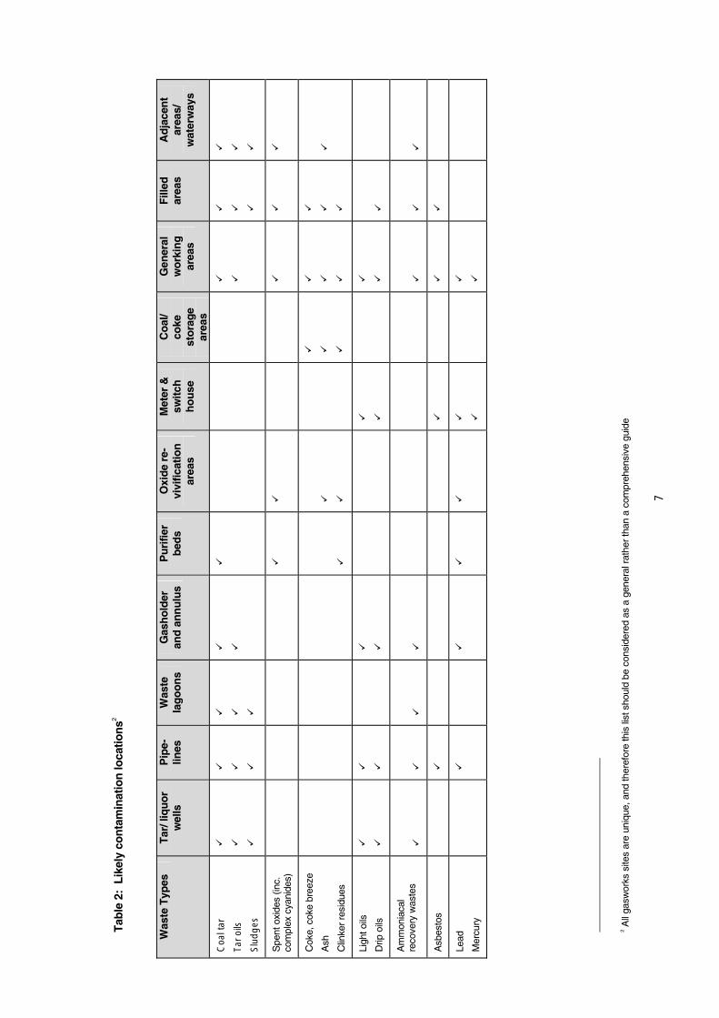
Tables 1 and 2 on pages 6 and 7 summarise the principal features and likely locations of gasworks wastes.
2.2 Wastes and chemicals of interest
2.2.1 Where to expect the major wastes
Major wastes associated with former gasworks sites include tars, oils, hydrocarbon sludges, spent oxide wastes, ash and ammoniacal recovery wastes (see Table 1).
Many of these wastes and by-products were recycled or reused and did not remain on-site. However, it was common for some wastes to be buried or dumped on-site. These wastes may still exist in-situ at the site, for instance in underground tar wells, liquor wells, pipes and purifier beds that were not removed when the gasworks sites were decommissioned.
4
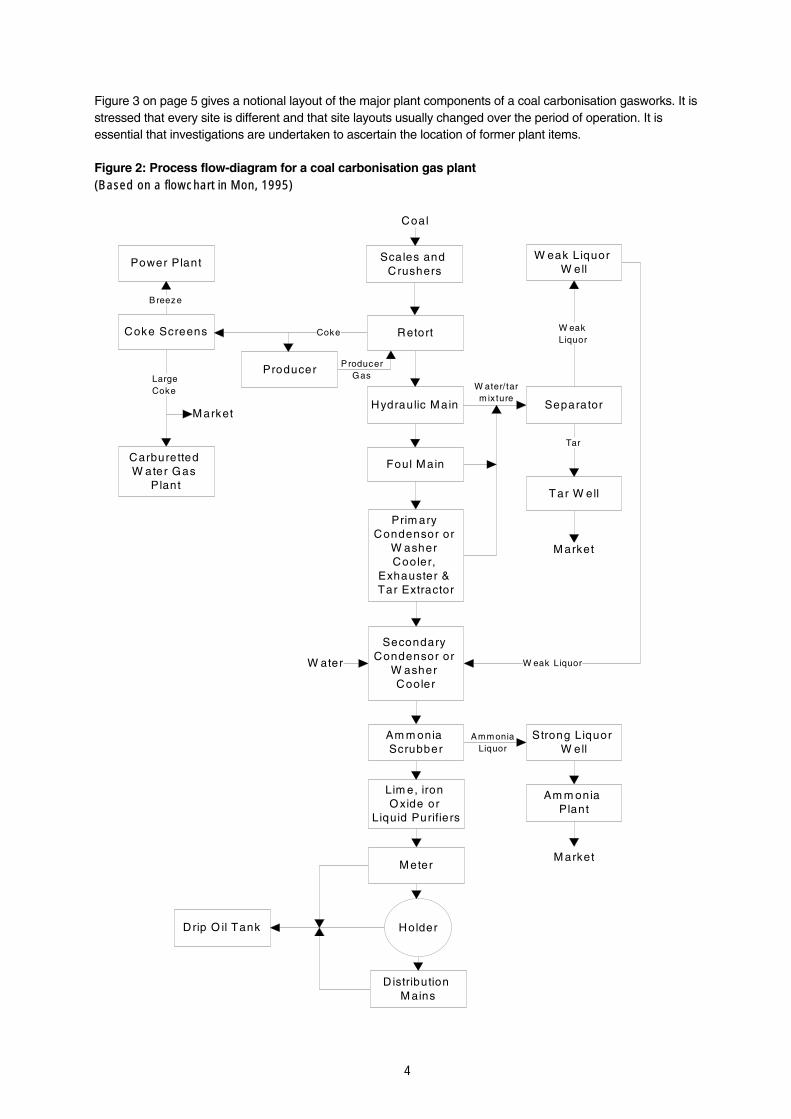
Figure 3 on page 5 gives a notional layout of the major plant components of a coal carbonisation gasworks. It is stressed that every site is different and that site layouts usually changed over the period of operation. It is essential that investigations are undertaken to ascertain the location of former plant items.
Figure 2: Process flow-diagram for a coal carbonisation gas plant (Based on a flowchart in Mon, 1995)
Scales andCrushers
Retort
Hydraulic Main
Foul Main
Prim aryCondensor or
W asherCooler,
Exhauster &Tar Extractor
SecondaryCondensor or
W asherCooler
Am m oniaScrubber
W eak LiquorW ell
Separator
Tar W ell
Coke Screens
Producer
Coal
Power Plant
Lim e, ironOxide or
Liquid Purifiers
Meter
Strong LiquorW ell
Am m oniaPlant
Holder
D istributionM ains
Drip O il Tank
CarburettedW ater Gas
Plant
Market
M arket
Breeze
LargeCoke
Coke
Tar
W eakLiquor
Amm oniaLiquor
W ater
M arket
W eak Liquor
ProducerGas
W ater/tarm ix ture

5
Figure 3: Notional site layout of a coal carbonisation gas plant
Gasworks units that operated under high pressures, such as the retort, may have forced waste by-products up to 15 to 20 metres into the ground or into fissures in the bedrock.
During the operating life of the gasworks, some degree of land contamination is also expected to have occurred from spillage of materials, storage of raw and waste materials and on-site disposal practices.
Wastes may also have been disposed of off-site: in nearby waterways, on railway tracks in neighbouring paddocks, or as part of land reclamation processes.
Further detail on common gasworks wastes is provided in Appendix A.
Retort building (including condensers)
Waste heap
Coke handling
Gas scrubber Purifiers
Coal storage
Gas holder
Tar well in earlier gasholder pit
Tar lagoon
Gas meter
Booster/ Governors
Tar/water separators
Utility building

6
Tab
le 1
: C
har
acte
rist
ics
of p
rin
cip
al g
asw
ork
s w
aste
typ
es
P
rin
cip
al w
aste
typ
e
S
ou
rce
D
istin
gu
ish
ing
ch
arac
teri
stic
s
Lik
ely
chem
ical
gro
up
s
Coa
l tar
Tar
oils
Sep
arat
ed fr
om g
as a
nd li
quor
s at
var
ious
sta
ges
of th
e pu
rific
atio
n pr
oces
ses.
D
ark
brow
n to
bla
ck c
olou
r
Str
ong
phen
olic
odo
ur
Low
er m
eltin
g po
int t
han
petr
oleu
m ta
rs
Diff
eren
t pha
ses
have
low
to h
igh
dens
ity a
nd v
isco
sity
PA
Hs
MA
Hs
Phe
nols
Spe
nt o
xide
s (in
clud
ing
com
plex
cy
anid
es)
Use
d to
rem
ove
sulfu
r du
ring
gas
purif
icat
ion.
S
tron
g su
lfuro
us o
dour
Dis
tinct
ive
Pru
ssia
n bl
ue c
olou
r w
hen
wea
ther
ed/o
xidi
sed
Gre
y/bl
ack/
gree
n, v
ery
dust
y w
hen
not w
eath
ered
/oxi
dise
d
Gra
nula
r ap
pear
ance
Iron
sta
inin
g co
mm
on
Com
plex
cya
nide
s
Fre
e cy
anid
es
Met
als
Cok
e, c
okeb
reez
e (p
owde
r)
Ash
Clin
ker
resi
dues
(gl
assy
mat
eria
l)
By-
prod
ucts
and
furn
ace
resi
dues
. G
ranu
lar
or p
owde
ry te
xtur
e
Ligh
t gre
y to
bla
ck
PA
Hs
Met
als
Ligh
t oils
Drip
oils
Ligh
t oils
use
d ar
ound
all
mac
hine
ry a
nd a
s sc
rubb
ing
agen
t in
reco
very
pro
cess
.
Drip
oils
con
dens
ed fr
om g
as.
Oily
sm
ell a
nd a
ppea
ranc
e M
AH
s
Am
mon
iaca
l rec
over
y w
aste
s N
itrog
en r
emov
al d
urin
g ga
s pu
rific
atio
n pr
oces
ses.
A
mm
onia
cal o
dour
s
Fin
e po
wde
rs o
r sl
udge
s
Phe
nols
Nitr
ates
, sul
fate
s, s
ulfid
es
PA
Hs
Asb
esto
s U
sed
as la
ggin
g ar
ound
man
y of
the
‘hot
’ pr
oces
ses
and
pipe
s.
Fib
rous
to p
owde
ry te
xtur
e
Gre
y-w
hite
/blu
e/gr
eeni
sh c
olou
r (c
ryst
allin
e)
Asb
esto
s
Lead
Mer
cury
Zin
c
Lead
from
bat
terie
s, p
ipel
ines
, pai
nt, e
tc.
Mer
cury
so
met
imes
use
d in
met
erin
g sw
itche
s.
M
etal
s
7
Tab
le 2
: L
ikel
y co
nta
min
atio
n lo
catio
ns2
W
aste
Typ
es
Tar
/ liq
uo
r
wel
ls
Pip
e-
lines
W
aste
la
go
on
s G
ash
old
er
and
an
nu
lus
Pu
rifie
r b
eds
Oxi
de
re-
vivi
ficat
ion
ar
eas
Met
er &
sw
itch
h
ou
se
Co
al/
coke
st
ora
ge
area
s
Gen
eral
w
ork
ing
ar
eas
Fill
ed
area
s A
dja
cen
t ar
eas/
w
ater
way
s
Coa
ltar
Taro
ils
Slu
dg
es
Spe
nt o
xide
s (in
c.
co
mpl
ex c
yani
des)
Cok
e, c
oke
bree
ze
Ash
Clin
ker
resi
dues
Ligh
t oils
Drip
oils
Am
mon
iaca
l
reco
very
was
tes
Asb
esto
s
Lead
Mer
cury
2 All
gasw
orks
site
s ar
e un
ique
, and
ther
efor
e th
is li
st s
houl
d be
con
side
red
as a
gen
eral
rat
her
than
a c
ompr
ehen
sive
gui
de

8
2.2.2 Major contaminants
Major contaminants associated with gasworks wastes are: metals (including metalloids), volatile (or monocyclic) aromatic hydrocarbons, phenolic compounds and polycyclic aromatic hydrocarbons (PAHs) — see Table 3
Natural degradation processes can cause concentrations of some of these chemicals to diminish over time, provided that conditions are suitable. These chemicals may include phenolic compounds, volatile monocyclic aromatic hydrocarbons and some PAHs.
Degradation rates can be extremely slow in the subsurface environment, however, and high concentrations of some contaminants may persist for many years.
Some contaminants are not broken down by biodegradation. For example, heavy metals and complex cyanides will remain in the soil unless they are leached out.
Table 3: Principal chemicals of interest at gasworks sites3
Inorganic Compounds
Metals & Metalloids
Monocyclic Aromatic Hydrocarbons (MAHs)
Phenolics Polycyclic Aromatic Hydrocarbons (PAHs)4
Ammonia
Cyanide
Nitrate
Sulfate
Sulfide
Thiocyanate
Aluminium
Antimony
Arsenic
Barium
Cadmium
Chromium
Copper
Iron
Lead
Manganese
Mercury
Nickel
Selenium
Silver
Vanadium
Zinc
Benzene
Ethyl benzene
Toluene
Total Xylenes
Phenol
2-Methylphenol
4-Methylphenol
2,4-Dimethylphenol
Acenaphthene
Acenaphthylene
Anthracene
Benzo(a)anthracene
Benzo(a)pyrene
Benzo(b)fluoranthene
Benzo(g,h,I)perylene
Benzo(k)fluoranthene
Chrysene
Dibenzo(a,h)anthracene
Fluoranthene
Fluorene
Naphthalene
Phenanthrene
Pyrene
Indeno (1,2,3-cd) pyrene
3 Derived from surveys of gasworks sites in the USA (after Gas Research Institute 1996) and Europe (after Haeseler et al 1999).
4 There are 23 USEPA priority PAHs. In Australia, PAHs are commonly analysed for the above 16 compounds.

9
3 Assessing former gasworks sites
Gasworks are usually very complex sites to assess, due to their long operating history and the variety of organic and inorganic contaminants that were usually spilt, spread or buried around the site.
While these guidelines will assist the process of assessing contamination at gasworks sites — to ensure that the site and its risks to current and future users and the environment are properly managed — it is important to note that each site has unique features that will require assessment by a suitably qualified and experienced consultant.
Assessments should be consistent with processes recommended in the National Environment Protection (Assessment of Site Contamination) Measure (NEPC, 1999).
The EPA’s Guidelines for Consultants Reporting on Contaminated Sites (1997) should also be consulted in preparing a detailed site investigation report on the investigation and remediation of contaminated sites (‘the report’).
3.1 Preliminary investigation before fieldwork
A preliminary site investigation should be performed before consultants begin fieldwork, to describe the condition of the site and to identify all past and present activities and chemicals that hold the potential for contamination. This preliminary assessment of the potential for contamination should be used to determine what further investigations are needed.
Local councils may be able to provide historical information on the location of gasworks site infrastructure.
3.2 Assessing the soil of a former gasworks site
Due to the wide range of operating periods, industrial processes, waste management procedures and circumstances of closure for each gasworks site, it is not possible to prescribe a single protocol for sampling soil components. It is typical, however, for wastes at former gasworks sites to have a highly heterogeneous distribution.
The EPA’s Contaminated Sites: Sampling Design Guidelines (1995) may assist consultants in determining the minimum number of sampling locations required to locate areas of contamination,
based on the estimated size of ‘hot spots’5.
At each sampling location, consultants should collect and analyse soil samples at a minimum of two depths: one in the 0–200 mm surface range; and the other/s according to the maximum depth of disturbance ascertained in the soil profile.
Samples should be analysed for all analytes listed in Table 3, unless close inspection or field screening can confidently rule out a contaminant. This evidence and the rationale for such a decision must be described in the report.
Many of the principal gasworks wastes can be identified visually, such as coal tar, spent oxides and coke breeze (see Table 1). For example, tar oils are easily identifiable as a black, odorous ooze. Iron
5 A hotspot is defined as a discrete localised area where the level of contamination within that area is noticeably greater than in the surrounding areas.

10
cyanide complexes (formed during the removal of hydrogen cyanide) are recognisable by their intense Prussian blue colour.
An appropriate health and safety plan must be implemented to protect on-site workers and public health. Care must be taken during investigation to reduce nuisance to neighbours, particularly by minimising the release of odours (see Section 4.2.2).
3.2.1 If the layout of site infrastructure is known
Where the layout of site infrastructure is known, consultants should use information collected in the preliminary site investigation (in conjunction with information listed in Tables 1 and 2) to devise a site-specific sampling plan.
More detailed guidance on the type of sampling that may be appropriate for specific parts of a gasworks is provided in the Gas Research Institute’s publication Management of Manufactured Gas Plant Sites (1996).
Assessment should initially focus on the location of site infrastructure and process areas, e.g. retort house, tar wells, spent oxide revivifying areas and waste disposal areas. Where the location of these utilities can be reliably estimated — either from the presence of remaining structures or from old photographs and site records — a sampling plan should be designed according to the types of contamination that may be expected in particular locations (refer to Table 3).
As wastes may be buried anywhere on-site, it may be necessary to sample the entire gasworks site for the complete range of potential contaminants.
Test pits or trenches are recommended for more targeted sampling.
3.2.2 If the layout of site infrastructure is not known
If it is not possible to accurately locate specific gasworks process areas, a general soil sampling strategy should be considered.
Where the site layout is not known, the EPA recommends an intrusive soil investigation at a grid spacing no greater than seven metres.
As the distribution of gasworks wastes and contaminants is usually extremely heterogenous, this level of investigation will ensure a high confidence level in finding small but critical subsurface structures, such as underground tar and liquor wells and buried pipelines.
Where gasworks wastes are visually identifiable, it may be possible to limit the number of soil samples that are submitted for laboratory analysis, provided that the rationale for a particular sample not being analysed is stated in the report.
The use of test pits or trenches is recommended for field investigations and geophysical tools may be useful in locating buried structures on-site.
Should the consultant decide to use an alternative sampling strategy, the reason(s) for using the alternative strategy should be fully explained and justified in the report.
3.3 Assessing groundwater at a former gasworks site
The potential for groundwater contamination and off-site migration of contaminants in groundwater must be assessed at all former gasworks sites.
Some gasworks structures can extend to a considerable depth — particularly gas holders and tar pits — and can potentially intercept local aquifers and change local groundwater movement. In most

11
cases, this will require focussed investigations using properly constructed groundwater monitoring bores.
Collection of groundwater from pits is not considered suitable for assessment purposes as it is subject to many potential interferences, including oxygenation and mixing during pit excavation, inflow from the top of the pit, and hydrocarbon contamination from the hydraulics of the back-hoe/excavator bucket.
In simple hydrogeological conditions, at least three monitoring bores are necessary to establish the direction of groundwater flow. It is recommended that these bores are installed away from, but in the vicinity of, areas exhibiting higher levels of soil contamination.
At least one well should be placed upgradient hydraulically and at least two wells downgradient of the most highly contaminated areas.
If groundwater contamination is confirmed downgradient of the affected area(s), the lateral extent of groundwater impact and the extent of off-site migration should be assessed by installing and sampling additional wells in the direction of flow. It may be necessary to install additional wells upgradient of the site as an indicator of ‘background’ water quality.
Groundwater samples should be analysed for all the analytes listed in Table 3, unless close inspection or field screening of the sample enables the presence of a contaminant to be confidently ruled out.
The construction of groundwater monitoring wells must not lead to contamination of underlying aquifers and aquicludes separated by impervious strata from contaminated surface material.
Guidance on construction and use of monitoring bores is provided in Minimum Construction Requirements for Water Bores in Australia (ARMCANZ, 1997). Groundwater bores and monitoring wells may require licensing by the Department of Land and Water Conservation under the Water Management Act 2000.
3.4 Sample chain of custody
The report should include a chain of custody (COC) form(s) filled out by the person/people responsible for each stage of the sampling procedure. A sample COC form is provided in Appendix B. The COC form should be completed and signed on-site by the field staff and the courier, and later by the laboratory staff.
3.5 Analytical methods and chemical analysis
All chemical analyses should be carried out by a laboratory that is currently accredited by the National Association of Testing Authorities (NATA) (or an equivalent organisation) for that particular chemical analysis. As discussed in Section 3.2.2, samples should initially be tested for all potential contaminants (see Table 3), unless it can be demonstrated that specific analytes are not likely to be of concern.
The EPA recommends that laboratories use analytical methodologies specified in NEPC’s Schedule B(3): Guideline on Laboratory Analysis of Potentially Contaminated Soils (1999).
Where no suitable analytical method is provided, the US EPA (1986), American Public Health Association (APHA, 1998), or equivalent analytical procedures, may be used by an accredited laboratory.
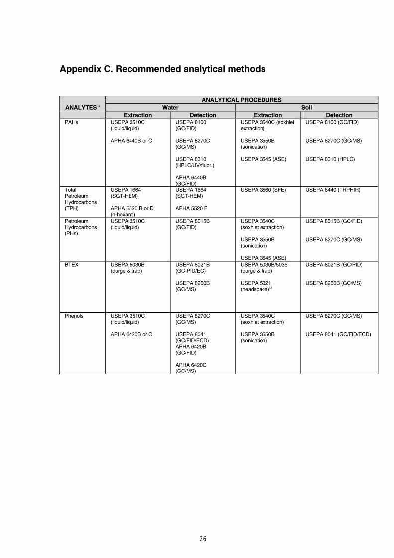
Recommended analytical methods are described in Appendix C.

12
Analytical detection limits, or Practical Quantitation Limits (PQLs), must be consistent with investigation and threshold concentrations. The report should state the PQL for each analyte. Where sample quantitation limits (SQL) are different to the PQL, the SQL should also be quoted.
As some volatile organic compounds (VOCs) may be ‘lost’ to the atmosphere during field sampling and laboratory analysis, it is essential to demonstrate adequate data quality through a data quality assurance and quality control (QA/QC) program (see Schedule B(3), NEPC, 1999). The QA/QC results should include an estimate of VOC losses during sampling.
Two or more separate analyses are required to adequately characterise the range of total petroleum hydrocarbons (TPHs) present (see Schedule B(3) of NEPC (1999) and Appendix C).
3.6 Investigation levels and threshold concentrations
Investigation levels and threshold concentrations for health and environmental protection are included in these guidelines to assist in assessing former gasworks sites (refer to Tables 4 and 5). Where these values are sourced from publications of relevant peak forums — including the Australian & New Zealand Environment & Conservation Council (ANZECC), Agriculture and Resource Management Council of Australia and New Zealand (ARMCANZ), the National Health and Medical Research Council (NHMRC), enHealth and the National Environment Protection Council (NEPC) — the latest edition endorsed under the CLM Act should be referred to.
3.6.1 Soil investigation levels and threshold concentrations
Wherever possible, investigation levels for soils should be selected from Australian sources. These include Schedule B(7) of the National Environment Protection (Assessment of Site Contamination) Measure 1999 (NEPC, 1999) and the Australian and New Zealand Guidelines for the Assessment and Management of Contaminated Sites (ANZECC/NHMRC, 1992).
Soil investigation levels and threshold concentrations of contaminants may be applied directly from the guideline in Tables 4 and 5 if ‘sensitive’ (i.e. residential) land use is proposed. Table 4 also indicates criteria for less sensitive land uses. These investigation levels and the exposure scenarios on which they are based are sourced from the documents referred to above. Threshold concentrations of contaminants are based on an assessment of potential human health and ecological impacts. In some cases, the values for particular criteria may have to be lowered for aesthetic reasons.
Phytotoxicity (i.e. toxicity to plants) of contaminants is used as the indicative environmental effect to be considered in the context of urban redevelopment. The provisional phytotoxicity-based investigation levels (PTLs) proposed in Table 4 are single number criteria. Contaminant concentrations averaged across a site are not applicable for phytotoxicity. These criteria are intended for use as a screening guide. Their use has significant limitations because phytotoxicity depends on soil and species parameters in ways that are not fully understood. If the soil is not sandy loam or in the pH range 6–8, other tests need to be undertaken to determine appropriate phytotoxicity-based investigation levels.
Soil Investigation Levels should be applied in the context of the ‘Decision Process for Assessing Urban Redevelopment Sites’ outlined in the EPA’s Guidelines for the NSW Site Auditor Scheme (1998). The decision process flowchart describes how soil investigation levels should be applied for different land uses.

13
Table 4: Soil investigation levels
Health-based investigation levels a, b (mg/kg)
Column 1 Column 2 Column 3 Column 4 Substance
Residential with gardens/accessible soil (home-grown produce contributing less than 10% fruit and vegetable intake; no poultry) including children’s day care centres, preschools and primary schools
Residential with minimal access to soil including high-rise apartments and flats
Parks, recreational open space, playing fields including secondary schools
Commercial/ industrial
Provisional
phytotoxicity-based
investigation levels c
For sandy loams of pH 6–8 (mg/kg)
Aldrin + dieldrin 10 40 20 50 - Arsenic (total) 100 400 200 500 20 Benzo(a)pyrene h 1 4 2 5 - Beryllium 20 80 40 100 - Boron 3000 12000 6000 15000 - Cadmium 20 80 40 100 3 Chlordane 50 200 100 250 - Chromium (III) d 12% 48% 24% 60% 400 Chromium (VI) 100 400 200 500 1 Cobalt 100 400 200 500 - Copper 1000 4000 2000 5000 100 Cyanides (complex)e 500 2000 1000 2500 - DDT+DDD+DDE 200 800 400 1000 - Heptachlor 10 40 20 50 - Lead 300 1200 600 1500 600 Manganese 1500 6000 3000 7500 500 Methyl mercury 10 40 20 50 - Mercury (inorganic) 15 60 30 75 1 f Nickel 600 2400 600 3000 60 PAHs (total) g, h 20 80 40 100 - PCBs (total) 10 40 20 50 - Phenol 8500 34000 17000 42500 70 Zinc 7000 28000 14000 35000 200 Petroleum hydrocarbon components: h >C16-C35 aromatics 90 360 180 450 - >C16-C35 aliphatics 5600 22400 11200 28000 - >C35 aliphatics 56000 224000 112000 280000 -
Notes to Table 4
(a) The limitations of health-based soil investigation levels are discussed in the National Environment Protection (Assessment of Site Contamination) Measure 1999 (NEPC, 1999).
(b) Odours may occur at these concentrations
(c) The provisional phytotoxicity-based investigation levels proposed in this document are single number criteria. Their use has significant limitations as phytotoxicity depends on soil and species parameters in ways that are not fully understood. Phytotoxicity-Based Investigation Levels, intended for use as screening guidance, may be assumed to apply to sandy loam soil, or soils of a closely similar texture, and at a pH of between 6 and 8.
(d) Soil discolouration may occur at these concentrations.
(e) See discussion in the National Environment Protection (Assessment of Site Contamination) Measure 1999 (NEPC, 1999). To use the health investigation level for complex cyanides, no more than 5% of free cyanides should be present, with the converse applying for free cyanides.
(f) Total Mercury
(g) PAHs-Polycyclic Aromatic Hydrocarbons
(h) See discussion in the National Environment Protection (Assessment of Site Contamination) Measure 1999 (NEPC, 1999). If indicator chemicals are not found to be present then TPH fractions should be assessed. For other fractions or where it is not possible to confidently distinguish between these components, the threshold concentrations in Table 5 should be used, without multiplication for different exposure scenarios.
14
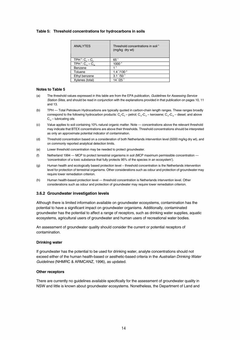
Table 5: Threshold concentrations for hydrocarbons in soils
ANALYTES
Threshold concentrations in soil a (mg/kg dry wt)
TPH b: C6 – C9 65 c TPH b: C10 – C36 1000 d Benzene 1 e Toluene 1.4 f /130 g Ethyl benzene 3.1 f /50 h Xylenes (total) 14 f /25 h
Notes to Table 5
(a) The threshold values expressed in this table are from the EPA publication, Guidelines for Assessing Service Station Sites, and should be read in conjunction with the explanations provided in that publication on pages 10, 11 and 13.
(b) TPH — Total Petroleum Hydrocarbons are typically quoted in carbon-chain length ranges. These ranges broadly correspond to the following hydrocarbon products: C6-C9 – petrol; C10-C14 – kerosene; C12-C18 – diesel; and above C18 – lubricating oils
(c) Value applies to soil containing 10% natural organic matter. Note — concentrations above the relevant threshold may indicate that BTEX concentrations are above their thresholds. Threshold concentrations should be interpreted as only an approximate potential indicator of contamination.
(d) Threshold concentration based on a consideration of both Netherlands intervention level (5000 mg/kg dry wt), and on commonly reported analytical detection limits.
(e) Lower threshold concentration may be needed to protect groundwater.
(f) Netherland 1994 — MCP to protect terrestrial organisms in soil (MCP maximum permissible concentration —‘concentration of a toxic substance that fully protects 95% of the species in an ecosystem’).
(g) Human health and ecologically based protection level – threshold concentration is the Netherlands intervention level for protection of terrestrial organisms. Other considerations such as odour and protection of groundwater may require lower remediation criterion.
(h) Human health-based protection level — threshold concentration is Netherlands intervention level. Other considerations such as odour and protection of groundwater may require lower remediation criterion.
3.6.2 Groundwater investigation levels
Although there is limited information available on groundwater ecosystems, contamination has the potential to have a significant impact on groundwater organisms. Additionally, contaminated groundwater has the potential to affect a range of receptors, such as drinking water supplies, aquatic ecosystems, agricultural users of groundwater and human users of recreational water bodies.
An assessment of groundwater quality should consider the current or potential receptors of contamination.
Drinking water
If groundwater has the potential to be used for drinking water, analyte concentrations should not exceed either of the human health-based or aesthetic-based criteria in the Australian Drinking Water Guidelines (NHMRC & ARMCANZ, 1996), as updated.
Other receptors
There are currently no guidelines available specifically for the assessment of groundwater quality in NSW and little is known about groundwater ecosystems. Nonetheless, the Department of Land and

15
Water Conservation’s (DLWC’s) State Groundwater Policy Framework6 emphasises that, where
scientific knowledge is lacking, the precautionary principle should be applied to protect groundwater.
In the absence of specific criteria for the assessment of groundwater contamination, the Australian and New Zealand Guidelines for Fresh and Marine Water Quality (ANZECC & ARMCANZ 2000) are commonly used as interim assessment criteria. The ANZECC & ARMCANZ 2000 guidelines are derived from available ecosystem toxicity data, indicating contaminant concentrations which, if not exceeded, indicate that there will be no significant impact on the relevant receptor(s). The guidelines are part of the National Water Quality Management Strategy and, strictly speaking, apply to the protection of aquatic ecosystems for surface waters rather than to groundwater directly. However, in many areas of NSW, groundwater is intrinsically linked with surface water and the use of these guidelines as assessment criteria for groundwater is considered to be consistent with DLWC’s recommendation of a precautionary approach.
It is noted that criteria in the ANZECC & ARMCANZ 2000 guidelines for volatile compounds may not be conservative enough for groundwater, given that volatilisation potential in groundwater is limited compared with surface waters and that potential human exposure pathways also need to be considered.
Alternatively, the ANZECC & ARMCANZ 2000 guidelines describe a methodology for deriving site-specific assessment criteria. This is a complex process, and where it is proposed to derive site-specific criteria it is necessary to ensure appropriate expertise contributes to the process (for instance, expertise in ecotoxicology).
The ANZECC & ARMCANZ 2000 guidelines should be used in conjunction with the NSW Government’s Water Quality and River Flow Interim Environmental Objectives. These documents set out the water quality management objectives for 31 catchments in NSW, and must be taken into account when assessing potential impacts on water quality (surface waters).
Users should refer to the ANZECC & ARMCANZ 2000 guidelines for more detailed advice on how the trigger levels should be applied. In practice, it is appropriate to apply the 95% species protection levels for aquatic ecosystems in slightly to moderately-disturbed ecosystems (most urban catchments) and the 99% species protection levels in pristine or vulnerable ecosystems or where the contaminants are intractable (for example, bioaccumulative).
To incorporate the combined toxicities of chemical mixtures into an assessment of water quality, refer to section 8.3.5.18 of the ANZECC & ARMCANZ 2000 guidelines. Where criteria for a particular contaminant is not available in ANZECC & ARMCANZ 2000 guidelines, they provide decision frameworks for assessing test data and deriving site-specific water quality criteria.
A summary of appropriate threshold levels for drinking waters and investigation trigger levels for aquatic ecosystems is provided in Table 6. The table is a summary only, and not intended to supersede the original guideline documents referred to above.
6 The NSW State Groundwater Policy Framework Document was released by DLWC in 1997 and outlines general principles for managing the State’s groundwater resources within the context of ecologically sustainable development. Since then, DLWC have developed a series of groundwater policy documents which fall under the State Groundwater Policy Framework. For reference, these are listed in the bibliography.

16
Table 6: Threshold concentrations for water
TOXICANTS IN WATER Trigger values for aquatic ecosystems b (:g/L)
Freshwater Marine
Protection of drinking water a
(:g/L)
Level of protection (% species) Level of protection (% species)
ANALYTES
Health Aesthetic 99% 95% 99% 95% TPH: C6 – C9
c - d - d - d - d - d - d TPH: C10 – C36
c - d - d - e - e - e - e Benzene < 1 f 600 950 500 700 Toluene 800 25 - g 180 h - g 180 h Ethyl benzene 300 3 - g 80 k - g 5 h Xylenes (total) 600 20 - g - g - g - g Ortho-xylenes 200 350 - g 350 h Meta-xylenes - g 75 h - g 75 h Para-xylenes 140 200 - g 200 h Anthracene - g 0.01 h 0.4 h, k 0.01 h 0.4 h, k Benzo(a)pyrene 0.01 0.1 h 2 h, k 0.1 h 2 h, k Fluoranthene - g 1 h 1.4 h, k 1 h 1.4 h, k Naphthalene - g 2.5 16 50 70 Phenanthrene - g 0.6 h 2 h, k 0.6 h 2 h, k Total PAHs - g Phenol 85 320 270 400 Antimony (as Sb(III)) 3 - g 9 h - g 270 h, m Arsenic (total) 7 as As(III) 1 24 - g 2.3 h as As(V) 0.8 13 - g 4.5 h Cadmium n 2 0.06 0.2 0.7 5.5 Chromium (Cr III) n - h - g 3.3 h 7.7 27.4 Chromium (Cr IV) n 50 p 0.01 1.0 0.14 4.4 Copper n 2000 1000 1.0 1.4 0.3 1.3 q Lead n 10 1.0 3.4 2.2 4.4 Mercury (total) r 1 Mercury (inorganic) 0.06 0.6 0.1 0.4 Mercury (methyl) - g - g - g - g Nickel n 20 8 11 7 70 Zinc n - s 3000 2.4 8 7 15 Cyanide 80 Free cyanide t 4 7 2 4 Sulfate 500mg/L 250mg/L
Sulfide - u Hydrogen sulfide - u 50 0.5 1 - g 1 h Ammonia - s 500 320 900 v 500 910 h Nitrate 50mg/L 17 700 - g 700 h
Nitrite 3000
Shaded areas identify trigger values applying to typical slightly-moderately disturbed systems; see Table 3.4.2 and Section 3.4.2.4 of the ANZECC & ARMCANZ (2000) guidelines for guidance on applying these levels to different ecosystem conditions.
Notes to Table 6
(a) Guideline values are taken from the Australian Drinking Water Guidelines (NHMRC/ARMCANZ, 1996 and updates).
(b) Guideline values are taken from the Australian and New Zealand Guidelines for Fresh and Marine Water Quality (ANZECC & ARMCANZ, 2000). The latest endorsed edition of that publication should be referred to for updated values.
(c) Some hydrocarbon values are being investigated under the NEPC process. These should be used in the event that they are endorsed by the NSW EPA under the CLM Act.
(d) Information needed to select threshold concentrations is incomplete. Alkanes in this range have low solubility and are unlikely to be of concern in water. All separate phase (i.e. undissolved) products must be removed.

17
(e) The ranges cited in Table 8.3.24 of the ANZECC & ARMCANZ (2000) guidelines can be used if there are no data on the specific oil in question. The trigger value (low reliability) can be calculated by applying an assessment factor of 100 to the lowest acute figure in the appropriate range.
(f) No safe concentration of benzene in drinking water can be set with confidence. For practical purposes the concentration should be less than 1 :g/L, which is the limit of determination.
(g) Information needed to determine trigger values is incomplete.
(h) Low-reliability figure. Should only be used as an indicative interim working level. It is expected that the low-reliability levels are conservative, and the decision scheme outlined in the ANZECC & ARMCANZ (2000) guidelines may help to determine if local factors may increase or decrease the environmental risk.
(k) The 99% protection level is recommended if no data are available on bioaccumulation effects at specific sites.
(m) Caution is advised if the freshwater figure for antimony is exceeded, because of the more limited marine data available.
(n) Aquatic ecosystem trigger values are hardness-dependent for freshwater ecosystems. Trigger values presented here are standardised to a water hardness of 30 mg/L CaCO3. For waters of different hardness, site-specific trigger values should be calculated using the algorithms provided in Table 3.4.3 of the ANZECC & ARMCANZ (2000) guidelines.
(p) The concentration of hexavalent chromium in drinking water should not exceed 50 :g/L. If the concentration of total chromium exceeds this value then a separate analysis for hexavalent chromium should be undertaken.
(q) Trigger value is above a known chronic No Observed Effect Concentration (NOEC) for one or more species.
(r) Total mercury includes inorganic and organic mercury.
(s) No health-based guideline is proposed.
(t) Cyanide as un-ionised HCN, measured as [CN-]. See Section 8.3.7.2 of the ANZECC & ARMCANZ (2000) guidelines.
(u) No health-based guideline has been set for hydrogen sulfide, or sulfide, as the aesthetic guideline is considerably below the concentration that would cause health problems.
(v) As total Ammonia-N. The guideline is pH dependent; Table 8.3.7 in the ANZECC & ARMCANZ (2000) guidelines indicates how the guideline figure changes at different pH levels.
Separate phase product
‘Separate phase product’ is defined as immiscible liquid-phase hydrocarbon existing in the subsurface of the soil with a positive pressure such that it can flow into a monitoring well. Several known gasworks contaminants may exist as separate phase product, both LNAPL (Light Non-Aqueous Phase Liquids) and DNAPL (Dense Non-Aqueous Phase Liquids).
All identified separate phase products must be removed from the substrate as far as possible, since it presents an ongoing source of groundwater contamination and potential explosive hazard.

18
4 Remediating former gasworks sites
Remediation of former gasworks sites is complicated by the presence of mixed organic and inorganic contaminants commonly found in the soil and groundwater around the sites. Remediation operations must not result in adverse impacts on the environment or human health, including air quality, water quality, noise levels and waste management.
All work on-site must take into account the various provisions of environmental and occupational health and safety legislation. The EPA’s Guidelines for Consultants Reporting on Contaminated Sites (1997) and Guidelines for the NSW Site Auditor Scheme (1998) provide guidance on issues relevant to former gasworks sites, including the development of a remedial action plan and validation strategy.
4.1 Remediation options
The preferred hierarchy of options for site clean up and management is:
• on-site treatment of the contamination so that it is destroyed or the associated risk is reduced to an acceptable level, and
• off-site treatment of excavated soil, so that the contamination is either destroyed or the associated risk is reduced to an acceptable level, after which it is returned to the site.
If neither of these options can be implemented, consider the following:
• removal of contaminated material to an approved site or facility — refer to the EPA’s Environmental Guidelines: Assessment, Classification and Management of Liquid & Non-Liquid Wastes (1999) — and replacement, where necessary, with validated clean fill, or
• consolidation and isolation of the soil on-site by containment with a properly designed barrier (this option will require the development and implementation of a site management plan with appropriate approvals and regulation from the EPA and/or relevant planning authority, and may also require ongoing monitoring to ensure the integrity of the barrier/containment cell).
Where the assessment indicates that remediation would have no net environmental benefit – or a net adverse environmental effect — an appropriate management strategy must be implemented to address the contamination.
Future land use of the site may be restricted, depending on the nature and extent of remediation at the site.
4.2 Control of site emissions
In-situ treatment processes should be used wherever possible to prevent emission of pollutants to the environment. Where they cannot be used, ex-situ systems that prevent emissions should be used, where practicable, such as enclosed bioremediation cells built elsewhere on-site (or off-site) with exhaust gas treatment and leachate controls.
4.2.1 Air pollutants
Air pollutants of potential concern include VOCs, polycyclic aromatic hydrocarbons, sulfur compounds, hydrogen cyanide and dust. All these compounds should be monitored on-site and off-site. If there are high concentrations of VOCs present and the soil must be excavated, the soil may first need to be vented and the gas/odour emissions controlled.

19
During any excavation work, the consultant supervising a site remediation process should use work practices that minimise the impact of dust emissions (e.g. use water sprays, minimise exposed workfaces) and take local weather conditions into account.
4.2.2 Odours
No offensive odours should be detectable beyond the site boundary. While the potential for odour complaints depends, of course, on how close the gasworks site is to the local community, VOCs, semi-volatiles and sulfur compounds can be detected by smell at concentrations of parts per billion or lower.
Provision should be made for allowing any affected members of the community to report odours that arise during the remediation activities and for these reports to be logged and, if necessary, acted upon.
If odours are identified as a problem, appropriate mitigation measures must be implemented. Potential measures can include the covering of odour sources, minimising exposure of sources and use of suppressant or neutralising agents. Local microclimate studies may be necessary to ascertain how and when odours are dispersed to nearby areas.
Odour mitigation practices should be periodically audited on an area-by-area basis and if complaints continue, further mitigation measures should be considered.
Persistent odour problems may necessitate more intensive odour prevention measures, such as pretreatment of source areas before disturbance, tenting, microclimate control and fully compensated relocation of affected residents during the remediation activities.
4.2.3 Site run-off
Substances that are disturbed during remediation works can easily pollute local surface waters and groundwaters. All run-off from the site should therefore be collected and managed appropriately until the site has been successfully remediated and the remediation has been validated.
4.3 Community consultation
It is important to consider the need for community consultation prior to, and during, remediation of former gasworks sites. Where the community may be affected by assessment or remediation, measures should be implemented to keep the community informed of assessment/remediation progress, as well as measures taken to prevent/minimise disturbance beyond the remediation area.

20
5 Validating former gasworks sites
Validation sampling and chemical analyses must be carried out to demonstrate that the site has been remediated to a standard that is suitable for the proposed land use and that residual contamination will not be harmful to human health or the environment. The strategy and results of a successful remediation and validation should be contained in a Validation Report.
A systematic sampling pattern is recommended for the validation sampling plan. The data obtained from the validation program should be statistically analysed.
For a former gasworks site to be validated, the 95% upper confidence limit (UCL) on the average concentration for each analyte should be below the relevant threshold concentration. Where the 95% UCL is less than the relevant threshold value but one or more individual sample measurements are more than 25% above the criteria, any sampling point which exceeds this level should be re-investigated to determine whether or not it constitutes a ‘hot spot’.
Further information on appropriate sampling densities and statistical analysis of validation programs may be found in the EPA’s Sampling Design Guidelines (1995), in NEPC’s Schedule B(2): Data Collection, Sample Design and Reporting (1999) and the USEPA’s Method for Evaluation of the Attainment of Cleanup Standards (1989).
Validation sampling and analysis requires rigorous field and laboratory QA/QC. Field screening techniques such as photo-ionisation detectors should be comprehensively validated or avoided, and only the recommended methods should be employed for sample analysis (Schedule B(3),NEPC (1999)).

21
6 Reporting
All site assessment reports, remedial action plans and validation reports should conform to the EPA’s Guidelines for Consultants Reporting on Contaminated Sites (1997).

22
Appendix A. Major contaminants and where to expect them
Information on contaminants and where they can be located, additional to the information in Table 2, is outlined below:
(a) Coal tar
A range of tars are associated with gasworks, from tars slightly more dense and viscous than water to those that were solid at ambient temperature and required heating before they could flow. Coal tars contained principally aromatic hydrocarbons, e.g. benzene, naphthalene, anthracene and related compounds; tar acids (phenolics); and tar bases (nitrogen-containing organics) — refer Table 1. Raw coal tar also contained a small amount of light oils (approximately 2%) which were dissolved in the heavier tar layer.
Coal tars may be found in the following areas:
• underground tar and liquor wells
• purifier beds (spent oxide)
• reprocessing area (if present)
• general surface areas around tar wells and over site
• buried pipes, lagoons or pits
• nearby railway track or stream
• buried on site and in reclaimed area (ie if adjacent to waterway).
(b) Light oils
Light oils would not have been disposed of as waste, but leakage and spills of scrubbing oils from the recovery process or distilled light oils could create local areas of contamination. Light oils are composed principally of light monocyclic aromatic hydrocarbons (e.g. benzenes, toluenes, ethyl benzenes and xylenes), alkanes and alkenes (e.g. petroleum hydrocarbons). Substitution of oil shale for coal in processes may increase the levels of such substances present.
(c) Drip oils
Drip oils were any hydrocarbons that condensed as a liquid in the gas holder, gas meter or in mains when the gas cooled to ambient temperatures. The drip oil was collected in underground tanks at the low end of the gas mains.
The drip oils were not considered wastes as they could be added to either the raw tar or light oils. The tanks may remain at the plant and may have leaked, contaminating soil underground.
(d) Waste sludges
Water purification sludges resulted from a method used to purify waste condensate. At many plants, the aqueous waste stream was treated with lime or soda ash and copper prior to discharge. The solids in the waste coagulated as small particles and settled as a sludge comprising about 10% solids and 90% oil and water. This sludge could be mixed with the coke and burned in the plant's boilers, or disposed of at or near the gas production site.

23
Acid sludge from light oil agitators resulted from either the distillation of tar or scrubbing the gas, which commonly was treated with sulfuric acid to remove the basic compounds and improve its quality. The waste was burnt on-site in trenches. However, only a portion would burn and the remainder would be very acidic. The base nitrogen compounds in the light oils would generally be extracted into the waste and disposed with it.
(e) Ammoniacal recovery wastes
When ammonia stills were used to release fixed ammonia salts, ammonia still waste was produced. The ammonia still waste was first treated for the removal of phenols by discharging into baffled sumps where solid matter settled out and liquid cooled. Accumulations of sediment (lime settlings) were removed and usually disposed of to local landfills.
(f) Hydrogen sulfide removal wastes (spent oxides)
Along with coal tar, spent oxide is one of the major wastes remaining on coal carbonisation plant sites. Spent oxides were usually disposed of at the local landfill, or used as fill around the plant or on private property. Spent oxide wastes contain tar, some volatile organics, iron oxide, Fe2S3, FeS, FeS2, sulphur (45-60%), fluff materials (usually woodchips), ferric ferrocyanide (Prussian blue) Fe4[Fe(CN)6]3 and thiocyanates (refer Table 2).
Spent oxide wastes undergo some degradation after disposal. The FeS oxidises to form sulfuric acid, which helps to further oxidise and dissolve the remaining iron oxides in the waste. Depending on the amount of tar in the waste, the woodchips may or may not be broken down by the acid. However, the highly acidic conditions do not appear to decompose the ferric-ferrocyanide compounds. When the iron oxides dissolve away, the ferric-ferrocyanide compounds become small unattached particles that can migrate short distances from the waste to stain wood, rocks, soil and other materials not originally present in the spent oxide.
An analysis of disposed spent oxide wastes in Massachusetts, USA, revealed the following constituents (Harkins et al. 1988):
• pH 1.7-3.8
• Total cyanide 7,500 mg/kg
• Water-soluble cyanide 0.7 mg/kg
PAH compounds (mg/kg dry weight)
• naphthalene 0.83
• benzo(a)anthracene 1.7
• benzo(a)pyrene 2.1
• benzo(b)fluoranthene 5.1
• benzo(k)fluoranthene 2.2
• chrysene 1.6
• benzo(ghi)perylene 2.0
• ideno(1,2,3-cd)pyrene 2.0
• pyrene 2.8
• fluoranthene 6.1
• bi-(2-ethylhexyl)phthalate 1.7

24
(g) Ash, clinker and coke
Ash, slag and coke (80% carbon) were by-products of town gas production. Leachable metals may be associated with ash and slag, but only limited information about its constituents is available.
The ash was produced from boilers and producer gas generators. It was usually used for fill and grading purposes. The amount of ash produced by gas manufacturers was directly proportional to the ash content of the coals and coke used for gas production. The coke is generally considered to be inert.

Appendix B. Chain of custody form
26
Appendix C. Recommended analytical methods
ANALYTICAL PROCEDURES ANALYTES a Water Soil
Extraction Detection Extraction Detection PAHs USEPA 3510C
(liquid/liquid) APHA 6440B or C
USEPA 8100 (GC/FID) USEPA 8270C (GC/MS) USEPA 8310 (HPLC/UV/fluor.) APHA 6440B (GC/FID)
USEPA 3540C (soxhlet extraction) USEPA 3550B (sonication) USEPA 3545 (ASE)
USEPA 8100 (GC/FID) USEPA 8270C (GC/MS) USEPA 8310 (HPLC)
Total Petroleum Hydrocarbons (TPH)
USEPA 1664 (SGT-HEM) APHA 5520 B or D (n-hexane)
USEPA 1664 (SGT-HEM) APHA 5520 F
USEPA 3560 (SFE) USEPA 8440 (TRPHIR)
Petroleum Hydrocarbons (PHs)
USEPA 3510C (liquid/liquid)
USEPA 8015B (GC/FID)
USEPA 3540C (soxhlet extraction) USEPA 3550B (sonication) USEPA 3545 (ASE)
USEPA 8015B (GC/FID) USEPA 8270C (GC/MS)
BTEX USEPA 5030B (purge & trap)
USEPA 8021B (GC-PID/EC) USEPA 8260B (GC/MS)
USEPA 5030B/5035 (purge & trap) USEPA 5021 (headspace)(b)
USEPA 8021B (GC/PID) USEPA 8260B (GC/MS)
Phenols USEPA 3510C (liquid/liquid) APHA 6420B or C
USEPA 8270C (GC/MS) USEPA 8041 (GC/FID/ECD) APHA 6420B (GC/FID) APHA 6420C (GC/MS)
USEPA 3540C (soxhlet extraction) USEPA 3550B (sonication)
USEPA 8270C (GC/MS) USEPA 8041 (GC/FID/ECD)

27
ANALYTICAL PROCEDURES
ANALYTES a Water Soil Extraction Detection Extraction Detection
Antimony Arsenic Cadmium Copper Lead Zinc Nickel Tin Chromium
APHA 3030E USEPA 3010A (Flame AAS or ICP) USEPA 3020A (ET-AAS)
APHA 3111 (Flame AAS) APHA 3120 (ICP-AES) USEPA 200.7 (ICP-AES) USEPA 200.8 (ICP-MS) APHA 3125 (ICP-MS) APHA 3113 (ET-AAS) USEPA 200.9 (ET-AAS) USEPA 6010B USEPA 6020A
USEPA 3050B/3051 APHA 3111 (Flame AAS) APHA 3120 (ICP-AES) USEPA 200.7 (ICP-AES) USEPA 200.8 (ICP-MS) APHA 3125 (ICP-MS) APHA 3113 (ET-AAS) USEPA 200.9 (ET-AAS) USEPA 6010B USEPA 6020A
Mercury USEPA 7470A APHA 3112
USEPA 7470A APHA 3112 (Cold Vapour AAS)
USEPA 7471A USEPA 7470 USEPA 7471A APHA 3112 (Cold Vapour AAS)
Free cyanide USEPA 9014 ASTM D 4282-95
USEPA 9014 ASTM D 4282-95
Total cyanide APHA 4500-CN- B followed by 4500-CN-C USEPA 9010B or 9012A
APHA 4500-CN- D or E or F
USEPA 9010B or 9012A
USEPA 9013/USEPA 9010
USEPA 9013/USEPA 9010
Cyanides amenable to chlorination Weak Acid Dissociable Cyanide
APHA 4500-CN- B followed by 4500-CN-G USEPA 9010B or 9012A APHA 4500-CN- B followed by 4500-CN-I
APHA 4500-CN- D or E or F USEPA 9010B or 9012A APHA 4500-CN- D or E or F
USEPA 9013/USEPA 9010
USEPA 9013/USEPA 9010
Sulfate Discrete sample preparation method is not required
APHA 4500 SO4 USEPA 9035, 9036, 9038
B(3) NEPC (1999) Method 406
APHA 4500 SO4 USEPA 9035, 9036, 9038
Sulfide APHA 4500 S USEPA9030B
APHA 4500 S USEPA9034 USEPA 9215
USEPA 9031 USEPA 9031 APHA 4500 S
Later editions or other appropriate United States Environmental Protection Agency (USEPA) and/or American Public Health Association (APHA) methods may be used, but if alternative methods to those recommended are used, then the consultant should provide evidence that the selected methods perform as well as those recommended, substantiated by appropriate QA/QC measures.
(a) Detection limits, where possible, should be selected so as to meet the appropriate criteria.
(b) Headspace may not be suitable for soils due to the low sensitivity of this technique. The applicable concentration range using USEPA method 5021 is from 10 to 200µg/kg. Closed system purge and trap may be required.
Where there is some interference with FID for the analysis of PAHs and phenols, a more selective detector such as MS should be used.

28
Bibliography
American Public Health Association (APHA) Clesceri L S, Greenberg A E and Eaton A D (eds), Standard Methods for the Examination of Water and Wastewater, 20th Edition, APHA, American Water Works Association & The Water Environment Federation, New York, 1998.
ANZECC (Australian and New Zealand Environment and Conservation Council) and NHMRC (National Health and Medical Research Council), Australian and New Zealand Guidelines for the Assessment and Management of Contaminated Sites, Canberra, January 1992.
ANZECC, Australian Water Quality Guidelines for Fresh and Marine Waters, Canberra, November 1992.
ANZECC & ARMCANZ (Agriculture and Resource Management Council of Australia and New Zealand), Australian and New Zealand Guidelines for Fresh and Marine Water Quality, Canberra, 2000.
ARMCANZ and NHMRC, National Water Quality Management Strategy: Australian Drinking Water Guidelines, Canberra, 1996.
ARMCANZ, Minimum Construction Requirements for Water Bores in Australia, Canberra, 1997.
Department of the Environment (UK), Problems Arising from the Redevelopment of Gas Works and Similar Sites (Second Edition), prepared by Environmental Resources Limited, Her Majesty's Stationery Office, London, 1987.
Department of Land and Water Conservation (DLWC), The NSW State Groundwater Policy Framework Document, NSW, August 1997.
DLWC, The NSW State Groundwater Quality Protection Policy, NSW, Dec 1998.
DLWC, The NSW State Groundwater Dependent Ecosystems Policy, NSW, Apr 2002.
Edwards J W, Van Alpen M and Langley A, Identification and Assessment of Contaminated Land: Improving Site History Appraisal, South Australian Health Commission, Adelaide,1994.
Haesler F, Blanchet D, Druelle V, Werner P, & Van de Casteele J P, ‘Analytical Characterisation of Contaminated Soils from Former Manufactured Gas Plants’, pp 825–830 in Environmental Science & Technology 33(6), American Chemical Society, Washington, 1999.
Gas Research Institute (GRI), Management of Manufactured Gas Plant Sites: The Gas Research Institute’s Two Volume Practical Reference Guide, Volumes I & 2 GRI-96/0470.1 & GRI-96/0470.2, GRI, Chicago, 1996.
Harkins S, Truesdale R, Hill R, Hoffman P, Winters S, US Production of Manufactured gases: assessment of past disposal practices, Hazardous Waste Engineering Research Laboratory, US Environmental Protection Agency, Cincinnati, 1988.
Interdepartmental Committee on the Redevelopment of Contaminated Land, Notes on the Redevelopment of Gasworks Sites, (5th ed), United Kingdom Department of the Environment, Middlesex, 1986.
Meade A, New Modern Gasworks Practice, Vol 1, Eyre and Spottiswoode, London, (in UK Atomic Energy Authority, Harwell, 1981), 1934.
29
Middleton A, ‘Historical Overview of Manufactured Gas Plant Processes Used in the United States’ pp 5–17 to 5–19, in Land Contamination & Reclamation, 3(4), EPP Publications, Richmond, Surrey, 1995.
Ministry of Housing, Spatial Planning and the Environment, Environmental Quality Objectives and their Policy Framework in the Netherlands, Risk Assessment and Environmental Quality Division, Directorate for Chemicals, External Safety and Radiation Protection, Netherlands Ministry of Housing, Spatial Planning and the Environment, The Hague, 1994.
Mon G J, ‘History of the Manufactured Gas Business in the United States’, pp 1–1 to 1–3, in Land Contamination & Reclamation, 3(4), EPP Publications, Richmond, Surrey, 1995.
Murray–Darling Basin Commission (MDBC), Murray–Darling Basin Groundwater Sampling Guidelines, Technical Report No. 3, Groundwater Working Group, [Canberra], August 1997.
NEPC (National Environment Protection Council) National Environment Protection (Assessment of Site Contamination) Measure, NEPC Service Corporation, Adelaide, 1999.
NSW Department of Urban Affairs and Planning, State Environmental Planning Policy No. 55 — Remediation of Land, Sydney 1998.
NSW Department of Urban Affairs and Planning and NSW EPA (Environment Protection Authority NSW), Managing Land Contamination: Planning Guidelines, Sydney, 1998.
NSW EPA (Environment Protection Authority NSW), Guidelines for Assessing Service Station Sites, Sydney, 1994.
NSW EPA (Environment Protection Authority NSW), Sampling Design Guidelines for Contaminated Sites, Sydney, 1995.
NSW EPA (Environment Protection Authority NSW), Guidelines for Consultants Reporting on Contaminated Sites, Sydney, 1997.
NSW EPA (Environment Protection Authority NSW), Environmental Guidelines: Assessment, Classification and Management of Liquid and Non-Liquid Wastes, Sydney, 1999.
NSW EPA (Environment Protection Authority NSW), Guidelines on Significant Risk of Harm from Contaminated Land and the Duty to Report, Sydney, 1999.
Turczynowicz L, ‘The Assessment and Management of Gasworks Sites’, in The Health Risk Assessment and Management of Contaminated Sites: Contaminated Sites Monograph Series No. 2, South Australian Health Commission, Adelaide, 1993.
United Kingdom Atomic Energy Authority, Harwell, Problems Arising from the Redevelopment of Gas Works and Similar Sites, Her Majesty’s Stationery Office, Oxfordshire, November 1981.
USEPA (United States Environmental Protection Agency), Test Methods for Evaluating Solid Waste: Physical/Chemical Methods SW-846 (3rd edition and updates), Office of Solid Waste and Emergency Response, Washington, 1986.
USEPA (United States Environmental Protection Agency), Method for Evaluation of the Attainment of Cleanup Standards (EPA 230/02-89-042), Office of Policy, Planning and Evaluation, USA, 1989.

30
Abbreviations
AAS Atomic adsorption spectrometry
AES Atomic emission spectrometry
ECD Electrochemical detector
ET-AAS Electrothermal AAS
FID Flame ionisation detector
GC Gas chromatography
HPLC High performance liquid chromatography
ICP Inductively coupled plasma
MS Mass spectrometry
PID Photo ionisation detector
SFE Supercritical fluid extraction
SGT-HEM Silica gel treated n-hexane extractable material
TRPHIR Total recoverable petroleum hydrocarbon infra red