Embed Size (px)
Citation preview
Draft Guide lines and specification including Qualification of Bidders for HTLS conductor 1
DRAFT GUIDE LINES COVERING
TECHNICAL SPECIFICATIONS FOR HTLS CONDUCTORS & ITS HARDWARE
FITTINGS AND
QUALIFYING REQUIREMENTS OF BIDDERS
Draft Guide lines and specification including Qualification of Bidders for HTLS conductor 2
CONTENTS
SECTION-I BRIEF BACKGROUND AND RECOMMENDATIONS OF THE COMMITTEE
SECTION-II QUALIFICATION OF THE BIDDER SECTION-III GENERAL INFORMATION & SCOPE SECTION-IV TECHNICAL SPECIFICATION FOR HTLS CONDUCTOR SECTION-V TECHNICAL SPECIFICATION FOR FITTINGS AND
ACCESSORIES SECTION-VI TECHNICAL DATA SHEETS FOR HTLS CONDUCTOR AND
ITS FITTINGS & ACCESSORIES
Draft Guide lines and specification including Qualification of Bidders for HTLS conductor 3
SECTION – I
BRIEF BACKGROUND AND
RECOMMENDATIONS OF THE COMMITTEE
Draft Guide lines and specification including Qualification of Bidders for HTLS conductor 4
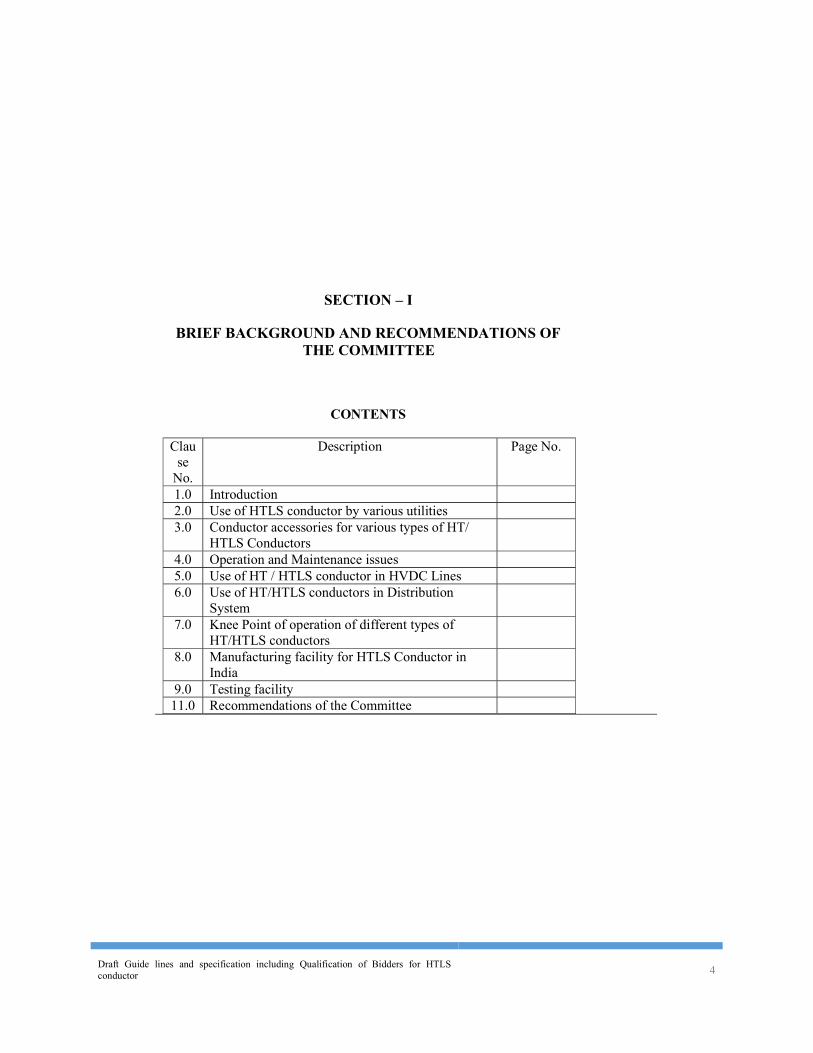
SECTION – I
BRIEF BACKGROUND AND RECOMMENDATIONS OF THE COMMITTEE
CONTENTS
Clause
No. Description Page No.
1.0 Introduction 2.0 Use of HTLS conductor by various utilities 3.0 Conductor accessories for various types of HT/
HTLS Conductors
4.0 Operation and Maintenance issues 5.0 Use of HT / HTLS conductor in HVDC Lines 6.0 Use of HT/HTLS conductors in Distribution
System
7.0 Knee Point of operation of different types of HT/HTLS conductors
8.0 Manufacturing facility for HTLS Conductor in
India
9.0 Testing facility 11.0 Recommendations of the Committee
Draft Guide lines and specification including Qualification of Bidders for HTLS conductor 5
SECTION - I
BRIEF BACKGROUND AND RECOMMENDATIONS OF THE COMMITTEE
1.0 Introduction: 1.1 In India, ACSR and AAAC are commonly used conductors for transmission of Power on
overhead lines for transmission and distribution system. The enhancement in power transmission capacity in existing corridor, reduction in losses and optimization of Right of Way (RoW) etc. of electric network is the need of the hour. New generation High Performance Conductor (HPC) would help electric power delivery system for efficient transmission of energy by way of enhancement of power flow per unit (or meter) of Right of Way (RoW) and reduction in losses under normal as well as under emergency condition and can address issues like growing congestion in existing corridor of transmission / distribution network and Right of Way (RoW) problems.
1.2 The conventional ACSR and AAAC are designed to operate continuously at temperature of 850
C and 950 C respectively. High Temperature Low Sag (HTLS) conductors are designed to operate continuously at temperature of at least 1500 C. Some of these HTLS conductors can be operated as high as 2500 C. The new material used in HTLS conductor differs from conventional steel reinforced ACSR. The new material includes INVAR steel (Fe-Ni alloy), temperature resistant Aluminium-Zirconium (Al-Zr) alloys, annealed aluminium, high strength steel, and both metal & polymer matrix composites. A conductor in general is a simple combination of core and aluminium / aluminium alloy. HTLS conductor is stranded with combination of aluminium or aluminium alloy wires for conductivity, and reinforced by core wires. The six basic types of HTLS conductors are ZTACIR (with INVAR steel core), GZTACSR (with a gap between the steel core and inner layer of trapezoidal aluminium wires), ZTACSR (with steel core), ACSS (with steel core), Zirconium – Aluminium conductors with metal matrix composite core (for example ACCR) and annealed aluminium conductors with organic matrix composite core (for example ACCC). The TACSR, GZTACSR, ACSS and ACCR are available with both round wire and trapezoidal Al-Zr alloy wires in the outermost layer. ACCC uses only trapezoidal annealed aluminium wires. GZTACSR, commonly known as Gap type conductor, is filled with heat resistant grease (filler) to reduce friction between the steel core and aluminium layer and to prevent water penetration.
1.3 The ordinary hard drawn aluminium used in conventional ACSR starts annealing and losing
strength at 930C and not suitable for long term use at temperature above this. Al-Zr aluminium wires have essentially the same conductivity and tensile strength as ordinary Electrical Conductor (EC) Grade aluminium wire but can operate continuously at temperatures upto 1500C – 2000C. Fully annealed aluminium wires are chemically identical to ordinary hard drawn aluminum and have much reduced tensile strength, but can operate indefinitely at temperatures even higher than 2500C without any change in mechanical properties of aluminium.
1.4 The introduction of novel conductor material technology is not new. However, in India since last
few years, the need for use of High Temperature (HT) / High Temperature Low Sag (HTLS) conductors in some corridors have been felt. The power flow in those corridors has increased and congestion has been reduced by using such conductors. Such conductor would be required where the power transfer over the line is constrained due to consideration of thermal loading. In Intra-state transmission system, requirement of such conductor is expected at 220kV, 132kV and 66kV level. The requirement of such conductor may not be much in ISTS, which is dominated by 400kV and 765kV network. In case of ISTS lines, the HT/ HTLS conductor would be a good substitute to Quad bundle ACSR and AAAC conductor, particularly at 400kV level when line length is short.
1.5 HT / HTLS conductor can be considered for reconductoring of existing lines and can also be
used in new lines. The cost of such conductor is about 2 to 3 times the cost of conventional
Draft Guide lines and specification including Qualification of Bidders for HTLS conductor 6
ACSR / AAAC conductors. The terminal equipment rating at substations needs to be examined for enhancement of power transfer in a line. Moreover, for new lines, proper system studies need to be carried out to identify the corridors for use of such conductor. The use of HTLS conductors need to be considered on case to case basis based on techno-economic analysis over the life cycle.
2.0 Use of HTLS conductor by various utilities 2.1 The Central Transmission Utility (CTU)/ PGCIL, few State Transmission Utilities like UPPTCL
(UP), MSETCL (Maharashtra), WBSETCL (West Bengal), OPTCL (Odisha) and some private utilities like Tata Power, Torrent Power, CESC have already used such type of conductor in transmission line corridors which are getting overloaded / exceeding the thermal loading limits of the existing conductor. Some state utilities like GETCO (Gujarat) and RRVPNL (Rajasthan) are planning for using such conductors in transmission line corridors requiring enhancement of power flow.
2.2 POWERGRID has used three types of HTLS conductor i.e. INVAR, GAP and composite core.
INVAR core based conductor has been used for good number of lines where as GAP type conductor has been used in three projects and composite core conductor has been used for the first time in 220kV lines for Delhi Transco Ltd. (DTL) consultancy projects. With INVAR core based conductor, POWERGRID has not faced any problem till date. But with GAP conductor, difficulty was faced during erection and accordingly PGCIL is not using GAP type conductor presently.
2.3 Tata Power has used only ACCC conductor in two lines one each at 22kV (5km) and 220 kV
(8km) level, similarly ACCR/3M conductor has been used in one line at 110kV (8km) level. 2.4 OPTCL has used HTLS conductor for reconductoring of three 132kV lines [line lengths are
6km, 6km and 25km]. The work has already been completed to replace ACSR panther conductor by ACCC. The line was originally designed for maximum sag corresponding to ACSR Panther conductor with maximum operating temperature of 75°C. OPTCL is further planning for reconductoring of two more 132kV lines in near future [line length is 17km and 12km].
2.5 WBSETCL has exclusively considered ACCC conductor for replacing the conventional ACSR
panther conductor in two existing 132kV lines. Three more 132kV lines are being considered for reconductoring using ACCC conductor.
2.6 Due to RoW problem, infringement in safety clearance requirement and congestion in NCR
region, UPPTCL has used ACCC as well as INVAR core conductor for reconductoring of 132kV line. The reconductoring of line was taken up along with replacement of busbar conductor in the associated substations.
2.7 CESC has used GAP type conductor in 220kV double circuit lines. 2.8 The details of various types of HTLS conductors used by above utilities are enclosed as
Annexure- ….. 2.9 It is difficult to comment on performance of such conductor as current / power flow in the line
has not reached the level for which it has been designed. 3.0 Conductor accessories for various types of HT/ HTLS Conductors:
The HTLS conductor & accessories must be designed to operate reliably in demanding conditions that combine high temperature operation under a broad spectrum of mechanical and electrical load. The conductor and accessories must resist wide range of transient mechanical & thermal loads such as fault current, lightning strikes, galloping events and ice loading. The contact between dissimilar materials may cause excessive corrosion in some environments. The hardware and accessories (connected electrically and mechanically to the
Draft Guide lines and specification including Qualification of Bidders for HTLS conductor 7
conductor) should be designed and tested to ensure that conductor retain its performance with accessories under normal as well as under emergency conditions and are compatible for the conductor. At present all fittings and accessories for various types of HT/HTLS conductors are being imported except for ACSS type of conductors which are easily available locally. M/s Tag corporation is in the process of manufacturing accessories for HT/HTLS conductors. With increase in demand for HT/HTLS conductors, few more manufacturers may show interest to manufacture the accessories and hardware fittings for such conductors. At present the cost of conductor accessories is exorbitantly high. Once the indigenous production of accessories for HT/HTLS conductor starts, the cost will come down. This will happen only if there is increase in demand for such conductors.
4.0 Operation and Maintenance issues:
As far as INVAR core based conductors are concerned, the operation maintenance and erection commissioning is more or less similar to conventional ACSR conductors. The composite materials have a more limited ability to conform to a bend radius than conventional engineering metals and alloys, such as steel & aluminium, since they have a limited strain to failure and have no plasticity. The minimum bending radius must not exceed the manufacturer’s specification. The composites are highly anisotropic, i.e, they have good tensile strength but lower shear, transverse and torsional strength. Thus composite materials require careful handling and care needs to be taken in choosing the correct diameter sheaves (i.e. travellers), bullwheel-tensioner and conductor reels, to prevent failure or overstressing. It is difficult to notice about any damage to the Carbon core of CCC conductor during erection. Hence after erection such unnoticed damage during erection may lead to snapping of conductor. The erection technique of GAP type conductor is different from other types of conductors. The steel core of GAP type conductor needs to pre-tensioned for 8 to 12 hours before stringing of the conductor in a particular section. Special tools are required during erection of GAP type and CCC conductor. Skill is required for installation of dead-end on GAP conductor. In case of snapping of GAP type conductor, mid span jointing is not possible and entire section needs to be replaced. Hence long shutdown period, which is not permitted in most of the cases, is required in case of GAP type conductors
5.0 Use of HT / HTLS conductor in HVDC Lines:
Quad bundle ACSR conductors are being used in HVDC line not only to meet the requirement of higher current as well as electric field. Hence application HT / HTLS conductor is not cost effective for HVDC system.
6.0 Use of HT/HTLS conductors in Distribution System:
HTLS conductor can be considered for use in distribution system where utility can get more benefits in terms of technical loss. But initial investment cost will be high, which can be recovered in a short span of time. Moreover, the demand from distribution sector is yet to come from utilities because of high cost of HT/HTLS conductor.
7.0 Knee Point of operation of different types of HT/HTLS conductors:
For High Temperature conductors, since aluminium has a larger Coefficient of Thermal Expansion (CTE) than core, the thermal elongation properties of the core control the maximum sag of the conductor. With heating, the aluminium will transfer its mechanical load to the core resulting in the core carrying most, if not all, of the mechanical load. The knee point at which the conducting envelope of conductor transfers its mechanical load to the core of conductor (i.e the point at which slope of strain vs temperature line changes) is different for different types of HT/HTLS conductors. The knee point of operation of GAP type conductor is much lower (i.e. it is the stringing temperature for GAP type conductor) than other types of HT/HTLS conductors. The advantage of sag is generally realized after knee point and hence GAP type conductor provides advantage over other types of HT/HTLS conductors. But the transmission line is designed for maximum sag at highest operating temperature and hence
Draft Guide lines and specification including Qualification of Bidders for HTLS conductor 8
HT/HTLS conductor should meet the sag / ground clearance requirement of utilities at highest operating temperature.
8.0 Manufacturing facility for HTLS Conductor in India 8.1 The HTLS conductor with Invar core has been supplied by M/s APAR Ind., M/s STL, and M/s
Gupta Power. The ACCC conductor has been supplied by M/s APAR, and M/s Sterlite. M/s Gupta Power has been awarded contract for supply of ACCC conductor to OPTCL. Similarly ACSS conductor has been supplied by M/s APAR Ind., M/s STL, and M/s HUIL. The GAP conductor and 3M conductor has been supplied by M/s Lamifil and M/s 3M. The INVAR core and polymer composite matrix core of CCC conductor are being imported. However, the conducting part / envelope of conductor is being manufactured in India. The conductor accessories are being imported by all manufacturers.
9.0 Testing facility 9.1 The constituent materials used in HT / HTLS conductors very. Some cores are common steel
strands coated with zinc (galvanized), zinc alloy or aluminium (aluminium clad, aluminium-5% mischmetal). Other conductors utilize relatively new materials such as fiber reinforced aluminium composites or fibre reinforced polymer composites. The required tests and test methods will differ depending on materials. All Type test facility is not available in India and many of the type tests are being carried out outside the country which adds to the cost of project. All testing facility should be created in India to save foreign exchange.
9.2 Sometimes the users / Power utilities in India are going for one specific type of conductor
although other types of conductors are also available to cater to similar requirement. Moreover, it is understood that there is wide variation in cost of various types of High Temperature (HT) / High Temperature Low Sag (HTLS) conductors. In the process the utilities are not getting the product at a competitive price as competition is restricted and as a result the overall cost of the project is likely to increase. Competition generally leads to significant benefits to consumers through reduction in capital cost. It will also facilitate the price to be determined competitively.
10.0 The committee deliberated on HLTS conductor and some guide lines (based on inputs from users / Power utilities and the manufacturers) including Technical specification for HTLS conductors & their accessories and Qualification of Bidders has been formulated for the benefit of users
11.0 RECOMMENDATIONS OF THE COMMITTEE Based on the deliberations, the recommendations of the committee are as follows. 11.1 High Temperature (HT) / High Temperature Low Sag (HTLS) conductors can address issues
like growing congestion in existing corridor of transmission / distribution network, enhancement of power flow per unit (or meter) of Right of Way (RoW) and reduction in losses under normal as well as under emergency condition.
11.2 High Temperature (HT) / High Temperature Low Sag (HTLS) conductors should be
considered in those corridors where the power transfer over the line is constrained due to consideration of thermal loading of conductor. In Intra-state transmission system, requirement of such conductor is expected at 220kV, 132kV and 66kV level. In case of ISTS lines, the HT/ HTLS conductor would be a good substitute to Quad bundle ACSR and AAAC conductor, particularly at 400kV level when line length is short. Application HT / HTLS conductor may not be cost effective for HVDC system and for 765kV and above voltage system.
11.3 HT / HTLS conductor can be considered for reconductoring of existing lines and can also be
used in new lines. The terminal equipment rating at substations needs to be examined for
Draft Guide lines and specification including Qualification of Bidders for HTLS conductor 9
enhancement of power flow in a line. However, for new lines, proper system studies need to be carried out to identify the corridors for use of such conductor.
11.4 The use of HTLS conductors need to be considered on case to case basis based on techno-
economic analysis over the life cycle. 11.5 HTLS conductor may be considered for use in distribution system where utility can get more
benefits in terms of technical loss although initial investment cost will be high. 11.6 Many of the type tests required for HTLS conductor are being carried out outside the country
which adds to the cost of project as all Type test facility is not available in India. The testing facility should be created in India to save foreign exchange.
11.7 The HTLS conductor with composite cores needs careful handling. Composite materilas are
highly anisotropic, i.e, they have good tensile strength but lower shear, transverse and torsional strength. Thus composite materials require careful handling and care needs to be taken in choosing the correct diameter sheaves (i.e.travellers), bullwheel-tensioner and conductor reels, to prevent failure or overstressing.
11.8 The erection of HTLS conductor should be carried out under the supervision of conductor
supplier / manufacturer. The manufacturers’ recommendation should be followed during erection and commissioning of HTLS conductor.
11.9 The state utilities should go for vendor development programme in line with PGCIL for
promoting complete indigenization of the product. 11.10 In the bidding process, generic name of conductor like CCC, GAP conductor etc should only
used by the users / Power utilities instead of patented names of manufacturer (s) for example ACCC, 3M etc.
11.11 The users / Power utilities should not invite bids for one specific type of HTLS conductor as
other types of HTLS conductors are also available to cater to similar requirement. In the process the utilities will get the product at a competitive price as competition generally leads to significant benefits to consumers through reduction in capital cost.
*********************************************************************************** ACSS: Aluminium Conductor Steel Supported TACSR: Thermal Resistant Aluminium Alloy Conductor Steel Reinforced ZTACSR: Super Thermal Resistant Aluminium Alloy Conductor Steel Reinforced ZTACIR: Super Thermal Resistant Aluminium Alloy Conductor Invar Reinforced GZTACSR: Gap Type Super Thermal Resistant Aluminium Alloy Conductor Steel Reinforced ACCC: Aluminium Alloy Conductor with Composite Core
Draft Guide lines and specification including Qualification of Bidders for HTLS conductor 10
SECTION – II
QUALIFICATION OF THE BIDDER
Draft Guide lines and specification including Qualification of Bidders for HTLS conductor 11
SECTION – II
QUALIFICATION OF THE BIDDER 1.0 Qualification of Bidder Qualification of bidder will be based on meeting the minimum pass/fail criteria specified below regarding the Bidder’s Technical Experience and Financial Position as demonstrated by the Bidder’s responses in the corresponding Bid Schedules. The bid can be submitted by:-
(i) a Qualified Manufacturer meeting the specified requirements given under
para 1.1 & 1.3 , or (ii) Qualified Licensee of a Qualified Manufacturer (Requirements specific to
Licensor-Licensee route are given under Para 1.1(c), 1.2 & 1.3 below), or (iii) a Joint Venture of two firms (Requirements specific to Joint Ventures are
given under Para 1.1(c) and 1.4 below). The Employer may assess the capacity and capability of the bidder to ascertain that the bidder can successfully execute the scope of work covered under the package within stipulated completion period. The assessment shall inter-alia include (i) document verification; (ii) bidder’s works/ manufacturing facilities visit; (iii) manufacturing capacity, details of work executed, works in hand, anticipated in future & balance capacity available for the present scope of work; (iv) details of plant and machinery, manufacturing and testing facilities, manpower and financial resources; (v) details of quality system in place; (vi) past experience and performance; (vii) customer feedback; (viii) Banker’s feedback etc. Utility reserves the right to waive minor deviations if they do not materially affect the capability of the Bidder to perform the contract.
1.1 Technical Experience:
1.1 (a) The Qualified Manufacturer shall be a manufacturer of conductor for the last five years.
The Qualified Manufacturer should have manufactured, tested and supplied at least two hundred (200) km of High temperature low sag (HTLS) conductor of same technology as that of the conductor being offered in this package having minimum * thirty seven (37) number of strands or 200 sq. mm. aluminum cross section area / ** thirty three (33) number of strands or 150 sq. mm. aluminum cross section area / *** thirty (30) number of strands or 100 sq. mm. aluminum cross section area / having at least same or more number of strands as that of the conductor being offered in last ten
Draft Guide lines and specification including Qualification of Bidders for HTLS conductor 12
(10) years as on originally scheduled date of bid opening, i.e. 00-00-20-- and the same should have been in satisfactory operation$ for a period of at least two (2) years as on the date of bid opening mentioned above.
[ * Applicable for 400kV, strike out if not applicable, ** Applicable for 220kV, strike out if not applicable, *** Applicable for 132kV, strike out if not applicable] OR
1.1(b)An indigenous manufacturer not meeting the requirement stipulated in clause 1.1(a) above can also participate provided he meets the following requirements as on schedule date of bid opening mentioned above:
The indigenous conductor manufacturer must be a manufacturer of conductor for the last five years.
The indigenous conductor manufacturer must have manufactured, tested, supplied at least one hundred (100) km of High temperature low sag (HTLS) conductor of same technology as that of the conductor being offered in this package having minimum * thirty seven (37) number of strands or 200 sq. mm. aluminum cross section area / ** thirty three (33) number of strands or 150 sq. mm. aluminum cross section area / *** thirty (30) number of strands or 100 sq. mm. aluminum cross section area / having at least same or more number of strands as that of the conductor being offered in last ten (10) years as on originally scheduled date of bid opening as mentioned above and the same should have been in satisfactory operation$ for a period of at least one (1) year as on the date of bid opening mentioned above.
[ * Applicable for 400kV, strike out if not applicable, ** Applicable for 220kV, strike out if not applicable, *** Applicable for 132kV, strike out if not applicable]
Note: In case of clause 1.1(b) above , the warranty obligations for additional period of two (2) years over and above the warranty period as specified in the bidding documents shall be applicable.
$ Satisfactory operation means Certificate issued by the Employer certifying the operation without any adverse remark.
OR 1.1(c) Indigenous conductor manufacturer not meeting the qualification
requirements stipulated at para 1.1(a) & 1.1(b) above can submit bid as:-
Draft Guide lines and specification including Qualification of Bidders for HTLS conductor 13
(i) a Qualified Licensee of a Qualified Manufacturer (Licensor) meeting the requirement stipulated at para 1.1(a) (Requirements specific to Licensor-Licensee route are given under Para 1.2 & 1.3 below), or
(ii) one of the partners in Joint Venture of two firms (Requirements specific
to Joint Ventures are given under Para 1.4 below).
provided that:- The Indigenous conductor manufacturer is a manufacturer of conductor for the last five years & has manufactured, tested and supplied at least one thousand (1000) km of ACSR/ AAAC/ ACAR/ AACSR conductor having at least same or more number of strands as that of the conductor being offered in the package during last five (5) years as on the date of bid opening mentioned above. Note: In case of Clause 1.1(c) above, indigenous conductor manufacturers participating as a Qualified Licensee or as a partner in JV with Qualified manufacturer shall provide warranty obligations for additional period of two (2) years over and above the warranty period as specified in the bidding documents shall be applicable.
1.2 Requirements specific to Licensor-Licensee route:- In case of bid by an Indigenous conductor manufacturer as a Qualified Licensee of a Qualified Manufacturer (Licensor) meeting the qualification requirements set forth in para 1.1(a), the Licensee should meet the following conditions: i) Qualified Licensee shall have adequate design infrastructure and manufacturing
facility and capacity and procedures including quality control. ii) A Qualified Licensee of a Qualified Manufacturer shall comply with all of the
following requirements and furnish a joint undertaking by the licensor along with the bidder in its bid (Form enclosed at ---------------of the Bidding Documents).
a) Any design undertaken by the Licensee shall be approved by the Licensor.
Draft Guide lines and specification including Qualification of Bidders for HTLS conductor 14
b) Manufacturing by the Licensee shall be done with the approval of the Licensor under a quality assurance programme approved and monitored by the Licensor.
c) In addition to the Contract Performance Security to be furnished by the
bidder, the Licensor shall furnish back up performance security in the form of bank guarantee for 5 % of the CIF/ Ex-works cost of the HTLS conductor as per format provided in the bid documents for successful performance of HTLS conductor to be manufactured and supplied by the Licensee under the contract.
d) Licensor must guarantee sequential and timely supply of materials and
submission of technical information and data as desired by the Employer so as to meet the overall construction schedule and
e) The agreement between Licensee and Licensor (copy to be submitted along
with the bid) shall be valid for a period of at least five (5) years after the guarantee period of equipment and materials under supply is over.
In case bidder is a holding company, the technical experience referred to in clause 1.1 above shall be of that holding company only (i.e. excluding its subsidiary/group companies). In case bidder is a subsidiary of a holding company, the technical experience referred to in clause 1.1 above shall be of that subsidiary company only (i.e. excluding its holding companies).
1.3 Financial Position For the purpose of the particular bid, bidders shall meet the following minimum criteria:
a) Net worth for last 3 financial years should be positive b) Minimum Average Annual Turnover* (MAAT) for best three years i.e. 36
months out of last five financial years of the bidder should be US$ --- Million or Indian Rs. --- Million or equivalent.
* Note: Annual total income as incorporated in the profit and loss account except
non-recurring income e.g. sales of fixed assets. c) Bidder shall have liquid assets (L.A) or/and evidence of access to or availability
of credit facilities of not less than US$ --- Million or Indian Rs. --- Million or equivalent.
Draft Guide lines and specification including Qualification of Bidders for HTLS conductor 15
For bidders to qualify for more than one package, their financial position specified at 1.3 (b) & (c) shall not be less than the sum of the requirement for the packages they propose to qualify for.
d) In case Bid is submitted by a Qualified Licensee of a Qualified Manufacturer, the
requirements stipulated at Clause 1.3 a), b) & c) above shall be individually met by the Licensee as well as the Licensor.
In case bidder is a holding company, the financial position criteria referred to in clause 1.3 above shall be of that holding company only (i.e. excluding its subsidiary/group companies). In case bidder is a subsidiary of a holding company, the financial position criteria referred to in clause 1.3 above shall be of that subsidiary company only (i.e. excluding its holding company).
1.4 Requirements specific to Joint Ventures:
In case, bid is submitted by a Joint Venture (JV) of two firms as partners, the JV shall meet collectively the complete requirement mentioned at clause 1.1(a) & (c), 1.3(b) & 1.3(c) above and they must meet the following requirements: (i) One of the partners(s) of JV shall meet the Technical Experience criteria
stipulated under para 1.1(a) and,
(ii) The other partner of JV should be an Indigenous conductor manufacturer meeting the technical experience criteria stipulated under 1.1(c) and should have adequate design infrastructure and manufacturing facility and capacity and procedures including quality control provided that:-
a) Indigenous Conductor Manufacturer enter into a valid technology transfer agreement for design, manufacturing, testing and supply of HTLS conductor based on technological support with the other partner of JV who meets the Technical Experience criteria stipulated in 1.1(a) above and,
b) A legally enforceable undertaking jointly by such Indigenous conductor
Manufacturer and partner of JV who meets the Technical Experience criteria stipulated in 1.1(a) above (Form enclosed at ------- of bidding document) is furnished along with the bid, to guarantee quality, timely supply, performance and warranty obligations as specified, for the conductor to be manufactured and supplied from the works of such Indigenous conductor Manufacturer in India and,
c) In such case, each of the partners of JV, shall be required to supply at least
33% of the total quantity of HTLS conductor iii) All the partners of the JV shall meet individually the Financial Position criteria
given at 1.3(a) above.
Draft Guide lines and specification including Qualification of Bidders for HTLS conductor 16
iv) The lead partner shall meet not less than 40% of the Financial Position minimum criteria given at Para 1.3 (b) & 1.3 (c)
v) The other partner shall meet not less than 25% of the minimum Financial Position
criteria given at Para 1.3 (b) & 1.3 (c) The figure of average annual turnover and liquid assets/credit facilities for each of the partners of the JV shall be added together to determine the JV’s compliance with the minimum qualifying criteria set out in para 1.3 (b) & 1.3 (c) above.
1.5 The bidder shall submit documentary evidence in support of qualification requirement stipulated above.
The warranty obligations for indigenous conductor manufacturers for additional period of two (2) years over and above the warranty period as specified in Clause 1.1 (b) and 1.1 (c) are to be included in the bidding documents.
Draft Guide lines and specification including Qualification of Bidders for HTLS conductor 17
SECTION – III
GENERAL INFORMATION AND SCOPE
Draft Guide lines and specification including Qualification of Bidders for HTLS conductor 18
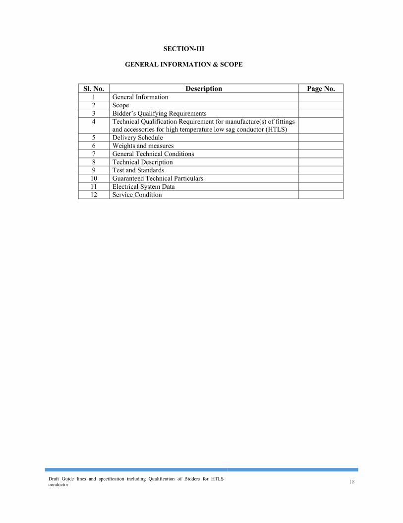
SECTION-III
GENERAL INFORMATION & SCOPE
Sl. No. Description Page No.
1 General Information 2 Scope 3 Bidder’s Qualifying Requirements 4 Technical Qualification Requirement for manufacture(s) of fittings
and accessories for high temperature low sag conductor (HTLS)
5 Delivery Schedule 6 Weights and measures 7 General Technical Conditions 8 Technical Description 9 Test and Standards
10 Guaranteed Technical Particulars 11 Electrical System Data 12 Service Condition
Draft Guide lines and specification including Qualification of Bidders for HTLS conductor 19
SECTION-III
GENERAL INFORMATION & SCOPE
1. General Information 1.1 The material covered in this specification shall be used in ---km of X to Y ---
kV S/C or D/C (or S/C on D/c Towers) transmission line [ e.g. 38km of Gaya to Kodrma 400kC D/c (Quad) transmission line].
2. Scope 2.1 The scope covers design, manufacturing, testing & supply of High
Temperature Low Sag (HTLS) conductor and associated fittings and accessories sutable for the offered HTLS conductor viz. i) suspension clamps suitable for suspension insulator strings (free centre type alongwith Preformed Armour Rods or Armour Grip Suspension Clamp), ii) Suspension Clamps suitable for suspension pilot insulator strings (Envelope type), iii) Compression type dead end clamps suitable for tension insulator strings, iv) Mid-span compression joints, v) Repair Sleeves, vi) Vibration Dampers, vii) Bundle Spacers for twin bundle conductor for line & viii) Rigid Spacers for jumper for twin bundle conductor etc.
2.1 The material to be supplied on final destination at site basis as covered in this volume shall be designed, manufactured and tested as per the requirements specified. Final Destination shall mean the stores established by the Contractor of the Owner along the Transmission Lines.
2.2 The materials covered here under this specification shall be supplied complete in all respects, including all components, fittings and accessories which are necessary or are usual for their efficient performance and satisfactory maintenance under the various operating and atmospheric conditions. Suppler of HTLS conductor shall be responsible for ensuring compatibility of associated with fittings and accessories and satisfactory performance of complete conductor system (alongwith associated with fittings and accessories) for continuous operation at the designed continuous operating temperature of the offered HTLS conductor. Such parts shall be deemed to be within the scope of the Contract, whether specifically included or not in the Specification or in the Contract Schedules. The Supplier shall not be eligible for any extra charges for such fittings, etc.
The details of the materials required in the package under this Specification are mentioned in the bidding documents.
2.3 The installation & stringing of the offered HTLS conductor for the above
transmission line shall be carried out by the transmission line contractor under supervision of the HTLS conductor supplier.
The supplier shall supervise the stringing at site as per the approved stringing procedure. Site visit for supervision shall be carried out as per instruction of Purchaser / utility (Utility name may be indicated e.g. POWERGRID). The mandays for site supervision is as per schedule of Bid Proposal Sheets (BPS). The supervision/Inspection work in supplier’s scope shall mainly include
Draft Guide lines and specification including Qualification of Bidders for HTLS conductor 20
inspection as per stringing procedure, proper location of drum site, installation of stringing blocks/pulley, proper sagging, proper installation of its fittings & accessories, proper tension as per sag-Tension chart etc.
Charges for supervision of installation & stringing of the offered HTLS conductor shall be for complete scope of work as per the Technical specification.
2.3 The above stringing work including installation of its fittings & accessories shall be supervised by a team of supplier’s engineers / supervisory staff/ workmen already experienced in stringing work associated with the type of HTLS conductor being supplied. The bidder shall furnish experience details of the engineers /supervisory staff proposed to be deployed. The supplier shall co-ordinate with the line contractor and train their workers.
3. Bidder's Qualifying Requirements The qualifying requirement shall be as specified in ‘Special Condition of
Contract (Vol-I) of the bidding documents. 4. Technical Qualification Requirement for manufacture(s) of fittings and
accessories for high temperature low sag conductor (HTLS). The Bidder shall offer fittings and accessories for HTLS covered under the
scope of supply from the qualified manufacture(s) meeting the following requirements: (a) The qualified manufacturer (s) should have designed, manufactured,
tested and supplied fittings for suspension & tension strings and accessories for conductor for the specified voltage (indicate voltage level e.g. 400 kV) or above voltage transmission line. Further, the qualified manufacturer(s) for any individual item(s) of fittings and accessories covered under the package should have designed, manufactured, tested and supplied the item(s) of fittings and accessories covered under the package or the item(s) of similar nature/ comparable nature for application with HTLS conductor being supplied and the same should have been in satisfactory operation for a minimum period of two (2) years as on date of bid opening.
The manufacturer(s) meeting the above requirement for any individual item or items shall be considered qualified for the respective item or items only.
(b) However, if the proposed manufacturer is not meeting the above requirements on its own, he should be qualified licensee of a qualified manufacturer meeting the above specified requirements. i) Manufacturer/licensees shall have adequate design infrastructure
and manufacturing facility and capacity and procedures including quality control.
ii) A qualified Licensee of a qualified manufacturer shall mean all of the following: a) any design undertaken by the licensee shall be approved
by the licenser
Draft Guide lines and specification including Qualification of Bidders for HTLS conductor 21
b) Manufacture by the licensee shall be done with the approval of the licensor and Employer under a quality assurance programme approved and monitored by the licenser.
c) Licensee must furnish back-up guarantee from the licenser for individual and overall performance of all equipment and materials supplied under the contract.
d) Licenser must guarantee sequential and timely supply of equipments and materials and submission of technical information and data as desired by the Employer so as to meet the overall construction schedule and
e) The agreement between licensee and licenser submitted along with the bid shall be valid for a period of at least five (5) years after the guarantee period of equipment and materials under supply is over.
6. Delivery Schedule The delivery schedule shall be as specified in the bidding documents.
7. Weights and Measures All weights and measures shall be in System International (S.I.) units. All
fasteners shall be of Metric size only.
8. General Technical Conditions 8.1 The following provisions shall supplement all the detailed technical
specifications and requirements brought out in the accompanying Technical Specifications. The Bidder’s proposal shall be based on the use of equipment and materials complying fully with the requirements, specified herein.
The Bidder shall furnish clause-by-clause commentary (with detailed
technical data as required) on the Technical Specifications demonstrating the goods substantial responsiveness to the specifications or deviations and exceptions to the provisions of the Technical Specification.
8.2 Equipment Performance Guarantee 8.2.1 The performance requirements of the items are detailed separately in this
Specification. These guarantees shall supplement the general performance guarantee provisions covered under General Terms and Conditions of Contract in clause entitled ‘Guarantee’.
8.2.2 Liquidated damages for not meeting specified performance shall be assessed
and recovered from the Supplier. Such liquidated damages shall be without any limitation whatsoever and shall be in addition to damages, if any payable under any other clause of Conditions of Contract.
Draft Guide lines and specification including Qualification of Bidders for HTLS conductor 22
8.3 Engineering Data 8.3.1 The furnishing of engineering data by the Supplier shall be in accordance
with the appropriate Schedule appended to this document. The review of these data by the Owner will cover only general conformance of the data to the specifications and drawings. This review by the Owner may not indicate a thorough review of all dimensions, quantities and details of the equipment, materials, any devices or items indicated or the accuracy of the information submitted. This review and/or approval by the Owner shall not be considered by the Supplier, as limiting any of his responsibilities and liabilities for mistakes and deviations from the requirements, specified under these Specifications and documents.
8.3.2 All engineering data submitted by the Supplier after final process including
review and approval by the Owner shall form part of the Contract Document and the entire works performed under these Specifications shall be performed in strict conformity, unless otherwise expressly requested by the Owner in writing.
8.4 Drawings 8.4.1 All drawings submitted by the Supplier including those submitted at the time
of bid shall be in sufficient detail to indicate the type, size, arrangement, dimensions, material description, Bill of Materials, weight of each component, break-up for packing and shipment, fixing arrangement required, the dimensions required for installation and any other information specifically requested in the Specifications.
8.4.2 Each drawing submitted by the Supplier shall be clearly marked with the
name of the Owner, the unit designation, the Specification title, the Specification number and the name of the Project. All titles, noting, markings and in writings on the drawing shall be in English. All the dimensions should be to the scale and in metric units.
8.4.3 The drawings submitted by the Supplier shall be reviewed by the Owner as
far as practicable and shall be modified by the Supplier if any modifications and/or corrections are required by the Owner in compliance with Specifications. The Supplier shall incorporate such modifications and or corrections and submit the final drawings for approval. Any delays arising out of failure by the Supplier to rectify the drawings in good time shall not alter the Contract completion date.
8.4.4 The drawings shall be submitted for approval to the Owner.
8.4 5 Further, work by the Supplier shall be strictly in accordance with these
drawings and no deviation shall be permitted without the written approval of the Owner, if so required.
8.4.6 All manufacturing and fabrication work in connection with the equipment/
material prior to the approval of the drawings shall be at the Supplier’s risk. The Supplier may make any changes in the design which are necessary to
Draft Guide lines and specification including Qualification of Bidders for HTLS conductor 23
make the equipment conform to the provisions and intent of the Contract and such changes will again be subject to approval by the Owner. Approval of Supplier’s drawing or work by the Owner shall not relieve the Supplier of any of his responsibilities and liabilities under the Contract.
8.5 Manufacturing Schedule The Supplier shall submit to the Owner his manufacturing, testing and
delivery schedules of various items within thirty (30) days from the date of the Letter of Award in accordance with the delivery requirements stipulated. Schedules shall also include the materials and items purchased from outside Suppliers, if any.
8 6 Reference Standards 8.6.1 The Codes and/or Standards referred to in Specifications shall govern, in all
cases wherever such references are made. In case of a conflict between such Codes and/or Standards and the specifications, latter shall govern. Such Codes and/or Standards, referred to shall mean the latest revisions, amendments/changes adopted and published by the relevant agencies.
8.6.2 Other Internationally acceptable Standards which ensure equivalent or better
performance than those specified shall also be accepted.
8.7 Design Improvements 8.7.1 The Owner or the Supplier may propose changes in the Specification of the
equipment or quality thereof and if the parties agree upon any such changes, the Specification shall be modified accordingly.
8.7.2 If any such agreed upon change is such that it affects the price and schedule
of completion, the parties shall agree in writing as to the extent of any change in the price and/or schedule of completion before the Supplier proceeds with the change. Following such agreement, the provision thereof, shall be deemed to have been amended accordingly.
8.8 Quality Assurance 8.8.1 To ensure that the equipment under the scope of this Contract whether
manufactured within the Supplier’s Works or at his Sub-Supplier’s premises is in accordance with the specifications, the Supplier shall adopt suitable Quality Assurance Programme to control such activities at all points necessary.
Such programme shall be outlined by the Supplier and shall be finally
accepted by the Owner after discussions before the award of Contract. A Quality Assurance Programme of the Supplier shall generally cover but not limited to the following:
a) His organisation structure for the management and implementation of
the proposed Quality Assurance Programme.
Draft Guide lines and specification including Qualification of Bidders for HTLS conductor 24
(b) Documentation control system. (c) Qualification data for key personnel; (d) The procedure for purchases of materials. Parts/components and
selection of sub-Supplier’s services including vendor analysis, source inspection, incoming raw material inspection, verification of material purchases etc.
(e) System for shop manufacturing including process controls. (f) Control of non-conforming items and system for corrective action. (g) Control of calibration and testing of measuring and testing equipments. (h) Inspection and test procedure for manufacture. (i) System for indication and appraisal of inspection status. (j) System for quality audits. (k) System for authorising release of manufactured product to the Owner. (I) System for maintenance of records. (m) System for handling, storage and delivery and n) A Quality Plan detailing out the specific quality control procedure
adopted for controlling the quality characteristics of the product. The Quality Plan shall be mutually discussed and approved by the Owner
after incorporating necessary corrections by the Supplier as may be required.
8.8.2 Quality Assurance Documents The Supplier shall be required to submit all the Quality Assurance
Documents as stipulated in the Quality Plan at the time of Owner’s inspection of equipment/material.
8.8.3 The Owner or his duly authorised representatives reserves the right to carry
out Quality Audit and quality surveillance of the systems and procedures of the Supplier’s/his vendor’s Quality Management and Control Activities.
8.9 Owner’s Supervision 8.9.1 To eliminate delays and avoid disputes and litigation it is agreed between the
parties to the Contract that all matters and questions shall be resolved in accordance with the provisions of this document.
8.9.2 The manufacturing of the product shall be carried out in accordance with the
specifications. The scope of the duties of the Owner, pursuant to the contract, will include but not be limited to the following:
(a) Interpretation of all the terms and conditions of these Documents and
Specifications. (b) Review and interpretation of all the Supplier’s drawings, engineering
data etc
Draft Guide lines and specification including Qualification of Bidders for HTLS conductor 25
(c) Witness or authorise his representative to witness tests at the manufacturer’s works or at site, or at any place where work is performed under the Contract.
(d) Inspect, accept or reject any equipment, material and work under the Contract, in accordance with the Specifications.
(e) Issue certificate of acceptance and/or progressive payment and final payment certificate.
(f) Review and suggest modification and improvement in completion schedules from time to time, and
(g) Supervise the Quality Assurance Programme implementation at all stages of the works.
8.10 Inspection, Testing & Inspection Certificate 8.10.1 The Owner, his duly authorised representative and/or outside inspection
agency acting on behalf of the Owner shall have at all reasonable times access to the Supplier’s premises and works and shall have the power at all reasonable times to inspect and examine the materials and workmanship of the product during its manufacture and if part of the product is being manufacture or assembled at other premises or works, the Supplier shall obtain from the Owner and /or his duly authorised representative permission to inspect as if the equipment/ materials were manufactured or assembled on the Supplier’s own premises or works.
8.10.2 The Supplier shall give the Owner Inspector fifteen (15) days written notice
of any material being ready for testing. Such tests shall be to the Supplier’s account except for the expenses of the Inspector. The Owner/inspector, unless witnessing of the tests is waived, will attend such tests within fifteen (15) days of the date of which the equipment is notified as being ready for test/inspection or on a mutually agreed date, failing which the Supplier may proceed with the test which shall be deemed to have been made in the Inspector’s presence and he shall forthwith forward to the Inspector duly certified copies of tests in triplicate.
8.10.3 The Owner/Inspector shall, within fifteen (15) days from the date of
inspection as defined herein give notice in writing to the Supplier, of any objection to any drawings and all or any equipment and workmanship which in his opinion is not in accordance with the Contract. The Supplier shall give due consideration to such objections and shall make the modifications that may be necessary to meet the said objections.
8.10.4 When the factory tests have been completed at the Supplier’s or Sub-
Supplier’s works, the Owner inspector shall issue a certificate to this effect within fifteen (15) days after completion of tests but if the tests are not witnessed by the Owner/inspector, the certificate shall be issued within fifteen (15) days of receipt of he Supplier’s Test Certificate by the Owner/ Inspector. The completion of these tests or the issue of the certificate shall not bind the Owner to accept the equipment should it, on further tests after erection, be found not to comply with the Contract.
Draft Guide lines and specification including Qualification of Bidders for HTLS conductor 26
8.10.5 In all cases where the Contract provides for test whether at the premises or
works of, the Supplier or of any Sub-Supplier, the Supplier except where otherwise specified shall provide free of charge such item as labour , materials, electricity, fuel, water, stores, apparatus and instruments as may be reasonably demanded by the Owner inspector or his authorised representative to carry out effectively such tests of the equipment in accordance with the Contract and shall give facilities to the Owner/Inspector or to his authorised representative to accomplish testing.
8.10.6 The inspection by Owner and issue of Inspection Certificate thereon shall in
no way limit the liabilities and responsibilities of the Supplier in respect of the agreed Quality Assurance Programme forming a part of the Contract.
9. Technical Description 9.1 The technical description of the conductor and its fittings & accessories shall
be as specified in Section-II & III of this Technical Specifications. 10. Tests and Standards 10.1 Tests The following type, acceptance and routine tests and tests during manufacture
shall be carried-out on the material. For the purpose of this clause: 10.1.1 Type Tests shall mean those tests which are to be carried out to prove the
process of manufacture and general conformity of the material to this Specification. These tests shall be carried out on samples prior to commencement of commercial production against the order. The Bidder shall indicate his schedule for carrying out these tests.
10.1.2 Acceptance Tests shall mean those tests which are to be carried out on
samples taken from each lot offered for pre-dispatch inspection, for the purposes of acceptance of that lot.
10.1.3 Routine Tests shall mean those tests, which are to be carried out on the
material to check requirements which are likely to vary during production.
10.1.4 Tests During Manufacture shall mean those tests, which are to be carried out during the process of manufacture and end inspection by the Supplier to ensure the desired quality of the end product to be supplied by him.
10.1.5 The norms and procedure of sampling for these tests will be as per the
Quality Assurance Programme to be mutually agreed to by the Supplier and the Owner.
10.1.6 The standards and norms to which these tests will be carried out are listed against them. Where a particular test is a specific requirement of this Specification, the norms and procedure of the test shall be as specified in Annexure-A or as mutually agreed to between the Supplier and the Owner in the Quality Assurance Programme.
Draft Guide lines and specification including Qualification of Bidders for HTLS conductor 27
10.1.7 For all type and acceptance tests, the acceptance values shall be the values specified in this Specification or guaranteed by the Bidder, as applicable.
11. Guaranteed Technical Particulars 11.1 The Guaranteed Technical Particulars of the various items shall be furnished
by the Bidders in the prescribed schedules of the specifications. The Bidder shall also furnish any other schedule information as in their opinion is needed to give full description and details to judge the item(s) offered by them.
11.2 The data furnished in Guaranteed Technical Particulars should be the minimum or maximum value (as per the requirement of the specification) required. A Bidder may guarantee a value more stringent than the specification requirement. However, for testing purpose or from performance point of view, the material shall be considered performed successfully if it achieves the minimum/maximum value required as per the technical specification. No preference what so ever shall be given to the bidder offering better/more stringent values than those required as per specification.
12.0 Electrical System Data Nominal Voltage kV ---- (e.g. 400) Highest system voltage kV ---- (e.g 420) BIL (Impulse) kV (Peak) ---- (e.g.1550) Power frequency withstand voltage (Wet) kV (rms) ---- (e.g. 680) Switching surge withstand voltage (Wet) kV (rms) ----(e.g. 1050) Minimum Corona extinction voltage at 50 Hz AC
system under dry condition [for 400kV line] kV (rms) phase to earth
---- [e.g. 320(Min)]
Radio interference voltage at one MHz for phase to earth voltage of 305 kV under dry condition. [for 400kV line]
Micro Volts 1000 (Max)
13.0 Service Condition
Equipment/material to be supplied against this specification shall be suitable for satisfactory continuous operation under conditions as specified below: Maximum ambient temperature (Degree Celcius) 50 Minimum ambient temperature (Degree Celsius) ---- (e.g. 4 ) Relative humidity (% range) ---- (e.g.10-100)
Maximum annual rainfall & snowfall (Cm) as per published Meteorological/
climatological data Wind zone (as per IS: 875) ---- (e.g. 4 ) Maximum wind velocity (m/sec.) ---- [e.g. 47 m/sec. as per IS : 875]
Maximum altitude above mean sea level (Metres) ---- (e.g. Upto 1000 m) Isokeraunic level (days/years) --- (e.g. 50) Climate varies from moderately hot and humid tropical climate to cold climate.
Draft Guide lines and specification including Qualification of Bidders for HTLS conductor 28
SECTION – IV
TECHNICAL SPECIFICATION FOR
HTLS CONDUCTOR
Draft Guide lines and specification including Qualification of Bidders for HTLS conductor
SECTION-IV
TECHNICAL SPECIFICATION FOR HTLS CONDUCTOR
CONTENTS
Clause No. Description Page No. 1 Description of High Temperature Low Sag (HTLS)
Conductor and its Technical Requirements
2 Tests and Standards 3 Annexure A 4 Annexure B
Draft Guide lines and specification including Qualification of Bidders for HTLS conductor
SECTION-IV
TECHNICAL SPECIFICATION FOR HTLS CONDUCTOR
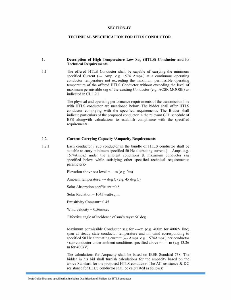
1. Description of High Temperature Low Sag (HTLS) Conductor and its Technical Requirements
1.1 The offered HTLS Conductor shall be capable of carrying the minimum specified Current (--- Amp. e.g. 1574 Amps.) at a continuous operating conductor temperature not exceeding the maximum permissible operating temperature of the offered HTLS Conductor without exceeding the level of maximum permissible sag of the existing Conductor (e.g. ACSR MOOSE) as indicated in Cl. 1.2.1
The physical and operating performance requirements of the transmission line with HTLS conductor are mentioned below. The bidder shall offer HTLS conductor complying with the specified requirements. The Bidder shall indicate particulars of the proposed conductor in the relevant GTP schedule of BPS alongwith calculations to establish compliance with the specified requirements.
1.2 Current Carrying Capacity /Ampacity Requirements 1.2.1 Each conductor / sub conductor in the bundle of HTLS conductor shall be
suitable to carry minimum specified 50 Hz alternating current (--- Amps. e.g. 1574Amps.) under the ambient conditions & maximum conductor sag specified below while satisfying other specified technical requirements/ parameters:-
Elevation above sea level = ---m (e.g. 0m) Ambient temperature: --- deg C (e.g. 45 deg C) Solar Absorption coefficient =0.8 Solar Radiation = 1045 watt/sq.m Emisitivity Constant= 0.45 Wind velocity = 0.56m/sec
Effective angle of incidence of sun’s rays= 90 deg Maximum permissible Conductor sag for ----m (e.g. 400m for 400kV line)
span at steady state conductor temperature and nil wind corresponding to specified 50 Hz alternating current (--- Amps. e.g. 1574Amps.) per conductor / sub conductor under ambient conditions specified above = ---- m (e.g 13.26 m for 400kV)
The calculations for Ampacity shall be based on IEEE Standard 738. The bidder in his bid shall furnish calculations for the ampacity based on the above Standard for the proposed HTLS conductor. The AC resistance & DC resistance for HTLS conductor shall be calculated as follows:
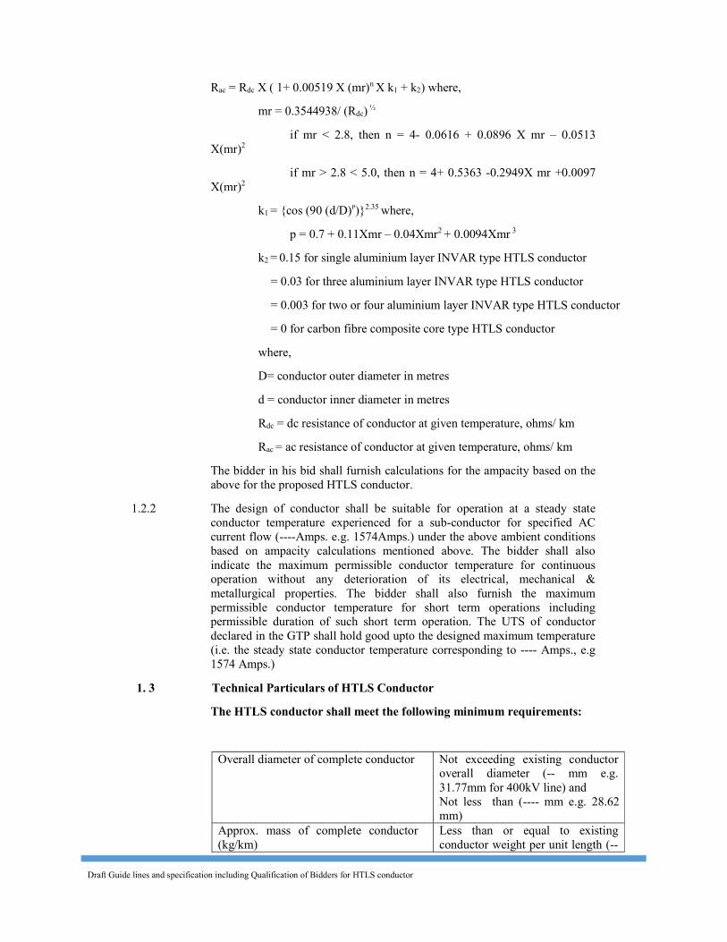
Draft Guide lines and specification including Qualification of Bidders for HTLS conductor
Rac = Rdc X ( 1+ 0.00519 X (mr)n X k1 + k2) where, mr = 0.3544938/ (Rdc) ½
if mr < 2.8, then n = 4- 0.0616 + 0.0896 X mr – 0.0513 X(mr)2
if mr > 2.8 < 5.0, then n = 4+ 0.5363 -0.2949X mr +0.0097 X(mr)2
k1 = {cos (90 (d/D)P)}2.35 where, p = 0.7 + 0.11Xmr – 0.04Xmr2 + 0.0094Xmr 3
k2 = 0.15 for single aluminium layer INVAR type HTLS conductor = 0.03 for three aluminium layer INVAR type HTLS conductor = 0.003 for two or four aluminium layer INVAR type HTLS conductor = 0 for carbon fibre composite core type HTLS conductor where, D= conductor outer diameter in metres d = conductor inner diameter in metres Rdc = dc resistance of conductor at given temperature, ohms/ km Rac = ac resistance of conductor at given temperature, ohms/ km The bidder in his bid shall furnish calculations for the ampacity based on the
above for the proposed HTLS conductor. 1.2.2 The design of conductor shall be suitable for operation at a steady state
conductor temperature experienced for a sub-conductor for specified AC current flow (----Amps. e.g. 1574Amps.) under the above ambient conditions based on ampacity calculations mentioned above. The bidder shall also indicate the maximum permissible conductor temperature for continuous operation without any deterioration of its electrical, mechanical & metallurgical properties. The bidder shall also furnish the maximum permissible conductor temperature for short term operations including permissible duration of such short term operation. The UTS of conductor declared in the GTP shall hold good upto the designed maximum temperature (i.e. the steady state conductor temperature corresponding to ---- Amps., e.g 1574 Amps.)
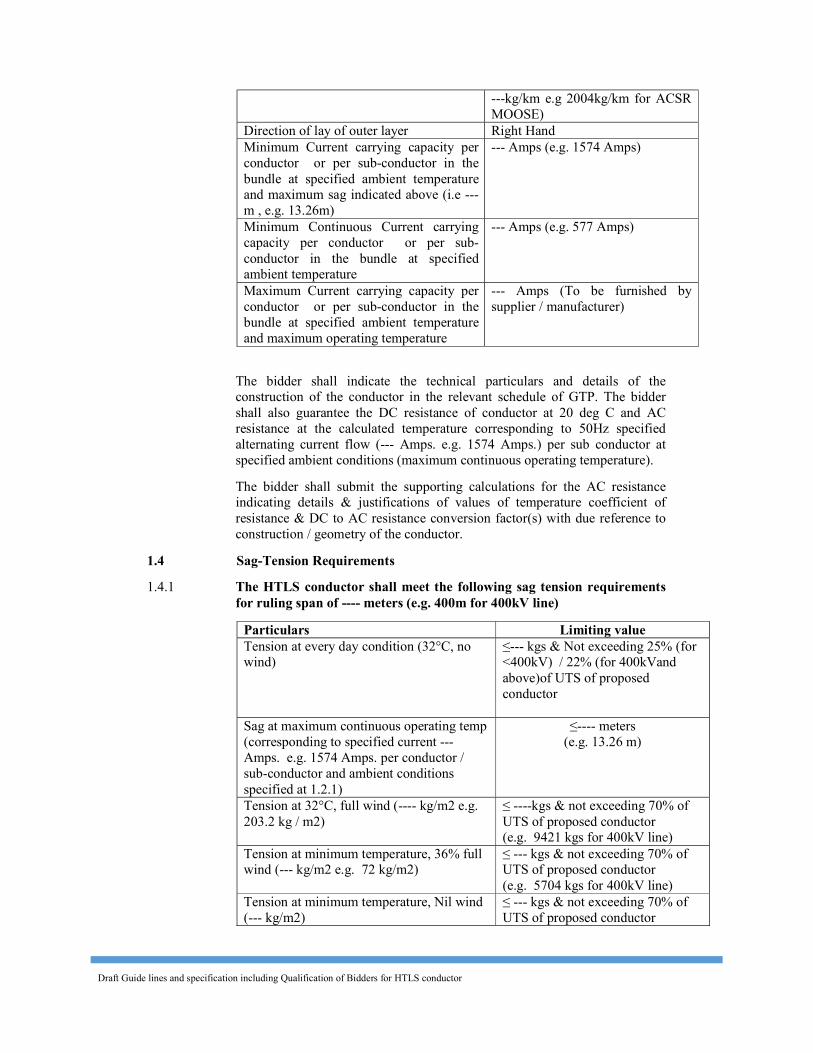
1. 3 Technical Particulars of HTLS Conductor The HTLS conductor shall meet the following minimum requirements:
Overall diameter of complete conductor Not exceeding existing conductor overall diameter (-- mm e.g. 31.77mm for 400kV line) and Not less than (---- mm e.g. 28.62 mm)
Approx. mass of complete conductor (kg/km)
Less than or equal to existing conductor weight per unit length (--
Draft Guide lines and specification including Qualification of Bidders for HTLS conductor
---kg/km e.g 2004kg/km for ACSR MOOSE)
Direction of lay of outer layer Right Hand Minimum Current carrying capacity per conductor or per sub-conductor in the bundle at specified ambient temperature and maximum sag indicated above (i.e --- m , e.g. 13.26m)
--- Amps (e.g. 1574 Amps)
Minimum Continuous Current carrying capacity per conductor or per sub-conductor in the bundle at specified ambient temperature
--- Amps (e.g. 577 Amps)
Maximum Current carrying capacity per conductor or per sub-conductor in the bundle at specified ambient temperature and maximum operating temperature
--- Amps (To be furnished by the supplier / manufacturer)
The bidder shall indicate the technical particulars and details of the
construction of the conductor in the relevant schedule of GTP. The bidder shall also guarantee the DC resistance of conductor at 20 deg C and AC resistance at the calculated temperature corresponding to 50Hz specified alternating current flow (--- Amps. e.g. 1574 Amps.) per sub conductor at specified ambient conditions (maximum continuous operating temperature).
The bidder shall submit the supporting calculations for the AC resistance indicating details & justifications of values of temperature coefficient of resistance & DC to AC resistance conversion factor(s) with due reference to construction / geometry of the conductor.
1.4 Sag-Tension Requirements 1.4.1 The HTLS conductor shall meet the following sag tension requirements
for ruling span of ---- meters (e.g. 400m for 400kV line) Particulars Limiting value Tension at every day condition (32°C, no wind)
≤--- kgs & Not exceeding 25% (for <400kV) / 22% (for 400kVand above)of UTS of proposed conductor
Sag at maximum continuous operating temp (corresponding to specified current --- Amps. e.g. 1574 Amps. per conductor / sub-conductor and ambient conditions specified at 1.2.1)
≤---- meters (e.g. 13.26 m)
Tension at 32°C, full wind (---- kg/m2 e.g. 203.2 kg / m2)
≤ ----kgs & not exceeding 70% of UTS of proposed conductor (e.g. 9421 kgs for 400kV line)
Tension at minimum temperature, 36% full wind (--- kg/m2 e.g. 72 kg/m2)
≤ --- kgs & not exceeding 70% of UTS of proposed conductor (e.g. 5704 kgs for 400kV line)
Tension at minimum temperature, Nil wind (--- kg/m2)
≤ --- kgs & not exceeding 70% of UTS of proposed conductor
Draft Guide lines and specification including Qualification of Bidders for HTLS conductor
Sag-Tension calculations at various conditions mentioned above shall be submitted along with the bid. These calculations shall also include calculations for determination of transition / knee point temperature. The bidder shall also furnish sag & tensions under no wind for various temperatures starting from 0 deg C to maximum continuous operating temperature in steps of 5 degC .
1.4.2 After award of the contract, the Supplier shall submit Sag-Tension
calculations corresponding to various conditions given above for all the spans as per detailed survey and spans ranging from 100 m to 1100 m in intervals of 50 m.
1.4.3 Besides above, the Supplier shall also furnish details of creep characteristics in respect of HTLS conductor based on laboratory investigations/ experimentation (creep test as per IEE1138 or IEC 61395) conducted on similar type of conductor and shall indicate creep strain values corresponding to 1 month, 6 months, 1 year 10 years & 20 years creep at everyday tension & at maximum continuous operating temperature
1.5 Workmanship 1.5.1 All the conductor strands shall be smooth, uniform and free from all
imperfections, such as spills and splits, cracks, die marks, scratches, abrasions, rust etc.
1.5.2 The finished conductor shall be smooth, compact, uniform and free from all imperfections including kinks (protusion of wires), wire cross over, over riding, looseness (wire being dislocated by finger/hand pressure and/or unusual bangle noise on tapping), material inclusions, white rust, powder formation or black spot (on account of reaction with trapped rain water etc.), dirt, grit etc.
1.6 Joints in Wires 1.6.1 Aluminium Alloy Wires 1.6.1.1 During stranding, no Aluminium Alloy wire welds shall be made for the
purpose of achieving the required conductor length. 1.6.1.2 No joints shall be permitted in the individual wires in the outer most layer of
the finished conductor. However, joints are permitted in the inner layer(s) of the conductor unavoidably broken during stranding provided such breaks are not associated with either inherently defective wire or with the use of short lengths of Aluminium Alloy wires. Such joints shall not be more than four (4) per conductor length and shall not be closer than 15 meters from joint in the same wire or in any other Aluminium Alloy wire of the completed conductor. A record of such joints for each individual length of the conductor shall be maintained by The Contractor for Owners review.
1.6.1.3 Joints shall be made by cold pressure butt welding and shall withstand a stress of not less than the breaking strength of individual strand guaranteed.
1.6.2 Core Wires There shall be no joint of any kind in the finished wire entering into the
manufacture of the strand. There shall also be no joints or splices in any length of the completed stranded core
Draft Guide lines and specification including Qualification of Bidders for HTLS conductor
1.7 Tolerances Manufacturing tolerances on the dimensions to the extent of one percent (+/-
1%) shall be permitted for individual strands and the complete conductor. 1.8 Materials The materials used for construction of the conductor shall be such that the
conductor meets the specified technical and performance requirements. 1.8.1 Outer layer 1.8.1.1 The material of outer layer of HTLS conductor shall be of high temperature
resistant aluminum alloy added with zirconium or any other suitable element(s) etc. to electrolytic aluminium having purity not less than 99.5% and a copper content not exceeding 0.04%. The strands shall be manufactured through appropriate manufacturing process to ensure consistent electrical mechanical and metallurgical properties under continuous high temperature operation. Bidder shall guarantee the chemical composition in the schedule GTP of BPS and also furnish description of the manufacturing process in the Bid.
1.8.1.3 In case of fully annealed type (0 tempered) alluminium / alloy strands trapezoidal /Z-shaped wire shall only be accepted.
1.8.3 Core The core wire strand(s) shall be of galvanized steel wires/ aluminium clad
steel wires / Zinc – 5% Aluminium – Misch metal alloy coated invar wire / galvanized invar wires/ aluminium clad invar wires/ composite materials etc and shall have properties conforming to the technical performance requirements of the finished conductor. Bidder shall furnish properties and composition of the core wire strand(s)in the schedule GTP of BPS.
The zinc used for galvanizing in case of steel /invar core shall be electrolytic High Grade Zinc of 99.95% purity. It shall conform to and satisfy all the requirements of IS:209. The minimum mass of zinc coating shall be as per requirements of Class-1 coating as per IEC-888. Zinc – 5% Aluminium – Misch metal alloy coating if used, shall conform to all requirements of ASTM B803 / B 958.
The aluminium cladding of invar/ steel wires shall be with aluminum having purity not less than 99.5 % and shall be thoroughly bonded to the core wire strand(s). The minimum thickness of aluminium cladding shall be 0.07mm to achieve a minimum conductivity of 14% of IACS.
Where composite material for core is offered, the materials shall be of such proven quality that its properties are not adversely influenced by the normal operating conditions of a ---- kV transmission line in tropical environment conditions as experienced by the existing line. The bidder shall provide adequate details including specifications/test reports/operating experience details/performance certificates etc. in support of the suitability of the offered materials.
1.9 Conductor Length 1.9.1 After survey of the involved section of the line by tower contractor, the tower
schedules, section lengths, special crossing etc. shall be finalized by the supplier/ shall be furnished to the supplier. The supplier shall determine the
Draft Guide lines and specification including Qualification of Bidders for HTLS conductor
most appropriate individual conductor lengths to be manufactured & supplied keeping in view tower schedules, section lengths, special crossings etc. and the drum schedules shall be submitted to Owner for review & approval.
1.9.2 The standard length of the conductor shall be indicated in the guaranteed technical particulars of offer. A tolerance of +/-5% on the standard length offered by the Bidder shall be permitted.
1.9.3 The bidder shall also indicate the maximum single length of HTLS Conductor, he can manufacture in the guaranteed technical particulars of offer. Such length of conductor may be required for special stretches like river crossing etc.
1.10 Evaluation of Ohmic Losses & Differential Price Loading 1.10.1 Based on the conductor parameters guaranteed by the bidders, average ohmic
losses for different type of conductors offered by the bidders shall be calculated as per the following formula:
Average Ohmic loss (kW) = Loss Load Factor X Line Length X No. of sub conductors X (Continuous operating current) 2 X AC Resistance corresponding to continuous operating current
For Example: Considering twin bundle conductor per phase, loss load factor = 0. 3, continuous operating current of 577 Amp;
Average Ohmic loss (kW) = 0.3 x 178.5 x 2 x 357 x (577)2 x Rac/1000 = 3.5657 X 10⁴ X Rac
Where Rac is the AC resistance per km guaranteed by the bidder at temperature corresponding to the continuous operating current of 577 A under normal condition.
Differential price evaluation for the conductors offered by the bidders shall be carried out considering the average ohmic losses calculated as above and considering Rs.------------- per kW.
The best parameter of loss (lowest ohmic loss for conductor) corresponding to lowest AC resistance quoted among bidders by any technically responsive and qualified bidder shall be taken as basis and that quoted by the particular
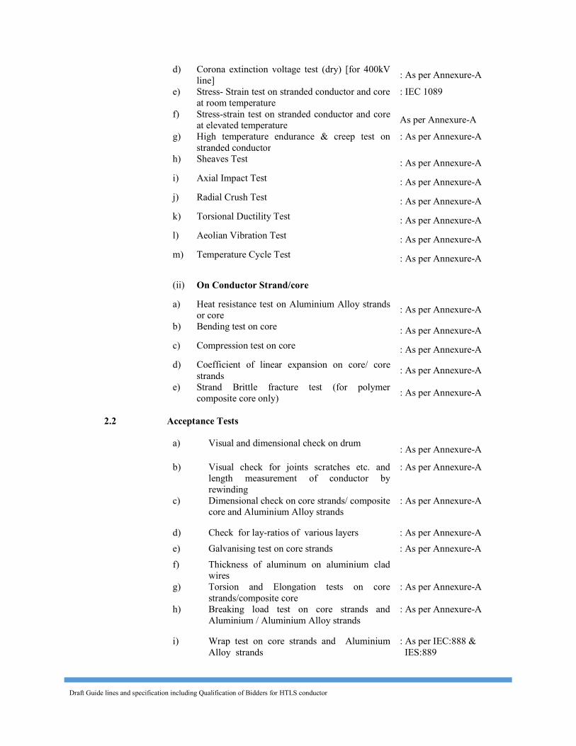
2.0 Tests and Standards 2.1 Type Tests 2.1.1 Type Tests on Stranded Conductor/ Stranded wire The following tests shall be conducted once on sample/samples of conductor
from each manufacturing facility: (i) On complete Conductor a) DC resistance test on stranded conductor : As per Annexure-A b) UTS test on stranded conductor : As per Annexure-A c) Radio interference voltage test (dry) [for 400kV
line] : As per Annexure-A
Draft Guide lines and specification including Qualification of Bidders for HTLS conductor
d) Corona extinction voltage test (dry) [for 400kV line] : As per Annexure-A
e) Stress- Strain test on stranded conductor and core at room temperature
: IEC 1089
f) Stress-strain test on stranded conductor and core at elevated temperature As per Annexure-A
g) High temperature endurance & creep test on stranded conductor
: As per Annexure-A
h) Sheaves Test : As per Annexure-A i) Axial Impact Test : As per Annexure-A j) Radial Crush Test : As per Annexure-A k) Torsional Ductility Test : As per Annexure-A l) Aeolian Vibration Test : As per Annexure-A m) Temperature Cycle Test : As per Annexure-A
(ii) On Conductor Strand/core a) Heat resistance test on Aluminium Alloy strands
or core : As per Annexure-A b) Bending test on core : As per Annexure-A c) Compression test on core : As per Annexure-A d) Coefficient of linear expansion on core/ core
strands : As per Annexure-A e) Strand Brittle fracture test (for polymer
composite core only) : As per Annexure-A 2.2 Acceptance Tests
a) Visual and dimensional check on drum : As per Annexure-A b) Visual check for joints scratches etc. and
length measurement of conductor by rewinding
: As per Annexure-A
c) Dimensional check on core strands/ composite core and Aluminium Alloy strands
: As per Annexure-A
d) Check for lay-ratios of various layers : As per Annexure-A e) Galvanising test on core strands : As per Annexure-A f) Thickness of aluminum on aluminium clad
wires
g) Torsion and Elongation tests on core strands/composite core
: As per Annexure-A h) Breaking load test on core strands and
Aluminium / Aluminium Alloy strands : As per Annexure-A
i) Wrap test on core strands and Aluminium Alloy strands
: As per IEC:888 & IES:889
Draft Guide lines and specification including Qualification of Bidders for HTLS conductor
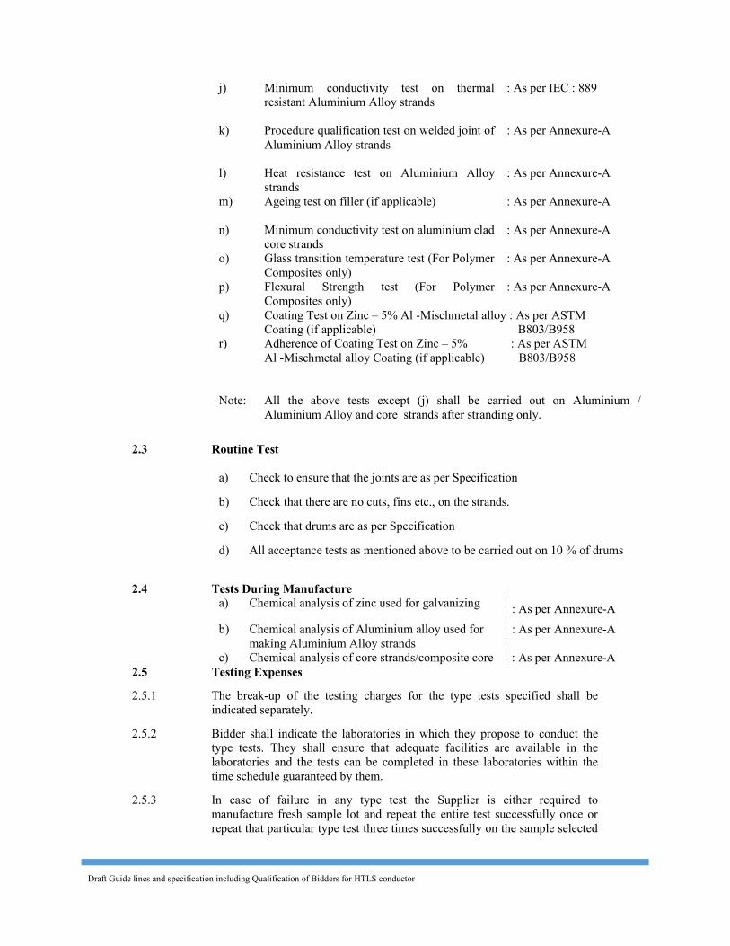
j) Minimum conductivity test on thermal resistant Aluminium Alloy strands
: As per IEC : 889
k) Procedure qualification test on welded joint of Aluminium Alloy strands
: As per Annexure-A
l) Heat resistance test on Aluminium Alloy strands
: As per Annexure-A m) Ageing test on filler (if applicable)
: As per Annexure-A
n) Minimum conductivity test on aluminium clad core strands
: As per Annexure-A o) Glass transition temperature test (For Polymer
Composites only) : As per Annexure-A
p) Flexural Strength test (For Polymer Composites only)
: As per Annexure-A
q) r)
Coating Test on Zinc – 5% Al -Mischmetal alloy : As per ASTM Coating (if applicable) B803/B958 Adherence of Coating Test on Zinc – 5% : As per ASTM Al -Mischmetal alloy Coating (if applicable) B803/B958
Note: All the above tests except (j) shall be carried out on Aluminium / Aluminium Alloy and core strands after stranding only.
2.3 Routine Test
a) Check to ensure that the joints are as per Specification b) Check that there are no cuts, fins etc., on the strands. c) Check that drums are as per Specification d) All acceptance tests as mentioned above to be carried out on 10 % of drums
2.4 Tests During Manufacture a) Chemical analysis of zinc used for galvanizing : As per Annexure-A
b) Chemical analysis of Aluminium alloy used for making Aluminium Alloy strands
: As per Annexure-A c) Chemical analysis of core strands/composite core : As per Annexure-A
2.5 Testing Expenses 2.5.1 The break-up of the testing charges for the type tests specified shall be
indicated separately. 2.5.2 Bidder shall indicate the laboratories in which they propose to conduct the
type tests. They shall ensure that adequate facilities are available in the laboratories and the tests can be completed in these laboratories within the time schedule guaranteed by them.
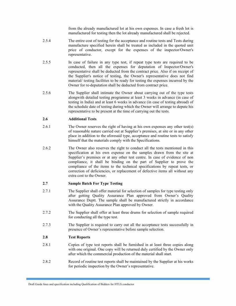
2.5.3 In case of failure in any type test the Supplier is either required to manufacture fresh sample lot and repeat the entire test successfully once or repeat that particular type test three times successfully on the sample selected
Draft Guide lines and specification including Qualification of Bidders for HTLS conductor
from the already manufactured lot at his own expenses. In case a fresh lot is manufactured for testing then the lot already manufactured shall be rejected.
2.5.4 The entire cost of testing for the acceptance and routine tests and Tests during manufacture specified herein shall be treated as included in the quoted unit price of conductor, except for the expenses of the inspector/Owner's representative.
2.5.5 In case of failure in any type test, if repeat type tests are required to be conducted, then all the expenses for deputation of Inspector/Owner's representative shall be deducted from the contract price. Also if on receipt of the Supplier's notice of testing, the Owner's representative does not find material/ testing facilities to be ready for testing the expenses incurred by the Owner for re-deputation shall be deducted from contract price.
2.5.6 The Supplier shall intimate the Owner about carrying out of the type tests alongwith detailed testing programme at least 3 weeks in advance (in case of testing in India) and at least 6 weeks in advance (in case of testing abroad) of the schedule date of testing during which the Owner will arrange to depute his representative to be present at the time of carrying out the tests.
2.6 Additional Tests 2.6.1 The Owner reserves the right of having at his own expenses any other test(s)
of reasonable nature carried out at Supplier’s premises, at site or in any other place in addition to the aforesaid type, acceptance and routine tests to satisfy himself that the materials comply with the Specifications.
2.6.2 The Owner also reserves the right to conduct all the tests mentioned in this specification at his own expense on the samples drawn from the site at Supplier’s premises or at any other test centre. In case of evidence of non compliance, it shall be binding on the part of Supplier to prove the compliance of the items to the technical specifications by repeat tests, or correction of deficiencies, or replacement of defective items all without any extra cost to the Owner.
2.7 Sample Batch For Type Testing 2.7.1 The Supplier shall offer material for selection of samples for type testing only
after getting Quality Assurance Plan approved from Owner’s Quality Assurance Deptt. The sample shall be manufactured strictly in accordance with the Quality Assurance Plan approved by Owner.
2.7.2 The Supplier shall offer at least three drums for selection of sample required for conducting all the type test.
2.7.3 The Supplier is required to carry out all the acceptance tests successfully in presence of Owner’s representative before sample selection.
2.8 Test Reports 2.8.1 Copies of type test reports shall be furnished in at least three copies along
with one original. One copy will be returned duly certified by the Owner only after which the commercial production of the material shall start.
2.8.2 Record of routine test reports shall be maintained by the Supplier at his works for periodic inspection by the Owner’s representative.
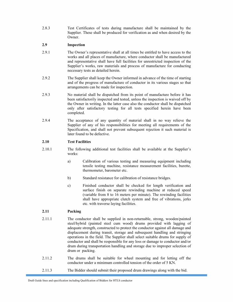
Draft Guide lines and specification including Qualification of Bidders for HTLS conductor
2.8.3 Test Certificates of tests during manufacture shall be maintained by the Supplier. These shall be produced for verification as and when desired by the Owner.
2.9 Inspection 2.9.1 The Owner’s representative shall at all times be entitled to have access to the
works and all places of manufacture, where conductor shall be manufactured and representative shall have full facilities for unrestricted inspection of the Supplier’s works, raw materials and process of manufacture for conducting necessary tests as detailed herein.
2.9.2 The Supplier shall keep the Owner informed in advance of the time of starting and of the progress of manufacture of conductor in its various stages so that arrangements can be made for inspection.
2.9.3 No material shall be dispatched from its point of manufacture before it has been satisfactorily inspected and tested, unless the inspection is waived off by the Owner in writing. In the latter case also the conductor shall be dispatched only after satisfactory testing for all tests specified herein have been completed.
2.9.4 The acceptance of any quantity of material shall in no way relieve the Supplier of any of his responsibilities for meeting all requirements of the Specification, and shall not prevent subsequent rejection it such material is later found to be defective.
2.10 Test Facilities 2.10.1 The following additional test facilities shall be available at the Supplier’s
works: a) Calibration of various testing and measuring equipment including
tensile testing machine, resistance measurement facilities, burette, thermometer, barometer etc.
b) Standard resistance for calibration of resistance bridges. c) Finished conductor shall be checked for length verification and
surface finish on separate rewinding machine at reduced speed (variable from 8 to 16 meters per minute). The rewinding facilities shall have appropriate clutch system and free of vibrations, jerks etc. with traverse laying facilities.
2.11 Packing 2.11.1 The conductor shall be supplied in non-returnable, strong, wooden/painted
steel/hybrid (painted steel cum wood) drums provided with lagging of adequate strength, constructed to protect the conductor against all damage and displacement during transit, storage and subsequent handling and stringing operations in the field. The Supplier shall select suitable drums for supply of conductor and shall be responsible for any loss or damage to conductor and/or drum during transportation handling and storage due to improper selection of drum or packing.
2.11.2 The drums shall be suitable for wheel mounting and for letting off the conductor under a minimum controlled tension of the order of 5 KN.
2.11.3 The Bidder should submit their proposed drum drawings along with the bid.
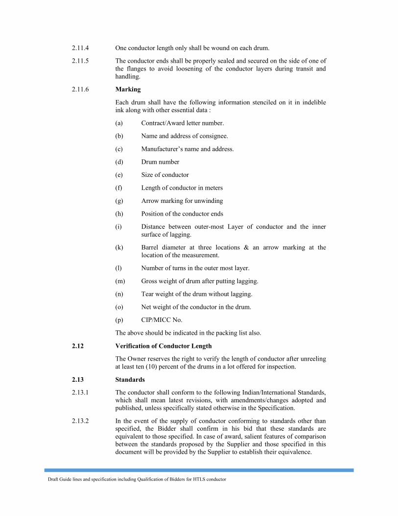
Draft Guide lines and specification including Qualification of Bidders for HTLS conductor
2.11.4 One conductor length only shall be wound on each drum. 2.11.5 The conductor ends shall be properly sealed and secured on the side of one of
the flanges to avoid loosening of the conductor layers during transit and handling.
2.11.6 Marking Each drum shall have the following information stenciled on it in indelible
ink along with other essential data : (a) Contract/Award letter number. (b) Name and address of consignee. (c) Manufacturer’s name and address. (d) Drum number (e) Size of conductor (f) Length of conductor in meters (g) Arrow marking for unwinding (h) Position of the conductor ends (i) Distance between outer-most Layer of conductor and the inner
surface of lagging. (k) Barrel diameter at three locations & an arrow marking at the
location of the measurement. (l) Number of turns in the outer most layer. (m) Gross weight of drum after putting lagging. (n) Tear weight of the drum without lagging. (o) Net weight of the conductor in the drum. (p) CIP/MICC No. The above should be indicated in the packing list also. 2.12 Verification of Conductor Length The Owner reserves the right to verify the length of conductor after unreeling
at least ten (10) percent of the drums in a lot offered for inspection. 2.13 Standards 2.13.1 The conductor shall conform to the following Indian/International Standards,
which shall mean latest revisions, with amendments/changes adopted and published, unless specifically stated otherwise in the Specification.
2.13.2 In the event of the supply of conductor conforming to standards other than specified, the Bidder shall confirm in his bid that these standards are equivalent to those specified. In case of award, salient features of comparison between the standards proposed by the Supplier and those specified in this document will be provided by the Supplier to establish their equivalence.
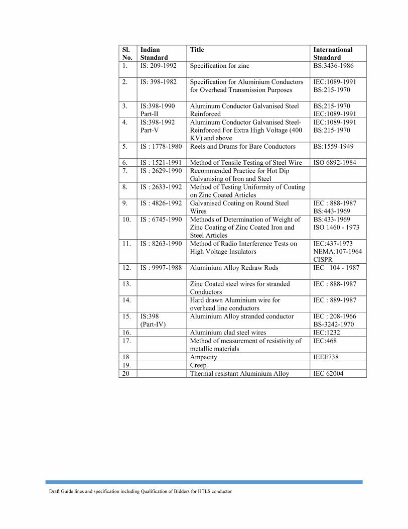
Draft Guide lines and specification including Qualification of Bidders for HTLS conductor
Sl. No.
Indian Standard
Title International Standard
1. IS: 209-1992 Specification for zinc BS:3436-1986
2. IS: 398-1982 Specification for Aluminium Conductors for Overhead Transmission Purposes
IEC:1089-1991 BS:215-1970
3. IS:398-1990 Part-II
Aluminum Conductor Galvanised Steel Reinforced
BS;215-1970 IEC:1089-1991
4. IS:398-1992 Part-V
Aluminum Conductor Galvanised Steel- Reinforced For Extra High Voltage (400 KV) and above
IEC:1089-1991 BS:215-1970
5. IS : 1778-1980 Reels and Drums for Bare Conductors BS:1559-1949
6. IS : 1521-1991 Method of Tensile Testing of Steel Wire ISO 6892-1984 7. IS : 2629-1990 Recommended Practice for Hot Dip
Galvanising of Iron and Steel
8. IS : 2633-1992 Method of Testing Uniformity of Coating on Zinc Coated Articles
9. IS : 4826-1992 Galvanised Coating on Round Steel
Wires IEC : 888-1987 BS:443-1969
10. IS : 6745-1990 Methods of Determination of Weight of Zinc Coating of Zinc Coated Iron and Steel Articles
BS:433-1969 ISO 1460 - 1973
11. IS : 8263-1990 Method of Radio Interference Tests on High Voltage Insulators
IEC:437-1973 NEMA:107-1964 CISPR
12. IS : 9997-1988 Aluminium Alloy Redraw Rods IEC 104 - 1987
13. Zinc Coated steel wires for stranded Conductors
IEC : 888-1987
14. Hard drawn Aluminium wire for overhead line conductors
IEC : 889-1987 15. IS:398
(Part-IV) Aluminium Alloy stranded conductor IEC : 208-1966
BS-3242-1970 16. Aluminium clad steel wires IEC:1232 17. Method of measurement of resistivity of
metallic materials IEC:468
18 Ampacity IEEE738 19. Creep 20 Thermal resistant Aluminium Alloy IEC 62004
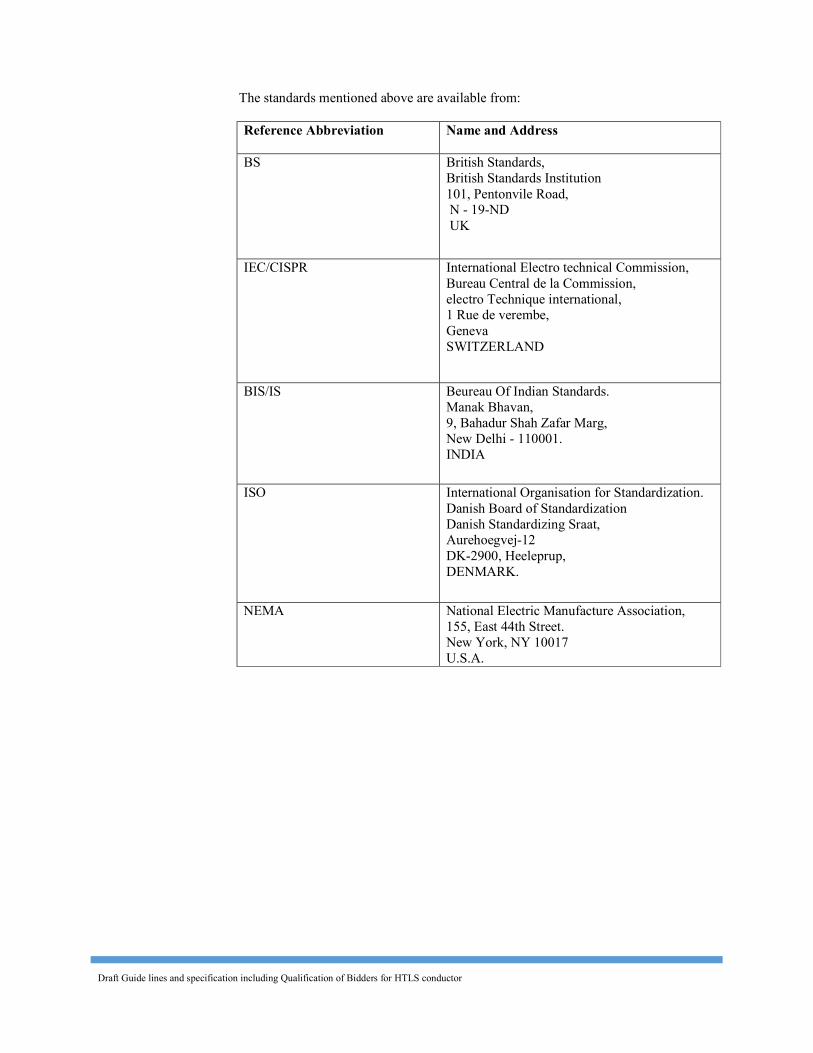
Draft Guide lines and specification including Qualification of Bidders for HTLS conductor
The standards mentioned above are available from:
Reference Abbreviation
Name and Address BS British Standards,
British Standards Institution 101, Pentonvile Road, N - 19-ND UK
IEC/CISPR International Electro technical Commission, Bureau Central de la Commission, electro Technique international, 1 Rue de verembe, Geneva SWITZERLAND
BIS/IS Beureau Of Indian Standards. Manak Bhavan, 9, Bahadur Shah Zafar Marg, New Delhi - 110001. INDIA
ISO International Organisation for Standardization. Danish Board of Standardization Danish Standardizing Sraat, Aurehoegvej-12 DK-2900, Heeleprup, DENMARK.
NEMA National Electric Manufacture Association, 155, East 44th Street. New York, NY 10017 U.S.A.
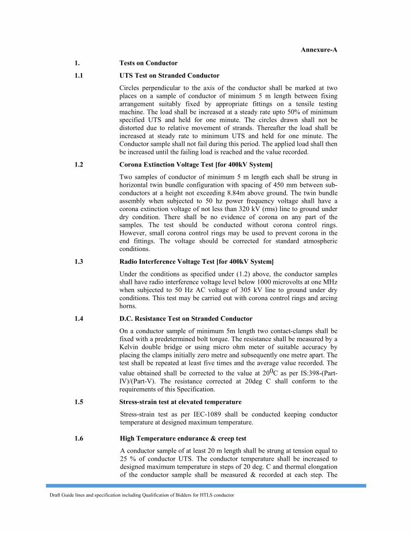
Draft Guide lines and specification including Qualification of Bidders for HTLS conductor
Annexure-A 1. Tests on Conductor 1.1 UTS Test on Stranded Conductor Circles perpendicular to the axis of the conductor shall be marked at two
places on a sample of conductor of minimum 5 m length between fixing arrangement suitably fixed by appropriate fittings on a tensile testing machine. The load shall be increased at a steady rate upto 50% of minimum specified UTS and held for one minute. The circles drawn shall not be distorted due to relative movement of strands. Thereafter the load shall be increased at steady rate to minimum UTS and held for one minute. The Conductor sample shall not fail during this period. The applied load shall then be increased until the failing load is reached and the value recorded.
1.2 Corona Extinction Voltage Test [for 400kV System] Two samples of conductor of minimum 5 m length each shall be strung in
horizontal twin bundle configuration with spacing of 450 mm between sub-conductors at a height not exceeding 8.84m above ground. The twin bundle assembly when subjected to 50 hz power frequency voltage shall have a corona extinction voltage of not less than 320 kV (rms) line to ground under dry condition. There shall be no evidence of corona on any part of the samples. The test should be conducted without corona control rings. However, small corona control rings may be used to prevent corona in the end fittings. The voltage should be corrected for standard atmospheric conditions.
1.3 Radio Interference Voltage Test [for 400kV System] Under the conditions as specified under (1.2) above, the conductor samples
shall have radio interference voltage level below 1000 microvolts at one MHz when subjected to 50 Hz AC voltage of 305 kV line to ground under dry conditions. This test may be carried out with corona control rings and arcing horns.
1.4 D.C. Resistance Test on Stranded Conductor On a conductor sample of minimum 5m length two contact-clamps shall be
fixed with a predetermined bolt torque. The resistance shall be measured by a Kelvin double bridge or using micro ohm meter of suitable accuracy by placing the clamps initially zero metre and subsequently one metre apart. The test shall be repeated at least five times and the average value recorded. The value obtained shall be corrected to the value at 200C as per IS:398-(Part-IV)/(Part-V). The resistance corrected at 20deg C shall conform to the requirements of this Specification.
1.5 Stress-strain test at elevated temperature Stress-strain test as per IEC-1089 shall be conducted keeping conductor temperature at designed maximum temperature.
1.6 High Temperature endurance & creep test A conductor sample of at least 20 m length shall be strung at tension equal to 25 % of conductor UTS. The conductor temperature shall be increased to designed maximum temperature in steps of 20 deg. C and thermal elongation of the conductor sample shall be measured & recorded at each step. The
Draft Guide lines and specification including Qualification of Bidders for HTLS conductor
temperature shall be held at each step for sufficient duration for stablisation of temperature. Further, the temperature of the conductor shall be maintained at maximum continuous operating temperature (+10 Deg. C) for 1000 hours. The elongation/creep strain of the conductor during this period shall be measured and recorded at end of 1 hour, 10 hour, 100 hour and subsequently every 100 hour upto 1000 hours time period. After completion of the above, the conductor sample shall be subjected to UTS test as mentioned above at clause 1.1 of Annexure-A. The supplier shall plot the thermal elongation with temperature. The supplier shall furnish details of creep characteristic in respect of the conducted based on laboratory test and other laboratory investigations/ experimental conducted on similar type of conductor and shall indicate creep strain values corresponding to 1 month, 6 month, 1 year, 10 year & 20 year creep at everyday tension & continuous designed temperature.
1.7 Sheaves Test
The conductor sample of minimum length of 35 meter shall be tensioned at 22 % of the UTS and shall be passed through pulleys having diameter of 32 times that of the conductor with angle of 20 deg. between the pulleys. The conductor shall be passed over the pulleys 36 times a speed of 2 m/sec. After this test UTS test on the conductor shall be carried out.
1.8 Axial Impact Test
The conductor sample shall be suspended vertically and load applied by dropping a 650 Kg from an elevation of 4 meters above the sample. The impact velocity shall be not be less than 8 m/sec. with an intial pre-tension of 200 kgs. The curve for load vs time shall be recorded and recorded load of failure for core shall not be less than UTS of core.
1.9 Radial Crush Test
A section of conductor is to be crushed between two six inch steel platens. Load shall be held at 350 Kgs for 1 minute and then released. All the strands shall be subsequently disassembled and tensile tested. All the strands shall exhibit full strength retention
1.10 Torsional Ductility Test
The conductor shall be loaded to 25% of UTS and than rotated in increasing steps of +/-180 deg. The conductor shall withstand atleast 16 such rotation.
1.11 Aeolian Vibration Test The conductor and supporting hardware shall be loaded to _25% of RTS. A dynamometer, load cell, calibrated beam or other device shall be used to measure the conductor tension. Some means should be provided to maintain constant tension to allow for temperature fluctuations during the testing. The overall span between system terminations shall be a minimum of 30 m. The span shall be supported at a height such that the static sag angle of the cable to horizontal is (1.5 + 0.5) deg in the active span. Means shall be provided for
Draft Guide lines and specification including Qualification of Bidders for HTLS conductor
measuring and monitoring the mid-loop (antinode) vibration amplitude at a free loop, not a support loop. An electronically controlled shaker shall be used to excite the conductor in the vertical plane. The shaker armature shall be securely fastened to the conductor so it is perpendicular to the conductor in the vertical plane. The shaker should be located in the span to allow for a minimum of six vibration loops between the suspension assembly and the shaker
The test shall be carried out at one or more resonance frequencies (more than 10 Hz) . The amplitude at the antinode point shall be one third of conductor diameter. The assembly shall be vibrated for not less than 10 million cycles without any failure. After the test, the conductor should not exhibit any damage (broken strands). The conductor shall be tested to demonstrate that it retains at least 95% RTS.
1.12 Temperature Cycle Test The purpose of this test is verification of degradation characteristics of metallic and non-metallic material when subjected to thermal cycling temperature cycling can create large internal stresses due to thermal expansion mismatch between constituents. Test Methods:- - Mechanical tension, 20 % RBS, marks on the conductor at the edge of
the conductor - 100 cycles from room temperature up to maximum temperature. Hold at maximum temperature + 2.5 deg. C (duration of a cycle, 1 hour or so, non included cooling) - Mechanical tension up to 70 % RBS at room temperature during 24 H and release to 20 % RBS. - This cycling test shall be repeated 5 times. - During the test, temperature of connectors, conductor and resistance are recorded according to ANSI C 119. - A breaking load test is applied at the end of the test. Conductor strength has to be higher than 95 % RBS.
1.13 Heat Resistance test on Aluminium Alloy wire Breaking load test as per clause 1.21 above shall be carried out before and
after heating the sample in uniform heat furnace at following temperature for one hour. The breaking strength of the wire after heating shall not be less than the 90% of the breaking strength before heating:-
Maximum continuous operating temperature of the conductor
Test Temperature
Upto 150 deg. C 230 degC (+5/-3 degC) More than 150 deg. C & upto 210 deg. C 280 degC (+5/-3 degC) More than 210 deg. C & upto 230 deg. C 400 degC (+5/-3 degC)
1.14 Bending test on aluminium clad core strand
Draft Guide lines and specification including Qualification of Bidders for HTLS conductor
A sample of aluminium clad invar strand measuring 30 cm in length shall be subject to bending with help of a vise. The vised length of wire should be 5 cm and radius of bend 4.8 mm. The bending should be first 90 degrees left and 90 degree right. After this operation the strand should cut at the bending point. There should be no separation of core and aluminium at the bending point after this operation.
1.15 Compression test on aluminium clad strand A sample of aluminium clad core strand 10 mm in length is to be compressed by a plate with a load of 3600 kgs. The aluminium and core strand should not break.
1.16 Coefficient of linear expansion for core/core strands
The temperature and elongation on a sample shall be continuously measured and recorded at interval of approximately 15 degree C from 15 degree C to maximum continuous operating temperature corresponding to rated current(1228 A) by changing the temperature by suitable means. Coefficient of linear expansion shall be determined from the measured results.
1.17 Strand Brittle fracture test (for polymer composite core only) The sample shall be tensioned with simultaneous application of 1N-HNO3 acid directly in contact with naked polymer composite core. The contact length of acid shall not be less than 40mm and thickness around the core not less than 10mm.The rod shall withstand 80% of SML for 96 hours.
1.18 Visual and Dimensional Check on Drums The drums shall be visually and dimensionally checked to ensure that they
conform to the approved drawings. 1.19 Visual Check for Joints, Scratches etc. Conductor drums shall be rewound in the presence of the Owner. The Owner
shall visually check for scratches, joints etc. and that the conductor generally conform to the requirements of this Specification. Ten percent (10%) drums from each lot shall be rewound in the presence of the Owner's representative.
1.20 Dimensional Check on Core Strands and Aluminium Alloy Strands The individual strands shall be dimensionally checked to ensure that they
conform to the requirement of this Specification. 1.21 Check for Lay-ratios of Various Layers The lay-ratios of various layers shall be checked to ensure that they conform
to the guaranteed values furnished by the Contractor.
Draft Guide lines and specification including Qualification of Bidders for HTLS conductor
1.22 Galvanising Test The test procedure shall be as specified in IEC : 888. The material shall
conform to the requirements of this Specification. The adherence of zinc shall be checked by wrapping around a mandrel four times the diameter of steel wire.
1.23 Aluminum thickness on aluminum clad wires
The thickness of aluminium of the specimen shall be determined by using suitable electrical indicating instruments operating on the permeameter principle, or direct measurement. Measurements shall be read to three decimal places, and number rounded to two decimal places is considered as measured thickness. For reference purposes, direct measurement shall be used to determine aluminium thickness on specimens taken from the end of the coils.
1.24 Torsion and Elongation Tests on Core Strands/composite core The test procedures shall be as per clause No. 10.3 of IEC 888. In torsion test,
the number of complete twists before fracture shall not be less than 18 on a length equal to 100 times the standard diameter of the strand. In case test sample length is less or more than 100 times the stranded diameter of the strand, the minimum number of twists will be proportioned to the length and if number comes in the fraction then it will be rounded off to next higher whole number. In elongation test, the elongation of the strand shall not be less than 1.5% for a gauge length of 250 mm.
1.25 Breaking load test on Aluminium Alloy & Core strands and D.C
Resistance test on Aluminium Alloy wire The above tests shall be carried out as per IEC: 888/889 and the results shall meet the requirements of the specification.
1.26 Wrap test on Core strands (Applicable for steel/Al clad Steel core only) The wrap test on steel strands shall be meet the requirements of IEC: 888. In case of aluminium clad core wire, the same shall be wraped around a mandel of diameter of five times that of the strand to form a helix of eight turns. The strand shall be unwrapped. No breakage of strand shall have occurred.
1.27 Minimum conductivity test on thermal resistant aluminium alloy strands Resistivity test as per IEC-468/IEC 889 shall be conducted to confirm minimum conductivity as per specification requirement.
1.28 Procedure Qualification test on welded Aluminium Alloy strands. Two Aluminium Alloy wire shall be welded as per the approved qualityplan
and shall be subjected to tensile load. The breaking strength of the welded joint of the wire shall not be less than the guaranteed breaking strength of individual strands.
Draft Guide lines and specification including Qualification of Bidders for HTLS conductor
1.29 Ageing Test on Filler (if applicable) The test shall be done in accordance with Grease drop point test method. The
specimen should be drop as a droplet when kept at a temperature 40 deg. C above designed maximum operating temperature of the conductor for 30 minutes. The temperature shall then be increase till one droplet drops and the temperature recorded.
1.30 Aluminium conductivity test on aluminium clad strand
Resistivity test as per IEC-468 shall be conducted to confirm minimum conductivity as per specification requirement.
1.31 Glass Transition Temperature Test (for polymer composite core only) Test method shall be as per mutually agreed between employer and supplier during detailed engineering.
1.32 Flexural Strength Test (for polymer composite core only) Test method shall be as per mutually agreed between employer and supplier during detailed engineering.
1.33 Chemical Analysis of Aluminium Alloy and Core Samples taken from the Aluminium and core coils/strands shall be
chemically/spectrographically analysed. The same shall be in conformity to the particulars guaranteed by the bidder so as to meet the requirements stated in this Specification.
1.34 Chemical Analysis of Zinc Samples taken from the zinc ingots shall be chemically/ spectrographically
analysed. The same shall be in conformity to the requirements stated in the Specification.
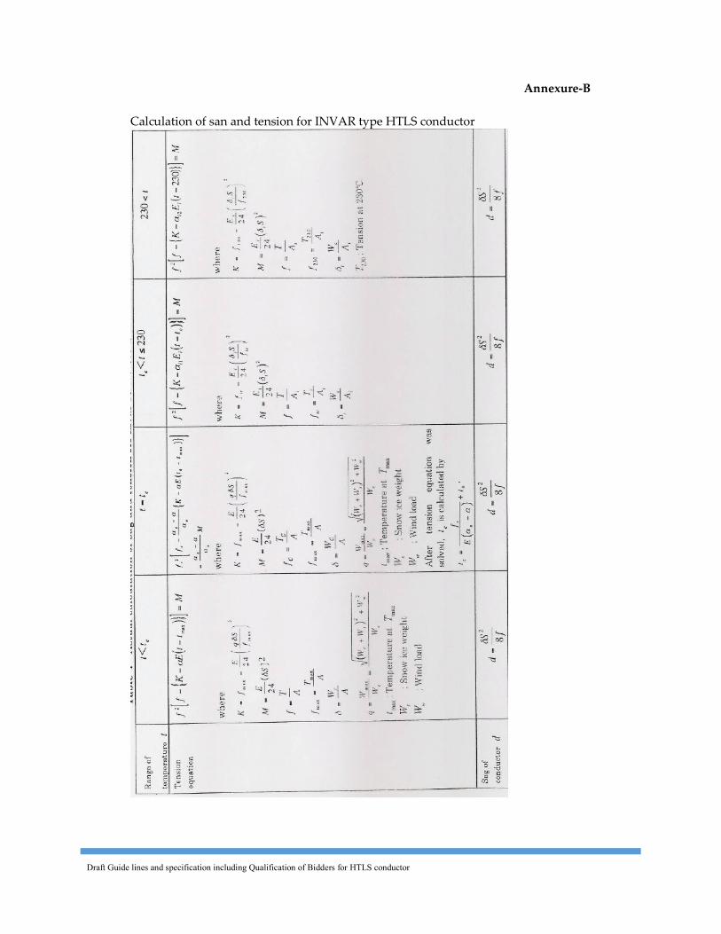
Draft Guide lines and specification including Qualification of Bidders for HTLS conductor
Annexure-B Calculation of san and tension for INVAR type HTLS conductor
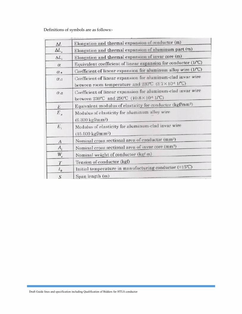
Draft Guide lines and specification including Qualification of Bidders for HTLS conductor
Definitions of symbols are as follows:-

Draft Guide lines and specification including Qualification of Bidders for HTLS conductor
Sample Calculation
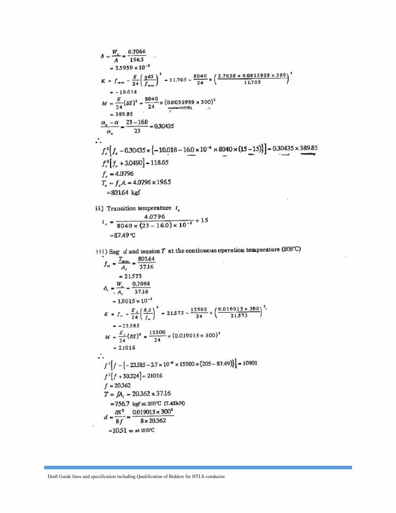
Draft Guide lines and specification including Qualification of Bidders for HTLS conductor
Draft Guide lines and specification including Qualification of Bidders for HTLS conductor
SECTION-V
TECHNICAL SPECIFICATION FOR
HARDWARE FITTINGS ANDACCESSORIES
Draft Guide lines and specification including Qualification of Bidders for HTLS conductor
SECTION - V TECHNICAL SPECIFICATION FOR HARDWARE FITTINGS AND ACCESSORIES
CONTENTS
Clause No. Description Page No.
1.0 Technical Description of Hardware Fittings 2.0 Accessories for Conductor 3.0 Tests and Standards
Annexure-A Annexure-B
Draft Guide lines and specification including Qualification of Bidders for HTLS conductor
SECTION - V TECHNICAL SPECIFICATION FOR HARDWARE FITTINGS AND ACCESSORIES 1. Technical Description of Hardware Fittings 1.1 General This section details technical particulars of fittings viz. suspension clamps
and compression type dead end clamps for the HTLS Conductor to be supplied by the bidder. Each fitting shall be supplied complete in all respects.
1.2 The fittings shall be suitable for attachment to suspension and tension insulator strings alongwith hardware fittings and shall include 2.5 % extra fasteners and Aluminium filler plugs. The supplier shall be responsible for satisfactory performance of complete conductor system along with fittings offered by them for continuous operation at the designed maximum temperature specified by them for the conductor.
1.3 Corona and RI Performance [for 400kV] Sharp edges and scratches on all the hardware fittings shall be avoided. All
surfaces must be clean, smooth, without cuts and abrasions or projections. The Supplier shall be responsible for satisfactory corona and radio interference performance of the materials offered by him.
1.4 Maintenance 1.4.1 The hardware fittings offered shall be suitable for employment of hot line
maintenance technique so that usual hot line operations can be carried out with ease, speed and safety. The technique adopted for hot line maintenance shall be generally bare hand method & hot stick method.
1.5 Split Pins 1.5.1 Split pins shall be used with bolts & nuts. 1.6 Suspension Assembly 1.6.1 The suspension assembly shall be suitable for the HTLS Conductor, the
bidder intends to supply. The technical details of the conductor shall be as proposed by the bidder.
1.6.2 The suspension assembly shall include either free centre type suspension clamp alongwith standard preformed armour rods or armour grip suspension clamp.
1.6.3 The suspension clamp alongwith standard preformed armour rods set shall be designed to have maximum mobility in any direction and minimum moment of inertia so as to have minimum stress on the conductor in the case of oscillation of the same.
1.6.4 The suspension clamp suitable for various type of Conductor alongwith standard preformed armour rods/armour grip suspension clamp set shall have a slip strength in conformity with relevant Indian/ International standards.
1.6.5 The suspension clamp shall be designed for continuous operation at the temperature specified by the bidder for conductor.
Draft Guide lines and specification including Qualification of Bidders for HTLS conductor
1.6.6 The suspension assembly shall be designed, manufactured and finished to give it a suitable shape, so as to avoid any possibility of hammering between suspension assembly and conductor due to vibration. The suspension assembly shall be smooth without any cuts, grooves, abrasions, projections, ridges or excrescence which might damage the conductor.
1.6.7 The suspension assembly/clamp shall be designed so that it shall minimise the static & dynamic stress developed in the conductor under various loading conditions as well as during wind induced conductor vibrations. It shall also withstand power arcs & have required level of Corona/RIV performance.
1.6.9 Free Centre Type Suspension Clamp For the Free Centre Suspension Clamp seat shall be smoothly rounded and
curved into a bell mouth at the ends. The lip edges shall have rounded bead. There shall be at least two U-bolts for tightening of clamp body and keeper pieces together.
1.6.10 Standard Preformed Armour Rod Set 1.6.10.1 The Preformed Armour Rods Set shall be used to minimise the stress
developed in the sub-conductor due to different static and dynamic loads because of vibration due to wind, slipping of conductor from the suspension clamp as a result of unbalanced conductor tension in adjacent spans and broken wire condition. It shall also withstand power arcs, chafing and abrasion from suspension clamp and localised heating effect due to magnetic power losses from suspension clamps as well as resistance losses of the conductor.
1.6.10.2 The preformed armour rods set shall have right hand lay and the inside diameter of the helics shall be less than the outside diameter of the conductor to have gentle but permanent grip on the conductor. The surface of the armour rod when fitted on the conductor shall be smooth and free from projections, cuts and abrasions etc.
1.6.10.3 The pitch length of the rods shall be determined by the Bidder but shall be less than that of the outer layer of conductor and the same shall be accurately controlled to maintain uniformity and consistently reproducible characteristic wholly independent of the skill of linemen.
1.6.10.4 The length and diameter of each rod shall be furnished by the bidder in the GTP. The tolerance in length of the rods between the longest and shortest rod in complete set should be within the limits specified in relevant Indian/International Standards . The ends of armour rod shall be parrot billed.
1.6.10.5 The length and diameter of each rod shall be specified in the GTP. The tolerance in length of the rods in complete set should be within 13 mm between the longest and shortest rod. The ends of armour rod shall be parrot billed.
1.6.10.6 The number of armour rods in each set shall be supplier’s design to suit HTLS conductor offered Standards. Each rod shall be marked in the middle with paint for easy application on the line.
1.6.10.7 The armour rod shall not loose their resilience even after five applications. 1.6.10.8 The conductivity of each rod of the set shall not be less than 40% of the
conductivity of the International Annealed Copper Standard (IACS).
Draft Guide lines and specification including Qualification of Bidders for HTLS conductor
1.6.11 Armour Grip Suspension Clamp 1.6.11.1 The armour grip suspension clamp shall comprise of retaining strap, support
housing, elastomer inserts with aluminium reinforcements and AGS preformed rod set.
1.6.11.2 Elastomer insert shall be resistant to the effects of temperature up to designed maximum conductor temperature guaranteed by the bidder corresponding to peak current, Ozone, ultraviolet radiations and other atmospheric contaminants likely to be encountered in service. The physical properties of the elastomer shall be of approved standard. It shall be electrically shielded by a cage of AGS performed rod set. The elastomer insert shall be so designed that the curvature of the AGS rod shall follow the contour of the neoprene insert.
1.6.11.3 The supplier shall submit relevant type/performance test certificates as per applicable standard/product specifications for elastomer to confirm suitability of the offered elastomer for the specified application.
1.6.11.4 The AGS preformed rod set shall be as detailed in clause 1.6.10.4 to 1.6.10.7 in general except for the following.
1.6.11.4 The length of the AGS preformed rods shall be such that it shall ensure sufficient slipping strength as detailed under clause 1.6.4 and shall not introduce unfavourable stress on the conductor under all operating conditions. The length of the AGS preformed rods shall be indicated in the GTP.
1.7 Envelope Type Suspension Clamp 1.7.1 The seat of the envelope type suspension clamp shall be smoothly rounded &
suitably curved at the ends. The lip edges shall have rounded bead. There shall be at least two U-bolts for tightening of clamp body and keeper pieces together. Hexagonal bolts and nuts with split-pins shall be used for attachment of the clamp.
1.8 Dead end Assembly 1.8.1 The dead end assembly shall be suitable for the offered HTLS Conductor.
1.8.2 The dead end assembly shall be of compression type with provision for
compressing jumper terminal at one end. The angle of jumper terminal to be mounted (including angle of pad) should be 30° with respect to the vertical line. The area of bearing surface on all the connections shall be sufficient to ensure positive electrical and mechanical contact and avoid local heating due to I2R losses. The resistance of the clamp when compressed on Conductor shall not be more than 75% of the resistance of equivalent length of Conductor.
1.8.3 Die compression areas shall be clearly marked on each dead-end assembly designed for continuous die compressions and shall bear the words ‘COM PRESS FIRST’ suitably inscribed near the point on each assembly where the compression begins. If the dead end assembly is designed for intermittent die compressions it shall bear identification marks ‘COMPRESSION ZONE’ AND ‘NON-COMPRESSION ZONE’ distinctly with arrow marks showing
Draft Guide lines and specification including Qualification of Bidders for HTLS conductor
the direction of compressions and knurling marks showing the end of the zones. Tapered aluminium filler plugs shall also be provided at the line of demarcation between compression & non-compression zone. The letters, number and other markings on the finished clamp shall be distinct and legible. The dimensions of dead end assembly before & after compression alongwith tolerances shall be guaranteed in the relevant schedules of the bid and shall be decided by the manufacturer so as to suit the conductor size & conform to electrical & mechanical requirement stipulated in the specification. These shall be guaranteed in the relevant schedules of bid.
1.8.4 The assembly shall not permit slipping of, damage to, or failure of the complete conductor or any part thereof at a load less than 95% of the ultimate tensile strength of the conductor.
1.8.5 Jumper bolting arrangement between jumper terminal/cone and terminal pad/plate of dead end assembly of tension hardware fittings shall be designed to suit the specification requirement of -----A current and shall conform to the relevant Indian/International standards
1.8.6 For composite core HTLS conductor, dead end assembly shall inter-alia include collets, collet housing, inner sleeve etc., suitable for the offered design of HTLS conductor
1.9 Fasteners: Bolts, Nuts and Washers 1.9.1 All bolts and nuts shall conform to IS 6639. All bolts and nuts shall be
galvanised as per IS 1367 (Part-13)/IS 2629. All bolts and nuts shall have hexagonal heads, the heads being forged out of solid truly concentric, and square with the shank, which must be perfectly straight.
1.9.2 Bolts upto M16 and having length upto 10 times the diameter of the bolt should be manufactured by cold forging and thread rolling process to obtain good and reliable mechanical properties and effective dimensional control. The shear strength of bolt for 5.6 grade should be 310 MPa minimum as per IS 12427. Bolts should be provided with washer face in accordance with IS 1363 (Part-1) to ensure proper bearing.
1.9.3 Nuts should be double chamfered as per the requirement of IS 1363 Part-III 1984. It should be ensured by the manufacturer that nuts should not be over tapped beyond 0.4 mm oversize on effective diameter for size upto M16.
1.9.4 Fully threaded bolts shall not be used. The length of the bolt shall be such that the threaded portion shall not extend into the place of contact of the component parts.
1.9.5 All bolts shall be threaded to take the full depth of the nuts and threaded enough to permit the firm gripping of the component parts but no further. It shall be ensured that the threaded portion of the bolt protrudes not less than 3 mm and not more than 8 mm when fully tightened. All nuts shall fit and tight to the point where shank of the bolt connects to the head.
1.9.6 Flat washers and spring washers shall be provided wherever necessary and shall be of positive lock type. Spring washers shall be electro-galvanised. The thickness of washers shall conform to IS:2016.
1.9.7 The Contractor shall furnish bolt schedules giving thickness of components connected, the nut and the washer and the length of shank and the threaded portion of bolts and size of holes and any other special details of this nature.
Draft Guide lines and specification including Qualification of Bidders for HTLS conductor
1.9.8 To obviate bending stress in bolt, it shall not connect aggregate thickness more than three time its diameter.
1.9.9 Bolts at the joints shall be so staggered that nuts may be tightened with spanners without fouling.
1.9.10 To ensure effective in-process Quality control it is essential that the manufacturer should have all the testing facilities for tests like weight of zinc coating, shear strength, other testing facilities etc, in-house. The manufacturer should also have proper Quality Assurance system which should be in line with the requirement of this specification and IS-.14000 services Quality System standard.
1.9.11 Fasteners of grade higher than 8.8 are not to be used and minimum grade for bolt shall be 5.6.
1.10 Materials The materials of the various components shall be as specified hereunder. The
Bidder shall indicate the material proposed to be used for each and every component of hardware fittings stating clearly the class, grade or alloy designation of the material, manufacturing process & heat treatment details and the reference standards.
1.10.1 The details of materials for different component are listed as in Table No-1. 1.11 Workmanship 1.11.1 All the equipment shall be of the latest design and conform to the best
modern practices adopted in the Extra High Voltage field. The Bidder shall offer only such equipment as guaranteed by him to be satisfactory and suitable for ---kV transmission lines and will give continued good performance. For employer’s review of the offered design of clamps/ fittings, the supplier shall submit document/design details of similar type of clamps/ fittings used in past for similar type of HTLS conductor application
1.11.2 High current, heat rise test shall be conducted by the supplier to determine the maximum temperature achieved in different components of fittings under simulated service condition corresponding to continuous operation of conductor at designed maximum temperature. The material of the components should be suitable for continued good performance corresponding to these maximum temperatures. The supplier shall submit relevant type/performance test certificates as per applicable standards/product specifications to confirm suitability of the offered material.
1.11.3 The design, manufacturing process and quality control of all the materials shall be such as to give the specified mechanical rating, highest mobility, elimination of sharp edges and corners to limit corona and radio-interference, best resistance to corrosion and a good finish.
1.11.4 All ferrous parts including fasteners shall be hot dip galvanised, after all machining has been completed. Nuts may, however, be tapped (threaded) after galvanising and the threads oiled. Spring washers shall be electro galvanised. The bolt threads shall be undercut to take care of the increase in diameter due to galvanising. Galvanising shall be done in accordance with IS 2629 / IS 1367 (Part-13) and shall satisfy the tests
Draft Guide lines and specification including Qualification of Bidders for HTLS conductor
mentioned in IS 2633. Fasteners shall withstand four dips while spring washers shall withstand three dips of one minute duration in the standard Preece test. Other galvanised materials shall have a minimum average coating of zinc equivalent to 600 gm/sq.m., shall be guaranteed to withstand at least six successive dips each lasting one (1) minute under the standard preece test for galvanising.
1.11.5 Before ball fittings are galvanized, all die flashing on the shank and on the bearing surface of the ball shall be carefully removed without reducing the dimensions below the design requirements.
1.11.6 The zinc coating shall be perfectly adherent, of uniform thickness, smooth, reasonably bright, continuous and free from imperfections such as flux, ash rust, stains, bulky white deposits and blisters. The zinc used for galvanising shall be grade Zn 99.95 as per IS:209.
1.11.7 Pin balls shall be checked with the applicable ‚GO‛ gauges in at least two directions. one of which shall be across the line of die flashing, and the other 90o to this line. "NO GO" gauges shall not pass in any direction.
1.11.8 Socket ends, before galvanising, shall be of uniform contour. The bearing surface of socket ends shall be uniform about the entire circumference without depressions of high spots. The internal contours of socket ends shall be concentric with the axis of the fittings as per IS:2486/IEC : 120.
The axis of the bearing surfaces of socket ends shall be coaxial with the axis of the fittings. There shall be no noticeable tilting of the bearing surfaces with the axis of the fittings.
1.11.7 In case of casting, the same shall be free from all internal defects like shrinkage, inclusion, blow holes, cracks etc. Pressure die casting shall not be used for casting of components with thickness more than 5 mm.
1.11.8 All current carrying parts shall be so designed and manufactured that contact resistance is reduced to minimum.
1.11.9 No equipment shall have sharp ends or edges, abrasions or projections and cause any damage to the conductor in any way during erection or during continuous operation which would produce high electrical and mechanical stresses in normal working. The design of adjacent metal parts and mating surfaces shall be such as to prevent corrosion of the contact surface and to maintain good electrical contact under service conditions.
1.11.9 All the holes shall be cylindrical, clean cut and perpendicular to the plane of the material. The periphery of the holes shall be free from burrs.
1.11.10 All fasteners shall have suitable corona free locking arrangement to guard against vibration loosening.
1.11.11 Welding of aluminium shall be by inert gas shielded tungesten arc or inert gas shielded metal arc process. Welds shall be clean, sound, smooth, uniform without overlaps, properly fused and completely sealed. There shall be no cracks, voids incomplete penetration, incomplete fusion, under-cutting or inclusions. Porosity shall be minimised so that mechanical properties of the aluminium alloys are not affected. All welds shall be properly finished as per good engineering practices.
1.12 Bid Drawings
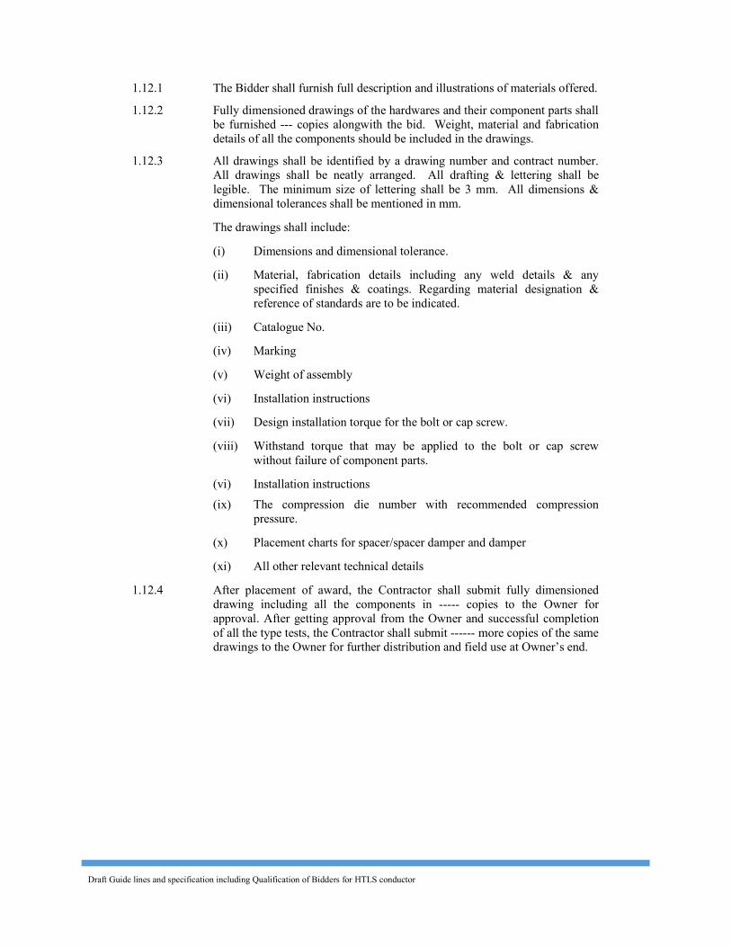
Draft Guide lines and specification including Qualification of Bidders for HTLS conductor
1.12.1 The Bidder shall furnish full description and illustrations of materials offered. 1.12.2 Fully dimensioned drawings of the hardwares and their component parts shall
be furnished --- copies alongwith the bid. Weight, material and fabrication details of all the components should be included in the drawings.
1.12.3 All drawings shall be identified by a drawing number and contract number. All drawings shall be neatly arranged. All drafting & lettering shall be legible. The minimum size of lettering shall be 3 mm. All dimensions & dimensional tolerances shall be mentioned in mm.
The drawings shall include: (i) Dimensions and dimensional tolerance. (ii) Material, fabrication details including any weld details & any
specified finishes & coatings. Regarding material designation & reference of standards are to be indicated.
(iii) Catalogue No. (iv) Marking (v) Weight of assembly (vi) Installation instructions (vii) Design installation torque for the bolt or cap screw. (viii) Withstand torque that may be applied to the bolt or cap screw
without failure of component parts. (vi) Installation instructions (ix) The compression die number with recommended compression
pressure. (x) Placement charts for spacer/spacer damper and damper (xi) All other relevant technical details 1.12.4 After placement of award, the Contractor shall submit fully dimensioned
drawing including all the components in ----- copies to the Owner for approval. After getting approval from the Owner and successful completion of all the type tests, the Contractor shall submit ------ more copies of the same drawings to the Owner for further distribution and field use at Owner’s end.
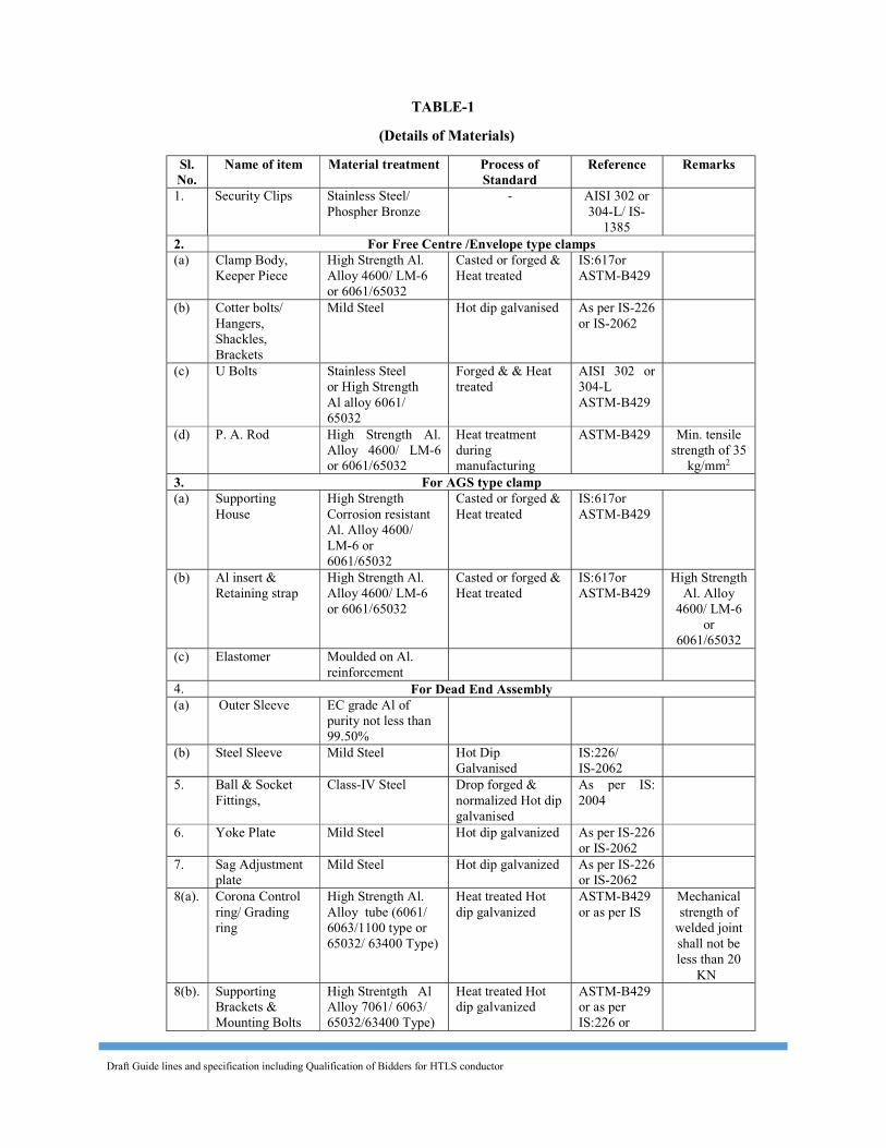
Draft Guide lines and specification including Qualification of Bidders for HTLS conductor
TABLE-1 (Details of Materials)
Sl. No.
Name of item Material treatment Process of Standard
Reference Remarks 1. Security Clips Stainless Steel/
Phospher Bronze - AISI 302 or
304-L/ IS-1385
2. For Free Centre /Envelope type clamps (a) Clamp Body,
Keeper Piece High Strength Al. Alloy 4600/ LM-6 or 6061/65032
Casted or forged & Heat treated
IS:617or ASTM-B429
(b) Cotter bolts/ Hangers, Shackles, Brackets
Mild Steel Hot dip galvanised As per IS-226 or IS-2062
(c) U Bolts Stainless Steel or High Strength Al alloy 6061/ 65032
Forged & & Heat treated
AISI 302 or 304-L ASTM-B429
(d) P. A. Rod High Strength Al. Alloy 4600/ LM-6 or 6061/65032
Heat treatment during manufacturing
ASTM-B429
Min. tensile strength of 35
kg/mm2 3. For AGS type clamp (a) Supporting
House High Strength Corrosion resistant Al. Alloy 4600/ LM-6 or 6061/65032
Casted or forged & Heat treated
IS:617or ASTM-B429
(b) Al insert & Retaining strap
High Strength Al. Alloy 4600/ LM-6 or 6061/65032
Casted or forged & Heat treated
IS:617or ASTM-B429
High Strength Al. Alloy
4600/ LM-6 or
6061/65032 (c) Elastomer Moulded on Al.
reinforcement
4. For Dead End Assembly (a) Outer Sleeve EC grade Al of
purity not less than 99.50%
(b) Steel Sleeve Mild Steel Hot Dip Galvanised
IS:226/ IS-2062
5. Ball & Socket
Fittings,
Class-IV Steel Drop forged & normalized Hot dip galvanised
As per IS: 2004
6. Yoke Plate Mild Steel Hot dip galvanized As per IS-226 or IS-2062
7. Sag Adjustment
plate Mild Steel Hot dip galvanized As per IS-226
or IS-2062
8(a). Corona Control ring/ Grading ring
High Strength Al. Alloy tube (6061/ 6063/1100 type or 65032/ 63400 Type)
Heat treated Hot dip galvanized
ASTM-B429 or as per IS
Mechanical strength of
welded joint shall not be less than 20
KN 8(b). Supporting
Brackets & Mounting Bolts
High Strentgth Al Alloy 7061/ 6063/ 65032/63400 Type)
Heat treated Hot dip galvanized
ASTM-B429 or as per IS:226 or
Draft Guide lines and specification including Qualification of Bidders for HTLS conductor
or Mild Steel IS:2062 Note : Alternate materials conforming to other national standards of other countries also may be offered provided the properties and compositions of these are close to the properties and compositions of material specified. Bidder should furnish the details of comparision of material offered viz a viz specified in the bid or else the bids are liable to be rejected. 2.0 Accessories for the HTLS Conductor 2.1 General 2.1.1 This portion details the technical particulars of the accessories for Conductor. 2.1.2 2.5% extra fasteners, filler plugs and retaining rods shall be provided. 2.1.3 The supplier shall be responsible for satisfactory performance of complete
conductor system along with accessories offered by him for continuous operation at temperature specified for the HTLS Conductor.
2.2 Mid Span Compression Joint 2.2.1 Mid Span Compression Joint shall be used for joining two lengths of
conductor. The joint shall have a resistively less than 75% of the resistivity of equivalent length of conductor. The joint shall not permit slipping off, damage to or failure of the complete conductor or any part thereof at a load less than 95% of the ultimate tensile strength of the conductor. It must be able to withstand the continuous design temperature of conductor.
2.2.2 The dimensions of mid span compression joint before & after compression alongwith tolerances shall be shall be guaranteed in the relevant schedules of the bid and shall be decided by the manufacturer so as to suit the conductor size & conform to electrical & mechanical requirement stipulated in the specification. For composite core conductor, suitable sleeve, collets, collet housing shall be used for core jointing.
2.3 Repair Sleeve Repair Sleeve of compression type shall be used to repair conductor with not
more than two strands broken in the outer layer. The sleeve shall be manufactured from 99.5% pure aluminium / aluminium alloy and shall have a smooth surface. It shall be able to withstand the designed maximum operating temperature of conductor. The repair sleeve shall comprise of two pieces with a provision of seat for sliding of the keeper piece. The edges of the seat as well as the keeper piece shall be so rounded that the conductor strands are not damaged during installation. The dimensions of Repair sleeve alongwith tolerances shall be guaranteed in the relevant schedules of the bid and shall be decided by the manufacturer so as to suit the conductor size & conform to electrical & mechanical requirement stipulated in the specification.
2.4 Vibration Damper 2.4.1 Vibration dampers of 4R-stockbridge type with four (4) different resonances
spread within the specified aeolian frequency band width corresponding to wind speed of 1 m/s to 7 m/s are installed in the existing line at suspension and tension points on each conductor in each span alongwith bundle spacers to damp out aeolian vibration as well as sub- span oscillations. One damper minimum on each side conductor / sub-conductor in a bundle for suspension
Draft Guide lines and specification including Qualification of Bidders for HTLS conductor
points and one / two dampers minimum on each side conductor / sub-conductor in a bundle for tension points has been used for a ruling design span of --- meters.
2.4.2 The bidder shall offer damping system including Stockbridge type dampers and bundle spacers for HTLS conductor for its protection from wind induced vibrations which could cause conductor fatigue /strand breakage near a hardware attachment, such as suspension clamps.
Alternate damping systems with proven design offering equivalent or better performance also shall be accepted provided the manufacturer meets the qualifying requirements stipulated in the Specifications. Relevant technical documents including type test reports to establish the technical suitability of alternate systems shall be furnished by the Bidder alongwith the bid.
The damper shall be designed to have minimum 4 nos of resonance frequencies to facilitate dissipation of vibration energy through interstrand friction of the messanger cable and shall be effective in reducing vibration over a wide frequency range (depending upon conductor dia) or wind velocity range specified above. The vibration damper shall meet the requirement of frequency or wind velocity range and also have machanical impedence closely matched with the offered HTLS conductor. The vibration dampers shall be installed at suitable positions to ensure damping effectiveness across the frequency range. The power dissipation of the vibration dampers shall exceed the wind power so that the vibration level on the conductor is reduced below its endurence limit ie 150 micro strain. The bidder shall clearly indicate the method for evaluating performance of dampers including analytical and laboratory test methods. The bidder shall indicate the the type tests to evaluate the performance of offered damping system.
2.4.5 The clamp of the vibration damper shall be made of high strength aluminium alloy of type LM-6. It shall be capable of supporting the damper and prevent damage or chafing of the conductor during erection or continued operation. The clamp shall have smooth and permanent grip to keep the damper in position on the conductor without damaging the strands or causing premature fatigue failure of the conductor under the clamp. The clamp groove shall be in uniform contact with the conductor over the entire clamping surface except for the rounded edges. The groove of the clamp body and clamp cap shall be smooth, free from projections, grit or other materials which could cause damage to the conductor when the clamp is installed. Clamping bolts shall be provided with self locking nuts and designed to prevent corrosion of threads or loosening in service.
2.4.6 The messenger cable shall be made of high strength galvanised steel/stain less steel with a minimum strength of 135 kg/sqmm. It shall be of preformed and postformed quality in order to prevent subsequent droop of weight and to maintain consistent flexural stiffness of the cable in service. The number of strands in the messenger cable shall be 19. The messenger cable other than stainless steel shall be hot dip galvanised in accordance with the recommendations of IS:4826 for heavily coated wires.
2.4.7 The damper mass shall be made of hot dip galvanised mild steel/cast iron or a permanent mould cast zinc alloy. All castings shall be free from defects such as cracks, shrinkage, inclusions and blowholes etc. The surface of the damper masses shall be smooth.
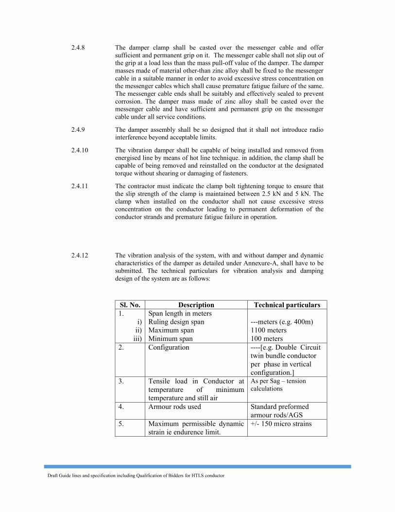
Draft Guide lines and specification including Qualification of Bidders for HTLS conductor
2.4.8 The damper clamp shall be casted over the messenger cable and offer sufficient and permanent grip on it. The messenger cable shall not slip out of the grip at a load less than the mass pull-off value of the damper. The damper masses made of material other-than zinc alloy shall be fixed to the messenger cable in a suitable manner in order to avoid excessive stress concentration on the messenger cables which shall cause premature fatigue failure of the same. The messenger cable ends shall be suitably and effectively sealed to prevent corrosion. The damper mass made of zinc alloy shall be casted over the messenger cable and have sufficient and permanent grip on the messenger cable under all service conditions.
2.4.9 The damper assembly shall be so designed that it shall not introduce radio interference beyond acceptable limits.
2.4.10 The vibration damper shall be capable of being installed and removed from energised line by means of hot line technique. in addition, the clamp shall be capable of being removed and reinstalled on the conductor at the designated torque without shearing or damaging of fasteners.
2.4.11 The contractor must indicate the clamp bolt tightening torque to ensure that the slip strength of the clamp is maintained between 2.5 kN and 5 kN. The clamp when installed on the conductor shall not cause excessive stress concentration on the conductor leading to permanent deformation of the conductor strands and premature fatigue failure in operation.
2.4.12 The vibration analysis of the system, with and without damper and dynamic
characteristics of the damper as detailed under Annexure-A, shall have to be submitted. The technical particulars for vibration analysis and damping design of the system are as follows:
Sl. No. Description Technical particulars 1. Span length in meters
i) Ruling design span ---meters (e.g. 400m) ii) Maximum span 1100 meters
iii) Minimum span 100 meters 2. Configuration ----[e.g. Double Circuit
twin bundle conductor per phase in vertical configuration.]
3. Tensile load in Conductor at temperature of minimum temperature and still air
As per Sag – tension calculations
4. Armour rods used Standard preformed armour rods/AGS
5. Maximum permissible dynamic strain ie endurence limit.
+/- 150 micro strains
Draft Guide lines and specification including Qualification of Bidders for HTLS conductor
2.4.14 The damper placement chart shall be submitted for spans ranging from 100m to 1100m. Placement charts should be duly supported with relevant technical documents and sample calculations.
2.4.15 The damper placement charts shall include the following (1) Location of the dampers for various combinations of spans and line
tensions clearly indicating the number of dampers to be installed per conductor per span.
(2) Placement distances clearly identifying the extremities between which the distances are to be measured.
(3) Placement recommendation depending upon type of suspension clamps (viz Free centre type/Armour grip type etc.)
(4) The influence of mid span compression joints, repair sleeves and armour rods (standard and AGS) in the placement of dampers.
2.5 Bundle Spacer 2.5.1 Armour grip bundle spacers shall be used to maintain the spacing of 450 mm
between the sub-conductors [for 400kV] of each bundle under all normal working conditions.
2.5.2 Spacers offering equivalent or better performance shall also be accepted provided offer meets the qualifying requirements stipulated in the Specification.
2.5.3 The offer shall include placement charts recommending the number of spacers per phase per span and the sub span lengths to be maintained between the spacers while installing on the bundle conductors.
2.5.3.1 The placement of spacers shall be in such a way that adjacent sub spans are sufficiently detuned and the critical wind velocity of each sub span shall be kept more than 30 km/hr and to avoid clashing of sub conductors. The placement shall ensure bundle stability under all operating conditions.
2.5.3.2 The placement chart shall be provided for spans ranging from 100 m to 1100m. The number of spacers recommended for a ruling design span of 400m [for 400kV] shall however be seven with no sub-span greater than 70m and no end sub-span longer than 40m.
2.5.3.3 The Bidder may offer more number of spacers per ruling design span than the specified. However, in such case, suitable price compesation shall be considered for evaluation. For the prupose of price compensation, all the spans shall be assumed to be ruling design spans.
2.5.3.4 The Bidder shall also furnish all the relevant technical documents in support of their placement charts along with the bid.
2.5.4 Jumpers at tension points shall also be fitted with spacers so as to limit the length of free conductor to 3.65 m and to maintain the sub conductor spacing of 450 mm [for 400kV] for bundle conductors. Bidder shall quote for rigid spacer for jumper. It shall meet all the requirements of spacer used in line except for its vibration performance. Spacers requiring retaining rods shall not be quoted for jumpers.
Draft Guide lines and specification including Qualification of Bidders for HTLS conductor
2.5.5 The spacer offered by the Bidder shall satisfy the following requirements. 2.5.5.1 Spacer shall restore normal spacing of the sub-conductors after displacement
by wind, electromagnetic and the electrostatic forces under all operating conditions including the specified short circuit level without permanent deformation damage either to conductor or to the assembly itself. They shall have uniform grip on the conductor
2.5.5.2 For spacer requiring retaining rods, the retaining rods shall be designed for the specified conductor size. The preformed rods shall be made of high strength, special aluminium alloy of type 6061/65032 and shall have minimum tensile strength of 35 kg/sq.mm. The ends of retaining rods should be ball ended. The rods shall be heat-treated to achieve specified mechanical properties and give proper resilience and retain the same during service.
2.5.5.3 Four number of rods shall be applied on each clamps to hold the clamp in position. The minimum diameter of the rods shall be 7.87 + 0.1 mm and the length of the rods shall not be less than 1100 mm.
2.5.5.4 Where elastomer surfaced clamp grooves are used, the elastomer shall be firmly fixed to the clamp. The insert should be forged from aluminium alloy of type 6061/65032. The insert shall be duly heat treated and aged to retain its consistent characteristics during service.
2.5.5.5 Any nut used shall be locked in an approved manner to prevent vibration loosening. The ends of bolts and nuts shall be properly rounded for specified corona performance or suitably shielded.
2.5.5.6 Clamp with cap shall be designed to prevent its cap from slipping out of position when being tightened.
2.5.5.7 The clamp grooves shall be in uniform contact with the conductor over the entire surface, except for rounded edges. The groove of the clamp body and clamp cap shall be smooth and free of projections, grit or other material which cause damage to the conductor when the clamp is installed.
2.5.5.8 For the spacer involving bolted clamps, the manufacturer must indicate the clamp bolt tightening torque to ensure that the slip strength of the clamp is maintained between 2.5 kN and 5 kN. The clamp when installed on the conductor shall not cause excessive stress concentration on the conductor leading to permanent deformation of the conductor strands and premature fatigue failure in operation.
2.5.5.9 Universal type bolted clamps, covering a range of conductor sizes, will not be permitted.
2.5.5.10 No rubbing, other than that of the conductor clamp hinges or clamp swing bolts, shall take place between any parts of the spacer. Joint incorporating a flexible medium shall be such that there is no relative slip between them.
2.5.5.11 The spacer shall be suitably designed to avoid distortion or damage to the conductor or to themselves during service.
2.5.5.12 Rigid spacers shall be acceptable only for jumpers. 2.5.5.13 The spacer shall not damage or chafe the conductor in any way which might
affect its mechanical and fatigue strength or corona performance. 2.5.5.14 The clamping system shall be designed to compensate for any reduction in
diameter of conductor due to creep.
Draft Guide lines and specification including Qualification of Bidders for HTLS conductor
2.5.5.15 The spacer assembly shall not have any projections, cuts, abrasions etc. or chattering parts which might cause corona or RIV.
2.5.5.16 The spacer tube shall be made of aluminium alloy of type 6061/65032. If fasteners of ferrous material are used, they shall conform to and be galvanised conforming to relevant Indian Standards.
2.5.5.17 Elastomer, if used, shall be resistant to the effects of temperature upto the designed maximum temperature specified for the conductor, ultraviolet radiation and other atmospheric contaminants likely to be encountered in service. It shall have good fatigue characteristics. The physical properties of the elastomer shall be of approved standard. The supplier shall submit relevant type/ performance test certificate as per applicable standard/ product specification for elastomer to confirm suitability of the offered elastomer for the specified application.
2.5.5.18 The spacer assembly shall have electrical continuity. The electrical resistance between the sub-conductor across the assembly in case of spacer having elastomer clamp grooves shall be suitably selected by the manufacturers to ensure satisfactory electrical performance and to avoid deterioration of elastomer under all service conditions.
2.5.5.19 The spacer assembly shall have complete ease of installation and shall be capable of removal/reinstallation without any damage.
2.5.5.20 The spacer assembly shall be capable of being installed and removed from the energised line by means of hot line technique.
2.6 Spacer Damper (Alternative to Vibration Damper & Bundle Spacer) 2.6.1 Suitable spacer dampers for HTLS conductor can be offered as an alternative
to the combination of Vibration Damper and Bundle Spacer. The spacer damper covered by this specification shall be designed to maintain the bundle spacing of 450 mm under all normal operating conditions and to effectively control Aeolian vibrations as well as sub span oscillation and to restore conductor spacing after release of any external extraordinary load. The nominal sub conductor spacing shall be maintained within ±5 mm.
2.6.2 The spacer damper shall restore the normal sub-conductor spacing due to displacement by wind, electromagnetic and electrostatic forces including the specified short circuit level without permanent deformation or damage either to bundle conductors or to spacer damper itself.
2.6.3 The design offered shall be presented as a system consisting of spacer
dampers and their staggering scheme for spans ranging from 100 m to 1100 m.
2.6.4 Under the operating conditions specified, the spacer damper system shall
adequately control Aeolian vibrations throughout the life of the transmission line with wind velocity ranging from 0 to 30 km per hour in order to prevent damage to conductor at suspension clamps, dead end clamps and spacer damper clamps.
2.6.5 The spacer damper system shall also control the sub-span oscillations in order
to prevent conductor damage due to chaffing and severe bending stresses at the spacer damper clamps as well as suspension and dead end clamps and to avoid wear to spacer damper components.
Draft Guide lines and specification including Qualification of Bidders for HTLS conductor
2.6.6 The spacer damper shall consist of a rigid central body called the frame linked to the conductor by two articulated arms terminated by suitable clamping system. The articulation shall be designed to provide elastic and damping forces under angular movement of the arms. The dynamic characteristics of the articulations shall be maintained for the whole life of the transmission line.
2.6.7 The clamping system shall be designed to provide firm but gentle and
permanent grip while protecting the conductor against local static or dynamic stresses expected during normal operating conditions. The clamping system shall be designed to compensate for any reduction of conductor diameter due to creep.
2.6.8 Bolted type clamps shall allow installation without removal of the bolts or the
clamps from clamp body. Locking mechanism shall be suitable to prevent bolt loosening. Clamp locking devices with small loose components shall not be accepted. Nut cracker, hinged open or boltless type clamps are acceptable provided adequate grip can be maintained on the conductor.
2.6.9 Bolts and nuts shall be of mild steel, stainless steel, or high strength steel in
accordance with the design of the spacer damper.
2.6.10 Where elastomer surfaced clamps are used, the elastomer elements shall be firmly fixed to the clamp. The insert should be forged from aluminium alloy of type 6061 or equivalent aluminium alloy having minimum tensile strength of 25 kg/mm2. The insert shall be moulded on the insert surface. The insert shall be duly heat treated and aged to retain its consistent characteristics during service. The grain flow of the forged insert shall be in the direction of the maximum tension and compression loads experienced.
2.6.11 If clamps involving preformed rods are used, these rods shall be designed for
specific conductor size. They shall be made of high strength aluminium alloy of type 6061 or equivalent aluminium alloy having a minimum tensile strength of 35 kg/mm3. The rods shall be ball ended. The rods shall be heat treated and aged to achieve specified mechanical properties and to retain the same during service. The length of the rods shall be such that the ends fall inside the imaginary square whose sides are vertical and horizontal outer tangents to the conductor sections.
2.6.12 The spacer damper body shall be cast/ forged from suitable high strength
corrosion resistant aluminum alloy. The aluminium alloy shall be chosen in relation with the process used.
2.6.13 The rubber components involved in the design such as damping elements
shall be made with rubber compound selected specifically for that particular application. The Contractor shall submit a complete list of physical and mechanical properties of the elastomer used. This list shall make reference to all applicable ASTM standards.
2.6.14 The rubber components used shall have good resistance to the effects of
temperature up to the designed maximum temperature of the conductor and to ultraviolet radiation, ozone and other atmospheric contaminants. The rubber shall have good wear and fatigue resistance and shall be electrically semi-conductive.
Draft Guide lines and specification including Qualification of Bidders for HTLS conductor
2.6.15 The spacer damper involving ferrous material shall not have magnetic power
loss more than 1 watt. 2.6.16 The spacer damper assembly shall have electrical continuity. The electrical
resistance between the sub-conductors across the assembly in case of spacer damper involving elastomer surfaced clamps shall be suitably selected by the manufacturer to ensure satisfactory electrical performance and avoid deterioration of elastomer under service conditions.
2.6.17 The spacer damper assembly shall have complete ease of installation and
shall be capable of removal/reinstallation without any damage. 2.6.18 The spacer damper assembly shall be capable of being installed and removed
from the energized line by means of hot line techniques. The Bidder shall supply with the bid the complete description of the installation, removal and reinstallation procedure.
2.6.19 The Bidder shall recommend the staggering scheme for installation of spacer
dampers on the line which shall ensure most satisfactory fatigue performance of the line as specified. The scheme shall indicate the number of spacer dampers per phase per span and the sub span lengths to be maintained between spacer dampers while installing on the bundle conductors.
2.6.20 The staggering scheme shall be provided for spans ranging from 100 m to
1100 m. The number of spacer dampers for a nominal ruling span of 400 m [for 400kV] shall not be less than six.
2.6.21 No sub span shall be greater than 70 m and no end sub span shall be longer
than 40 m. 2.6.22 The staggering scheme shall be such that the spacer dampers be unequally
distributed along the span to achieve sufficient detuning of adjacent subs pans for oscillations of sub span mode and to ensure bundle stability for wind speeds up to 60 km/hr.
2.6.23 The manufacturer / supplier shall supply free of cost 25 number fixed setting
torque wrench ( of torque as per spacer damper design) along with 1st batch of supply of spacer dampers for installation of spacer damper on the line by the tower contractors.
2.6.24 The Bidder shall furnish all the relevant technical documents in supports of
the staggering scheme recommended for the spacer damper. 2.7 Material and Workmanship 2.7.1 All the equipment shall be of the latest proven design and conform to the best
modern practice adopted in the extra high voltage field. The Bidder shall offer only such equipment as guaranteed by him to be satisfactory and suitable for --- kV transmission line application with / without bundle conductors and will give continued good performance at all service conditions. For employer’s review of the offered design of accessories, the supplier shall submit document/design details of similar type of accessories used in past for similar type of HTLS conductor application

Draft Guide lines and specification including Qualification of Bidders for HTLS conductor
2.7.2 The design, manufacturing process and quality control of all the materials shall be such as to achieve requisite factor of safety for maximum working load, highest mobility, elimination of sharp edges and corners, best resistance to corrosion and a good finish.
2.7.3 High current, heat rise test shall be conducted by the supplier to determine the maximum temperature achieved in different components of fittings/ accessories under simulated service condition corresponding to continuous operation of conductor at designed maximum temperature. The material of the components should be suitable for continued good performance corresponding to these maximum temperatures. The supplier shall submit relevant type/ performance test certificates as per applicable standards/product specifications to confirm suitability of the offered material.
2.7.4 All ferrous parts shall be hot dip galvanised, after all machining has been completed. Nuts may, however, be tapped (threaded) after galvanising and the threads oiled. Spring washers shall be electro galvanised as per grade 4 of IS-1573. The bolt threads shall be undercut to take care of increase in diameter due to galvanising. Galvanising shall be’done in accordance with IS:2629/ IS-1367 (Part-13) and satisfy the tests mentioned in IS-2633. Fasteners shall withstand four dips while spring washers shall withstand three dips. Other galvanised materials shall have a minimum average coating of Zinc equivalent to 600 gm/sq.m and shall be guaranteed to withstand at least six dips each lasting one minute under the standard Preece test for galvanising unless otherwise specified.
2.7.5 The zinc coating shall be perfectly adherent, of uniform thickness, smooth, reasonably bright, continuous and free from imperfections such as flux, ash, rust stains, bulky white deposits and blisters. The zinc used for galvanising shall be of grade Zn 99.95 as per IS:209.
2.7.6 In case of castings, the same shall be free from all internal defects like shrinkage, inclusion, blow holes, cracks etc.
2.7.7 All current carrying parts shall be so designed and manufactured that contact resistance is reduced to minimum and localised heating phenomenon is averted.
2.7.8 No equipment shall have sharp ends or edges, abrasions or projections and shall not cause any damage to the conductor in any way during erection or during continuous operation which would produce high electrical and mechanical stresses in normal working. The design of adjacent metal parts and mating surfaces shall be such as to prevent corrosion of the contact surface and to maintain good electrical contact under all service conditions.
2.7.9 Particular care shall be taken during manufacture and subsequent handling to ensure smooth surface free from abrasion or cuts.
2.7.10 The fasteners shall conform to the requirements of IS:6639-1972. All fasteners and clamps shall have corona free locking arrangement to guard against vibration loosening.
2.8 Compression Markings Die compression areas shall be clearly marked on each equipment designed
for continuous die compressions and shall bear the words ‘COMPRESS FIRST’ ‘suitably inscribed on each equipment where the compression begins. If the equipment is designed for intermittent die compressions, it shall bear the identification marks ‘COMPRESSION ZONE’ and ‘NON-

Draft Guide lines and specification including Qualification of Bidders for HTLS conductor
COMPRESSION ZONE’ distinctly with arrow marks showing the direction of compression and knurling marks showing the end of the zones. The letters, number and other markings on finished equipment shall be distinct and legible.
3.0 Tests and Standards 3.1 Type Tests 3.1.1 On Suspension Clamp a) Magnetic power loss test : As per Annexure-A b) Clamp slip strength Vs torque test : As per Annexure-A c) Ozone Test on elastomer : As per Annexure-A d) Vertical damage load & Failure load test : IEC:61284 3.1.2 On Dead end Tension Assembly a) Electrical resistance test for dead end Assembly : As per IS:2486-(Part-I) b) Heating cycle test for dead end Assembly : As per Annexure-A c) Slip strength test for dead end assembly : As per Annexure-A d) Ageing test on filler (if applicable) : As per Annexure-A 3.1.3 Mid Span Compression Joint for Conductor a) Chemical analysis of materials : As per Annexure-A b) Electrical resistance test :As per IS:2121 (Part-II) c) Heating cycle test :As per Annexure-A d) Slip strength test : As per Annexure-A e) Corona extinction voltage test (dry)[for 400kV] : As per Annexure-A f) Radio interference voltage test (dry) [for 400kV] : As per Annexure-A 3.1.4 Repair Sleeve for Conductor a) Chemical analysis of materials : As per Annexure-A b) Corona extinction voltage test (dry) [for 400kV] : As per Annexure-A c) Radio interference voltage test (dry) [for 400kV] : As per Annexure-A 3.1.5 Vibration Damper for Conductor a) Chemical analysis of materials : As per Annexure-A b) Dynamic characteristics test* : As per Annexure-A c) Vibration analysis : As per Annexure-A d) Clamp slip test : As per Annexure-A
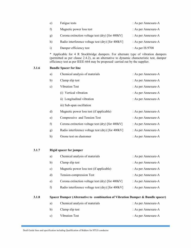
Draft Guide lines and specification including Qualification of Bidders for HTLS conductor
e) Fatigue tests : As per Annexure-A f) Magnetic power loss test : As per Annexure-A g) Corona extinction voltage test (dry) [for 400kV] : As per Annexure-A h) Radio interference voltage test (dry) [for 400kV] : As per Annexure-A i) Damper efficiency test : As per IS:9708 * Applicable for 4 R Stockbridge dampers. For alternate type of vibration dampers
(permitted as per clause 2.4.2), as an alternative to dynamic characteristic test, damper efficiency test as per IEEE-664 may be proposed/ carried out by the supplier.
3.1.6 Bundle Spacer for line a) Chemical analysis of materials : As per Annexure-A b) Clamp slip test : As per Annexure-A c) Vibration Test : As per Annexure-A (i) Vertical vibration : As per Annexure-A ii) Longitudinal vibration : As per Annexure-A iii) Sub-span oscillation d) Magnetic power loss test (if applicable) : As per Annexure-A e) Compressive and Tension Test : As per Annexure-A f) Corona extinction voltage test (dry) [for 400kV] : As per Annexure-A g) Radio interference voltage test (dry) [for 400kV] : As per Annexure-A h) Ozone test on elastomer : As per Annexure-A
3.1.7 Rigid spacer for jumper a) Chemical analysis of materials : As per Annexure-A b) Clamp slip test : As per Annexure-A c) Magnetic power loss test (if applicable) : As per Annexure-A d) Tension-compression Test : As per Annexure-A e) Corona extinction voltage test (dry) [for 400kV] : As per Annexure-A f) Radio interference voltage test (dry) [for 400kV] : As per Annexure-A
3.1.8 Spacer Damper (Alternative to combination of Vibration Damper & Bundle spacer) a) Chemical analysis of materials : As per Annexure-A b) Clamp slip test : As per Annexure-A c) Vibration Test : As per Annexure-A
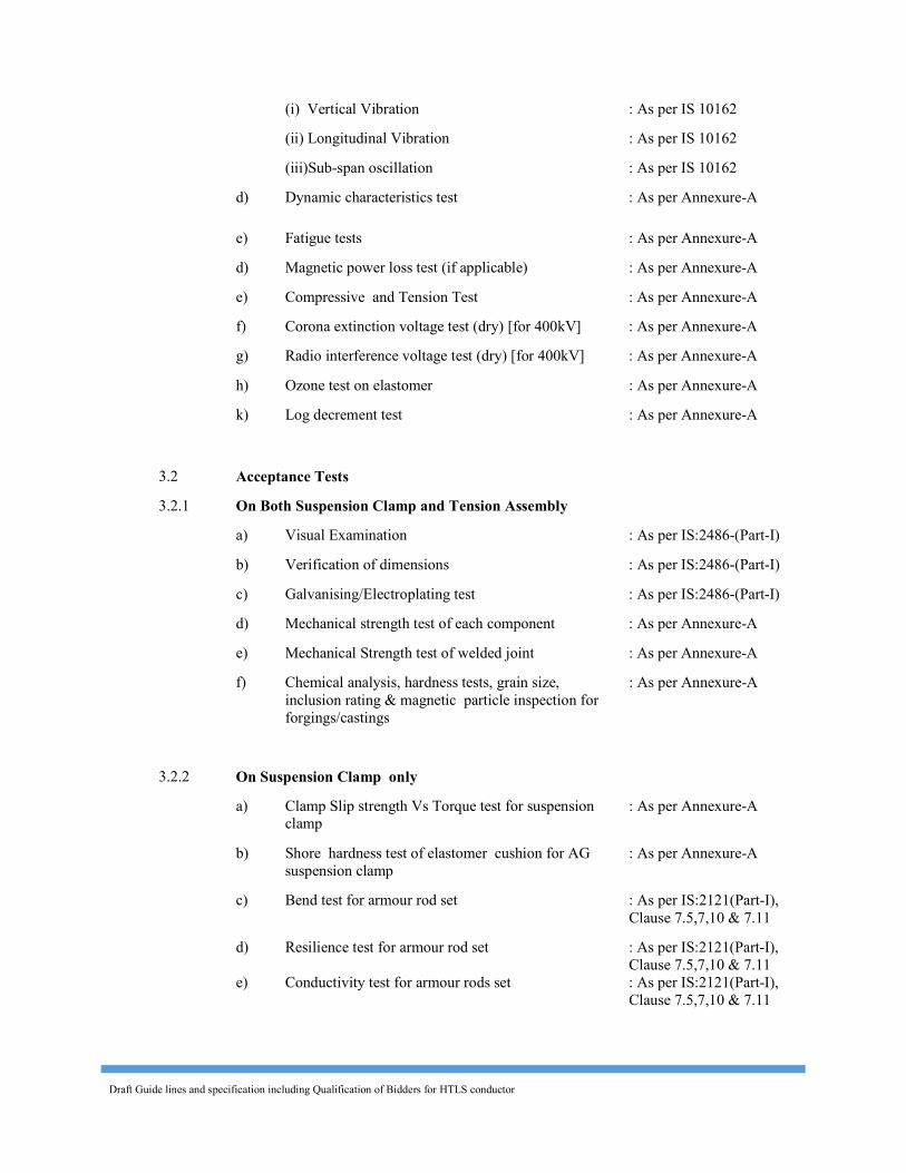
Draft Guide lines and specification including Qualification of Bidders for HTLS conductor
(i) Vertical Vibration : As per IS 10162 (ii) Longitudinal Vibration : As per IS 10162 (iii)Sub-span oscillation : As per IS 10162 d) Dynamic characteristics test : As per Annexure-A e) Fatigue tests : As per Annexure-A d) Magnetic power loss test (if applicable) : As per Annexure-A e) Compressive and Tension Test : As per Annexure-A f) Corona extinction voltage test (dry) [for 400kV] : As per Annexure-A g) Radio interference voltage test (dry) [for 400kV] : As per Annexure-A h) Ozone test on elastomer : As per Annexure-A k) Log decrement test : As per Annexure-A
3.2 Acceptance Tests 3.2.1 On Both Suspension Clamp and Tension Assembly a) Visual Examination : As per IS:2486-(Part-I) b) Verification of dimensions : As per IS:2486-(Part-I) c) Galvanising/Electroplating test : As per IS:2486-(Part-I) d) Mechanical strength test of each component : As per Annexure-A e) Mechanical Strength test of welded joint : As per Annexure-A f) Chemical analysis, hardness tests, grain size,
inclusion rating & magnetic particle inspection for forgings/castings
: As per Annexure-A
3.2.2 On Suspension Clamp only a) Clamp Slip strength Vs Torque test for suspension
clamp : As per Annexure-A
b) Shore hardness test of elastomer cushion for AG suspension clamp
: As per Annexure-A
c) Bend test for armour rod set : As per IS:2121(Part-I), Clause 7.5,7,10 & 7.11
d) Resilience test for armour rod set : As per IS:2121(Part-I), Clause 7.5,7,10 & 7.11
e) Conductivity test for armour rods set : As per IS:2121(Part-I), Clause 7.5,7,10 & 7.11
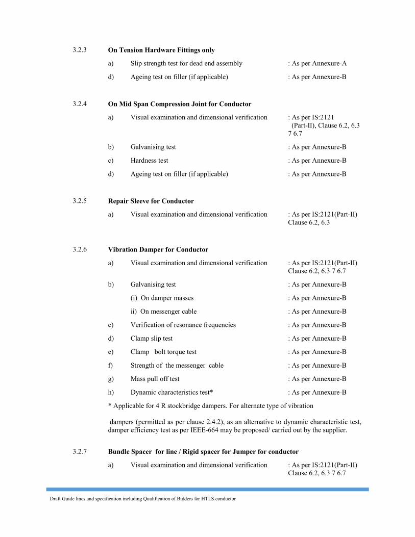
Draft Guide lines and specification including Qualification of Bidders for HTLS conductor
3.2.3 On Tension Hardware Fittings only a) Slip strength test for dead end assembly : As per Annexure-A d) Ageing test on filler (if applicable) : As per Annexure-B 3.2.4 On Mid Span Compression Joint for Conductor a) Visual examination and dimensional verification : As per IS:2121
(Part-II), Clause 6.2, 6.3 7 6.7
b) Galvanising test : As per Annexure-B c) Hardness test : As per Annexure-B d) Ageing test on filler (if applicable) : As per Annexure-B
3.2.5 Repair Sleeve for Conductor a) Visual examination and dimensional verification : As per IS:2121(Part-II)
Clause 6.2, 6.3 3.2.6 Vibration Damper for Conductor a) Visual examination and dimensional verification : As per IS:2121(Part-II)
Clause 6.2, 6.3 7 6.7 b) Galvanising test : As per Annexure-B (i) On damper masses : As per Annexure-B ii) On messenger cable : As per Annexure-B c) Verification of resonance frequencies : As per Annexure-B d) Clamp slip test : As per Annexure-B e) Clamp bolt torque test : As per Annexure-B f) Strength of the messenger cable : As per Annexure-B g) Mass pull off test : As per Annexure-B h) Dynamic characteristics test* : As per Annexure-B * Applicable for 4 R stockbridge dampers. For alternate type of vibration
dampers (permitted as per clause 2.4.2), as an alternative to dynamic characteristic test, damper efficiency test as per IEEE-664 may be proposed/ carried out by the supplier.
3.2.7 Bundle Spacer for line / Rigid spacer for Jumper for conductor a) Visual examination and dimensional verification : As per IS:2121(Part-II)
Clause 6.2, 6.3 7 6.7
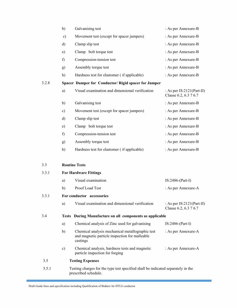
Draft Guide lines and specification including Qualification of Bidders for HTLS conductor
b) Galvanising test : As per Annexure-B c) Movement test (except for spacer jumpers) : As per Annexure-B d) Clamp slip test : As per Annexure-B e) Clamp bolt torque test : As per Annexure-B f) Compression-tension test : As per Annexure-B g) Assembly torque test : As per Annexure-B h) Hardness test for elastomer ( if applicable) : As per Annexure-B 3.2.8 Spacer Damper for Conductor/ Rigid spacer for Jumper a) Visual examination and dimensional verification : As per IS:2121(Part-II)
Clause 6.2, 6.3 7 6.7 b) Galvanising test : As per Annexure-B c) Movement test (except for spacer jumpers) : As per Annexure-B d) Clamp slip test : As per Annexure-B e) Clamp bolt torque test : As per Annexure-B f) Compression-tension test : As per Annexure-B g) Assembly torque test : As per Annexure-B h) Hardness test for elastomer ( if applicable) : As per Annexure-B 3.3 Routine Tests 3.3.1 For Hardware Fittings a) Visual examination IS:2486-(Part-I) b) Proof Load Test : As per Annexure-A 3.3.1 For conductor accessories a) Visual examination and dimensional verification : As per IS:2121(Part-II)
Clause 6.2, 6.3 7 6.7 3.4 Tests During Manufacture on all components as applicable a) Chemical analysis of Zinc used for galvanising IS:2486-(Part-I) b) Chemical analysis mechanical metallographic test
and magnetic particle inspection for malleable castings
: As per Annexure-A
c) Chemical analysis, hardness tests and magnetic particle inspection for forging
: As per Annexure-A
3.5 Testing Expenses 3.5.1 Testing charges for the type test specified shall be indicated separately in the
prescribed schedule.
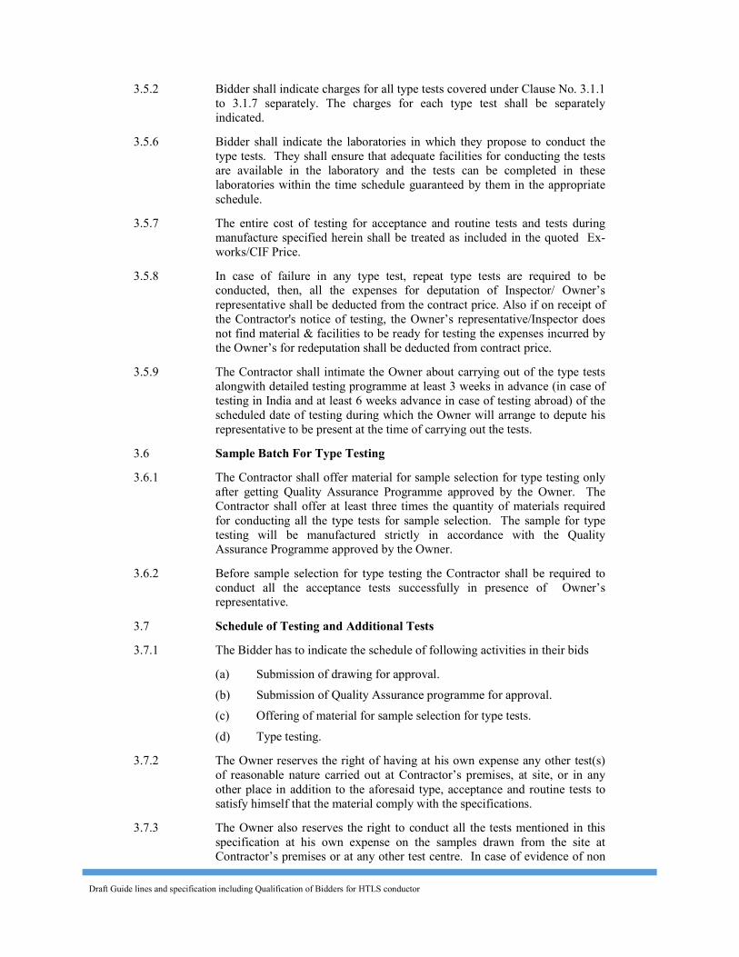
Draft Guide lines and specification including Qualification of Bidders for HTLS conductor
3.5.2 Bidder shall indicate charges for all type tests covered under Clause No. 3.1.1 to 3.1.7 separately. The charges for each type test shall be separately indicated.
3.5.6 Bidder shall indicate the laboratories in which they propose to conduct the type tests. They shall ensure that adequate facilities for conducting the tests are available in the laboratory and the tests can be completed in these laboratories within the time schedule guaranteed by them in the appropriate schedule.
3.5.7 The entire cost of testing for acceptance and routine tests and tests during manufacture specified herein shall be treated as included in the quoted Ex-works/CIF Price.
3.5.8 In case of failure in any type test, repeat type tests are required to be conducted, then, all the expenses for deputation of Inspector/ Owner’s representative shall be deducted from the contract price. Also if on receipt of the Contractor's notice of testing, the Owner’s representative/Inspector does not find material & facilities to be ready for testing the expenses incurred by the Owner’s for redeputation shall be deducted from contract price.
3.5.9 The Contractor shall intimate the Owner about carrying out of the type tests alongwith detailed testing programme at least 3 weeks in advance (in case of testing in India and at least 6 weeks advance in case of testing abroad) of the scheduled date of testing during which the Owner will arrange to depute his representative to be present at the time of carrying out the tests.
3.6 Sample Batch For Type Testing 3.6.1 The Contractor shall offer material for sample selection for type testing only
after getting Quality Assurance Programme approved by the Owner. The Contractor shall offer at least three times the quantity of materials required for conducting all the type tests for sample selection. The sample for type testing will be manufactured strictly in accordance with the Quality Assurance Programme approved by the Owner.
3.6.2 Before sample selection for type testing the Contractor shall be required to conduct all the acceptance tests successfully in presence of Owner’s representative.
3.7 Schedule of Testing and Additional Tests 3.7.1 The Bidder has to indicate the schedule of following activities in their bids (a) Submission of drawing for approval. (b) Submission of Quality Assurance programme for approval. (c) Offering of material for sample selection for type tests. (d) Type testing. 3.7.2 The Owner reserves the right of having at his own expense any other test(s)
of reasonable nature carried out at Contractor’s premises, at site, or in any other place in addition to the aforesaid type, acceptance and routine tests to satisfy himself that the material comply with the specifications.
3.7.3 The Owner also reserves the right to conduct all the tests mentioned in this specification at his own expense on the samples drawn from the site at Contractor’s premises or at any other test centre. In case of evidence of non
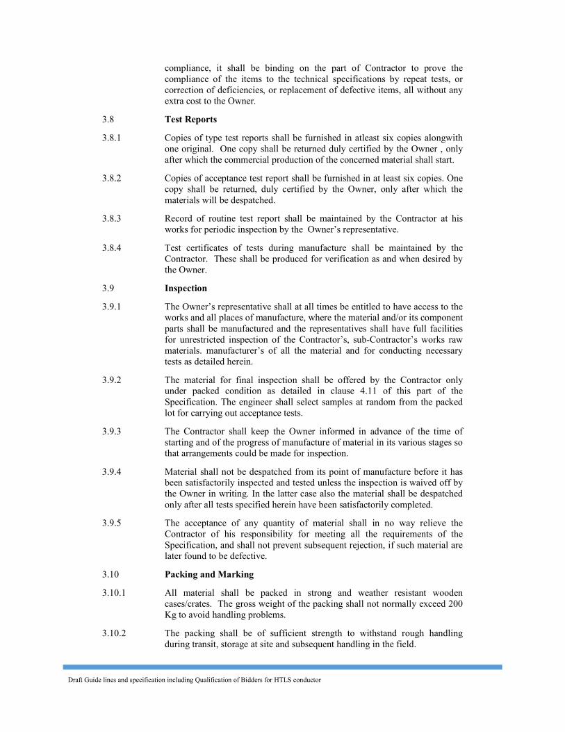
Draft Guide lines and specification including Qualification of Bidders for HTLS conductor
compliance, it shall be binding on the part of Contractor to prove the compliance of the items to the technical specifications by repeat tests, or correction of deficiencies, or replacement of defective items, all without any extra cost to the Owner.
3.8 Test Reports 3.8.1 Copies of type test reports shall be furnished in atleast six copies alongwith
one original. One copy shall be returned duly certified by the Owner , only after which the commercial production of the concerned material shall start.
3.8.2 Copies of acceptance test report shall be furnished in at least six copies. One copy shall be returned, duly certified by the Owner, only after which the materials will be despatched.
3.8.3 Record of routine test report shall be maintained by the Contractor at his works for periodic inspection by the Owner’s representative.
3.8.4 Test certificates of tests during manufacture shall be maintained by the Contractor. These shall be produced for verification as and when desired by the Owner.
3.9 Inspection 3.9.1 The Owner’s representative shall at all times be entitled to have access to the
works and all places of manufacture, where the material and/or its component parts shall be manufactured and the representatives shall have full facilities for unrestricted inspection of the Contractor’s, sub-Contractor’s works raw materials. manufacturer’s of all the material and for conducting necessary tests as detailed herein.
3.9.2 The material for final inspection shall be offered by the Contractor only under packed condition as detailed in clause 4.11 of this part of the Specification. The engineer shall select samples at random from the packed lot for carrying out acceptance tests.
3.9.3 The Contractor shall keep the Owner informed in advance of the time of starting and of the progress of manufacture of material in its various stages so that arrangements could be made for inspection.
3.9.4 Material shall not be despatched from its point of manufacture before it has been satisfactorily inspected and tested unless the inspection is waived off by the Owner in writing. In the latter case also the material shall be despatched only after all tests specified herein have been satisfactorily completed.
3.9.5 The acceptance of any quantity of material shall in no way relieve the Contractor of his responsibility for meeting all the requirements of the Specification, and shall not prevent subsequent rejection, if such material are later found to be defective.
3.10 Packing and Marking 3.10.1 All material shall be packed in strong and weather resistant wooden
cases/crates. The gross weight of the packing shall not normally exceed 200 Kg to avoid handling problems.
3.10.2 The packing shall be of sufficient strength to withstand rough handling during transit, storage at site and subsequent handling in the field.
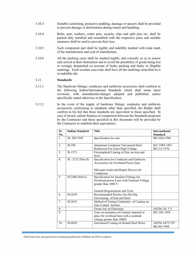
Draft Guide lines and specification including Qualification of Bidders for HTLS conductor
3.10.3 Suitable cushioning, protective padding, dunnage or spacers shall be provided to prevent damage or deformation during transit and handling.
3.10.4 Bolts, nuts, washers, cotter pins, security clips and split pins etc. shall be packed duly installed and assembled with the respective parts and suitable measures shall be used to prevent their loss.
3.10.5 Each component part shall be legibly and indelibly marked with trade mark of the manufacturer and year of manufacture.
3.10.6 All the packing cases shall be marked legibly and correctly so as to ensure safe arrival at their destination and to avoid the possibility of goods being lost or wrongly despatched on account of faulty packing and faulty or illegible markings. Each wooden case/crate shall have all the markings stencilled on it in indelible ink.
3.11 Standards 3.11.1 The Hardware fittings; conductor and earthwire accessories shall conform to
the following Indian/International Standards which shall mean latest revisions, with amendments/changes adopted and published, unless specifically stated otherwise in the Specification.
3.11.2 In the event of the supply of hardware fittings; conductor and earthwire accessories conforming to standards other than specified, the Bidder shall confirm in his bid that these standards are equivalent to those specified. In case of award, salient features of comparison between the Standards proposed by the Contractor and those specified in this document will be provided by the Contractor to establish their equivalence.
Sl. No.
Indian Standard Title International Standard
1. IS: 209-1992 Specification for zinc BS:3436-1986
2. IS:398 Aluminum Conductor Galvanised Steel- Reinforced For Extra High Voltage
IEC:1089-1991 BS:215-1970
3. IS 1573 Electroplated Coating of Zinc on iron and Steel
4. IS : 2121 (Part-II) Specification for Conductor and Earthwire
Accessories for Overhead Power lines: Mid-span Joints and Repair Sleeves for Conductors
5. IS:2486 (Part-I) Specification for Insulator Fittings for Overhead power Lines with Nominal Voltage greater than 1000 V: General Requirements and Tests
6. IS:2629 Recommended Practice for Hot Dip Galvanising of Iron and Steel
7. IS:2633 Method of Testing Uniformity of Coating on
Zinc Coated Articles
8. Ozone test on Elastomer ASTM- D1 171 9. Tests on insulators of Ceramic material or
glass for overhead lines with a nominal voltage greater than 1000V
IEC:383-1993
10. IS:4826 Galvanised Coating on Round Steel Wires ASTM A472-729 BS:443-1969
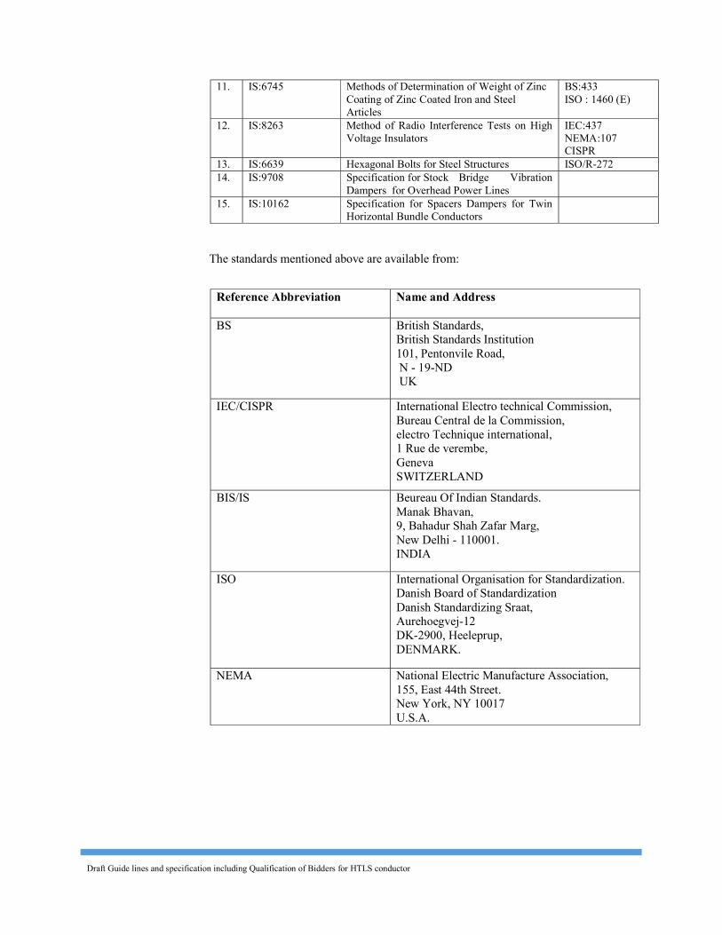
Draft Guide lines and specification including Qualification of Bidders for HTLS conductor
11. IS:6745 Methods of Determination of Weight of Zinc Coating of Zinc Coated Iron and Steel Articles
BS:433 ISO : 1460 (E)
12. IS:8263 Method of Radio Interference Tests on High Voltage Insulators
IEC:437 NEMA:107 CISPR
13. IS:6639 Hexagonal Bolts for Steel Structures ISO/R-272 14. IS:9708 Specification for Stock Bridge Vibration
Dampers for Overhead Power Lines
15. IS:10162 Specification for Spacers Dampers for Twin Horizontal Bundle Conductors
The standards mentioned above are available from:
Reference Abbreviation
Name and Address BS British Standards,
British Standards Institution 101, Pentonvile Road, N - 19-ND UK
IEC/CISPR International Electro technical Commission, Bureau Central de la Commission, electro Technique international, 1 Rue de verembe, Geneva SWITZERLAND
BIS/IS Beureau Of Indian Standards. Manak Bhavan, 9, Bahadur Shah Zafar Marg, New Delhi - 110001. INDIA
ISO International Organisation for Standardization. Danish Board of Standardization Danish Standardizing Sraat, Aurehoegvej-12 DK-2900, Heeleprup, DENMARK.
NEMA National Electric Manufacture Association, 155, East 44th Street. New York, NY 10017 U.S.A.
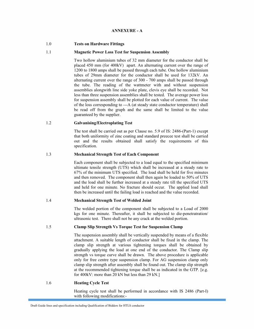
Draft Guide lines and specification including Qualification of Bidders for HTLS conductor
ANNEXURE - A 1.0 Tests on Hardware Fittings 1.1 Magnetic Power Loss Test for Suspension Assembly Two hollow aluminium tubes of 32 mm diameter for the conductor shall be
placed 450 mm (for 400kV) apart. An alternating current over the range of 1200 to 1800 amps shall be passed through each tube. One hollow aluminium tubes of 29mm diameter for the conductor shall be used for 132kV. An alternating current over the range of 300 - 700 amps shall be passed through the tube. The reading of the wattmeter with and without suspension assemblies alongwith line side yoke plate, clevis eye shall be recorded. Not less than three suspension assemblies shall be tested. The average power loss for suspension assembly shall be plotted for each value of current. The value of the loss corresponding to ---A (at steady state conductor temperature) shall be read off from the graph and the same shall be limited to the value guaranteed by the supplier.
1.2 Galvanising/Electroplating Test The test shall be carried out as per Clause no. 5.9 of IS: 2486-(Part-1) except
that both uniformity of zinc coating and standard preecee test shall be carried out and the results obtained shall satisfy the requirements of this specification.
1.3 Mechanical Strength Test of Each Component Each component shall be subjected to a load equal to the specified minimum
ultimate tensile strength (UTS) which shall be increased at a steady rate to 67% of the minimum UTS specified. The load shall be held for five minutes and then removed. The component shall then again be loaded to 50% of UTS and the load shall be further increased at a steady rate till the specified UTS and held for one minute. No fracture should occur. The applied load shall then be increased until the failing load is reached and the value recorded.
1.4 Mechanical Strength Test of Welded Joint The welded portion of the component shall be subjected to a Load of 2000
kgs for one minute. Thereafter, it shall be subjected to die-penetratration/ ultrasonic test. There shall not be any crack at the welded portion.
1.5 Clamp Slip Strength Vs Torque Test for Suspension Clamp The suspension assembly shall be vertically suspended by means of a flexible
attachment. A suitable length of conductor shall be fixed in the clamp. The clamp slip strength at various tightening torques shall be obtained by gradually applying the load at one end of the conductor. The Clamp slip strength vs torque curve shall be drawn. The above procedure is applicable only for free centre type suspension clamp. For AG suspension clamp only clamp slip strength after assembly shall be found out. The clamp slip strength at the recommended tightening torque shall be as indicated in the GTP. [e.g. for 400kV: more than 20 kN but less than 29 kN.]
1.6 Heating Cycle Test Heating cycle test shall be performed in accordance with IS 2486 (Part-I)
with following modifications:-
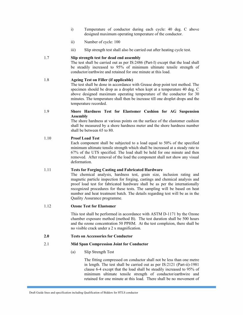
Draft Guide lines and specification including Qualification of Bidders for HTLS conductor
i) Temperature of conductor during each cycle: 40 deg. C above designed maximum operating temperature of the conductor.
ii) Number of cycle: 100 iii) Slip strength test shall also be carried out after heating cycle test.
1.7 Slip strength test for dead end assembly The test shall be carried out as per IS:2486 (Part-I) except that the load shall be steadily increased to 95% of minimum ultimate tensile strength of conductor/earthwire and retained for one minute at this load.
1.8 Ageing Test on Filler (if applicable) The test shall be done in accordance with Grease drop point test method. The specimen should be drop as a droplet when kept at a temperature 40 deg. C above designed maximum operating temperature of the conductor for 30 minutes. The temperature shall then be increase till one droplet drops and the temperature recorded.
1.9 Shore Hardness Test for Elastomer Cushion for AG Suspension Assembly
The shore hardness at various points on the surface of the elastomer cushion shall be measured by a shore hardness meter and the shore hardness number shall be between 65 to 80.
1.10 Proof Load Test Each component shall be subjected to a load equal to 50% of the specified
minimum ultimate tensile strength which shall be increased at a steady rate to 67% of the UTS specified. The load shall be held for one minute and then removed. After removal of the load the component shall not show any visual deformation.
1.11 Tests for Forging Casting and Fabricated Hardware The chemical analysis, hardness test, grain size, inclusion rating and
magnetic particle inspection for forging, castings and chemical analysis and proof load test for fabricated hardware shall be as per the internationally recognized procedures for these tests. The sampling will be based on heat number and heat treatment batch. The details regarding test will be as in the Quality Assurance programme.
1.12 Ozone Test for Elastomer This test shall be performed in accordance with ASTM D-1171 by the Ozone
chamber exposure method (method B). The test duration shall be 500 hours and the ozone concentration 50 PPHM. At the test compleion, there shall be no visible crack under a 2 x magnification.
2.0 Tests on Accessories for Conductor 2.1 Mid Span Compression Joint for Conductor (a) Slip Strength Test The fitting compressed on conductor shall not be less than one metre
in length. The test shall be carried out as per IS:2121 (Part-ii)-1981 clause 6-4 except that the load shall be steadily increased to 95% of minimum ultimate tensile strength of conductor/earthwire and retained for one minute at this load. There shall be no movement of
Draft Guide lines and specification including Qualification of Bidders for HTLS conductor
the conductor/ earthwire relative to the fittings and no failure of the fit tings during this one minute period.
(b) Heating Cycle Test Heating cycle test shall be performed in accordance with IS 2121
(Part-II-1981 ) with following modifications:- i) Temperature of conductor during each cycle: 40 deg. C above
designed maximum operating temperature of the conductor. ii) Number of cycle: 100 iii) Slip strength test shall also be carried out after heating cycle test.
2.2 Vibration Damper for Conductor (a) Dynamic Characteristics, Test The damper shall be mounted with its clamp tightened with torque
recommended by the manufacturer on shaker table capable of simulating sinusoidal vibrations for aeolian vibration frequency band ranging from 0.18/d to 1.4/d where d is the conductor diameter in meters. The damper assembly shall be vibrated verticially with a + 1 mm amplitude from 5 to 15 Hz frequency and beyond 15 Hz at ± 0.5mm to determine following characteristics with the help of suitable recording instruments:
(i) Force Vs frequency (ii) Phase angle Vs frequency (iii) Power dissipation Vs frequency The Force Vs frequency curve shall not show steep peaks at
resonance frequencies and deep troughs between the resonance frequencies. The resonance frequencies shall be suitably spread within the aeolian vibration frequency-band between the lower and upper dangerous frequency, limits determined by the vibration analysis of conductor without dampers.
Acceptance criteria for vibration damper. (i) The above dynamic characteristics test on five damper shall
be conducted. (ii) The mean reactance and phase angle Vs frequency curves
shall be drawn with the criteria of best fit method. (iii) The above mean reactance response curve should lie within
0.191 f to 0.762 f Kgf/mm limits where f is frequency in Hz. (iv) The above mean phase angle response curve shall be
between 25o to 130o within the frequency range of interest. (v) If the above curve lies within the envelope, the damper
design shall be considered to have successfully met the requirement.
Draft Guide lines and specification including Qualification of Bidders for HTLS conductor
(vi) Visual resonance frequencies of each mass of damper is to be recorded and to be compared with the guaranteed values.
(b) Vibration Analysis The vibration analysis of the conductor shall be done with and
without damper installed on the span. The vibration analysis shall be done on a digital computer using energy balance approach. The following parameters shall be taken into account for the purpose of analysis:
(i) The analysis shall be done for single conductor without armour rods as per the parameters given under clause 2.5.13 and 3.3.8 of this part of the Specification. The tension shall be taken from Sag & Tension calculation (o deg. C & no wind condition and ---m ruling span) for a span ranging from 100 m to 1100.
(ii) The self damping factor and flexural stiffness (El) for conductor shall be calculated on the basis of experimental results. The details for experimental analysis with these data should be furnished.
(iii) The power dissipation curve obtained from Dynamic Characteristics Test shall be used for analysis with damper.
(iv) Examine the aeolian vibration level of the conductor with and without vibration damper installed at the recommended location or wind velocity ranging from 0 to 30 Km per hour, predicting amplitude, frequency and vibration energy input.
(v) From vibration analysis of conductor without damper, anti-node vibration amplitude and dynamic strain levels at clamped span extremities as well as antinodes shall be examined and thus lower and upper dangerous frequency limits between which the Aeolian vibration levels exceed the specified limits shall be determined.
(vi) From vibration analysis of conductor with damper/dampers installed at the recommended location, the dynamic strain level, at the clamped span extremities, damper attachment point and the antinodes on the conductor shall be determined. In addition to above damper clamp vibration amplitude and anti-node vibration amplitudes shall also be examined.
The dynamic strain levels at damper attachment points, clamped span extremities and antinodes shall not exceed the specified limits. The damper clamp vibration amplitude shall not be more than that of the specified fatigue limits.
(c) Clamp Slip and Fatigue Tests (i) Test Set Up The clamp slip and fatigue tests shall be conducted on a
laboratory set up with a minimum effective span length of 30 m. The conductor shall be tensioned at tension corresponding to minimum temperature & no wind condition and ruling
Draft Guide lines and specification including Qualification of Bidders for HTLS conductor
span ----m from sag –tension calculation and shall not be equipped with protective armour rods at any point. Constant tension shall be maintained within the span by means of lever arm arrangement. After the conductor has been tensioned, clamps shall be installed to support the conductor at both ends and thus influence of connecting hardware fittings are eliminated from the free span. The clamps shall not be used for holding the tension on the conductor. There shall be no loose parts, such as suspension clamps, U bolts on the test span supported between clamps mentioned above. The span shall be equipped with vibration inducing equipment suitable for producing steady standing vibration. The inducing equipment shall have facilities for stepless speed control as well as stepless amplitude arrangement. Equipment shall be available for measuring the frequency, cumulative number of cycles and amplitude of vibration at any point along the span.
(ii) Clamp Slip test The vibration damper shall be installed on the test span. The
damper clamp, after tightning with the manufacturer’s specified tightening torque, when subjected to a longitudinal pull of 2.5 kN parallel to the axis of conductor for a minimum duration of one minute shall not slip i.e. the permanent displacement between conductor and clamp measured after removal of the load shall not exceed 1.0 mm. The load shall be further increased till the clamp starts slipping. The load at which the clamp slips shall not be more than 5 kN.
(iii) Fatigue Test The vibration damper shall be installed on the test span with
the manufacturer’s specified tightening torque. It shall be ensured that the damper shall be kept minimum three loops away from the shaker to eliminate stray signals influencing damper movement.
The damper shall then be vibrated at the highest resonant frequency of each damper mass. For dampers involving resonant frequencies, tests shall be done at torsional modes also in addition to the highest resonant frequencies at vertical modes. The resonance frequency shall be identified as the frequency at which each damper mass vibrates with the maximum amplitude on itself. The amplitude of vibration of the damper clamp shall be maintained not less than ± 25/f mm, where f is the frequency in Hz.
The test shall be conducted for minimum ten million cycles at each resonant frequency mentioned above. During the, test if resonance shift is observed the test frequency shall be tuned to the new resonant frequency.
The clamp slip test as mentioned hereinabove shall be repeated after fatigue test without re-torquing or adjusting the damper clamp, and the clamp shall withstand a minimum
Draft Guide lines and specification including Qualification of Bidders for HTLS conductor
load equal to 80% of the slip strength for a minimum duration of one minute.
After the above tests, the damper shall be removed from conductor and subjected to dynamic characteristics test. There shall not be any major deterioration in the characteristic of the damper. The damper then shall be cut open and inspected. There shall not be any broken, loose, or damaged part. There shall not be significant deterioration or wear of the damper. The conductor under clamp shall also be free from any damage.
For the purpose of acceptance, the following criteria shall be applied.
(1) There shall not be any frequency shift by more than +2 Hz for frequencies lower than 15 Hz and ± 3 Hz for frequencies higher than 15 Hz.
(2) The force response curve shall generally lie within guar anteed % variation in reactance after fatigue test in comparison with that before fatigue test by the Contractor.
(3) The power dissipation of the damper shall not be less than guaranteed % variation in power dissipation before fatigue test by the Contractor. However, it shall not be less than minimum power dissipation which shall be governed by lower limits of reactance and phase angle indicated in the envelope.
2.3 Spacer/ Spacer Damper (a) Vibration Tests The test set up shall be as per Clause No. 2.2(c) (i) of Annexure-A.
The spacer/spacer damper assembly shall be clamped to conductor. During the vibration tests the axis of the clamp of sample shall be maintained paralled to its initial static posiion by applying a tension (Tension form sag-tension calculation at minimum temperature & no wind condition and 400 m ruling span). The spacer/spacer damper assembly shall be free to vibrate and shall not be re-torqued or adjusted between the tests.
All the vibration tests mentioned hereunder shall be conducted on the same sample on the same test span. The samples shall withstand the vibration tests without slipping on the conductor. loosening, damage or failure of component parts. After each vibration test, clamp slip test shall be carried out as per the procedure given in Clause No 2.4 (b) below:
(i) Longitudinal Vibration Test The stationary conductor and the vibrating conductor/equivalent
diameter of aluminium alloy tube shall be restrained by fixed clamps. The displacement of the vibrating conductor shall be 25 mm minimum on either side. The longitudinal movement shall be parallel
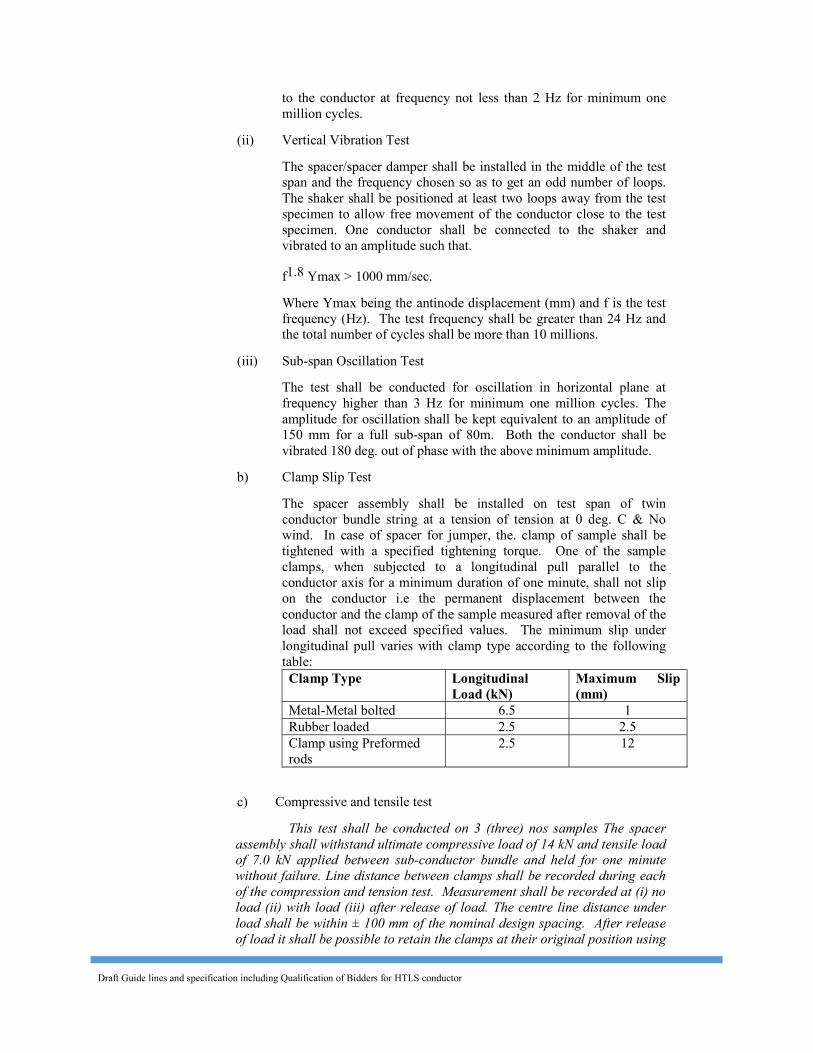
Draft Guide lines and specification including Qualification of Bidders for HTLS conductor
to the conductor at frequency not less than 2 Hz for minimum one million cycles.
(ii) Vertical Vibration Test The spacer/spacer damper shall be installed in the middle of the test
span and the frequency chosen so as to get an odd number of loops. The shaker shall be positioned at least two loops away from the test specimen to allow free movement of the conductor close to the test specimen. One conductor shall be connected to the shaker and vibrated to an amplitude such that.
f1.8 Ymax > 1000 mm/sec. Where Ymax being the antinode displacement (mm) and f is the test
frequency (Hz). The test frequency shall be greater than 24 Hz and the total number of cycles shall be more than 10 millions.
(iii) Sub-span Oscillation Test The test shall be conducted for oscillation in horizontal plane at
frequency higher than 3 Hz for minimum one million cycles. The amplitude for oscillation shall be kept equivalent to an amplitude of 150 mm for a full sub-span of 80m. Both the conductor shall be vibrated 180 deg. out of phase with the above minimum amplitude.
b) Clamp Slip Test The spacer assembly shall be installed on test span of twin conductor bundle string at a tension of tension at 0 deg. C & No wind. In case of spacer for jumper, the. clamp of sample shall be tightened with a specified tightening torque. One of the sample clamps, when subjected to a longitudinal pull parallel to the conductor axis for a minimum duration of one minute, shall not slip on the conductor i.e the permanent displacement between the conductor and the clamp of the sample measured after removal of the load shall not exceed specified values. The minimum slip under longitudinal pull varies with clamp type according to the following table: Clamp Type Longitudinal
Load (kN) Maximum Slip (mm)
Metal-Metal bolted 6.5 1 Rubber loaded 2.5 2.5 Clamp using Preformed rods
2.5 12 c) Compressive and tensile test This test shall be conducted on 3 (three) nos samples The spacer
assembly shall withstand ultimate compressive load of 14 kN and tensile load of 7.0 kN applied between sub-conductor bundle and held for one minute without failure. Line distance between clamps shall be recorded during each of the compression and tension test. Measurement shall be recorded at (i) no load (ii) with load (iii) after release of load. The centre line distance under load shall be within ± 100 mm of the nominal design spacing. After release of load it shall be possible to retain the clamps at their original position using
Draft Guide lines and specification including Qualification of Bidders for HTLS conductor
only slight hand pressure. There shall be no deformation or damage to the spacer assembly which would impair its function of maintaining the normal spacing.
d) Dynamic Characteristic Test (for Spacer Damper only) The purpose of this test is to obtain quantitative information
regarding the dynamic characteristics of the spacer damper. The values obtained during this test will serve as references to evaluate the behaviour of the same spacer damper under the fatigue test.
The test will consist in the application of sinusoidal movement of the spacer-damper articulation and measuring the force (F), displacement (X) and phase angle (Ø) between these two, from these values, the stiffness (K) and the damping factor (n) will be calculated.
F K = ——— Cos Ø; n = Tan Ø X The test frequency shall not be higher than 3 Hz. The test shall be
performed at five different displacement amplitudes. The amplitudes shall be selected to reproduce 10, 20, 40, 60 and 90 percent of the maximum displacement permitted by the spacer-damper design.
The test shall be performed on three samples. e) Fatigue Test (for Spacer Damper only) The purpose of this test is to evaluate the capacity of the spacer
damper to sustain without damage the cyclic movements which can be induced by vibrations.
The spacer damper articulation shall be subjected to cyclic motions for a total of 10 million cycles. The test frequency shall be between 2 and 3 Hz. The amplitude of motion shall be established on the following basis :
— the load applied on the spacer damper clamp shall not be less than ± 300 N.
— the clamp displacement under the applied load shall not be less than 60% of the maximum displacement permitted by the design.
— if the 300 N load generates movement exceeding the maximum permitted displacement, the load can be reduced to limit the movement to 95% of the maximum displacement.
— After the test, the sample shall be subjected to a second dynamic characteristic test. This test shall be performed at two amplitudes, 10% and 60% of the maximum displacement.
— The spacer damper shall show no signs of cracks or deterioration, loosening of bolts or abnormal wear.
The dynamic characteristics (k and n) shall not be less than 60% of the values measured before the fatigue test. The test shall be performed on three samples.
Draft Guide lines and specification including Qualification of Bidders for HTLS conductor
f) Ozone Test The test shall be performed in accordance with ASTM D-1171 by the
ozone chamber exposure method (method B). The test duration shall be 500 hours and the ozone concentration 50 PPHM. At the test completion, there shall be no visible crack under a 2xmagnification.
h) Log Decrement test (for spacer damper only) The spacer damper assembly shall be mounted on test span of
conductor bundle at a tension of 0 deg. C & no wind and ruling span of 400 m. The test span shall be instrumented to continuously monitor and record the horizontal motion of the sub-conductor in the sub-span between suspension point and the fist sample.
The log decrement test shall be made with an initial peak to peak amplitude of four to six times the conductor diameter in the middle of the sub-span being considered. The conductor shall be excited in a horizontal one loop per sub-span resonant mode with a slow and steady build up of amplitude that minimises harmonics and other distortions. After achieving a steady state motion, the conductor excitation shall be discontinued leaving the conductor undisturbed. The motion shall be recorded until it reduces to an amplitude of half of the conductor diameter. The logarithmic (log) decrement shall be the value for a minimum reduction of 80 % in amplitude. The minimum acceptable log decrement average for five or more excitation shall be 0.04 based upon the following formula for decay.
Loge An = 1 Loge A0 An+1 n A
Where A0 is the initial amplitude and An is the amplitude ‘n’ cycles later
2.4 Magnetic Power Loss Test for Spacer The sample involving ferrous parts shall be tested in a manner to simulate
service conditions for 50 Hz pure sine-wave. The test should be carried out at various currents ranging from 1200 to 1800 amperes per sub-conductor (for 400kV) the magnetic power loss at various currents should be specified in tabulated graphical form. The difference between the power losses without and with sample at room temperature shall be limited to value guaranteed by the supplier for --- Amperes current (rms) [at steady state conductor temperature]. The losses shall be determined by averaging the observations obtained from at least four samples.
2.5 Corona Extinction Voltage Test (Dry) [for 400kV] The sample when subjected to power frequency voltage shall have a corona
extinction voltage of not less than 320 kV rms line to ground under dry condition. There shall be no evidence of corona on any part of the sample. The atmospheric condition during testing shall be recorded and the test results shall be accordingly corrected with suitable correction factor as stipulated in IS:731- 1971.
2.6 Radio Interference Voltage Test (Dry) [for 400kV]
Draft Guide lines and specification including Qualification of Bidders for HTLS conductor
Under the conditions as specified under (3.8) above, the sample shall have a radio intertiference voltage level below 1000 microvolts at one MHz when subjected to 50 Hz AC voltage of 305 kV rms line to ground under dry condition. The test procedure shall be in accordance with IS:8263.
2.7 Chemical Analysis Test Chemical analysis of the material used for manufacture of items shall be
conducted to check the conformity of the same with Technical Specification and approved drawing.
3.0 Tests on All components (As applicable) 3.1 Chemical Analysis of Zinc used for Galvanizing Samples taken from the zinc ingot shall be chemically analysed as per IS-
209-1979. The purity of zinc shall not be less than 99.95%. 3.2 Tests for Forgings The chemical analysis hardness tests and magnetic particle inspection for
forgings, will be as per the internationally recognised procedures for these tests. The, sampling will be based on heat number and heat treatment batch. The details regarding test will be as discussed and mutually agreed to by the Contractor and Owner in Quality Assurance Programme.
3.3 Tests on Castings The chemical analysis, mechanical and metallographic tests and magnetic
particle inspection for castings will be as per the internationally recognised procedures for these tests. The samplings will be based on heat number and heat treatment batch. The details regarding test will be as discussed and mutually agreed to by the Contractor and Owner in Quality Assurance Programme.
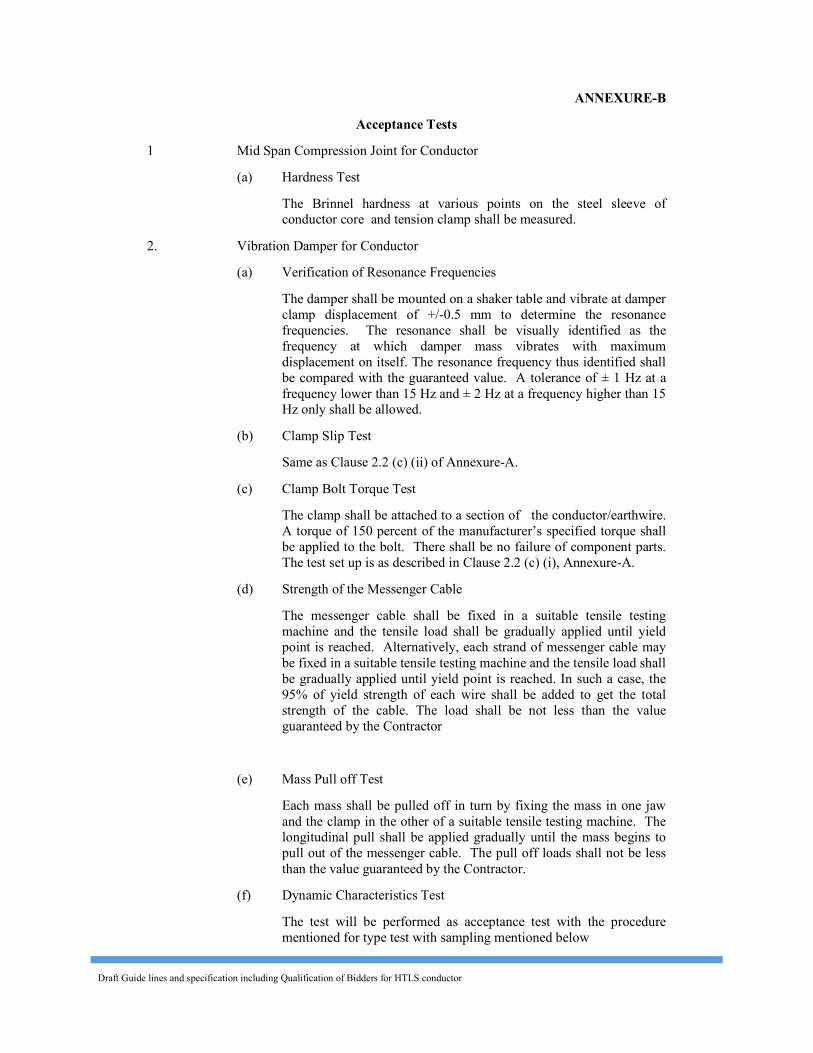
Draft Guide lines and specification including Qualification of Bidders for HTLS conductor
ANNEXURE-B Acceptance Tests
1 Mid Span Compression Joint for Conductor (a) Hardness Test The Brinnel hardness at various points on the steel sleeve of
conductor core and tension clamp shall be measured. 2. Vibration Damper for Conductor (a) Verification of Resonance Frequencies The damper shall be mounted on a shaker table and vibrate at damper
clamp displacement of +/-0.5 mm to determine the resonance frequencies. The resonance shall be visually identified as the frequency at which damper mass vibrates with maximum displacement on itself. The resonance frequency thus identified shall be compared with the guaranteed value. A tolerance of ± 1 Hz at a frequency lower than 15 Hz and ± 2 Hz at a frequency higher than 15 Hz only shall be allowed.
(b) Clamp Slip Test Same as Clause 2.2 (c) (ii) of Annexure-A. (c) Clamp Bolt Torque Test The clamp shall be attached to a section of the conductor/earthwire.
A torque of 150 percent of the manufacturer’s specified torque shall be applied to the bolt. There shall be no failure of component parts. The test set up is as described in Clause 2.2 (c) (i), Annexure-A.
(d) Strength of the Messenger Cable The messenger cable shall be fixed in a suitable tensile testing
machine and the tensile load shall be gradually applied until yield point is reached. Alternatively, each strand of messenger cable may be fixed in a suitable tensile testing machine and the tensile load shall be gradually applied until yield point is reached. In such a case, the 95% of yield strength of each wire shall be added to get the total strength of the cable. The load shall be not less than the value guaranteed by the Contractor
(e) Mass Pull off Test Each mass shall be pulled off in turn by fixing the mass in one jaw
and the clamp in the other of a suitable tensile testing machine. The longitudinal pull shall be applied gradually until the mass begins to pull out of the messenger cable. The pull off loads shall not be less than the value guaranteed by the Contractor.
(f) Dynamic Characteristics Test The test will be performed as acceptance test with the procedure
mentioned for type test with sampling mentioned below
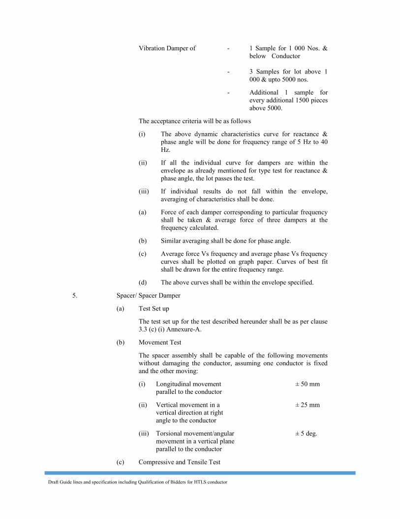
Draft Guide lines and specification including Qualification of Bidders for HTLS conductor
Vibration Damper of - 1 Sample for 1 000 Nos. & below Conductor
- 3 Samples for lot above 1 000 & upto 5000 nos.
- Additional 1 sample for every additional 1500 pieces above 5000.
The acceptance criteria will be as follows (i) The above dynamic characteristics curve for reactance &
phase angle will be done for frequency range of 5 Hz to 40 Hz.
(ii) If all the individual curve for dampers are within the envelope as already mentioned for type test for reactance & phase angle, the lot passes the test.
(iii) If individual results do not fall within the envelope, averaging of characteristics shall be done.
(a) Force of each damper corresponding to particular frequency shall be taken & average force of three dampers at the frequency calculated.
(b) Similar averaging shall be done for phase angle. (c) Average force Vs frequency and average phase Vs frequency
curves shall be plotted on graph paper. Curves of best fit shall be drawn for the entire frequency range.
(d) The above curves shall be within the envelope specified. 5. Spacer/ Spacer Damper (a) Test Set up The test set up for the test described hereunder shall be as per clause
3.3 (c) (i) Annexure-A. (b) Movement Test The spacer assembly shall be capable of the following movements
without damaging the conductor, assuming one conductor is fixed and the other moving:
(i) Longitudinal movement ± 50 mm parallel to the conductor (ii) Vertical movement in a ± 25 mm vertical direction at right angle to the conductor (iii) Torsional movement/angular ± 5 deg. movement in a vertical plane parallel to the conductor (c) Compressive and Tensile Test
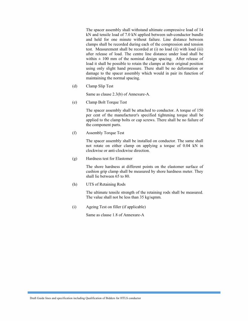
Draft Guide lines and specification including Qualification of Bidders for HTLS conductor
The spacer assembly shall withstand ultimate compressive load of 14 kN and tensile load of 7.0 kN applied between sub-conductor bundle and held for one minute without failure. Line distance between clamps shall be recorded during each of the compression and tension test. Measurement shall be recorded at (i) no load (ii) with load (iii) after release of load. The centre line distance under load shall be within ± 100 mm of the nominal design spacing. After release of load it shall be possible to retain the clamps at their original position using only slight hand pressure. There shall be no deformation or damage to the spacer assembly which would in pair its function of maintaining the normal spacing.
(d) Clamp Slip Test Same as clause 2.3(b) of Annexure-A. (e) Clamp Bolt Torque Test The spacer assembly shall be attached to conductor. A torque of 150
per cent of the manufacturer's specified tightening torque shall be applied to the clamp bolts or cap screws. There shall be no failure of the component parts.
(f) Assembly Torque Test The spacer assembly shall be installed on conductor. The same shall
not rotate on either clamp on applying a torque of 0.04 kN in clockwise or anti-clockwise direction.
(g) Hardness test for Elastomer The shore hardness at different points on the elastomer surface of
cushion grip clamp shall be measured by shore hardness meter. They shall lie between 65 to 80.
(h) UTS of Retaining Rods The ultimate tensile strength of the retaining rods shall be measured.
The value shall not be less than 35 kg/sqmm. (i) Ageing Test on filler (if applicable) Same as clause 1.8 of Annexure-A
Draft Guide lines and specification including Qualification of Bidders for HTLS conductor
SECTION-VI
TECHNICAL DATA SHEETS FOR
HTLS CONDUCTOR AND
HARDWARE FITTINGS & ACCESSORIES
Draft Guide lines and specification including Qualification of Bidders for HTLS conductor
SECTION -VI TECHNICAL DATA SHEETS FOR HTLS CONDUCTOR
AND HARDWARE FITTINGS & ACCESSORIES
CONTENTS Schedule – 1 HTLS conductor Schedule – 2 Suspension Clamp for HTLS Conductor Schedule – 3 Dead End clamp for HTLS Conductor Schedule – 4 Mid Span Compression Joint for HTLS Conductor Schedule – 5 Repair sleeve for HTLS Conductor Schedule – 6 Vibration Damper for HTLS Conductor Schedule – 7 Bundle Spacer for HTLS Conductor Schedule – 8 Rigid Spacer for HTLS Conductor Schedule – 9 Spacer Damper for HTLS Conductor
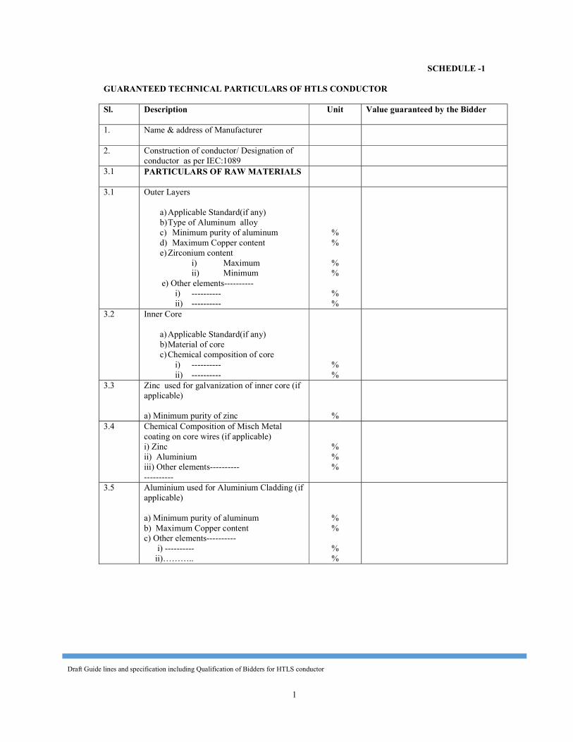
Draft Guide lines and specification including Qualification of Bidders for HTLS conductor
1
SCHEDULE -1 GUARANTEED TECHNICAL PARTICULARS OF HTLS CONDUCTOR Sl. Description Unit Value guaranteed by the Bidder 1. Name & address of Manufacturer
2. Construction of conductor/ Designation of conductor as per IEC:1089
3.1 PARTICULARS OF RAW MATERIALS
3.1 Outer Layers
a) Applicable Standard(if any) b) Type of Aluminum alloy c) Minimum purity of aluminum d) Maximum Copper content e) Zirconium content
i) Maximum ii) Minimum
e) Other elements---------- i) ---------- ii) ----------
% %
% %
% %
3.2 Inner Core
a) Applicable Standard(if any) b) Material of core c) Chemical composition of core
i) ---------- ii) ----------
% %
3.3 Zinc used for galvanization of inner core (if applicable) a) Minimum purity of zinc
%
3.4 Chemical Composition of Misch Metal coating on core wires (if applicable) i) Zinc ii) Aluminium iii) Other elements---------- ----------
% % %
3.5 Aluminium used for Aluminium Cladding (if applicable) a) Minimum purity of aluminum b) Maximum Copper content c) Other elements---------- i) ---------- ii)………..
% %
% %
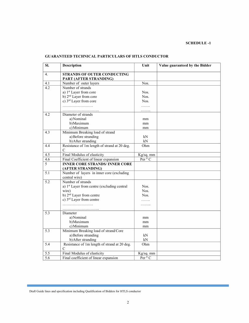
Draft Guide lines and specification including Qualification of Bidders for HTLS conductor
2
SCHEDULE -1 GUARANTEED TECHNICAL PARTICULARS OF HTLS CONDUCTOR Sl. Description Unit Value guaranteed by the Bidder 4. STRANDS OF OUTER CONDUCTING
PART (AFTER STRANDING)
4.1 Number of outer layers Nos. 4.2 Number of strands
a) 1st Layer from core b) 2nd Layer from core c) 3rd Layer from core …………………… ………………………..
Nos. Nos. Nos. ……. ……..
4.2 Diameter of strands a) Nominal b) Maximum c) Minimum
mm mm mm
4.3 Minimum Breaking load of strand a) Before stranding b) After stranding
kN kN
4.4 Resistance of 1m length of strand at 20 deg. C
Ohm 4.5 Final Modulus of elasticity Kg/sq. mm 4.6 Final Coefficient of linear expansion Per 0 C 5 INNER CORE STRANDS/ INNER CORE
(AFTER STRANDING)
5.1 Number of layers in inner core (excluding central wire)
5.2 Number of strands
a) 1st Layer from centre (excluding central wire) b) 2nd Layer from centre c) 3rd Layer from centre …………………… ………………………..
Nos. Nos. Nos. ……. ……..
5.3 Diameter a) Nominal b) Maximum c) Minimum
mm mm mm
5.3 Minimum Breaking load of strand/Core a) Before stranding b) After stranding
kN kN
5.4 Resistance of 1m length of strand at 20 deg. C
Ohm 5.5 Final Modulus of elasticity Kg/sq. mm 5.6 Final coefficient of linear expansion Per 0 C
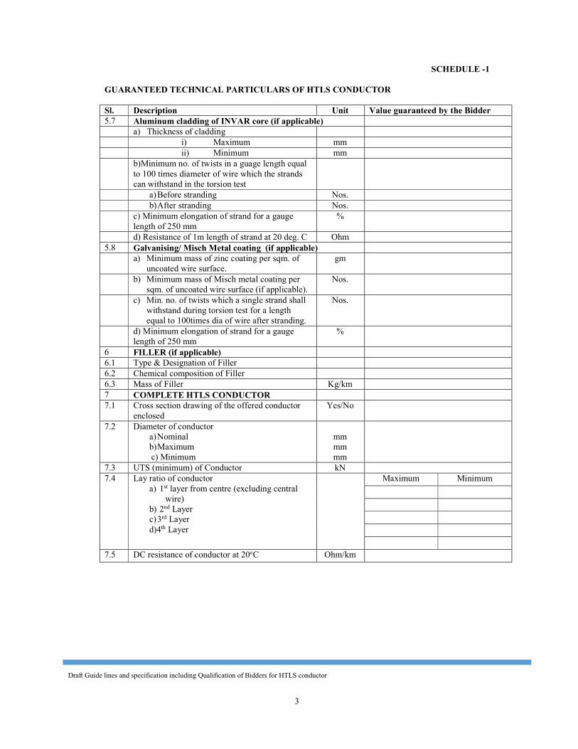
Draft Guide lines and specification including Qualification of Bidders for HTLS conductor
3
SCHEDULE -1
GUARANTEED TECHNICAL PARTICULARS OF HTLS CONDUCTOR Sl. Description Unit Value guaranteed by the Bidder 5.7 Aluminum cladding of INVAR core (if applicable) a) Thickness of cladding i) Maximum mm ii) Minimum mm b)Minimum no. of twists in a guage length equal
to 100 times diameter of wire which the strands can withstand in the torsion test
a) Before stranding Nos. b) After stranding Nos. c) Minimum elongation of strand for a gauge
length of 250 mm %
d) Resistance of 1m length of strand at 20 deg. C Ohm 5.8 Galvanising/ Misch Metal coating (if applicable) a) Minimum mass of zinc coating per sqm. of
uncoated wire surface. gm
b) Minimum mass of Misch metal coating per sqm. of uncoated wire surface (if applicable).
Nos.
c) Min. no. of twists which a single strand shall
withstand during torsion test for a length equal to 100times dia of wire after stranding.
Nos.
d) Minimum elongation of strand for a gauge length of 250 mm
% 6 FILLER (if applicable) 6.1 Type & Designation of Filler 6.2 Chemical composition of Filler 6.3 Mass of Filler Kg/km 7 COMPLETE HTLS CONDUCTOR 7.1 Cross section drawing of the offered conductor
enclosed Yes/No
7.2 Diameter of conductor a) Nominal b) Maximum
c) Minimum
mm mm mm
7.3 UTS (minimum) of Conductor kN 7.4 Lay ratio of conductor
a) 1st layer from centre (excluding central wire)
b) 2nd Layer c) 3rd Layer d)4th Layer
Maximum Minimum
7.5 DC resistance of conductor at 20oC Ohm/km
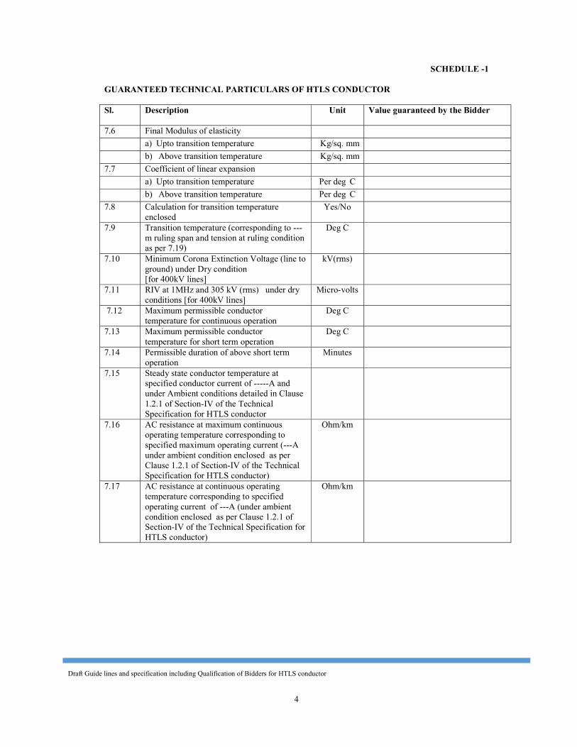
Draft Guide lines and specification including Qualification of Bidders for HTLS conductor
4
SCHEDULE -1 GUARANTEED TECHNICAL PARTICULARS OF HTLS CONDUCTOR Sl. Description Unit Value guaranteed by the Bidder 7.6 Final Modulus of elasticity a) Upto transition temperature Kg/sq. mm b) Above transition temperature Kg/sq. mm 7.7 Coefficient of linear expansion a) Upto transition temperature Per deg C b) Above transition temperature Per deg C 7.8 Calculation for transition temperature
enclosed Yes/No
7.9 Transition temperature (corresponding to ---m ruling span and tension at ruling condition as per 7.19)
Deg C
7.10 Minimum Corona Extinction Voltage (line to ground) under Dry condition [for 400kV lines]
kV(rms)
7.11 RIV at 1MHz and 305 kV (rms) under dry conditions [for 400kV lines]
Micro-volts 7.12 Maximum permissible conductor
temperature for continuous operation Deg C
7.13 Maximum permissible conductor temperature for short term operation
Deg C 7.14 Permissible duration of above short term
operation Minutes
7.15 Steady state conductor temperature at specified conductor current of -----A and under Ambient conditions detailed in Clause 1.2.1 of Section-IV of the Technical Specification for HTLS conductor
7.16 AC resistance at maximum continuous operating temperature corresponding to specified maximum operating current (---A under ambient condition enclosed as per Clause 1.2.1 of Section-IV of the Technical Specification for HTLS conductor)
Ohm/km
7.17 AC resistance at continuous operating temperature corresponding to specified operating current of ---A (under ambient condition enclosed as per Clause 1.2.1 of Section-IV of the Technical Specification for HTLS conductor)
Ohm/km
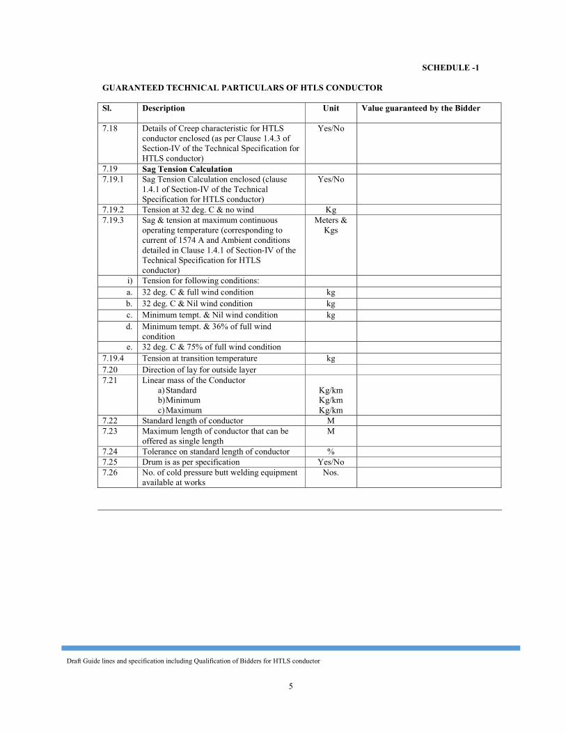
Draft Guide lines and specification including Qualification of Bidders for HTLS conductor
5
SCHEDULE -1 GUARANTEED TECHNICAL PARTICULARS OF HTLS CONDUCTOR Sl. Description Unit Value guaranteed by the Bidder 7.18 Details of Creep characteristic for HTLS
conductor enclosed (as per Clause 1.4.3 of Section-IV of the Technical Specification for HTLS conductor)
Yes/No
7.19 Sag Tension Calculation 7.19.1 Sag Tension Calculation enclosed (clause
1.4.1 of Section-IV of the Technical Specification for HTLS conductor)
Yes/No
7.19.2 Tension at 32 deg. C & no wind Kg 7.19.3 Sag & tension at maximum continuous
operating temperature (corresponding to current of 1574 A and Ambient conditions detailed in Clause 1.4.1 of Section-IV of the Technical Specification for HTLS conductor)
Meters & Kgs
i) Tension for following conditions: a. 32 deg. C & full wind condition kg b. 32 deg. C & Nil wind condition kg c. Minimum tempt. & Nil wind condition kg d. Minimum tempt. & 36% of full wind
condition
e. 32 deg. C & 75% of full wind condition 7.19.4 Tension at transition temperature kg 7.20 Direction of lay for outside layer 7.21 Linear mass of the Conductor
a) Standard b) Minimum c) Maximum
Kg/km Kg/km Kg/km
7.22 Standard length of conductor M 7.23 Maximum length of conductor that can be
offered as single length M
7.24 Tolerance on standard length of conductor % 7.25 Drum is as per specification Yes/No 7.26 No. of cold pressure butt welding equipment
available at works Nos.
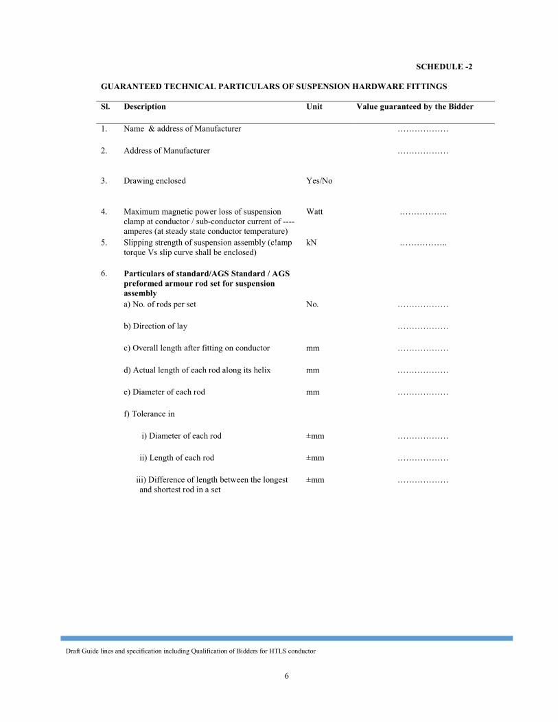
Draft Guide lines and specification including Qualification of Bidders for HTLS conductor
6
SCHEDULE -2 GUARANTEED TECHNICAL PARTICULARS OF SUSPENSION HARDWARE FITTINGS Sl. Description Unit Value guaranteed by the Bidder 1. Name & address of Manufacturer ……………… 2. Address of Manufacturer ………………
3. Drawing enclosed Yes/No
4. Maximum magnetic power loss of suspension clamp at conductor / sub-conductor current of ---- amperes (at steady state conductor temperature)
Watt ……………..
5. Slipping strength of suspension assembly (c!amp torque Vs slip curve shall be enclosed)
kN ……………..
6. Particulars of standard/AGS Standard / AGS preformed armour rod set for suspension assembly
a) No. of rods per set No. ……………… b) Direction of lay ……………… c) Overall length after fitting on conductor mm ……………… d) Actual length of each rod along its helix mm ……………… e) Diameter of each rod mm ……………… f) Tolerance in i) Diameter of each rod ±mm ……………… ii) Length of each rod ±mm ……………… iii) Difference of length between the longest
and shortest rod in a set ±mm ………………
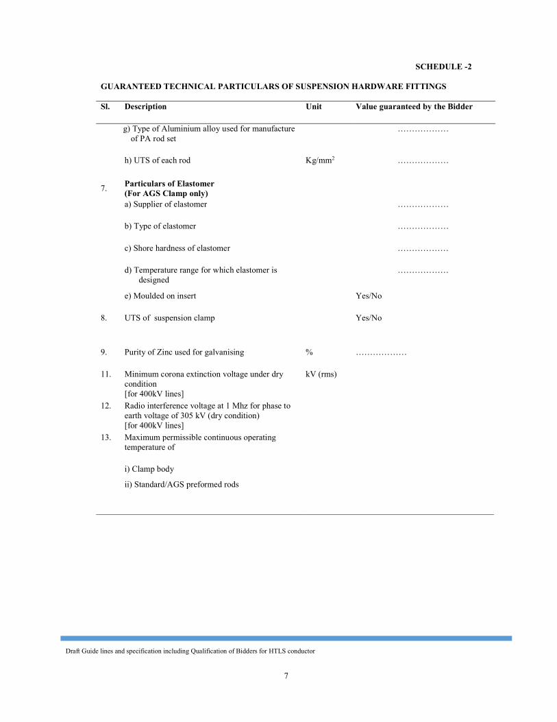
Draft Guide lines and specification including Qualification of Bidders for HTLS conductor
7
SCHEDULE -2
GUARANTEED TECHNICAL PARTICULARS OF SUSPENSION HARDWARE FITTINGS Sl. Description Unit Value guaranteed by the Bidder g) Type of Aluminium alloy used for manufacture
of PA rod set ………………
h) UTS of each rod Kg/mm2 ………………
7. Particulars of Elastomer (For AGS Clamp only)
a) Supplier of elastomer ……………… b) Type of elastomer ……………… c) Shore hardness of elastomer ……………… d) Temperature range for which elastomer is
designed ………………
e) Moulded on insert Yes/No 8. UTS of suspension clamp Yes/No
9. Purity of Zinc used for galvanising % ……………… 11. Minimum corona extinction voltage under dry
condition [for 400kV lines]
kV (rms)
12. Radio interference voltage at 1 Mhz for phase to earth voltage of 305 kV (dry condition) [for 400kV lines]
13. Maximum permissible continuous operating temperature of
i) Clamp body ii) Standard/AGS preformed rods
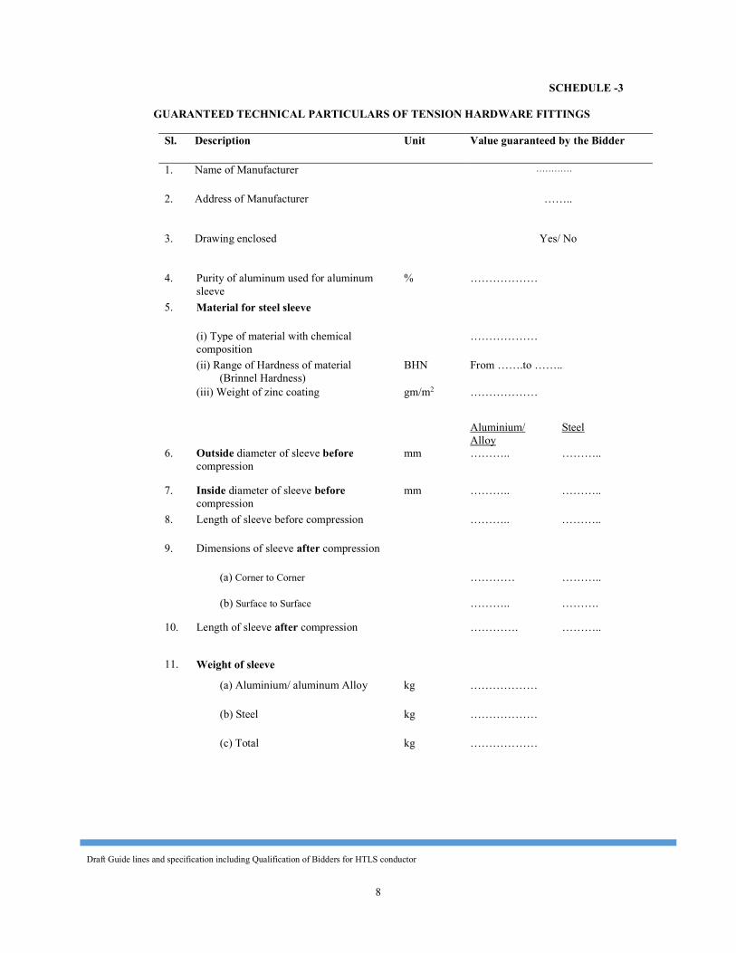
Draft Guide lines and specification including Qualification of Bidders for HTLS conductor
8
SCHEDULE -3
GUARANTEED TECHNICAL PARTICULARS OF TENSION HARDWARE FITTINGS
Sl. Description Unit Value guaranteed by the Bidder
1. Name of Manufacturer …………
2. Address of Manufacturer ……..
3. Drawing enclosed Yes/ No
4. Purity of aluminum used for aluminum sleeve
% ……………… 5. Material for steel sleeve (i) Type of material with chemical
composition ………………
(ii) Range of Hardness of material
(Brinnel Hardness) BHN From …….to ……..
(iii) Weight of zinc coating gm/m2 ………………
Aluminium/ Alloy
Steel 6. Outside diameter of sleeve before
compression mm ……….. ………..
7. Inside diameter of sleeve before compression
mm ……….. ……….. 8. Length of sleeve before compression ……….. ……….. 9. Dimensions of sleeve after compression
(a) Corner to Corner ………… ……….. (b) Surface to Surface ……….. ………. 10. Length of sleeve after compression …………. ………..
11. Weight of sleeve (a) Aluminium/ aluminum Alloy kg ……………… (b) Steel kg ……………… (c) Total kg ………………
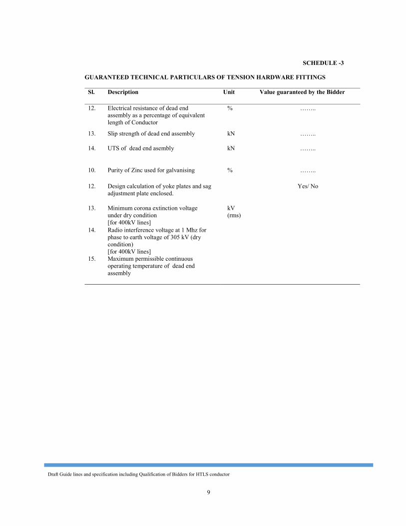
Draft Guide lines and specification including Qualification of Bidders for HTLS conductor
9
SCHEDULE -3 GUARANTEED TECHNICAL PARTICULARS OF TENSION HARDWARE FITTINGS
Sl. Description Unit Value guaranteed by the Bidder
12. Electrical resistance of dead end
assembly as a percentage of equivalent length of Conductor
% ……..
13. Slip strength of dead end assembly kN …….. 14. UTS of dead end asembly kN ……..
10. Purity of Zinc used for galvanising % …….. 12. Design calculation of yoke plates and sag
adjustment plate enclosed. Yes/ No
13. Minimum corona extinction voltage
under dry condition [for 400kV lines]
kV (rms)
14. Radio interference voltage at 1 Mhz for phase to earth voltage of 305 kV (dry condition) [for 400kV lines]
15. Maximum permissible continuous operating temperature of dead end assembly
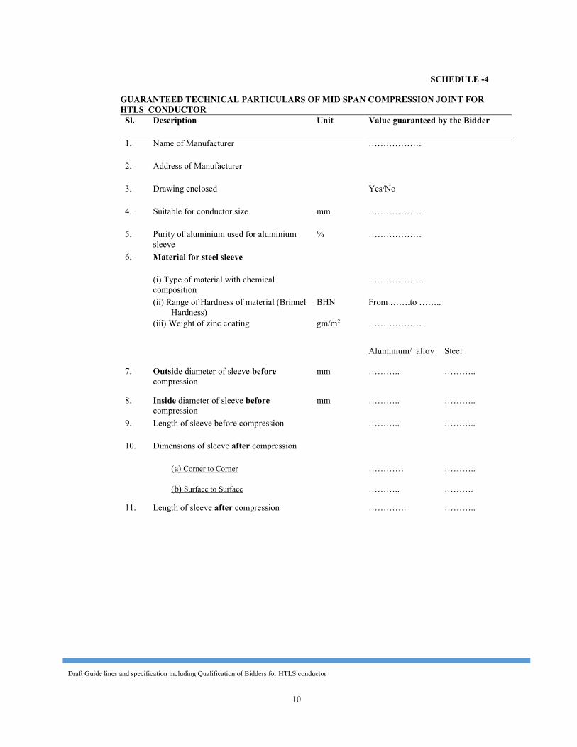
Draft Guide lines and specification including Qualification of Bidders for HTLS conductor
10
SCHEDULE -4
GUARANTEED TECHNICAL PARTICULARS OF MID SPAN COMPRESSION JOINT FOR HTLS CONDUCTOR
Sl. Description Unit Value guaranteed by the Bidder 1. Name of Manufacturer ………………
2. Address of Manufacturer 3. Drawing enclosed Yes/No 4. Suitable for conductor size mm ……………… 5. Purity of aluminium used for aluminium
sleeve % ………………
6. Material for steel sleeve (i) Type of material with chemical
composition ………………
(ii) Range of Hardness of material (Brinnel
Hardness) BHN From …….to ……..
(iii) Weight of zinc coating gm/m2 ………………
Aluminium/ alloy Steel 7. Outside diameter of sleeve before
compression mm ……….. ………..
8. Inside diameter of sleeve before compression
mm ……….. ……….. 9. Length of sleeve before compression ……….. ……….. 10. Dimensions of sleeve after compression
(a) Corner to Corner ………… ……….. (b) Surface to Surface ……….. ………. 11. Length of sleeve after compression …………. ………..
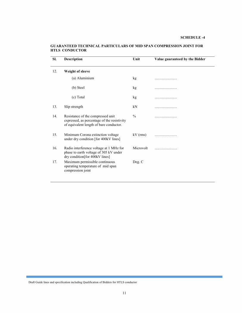
Draft Guide lines and specification including Qualification of Bidders for HTLS conductor
11
SCHEDULE -4 GUARANTEED TECHNICAL PARTICULARS OF MID SPAN COMPRESSION JOINT FOR HTLS CONDUCTOR
Sl. Description Unit Value guaranteed by the Bidder
12. Weight of sleeve (a) Aluminium kg ……………… (b) Steel kg ……………… (c) Total kg ……………… 13. Slip strength kN ……………… 14. Resistance of the compressed unit
expressed, as percentage of the resistivity of equivalent length of bare conductor.
% ………………
15. Minimum Corona extinction voltage under dry condition [for 400kV lines]
kV (rms) ………………
16. Radio interference voltage at 1 MHz for phase to earth voltage of 305 kV under dry condition[for 400kV lines]
Microvolt ………………
17. Maximum permissible continuous operating temperature of mid span compression joint
Deg. C
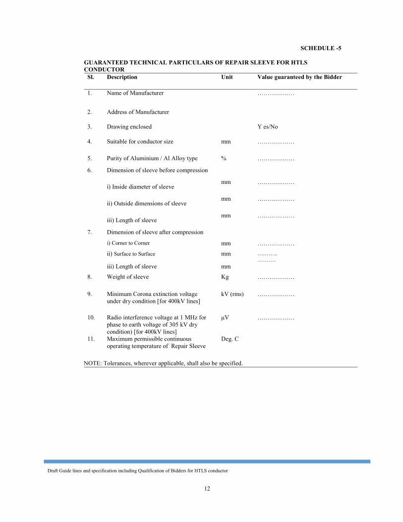
Draft Guide lines and specification including Qualification of Bidders for HTLS conductor
12
SCHEDULE -5
GUARANTEED TECHNICAL PARTICULARS OF REPAIR SLEEVE FOR HTLS CONDUCTOR
Sl. Description Unit Value guaranteed by the Bidder 1. Name of Manufacturer ………………
2. Address of Manufacturer 3. Drawing enclosed Y es/No 4. Suitable for conductor size mm ………………
5. Purity of Aluminium / Al Alloy type % ……………… 6. Dimension of sleeve before compression i) Inside diameter of sleeve mm ………………
ii) Outside dimensions of sleeve mm ………………
iii) Length of sleeve mm ……………… 7. Dimension of sleeve after compression i) Corner to Corner mm ……………… ii) Surface to Surface mm ………..
………. iii) Length of sleeve mm 8. Weight of sleeve Kg ……………… 9. Minimum Corona extinction voltage
under dry condition [for 400kV lines] kV (rms) ………………
10. Radio interference voltage at 1 MHz for phase to earth voltage of 305 kV dry condition) [for 400kV lines]
μV ………………
11. Maximum permissible continuous operating temperature of Repair Sleeve
Deg. C NOTE: Tolerances, wherever applicable, shall also be specified.
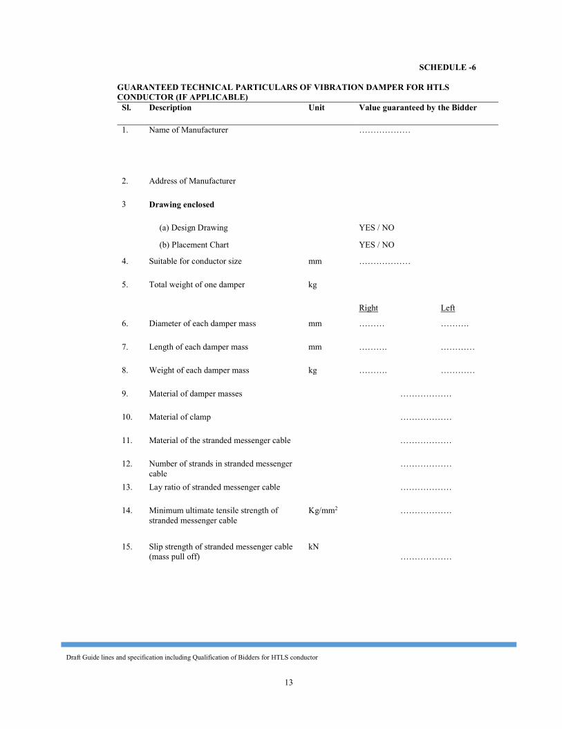
Draft Guide lines and specification including Qualification of Bidders for HTLS conductor
13
SCHEDULE -6 GUARANTEED TECHNICAL PARTICULARS OF VIBRATION DAMPER FOR HTLS CONDUCTOR (IF APPLICABLE)
Sl. Description Unit Value guaranteed by the Bidder 1. Name of Manufacturer ………………
2. Address of Manufacturer 3 Drawing enclosed (a) Design Drawing YES / NO (b) Placement Chart YES / NO 4. Suitable for conductor size mm ……………… 5. Total weight of one damper kg Right Left 6. Diameter of each damper mass mm ……… ………. 7. Length of each damper mass mm ………. ………… 8. Weight of each damper mass kg ………. ………… 9. Material of damper masses ……………… 10. Material of clamp ……………… 11. Material of the stranded messenger cable ……………… 12. Number of strands in stranded messenger
cable ………………
13. Lay ratio of stranded messenger cable ……………… 14. Minimum ultimate tensile strength of
stranded messenger cable Kg/mm2 ………………
15. Slip strength of stranded messenger cable (mass pull off)
kN ………………
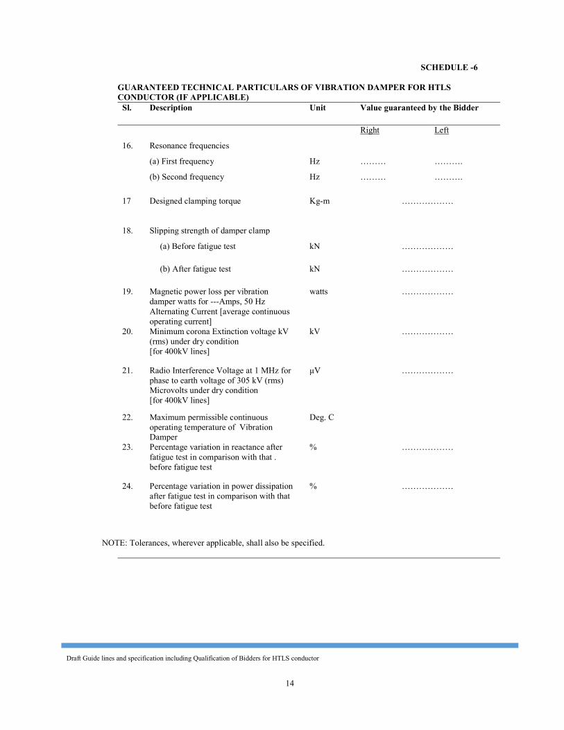
Draft Guide lines and specification including Qualification of Bidders for HTLS conductor
14
SCHEDULE -6 GUARANTEED TECHNICAL PARTICULARS OF VIBRATION DAMPER FOR HTLS CONDUCTOR (IF APPLICABLE)
Sl. Description Unit Value guaranteed by the Bidder Right Left 16. Resonance frequencies (a) First frequency Hz ……… ………. (b) Second frequency Hz ……… ………. 17 Designed clamping torque Kg-m ………………
18. Slipping strength of damper clamp (a) Before fatigue test kN ……………… (b) After fatigue test kN ……………… 19. Magnetic power loss per vibration
damper watts for ---Amps, 50 Hz Alternating Current [average continuous operating current]
watts ………………
20. Minimum corona Extinction voltage kV (rms) under dry condition [for 400kV lines]
kV ………………
21. Radio Interference Voltage at 1 MHz for phase to earth voltage of 305 kV (rms) Microvolts under dry condition [for 400kV lines]
μV ………………
22. Maximum permissible continuous operating temperature of Vibration Damper
Deg. C
23. Percentage variation in reactance after fatigue test in comparison with that . before fatigue test
% ………………
24. Percentage variation in power dissipation after fatigue test in comparison with that before fatigue test
% ………………
NOTE: Tolerances, wherever applicable, shall also be specified.
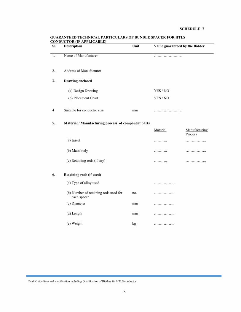
Draft Guide lines and specification including Qualification of Bidders for HTLS conductor
15
SCHEDULE -7 GUARANTEED TECHNICAL PARTICULARS OF BUNDLE SPACER FOR HTLS CONDUCTOR (IF APPLICABLE)
Sl. Description Unit Value guaranteed by the Bidder 1. Name of Manufacturer …………………..
2. Address of Manufacturer 3. Drawing enclosed (a) Design Drawing YES / NO (b) Placement Chart YES / NO
4 Suitable for conductor size mm …………………..
5. Material / Manufacturing process of component parts Material Manufacturing
Process (a) Insert ……….. …………….. (b) Main body ……….. …………….. (c) Retaining rods (if any) ……….. ……………..
6. Retaining rods (if used)
(a) Type of alloy used …………….. (b) Number of retaining rods used for
each spacer no. ……………..
(c) Diameter mm …………….. (d) Length mm …………….. (e) Weight kg ……………..
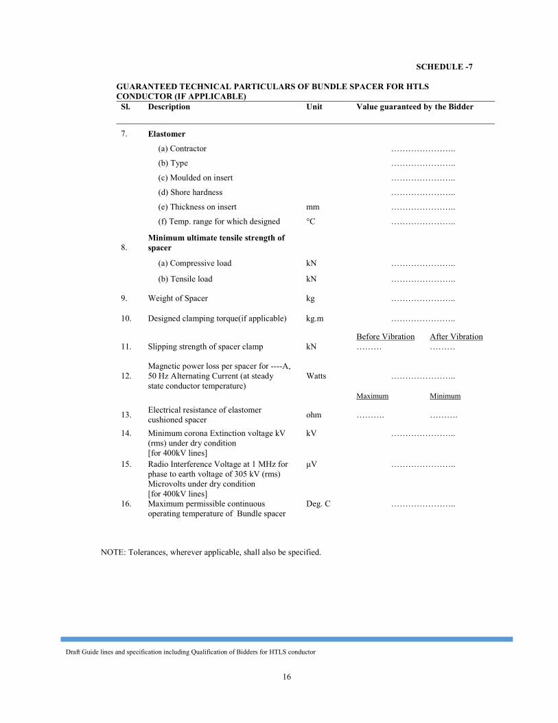
Draft Guide lines and specification including Qualification of Bidders for HTLS conductor
16
SCHEDULE -7
GUARANTEED TECHNICAL PARTICULARS OF BUNDLE SPACER FOR HTLS CONDUCTOR (IF APPLICABLE)
Sl. Description Unit Value guaranteed by the Bidder
7. Elastomer (a) Contractor ………………….. (b) Type ………………….. (c) Moulded on insert ………………….. (d) Shore hardness ………………….. (e) Thickness on insert mm ………………….. (f) Temp. range for which designed °C …………………..
8. Minimum ultimate tensile strength of spacer
(a) Compressive load kN ………………….. (b) Tensile load kN ………………….. 9. Weight of Spacer kg ………………….. 10. Designed clamping torque(if applicable) kg.m ………………….. Before Vibration After Vibration 11. Slipping strength of spacer clamp kN ……… ………
12. Magnetic power loss per spacer for ----A, 50 Hz Alternating Current (at steady state conductor temperature)
Watts ………………….. Maximum Minimum 13. Electrical resistance of elastomer
cushioned spacer ohm ………. ………. 14. Minimum corona Extinction voltage kV
(rms) under dry condition [for 400kV lines]
kV …………………..
15. Radio Interference Voltage at 1 MHz for phase to earth voltage of 305 kV (rms) Microvolts under dry condition [for 400kV lines]
μV …………………..
16. Maximum permissible continuous operating temperature of Bundle spacer
Deg. C …………………..
NOTE: Tolerances, wherever applicable, shall also be specified.
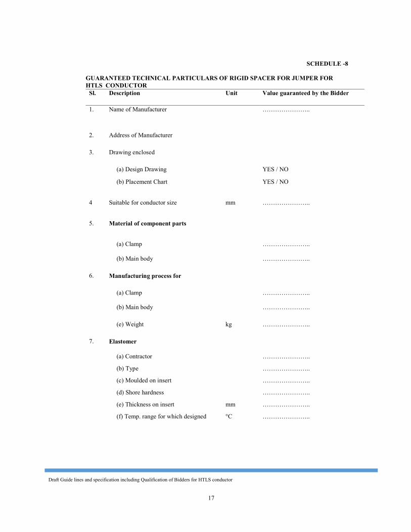
Draft Guide lines and specification including Qualification of Bidders for HTLS conductor
17
SCHEDULE -8 GUARANTEED TECHNICAL PARTICULARS OF RIGID SPACER FOR JUMPER FOR HTLS CONDUCTOR
Sl. Description Unit Value guaranteed by the Bidder 1. Name of Manufacturer …………………..
2. Address of Manufacturer 3. Drawing enclosed (a) Design Drawing YES / NO (b) Placement Chart YES / NO
4 Suitable for conductor size mm …………………..
5. Material of component parts
(a) Clamp …………………..
(b) Main body …………………..
6. Manufacturing process for (a) Clamp …………………..
(b) Main body …………………..
(e) Weight kg …………………..
7. Elastomer (a) Contractor ………………….. (b) Type ………………….. (c) Moulded on insert ………………….. (d) Shore hardness ………………….. (e) Thickness on insert mm ………………….. (f) Temp. range for which designed °C …………………..
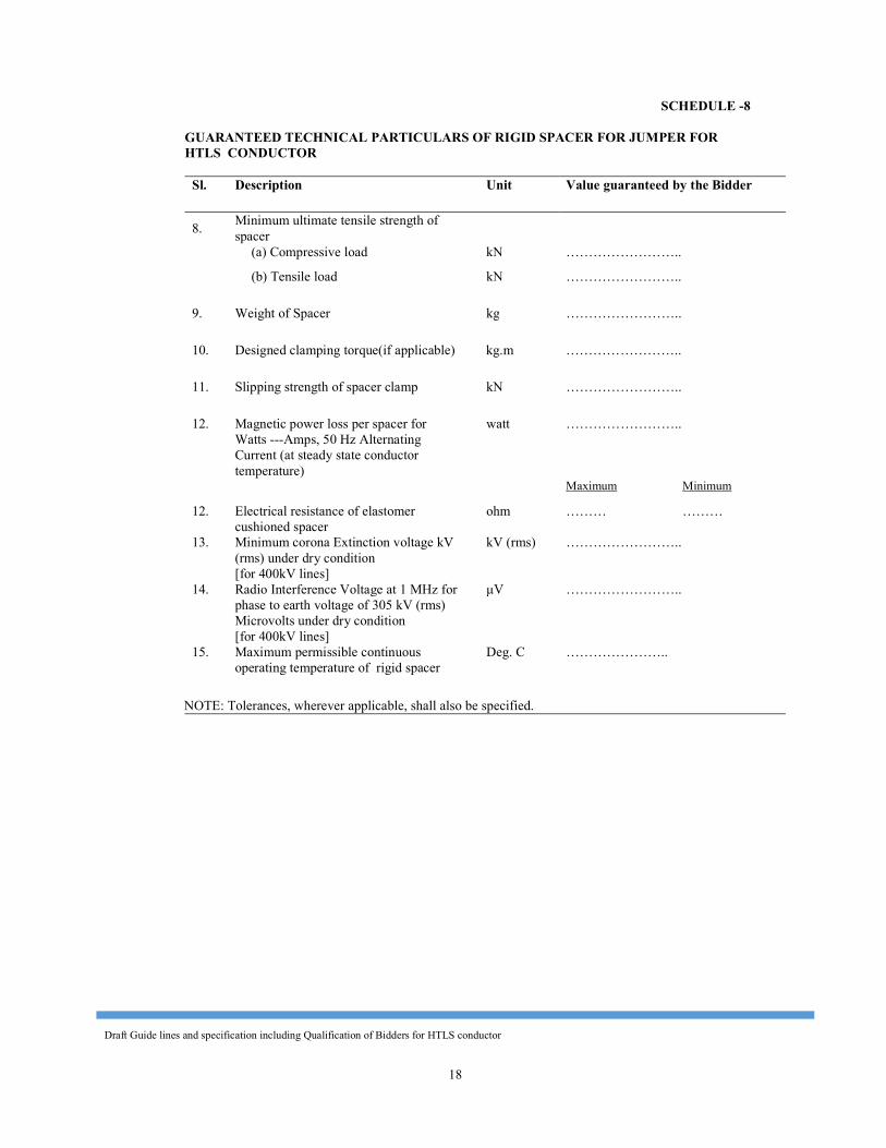
Draft Guide lines and specification including Qualification of Bidders for HTLS conductor
18
SCHEDULE -8
GUARANTEED TECHNICAL PARTICULARS OF RIGID SPACER FOR JUMPER FOR HTLS CONDUCTOR
Sl. Description Unit Value guaranteed by the Bidder
8. Minimum ultimate tensile strength of spacer
(a) Compressive load kN …………………….. (b) Tensile load kN …………………….. 9. Weight of Spacer kg …………………….. 10. Designed clamping torque(if applicable) kg.m …………………….. 11. Slipping strength of spacer clamp kN …………………….. 12. Magnetic power loss per spacer for
Watts ---Amps, 50 Hz Alternating Current (at steady state conductor temperature)
watt ……………………..
Maximum Minimum 12. Electrical resistance of elastomer
cushioned spacer ohm ……… ………
13. Minimum corona Extinction voltage kV (rms) under dry condition [for 400kV lines]
kV (rms) ……………………..
14. Radio Interference Voltage at 1 MHz for phase to earth voltage of 305 kV (rms) Microvolts under dry condition [for 400kV lines]
μV ……………………..
15. Maximum permissible continuous operating temperature of rigid spacer
Deg. C ………………….. NOTE: Tolerances, wherever applicable, shall also be specified.
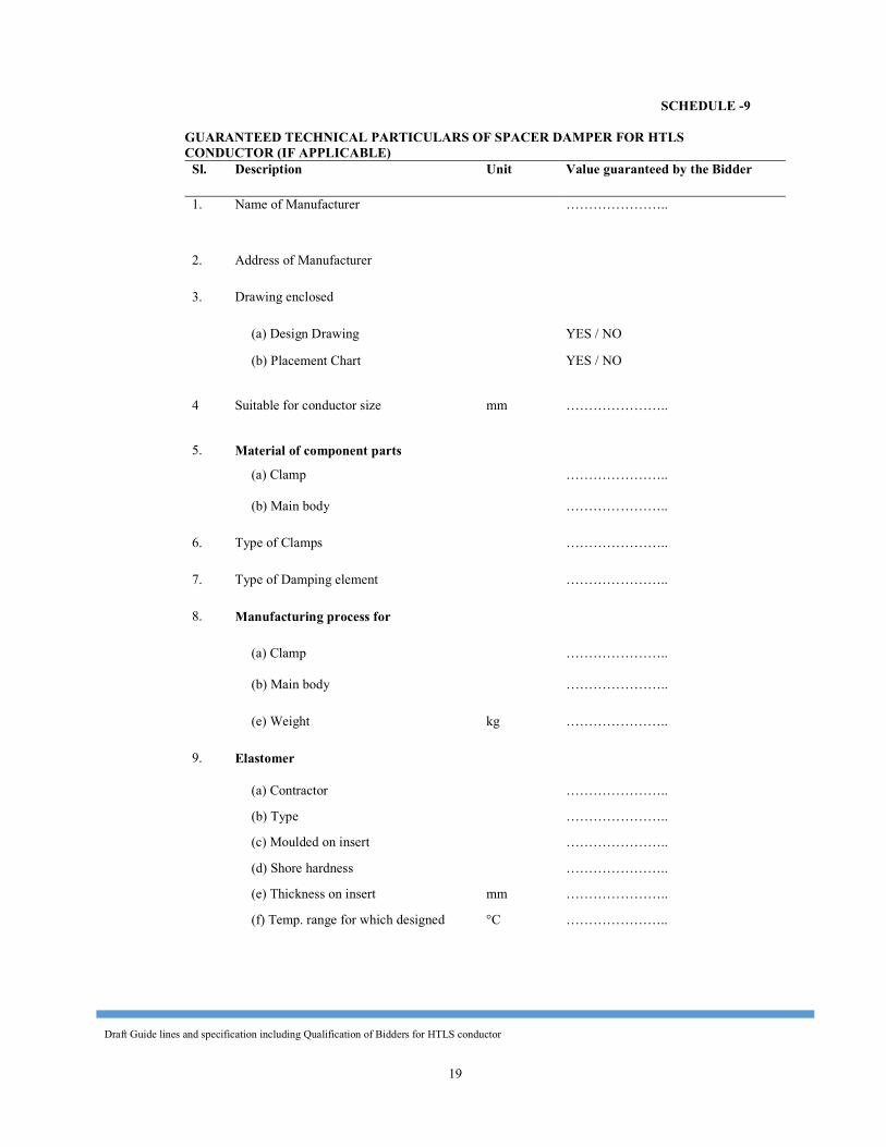
Draft Guide lines and specification including Qualification of Bidders for HTLS conductor
19
SCHEDULE -9
GUARANTEED TECHNICAL PARTICULARS OF SPACER DAMPER FOR HTLS CONDUCTOR (IF APPLICABLE)
Sl. Description Unit Value guaranteed by the Bidder 1. Name of Manufacturer …………………..
2. Address of Manufacturer 3. Drawing enclosed (a) Design Drawing YES / NO (b) Placement Chart YES / NO
4 Suitable for conductor size mm …………………..
5. Material of component parts (a) Clamp …………………..
(b) Main body …………………..
6. Type of Clamps …………………..
7. Type of Damping element …………………..
8. Manufacturing process for (a) Clamp …………………..
(b) Main body …………………..
(e) Weight kg …………………..
9. Elastomer (a) Contractor ………………….. (b) Type ………………….. (c) Moulded on insert ………………….. (d) Shore hardness ………………….. (e) Thickness on insert mm ………………….. (f) Temp. range for which designed °C …………………..
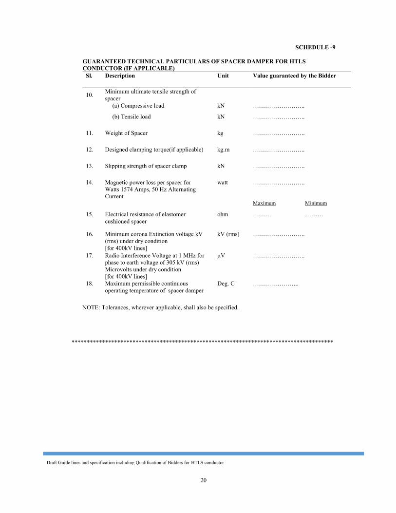
Draft Guide lines and specification including Qualification of Bidders for HTLS conductor
20
SCHEDULE -9 GUARANTEED TECHNICAL PARTICULARS OF SPACER DAMPER FOR HTLS CONDUCTOR (IF APPLICABLE)
Sl. Description Unit Value guaranteed by the Bidder
10. Minimum ultimate tensile strength of spacer
(a) Compressive load kN …………………….. (b) Tensile load kN …………………….. 11. Weight of Spacer kg …………………….. 12. Designed clamping torque(if applicable) kg.m …………………….. 13. Slipping strength of spacer clamp kN …………………….. 14. Magnetic power loss per spacer for
Watts 1574 Amps, 50 Hz Alternating Current
watt ……………………..
Maximum Minimum 15. Electrical resistance of elastomer
cushioned spacer ohm ……… ………
16. Minimum corona Extinction voltage kV (rms) under dry condition [for 400kV lines]
kV (rms) ……………………..
17. Radio Interference Voltage at 1 MHz for phase to earth voltage of 305 kV (rms) Microvolts under dry condition [for 400kV lines]
μV ……………………..
18. Maximum permissible continuous operating temperature of spacer damper
Deg. C ………………….. NOTE: Tolerances, wherever applicable, shall also be specified. **************************************************************************************