Embed Size (px)
Citation preview

Dr. Mohammad Taji
24-26 August 2015 Sydney, Australia
In the Name of God
th International Symposium on Rock Fragmentation by Blasting
Content
• Introduction
• History
• Abstract of paper
• Practical Experiment of Blast Loading
• Numerical Simulation
• Output of simulation experiment
• Conclusion
2 th International Symposium on Rock Fragmentation by Blasting
Abstract
3
In this study, experimental tests on steel beam under blast loading, and
also numerical simulation by the AUTODYN software to analyze these
structures is discussed. Experiments on steel beam size of 12 by Emulite
explosive with 30 millimeters diameter and cortex is done.
th International Symposium on Rock Fragmentation by Blasting
Introduction
The analysis of constructs' elements against explosive loading is related
to the field of construct engineering and design engineering.
These analyses are done in the two stages of experiments and numerical
simulations with the help of related soft wares.
4 th International Symposium on Rock Fragmentation by Blasting
History
Katamaya and his colleagues (2007)
Balden and Nourik (2005)
5
Bonorchis and Nourik (2010)
Dehghan and Mohanty (2012)
Chung Kim Yuen and Nurick (1998)
Han Soo Kim (2013)
th International Symposium on Rock Fragmentation by Blasting
Practical Expriment of Blast Loading
6
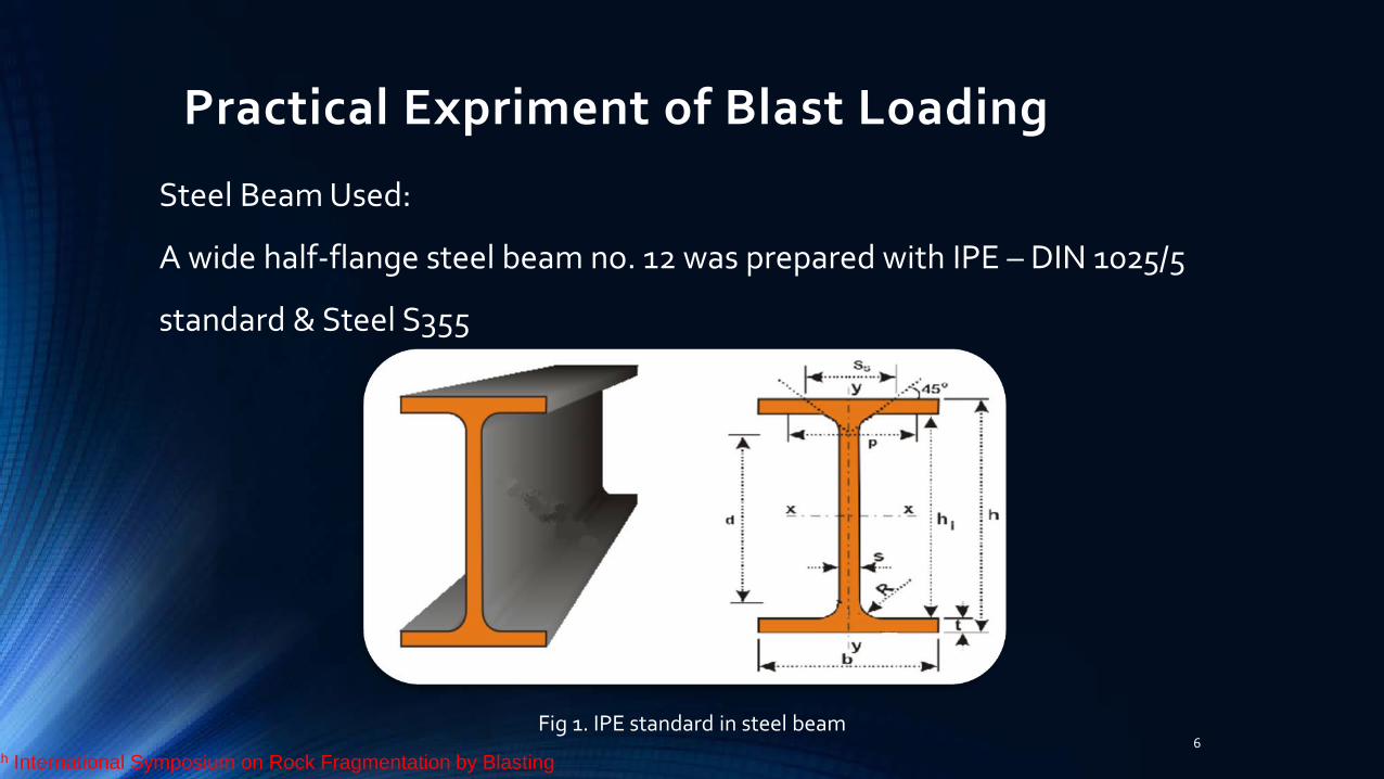
Steel Beam Used:
A wide half-flange steel beam no. 12 was prepared with IPE – DIN 1025/5
standard & Steel S355
Fig 1. IPE standard in steel beam th International Symposium on Rock Fragmentation by Blasting
Practical Expriment of Blast Loading
7
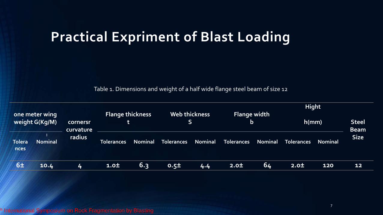
Table 1. Dimensions and weight of a half wide flange steel beam of size 12
Steel Beam Size
Hight
h(mm)
Flange width b
Web thickness
S
Flange thickness
t
cornersr curvature
radius
one meter wing weight G(Kg/M)
Nominal
Tolerances
Nominal
Tolerances
Nominal
Tolerances
Nominal
Tolerances
اNominal
Tolerances
12 120 2.0± 64 2.0± 4.4 0.5± 6.3 1.0± 4 10.4 6±
th International Symposium on Rock Fragmentation by Blasting
Practical Expriment of Blast Loading
8
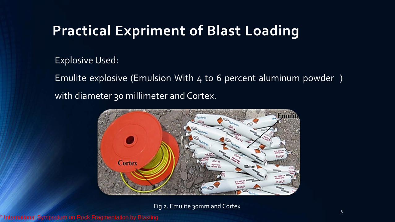
Explosive Used:
Emulite explosive (Emulsion With 4 to 6 percent aluminum powder )
with diameter 30 millimeter and Cortex.
Fig 2. Emulite 30mm and Cortex th International Symposium on Rock Fragmentation by Blasting
Practical Expriment of Blast Loading
9
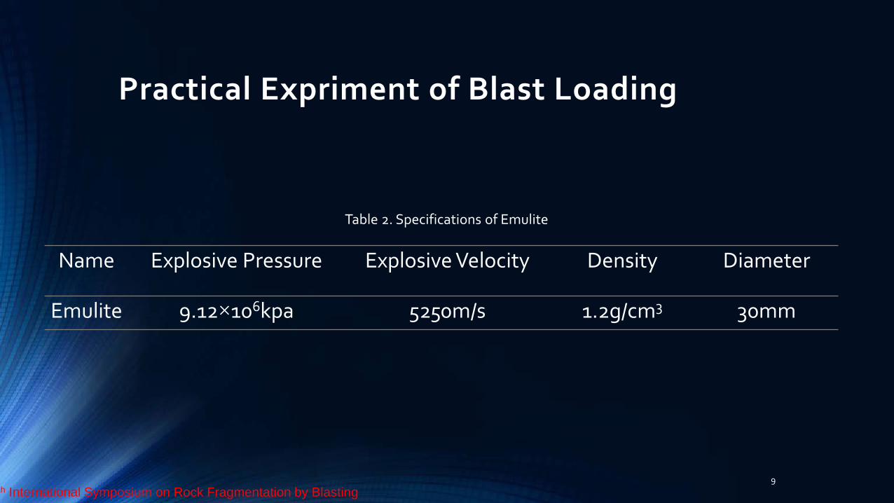
Table 2. Specifications of Emulite
Diameter Density Explosive Velocity Explosive Pressure Name
30mm 1.2g/cm3 5250m/s 9.12×10⁶kpa Emulite
th International Symposium on Rock Fragmentation by Blasting
Practical Expriment of Blast Loading
10
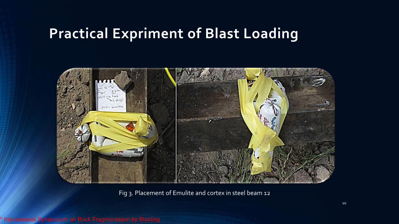
Fig 3. Placement of Emulite and cortex in steel beam 12
th International Symposium on Rock Fragmentation by Blasting
Practical Expriment of Blast Loading
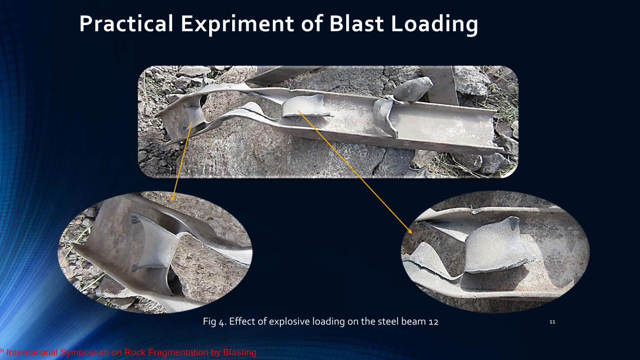
11 Fig 4. Effect of explosive loading on the steel beam 12
th International Symposium on Rock Fragmentation by Blasting
Effect of explosive loading on the steel beam 12
12
The resulting cut pattern in Emulite loaded site, a bend on beams'
flanges as well as a bend in the middle of beams indicate high
explosive power and pressure on contact surface. In order to examine
the resulting cut pattern, we repeated the experiment on five steel
beams no.12, 5 steel beams no.16 and five other steel beams no.18. The
same cut pattern was observed for all the beams
th International Symposium on Rock Fragmentation by Blasting
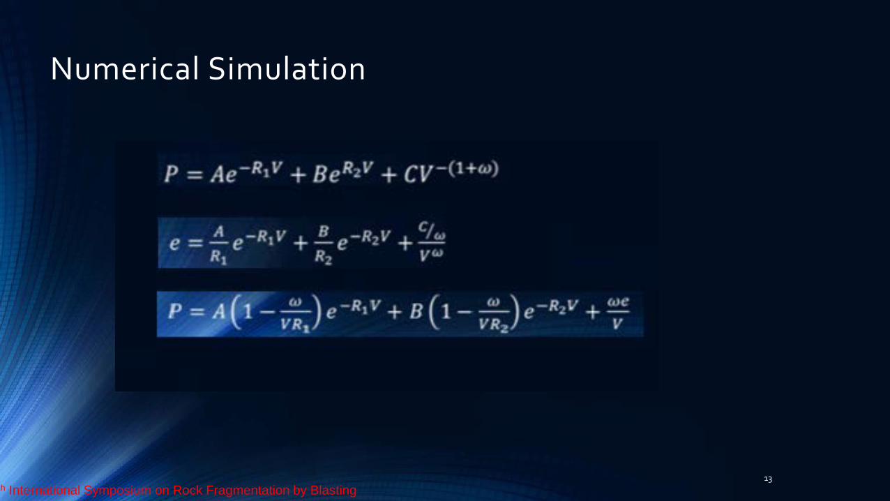
Numerical Simulation
13 th International Symposium on Rock Fragmentation by Blasting
Numerical Similation
14
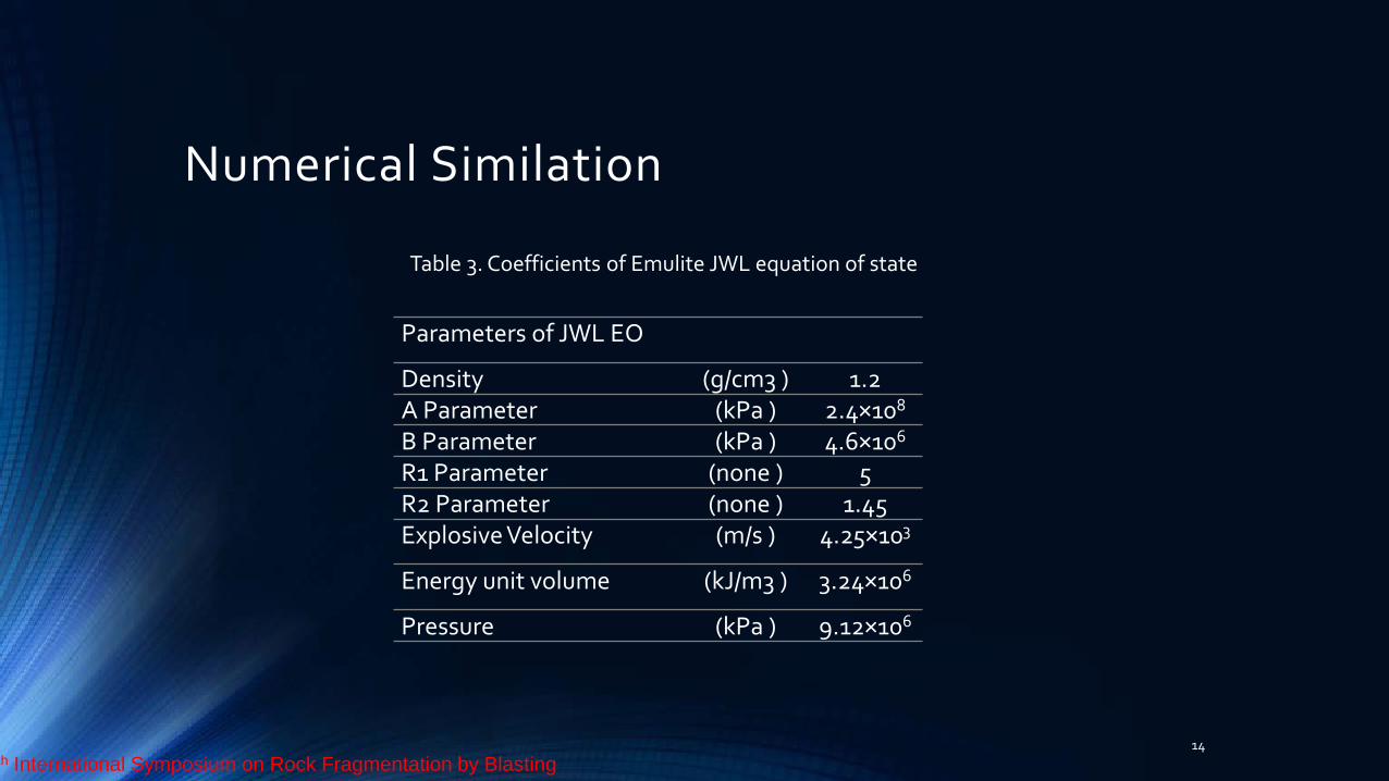
Table 3. Coefficients of Emulite JWL equation of state
Parameters of JWL EO
1.2 (g/cm3 ) Density 2.4×10⁸ (kPa ) A Parameter 4.6×10⁶ (kPa ) B Parameter
5 (none ) R1 Parameter 1.45 (none ) R2 Parameter
4.25×10³ (m/s ) Explosive Velocity
3.24×10⁶ (kJ/m3 ) Energy unit volume
9.12×10⁶ (kPa ) Pressure
th International Symposium on Rock Fragmentation by Blasting
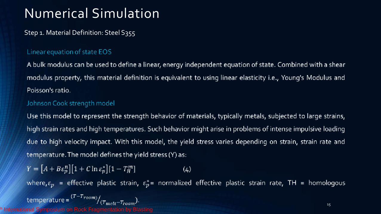
Numerical Simulation
15
Step 1. Material Definition: Steel S355
th International Symposium on Rock Fragmentation by Blasting
Numerical Simulation
16 th International Symposium on Rock Fragmentation by Blasting
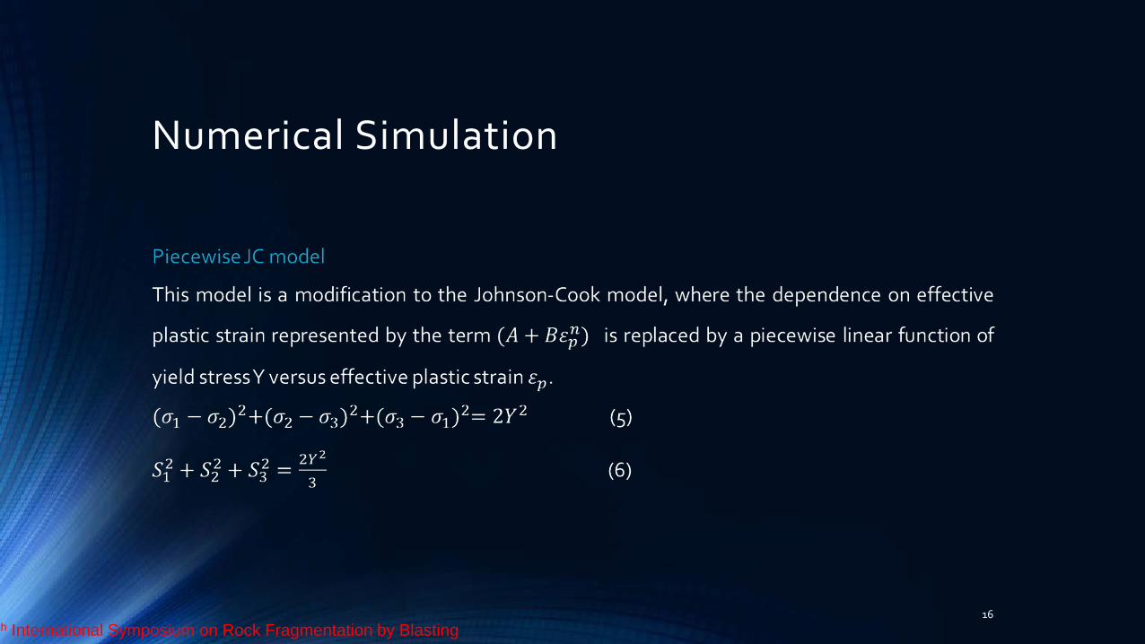
Numerical Simulation
17
Linear Equation of State 7.8 (g/cm3 ) Reference density 1.77×10⁸ (kPa ) Bulk Modulus 2.93 (K ) Reference Temperature Piecewise JC Strength 7.9×10⁷ (kPa ) Shear Modulus 3.55×10⁵ (kPa ) Yield Stress (zero plastic strain)
1.18×10⁵ (none ) Eff. Plastic Strain #1 0.22 (none ) Eff. Plastic Strain #2 4.8×10⁵ (kPa ) Yield Stress #1 6×10⁵ (kPa ) Yield Stress #2
Table 7. Coefficients of the equation of state of steel S355
th International Symposium on Rock Fragmentation by Blasting
Numerical Similation
18
Step 2. Geometric Model: Emulite
Fig 6. Useless model of emulite
th International Symposium on Rock Fragmentation by Blasting
Numerical Similation
19
Fig 7. Emulite model used in simulation experiments
th International Symposium on Rock Fragmentation by Blasting
Numerical Similation
20
Fig 8. Geometric models of steel beam 12
th International Symposium on Rock Fragmentation by Blasting
Numerical Simulation
21
Fig 9. Placement of emulite on steel beam size 12
th International Symposium on Rock Fragmentation by Blasting
Output of simulation experiment
22
Fig 10. Effect of explosive loading on steel beam 12 in the simulation tests at moment 3.5ms
th International Symposium on Rock Fragmentation by Blasting
Output of simulation experiment
23 Fig 11. Comparison of explosive loading on the beam size 12 in both experiment and simulation tests
Output of simulation experiment
24
Fig 12. Van mis stress distribution in steel beam size 12
351700KP
1243KP
th International Symposium on Rock Fragmentation by Blasting
Output of simulation experiment
25
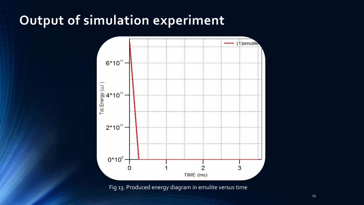
Fig 13. Produced energy diagram in emulite versus time
Output of simulation experiment
26
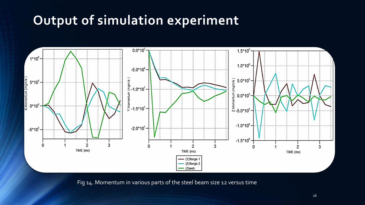
Fig 14. Momentum in various parts of the steel beam size 12 versus time
Conclusion
27
In the present article, the effect of Emulate explosive loading was examined on
steel beam no.12. A numerical simulation and an experiment were done with the
help of AUTODYN software. The experiment was conducted on 5 steel beams.
Some other experiments were done on steel beam no. 16 and 18 for closer
examinations, but they're not explained here.
th International Symposium on Rock Fragmentation by Blasting
Conclusion
28
The following results were obtained:
● A similar cut pattern and bend on steel beams in both the experiment and
simulation. The effect of explosive loading on steel beams included a deep cut on the
surface of beams' web and bends on flanges. The length of cuts on steel beam's web
was approximately 124 and 200 millimeter on X axis in simulation and in the
experiment respectively.
● Emulite time- energy diagram indicates high energy of this explosive substance at
the very first moments (6.7×10¹¹ uJ), suggesting high destructive power of high
explosive substances. th International Symposium on Rock Fragmentation by Blasting
Conclusion
29
● Color contours related to Von Mises Stress suggests strong stress imposed on
different parts of steel beams. Maximum stress at 0.66 ms is about 351700
kilopascal. This indicates high destructive power of high explosive substances.
● Time - momentum diagram shows the biggest momentum at early moments.
Therefore, we can conclude that there's a direct and one-way relationship
between the energy produced by emulite and the stress imposed on different
parts of steel beams and also between the momentum and stress imposed on
beams.
th International Symposium on Rock Fragmentation by Blasting
Conclusion
30
A comparison of patterns in the two experiments suggests a considerable
similarity between them. This similarity represents the precision of numerical
simulation and the reliability of AUTODYN. Of course, slight differences were
obvious in the two experiments including:
1) the percentage of coefficient errors related to the definition of substances
in simulation experiment such as errors in coefficients which are obtained
from state equation.
2) the differences between geometrical modeling of elements used in the
experiment and what is seen in the reality.
3) errors related to computer software analysis.
4) computer analysis power. th International Symposium on Rock Fragmentation by Blasting

Thanks for your attention
th International Symposium on Rock Fragmentation by Blasting