Embed Size (px)
Citation preview

I
I
MIL-B-8831B23 August 1982
SUPERSEDINGMIL-B-8831A I
2B January 1972
I
I
MILITARY SPECIFICATION
BOLT, 180 KSI Ftu and 108 KSI Fsu,PROTRUDING AND FLUSH READ ;GENERAL SPECIFICATION FOR
This specification is approved for use byAgencies of tbe Department of Defense.
1. SCOPE
450°F
all Departments and
1.1 *. This specification is for bolts used wheretemperatures are not greater than 450?F and ultimate tensile strength is180 SCSIFtu,(ultimate tensile stress) and 108 SCSIFsu.
2. APPLICABLE DOCUMENTS
2.1 Government documents.
2.1.1 Specifications and standards. Unless otherwisespecified, the following specifications and standards of the issue
listed in that issue of the Department of Defense Index of Specificationsand Standards (DoDISS) as specified in the solicitation, form a part ofthis specification to the extent specified herein.
sPECIFICATIONS
FEDEIUiL
QQ-P-416.
PPP-B-566
PPP-B-585
PPP-B-601
PPP-B-621
PPP-B-636
PPP-B-665
Plating, Cadmium (Electrodep$mited)
Boxes, Folding, Paperboard :
Boxes, Wood, Wirebound
Boxes, Wood, Cleated-Plywood
Box, Wood, Nailed and Lock-Corner
Box, Fiberboard
Boxes, Paperboard, .Metal Stayed ‘(IncludingStayMaterial)
Beneficial co~ents (recommendations, additions, deletions).and any
ipertinent data which may be of use in improving this docume t should beaddressed to: Commanding Officer, Naval Air Engineering”Cen er, ESSD,Lakehurst, NJ 08733, by using the self-addressed Standardiz~/ion DocumentImprovement Proposal (DD Form 1426) appearing at the end of’th,isdoctientor by.,letter.
FSC 5306
Downloaded from http://www.everyspec.com

MIL-B-8831B
SPECIFICATIONS (Continued)
FEDESAL (Continued)
PPP-B-676 Boxes, Set-Up, Paperboard
MILITA5Y
MIL-P-116 Pre8ervation, Methods of
MIL-B-121 Barrier Material, Greaseproofed, Waterproofed,Flexible
MIL-I-6868 Inspection Process, Magnetic Particle
MIL-H-6875 Heat Treatment “of Steels (Aircraft Practice)Proceaa for
MI.L-S-8879 Screw Threads, Controlled Radius Soot withIncreased Minor Diameter; General Specificationfor
MIL-N-8922 Nut, Self-locking, Steel, 220 KSI Ftu, 450°.F
MIL-N-8985 Nut, Self-locking, Steel, 180 KSI Ftu, 450°F
MIL-L-i0547 Liners, Case, Waterproof
(See Supplement 1 for applicable specification sheets and standards.)
STANDABDS
MILITA5Y
MIL-STD-105 %npling Procedures and Tables for Inspectionby Attributes
MIL-STD-129 Marking for Shipment and Storage
MIL-STD-1186 Cushioning, Anchoring, Bracing, Blocking andWaterproofing with Appropriate Test Methods
I MIL-STD-1312 Fasteners, Test Methods
I
(Copies of specifications, standards, handbooks, drawings and publicationsrequired by manufacturers in connection with apecific acquisition functionsshould be obtaimed from the contracting activity or as directed by thec0ntractin8 officer.)
2
Downloaded from http://www.everyspec.com

MIL-B-8831B
2.2 Other publications. The following documente form apart of this specification tn the extent specified herein. The issuesof the documents which are indicated M DoD adopted s~ll be the ISSU=11sted in the current DnDISS and the supplement thereto, if applicable.
A&R2CAN NATIONAL STANDARDS INSTITUTE (ANSI)
ANSI B46.1-1978 Surface Texture (Surface Rnughness, Wavinessand f,ay)
(Application fOr cOPiee shO~d be addressed tn the American StandardsInstitute, 1430 Brnadway, New York, NY 10018.)
NATIONAL AEROSPACE STANDARDS (WAS)
NAS 1348 Fasteners - Recommended Tensfie Streee Areaefoy External Threaded Alloy Steel.
(Application for copies shnu.ldbe addressed to National Standards Associating,5161 River Road, Washington, D.C. 20016.).
2.3 Order of precedence. In the event of a conflictbetween the text of thie specification and refereniea cited herein, thetext of this apecification shall take precedence.
3. REQUIREMENTS
3.1 Specification sheets and standards. The individualitem requirements shall be as specified herein and in accordance withthe applicable specification sheets and atandarda. In the event of anyconflict between the requirements of this specification and the specificationsheet, the latter shall govern.
3.2 Qualification. The bolt furnished under this specificationshall be a product which is qualified for 11sting on the applicable@xalified Producte List at the time set for ripeningof .bida (see 4.3 and6.3).
3.2.1 Retention nf qualification. To maintain status on aQualiflad Products List, certification shrillbe submitted at two yearintervals to indicate continued compliance with the requirements nf thisspecification (see 4.3.2).
3.3 Material. The material shall be as specified on
applicable specification sheet or standard. Unless otherwise specified,the choice nf material’sha21 be based on the abllity of the bnlt tocnnforp to the etrength requirements.
3
Downloaded from http://www.everyspec.com

MIL-B-883IB
3.4 Design and construction.
3.4.1 Dimensions. The dimensions of the bolt shall conformto the applicable specification sheets or military standard.
3.4.2 Threads.
3.4.2.1 Thread dimensions and focm. The thread dimensions,form and contour shall conform to MIL-S-8879 and shall be right handed.
1 3.4.2.2 Thread”rollin~. Threads shall be fully formed byany single rolling process subsequent to heat treatment.
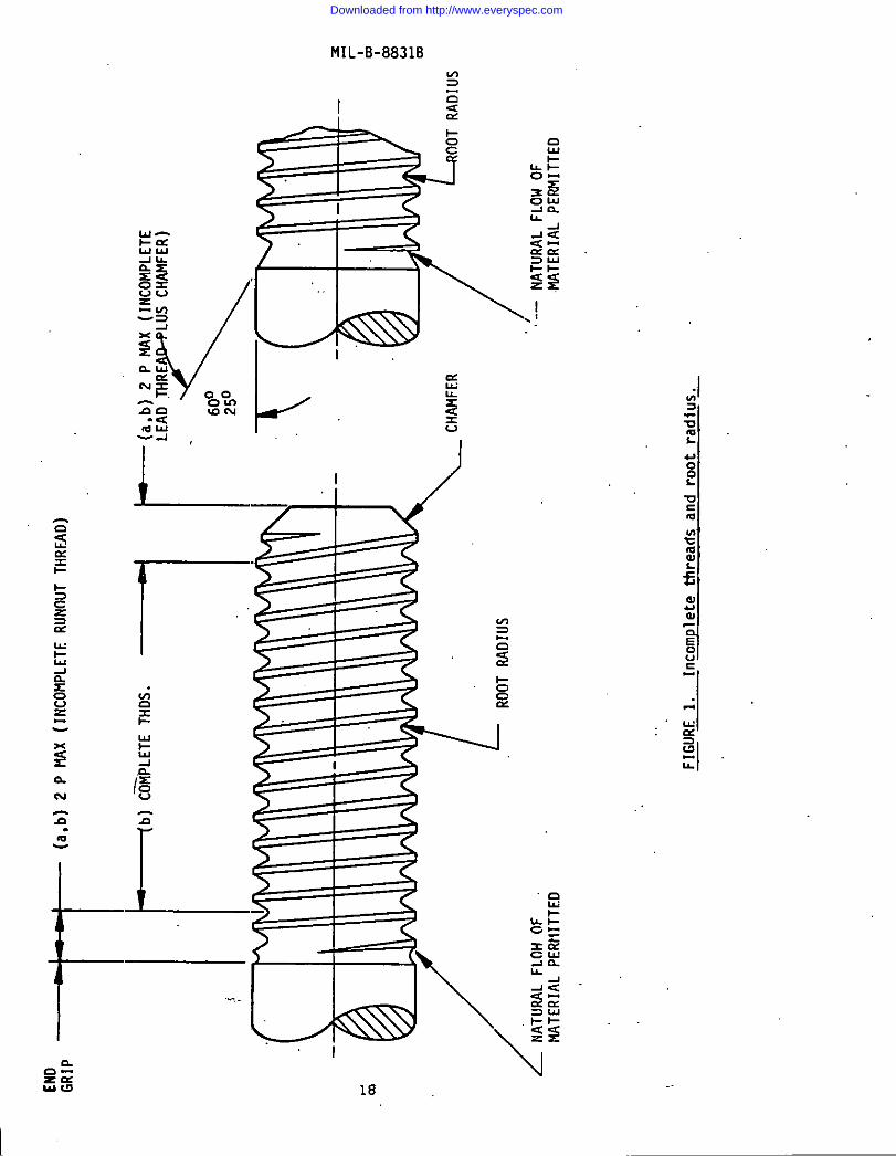
3.4.2.3 Incomplete threads: Thread xunout, consisting of not
more than’two Incomplete threads, shall”fair onto shank, therebyeliminating an abrupt change in cross sectional area as illustrated infigure 1. There shall be a thread runout of not less than one thread.
Bottom and sides of threads in runout may deviate from true thread form,but shall be smooth and devoid of tool marks. Incomplete threads shallconform to figure 1A (see 4.5.1.1.3).
3.4.2.4 Grain flow. The grain flow in the threads shall becentinuous and shall follow the thread contour with the meximum density
I at the bottom of the root radius as shown in figure 2.
1 3.4.3 Heads. The bolt heads shall be forged. Forged ormachined lightening holes for reduction of weight are acceptable forprotruding head bolts.
3.4.3.1 Wrenching element, The wrenching element shall bein accordance with the applicable specification sheets or standarda.
3.4.3.2 Bearing surface (protruding head). The bearingsurface of protruding bolt heads shall be at right angles to the shankwithin the limits shown in figure 3. The angular error of the undersideof the head must be uniform around the shank within ~ 10 minutes, as:measured from the bearing.surface of the head to a ,lengthequal to thediameter of the bolt.
3.4.3.3 Head stmcture and grain flow. A section of thehead, when examined aa specified in 4.5.3.6 shafi show no defects. Flowlines in the fillet area below the surface shall closely conform to thefillet contour as shown in figure 4. The metal removed from the bearingsurface shall be as little as practicable to obtain a clean, smoothsurface. For protruding head bolts only, the Intersection of the longitu-dinal axis of the bolt and the approximate transverse Axis of the flowlines shall .be not leaa than D17 inches from the bearing surface of thebolt where “D” is the nominal diameter of the bolt (see 4.5.3.6).
I
,4
1 3.4..4 Fine t (bead-to-shank). The head-to-shank filletradius shall meet the fatigue strength requirements specified in 3.9.4.The fillet ehall be finished to the radius specified on the applicable
Downloaded from http://www.everyspec.com

I
M2L-B-8831B
I
I
>,
I
standards. The working on the ffilet radius shall be accomplishedsubsequent to the heat treatment of the bolt. The fillet shall show noevidence of seam or inclusions when tested as specified in 4.5.2.2.2.
3.4.4.1 Distortion of fillet area. Cold working of head-to- !shank fillet may cause distortion of fillet area. Distortion shall beno”tgreater than height (A) and depth (B) of O.002-inch and the distortedarea shall not extend beyond (C), as illustrated on figure 8.
3.5 Surface texture. The surface texture of the bolt,afcer plating, shall.be not greater than the values shown in table I.The surface texture shall be meaaured in accordance with ANSI B46.1 (see4.5.1.1.1).
‘D&S1. Roughness height rating (R.).
Ar= Maxhum Microinchee (p)
‘Shankand undersize of haad 32Eead-to-shank fillet 32Sides of thread and root araa 32Other surfaces. 125
3.6 Straightness. The straightness of the bolt shankshall be within the valuas specified in table II (see 4.5.1.1.1).
TABLE II. Straightness of shank.
De&atIon of bolt shankBolt Size from plate (Inch per Inch of
bolt length) (maximum)
5/16 and under 0.00303/8 and 7116 0.002,5112 and larger 0.0020
3.7 Heat treatment. Bolts shall be heat treated inaccordance with MIL-H-6875 to develop the mechanical propertiaa spacifiadherein. All bolts shall be retapered, subsequent to griiidingandbefore thread rolling and fillet vorklng at a temperature not graaterthan the original tempering temperature to a maximuui temperature of5130F.
3.8 Cadmium platin~ All surfaces of alloy steal shallbe cadmium plated in accordance with QQ-P-416, type II, class 2.
3.9 Mechanical properties.’
3.9.1, Ultimate tensile load. The finished bolts shalldevelop the ultimata tensile load listed in table III (see 4.5.3.2.1).
.-
Downloaded from http://www.everyspec.com

II
MIL-B-8831B
Ultlmate Tensile Double Shear Area AtNominal Lead (pounds Strength (pounds Basic ShankSize minimum) Al minimum) ~1 D2A (As) in2 ~J
#10-32 3.910 6,100114-28
.0284“6,980 10,600 .0491
5/16-24 11,100 16,600318-24
,076717,100 23,900 .1104
7/16-20 23,200 32,500 .15031/2-20 30,900 42,400 .1963
9/16-18 39,200 S3,700 .24855/8-18 49,000 66,300314-16
.306B71,100 95,400
7/8-14.4418
97,100 129,900 .60131- -12 126,000 169,600 .78541-1/8-12 162,000 214,700 .99401-1/4-12 202,000 265,1001-3/8-12
1.2270247,000 320,700 1.4850
1-1/2-12 296,000 381,700 1.7670
TABLE III. Mechanical uror.erties.
,.
Al The stress ar6.asused for the calculation of the ultimate tensileload values are based on the basic pitch diameter of the external
~thread as specifled in NAS 1348.
I ~1 The listed shear values are based on a minimum 2X single shearstrength of 108 KSI and the stress area at nominal shank diameter.
I
3.9.2 Double shear strength. The bolts shall meet thedouble shear values listed in table III (see 4.5.3.2.2).
3.9.3 Bardnese. Bolts shall have a Rockwell hardness ofC39 to C43 (see 4.5.~
3.9.4 Fatigue strength. Bolts shall be capable of withstandingnot legs than 65,000 fatigue cycles when loaded in accordance with tableIV (see 4.5.3.2.3). Bolts need not be tested in excess of 130,000 cyclesif failure has not occurred before that the.
3.9.5 Stress durability. The bolts shall satisfactorilypass the stress durability test of 6.5.3.3.
II
3.10 Metallurgical properties,
3.10.1 Carburization and nitrogenization. The bolts shallshow no decarburization. carburization, recarburization or increase innitrogenization on the bearing eurface of the head-to-shank fillet,shank, or threads (see 4.5.3.4).
1 3.10.2 Work effect. The bolt threads and h&d-to-shankfillet shall show evidence of working when tested as specified in 4.5.3.5.
I\
I 6
Downloaded from http://www.everyspec.com

. MIL-B-8831B
TA8LB IV. Fatigue loadinK.
N&inal Bolt Low-Tension High-’fensionDiameter Load (pounds) Load (poynds)(inchee) 22 percent ~1 22 percent AI
10-32 180 1,8001/4-28 321
5116-24
3,210510 5,100
318-24 786 7,B607/16-20 1,065 .10,650
1/2-20 1,420 14,2009/16-18 1,800 18,000
518-18 2,2503/4-16
22,5oo3,270 32,700
718-14 4,460 44,600
1 -12 5,790 57,900
1-1/8-12 : 7,450
1-1/4-12
74,5009,290
1-318-12
92,90011,340 113,400
1-1/2-12 13,600 136,000
~1 Ei8h-tenSiOU load is based on .46 x Ftu of.table III.
y law-tension load ie 10 percent of high-tension load.
3.10.3 Discontinuities. All bolts ehcll be examined by ““
LW31MIC partiCle inspection as specified in 4.5.2.2.2. Eeade of boltsehall not be marked for identification of magnetic inspection. Anybolts having discontinuities equal to or exceeding the limitationsepecified herein shall be rejected. Care must be exercised to avoidconfueing cracks. ae described herein (see 6.4.1), with otherdiscontinuities.
3.10.3.1 Creeks. Bolts shall be free from cracks in anydirection or location.
3.10.3.2 Laps and seams. Bolts may possess laps (see 6.4.2)
and seams (eee 6.4.3), except in 10catiOne specified in 3.10.3.5. Thedepthe shall be not greater than the amounts epecified.in table V.
Tl@LS V. Discontinuity depths. ~1
Bolt Size #lo, 1/4 5/16 3/8 7116 1/2 thru 1-1/2 Incl
“SeamDepth (inch) 0.005 0.005 “0.006 0.007 0.008(!ardlmm)
y Depth of discontinuity shall be measured normal to the surface at thepoint of greateet penetration.
7
Downloaded from http://www.everyspec.com

I
II
MIL-B-8831B
3.10.3.3 Inclusions. The bolt shall show no evidence ofsurface or subsurface inclusions at the.thread root or head-to-shankfillet (see 4.5.2.2.2). SMCll inclusions on other parts of the bolt arenot indicative of unsatisfactory quality.
..3.10.3.4 Head and shank discontinuities (seams, inclusions,
or folds). Seams, inclusions, or folds along the top or sides of thebolt head shall be not greater than twice the depth limits shown intable V. The seams on the bearing surface shall be not greater than thelimits shown in table V. There shall be no discontinuities on the head-to-shcnk fillet.
3.10.3.5 Thread discontinuities (laps, seams, and surfaceirregularities). Threads shell have no multiple or single laps at theroot or on the aides (see figure 5). Laps are permissible at the crestwhich are not greater than 25 percent of basic thread depth. Laps arapermissible above the pitch diameter (see figure 6). .Slightdeviationfrom the thread contour is permissible at the crest of the thread aB
shown in figure 6. 2he incomplete thread at each end of the thread mayalso deviate slightly from contour.
3.10.4 Grinding burns. The bolt shall show no evidence ofgrinding burns (see 4.5.3.8).
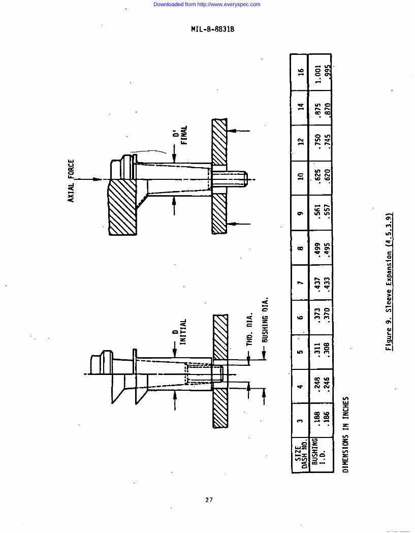
3.11 Sleeve expanaion. When the sleeve is pushed to thepin head, the expanded bolt sleeve diameter shall be as specified on the
applicable specification sheet (see 4.5.3.9).
3.12 Identification of product. Sach bolt shall bemarked on top of the head or side of the flange. The manufacturer’sidentification shall be mcrked on the top or side of the head or on thebase of the lightening hole. Mcrkings mcy be raised or indented notmore than O.10-inch, except that only raised mcrkings shall be used onthe lightening hole. Markinga may be forged or stamped.
4. QUALITY ASS7 PROVISIONS
4.1 ~Responaibility for Inspection. Unless bthemisespecified in the contract or purchcae order, the contractor laresponsible.for the performance of all Inspection requirements asspecified herein. Sxcapt as otherwise specified in the contract or .-purchase order, the contractor may uae his own or any other facilitiessuitable for the performance of the inspection requirements specifiedherein, unleaa disapproved by the Government. The Government reaerveethe right to perfono any of the inspections set forth in thespecification where such inapectiona are deemed necessary,to assure
~PPlies and ae=icea conform to prescribed requirements.
8
Downloaded from http://www.everyspec.com

MIL-B-8831B
4.2 Classification of inspections. The inspectionrequirements specified herein are classified as follows:
a. QualifIcation inspection (see 4.3). I
b. Quality confomsnce inspection (see 4.4).
.4.3 Qualification inspections. The qualification inspectionsshall consist of the tests listed in table VI as specified under 4.5.
4.3.1 Sampling size. Tha qualification test samples shall,consistof 15 bolts for each diamster for which qualification is desired.Samples up to and including l/2-inch diameter shall have a grip leagchof 1-3/8 inches; samples from 9/16-inch diameter up to and including 1-l/2-inch diameter shall have a minimum grip length of 4 inchee. 1Paddition, the manufacturer shall eupply 15 nuts cnnfomning to MIL-N-8922and M2L-N-8985 and tested in accordance with MIL-STD-1312, Teet 11.Samples shall be identified and forwarded tn the activity responsible forqualification, deeigmated in the letter nf authorization from thatactivity (see 6.3).
TABLE VI. Qualification inspections.
Inspections Number of Requ.&&.nt InspectionSamples Paragraph Paragraph 1
ultimate Tensile Load 3Double Shear Strength 3Fatigue Strength 3stress Durability 3Carburization and Nitrogenization 1Grinding Burns 3Sleeve Sxpaneion 3
3.9.13.9.23.9.43.9.53.10.13.10.43.11
4.5.3.2.14.S.3.2.24.5.3.2.34.5.3.34.5.3.44.5.3.84.5.3.9
4.3.2 Retention of qualificatioa. To comply with therequirements sueclfied in 3.2.1, the manufacturer shall forward qualificationce~tification ~o the Commander, Naval Air Development Center, Code 6013,Warminster, PA 18974. This certification, signed by a responsibleofficial of management, shall atteet that the manufacturer has thecapability to produce bolts under conditions equal to those exieting atthe time of the originnl approved lieting.
4.4 Quality conformance inspecting. The quality confo~nceinspections shall coneist of all the teete specified in table VII.
f,>,.
I
9
I
Downloaded from http://www.everyspec.com

.4!
MIL-E8831B
TABLS VII. Quality conformance inspections.
Number Requirement Inf3pecti0nI.napection of Samples Paragraph Paragraph
straightness and 3 3.5 4.5.1.1.1Surface Texture 3.6
cracks and 3’ 3.10.3 4.5.2.2.2Discontinuities 3.10.3.1
Magnetic Particle 4.5.2.2.2..1In8pectL0n
Carburization aud 3.10.1 .4.5.3.4Nitrogenization
Work Effect 3.10.2 4.5.3.5
Head Structure 1 3..4.,3.3 4.5.3.6and Grain Plow
Tranverse Hardness 3 4.5.3.1
Grinding Burns 3.10.4 4.5.3.8
4;4.1 Sampling.
4.4.1.1 Inspection lot. An inspection lot shall consist ofbolte, fr~ a single production 10t. nf one part number wMch indicatesone size, one grip ,leagth,and whether.the h=ds are drilled Or ~drilled.
4.4.1:2 Prnductinn lot. A production lnt shall consist nffIniehed bolts, which have the same part number; fabricated frnm asingle mill heat by the same procese, heat treated in the same reamer,and produced aa one continuous run or nrder.
4.4.1.3 Randnm sample. A random ample is a semple dravn “insuch a manner that each unit (bnlt) in the inspect~on lot has the samechance of being the first unit in the random sample; after the first,ynlt in the sample is:drawn, each of the remaining units in the inspectionlot haa the same chance nf”being the second unit in the sample, et,:..
4.4.1.4 Inspection recorde. Copies of “allrecnrds ande.xa+ations a@21 be certified and ahal..lbe supplied for each productionlot or portion thereof. These records shall identify the manufacturersof the bolts and provide tha address of the plent vhere the bolts weremanufactured. The records shall be available tn the purchaser and shallbe signed by an authorized representative of the manufacturer.
10
Downloaded from http://www.everyspec.com

IMIL-B-8831B
4.5 Test methods.
4.5.1 Visual and dimensional inspection.
4;5.1.1 , ?.amplin~. A random sample shall be selected fromeach inspection lot in accordance with MIL-STD-105, acceptable qualitylevel (AQL) of 1.0 percent defective for Najor defects, 2.5 percentdefective for Minor A defects and 4.0 percent defective for Minor Bdefects.“
4.5.1.1.1 Straightness and surface texture. Straightnessshall be measured by the use of a dial-type indicator gage. Surfacetexture of threads shall be determined by a visual comparator method.
4.5.1.1.2 Classification of defects. The classification ofdefects.fOr bolts shall be as specified in table VIII.
Category
Critical,Major:
101102103104105106107108109110111112113.
Uinor A:201202203204205206207
Mimr B:301302
TABLS VIII. Classification of defects.
Defect
None defined
l%read size and formShank diameter (B)Imperfect threadsGrip lengthRadius under head (R)Drilled holee in head missing (when required)Squareness between head and shank (bearing surface)Straightness of shankSurface textureBurrs and tool marksSurfac.&finish, platingIdentificationInatallation
Overall length (L)Head diamater (A)Head height (H)Socket dimensions (E and J)Concentricity of head and shank (X)Concentricity of shank and thread pitch diameter (Z)Drilled hole diameters and location (H and M)
Chamfer on thraad endFlange height (Q)
NOTE: Lettere in parentheses correspond to dimensions specified inMS21134 and MB21250.
Downloaded from http://www.everyspec.com

IMIL-B-8831B
4.5.1.1.3 Incomplete threads. Incomplete threads ehall beinspected for compliance to figure 1A.
4.5.1.1.4 Dimensions. Dfmensiom shall be checked by means of
applicable gages or optical comparators.
.4.5.2 Nondestructive teste.
4.5.2.1 Sampling“plan. Statistical sampling shall be inaccordance with MIL-STD-105, except for magnetic particle inspectionwhich shall be 100 percent inspected. The AQL shall be 2.5 percent
defective and the inspection level shall be S-4. The sample units maybe selected from those that have been subjected to and passed the visualand dimensional inspection.
4.5.2.2 Method.
4.5.2.2.1 Sardne.sa. Bolts shall be inspected for SOckwe.11hardness in accordance with KIL-SID-1312, Teet 6.
4.5.2.2.2 Cracke and discontinuities. The presence of crackeand discontinuitiee in bolts such as laps, seam, and inclusions shallbe determined by magnetic particle inspection. Particle indications ofthemselves shall not be cause for rejection. If, in the opinion of theinspector, the indications are cause for rejection, the bolts shall beexamined by microexamination to determine if the discontinuities arewithin the limits specified herein.
4.5.2.2.2.1 Magnetic particle inspection. Magnetic particle
inspection still be performed in accordance with MIL-I-6868. The boltsshall be magnetically inspected by both the longitudinal and circularmethods.
4.5.3 Destructive tests.
4.5.3.1 Sampling Plan. The sampling procedure shall be inaccordance vith MIL-STD-105. Normal inspection shall be used at thestart of each production lot. The AQL shall be 1.0 percent defective :and the inspection level shall be s-2. The sample units may be selectedfrom those that have been subjected to and passed the nondestructivetests with additional units selected at random from the Inspection lotas necessary.
4.5.3.2 Strength tests. Acceptance of bolts shall be basedon the results of actual tensile and shear tests (4.5.3.2.1 and 4.5.3.2.2).In the event the bolts to be tested in shear have a grip of less thantwo times the shank diameter, the tensile test shall determine accept.sbility.
4.5.3.2.1 Tensile strength. The bolts shall be tested intension berwea the head of the bolt and a threaded member in accordancewith MIL-STD-1312, Test 8. In the event the bolt is too short to conductthe tensile test, acceptabilityy shall be based”on results of tbe hardnesstest (4.5.2.2.1).
12
Downloaded from http://www.everyspec.com

MIL-B-8831B
4.5.3.2.2 Shear etrength. The doubleshall be performed on the unthreaded portion ofwith MIL-STO-1312, Test 13.
. .
shear strength testthe bolt, in accordance
4.5.3.2.3 Fetigue strength. The bolts with expandable sleevespushed to the bolt head shall be used for thie test. Cracks in thesleeve will not constitute failure of the bolt. Parts having a griplength less than two times their diameter need not be fatigue tested,and acceptance for these shall be on the baais of their tensile strength.The fatigue loading applied to bnlts shall be tension-tension. Thefatigue teat shall be conducted at room temperature. The fatigue loading
applied tO the respective bOlts s~ll conform to table IV. The methodof testing and fixture requirements shall be in accordance with MIL-STD-1312, Teat 11.
‘4.5.3.3 Stress durability. The stress durability test shallbe conducted in accordance with MIL-STO-1312, Teat 5. The bolt shall bemaintained for 23 hours without failure.
4.5.3.4 Carburization and nitrogenization. Carburization,decarburization, recarburization, or nitrogenization nn the bearingsurface nf the head, head-tn-shank fillet, ahsnk and threads shall bedetermined by microexamination. Specimens shall be taken as shovn infigure 7. The specimens shall be etched in 5 percent nital and examinedOptically at 100X magnification. In caae of disagreement over carburization,decarburization, or nitrogenization, microhardness testing of the shankshall be used as a referee method, Sxcept aa noted herein, testing shallbe in accordance with HIL-S’iTk1312,Test 6. The indenter test load aball.be 200 grams. Three (3) readings shall be taken at “the core (a minimumdistance of 0.125 inch from the surface or at m.id;radiusWhichever laless). The average of these readings shall represent the core hardnea.s.Starting at a point 0.002 from the surface and tranaversing toward thecore, staggered reading shall be taken every 0.001 inch until the corehcrdness 18 reached. A microhardness reading within 0.003 of the surfacethat la higt@5 than the core reading by more than 10.points Snoop shallbe evidence of carburization. A microhardness reading within 0.003 ofthe surface lees than the core reading by 25 points knoop shall beevidence of decarburization. Any relative ac.ftsubsurface layerindicated by the microhardness suryey, ehall be evidence ofrecarburizatinn. This does not apply to the threads‘or fillet area.
4.5.3.5 lJorkeffect. The cold work of the bolt threadsshall be determined by microexaminatinn as specified in 4.5.3.6. Workeffect on the head-to-shank fillet shall be determined by visual examination.
4.5.3.6 Head structure and grain flow. Head structure andgrain flow shall be determined by macroexamination at a magnification of10 diameters. Specimens shall be taken from the finished bolt as shovnon figure 7. The bolts shall be etched in an aquegus solution containing50 percent (by volume) of hydrochloric acid at 160 to 180?F for sufficienttime to reveal the microstructure properly. /
13
Downloaded from http://www.everyspec.com

MIL-B-8831B
4.5.3.7 Tranverse hardness. The acceptance of bolts havinggrip lengths less than twice the nominal size shall be based on thetranverse hardness test taken on a circular cross section halfway betweenthe head surface and the thread. The Rockwell hardness range for acceptanceshall be C39 to c43. Readings shall be taken at distances of 1/8 inchfrom the surface, at one-half the radius, where practicable, and at thecore.
4.5.3.8
~
Indications of grinding burne(untemperedmartensite are white streaks appearing on the surface ofthe test sample after the following treatment:
a.
b.
c.
d.
e.
f.
g.
h.
Remove all foreign matter from the bolt suchgrease, dirt, pl=ting, or oxide fiber,
as
Rinse the bolt in cold water. If water brea~occur, bolts shall be recleaned.
Immerse and agitate the bolt in a 4 percentsolution of nitric acid for approximately 30seconds.
Rinse iu cold water and dry bolt.
Immerse the bolt in 2 percent solution ofhydrochloric acid in acetone for 30 seconds.
Rinse iu cold water.
Rinse the bolt in 5 percent sodium bicarbonatesolution.
Rinsethe bolt in hot water and dry.
4.5.3.9 Sleeve expansion. The sleeve shall be expanded bythe method shown in figure 9. Faflure to meet the dimensions as specifiedon the applicable specification sheet shall constitute failure.
4.5.4 Resubmitted inspection lots. The paragraph titled“Resubmitted lots” of MIL-STO-1O5.shall apply, except that a resubmittedinspection lot shall be inspected by the contractor, using tightenedinspection. Before an inspection lot is resubmitted, full particularsconcerning the cause of previous rejection and the action taken tocorrect the defects found in the inspection lot shall be furnished bythe contractor to the Government inspector.
4.6 Inspection of packagin~. The sampling and inspectionof the prkservation. packing, and container marking shall be in accordancewith Section 5..
14
Downloaded from http://www.everyspec.com

MIL-B-8831B
“5. PACSAGING
5.1 Packaging. ‘“
5.1.1 Preservation. Unless otherwise specified, each boltshall have the shank and threads protected by means of a sleeve extendingover the full length of the shank and thread. The sleeve shall bemanufactured from cardboard, asphalt-impregnated chip board, Plasticsleeve covering, or a spiral wrap of kraft paper over chip board, andshall be lined with material conforming to MIL-B-12L.
5.1.2 Intermediate packaging. Cnly identical items shallbe included in an intermediate package. Bolts, preserved and pacbgedas .specified in 5.1.1, shall be packaged in containers conforming toPPP-B-566, PPP-B-636. PPP-B-665, or PPP-B-676. Un3ess otherwise specifiedby the procur+ng activity, the quantity of unit packages shall be asspecified in table IX (see 6.2).
TABLB IX. Allowable quantities per package.
maximum quantitySize ‘Length per carton
#10 to 5116 Up to 1-1/2 inch 100#10 to 5/16 1-1/2 in. to 3 in. 50318 and 9/16 up to 3 ill;#10 to 9/16
50Over 3 in. 25
Over 9/16 All lengths 25
5.2 ~. Packing shall be level A or commercialpackaging, as specified (see 6.2).
s.2.1. Level A. Bolts, preserved and packaged as specifiedin 5.1 shall be packed in overseas containers conforming to PPP-B-585,PPP-B-621, or PPP-B-601. Plywood containers shall be surface treated inaccordance vith the apecification. As far as.practicable, exteriorshipping container shall be of uniform shape and size, be of minimumcube and tare consistent with the protection required, “and containidentical quantities. The gross weight of each pack shall be limited toapproximately 200 pounds. Containers shall be closed and strapped inaccordance with the applicable container specification ox appendfithereto. Ccmtalners shall be provided with a case liner conforming toMIL-L-10547 and shall be sealed in accordance with the appendix thereto..The case liner will not be required when the intermediate containerconforms to PPP-B-636, class weather-resistant, closed and taped inaccordance with the appendix.
5.2.2 Camnercial packaging. Packages which require overpackingfor acceptance by the carrier shall be packed in exterior-type shippingcontainers in a manner that vI1l insure safe transportation at thelowest rate to the point of delivery. Containers Bhall conform to theUniform Freight Classification Rules or regulations of other commoncarriers as applicable to the mode of transportation.
15
Downloaded from http://www.everyspec.com

5.3and bolting, asexcept that for
MIL-B-8831B
Physical protection. Cushioning, blocking, bracing,required. shall be in accordance with MIL-STD-1186..domestic ehimnents. wateruroofin~ requirements for-..
cushioning materials and containers shall be waived. Drop tests ofMIL-STD-1186 shall be waivdd when packaging and packing of the it= isfor immediate use or when drop teste of MIL-P-116 are applicable.
5.4 Marking of shipments. In addition to any specialrequirements of the contract; shipments shall be marked in accordancewith MIL-STD-129.
6. NOTES
6.1 Intended use. Bolts covered by this specificationare intended for use in applications which require a bolt with 180,000PSI tensile strength and 108 KSI shear strength.
6.2 Ordering data.
6.2.1 Acquisition requirement. Acquisition docmnenteshould specify the following:
,a. Title, number, and date “of this specification.
b. Part number of”the bolt desired.
I c. Quantity (see table IX).
d. Applicable levels of packing (see 5.2).
6.3 Qualification. With reepect to products requiringqualification, awards will be made only for products which are at thetime set for opening of bids, qualified for inclusion in the applicablequalified Products List whether or not such pr6ducts have actually beenso listed by that date. The attention of the contractors 1s called tothese requirement, and manufacturers are urged to arrange to have tbeproducts that they propose to offer to the Federal Government tested for.qualification in order that they may be eligible to be awarded contractsor purchase orders for the products covered by this specification. Theactivity responsible for the Qualified Products Li8t is the Naval AirSystems Command, Navy Department; Washington, D.C. 20360; however,information pertaining to qualification of products may be obtained fromthe Naval Air Development Center (NADC), Warminster, Pennsylvania 18974Attention (tide 6061).
6.4 Definitions.
6,.4.1 Crack. A crack is defined as a clean crystallinebreak passing through the grain or grain boundary without the.inclusionof foreign elemente.
II
16
Downloaded from http://www.everyspec.com

MIL-B-8831B
6.4.2 ~. A lap is a surface defect appearing as a s-mcaused by folding over hot metal fins.or sharp corners and then rollingor forging them into the surface, but not welding them.
6..4.3 Seam. A eeam ie an unwelded fold or‘Iap+ich
aPP~rs as an OPenfng in the raw material as received from the Source. :
6.5 Chn?.es frOm Previous issue. Asteri.skaare not usedin this revision to identify changes vith respect to the previous Ise”edue to the extensiveness of the changes.
Custodtins: Preparing activity:Navy-AS Navy - ASAir Force - 11 Project No. 5306-0658Army - AV
17
Downloaded from http://www.everyspec.com
—-–
“T(a
,b)
2P
MAX
(INCO
MPL
ETE
RU
NO
UT
THR
FAO
)
rb)C~
MPL
ETE
THD
S.
~
. m
.
/N
ATU
RA
LFL
OH
OF
MAT
ERIA
LPE
RMIT
TED
I
RO
OT
RA
DIU
S
——
—(a
,b)
2p
wfx
(INCO
MPL
ETE
LEA
D~R
E~LU
SC
HA
MFE
R)
60°
25°
\
/ ..—N
ATU
RA
LFL
OW
OF
.+IA
TERI
ALPE
RMIT
TEO
.In
com
plet
eth
read
san
dro
otra
dius
&FI
GU
RE
1
Downloaded from http://www.everyspec.com

—–—
——
—
/R
UN
OU
TTH
REA
DS
+MA
x.2P
-A__
___
------
-SH
AN
K‘“
~i
---4,
+4,,
-J-- G .,
FIG
UR
E1A
.De
term
inat
ion
ofin
com
plet
eth
read
s.
Downloaded from http://www.everyspec.com

\,
FIG
UR
E2
Gra
fn
flow
inco
mpl
ete
thre
ads”
.’”—
.-.-
Downloaded from http://www.everyspec.com

NJ
W. *
v
-H+
.D
7
UN
IFO
RM
WIT
HIN
%
10M
INUT
ESTI
R
T—
—0
A
H
FIG
UR
E3.
.He
adan
qula
rlty
Downloaded from http://www.everyspec.com

w N
FLU
SHH
EAD
DM
IN.
7
MA
CH
INED
LIG
HTE
NIN
GH
OLE
ItlPA
CTED
LIG
HTE
NIN
GH
OLE
WIT
HO
UT
LIG
HTE
NIN
GH
OLE
PRO
TRU
DIN
GH
EAD
.
Figu
re4.
Forg
edHe
adSt
ruct
ure
and
Gra
inFl
ow.
Downloaded from http://www.everyspec.com

LAPS
AN
DSE
AMS
NO
TPE
RMIS
SIBL
E
N LJ
//
NO
NPR
ESSU
RE
FLA
NK
MAJ
OR
PITC
H
MIN
OR
DIAM
ETER
OIA
MET
ER
OIA
MET
ER
Figu
re5.
Non
Perin
issi
ble
Laps
,Se
ams
and
Surfa
ceIrr
egul
ariti
es.
Downloaded from http://www.everyspec.com

-..
SUR
FAC
EIR
REG
ULA
RIT
IES
NO
NPR
ESSU
RE
FLA
NK
S
MAJ
OR
PITC
H
MIN
OR
DIA.
DIA.
DIA.
Figu
re6.
Pers
niss
ible
Laps
,Se
ams
and
Surfa
ceIrr
egul
ariti
es.
-.
Downloaded from http://www.everyspec.com

7r)/
2H
IN
{
-D
(NO
H.
”DIA
.)
7s.
D/2
MIN
1
I~
——
——
—
—.,
—.
?
1—
——
——
—
CU
TH
ERE
FOR
SPEC
IMEN
S,,
MIC
RO
EXA
MIN
EOO
RM
AC
RO
EXAM
INED
Figu
re7.
Met
alIu
rgic
afSp
ecim
en.
Downloaded from http://www.everyspec.com

D
/“ \,\
+-f >
c
r
+L!
c
--4c
.
~km
lINAL
UN
DER
5/16
7/16
’314
SIZE
AN
D31
8TH
RO
UG
H51
8TH
RO
UG
H1
OVE
Ri
0.06
20.
094
0.12
50.
156
0.18
8
cM
AxR
EOU
CEO
FLU
SHH
EAD
TYPE
ON
LY
0.03
1:0
.047
I0.
062
I.0
780.
094
DIM
ENSI
ON
SIN
INC
HES
Figu
re8.
Perm
issi
ble
Fille
tDi
stor
tion
(3.3
.4.1
).
Downloaded from http://www.everyspec.com
AXIA
LFO
RC
E
I i #
~B
USH
ING
DIA.
SIZE
OA
SHN
O.
34
5,6
.?
89
1012
1416
BU
SHIN
GI.
D.
.Me
.248
.311
,373
.437
.499
,561
.625
.750
.875
1.0
01
.186
.246
.308
.370
.433
.495
.557
.620
.745
,870
995
O1M
ENS1
ONS
ININ
CH
ES
Figu
re9.
Slee
veEx
pans
ion
(4.5
.3.9
1
Downloaded from http://www.everyspec.com

I
I
I
STANDARDIZATION DOCUMENT IMPROVEMENT PROPOSAL Im
INSTfWCTfONS: l%is form is providedtodicit beneficial comments which my improve lhia document sndenhance its use. DoD cuntracto;, govsmment activities, msnufacturem, vendors, or other prmpsctive uwm ofthe document are invited to submit commenti to the government. Fold on tin= on reverse side, #taple in comer,and send to preparing activity: Attach any psrtinent data which maY be of use in improving thb documsnt. Ifthere me addhiomd papers, attach to form c.nd Plain both in an ●nvelops addrsmtd to prspc.ring Wtrnty. Arespome will be provided to the mbmittcr, when name and addres# u provided, with,n 30 days indicating thatthe 1426 was received and when my appropriate action on it will bs completsd.NOTE: l%is form shall not be used to mbmit requssti forwaivers, devisticim or clarification of zpeciticationrequirements on current contracts. C!ammenti submitted on thu form do not constitute or imply authoriutionto waive any partion of the rsferamd document(s) or to smend contractual requirements.
>CUMENT IDENTIFIER fN.mk,I AND TITLE
and 108 KS1 Fsu, 450° F Protruding and Flush
] VENDOR ❑ USER ❑ MANUFACTURER
❑ HAS ANY PART OF THE DOCUMENT CREATED PROBLEMS OR REOUIREO INTERPRETATION IN PROCUI?EMEM
3E? ❑ 1SANY PART OF.lT TOO U1OIO, RESTRICTIVE. LOOSE OR AMBIGUOUS? PLEASE EXPLAIN BELOW.
A.’ GIVE PAR&GUAPH NuMs Ell ANO WOROING
B. RECOMMENDED WORDING CMANQE
C. REASON FOR FIECOMMENOEO CHANGE(SI
USMITTEO BY (Rfnted 0. fymd I181TICand add=- - 09d0mtJ TELEPHoNE No.
DATE
I
ID,~:6 1426 Replxcs edition of 1 Jm 71 which “may be wed. S/N O1O2-LF4O1-426O
——
I
Downloaded from http://www.everyspec.com


![3.4.1. QLM [20] Extension activities in the neighborhood ...miraj-mahavidyalaya.org/Criterion3/3.4.1.pdf5. Participation of girl students in ‘Nirbhaya Abhiyan’(Beti Bachao-Beti](https://img.pdfslide.us/doc/110x75/5f53b8d10d7a9b017432bcbc/341-qlm-20-extension-activities-in-the-neighborhood-miraj-5-participation.jpg)