Embed Size (px)
Citation preview
Download a free Vehicle Information App by visiting your application store, Keyword (My FIAT), or
scanning the Microsoft Tag. To put Microsoft Tags to work
for you, use your mobile phone’s browser or App store
to download a Microsoft Tag reader, like the free one at
www.gettag.mobi. Then follow the directions to scan the code.
Download a FREE electronic copy of the Owner’s Manual or Warranty Booklet by visiting
the Owners tab at:
www.fiatusa.com (U.S.)
14BF-926-AAFirst EditionUser Guide
2 014 UsER GUIDE
1286901_14a_500L_UG_032013.indd 1 3/20/13 9:45 AM
If you are the first registered retail owner of your vehicle,
you may obtain a complimentary printed copy of the
Owner’s Manual, Navigation/Uconnect® Manuals or
Warranty Booklet by calling 1-888-242-6342 (U.S.) or
1-800-387-1143 (Canada) or by contacting your dealer.
The driver’s primary responsibility is the safe operation of the
vehicle. Driving while distracted can result in loss of vehicle
control, resulting in a collision and personal injury. Chrysler
Group LLC strongly recommends that the driver use extreme
caution when using any device or feature that may take their
attention off the road. Use of any electrical devices such as cell
phones, computers, portable radios, vehicle navigation or other
devices by the driver while the vehicle is moving is dangerous
and could lead to a serious collision. Texting while driving is
also dangerous and should never be done while the vehicle is
moving. If you find yourself unable to devote your full attention
to vehicle operation, pull off the road to a safe location and
stop your vehicle. Some States or Provinces prohibit the use of
cellular telephones or texting while driving. It is always the
driver’s responsibility to comply with all local laws.
IMPORTANT: This User Guide is intended to familiarize you
with the important features of your vehicle. The DVD enclosed
contains your Owner’s Manual, Navigation/Uconnect® Manuals,
Warranty Booklets, Tire Warranty and 24-Hour Towing
Assistance (new vehicles purchased in the U.S.) or Roadside
Assistance (new vehicles purchased in Canada) in electronic
format. We hope you find it useful. Replacement DVD kits
may be purchased by visiting www.techauthority.com. FIAT is
a registered trademark of Fiat Group Marketing & Corporate
Communication S.p.A., used under license by Chrysler
Group LLC. Copyright 2013 Chrysler Group LLC.
Driving and Alcohol: Drunken driving is one of the most frequent causes of
collisions. Your driving ability can be seriously impaired with blood alcohol
levels far below the legal minimum. If you are drinking, don’t drive. Ride with a
designated non-drinking driver, call a cab, a friend, or use public transportation.
Driving after drinking can lead to a collision. Your perceptions are less sharp,
your reflexes are slower, and your judgment is impaired when you have been
drinking. Never drink and then drive.
WARNING
This guide has been prepared to help you get quickly acquainted with
your new FIAT and to provide a convenient reference source for common
questions. However, it is not a substitute for your Owner’s Manual.
For complete operational instructions, maintenance procedures and
important safety messages, please consult your Owner’s Manual,
Navigation/Uconnect® Manuals and other Warning Labels in your vehicle.
Not all features shown in this guide may apply to your vehicle. For
additional information on accessories to help personalize your vehicle,
visit www.mopar.com (U.s.), www.mopar.ca (Canada) or your local
FIAT studio.
1286901_14a_500L_UG_032013.indd 2 3/20/13 9:45 AM
INTRODUCTION/WELCOMEWELCOME FROM FIAT . . . . . . . . . . . . . . 2
CONTROLS AT A GLANCEDRIVER COCKPIT . . . . . . . . . . . . . . . . . 4INSTRUMENT CLUSTER . . . . . . . . . . . . . 6
GETTING STARTEDKEY FOB . . . . . . . . . . . . . . . . . . . . . . 8THEFT ALARM . . . . . . . . . . . . . . . . . . . 8POWER DOOR LOCKS . . . . . . . . . . . . . . 9SEAT BELT . . . . . . . . . . . . . . . . . . . . . 10SUPPLEMENTAL RESTRAINT SYSTEM (SRS) -AIR BAGS . . . . . . . . . . . . . . . . . . . . . 11CHILD RESTRAINTS . . . . . . . . . . . . . . . 12FRONT SEATS . . . . . . . . . . . . . . . . . . . 14REAR SEATS . . . . . . . . . . . . . . . . . . . . 15HEATED SEATS . . . . . . . . . . . . . . . . . . 17TILT/TELESCOPING STEERING COLUMN . . 17
OPERATING YOUR VEHICLEENGINE BREAK-IN RECOMMENDATIONS . . 18TURN SIGNAL/LIGHTS/HIGH BEAM LEVER . . 18WIPER/WASHER LEVER . . . . . . . . . . . . . 19SPEED CONTROL . . . . . . . . . . . . . . . . 20MANUAL CLIMATE CONTROLS . . . . . . . . 22AUTOMATIC TEMPERATURE CONTROLS(ATC) . . . . . . . . . . . . . . . . . . . . . . . 23REAR PARK ASSIST . . . . . . . . . . . . . . . . 24POWER SUNROOF . . . . . . . . . . . . . . . 24SIX-SPEED AUTOMATIC TRANSMISSION . . . 25ADDING FUEL . . . . . . . . . . . . . . . . . . 28ELECTRONIC STABILITY CONTROL (ESC) . . 29
ELECTRONICSYOUR VEHICLE'S SOUND SYSTEM . . . . . . 30IDENTIFYING YOUR RADIO . . . . . . . . . . 32Uconnect® 5.0 . . . . . . . . . . . . . . . . . . 33Uconnect® 6.5N . . . . . . . . . . . . . . . . . 42STEERING WHEEL AUDIO CONTROLS . . . . 57ELECTRONIC VEHICLE INFORMATIONCENTER (EVIC) . . . . . . . . . . . . . . . . . 57PROGRAMMABLE FEATURES . . . . . . . . . . 58UNIVERSAL GARAGE DOOR OPENER(HomeLink®) . . . . . . . . . . . . . . . . . . . 59POWER INVERTER . . . . . . . . . . . . . . . 61POWER OUTLETS . . . . . . . . . . . . . . . . 62
UTILITYTRAILER TOWING . . . . . . . . . . . . . . . . 64RECREATIONAL TOWING (BEHINDMOTORHOME, ETC.) . . . . . . . . . . . . . . 64
WHAT TO DO IN EMERGENCIESINSTRUMENT CLUSTER WARNINGLIGHTS . . . . . . . . . . . . . . . . . . . . . . 65IF YOUR ENGINE OVERHEATS . . . . . . . . . 69JACKING AND TIRE CHANGING . . . . . . . . 70TIREFIT KIT . . . . . . . . . . . . . . . . . . . . 76JUMP-STARTING PROCEDURE . . . . . . . . . 81SHIFT LEVER OVERRIDE . . . . . . . . . . . . . 83TOWING A DISABLED VEHICLE . . . . . . . . 84FREEING A STUCK VEHICLE . . . . . . . . . . . 85CAP-LESS FUEL FILL FUNNEL . . . . . . . . . . 86
MAINTAINING YOUR VEHICLEOPENING THE HOOD . . . . . . . . . . . . . 87ENGINE COMPARTMENT . . . . . . . . . . . 88FLUIDS AND CAPACITIES . . . . . . . . . . . . 89MAINTENANCE SCHEDULE . . . . . . . . . . 90FUSES . . . . . . . . . . . . . . . . . . . . . . . 94TIRE PRESSURES . . . . . . . . . . . . . . . . . 97WHEEL AND WHEEL TRIM CARE . . . . . . . 98EXTERIOR BULBS . . . . . . . . . . . . . . . . 98
CONSUMER ASSISTANCEFIAT CUSTOMER CENTER . . . . . . . . . . . . 99ASSISTANCE FOR THE HEARING IMPAIRED . 99PUBLICATIONS ORDERING . . . . . . . . . . 99REPORTING SAFETY DEFECTS INTHE UNITED STATES . . . . . . . . . . . . . . 100
MOPAR ACCESSORIESAUTHENTIC ACCESSORIES BY MOPAR® . . 101
INDEX . . . . . . . . . . . . . . . . . . . . . . 99
FAQ (How To?)FREQUENTLY ASKED QUESTIONS . . . . . . 102
TABLE OF CONTENTS
1

WELCOME FROM FIAT
Congratulations on selecting your new FIAT vehicle. Be assured that it represents precisionworkmanship, distinctive styling, and high quality - all essentials that are traditional to ourvehicles.
Your new FIAT vehicle has characteristics to enhance the driver's control under some driv-ing conditions.These are to assist the driver and are never a substitute for attentive driving.They can never take the driver's place.Always drive carefully.
Your new vehicle has many features for the comfort and convenience of you and your pas-sengers. Some of these should not be used when driving because they take your eyes fromthe road or your attention from driving. Never text while driving or take your eyes morethan momentarily off the road.
This guide illustrates and describes the operation of features and equipment that are eitherstandard or optional on this vehicle.This guide may also include a description of features andequipment that are no longer available or were not ordered on this vehicle. Please disregardany features and equipment described in this guide that are not available on this vehicle.Chrysler Group LLC reserves the right to make changes in design and specifications and/ormake additions to or improvements to its products without imposing any obligation uponitself to install them on products previously manufactured.
This User Guide has been prepared to help you quickly become acquainted with the impor-tant features of your vehicle. It contains most things you will need to operate and maintainthe vehicle, including emergency information.
The DVD includes a computer application containing detailed owner's information whichcan be viewed on a personal computer or MAC computer.The multimedia DVD also in-cludes videos which can be played on any standard DVD player.Additional DVD operationalinformation is located on the back of the DVD sleeve.
For complete owner information, refer to your Owner's Manual on the DVD in theowner’s kit provided at the time of new vehicle purchase. For your convenience, the infor-mation contained on the DVD may also be printed and saved for future reference.
We are committed to protecting our environment and natural resources. By convertingfrom paper to electronic delivery for the majority of the user information for your vehicle,together we greatly reduce the demand for tree-based products and lessen the stress onour environment.
INTRODUCTION/WELCOME
2
VEHICLES SOLD IN CANADA
With respect to any vehicles sold in Canada, the name Chrysler Group LLC shall bedeemed to be deleted and the name Chrysler Canada Inc. used in substitution.
WARNING!
• Pedals that cannot move freely can cause loss of vehicle control and increase the riskof serious personal injury.
• Always make sure that objects cannot fall into the driver foot well while the vehicleis moving. Objects can become trapped under the brake pedal and accelerator pedalcausing a loss of vehicle control.
• Failure to properly follow floor mat installation or mounting can cause interferencewith the brake pedal and accelerator pedal operation causing loss of control of thevehicle.
• Never use the ‘PARK’ position as a substitute for the parking brake.Always apply theparking brake fully when parked to guard against vehicle movement and possibleinjury or damage.
• Refer to your Owner's Manual on the DVD for further details.
Use of Aftermarket Products (Electronics)
The use of aftermarket devices including cell phones, MP3 players, GPS systems, or chargersmay affect the performance of on-board wireless features. If you are experiencing difficul-ties with any of your wireless features, try disconnecting your aftermarket devices to see ifthe situation improves. If your symptoms persist, please see an authorized studio.
FIAT is a registered trademark of FIAT Group Marketing & Corporate Communication SpA,used under license by Chrysler Group LLC.
COPYRIGHT ©2013 Chrysler Group LLC
INTRODUCTION/WELCOME
3
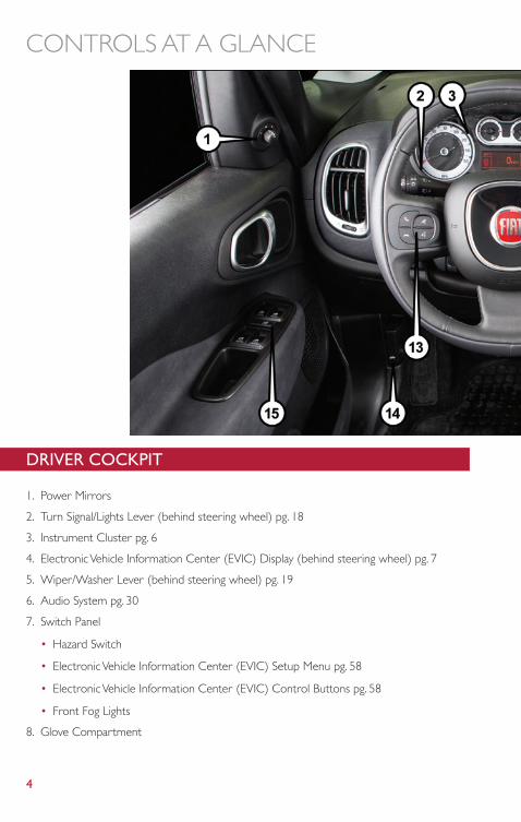
DRIVER COCKPIT
1. Power Mirrors
2. Turn Signal/Lights Lever (behind steering wheel) pg. 18
3. Instrument Cluster pg. 6
4. Electronic Vehicle Information Center (EVIC) Display (behind steering wheel) pg. 7
5. Wiper/Washer Lever (behind steering wheel) pg. 19
6. Audio System pg. 30
7. Switch Panel
• Hazard Switch
• Electronic Vehicle Information Center (EVIC) Setup Menu pg. 58
• Electronic Vehicle Information Center (EVIC) Control Buttons pg. 58
• Front Fog Lights
8. Glove Compartment
CONTROLS AT A GLANCE
4
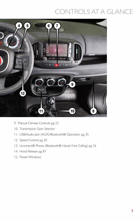
9. Manual Climate Controls pg. 22
10. Transmission Gear Selector
11. USB/Audio Jack (AUX)/Bluetooth® Operation pg. 35
12. Speed Control pg. 20
13. Uconnect® Phone (Bluetooth® Hands Free Calling) pg. 36
14. Hood Release pg. 87
15. Power Windows
CONTROLS AT A GLANCE
5
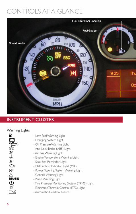
INSTRUMENT CLUSTER
Warning Lights- Low Fuel Warning Light- Charging System Light- Oil Pressure Warning Light- Anti-Lock Brake (ABS) Light- Air Bag Warning Light- Engine Temperature Warning Light- Seat Belt Reminder Light- Malfunction Indicator Light (MIL)- Power Steering System Warning Light- Generic Warning Light
BRAKE - Brake Warning Light- Tire Pressure Monitoring System (TPMS) Light- Electronic Throttle Control (ETC) Light- Automatic Gearbox Failure
CONTROLS AT A GLANCE
6
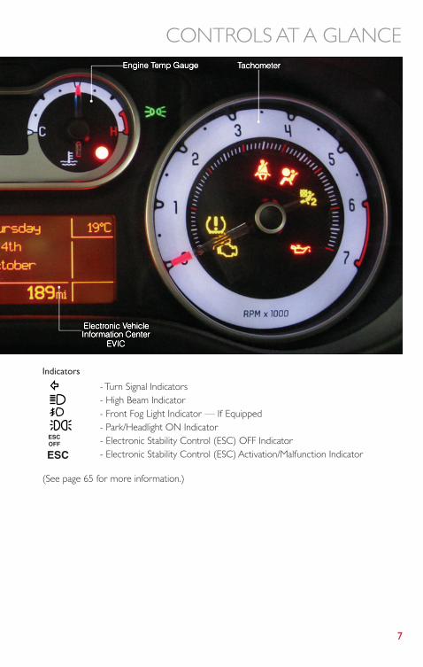
Indicators
- Turn Signal Indicators- High Beam Indicator- Front Fog Light Indicator — If Equipped- Park/Headlight ON Indicator- Electronic Stability Control (ESC) OFF Indicator- Electronic Stability Control (ESC) Activation/Malfunction Indicator
(See page 65 for more information.)
CONTROLS AT A GLANCE
7
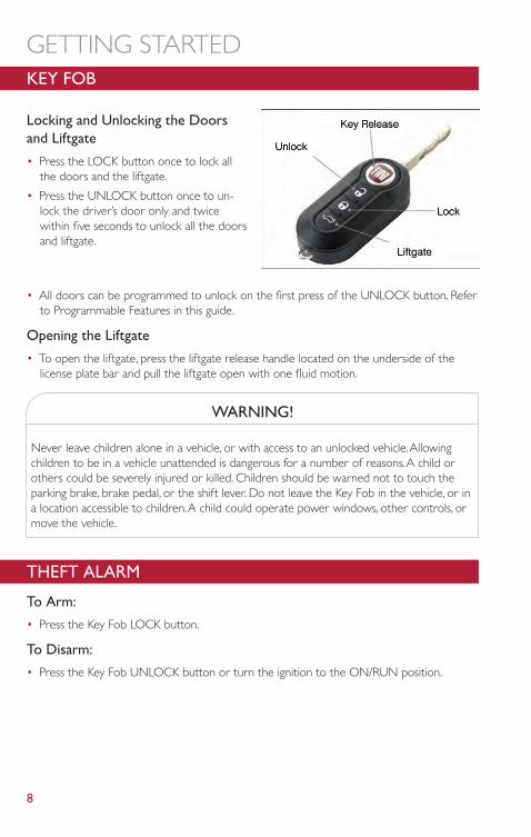
KEY FOB
Locking and Unlocking the Doorsand Liftgate
• Press the LOCK button once to lock allthe doors and the liftgate.
• Press the UNLOCK button once to un-lock the driver’s door only and twicewithin five seconds to unlock all the doorsand liftgate.
• All doors can be programmed to unlock on the first press of the UNLOCK button. Referto Programmable Features in this guide.
Opening the Liftgate
• To open the liftgate, press the liftgate release handle located on the underside of thelicense plate bar and pull the liftgate open with one fluid motion.
WARNING!
Never leave children alone in a vehicle, or with access to an unlocked vehicle.Allowingchildren to be in a vehicle unattended is dangerous for a number of reasons.A child orothers could be severely injured or killed. Children should be warned not to touch theparking brake, brake pedal, or the shift lever. Do not leave the Key Fob in the vehicle, or ina location accessible to children.A child could operate power windows, other controls, ormove the vehicle.
THEFT ALARM
To Arm:
• Press the Key Fob LOCK button.
To Disarm:
• Press the Key Fob UNLOCK button or turn the ignition to the ON/RUN position.
GETTING STARTED
8
POWER DOOR LOCKS• Press the central LOCK/UNLOCK button located on the instrument panel, in the switch
bank below the radio.The button has an LED that indicates whether the doors arelocked or unlocked.• LED ON: doors locked. Pressing the central LOCK/UNLOCK button once will unlock
all doors.The LED will switch off once the doors are unlocked.• LED OFF: doors unlocked. Pressing the central LOCK/UNLOCK button once will lock
all doors.The LED will switch on once the doors are locked.
• Once the doors have been locked with the RKE transmitter, it will no longer be possibleto unlock them by pressing central LOCK/UNLOCK button.
NOTE:With central locking active (LED ON), opening one of the front doors, it is possible to per-form a central unlocking (LED OFF).With central locking active (LED ON), in order toopen one of the rear passenger doors, it is necessary pulling the internal door handle twice.With one of the rear door open (LED OFF), the unlocking is performed only for that door,not for all the vehicle.
• To unlock the front doors, pull the inside door handle to the first detent. If the reardoors are locked, you must pull the door handle once to unlock the door and pull thedoor handle a second time to open the door.
WARNING!
• Do not leave children or animals inside parked vehicles in hot weather. Interior heatbuild-up may cause serious injury or death.
• For personal security and safety in the event of an collision, lock the vehicle doors asyou drive as well as when you park and leave the vehicle.
• Before exiting a vehicle, always turn the vehicle OFF, apply the parking brake, shift theautomatic transmission into PARK or the manual transmission into REVERSE, andremove the Key Fob from the ignition.When leaving the vehicle, always lock yourvehicle.
• Never leave children alone in a vehicle, or with access to an unlocked vehicle.• Allowing children to be in a vehicle unattended is dangerous for a number of rea-
sons.A child or others could be seriously or fatally injured. Children should bewarned not to touch the parking brake, brake pedal or the shift lever.
• Do not leave the Key Fob in or near the vehicle, or in a location accessible to child.Achild could operate power windows, other controls, or move the vehicle.
GETTING STARTED
9
CAUTION!
An unlocked vehicle is an invitation to thieves.Always remove the key from the ignitionand lock all of the doors when leaving the vehicle unattended.
Doors Lock With One Or More Doors Open
• It is possible locking the vehicle through the RKE, internal button or external key pawl,also if one or more doors are open.At lock command request, LED is switched ON.Atclosing of the last door, the vehicle maintains the central locking status if key is not in-serted in Ignition Device, otherwise the vehicle will be unlocked and the LED will beswitched OFF.
NOTE:If the key is not inserted in the ignition switch, but is inside the vehicle, the system does notrecognize the presence of the key and after the closing of last door, the vehicle remainslocked.
SEAT BELT• Be sure everyone in your vehicle is in a seat and using a seat belt properly.
• Position the lap belt across your thighs, below your abdomen.To remove slack in the lapportion, pull up a bit on the shoulder belt.To loosen the lap belt if it is too tight, tilt thelatch plate and pull on the lap belt.A snug belt reduces the risk of sliding under the beltin a collision.
• Position the shoulder belt on your chest so that it is comfortable and not resting on yourneck.The retractor will withdraw any slack in the belt.
• A shoulder belt placed behind you will not protect you from injury during a collision.Youare more likely to hit your head in a collision if you do not wear your shoulder belt.Thelap and shoulder belt are meant to be used together.
• A belt that is too loose will not protect you properly. In a sudden stop you could movetoo far forward, increasing the possibility of injury.Wear your seat belt snugly.
• A frayed or torn belt could rip apart in a collision and leave you with no protection. In-spect the belt system periodically, checking for cuts, frays, or loose parts. Damaged partsmust be replaced immediately. Do not disassemble or modify the system. Seat belt as-semblies must be replaced after a collision if they have been damaged (bent retractor,torn webbing, etc.).
• The seat belts for both front seating positions are equipped with pretensioning devicesthat are designed to remove slack from the seat belt in the event of a collision.
• A deployed pretensioner or a deployed air bag must be replaced immediately.
GETTING STARTED
10

WARNING!
In a collision, you and your passengers can suffer much greater injuries if you are not buck-led up properly.You can strike the interior of your vehicle or other passengers, or you canbe thrown out of the vehicle.Always be sure you and others in your vehicle are buckledup properly.
SUPPLEMENTAL RESTRAINT SYSTEM (SRS) - AIR BAGS• This vehicle has Advanced Front Air Bags for both the driver and right front passenger as
a supplement to the seat belt restraint system.The Advanced Front Air Bags will not de-ploy in every type of collision.
• Advanced Front Air Bags are designed to provide additional protection by supplementingthe seat belts in certain frontal collisions depending on several factors, including the se-verity and type of collision.Advanced Front Air Bags are not expected to reduce the riskof injury in rear, side, or rollover collisions.
• This vehicle is equipped with Supplemental Side Air Bag Inflatable Curtains to protect thedriver, front and rear passengers sitting next to a window.
• This vehicle is equipped with Supplemental Seat-Mounted Side Air Bags to provide en-hanced protection to help protect an occupant during a side impact.
• This vehicle is equipped with Supplemental Driver Side Knee Air Bag to provide en-hanced protection and work together with the Driver Advanced Front Air Bag during afrontal impact.
• If the Air Bag Warning Light is not on during starting, stays on, or turns on whiledriving, have the vehicle serviced by an authorized studio immediately.
• Refer to the Owner's Manual on the DVD for further details regarding the SupplementalRestraint System (SRS).
GETTING STARTED
11
WARNING!
• Relying on the air bags alone could lead to more severe injuries in a collision.The airbags work with your seat belt to restrain you properly. In some collisions, the air bagswon't deploy at all.Always wear your seat belts even though you have air bags.
• Being too close to the steering wheel or instrument panel during Advanced Front AirBag deployment could cause serious injury, including death.Air bags need room toinflate. Sit back, comfortably extending your arms to reach the steering wheel orinstrument panel.
• Supplemental Side Air Bag Inflatable Curtains and Supplemental Seat-Mounted SideAir Bags need room to inflate. Do not lean against the door or window. Sit upright inthe center of the seat.
• Being too close to the Supplemental Side Air Bag Inflatable Curtain and/or Seat-Mounted Side Air Bag during deployment could cause you to be severely injured orkilled.
• Do not drive your vehicle after the air bags have deployed. If you are involved inanother collision, the air bags will not be in place to protect you.
• After any collision, the vehicle should be taken to an authorized studio immediately.
CHILD RESTRAINTS• Children 12 years and under should ride properly buckled up in a rear seat, if available.
According to crash statistics, children are safer when properly restrained in the rear seatsrather than in the front.
• Every state in the United States and all Canadian provinces require that small childrenride in proper restraint systems.This is the law, and you can be prosecuted for ignoring it.
Installing The LATCH Compatible Child Restraint System
• Your vehicle's second row passenger seats are equipped with the child restraint anchor-age system called LATCH, which stands for Lower Anchors and Tether for CHildren.LATCH child restraint anchorage systems are installed in both rear seating positions.
GETTING STARTED
12
• NEVER install compatible child seats so that two seats share a common lower anchorage.
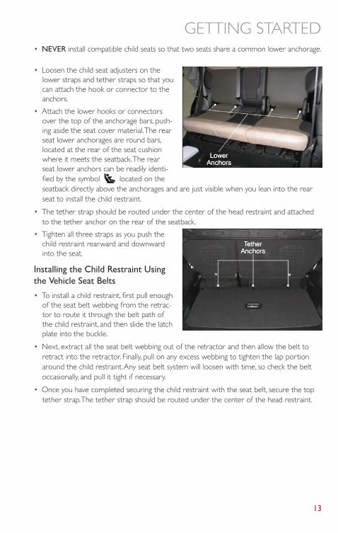
• Loosen the child seat adjusters on thelower straps and tether straps so that youcan attach the hook or connector to theanchors.
• Attach the lower hooks or connectorsover the top of the anchorage bars, push-ing aside the seat cover material.The rearseat lower anchorages are round bars,located at the rear of the seat cushionwhere it meets the seatback.The rearseat lower anchors can be readily identi-fied by the symbol located on theseatback directly above the anchorages and are just visible when you lean into the rearseat to install the child restraint.
• The tether strap should be routed under the center of the head restraint and attachedto the tether anchor on the rear of the seatback.
• Tighten all three straps as you push thechild restraint rearward and downwardinto the seat.
Installing the Child Restraint Usingthe Vehicle Seat Belts
• To install a child restraint, first pull enoughof the seat belt webbing from the retrac-tor to route it through the belt path ofthe child restraint, and then slide the latchplate into the buckle.
• Next, extract all the seat belt webbing out of the retractor and then allow the belt toretract into the retractor. Finally, pull on any excess webbing to tighten the lap portionaround the child restraint.Any seat belt system will loosen with time, so check the beltoccasionally, and pull it tight if necessary.
• Once you have completed securing the child restraint with the seat belt, secure the toptether strap.The tether strap should be routed under the center of the head restraint.
GETTING STARTED
13
WARNING!
• In a collision, an unrestrained child, even a tiny baby, can become a projectile insidethe vehicle.The force required to hold even an infant on your lap could become sogreat that you could not hold the child, no matter how strong you are.The child andothers could be severely injured or killed.Any child riding in your vehicle should bein a proper restraint for the child's size.
• Improper installation of a child restraint to the LATCH anchorages can lead to failureof an infant or child restraint.The child could be severely injured or killed. Follow themanufacturer’s directions exactly when installing an infant or child restraint.
• An incorrectly anchored tether strap could lead to increased head motion and pos-sible injury to the child. Use only the anchor positions directly behind the child seatto secure a child restraint top tether strap.
• Rearward-facing child seats must never be used in the front seat of a vehicle with afront passenger air bag.An air bag deployment could cause severe injury or death toinfants in this position.
• This vehicle does not have a center seating position. Do not use the center lowerLATCH anchorages to install a child seat in the center of the back seat.
FRONT SEATS
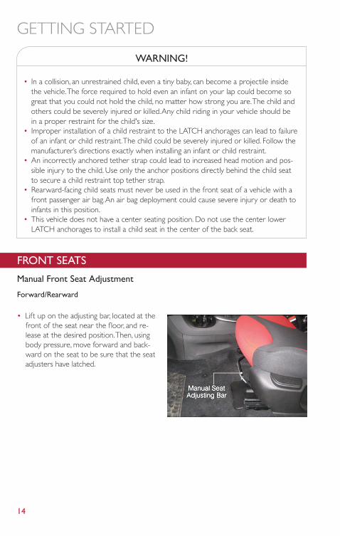
Manual Front Seat Adjustment
Forward/Rearward
• Lift up on the adjusting bar, located at thefront of the seat near the floor, and re-lease at the desired position.Then, usingbody pressure, move forward and back-ward on the seat to be sure that the seatadjusters have latched.
GETTING STARTED
14
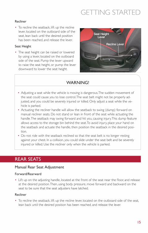
Recliner
• To recline the seatback, lift up the reclinelever, located on the outboard side of theseat, lean back until the desired positionhas been reached, and release the lever.
Seat Height
• The seat height can be raised or loweredby using a lever, located on the outboardside of the seat. Pump the lever upwardto raise the seat height, or pump the leverdownward to lower the seat height.
WARNING!
• Adjusting a seat while the vehicle is moving is dangerous.The sudden movement ofthe seat could cause you to lose control.The seat belt might not be properly ad-justed, and you could be severely injured or killed. Only adjust a seat while the ve-hicle is parked.
• Actuating the recliner handle will allow the seatback to swing (dump) forward onmanual recliner seats. Do not stand or lean in front of the seat while actuating thehandle.The seatback may swing forward and hit you, causing injury.This dump featureallows access to the storage bin behind the seat.To avoid injury, place your hand onthe seatback and actuate the handle, then position the seatback in the desired posi-tion.
• Do not ride with the seatback reclined so that the seat belt is no longer restingagainst your chest. In a collision, you could slide under the seat belt and be severelyinjured or killed. Use the recliner only when the vehicle is parked.
REAR SEATS
Manual Rear Seat Adjustment
Forward/Rearward
• Lift up on the adjusting handle, located at the front of the seat near the floor, and releaseat the desired position.Then, using body pressure, move forward and backward on theseat to be sure that the seat adjusters have latched.
Recliner
• To recline the seatback, lift up the recline lever, located on the outboard side of the seat,lean back until the desired position has been reached, and release the lever.
GETTING STARTED
15
Fold And Tumble Rear Seat
• Be sure that the front seats are fully upright and positioned forward.This will allow therear seat to fold down easily.
• Lift the seatback release lever located on the upper outboard side of the seat and foldthe seatback forward.
• To tumble the seat, lift upward on the recliner lever and slowly flip the entire seatforward.
WARNING!
• Adjusting a seat while the vehicle is moving is dangerous.The sudden movement ofthe seat could cause you to lose control.The seat belt might not be properly ad-justed, and you could be severely injured or killed. Only adjust a seat while the ve-hicle is parked.
• Actuating the recliner handle will allow the seatback to swing (dump) forward onmanual recliner seats. Do not stand or lean in front of the seat while actuating thehandle.The seatback may swing forward and hit you, causing injury.This dump featureallows access to the storage bin behind the seat.To avoid injury, place your hand onthe seatback and actuate the handle, then position the seatback in the desired posi-tion.
• Do not ride with the seatback reclined so that the seat belt is no longer restingagainst your chest. In a collision, you could slide under the seat belt and be severelyinjured or killed. Use the recliner only when the vehicle is parked.
GETTING STARTED
16
HEATED SEATS
Front Heated Seats
• The controls for the front heated seats are located on the outboard side of the seat.
• Press the switch once to turn on the heated seat. Press the switch a second time to turnoff the heated seat.
WARNING!
• Persons who are unable to feel pain to the skin because of advanced age, chronicillness, diabetes, spinal cord injury, medication, alcohol use, exhaustion or other physi-cal conditions must exercise care when using the seat heater. It may cause burnseven at low temperatures, especially if used for long periods of time.
• Do not place anything on the seat that insulates against heat, such as a blanket orcushion.This may cause the seat heater to overheat. Sitting in a seat that has beenoverheated could cause serious burns due to the increased surface temperature ofthe seat.
TILT/TELESCOPING STEERING COLUMN
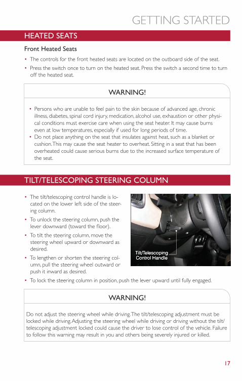
• The tilt/telescoping control handle is lo-cated on the lower left side of the steer-ing column.
• To unlock the steering column, push thelever downward (toward the floor).
• To tilt the steering column, move thesteering wheel upward or downward asdesired.
• To lengthen or shorten the steering col-umn, pull the steering wheel outward orpush it inward as desired.
• To lock the steering column in position, push the lever upward until fully engaged.
WARNING!
Do not adjust the steering wheel while driving.The tilt/telescoping adjustment must belocked while driving.Adjusting the steering wheel while driving or driving without the tilt/telescoping adjustment locked could cause the driver to lose control of the vehicle. Failureto follow this warning may result in you and others being severely injured or killed.
GETTING STARTED
17
ENGINE BREAK-IN RECOMMENDATIONS• A long break-in period is not required for the engine and drivetrain (transmission and
axle) in your vehicle.
• Drive moderately during the first 300 miles (500 km).After the initial 60 miles (100 km),speeds up to 50 or 55 mph (80 or 90 km/h) are desirable.
• While cruising, brief full-throttle acceleration within the limits of local traffic laws contrib-utes to a good break-in.Wide-open throttle acceleration in low gear can be detrimentaland should be avoided.
• The engine oil installed in the engine at the factory is a high-quality energy conservingtype lubricant. Oil changes should be consistent with anticipated climate conditions underwhich vehicle operations will occur. For the recommended viscosity and quality grades,refer to “Maintaining Your Vehicle”.
NOTE:A new engine may consume some oil during its first few thousand miles (kilometers) ofoperation.This should be considered a normal part of the break-in and not interpreted asan indication to an engine problem or malfunction.
CAUTION!
Never use Non-Detergent Oil or Straight Mineral Oil in the engine or damage may result.
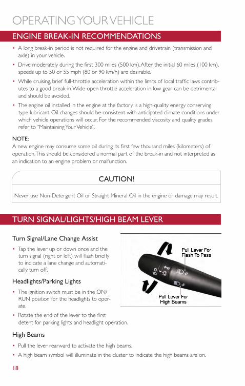
TURN SIGNAL/LIGHTS/HIGH BEAM LEVER
Turn Signal/Lane Change Assist
• Tap the lever up or down once and theturn signal (right or left) will flash brieflyto indicate a lane change and automati-cally turn off.
Headlights/Parking Lights
• The ignition switch must be in the ON/RUN position for the headlights to oper-ate.
• Rotate the end of the lever to the firstdetent for parking lights and headlight operation.
High Beams
• Pull the lever rearward to activate the high beams.
• A high beam symbol will illuminate in the cluster to indicate the high beams are on.
OPERATING YOUR VEHICLE
18
NOTE:For safe driving, turn off the high beams when oncoming traffic is present to prevent head-light glare and as a courtesy to other motorists.
Flash To Pass
• Pull the lever toward you to activate the high beams.The high beams will remain on untilthe lever is released.
Headlight Delay (Follow Me Home)
• Within two minutes of the ignition switch being turned to the OFF/LOCK position or theignition key being removed from the ignition, pull the turn signal lever toward the steer-ing wheel.
• Each movement of the lever toward the steering wheel will increase the illumination pe-riod by 30 seconds, up to a maximum of 210 seconds.
• To deactivate, pull the multifunction lever toward the steering wheel and hold it for morethan two seconds.
NOTE:Activation of Follow Me Home is only enabled once per key cycle and steps must be re-peated each time you want to activate it.
Fog Lights
• Push the fog light button, located on the center stack of the instrument panel just belowthe radio, once to turn on the fog lights.
• Push the button a second time to turn the fog lights off.
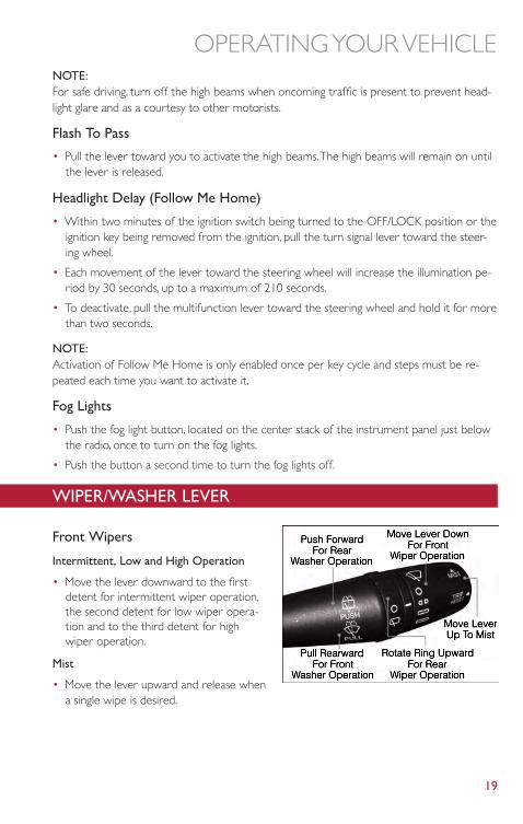
WIPER/WASHER LEVER
Front Wipers
Intermittent, Low and High Operation
• Move the lever downward to the firstdetent for intermittent wiper operation,the second detent for low wiper opera-tion and to the third detent for highwiper operation.
Mist
• Move the lever upward and release whena single wipe is desired.
OPERATING YOUR VEHICLE
19
NOTE:The mist feature does not activate the washer pump; therefore, no washer fluid will besprayed on the windshield.The wash function must be activated in order to spray the wind-shield with washer fluid.
Washer Operation
• Pull the lever toward you and hold for as long as spray is desired.
Rear Wiper
Rear Wiper Operation
• Rotate the windshield wiper lever center ring upwards to activate the rear wiper.
Rear Washer Operation
• Push the lever forward and hold for as long as spray is desired.
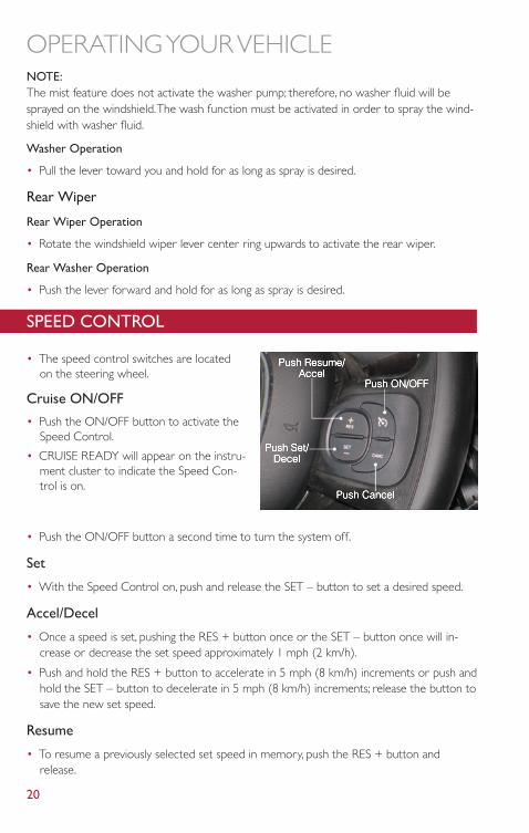
SPEED CONTROL
• The speed control switches are locatedon the steering wheel.
Cruise ON/OFF
• Push the ON/OFF button to activate theSpeed Control.
• CRUISE READY will appear on the instru-ment cluster to indicate the Speed Con-trol is on.
• Push the ON/OFF button a second time to turn the system off.
Set
• With the Speed Control on, push and release the SET – button to set a desired speed.
Accel/Decel
• Once a speed is set, pushing the RES + button once or the SET – button once will in-crease or decrease the set speed approximately 1 mph (2 km/h).
• Push and hold the RES + button to accelerate in 5 mph (8 km/h) increments or push andhold the SET – button to decelerate in 5 mph (8 km/h) increments; release the button tosave the new set speed.
Resume
• To resume a previously selected set speed in memory, push the RES + button andrelease.
OPERATING YOUR VEHICLE
20
Cancel
• Push the CANCEL button, or apply the brakes to cancel the set speed and maintain theset speed memory.
• Push the ON/OFF button to turn the system off and erase the set speed memory.
WARNING!
• Leaving the Electronic Speed Control system on when not in use is dangerous.Youcould accidentally set the system or cause it to go faster than you want.You couldlose control and have a collision.Always leave the Electronic Speed Control systemoff when you are not using it.
• Electronic Speed Control can be dangerous where the system cannot maintain aconstant speed.Your vehicle could go too fast for the conditions, and you could losecontrol.A collision could be the result. Do not use Electronic Speed Control in heavytraffic or on roads that are winding, icy, snow-covered or slippery.
OPERATING YOUR VEHICLE
21
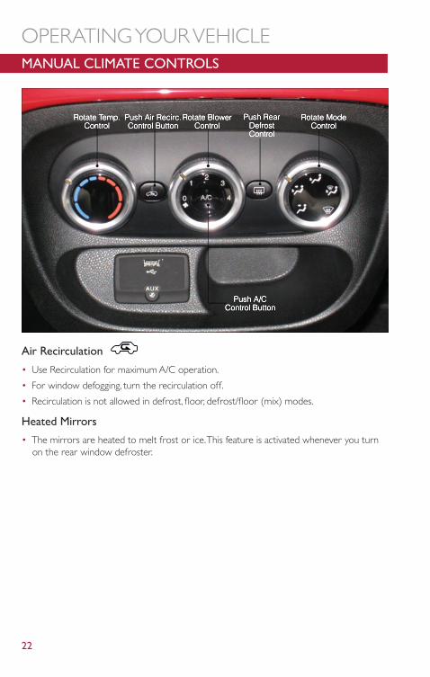
MANUAL CLIMATE CONTROLS
Air Recirculation
• Use Recirculation for maximum A/C operation.
• For window defogging, turn the recirculation off.
• Recirculation is not allowed in defrost, floor, defrost/floor (mix) modes.
Heated Mirrors
• The mirrors are heated to melt frost or ice.This feature is activated whenever you turnon the rear window defroster.
OPERATING YOUR VEHICLE
22
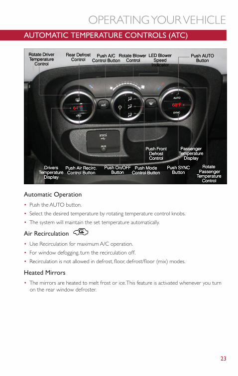
AUTOMATIC TEMPERATURE CONTROLS (ATC)
Automatic Operation
• Push the AUTO button.
• Select the desired temperature by rotating temperature control knobs.
• The system will maintain the set temperature automatically.
Air Recirculation
• Use Recirculation for maximum A/C operation.
• For window defogging, turn the recirculation off.
• Recirculation is not allowed in defrost, floor, defrost/floor (mix) modes.
Heated Mirrors
• The mirrors are heated to melt frost or ice.This feature is activated whenever you turnon the rear window defroster.
OPERATING YOUR VEHICLE
23
REAR PARK ASSIST• If an object is detected behind the rear bumper while the vehicle is in REVERSE, a chime
will sound.The chime rate will change depending on the distance of the object, gettingfaster as the object gets closer to the bumper.The chime will become continuous whenthe distance between the vehicle and the obstacle is less than 12 inches (30 cm).
POWER SUNROOF• The power sunroof roof switch is located in the overhead console.
To Open
• Press and hold the power sunroof switch rearward for approximately two seconds andthe sunroof will stop at the vented position. Press the switch a second time and hold forapproximately one second and release, the sunroof will open fully, then stop automatically.This is called “Express Open”. During Express Open operation, any movement of thesunroof switch will stop the sunroof.
To Close
• With the sunroof in the full open position, pull the power sunroof button and hold it forapproximately one second, the sunroof will return to the completely close position. Dur-ing Express Close operation, any movement of the sunroof switch will stop the sunroof.
Power Sun Blind
• Pull the power sun blind switch and the blind will move towards the rear part of the car,until it is fully open.With the blind fully open pull the power sun blind switch and theblind will move towards the front part of the car, until it is fully closed.
NOTE:During the automatic opening and closing stages, if the power sun blind switch is pulledagain it will stop the blind movement.
WARNING!
• Do not let children play with the sunroof, or leave children unattended in the ve-hicle, and do not leave the key in or near the vehicle (or in a location accessible tochildren). Occupants, particularly unattended children, can become entrapped by thepower sunroof while operating the power sunroof switch. Such entrapment mayresult in serious injury or death.
• In a collision, there is a greater risk of being thrown from a vehicle with an opensunroof.You could also be seriously injured or killed.Always fasten your seat beltproperly and make sure all passengers are properly secured.
• Do not allow small children to operate the sunroof. Never allow your fingers, otherbody parts, or any object to project through the sunroof opening. Injury may result.
OPERATING YOUR VEHICLE
24
SIX-SPEED AUTOMATIC TRANSMISSION• This vehicle may be equipped with a fuel efficient Dual-Dry Clutch, Six Speed Automatic
Transmission.This transmission offers a sportier driving experience with fasterAutoStick® shifting.
• During low-speed driving conditions in first gear, vehicle momentum changes may feelexaggerated in response to changes in accelerator pedal position.This behavior is normaland is similar to vehicles equipped with a manual transmission.
NOTE:
• Very aggressive driving may result in some clutch odor similar to a manual transmission.An active warning message will display in the Instrument Cluster if cool down actions areneeded.
• The first few shifts on a new vehicle may be somewhat abrupt.This is a normal condition,and precision shifts will develop within a few hundred miles (kilometers).
• At low speeds you may hear mechanical noises similar to a manual transmission as thetransmission changes gears.These noises are normal and will not damage the transmis-sion.
• Before and after the engine is started, you may hear a hydraulic pump for a short periodof time.This noise is normal and will not damage the transmission.
Shifting The Transmission
• The transmission shift lever position (PRND) is displayed both on the shift lever and inthe Electronic Vehicle Information Center (EVIC).
• To drive, depress the brake pedal, press the button on the front of the shift lever andmove the shift lever from PARK or NEUTRAL to the DRIVE position.
• Manual shifts can also be made using the AutoStick® shift control.
• This transmission is programmed to prevent shifting from REVERSE to DRIVE or DRIVEto REVERSE, if vehicle speed is above 6 mph (10 km/h).This safety feature helps protectyour transmission from damage.
NOTE:
• When stopped on an incline, it is recommended that you always hold the vehicle in placeusing the brakes. On steep inclines, Hill Start Assist (HSA) will temporarily hold the car inposition when the brake pedal is released. If the accelerator pedal is not applied after ashort time, the car will roll back. Either reapply the brake (to hold the vehicle) or pressthe accelerator to climb the hill.
• During acceleration, gear changes will feel smooth compared to a vehicle with a tradi-tional manual transmission.This is a benefit of the dual clutch design that avoids powerloss during up-shifts.
Instrument Cluster Messages
• Messages will be displayed in the instrument cluster (if equipped with an EVIC) to alertthe driver when certain conditions occur.These messages are described below.
OPERATING YOUR VEHICLE
25
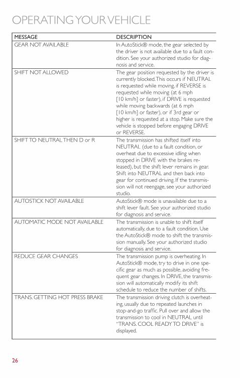
MESSAGE DESCRIPTIONGEAR NOT AVAILABLE In AutoStick® mode, the gear selected by
the driver is not available due to a fault con-dition. See your authorized studio for diag-nosis and service.
SHIFT NOT ALLOWED The gear position requested by the driver iscurrently blocked.This occurs if NEUTRALis requested while moving, if REVERSE isrequested while moving (at 6 mph[10 km/h] or faster), if DRIVE is requestedwhile moving backwards (at 6 mph[10 km/h] or faster), or if 3rd gear orhigher is requested at a stop. Make sure thevehicle is stopped before engaging DRIVEor REVERSE.
SHIFT TO NEUTRAL THEN D or R The transmission has shifted itself intoNEUTRAL (due to a fault condition, oroverheat due to excessive idling whenstopped in DRIVE with the brakes re-leased), but the shift lever remains in gear.Shift into NEUTRAL and then back intogear for continued driving. If the transmis-sion will not reengage, see your authorizedstudio.
AUTOSTICK NOT AVAILABLE AutoStick® mode is unavailable due to ashift lever fault. See your authorized studiofor diagnosis and service.
AUTOMATIC MODE NOT AVAILABLE The transmission is unable to shift itselfautomatically, due to a fault condition. Usethe AutoStick® mode to shift the transmis-sion manually. See your authorized studiofor diagnosis and service.
REDUCE GEAR CHANGES The transmission pump is overheating. InAutoStick® mode, try to drive in one spe-cific gear as much as possible, avoiding fre-quent gear changes. In DRIVE, the transmis-sion will automatically modify its shiftschedule to reduce the number of shifts.
TRANS. GETTING HOT PRESS BRAKE The transmission driving clutch is overheat-ing, usually due to repeated launches instop-and-go traffic. Pull over and allow thetransmission to cool in NEUTRAL until“TRANS. COOL READY TO DRIVE” isdisplayed.
OPERATING YOUR VEHICLE
26
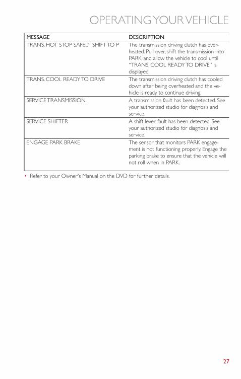
MESSAGE DESCRIPTIONTRANS. HOT STOP SAFELY SHIFT TO P The transmission driving clutch has over-
heated. Pull over, shift the transmission intoPARK, and allow the vehicle to cool until“TRANS. COOL READY TO DRIVE” isdisplayed.
TRANS. COOL READY TO DRIVE The transmission driving clutch has cooleddown after being overheated and the ve-hicle is ready to continue driving.
SERVICE TRANSMISSION A transmission fault has been detected. Seeyour authorized studio for diagnosis andservice.
SERVICE SHIFTER A shift lever fault has been detected. Seeyour authorized studio for diagnosis andservice.
ENGAGE PARK BRAKE The sensor that monitors PARK engage-ment is not functioning properly. Engage theparking brake to ensure that the vehicle willnot roll when in PARK.
• Refer to your Owner's Manual on the DVD for further details.
OPERATING YOUR VEHICLE
27
ADDING FUEL
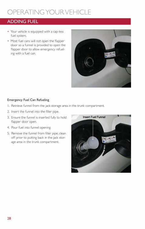
• Your vehicle is equipped with a cap-lessfuel system.
• Most fuel cans will not open the flapperdoor so a funnel is provided to open theflapper door to allow emergency refuel-ing with a fuel can.
Emergency Fuel Can Refueling
1. Retrieve funnel from the jack storage area in the trunk compartment.
2. Insert the funnel into the filler pipe.
3. Ensure the funnel is inserted fully to holdflapper door open.
4. Pour fuel into funnel opening.
5. Remove the funnel from filler pipe, cleanoff prior to putting back in the jack stor-age area in the trunk compartment.
OPERATING YOUR VEHICLE
28
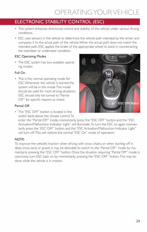
ELECTRONIC STABILITY CONTROL (ESC)• This system enhances directional control and stability of the vehicle under various driving
conditions.
• ESC uses sensors in the vehicle to determine the vehicle path intended by the driver andcompares it to the actual path of the vehicle.When the actual path does not match theintended path, ESC applies the brake of the appropriate wheel to assist in counteractingthe oversteer or understeer condition.
ESC Operating Modes
• The ESC system has two available operat-ing modes.
Full On
• This is the normal operating mode forESC.Whenever the vehicle is started thesystem will be in this mode.This modeshould be used for most driving situations.ESC should only be turned to “PartialOff” for specific reasons as noted.
Partial Off
• The “ESC OFF” button is located in theswitch bank above the climate control.Toenter the “Partial Off” mode, momentarily press the “ESC OFF” button and the “ESCActivation/Malfunction Indicator Light” will illuminate.To turn the ESC on again, momen-tarily press the “ESC OFF” button and the “ESC Activation/Malfunction Indicator Light”will turn off.This will restore the normal “ESC On” mode of operation.
NOTE:To improve the vehicle’s traction when driving with snow chains, or when starting off indeep snow, sand, or gravel, it may be desirable to switch to the “Partial Off” mode by mo-mentarily pressing the “ESC OFF” button. Once the situation requiring “Partial Off” mode isovercome, turn ESC back on by momentarily pressing the “ESC OFF” button.This may bedone while the vehicle is in motion.
OPERATING YOUR VEHICLE
29
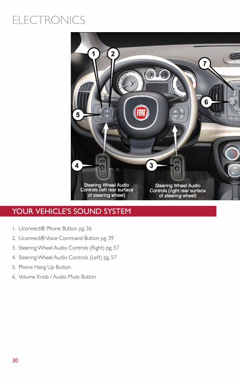
YOUR VEHICLE'S SOUND SYSTEM
1. Uconnect® Phone Button pg. 36
2. Uconnect® Voice Command Button pg. 39
3. Steering Wheel Audio Controls (Right) pg. 57
4. Steering Wheel Audio Controls (Left) pg. 57
5. Phone Hang Up Button
6. Volume Knob / Audio Mute Button
ELECTRONICS
30
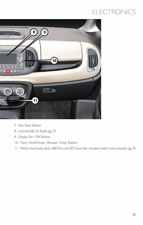
7. Disc Eject Button
8. Uconnect® 5.0 Radio pg. 33
9. Display On / Off Button
10. Tune / Scroll Knob / Browse / Enter Button
11. Media Hub:Audio Jack, USB Port, and SD Card Slot (located inside front console) pg. 35
ELECTRONICS
31
IDENTIFYING YOUR RADIO
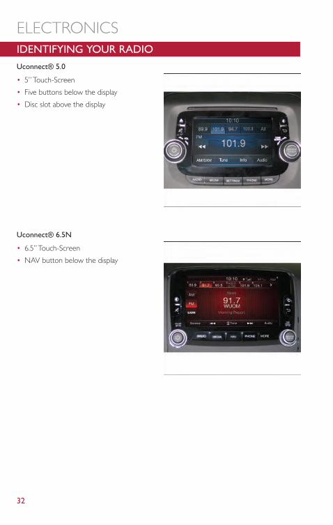
Uconnect® 5.0
• 5” Touch-Screen
• Five buttons below the display
• Disc slot above the display
Uconnect® 6.5N
• 6.5” Touch-Screen
• NAV button below the display
ELECTRONICS
32
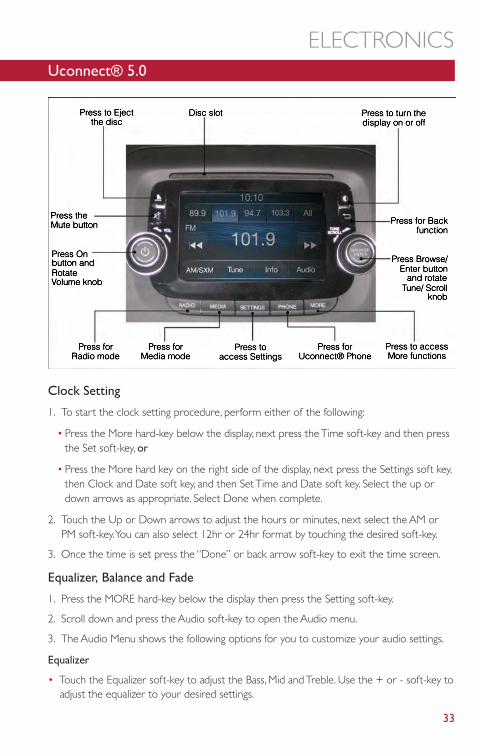
Uconnect® 5.0
Clock Setting
1. To start the clock setting procedure, perform either of the following:
• Press the More hard-key below the display, next press the Time soft-key and then pressthe Set soft-key, or
• Press the More hard key on the right side of the display, next press the Settings soft key,then Clock and Date soft key, and then Set Time and Date soft key. Select the up ordown arrows as appropriate. Select Done when complete.
2. Touch the Up or Down arrows to adjust the hours or minutes, next select the AM orPM soft-key.You can also select 12hr or 24hr format by touching the desired soft-key.
3. Once the time is set press the “Done” or back arrow soft-key to exit the time screen.
Equalizer, Balance and Fade
1. Press the MORE hard-key below the display then press the Setting soft-key.
2. Scroll down and press the Audio soft-key to open the Audio menu.
3. The Audio Menu shows the following options for you to customize your audio settings.
Equalizer
• Touch the Equalizer soft-key to adjust the Bass, Mid and Treble. Use the + or - soft-key toadjust the equalizer to your desired settings.
ELECTRONICS
33
Balance/Fade
• Touch the Balance/Fade soft-key to adjust the sound from the speakers. Use the arrowsoft-keys to adjust the sound level from the front and rear or right and left side speakers.Touch the Center “C” soft-key to reset the balance and fade to the factory setting.
Speed Adjusted Volume
• Touch the Speed Adjusted Volume soft-key to select between OFF, 1, 2 or 3.This will de-crease the radio volume relative to a decrease in vehicle speed.
Loudness
• Touch the Loudness soft-key to select the Loudness feature.When this feature is acti-vated it improves sound quality at lower volumes.
Surround Sound
• Touch the Surround Sound soft-key, select On or Off followed by pressing the arrowback soft-key.When this feature is activated, it provides simulated surround sound mode.
Radio Operation
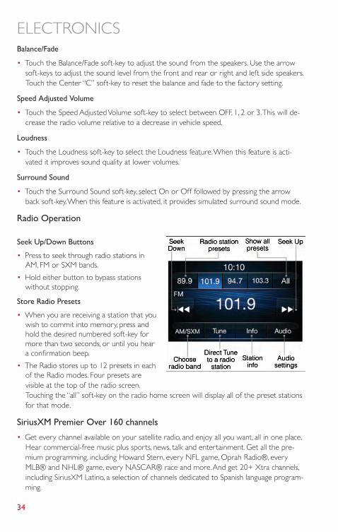
Seek Up/Down Buttons
• Press to seek through radio stations inAM, FM or SXM bands.
• Hold either button to bypass stationswithout stopping.
Store Radio Presets
• When you are receiving a station that youwish to commit into memory, press andhold the desired numbered soft-key formore than two seconds, or until you heara confirmation beep.
• The Radio stores up to 12 presets in eachof the Radio modes. Four presets arevisible at the top of the radio screen.Touching the “all” soft-key on the radio home screen will display all of the preset stationsfor that mode.
SiriusXM Premier Over 160 channels
• Get every channel available on your satellite radio, and enjoy all you want, all in one place.Hear commercial-free music plus sports, news, talk and entertainment. Get all the pre-mium programming, including Howard Stern, every NFL game, Oprah Radio®, everyMLB® and NHL® game, every NASCAR® race and more.And get 20+ Xtra channels,including SiriusXM Latino, a selection of channels dedicated to Spanish language program-ming.
ELECTRONICS
34
• To access SiriusXM Satellite Radio, press the “RADIO” hard-key and then the SXM soft-key.
• SiriusXM services require subscriptions, sold separately after the 12-month trial includedwith the new vehicle purchase. If you decide to continue your service at the end ofyour trial subscription, the plan you choose will automatically renew and bill at then-current rates until you call SiriusXM at 1-866-635-2349 for U.S. residents and1-888-539-7474 for Canadian residents to cancel. See SiriusXM Customer Agreementfor complete terms at www.siriusxm.com. All fees and programming subject to change.Our satellite service is available only to those at least 18 and older in the 48 contiguousUSA and D.C. Our Sirius satellite service is also available in PR (with coverage limitations).Our Internet radio service is available throughout our satellite service area and in AK andHI. © 2013 Sirius XM Radio Inc. Sirius, XM and all related marks and logos are trade-marks of Sirius XM Radio Inc.
USB/Audio Jack (AUX)/Bluetooth® Operation
USB/iPod®
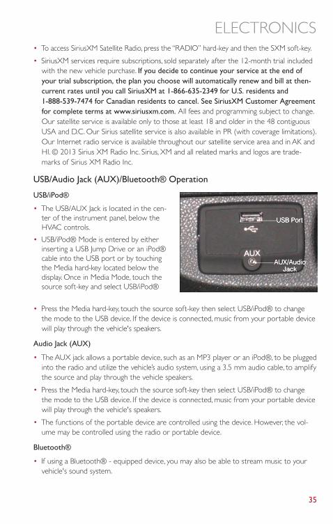
• The USB/AUX Jack is located in the cen-ter of the instrument panel, below theHVAC controls.
• USB/iPod® Mode is entered by eitherinserting a USB Jump Drive or an iPod®cable into the USB port or by touchingthe Media hard-key located below thedisplay. Once in Media Mode, touch thesource soft-key and select USB/iPod®
• Press the Media hard-key, touch the source soft-key then select USB/iPod® to changethe mode to the USB device. If the device is connected, music from your portable devicewill play through the vehicle's speakers.
Audio Jack (AUX)
• The AUX jack allows a portable device, such as an MP3 player or an iPod®, to be pluggedinto the radio and utilize the vehicle’s audio system, using a 3.5 mm audio cable, to amplifythe source and play through the vehicle speakers.
• Press the Media hard-key, touch the source soft-key then select USB/iPod® to changethe mode to the USB device. If the device is connected, music from your portable devicewill play through the vehicle's speakers.
• The functions of the portable device are controlled using the device. However, the vol-ume may be controlled using the radio or portable device.
Bluetooth®
• If using a Bluetooth® - equipped device, you may also be able to stream music to yourvehicle's sound system.
ELECTRONICS
35
• Press the Media hard-key, touch the source soft-key then select Bluetooth® to changethe mode to Bluetooth®. If the device is paired, music from your portable device willplay through the vehicle's speakers.
Uconnect® 5.0 Available Media Hubs
Uconnect® 5.0Media Hub (USB,AUX Ports)S
S = Standard Equipment
Uconnect® Phone (Bluetooth® HANDS FREE CALLING)
• If the Uconnect® Phone Button exists on your steering wheel, then you have theUconnect® Phone features.
• The Uconnect® Phone is a voice-activated, hands-free, in-vehicle communications systemwith Voice Command Capability (see Voice Command section).
• The Uconnect® Phone allows you to dial a phone number with your mobile phone usingsimple voice commands or using screen soft-keys.
• Refer to the Understand The Features Of Your Vehicle section of your vehicle's Owner'sManual on the DVD for further details.
NOTE:The Uconnect® Phone requires a mobile phone equipped with the Bluetooth® Hands-Free Profile,Version 1.0 or higher. For Uconnect® Customer Support: U.S. residents visitwww.UconnectPhone.com or call 1-888-242-6342. Canadian Residents visitwww.UconnectPhone.com or call 1-800-465–2001 (English) or 1-800-387-9983 (French).
Pairing a Phone
• To use the Uconnect® Phone feature, you must first pair your Bluetooth® phone withthe Uconnect® system.
Start pairing procedure on the radio
• Press the Phone hard-key and then the Settings soft-key. Next, touch the Add Devicesoft-key.
• Uconnect® Phone will display an “In progress” screen while the system is connecting.
Start pairing procedure on mobile phone
• Search for available devices on your Bluetooth® enabled mobile phone.This is usuallywithin Settings or Options under “Bluetooth”. See your mobile phone’s manual for details.
• When your phone finds the system, select “Uconnect” as the paired device.You may beprompted by your phone to download the phonebook.This is so you can make calls bysaying the name of your contact (PBAP-Phone Book Access Profile).
Complete the pairing procedure
• When prompted on the phone, verify with radio password shown on the Uconnect®Screen.
ELECTRONICS
36
• If your phone asks you to accept a connection request from Uconnect®, select “Yes”. Ifavailable, check the box telling it not to ask again – that way your phone will automaticallyconnect each time you start the vehicle.
Select the mobile phone's priority level
• When the pairing process has successfully completed, the system will prompt you tochoose whether or not this is your favorite phone. Selecting “Yes” will make this phonethe highest priority.This phone will take precedence over other paired phones withinrange. Only one phone can be paired at a time.
• You are now ready to make hands-free calls. Press the Uconnect® Phone button on yoursteering wheel to begin.
Making A Phone Call
• Press the Uconnect® Phone button .
• After the BEEP, say “dial” then the number (or “call” then the name as listed in yourphone; see Phonebook).
NOTE:You can also initiate a call by using the touch-screen on the Phone main screen.
Receiving A Call – Accept (And End)
• When an incoming call rings/is announced on Uconnect®, press the Phone button .
• To end a call, press the Hang Up or Phone button..
Mute (Or Unmute) Microphone During Call
• During a call, touch the mute soft-key on the Phone main screen to mute and unmutethe call.
Transfer Ongoing Call Between Handset And Vehicle
• During an on-going call, touch the Transfer soft-key on the Phone main screen to transferan on-going call between handset and vehicle.
Common Phone Commands (Examples)
• “Call John Smith”
• “Call John Smith mobile”
• “Dial 1 248 555 1212
• “Call Emergency”
• “Call Towing Assistance”
• “Redial”
ELECTRONICS
37
Phonebook
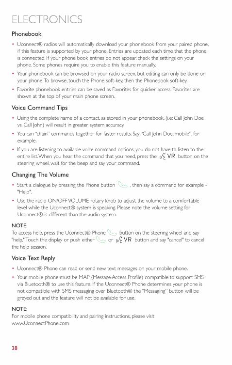
• Uconnect® radios will automatically download your phonebook from your paired phone,if this feature is supported by your phone. Entries are updated each time that the phoneis connected. If your phone book entries do not appear, check the settings on yourphone. Some phones require you to enable this feature manually.
• Your phonebook can be browsed on your radio screen, but editing can only be done onyour phone.To browse, touch the Phone soft-key, then the Phonebook soft-key.
• Favorite phonebook entries can be saved as Favorites for quicker access. Favorites areshown at the top of your main phone screen.
Voice Command Tips
• Using the complete name of a contact, as stored in your phonebook, (i.e; Call John Doevs. Call John) will result in greater system accuracy.
• You can “chain” commands together for faster results. Say “Call John Doe, mobile”, forexample.
• If you are listening to available voice command options, you do not have to listen to theentire list.When you hear the command that you need, press the button on thesteering wheel, wait for the beep and say your command.
Changing The Volume
• Start a dialogue by pressing the Phone button , then say a command for example -"Help".
• Use the radio ON/OFF VOLUME rotary knob to adjust the volume to a comfortablelevel while the Uconnect® system is speaking. Please note the volume setting forUconnect® is different than the audio system.
NOTE:To access help, press the Uconnect® Phone button on the steering wheel and say"help." Touch the display or push either or button and say "cancel" to cancelthe help session.
Voice Text Reply
• Uconnect® Phone can read or send new text messages on your mobile phone.
• Your mobile phone must be MAP (Message Access Profile) compatible to support SMSvia Bluetooth® to use this feature. If the Uconnect® Phone determines your phone isnot compatible with SMS messaging over Bluetooth® the “Messaging” button will begreyed out and the feature will not be available for use.
NOTE:For mobile phone compatibility and pairing instructions, please visitwww.UconnectPhone.com
ELECTRONICS
38
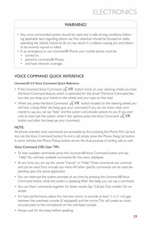
WARNING!
• Any voice commanded system should be used only in safe driving conditions follow-ing applicable laws regarding phone use.Your attention should be focused on safelyoperating the vehicle. Failure to do so may result in a collision causing you and othersto be severely injured or killed.
• In an emergency, to use Uconnect® Phone, your mobile phone must be:• turned on,• paired to Uconnect® Phone,• and have network coverage.
VOICE COMMAND QUICK REFERENCE
Uconnect® 5.0 Voice Command Quick Reference
• If the Uconnect Voice Command button exists on your steering wheel, you havethe Voice Command feature, which is optimized for the driver.The Voice Command fea-ture lets you keep your hands on the wheel, and your eyes on the road.
• When you press the Voice Command button located on the steering wheel, youwill hear a beep.After the beep, give your command. If you do not know what com-mands to say, you can say “help” and the system will provide options to you. If you everwish to interrupt the system while it lists options, press the Voice Commandbutton, and after the beep, say your command.
NOTE:All phone oriented voice commands are accessible by first pressing the Phone Pick Up but-ton, not the Voice Command button.To end a call, simply press the Phone Hang Up button.In some vehicles, the Phone Pickup button serves the dual purpose of ending calls as well.
Voice Command (VR) User TIPs
• To hear available commands, press the Uconnect® Voice Command button and say“Help”.You will hear available commands for the menu displayed.
• At any time, you can say the words “Cancel” or “Help”.These commands are universaland can be used from virtually any menu.All other specific commands can be used de-pending upon the active application.
• You can interrupt the system prompts at any time by pressing the Uconnect® VoiceCommand button while the system is speaking.After the beep, you can say a command.
• You can ‘chain’ commands together for faster results. Say “Call Joe Doe mobile”, for ex-ample.
• For best performance, adjust the rearview mirror to provide at least ½ in (1 cm) gapbetween the overhead console (if equipped) and the mirror.This will create an unob-structed path to the microphone on the overhead console.
• Always wait for the beep before speaking.
ELECTRONICS
39
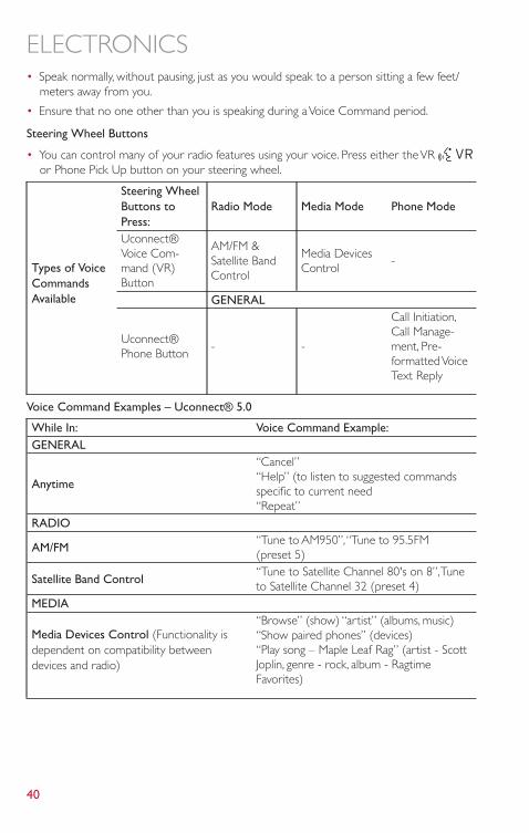
• Speak normally, without pausing, just as you would speak to a person sitting a few feet/meters away from you.
• Ensure that no one other than you is speaking during a Voice Command period.
Steering Wheel Buttons
• You can control many of your radio features using your voice. Press either the VRor Phone Pick Up button on your steering wheel.
Types of VoiceCommandsAvailable
Steering WheelButtons toPress:
Radio Mode Media Mode Phone Mode
Uconnect®Voice Com-mand (VR)Button
AM/FM &Satellite BandControl
Media DevicesControl
-
GENERAL
Uconnect®Phone Button
- -
Call Initiation,Call Manage-ment, Pre-formatted VoiceText Reply
Voice Command Examples – Uconnect® 5.0
While In: Voice Command Example:GENERAL
Anytime
“Cancel”“Help” (to listen to suggested commandsspecific to current need“Repeat”
RADIO
AM/FM“Tune to AM950”,“Tune to 95.5FM(preset 5)
Satellite Band Control“Tune to Satellite Channel 80's on 8”,Tuneto Satellite Channel 32 (preset 4)
MEDIA
Media Devices Control (Functionality isdependent on compatibility betweendevices and radio)
“Browse” (show) “artist” (albums, music)“Show paired phones” (devices)“Play song – Maple Leaf Rag” (artist - ScottJoplin, genre - rock, album - RagtimeFavorites)
ELECTRONICS
40
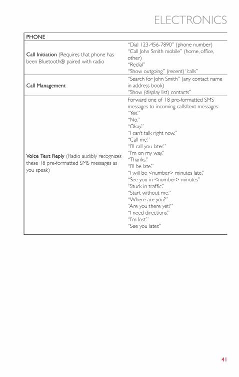
PHONE
Call Initiation (Requires that phone hasbeen Bluetooth® paired with radio
“Dial 123-456-7890” (phone number)“Call John Smith mobile” (home, office,other)“Redial”“Show outgoing” (recent) “calls”
Call Management“Search for John Smith” (any contact namein address book)“Show (display list) contacts”
Voice Text Reply (Radio audibly recognizesthese 18 pre-formatted SMS messages asyou speak)
Forward one of 18 pre-formatted SMSmessages to incoming calls/text messages:“Yes.”“No.”“Okay.”“I can’t talk right now.”“Call me.”“I’ll call you later.”“I’m on my way.”“Thanks.”“I’ll be late.”“I will be <number> minutes late.”“See you in <number> minutes”“Stuck in traffic.”“Start without me.”“Where are you?”“Are you there yet?”“I need directions.”“I’m lost.”“See you later.”
ELECTRONICS
41
Uconnect® 6.5N
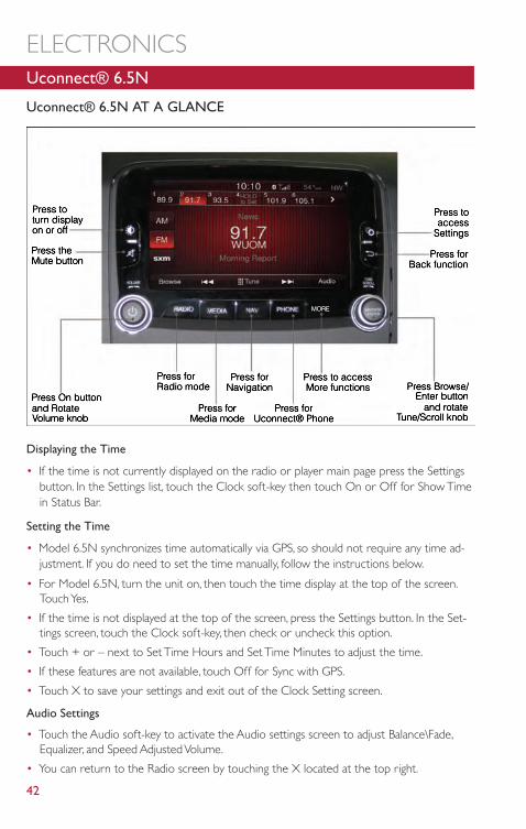
Uconnect® 6.5N AT A GLANCE
Displaying the Time
• If the time is not currently displayed on the radio or player main page press the Settingsbutton. In the Settings list, touch the Clock soft-key then touch On or Off for Show Timein Status Bar.
Setting the Time
• Model 6.5N synchronizes time automatically via GPS, so should not require any time ad-justment. If you do need to set the time manually, follow the instructions below.
• For Model 6.5N, turn the unit on, then touch the time display at the top of the screen.Touch Yes.
• If the time is not displayed at the top of the screen, press the Settings button. In the Set-tings screen, touch the Clock soft-key, then check or uncheck this option.
• Touch + or – next to Set Time Hours and Set Time Minutes to adjust the time.
• If these features are not available, touch Off for Sync with GPS.
• Touch X to save your settings and exit out of the Clock Setting screen.
Audio Settings
• Touch the Audio soft-key to activate the Audio settings screen to adjust Balance\Fade,Equalizer, and Speed Adjusted Volume.
• You can return to the Radio screen by touching the X located at the top right.
ELECTRONICS
42
Balance/Fade
• Touch the Balance/Fade soft-key to Balance audio between the front speakers or fade theaudio between the rear and front speakers.
• Touching the Front, Rear, Left, or Right soft-keys or touch and drag the Speaker Icon toadjust the Balance/Fade.
Equalizer
• Touch the Equalizer soft-key to activate the Equalizer screen.
• Touch the + or - soft-keys, or touch and drag over the level bar for each of the equalizerbands.The level value, which spans between plus or minus 9, is displayed at the bottom ofeach of the Bands.
Speed Adjusted Volume
• Touch the Speed Adjusted Volume soft-key to activate the Speed Adjusted Volume screen.The Speed Adjusted Volume is adjusted by touching the + and - buttons or by touchingand dragging over the level bar.This alters the automatic adjustment of the audio volumewith variation to vehicle speed.
Surround Sound
• Touch the Surround Sound soft-key, select On or Off followed by pressing the arrowback soft-key.When this feature is activated, it provides simulated surround sound mode.
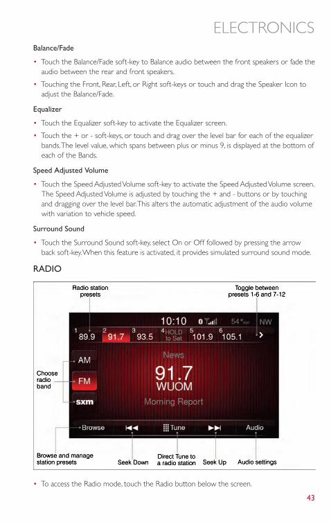
RADIO
• To access the Radio mode, touch the Radio button below the screen.
ELECTRONICS
43
Selecting Radio Stations
• Touch the desired radio band (AM, FM or SXM) soft-key.
Seek Up/Seek Down
• Touch the Seek arrow soft-keys for less than two seconds to seek through radio stations.
• Touch and hold either arrow soft-key for more than two seconds to bypass stations with-out stopping.The radio will stop at the next listenable station once the arrow soft-key isreleased.
Direct Tune
• Tune directly to a radio station by pressing the “Tune” button on the screen, and enteringthe desired station number.
Store Radio Presets
• Your radio can store 36 total preset stations, 12 presets per band (AM, FM and SXM).They are shown at the top of your radio screen.To see the 12 preset stations per band,press the arrow soft-key at the top right of the screen to toggle between the two sets ofsix presets.
• To set a station into memory press and hold the desired numbered soft-key for morethan two seconds or until you hear a confirmation beep.
SiriusXM PREMIER OVER 160 CHANNELS
• Get every channel available on your satellite radio, and enjoy all you want, all in one place.Hear commercial-free music plus sports, news, talk and entertainment. Get all the pre-mium programming, including Howard Stern, every NFL game, Oprah Radio®, everyMLB® and NHL® game, every NASCAR® race and more.And get 20+ Xtra channels,including SiriusXM Latino, a selection of channels dedicated to Spanish language program-ming.
• To access SiriusXM Satellite Radio, touch the SXM soft-key on the main Radio screen.
• The following describes features that are available when in SiriusXM Satellite Radio mode.
Seek Up/Seek Down
• Touch the Seek arrow soft-keys for less than two seconds to seek through channels inSXM mode.
• Touch and hold either arrow soft-key for more than two seconds to bypass channelswithout stopping.The radio will stop at the next listenable channel once the arrow soft-key is released.
Direct Tune
• Tune directly to a SXM channel by pressing the Tune soft-key on the screen, and enteringthe desired station number.
Traffic & Weather
• Automatically tells you when Traffic & Weather for a favorite city is available, and gives youthe option to switch to that channel.
ELECTRONICS
44
Fav
• Activates the favorites menu.You can add up to 50 favorite artists or songs. Just touchAdd Fav Artist or Add Fav Song while the song is playing.You will then be alerted anytime one of these songs, or works by these artists, is playing on other SiriusXM channels.
SiriusXM Parental Controls
• You can skip or hide certain channels from view if you do not want access to them.Touchthe Settings hard-key, touch the SiriusXM Setup soft-key, then select Channel Skip.Touchthe box, check-mark, next to the channel you want skipped.They will not show up in nor-mal usage.
• SiriusXM also offers the option to permanently block selected channels. Call(1-888-601-6297 for U.S. customers, 1-877-438-9677 for Canadian customers) and re-quest the Family-Friendly Package.
Browse
• Lets you browse the SiriusXM channel listing or Genre listing. Favorites, Game Zone,Weather and Jump settings also provide a way to browse the SiriusXM channel list.
BrowseSub-Menu
Sub-Menu Description
All Shows the channel listing.Genre Provides a list of all genres, and lets you jump to a channel within the selected
genre.Presets Lets you scroll the list of Preset satellite channels.Touch the channel,or press Enter
on theTune knob,to go to that channel.Touch the trash can icon to delete a preset.Your presets are also shown at the top of the main Satellite Radio screen.
Favorites Lets you manage artists and songs in the Favorites list and configureAlert Settingsto let you know when favorite songs or artists are playing on other channels.Also,view a list of channels airing any of your Favorites.
Game Zone Provides alerts when your favorite sports teams are starting a game which is beingaired on other SiriusXM channels,or when their game score is announced.You canselect and manage your Teams list here, and configure alerts.
Jump Lets you select your favorite cities forTraffic &Weather information,which is usedby the Jump feature on the main satellite radio screen.
ELECTRONICS
45
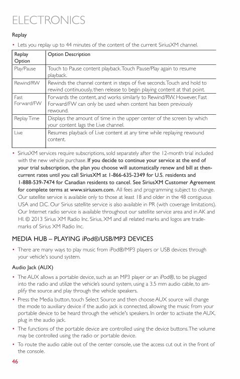
Replay
• Lets you replay up to 44 minutes of the content of the current SiriusXM channel.
ReplayOption
Option Description
Play/Pause Touch to Pause content playback.Touch Pause/Play again to resumeplayback.
Rewind/RW Rewinds the channel content in steps of five seconds.Touch and hold torewind continuously, then release to begin playing content at that point.
FastForward/FW
Forwards the content, and works similarly to Rewind/RW. However, FastForward/FW can only be used when content has been previouslyrewound.
Replay Time Displays the amount of time in the upper center of the screen by whichyour content lags the Live channel.
Live Resumes playback of Live content at any time while replaying rewoundcontent.
• SiriusXM services require subscriptions, sold separately after the 12-month trial includedwith the new vehicle purchase. If you decide to continue your service at the end ofyour trial subscription, the plan you choose will automatically renew and bill at then-current rates until you call SiriusXM at 1-866-635-2349 for U.S. residents and1-888-539-7474 for Canadian residents to cancel. See SiriusXM Customer Agreementfor complete terms at www.siriusxm.com. All fees and programming subject to change.Our satellite service is available only to those at least 18 and older in the 48 contiguousUSA and D.C. Our Sirius satellite service is also available in PR (with coverage limitations).Our Internet radio service is available throughout our satellite service area and in AK andHI. © 2013 Sirius XM Radio Inc. Sirius, XM and all related marks and logos are trade-marks of Sirius XM Radio Inc.
MEDIA HUB – PLAYING iPod®/USB/MP3 DEVICES
• There are many ways to play music from iPod®/MP3 players or USB devices throughyour vehicle's sound system.
Audio Jack (AUX)
• The AUX allows a portable device, such as an MP3 player or an iPod®, to be pluggedinto the radio and utilize the vehicle’s sound system, using a 3.5 mm audio cable, to am-plify the source and play through the vehicle speakers.
• Press the Media button, touch Select Source and then choose AUX source will changethe mode to auxiliary device if the audio jack is connected, allowing the music from yourportable device to be heard through the vehicle's speakers. In order to activate the AUX,plug in the audio jack.
• The functions of the portable device are controlled using the device buttons.The volumemay be controlled using the radio or portable device.
• To route the audio cable out of the center console, use the access cut out in the front ofthe console.
ELECTRONICS
46
USB Port
• Connect your iPod® or compatible device using a USB cable into the USB Port. USBMemory sticks with audio files can also be used.Then, audio from the device can beplayed on the vehicles sound system while providing metadata (artist, track title, album,etc.) information on the radio display.
• When connected, the iPod®/compatible USB device can be controlled using the radio orSteering Wheel Audio Controls to play, skip to the next or previous track, browse, and listthe contents.
• The iPod® battery charges when plugged into the USB port (if supported by the specificdevice).
• To route the USB/iPod® cable out of the center console, use the access cut out.
NOTE:
• When connecting your iPod® device for the first time, the system may take several min-utes to read your music, depending on the number of files. For example, the system willtake approximately five minutes for every 1000 songs loaded on the device.Also duringthe reading process, the Shuffle and Browse functions will be disabled.This process isneeded to ensure the full use of your iPod® features and only happens the first time it isconnected.After the first time, the reading process of your iPod® will take considerablyless time unless changes are made or new songs are added to the playlist.
• The USB port supports certain Mini, Classic, Nano,Touch, and iPhone® devices.The USBport also supports playing music from compatible external USB Mass Storage Classmemory devices. Some iPod® software versions may not fully support the USB portfeatures. Please visit Apple’s website for iPod® software updates.
SD Card
• Play songs stored on an SD card inserted into the SD card slot.
• Song playback can be controlled using the radio or Steering Wheel Audio Controls toplay, skip to the next or previous track, browse, and list the contents.
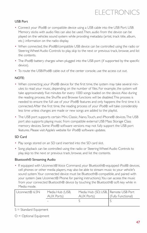
Bluetooth® Streaming Audio
• If equipped with Uconnect® Voice Command, your Bluetooth®-equipped iPod® devices,cell phones or other media players, may also be able to stream music to your vehicle'ssound system.Your connected device must be Bluetooth®-compatible, and paired withyour system (see Uconnect® Phone for pairing instructions).You can access the musicfrom your connected Bluetooth® device by touching the Bluetooth® soft-key while inMedia mode.
Uconnect® 6.5N Media Hub (USB,AUX Ports)
Media Hub (SD, USB,AUX Ports)
Remote USB Port(Fully Functional)
- S S
S = Standard Equipment
O = Optional Equipment
ELECTRONICS
47
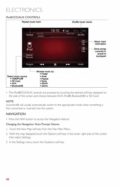
iPod®/CD/AUX CONTROLS
• The iPod®/CD/AUX controls are accessed by touching the desired soft-key displayed onthe side of the screen and choose between AUX, iPod®, Bluetooth® or SD Card.
NOTE:Uconnect® will usually automatically switch to the appropriate mode when something isfirst connected or inserted into the system.
NAVIGATION
• Press the NAV button to access the Navigation feature.
Changing the Navigation Voice Prompt Volume
1. Touch the View Map soft-key from the Nav Main Menu.
2. With the map displayed, touch the Options soft-key in the lower right area of the screenthen select Settings.
3. In the Settings menu, touch the Guidance soft-key.
ELECTRONICS
48
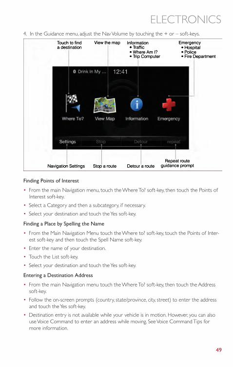
4. In the Guidance menu, adjust the Nav Volume by touching the + or – soft-keys.
Finding Points of Interest
• From the main Navigation menu, touch the Where To? soft-key, then touch the Points ofInterest soft-key.
• Select a Category and then a subcategory, if necessary.
• Select your destination and touch the Yes soft-key.
Finding a Place by Spelling the Name
• From the Main Navigation Menu touch the Where to? soft-key, touch the Points of Inter-est soft-key and then touch the Spell Name soft-key.
• Enter the name of your destination.
• Touch the List soft-key.
• Select your destination and touch the Yes soft-key.
Entering a Destination Address
• From the main Navigation menu touch the Where To? soft-key, then touch the Addresssoft-key.
• Follow the on-screen prompts (country, state/province, city, street) to enter the addressand touch the Yes soft-key.
• Destination entry is not available while your vehicle is in motion. However, you can alsouse Voice Command to enter an address while moving. See Voice Command Tips formore information.
ELECTRONICS
49
Setting Your Home Location
• Press the NAV button to access the Navigation system and the Main Navigation menu.
• Touch the Where To? soft-key, then touch the Go Home soft-key.
• You may enter your address directly, use your current location as your home address, orchoose from recently found locations.
• To delete your Home location (or other saved locations) so you can save a new Homelocation, touch the Where To? soft-key from the Main Navigation menu, then touch theGo Home soft-key, and in the Yes screen touch the Options soft-key. In the Optionsmenu touch Clear Home. Set a new Home location by following the previousinstructions.
Go Home
• A Home location must be saved in the system. From the Main Navigation menu, touchthe Where To? soft-key, then touch the Go Home soft-key.
• Your route is marked with a blue line on the map. If you depart from the original route,your route is recalculated.A speed limit icon could appear as you travel on majorroadways.
Adding a Stop
• To add a stop you must be navigating a route.
• Touch the Menu soft-key to return to the Main Navigation menu.
• Touch the Where To? soft-key, then search for the extra stop.When another location hasbeen selected, you can choose to cancel your previous route, add as the first destinationor add as the last destination.
ELECTRONICS
50
• Touch the desired selection and touch the Yes soft-key.
Taking a Detour
• To take a detour you must be navigating a route.
• Touch the Detour soft-key.
NOTE:If the route you are currently taking is the only reasonable option, the device might not cal-culate a detour.
• For more information, see your Uconnect® 6.5N Owner’s Manual Supplement.
Uconnect® Phone (Bluetooth® HANDS FREE CALLING)
• If the Uconnect® Phone Button exists on your steering wheel, then you have theUconnect® Phone features.
• The Uconnect® Phone is a voice-activated, hands-free, in-vehicle communications systemwith Voice Command Capability (see Voice Command section).
• The Uconnect® Phone allows you to dial a phone number with your mobile phone usingsimple voice commands or using screen soft-keys.
• Refer to the Understand The Features Of Your Vehicle section of your vehicle's Owner'sManual on the DVD for further details.
NOTE:The Uconnect® Phone requires a mobile phone equipped with the Bluetooth® Hands-Free Profile,Version 1.0 or higher. For Uconnect® Customer Support: U.S. residents visitwww.UconnectPhone.com or call 1-888-242-6342. Canadian Residents visitwww.UconnectPhone.com or call 1-800-465–2001 (English) or 1-800-387-9983 (French).
Pairing a Phone
• To use the Uconnect® Phone feature, you must first pair your Bluetooth® phone withthe Uconnect® system.
Start pairing procedure on the radio
• Press the Phone button and then the Settings soft-key. Next, touch Add Device.
• Uconnect® Phone will display an “In progress” screen while the system is connecting.
Start pairing procedure on mobile phone
• Search for available devices on your Bluetooth® enabled mobile phone.This is usuallywithin Settings or Options under “Bluetooth”. See your mobile phone’s manual for details.
• When your phone finds the system, select “Uconnect” as the paired device.You may beprompted by your phone to download the phonebook.This is so you can make calls bysaying the name of your contact (PBAP-Phone Book Access Profile).
ELECTRONICS
51
Complete the pairing procedure
• When prompted on the phone, verify with radio password shown on the Uconnect®Screen.
• If your phone asks you to accept a connection request from Uconnect, select “Yes”. Ifavailable, check the box telling it not to ask again – that way your phone will automaticallyconnect each time you start the vehicle.
Select the mobile phone's priority level
• When the pairing process has successfully completed, the system will prompt you tochoose whether or not this is your favorite phone. Selecting Yes will make this phone thehighest priority.This phone will take precedence over other paired phones within range.Only one phone can be paired at a time.
• You are now ready to make hands-free calls. Press the Uconnect® Phone button on yoursteering wheel to begin.
Making A Phone Call
• Press the Uconnect® Phone button .
• After the BEEP, say “dial” then the number (or “call” then the name as listed in yourphone; see Phonebook).
NOTE:You can also initiate a call by using the touch-screen on the Phone main screen.
Receiving A Call – Accept (And End)
• When an incoming call rings/is announced on Uconnect®, press thePhone button .
• To end a call, press the Hang Up or Phone button .
Mute (Or Unmute) Microphone During Call
• During a call, touch the mute soft-key on the Phone main screen to mute and unmutethe microphone.
Transfer Ongoing Call Between Handset And Vehicle
• During an on-going call, touch the Transfer soft-key on the Phone main screen to transferan on-going call between handset and vehicle.
Common Phone Commands (Examples)
• “Call John Smith”
• “Call John Smith mobile”
• “Dial 1 248 555 1212
• “Call Emergency”
• “Call Towing Assistance”
• “Redial”
ELECTRONICS
52
Phonebook
• Uconnect® radios will automatically download your phonebook from your paired phone,if this feature is supported by your phone. Entries are updated each time that the phoneis connected. If your phone book entries do not appear, check the settings on yourphone. Some phones require you to enable this feature manually.
• Your phonebook can be browsed on your radio screen, but editing can only be done onyour phone.To browse, touch the Phone soft-key, then the Phonebook soft-key.
• Favorite phonebook entries can be saved as Favorites for quicker access. Favorites areshown at the top of your main phone screen.
Voice Command Tips
• Using complete names (i.e; Call John Doe vs. Call John) will result in greater system accu-racy.
• You can “chain” commands together for faster results. Say “Call John Doe, mobile”, forexample.
• If you are listening to available voice command options, you do not have to listen to theentire list.When you hear the command that you need, press the button on thesteering wheel, wait for the beep and say your command.
Changing The Volume
• Start a dialogue by pressing the Phone button , then say a command for example -"Help".
• Use the radio ON/OFF VOLUME rotary knob to adjust the volume to a comfortablelevel while the Uconnect® system is speaking. Please note the volume setting forUconnect® is different than the audio system.
NOTE:To access help, press the Uconnect® Phone button on the steering wheel and say"help." Touch the display or push either or button and say "cancel" to cancelthe help session.
Voice Text Reply
• Uconnect® Phone can read or send new text messages on your mobile phone.
• Your mobile phone must be MAP (Message Access Profile) compatible to support SMSvia Bluetooth® to use this feature. If the Uconnect® Phone determines your phone isnot compatible with SMS messaging over Bluetooth® the “Messaging” button will begreyed out and the feature will not be available for use.
NOTE:For mobile phone compatibility and pairing instructions, please visitwww.UconnectPhone.com
ELECTRONICS
53
WARNING!
• Any voice commanded system should be used only in safe driving conditions follow-ing applicable laws regarding phone use.Your attention should be focused on safelyoperating the vehicle. Failure to do so may result in a collision causing you and othersto be severely injured or killed.
• In an emergency, to use Uconnect® Phone, your mobile phone must be:• turned on,• paired to Uconnect® Phone,• and have network coverage.
Uconnect® 6.5N Voice Command Quick Reference
If the Uconnect® Voice Command button exists on your steering wheel, you havethe Voice Command feature, which is optimized for the driver.The Voice Command featurelets you keep your hands on the wheel, and your eyes on the road.
When you press the Voice Command button located on the steering wheel, you willhear a beep.After the beep, give your command. If you do not know what commands tosay, you can say “help” and the system will provide options to you. If you ever wish to inter-rupt the system while it lists options, press the Voice Command button, after thebeep, say your command.
NOTE:All phone oriented voice commands are accessible by first pressing the Phone Pick Up
button, not the Voice Command button.To end a call, simply press the Phone Hang Upbutton. In some vehicles, the Phone Pickup button serves the dual purpose of
ending calls as well.
Voice Command (VR) User TIPs
• To hear available commands, press the Uconnect® Voice Command button and say“Help”.You will hear available commands for the menu displayed.
• At any time, you can say the words “Cancel” or “Help”.These commands are universaland can be used from virtually any menu.All other specific commands can be used de-pending upon the active application.
• You can interrupt the system prompts at any time by pressing the Uconnect® VoiceCommand button while the system is speaking.After the beep, you can say a command.
• You can ‘chain’ commands together for faster results. Say “Call Joe Doe mobile”, for ex-ample.
• For best performance, adjust the rearview mirror to provide at least ½ in (1 cm) gapbetween the overhead console (if equipped) and the mirror.This will create an unob-structed path to the microphone on the overhead console.
• Always wait for the beep before speaking.
ELECTRONICS
54
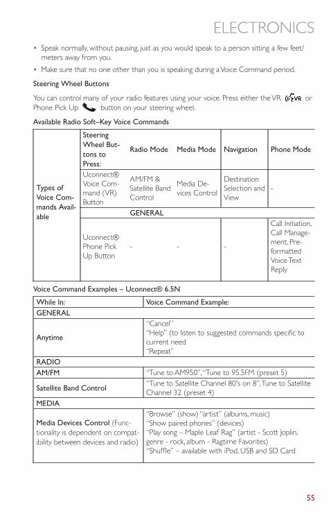
• Speak normally, without pausing, just as you would speak to a person sitting a few feet/meters away from you.
• Make sure that no one other than you is speaking during a Voice Command period.
Steering Wheel Buttons
You can control many of your radio features using your voice. Press either the VR orPhone Pick Up button on your steering wheel.
Available Radio Soft–Key Voice Commands
Types ofVoice Com-mands Avail-able
SteeringWheel But-tons toPress:
Radio Mode Media Mode Navigation Phone Mode
Uconnect®Voice Com-mand (VR)Button
AM/FM &Satellite BandControl
Media De-vices Control
DestinationSelection andView
-
GENERAL
Uconnect®Phone PickUp Button
- - -
Call Initiation,Call Manage-ment, Pre-formattedVoice TextReply
Voice Command Examples – Uconnect® 6.5N
While In: Voice Command Example:GENERAL
Anytime
“Cancel”“Help” (to listen to suggested commands specific tocurrent need“Repeat”
RADIOAM/FM “Tune to AM950”,“Tune to 95.5FM (preset 5)
Satellite Band Control“Tune to Satellite Channel 80's on 8”,Tune to SatelliteChannel 32 (preset 4)
MEDIA
Media Devices Control (Func-tionality is dependent on compat-ibility between devices and radio)
“Browse” (show) “artist” (albums, music)“Show paired phones” (devices)“Play song – Maple Leaf Rag” (artist - Scott Joplin,genre - rock, album - Ragtime Favorites)“Shuffle” – available with iPod, USB and SD Card
ELECTRONICS
55
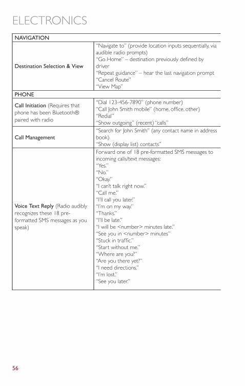
NAVIGATION
Destination Selection & View
“Navigate to” (provide location inputs sequentially, viaaudible radio prompts)“Go Home” – destination previously defined bydriver“Repeat guidance” – hear the last navigation prompt“Cancel Route”“View Map”
PHONE
Call Initiation (Requires thatphone has been Bluetooth®paired with radio
“Dial 123-456-7890” (phone number)“Call John Smith mobile” (home, office, other)“Redial”“Show outgoing” (recent) “calls”
Call Management“Search for John Smith” (any contact name in addressbook)“Show (display list) contacts”
Voice Text Reply (Radio audiblyrecognizes these 18 pre-formatted SMS messages as youspeak)
Forward one of 18 pre-formatted SMS messages toincoming calls/text messages:“Yes.”“No.”“Okay.”“I can’t talk right now.”“Call me.”“I’ll call you later.”“I’m on my way.”“Thanks.”“I’ll be late.”“I will be <number> minutes late.”“See you in <number> minutes”“Stuck in traffic.”“Start without me.”“Where are you?”“Are you there yet?”“I need directions.”“I’m lost.”“See you later.”
ELECTRONICS
56
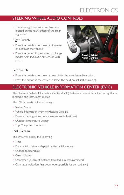
STEERING WHEEL AUDIO CONTROLS
• The steering wheel audio controls arelocated on the rear surface of the steer-ing wheel.
Right Switch
• Press the switch up or down to increaseor decrease the volume.
• Press the button in the center to changemodes AM/FM/CD/SXM/AUX or USBport.
Left Switch
• Press the switch up or down to search for the next listenable station.
• Press the button in the center to select the next preset station (radio).
ELECTRONIC VEHICLE INFORMATION CENTER (EVIC)The Electronic Vehicle Information Center (EVIC) features a driver-interactive display that islocated in the instrument cluster.
The EVIC consists of the following:
• System Status
• Vehicle Information Warning Message Displays
• Personal Settings (Customer-Programmable Features)
• Outside Temperature Display
• Trip Computer Functions
EVIC Screen
The EVIC will display the following:
• Time
• Date or trip distance display in miles or kilometers
• Outside temperature
• Gear Indicator
• Odometer (display of distance travelled in miles/kilometers)
• Car status indication (e.g. doors open, possible ice on road, etc.)
ELECTRONICS
57
EVIC Control Buttons
The EVIC control buttons are located on the instrument panel below the radio.
Press the MENU button briefly to access the menu and/or go to next screen or to confirmthe required menu option. Press and hold the MENU button (approximately one second)to return to the main screen.
Press the UP button to scroll upward through the displayed menu and the relatedoptions or to increase the displayed value.
Press the DOWN button to scroll downward through the displayed menu and therelated options or to decrease the value displayed.
NOTE:UP and DOWN buttons activate different functions according to the followingsituations:
• To scroll the menu options upwards or downwards.
• To increase or decrease values during settings.
NOTE:When opening one of the front doors, the EVIC display will turn on the clock and the milesor kilometers covered (for versions/markets, where provided) for a few seconds.
PROGRAMMABLE FEATURES
Uconnect® Customer Programmable Features - If Equipped
• The Uconnect® system allows you to access Customer Programmable feature settingssuch as Display, Clock, Safety/Assistance, Lights, Doors & Locks, Engine Off Operation,Compass Settings,Audio, Phone/Bluetooth,Auto-On Comfort and SiriusXM Setupthrough soft-keys.
• Press the More hard-key located below the display, then touch the Settings soft-key toaccess the Settings screen.When making a selection, scroll up or down until the preferredsetting is highlighted, then press and release the preferred setting until a check-mark ap-pears next to the setting, showing that setting has been selected.The following featuresettings are available:
• Display • Clock• Safety / Assistance • Doors & Locks• Compass • Engine Off Options• Phone / Bluetooth • Audio• Lights • SiriusXM Setup• Auto-On Comfort
ELECTRONICS
58
UNIVERSAL GARAGE DOOR OPENER (HomeLink®)• HomeLink® replaces up to three hand-held transmitters that operate devices such as
garage door openers, motorized gates, lighting or home security systems.TheHomeLink® unit is powered by your vehicles 12 Volt battery.
• The HomeLink® buttons that are located in the sunvisor designate the three differentHomeLink® channels.
• The HomeLink® indicator is located above the center button.
Before You Begin Programming HomeLink®
• Ensure that your vehicle is parked outside of the garage before you begin programming.
• For efficient programming and accurate transmission of the radio-frequency signal, it isrecommended that a new battery be placed in the hand-held transmitter of the devicethat is being programmed to the HomeLink® system.
• Erase all channels before you begin programming.To erase the channels, place the ignitionswitch into the ON/RUN position, then press and hold the two outside HomeLink®buttons (I and III) for up to 20 seconds or until the red indicator flashes.
NOTE:Erasing all channels should only be performed when programming HomeLink® for the firsttime. Do not erase channels when programming additional buttons.
• If you have any problems, or require assistance, please call toll-free 1–800–355–3515 or,on the Internet at www.HomeLink.com for information or assistance.
Programming A Rolling Code
• For programming Garage Door Openers that were manufactured after 1995.TheseGarage Door Openers can be identified by the “LEARN” or “TRAIN” button locatedwhere the hanging antenna is attached to the Garage Door Opener. It is NOT the buttonthat is normally used to open and close the door.The name and color of the button mayvary by manufacturer.
• Place the ignition switch into the ON/RUN position.
• Place the hand-held transmitter 1 to 3 in (3 to 8 cm) away from the HomeLink® buttonyou wish to program while keeping the HomeLink® indicator light in view.
• Simultaneously press and hold both the HomeLink® button you want to program andthe hand-held transmitter button.
• Continue to hold both buttons and observe the indicator light.The HomeLink® indicatorwill flash slowly and then rapidly after HomeLink® has received the frequency signalfrom the hand-held transmitter. Release both buttons after the indicator light changesfrom slow to rapid.
• At the garage door opener motor (in the garage), locate the “LEARN” or “TRAINING”button.This can usually be found where the hanging antenna wire is attached to the ga-rage door opener motor. Firmly press and release the “LEARN” or “TRAINING” button.
ELECTRONICS
59
NOTE:You have 30 seconds in which to initiate the next step after the LEARN button has beenpressed.
• Return to the vehicle and press the programmed HomeLink® button twice (holding thebutton for two seconds each time). If the device is plugged in and activates, programmingis complete.
NOTE:If the device does not activate, press the button a third time (for two seconds) to completethe training.
• To program the remaining two HomeLink® buttons, repeat each step for each remainingbutton. DO NOT erase the channels.
Programming A Non-Rolling Code
• For programming Garage Door Openers manufactured before 1995.
• Turn the ignition switch to the ON/RUN position.
• Place the hand-held transmitter 1 to 3 in (3 to 8 cm) away from the HomeLink® buttonyou wish to program while keeping the HomeLink® indicator light in view.
• Simultaneously press and hold both the HomeLink® button you want to program andthe hand-held transmitter button.
• Continue to hold both buttons and observe the indicator light.The HomeLink® indicatorwill flash slowly and then rapidly after HomeLink® has received the frequency signalfrom the hand-held transmitter. Release both buttons after the indicator light changesfrom slow to rapid.
• Press and hold the programmed HomeLink® button and observe the indicator light.
NOTE:
• If the indicator light stays on constantly, programming is complete and the garage door(or device) should activate when the HomeLink® button is pressed.
• To program the two remaining HomeLink® buttons, repeat each step for each re-maining button. DO NOT erase the channels.
Using HomeLink®
• To operate, press and release the programmed HomeLink® button.Activation will nowoccur for the programmed device (i.e., garage door opener, gate operator, security sys-tem, entry door lock, home/office lighting, etc.,).The hand-held transmitter of the devicemay also be used at any time.
ELECTRONICS
60
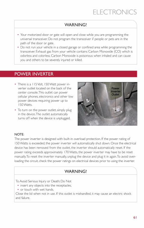
WARNING!
• Your motorized door or gate will open and close while you are programming theuniversal transceiver. Do not program the transceiver if people or pets are in thepath of the door or gate.
• Do not run your vehicle in a closed garage or confined area while programming thetransceiver. Exhaust gas from your vehicle contains Carbon Monoxide (CO) which isodorless and colorless. Carbon Monoxide is poisonous when inhaled and can causeyou and others to be severely injured or killed.
POWER INVERTER
• There is a 115 Volt, 150 Watt power in-verter outlet located on the back of thecenter console.This outlet can powercellular phones, electronics and other lowpower devices requiring power up to150 Watts.
• To turn on the power outlet, simply plugin the device.The outlet automaticallyturns off when the device is unplugged.
NOTE:The power inverter is designed with built-in overload protection. If the power rating of150 Watts is exceeded, the power inverter will automatically shut down. Once the electricaldevice has been removed from the outlet, the inverter should automatically reset. If thepower rating exceeds approximately 170 Watts, the power inverter may have to be resetmanually.To reset the inverter manually, unplug the device and plug it in again.To avoid over-loading the circuit, check the power ratings on electrical devices prior to using the inverter.
WARNING!
To Avoid Serious Injury or Death: Do Not• insert any objects into the receptacles,• or touch with wet hands.
Close the lid when not in use. If this outlet is mishandled, it may cause an electric shockand failure.
ELECTRONICS
61
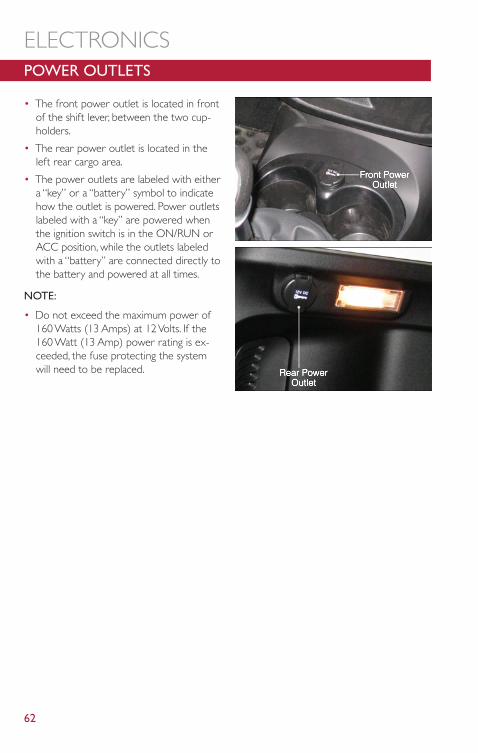
POWER OUTLETS
• The front power outlet is located in frontof the shift lever, between the two cup-holders.
• The rear power outlet is located in theleft rear cargo area.
• The power outlets are labeled with eithera “key” or a “battery” symbol to indicatehow the outlet is powered. Power outletslabeled with a “key” are powered whenthe ignition switch is in the ON/RUN orACC position, while the outlets labeledwith a “battery” are connected directly tothe battery and powered at all times.
NOTE:
• Do not exceed the maximum power of160 Watts (13 Amps) at 12 Volts. If the160 Watt (13 Amp) power rating is ex-ceeded, the fuse protecting the systemwill need to be replaced.
ELECTRONICS
62
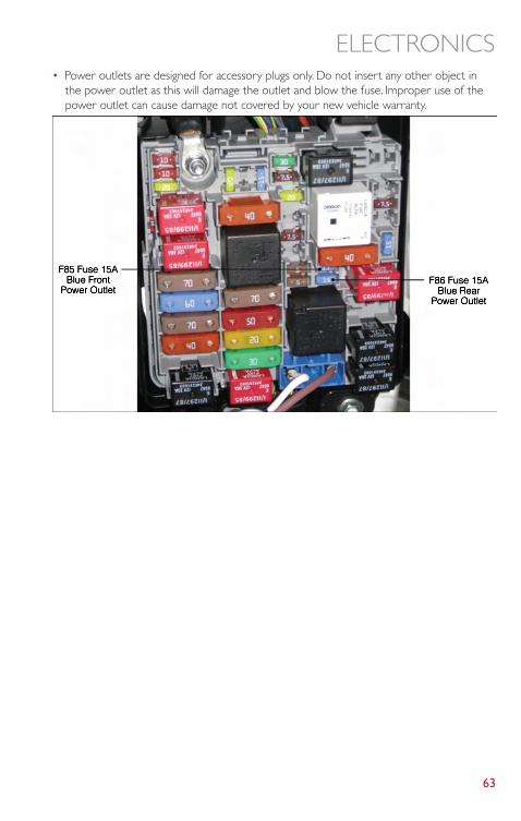
• Power outlets are designed for accessory plugs only. Do not insert any other object inthe power outlet as this will damage the outlet and blow the fuse. Improper use of thepower outlet can cause damage not covered by your new vehicle warranty.
ELECTRONICS
63
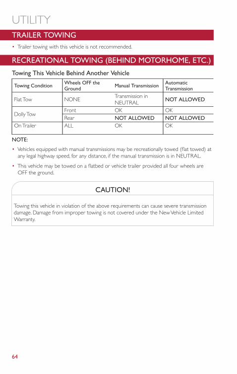
TRAILER TOWING• Trailer towing with this vehicle is not recommended.
RECREATIONAL TOWING (BEHIND MOTORHOME, ETC.)
Towing This Vehicle Behind Another Vehicle
Towing Condition Wheels OFF theGround Manual Transmission Automatic
Transmission
Flat Tow NONETransmission inNEUTRAL NOT ALLOWED
Dolly TowFront OK OKRear NOT ALLOWED NOT ALLOWED
On Trailer ALL OK OK
NOTE:
• Vehicles equipped with manual transmissions may be recreationally towed (flat towed) atany legal highway speed, for any distance, if the manual transmission is in NEUTRAL.
• This vehicle may be towed on a flatbed or vehicle trailer provided all four wheels areOFF the ground.
CAUTION!
Towing this vehicle in violation of the above requirements can cause severe transmissiondamage. Damage from improper towing is not covered under the New Vehicle LimitedWarranty.
UTILITY
64
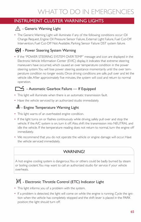
INSTRUMENT CLUSTER WARNING LIGHTS
- Generic Warning Light
• The Generic Warning Light will illuminate if any of the following conditions occur: OilChange Request, Engine Oil Pressure Sensor Failure, External Light Failure, Fuel Cut-OffIntervention, Fuel Cut-Off Not Available, Parking Sensor Failure DST system failure.
- Power Steering System Warning
• If the “POWER STEERING SYSTEM OVER TEMP” message and icon are displayed in theElectronic Vehicle Information Center (EVIC) display, it indicates that extreme steeringmaneuvers have occurred, which caused an over temperature condition in the powersteering system.You will lose power steering assistance momentarily until the over tem-perature condition no longer exists. Once driving conditions are safe, pull over and let thevehicle idle.After approximately five minutes, the system will cool and return to normaloperation.
- Automatic Gearbox Failure — If Equipped
• This light will illuminate when there is an automatic transmission fault.
• Have the vehicle serviced by an authorized studio immediately.
- Engine Temperature Warning Light
• This light warns of an overheated engine condition.
• If the light turns on or flashes continuously while driving, safely pull over and stop thevehicle. If the A/C system is on, turn it off.Also, shift the transmission into NEUTRAL andidle the vehicle. If the temperature reading does not return to normal, turn the engine offimmediately.
• We recommend that you do not operate the vehicle or engine damage will occur. Havethe vehicle serviced immediately.
WARNING!
A hot engine cooling system is dangerous.You or others could be badly burned by steamor boiling coolant.You may want to call an authorized studio for service if your vehicleoverheats.
- Electronic Throttle Control (ETC) Indicator Light
• This light informs you of a problem with the system.
• If a problem is detected, the light will come on while the engine is running. Cycle the igni-tion when the vehicle has completely stopped and the shift lever is placed in the PARKposition; the light should turn off.
WHAT TO DO IN EMERGENCIES
65
• If the light remains lit with the engine running, your vehicle will usually be drivable; how-ever, see an authorized studio immediately. If the light is flashing when the engine is run-ning, immediate service is required and you may experience reduced performance, anelevated/rough idle or engine stall and your vehicle may require towing.
- Electronic Stability Control (ESC) OFF Indicator Light
• This light indicates the ESC system has been turned off by the driver.
- Electronic Stability Control (ESC) Activation / MalfunctionIndicator Light
• The “ESC Activation/Malfunction Indicator Light” in the instrument cluster will come onfor four seconds when the ignition switch is turned to the ON/RUN position. If the “ESCActivation/Malfunction Indicator Light” comes on continuously with the engine running, amalfunction has been detected in the ESC system. If this light remains on, see your autho-rized studio as soon as possible to have the problem diagnosed and corrected.
NOTE:
• The “ESC Off Indicator Light” and the “ESC Activation/Malfunction Indicator Light” comeon momentarily each time the ignition switch is turned to ON/RUN.
• Each time the ignition is turned to ON/RUN, the ESC system will be ON even if it wasturned off previously.
• ESC Activation/Malfunction Light can blink during a ESC or TC intervention.
- Tire Pressure Monitoring System (TPMS) Light
• Each tire, including the spare (if provided), should be checked monthly, when cold andinflated to the inflation pressure recommended by the vehicle manufacturer on the ve-hicle placard or tire inflation pressure label. (If your vehicle has tires of a different sizethan the size indicated on the vehicle placard or tire inflation pressure label, you shoulddetermine the proper tire inflation pressure for those tires.)
• As an added safety feature, your vehicle has been equipped with a Tire Pressure Monitor-ing System (TPMS) that illuminates a low tire pressure telltale when one or more of yourtires is significantly under-inflated.Accordingly, when the low tire pressure telltale illumi-nates, you should stop and check your tires as soon as possible, and inflate them to theproper pressure. Driving on a significantly under-inflated tire causes the tire to overheatand can lead to tire failure. Under-inflation also reduces fuel efficiency and tire tread life,and may affect the vehicle’s handling and stopping ability.
• IF THE LIGHT STARTS FLASHING INDICATING A LOW TIRE PRESSURE, ADJUSTTHE AIR PRESSURE IN THE LOW TIRE TO THE AIR PRESSURE SHOWN ON THEVEHICLE PLACARD OR TIRE INFLATION PRESSURE LABEL LOCATED ON THEDRIVER'S DOOR.
NOTE:AFTER INFLATION,THE VEHICLE MAY NEED TO BE DRIVEN FOR 20 MINUTES BE-FORE THE FLASHING LIGHT WILL TURN OFF.
WHAT TO DO IN EMERGENCIES
66
• Please note that the TPMS is not a substitute for proper tire maintenance, and it is thedriver’s responsibility to maintain correct tire pressure, even if under-inflation has notreached the level to trigger illumination of the TPMS low tire pressure telltale.
• Your vehicle has also been equipped with a TPMS malfunction indicator to indicate whenthe system is not operating properly.The TPMS malfunction indicator is combined withthe low tire pressure telltale.When the system detects a malfunction, the telltale will flashfor approximately one minute and then remain continuously illuminated.This sequencewill continue each time the vehicle is restarted as long as the malfunction exists.
• When the malfunction indicator is illuminated, the system may not be able to detect orsignal low tire pressure as intended.TPMS malfunctions may occur for a variety of rea-sons, including the installation of replacement or alternate tires or wheels on the vehiclethat prevent the TPMS from functioning properly.Always check the TPMS malfunctiontelltale after replacing one or more tires or wheels on your vehicle, to ensure that thereplacement or alternate tires and wheels allow the TPMS to continue to functionproperly.
NOTE:Tire pressures change by approximately 1 psi (7 kPa) per 12° F (7° C) of air temperaturechange. Keep this in mind when checking tire pressure inside a garage, especially in the Win-ter. Example: If garage temperature is 68°F (20°C) and the outside temperature is 32°F(0°C), then the cold tire inflation pressure should be increased by 3 psi (21 kPa), whichequals 1 psi (7 kPa) for every 12°F (7°C) for this outside temperature condition.
CAUTION!
The TPMS has been optimized for the original equipment tires and wheels.TPMS pres-sures and warning have been established for the tire size equipped on your vehicle. Unde-sirable system operation or sensor damage may result when using replacement equip-ment that is not of the same size, type, and/or style.Aftermarket wheels can cause sensordamage. Do not use tire sealant from a can, or balance beads if your vehicle is equippedwith a TPMS, as damage to the sensors may result.
BRAKE - Brake Warning Light
• The Brake Warning light illuminates when there is either a system malfunction or theparking brake is applied. If the light is on and the parking brake is not applied, it indicates apossible brake hydraulic malfunction, brake booster problem or an Anti-Lock Brake Sys-tem problem.
• Please have your vehicle serviced immediately.
WHAT TO DO IN EMERGENCIES
67
WARNING!
Driving a vehicle with the red brake light on is dangerous. Part of the brake system mayhave failed. It will take longer to stop the vehicle.You could have a collision. Have the ve-hicle checked immediately.
- Malfunction Indicator Light (MIL)
• Certain conditions, such as a loose or missing gas cap, poor fuel quality, etc., may illuminatethe MIL after engine start.The vehicle should be serviced if the light stays on throughseveral typical driving cycles. In most situations, the vehicle will drive normally and notrequire towing.
• If the MIL flashes when the engine is running, serious conditions may exist that could leadto immediate loss of power or severe catalytic converter damage.We recommend youdo not operate the vehicle. Have the vehicle serviced immediately.
- Charging System Light
• This light shows the status of the electrical charging system. If the charging system lightremains on, it means that the vehicle is experiencing a problem with the charging system.
• We recommend you do not continue driving if the charging system light is on. Have thevehicle serviced immediately.
- Oil Pressure Warning Light
• This light indicates low engine oil pressure. If the light turns on while driving, stop the ve-hicle and shut off the engine as soon as possible.A chime will sound when this light turnson.
• We recommend you do not operate the vehicle or engine damage will occur. Have thevehicle serviced immediately.
- Anti-Lock Brake (ABS) Light
• This light monitors the Anti-Lock Brake System (ABS).
• If the light is not on during starting, stays on, or turns on while driving, we recommendyou drive to the nearest authorized studio immediately and have the vehicle servicedimmediately.
- Air Bag Warning Light
• If the light is not on during starting, stays on, or turns on while driving, have the vehicleserviced by an authorized studio immediately.
- Seat Belt Reminder Light
• When the ignition switch is first turned to ON/RUN, this light will turn on if the driver’sseat belt is unbuckled, a chime will sound.When driving, if the driver’s seat belt remainsunbuckled, the Seat Belt Reminder Light will illuminate and the chime will sound.
WHAT TO DO IN EMERGENCIES
68
• Please have your vehicle serviced immediately.
WARNING!
Driving a vehicle with the red brake light on is dangerous. Part of the brake system mayhave failed. It will take longer to stop the vehicle.You could have a collision. Have the ve-hicle checked immediately.
Passenger Air Bag Disable (PAD) Light
The Passenger Air Bag Disable (PAD) Indicator Light tells the driver and front passengerwhen the front passenger air bag is turned off.The PAD Indicator light illuminates thewords “PASS AIR BAG OFF” to show that the front passenger air bag will not inflate duringa collision requiring air bags.When the right front passenger seat is empty or when verylight objects are placed on the seat, the passenger air bag will not inflate even though thePAD indicator light is not illuminated.
IF YOUR ENGINE OVERHEATS• In any of the following situations, you can reduce the potential for overheating by taking
the appropriate action.• On the highways — slow down.• In city traffic — while stopped, shift transmission into NEUTRAL, but do not increase
engine idle speed.
NOTE:There are steps that you can take to slow down an overheat condition:
• If your air conditioner (A/C) is on, turn it off.The A/C system adds heat to the enginecooling system and turning the A/C off can help remove this heat.
• You can also turn the Temperature control to maximum heat, the Mode control to floorand the Fan control to high.This allows the heater core to act as a supplement to theradiator and aids in removing heat from the engine cooling system.
• If the temperature reading does not return to normal, turn the engine off immediately.
• We recommend that you do not operate the vehicle or engine damage will occur. Havethe vehicle serviced immediately.
CAUTION!
Driving with a hot cooling system could damage your vehicle. If the temperature gaugereads hot, pull over and stop the vehicle. Idle the vehicle with the air conditioner turnedoff until the pointer drops back into the normal range. If the pointer remains on hot, turnthe engine off immediately and call for service.
WHAT TO DO IN EMERGENCIES
69
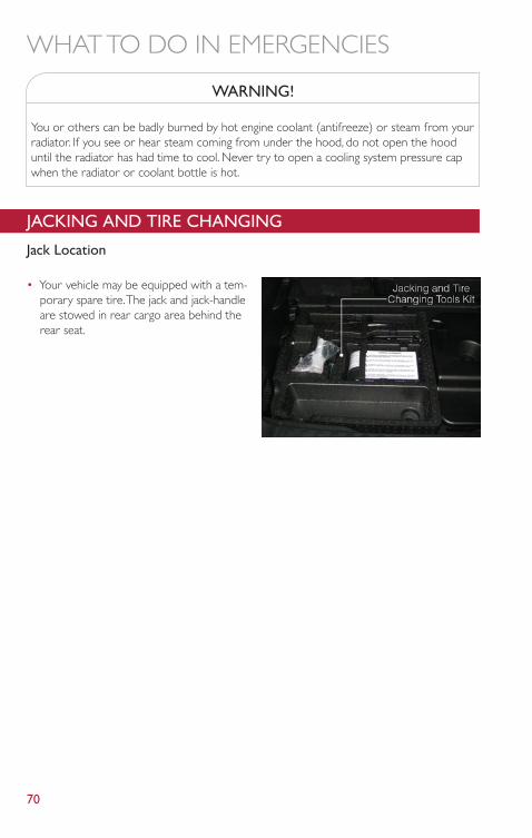
WARNING!
You or others can be badly burned by hot engine coolant (antifreeze) or steam from yourradiator. If you see or hear steam coming from under the hood, do not open the hooduntil the radiator has had time to cool. Never try to open a cooling system pressure capwhen the radiator or coolant bottle is hot.
JACKING AND TIRE CHANGING
Jack Location
• Your vehicle may be equipped with a tem-porary spare tire.The jack and jack-handleare stowed in rear cargo area behind therear seat.
WHAT TO DO IN EMERGENCIES
70
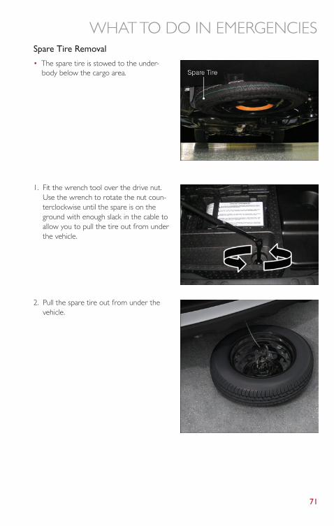
Spare Tire Removal
• The spare tire is stowed to the under-body below the cargo area.
1. Fit the wrench tool over the drive nut.Use the wrench to rotate the nut coun-terclockwise until the spare is on theground with enough slack in the cable toallow you to pull the tire out from underthe vehicle.
2. Pull the spare tire out from under thevehicle.
WHAT TO DO IN EMERGENCIES
71
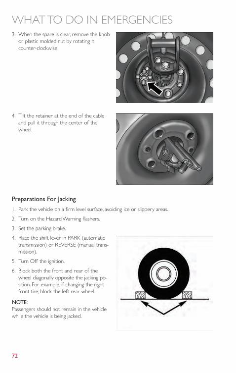
3. When the spare is clear, remove the knobor plastic molded nut by rotating itcounter-clockwise.
4. Tilt the retainer at the end of the cableand pull it through the center of thewheel.
Preparations For Jacking
1. Park the vehicle on a firm level surface, avoiding ice or slippery areas.
2. Turn on the Hazard Warning flashers.
3. Set the parking brake.
4. Place the shift lever in PARK (automatictransmission) or REVERSE (manual trans-mission).
5. Turn Off the ignition.
6. Block both the front and rear of thewheel diagonally opposite the jacking po-sition. For example, if changing the rightfront tire, block the left rear wheel.
NOTE:Passengers should not remain in the vehiclewhile the vehicle is being jacked.
WHAT TO DO IN EMERGENCIES
72
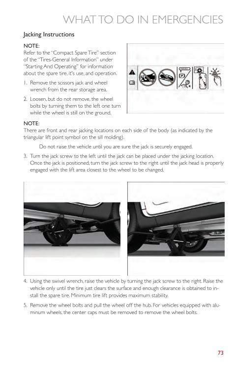
Jacking Instructions
NOTE:Refer to the “Compact Spare Tire” sectionof the “Tires-General Information” under“Starting And Operating” for informationabout the spare tire, it's use, and operation.
1. Remove the scissors jack and wheelwrench from the rear storage area.
2. Loosen, but do not remove, the wheelbolts by turning them to the left one turnwhile the wheel is still on the ground.
NOTE:There are front and rear jacking locations on each side of the body (as indicated by thetriangular lift point symbol on the sill molding).
Do not raise the vehicle until you are sure the jack is securely engaged.
3. Turn the jack screw to the left until the jack can be placed under the jacking location.Once the jack is positioned, turn the jack screw to the right until the jack head is properlyengaged with the lift area closest to the wheel to be changed.
4. Using the swivel wrench, raise the vehicle by turning the jack screw to the right. Raise thevehicle only until the tire just clears the surface and enough clearance is obtained to in-stall the spare tire. Minimum tire lift provides maximum stability.
5. Remove the wheel bolts and pull the wheel off the hub. For vehicles equipped with alu-minum wheels, the center caps must be removed to remove the wheel bolts.
WHAT TO DO IN EMERGENCIES
73
NOTE:The wheel cover is held on the wheel by the wheel bolts.When reinstalling the originalwheel, properly align the wheel cover to the valve stem, place the wheel cover onto thewheel, then install the wheel bolts.
6. Install the spare wheel and wheel bolts with the cone shaped end of the bolts towardthe wheel. Lightly tighten the bolts.To avoid the risk of forcing the vehicle off the jack, donot tighten the bolts fully until the vehicle has been lowered.
7. Lower the vehicle by turning the jack screw to the left.
8. Finish tightening the bolts. Push down on the wrench while tightening the wheel bolts.Alternate bolts until each bolt has been tightened twice.The correct wheel bolt torque is63 ft lbs (85 N·m) for steel wheels and 75 ft lbs (100 N·m) for aluminum wheels. If youdoubt that you have tightened the bolts correctly, have them checked with a torquewrench by your authorized studio or service station.
9. Disassemble the jack and tools and place them in the in the rear cargo area.
10. Place the deflated (flat) tire in the cargo area. Have the tire repaired or replaced assoon as possible.
11. Check the spare tire pressure as soon as possible. Correct the tire pressure as required.
Spare Tire Stowage
• Reverse instructions of the spare removal section.
• Rotate the jack wrench tool on the winch drive nut clockwise until effort becomes heavyand an audible click is heard indicating the spare is properly stowed.
CAUTION!
• The winch mechanism is designed for use with the jack extension tube only. Use ofan air wrench or other power tools is not recommended and they can damage thewinch.
• Do not attempt to raise the vehicle by jacking on locations other than those indi-cated in the Jacking Instructions for this vehicle.
• Be sure to mount the spare tire with the valve stem facing outward.The vehiclecould be damaged if the spare tire is mounted incorrectly.
WHAT TO DO IN EMERGENCIES
74
WARNING!
• Do not attempt to change a tire on the side of the vehicle close to moving traffic.Pull far enough off the road to avoid the danger of being hit when operating the jackor changing the wheel.
• Being under a jacked-up vehicle is dangerous.The vehicle could slip off the jack andfall on you.You could be crushed. Never put any part of your body under a vehiclethat is on a jack.
• Never start or run the engine while the vehicle is on a jack. if you need to get undera raised vehicle, take it to a authorized studio where it can be raised on a lift.
• The jack is designed to use as a tool for changing tires only.The jack should not beused to lift the vehicle for service purposes.The vehicle should be jacked on a firm,level surface only.Avoid ice or slippery areas.
• After using the jack and tools, always reinstall them in the original carrier and loca-tion.While driving you may experience abrupt stopping, rapid acceleration, or sharpturns.A loose jack, tools, bracket or other objects in the vehicle may move aroundwith force, resulting in serious injury.
• Carefully follow these tire changing warnings to help prevent personal injury or dam-age to your vehicle:
• Always park on a firm, level surface as far from the edge of the roadway as possiblebefore raising the vehicle.
• Turn on the Hazard Warning flasher.• Block the wheel diagonally opposite the wheel to be raised.• Set the parking brake firmly and set an automatic transmission in PARK; a manual
transmission in REVERSE.• Do not let anyone sit in the vehicle when it is on a jack.• Do not get under the vehicle when it is on a jack.• Only use the jack in the positions indicated and for lifting this vehicle during a tire
change.• If working on or near a roadway, be extremely careful of motor traffic.• To assure that spare tires, flat or inflated, are securely stowed, spares must be stowed
with the valve stem facing the ground.• Raising the vehicle higher than necessary can make the vehicle unstable and cause a
collision. It could slip off the jack and hurt someone near it. Raise the vehicle onlyenough to remove the tire.
• A loose tire or jack thrown forward in a collision or hard stop could injure someonein the vehicle.Always stow the jack parts and the extra tire and wheel in the placesprovided.
WHAT TO DO IN EMERGENCIES
75
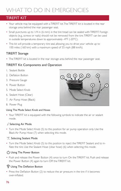
TIREFIT KIT• Your vehicle may be equipped with a TIREFIT kit.The TIREFIT kit is located in the rear
storage area behind the rear passenger seat.
• Small punctures up to 1/4 in (6 mm) in the tire tread can be sealed with TIREFIT. Foreignobjects (e.g., screws or nails) should not be removed from the tire.TIREFIT can be usedin outside temperatures down to approximately -4°F (-20°C).
• This kit will provide a temporary tire seal, allowing you to drive your vehicle up to100 miles (160 km) with a maximum speed of 55 mph (88 km/h).
TIREFIT Storage
• The TIREFIT kit is located in the rear storage area behind the rear passenger seat.
TIREFIT Kit Components and Operation
1. Sealant Bottle
2. Deflation Button
3. Pressure Gauge
4. Power Button
5. Mode Select Knob
6. Sealant Hose (Clear)
7. Air Pump Hose (Black)
8. Power Plug
Using The Mode Select Knob and Hoses
• Your TIREFIT kit is equipped with the following symbols to indicate the air or sealantmode.
Selecting Air Mode
• Turn the Mode Select Knob (5) to this position for air pump operation only. Use theBlack Air Pump Hose (7) when selecting this mode.
Selecting Sealant Mode
• Turn the Mode Select Knob (5) to this position to inject the TIREFIT Sealant and to in-flate the tire. Use the Sealant Hose (clear hose) (6) when selecting this mode.
Using The Power Button
• Push and release the Power Button (4) once to turn On the TIREFIT kit. Push and releasethe Power Button (4) again to turn Off the TIREFIT kit.
Using The Deflation Button
• Press the Deflation Button (2) to reduce the air pressure in the tire if it becomesover-inflated.
WHAT TO DO IN EMERGENCIES
76
TIREFIT Usage Precautions
• Replace the TIREFIT Sealant Bottle (1) and Sealant Hose (6) prior to the expiration date(printed on the bottle label) to assure optimum operation of the system. Refer to “Seal-ing a Tire with TIREFIT” section (F) “Sealant Bottle and Hose Replacement”.
• The Sealant Bottle (1) and Sealant Hose (6) are a one tire application use.After each use,always replace these components immediately at an authorized studio.
• When the TIREFIT sealant is in a liquid form, clean water, and a damp cloth will removethe material from the vehicle or tire and wheel components. Once the sealant dries, itcan easily be peeled off and properly discarded.
• For optimum performance, make sure the valve stem on the wheel is free of debris be-fore connecting the TIREFIT kit.
• You can use the TIREFIT air pump to inflate bicycle tires.The kit also comes with twoneedles, located in the Accessory Storage Compartment (on the bottom of the airpump) for inflating sport balls, rafts, or similar inflatable items. However, use only the AirPump Hose (7) and make sure the Mode Select Knob (5) is in the Air Mode when inflat-ing such items to avoid injecting sealant into them.The TIREFIT Sealant is only intended toseal punctures less than 1/4 in (6 mm) diameter in the tread of your vehicle.
• Do not lift or carry the TIREFIT kit by the hoses.
Sealing A Tire With TIREFIT
(A) Whenever You Stop To Use TIREFIT:
1. Pull over to a safe location and turn on the vehicle’s Hazard Warning flashers.
2. Verify that the valve stem (on the wheel with the deflated tire) is in a position that isnear to the ground.This will allow the TIREFIT Hoses (6) and (7) to reach the valve stemand keep the TIREFIT kit flat on the ground.This will provide the best positioning of thekit when injecting the sealant into the deflated tire and running the air pump. Move thevehicle as necessary to place the valve stem in this position before proceeding.
3. Place the transmission in PARK (auto transmission) or in Gear (manual transmission) andcycle the ignition to the OFF position.
4. Set the parking brake.
(B) Setting Up To Use TIREFIT:
1. Turn the Mode Select Knob (5) to the Sealant Mode position.
2. Uncoil the Sealant Hose (6) and then remove the cap from the fitting at the end of thehose.
3. Place the TIREFIT kit flat on the ground next to the deflated tire.
4. Remove the cap from the valve stem and then screw the fitting at the end of the SealantHose (6) onto the valve stem.
5. Uncoil the Power Plug (8) and insert the plug into the vehicle’s 12 Volt power outlet.
WHAT TO DO IN EMERGENCIES
77
6. Do not remove foreign objects (e.g., screws or nails) from the tire.
(C) Injecting TIREFIT Sealant Into The Deflated Tire:
• Always start the engine before turning ON the TIREFIT kit.
NOTE:Manual transmission vehicles must have the parking brake engaged and the shift lever inNEUTRAL.
• After pressing the Power Button (4), the sealant (white fluid) will flow from the SealantBottle (1) through the Sealant Hose (6) and into the tire.
NOTE:Sealant may leak out through the puncture in the tire.
• If the sealant (white fluid) does not flow within 0 – 10 seconds through the SealantHose (6):
1. Press the Power Button (4) to turn Off the TIREFIT kit. Disconnect the Sealant Hose (6)from the valve stem. Make sure the valve stem is free of debris. Reconnect the SealantHose (6) to the valve stem. Check that the Mode Select Knob (5) is in the Sealant Modeposition and not Air Mode. Press the Power Button (4) to turn On the TIREFIT kit.
2. Connect the Power Plug (8) to a different 12 Volt power outlet in your vehicle or an-other vehicle, if available. Make sure the engine is running before turning ON the TIREFITkit.
3. The Sealant Bottle (1) may be empty due to previous use. Call for assistance.
NOTE:If the Mode Select Knob (5) is on Air Mode and the pump is operating, air will dispensefrom the Air Pump Hose (7) only, not the Sealant Hose (6).
• If the sealant (white fluid) does flow through the Sealant Hose (6):
1. Continue to operate the pump until sealant is no longer flowing through the hose (typi-cally takes 30 - 70 seconds).As the sealant flows through the Sealant Hose (6), the Pres-sure Gauge (3) can read as high as 70 psi (5 kPa).The Pressure Gauge (3) will decreasequickly from approximately 70 psi (5 kPa) to the actual tire pressure when the SealantBottle (1) is empty.
2. The pump will start to inject air into the tire immediately after the Sealant Bottle (1) isempty. Continue to operate the pump and inflate the tire to the pressure indicated onthe tire pressure label on the driver-side latch pillar (recommended pressure). Check thetire pressure by looking at the Pressure Gauge (3).
• If the tire does not inflate to at least 26 psi (1.8 kPa) pressure within 15 minutes:• The tire is too badly damaged. Do not attempt to drive the vehicle further. Call for
assistance.
WHAT TO DO IN EMERGENCIES
78
NOTE:If the tire becomes over-inflated, press the Deflation Button to reduce the tire pressure tothe recommended inflation pressure before continuing.
• If the tire inflates to the recommended pressure or is at least 26 psi (1.8 Bar) pres-sure within 15 minutes:
1. Press the Power Button (4) to turn off the TIREFIT kit.
2. Remove the Speed Limit sticker from the top of the Sealant Bottle (1) and place thesticker on the instrument panel.
3. Immediately disconnect the Sealant Hose (6) from the valve stem, reinstall the cap onthe fitting at the end of the hose, and place the TIREFIT kit in the vehicle storage loca-tion. Quickly proceed to (D) “Drive Vehicle”.
(D) Drive Vehicle:
• Immediately after injecting sealant and inflating the tire, drive the vehicle 5 miles (8 km)or 10 minutes to ensure distribution of the TIREFIT Sealant within the tire. Do not ex-ceed 55 mph (88 km/h).
(E) After Driving:
• Pull over to a safe location. Refer to “Whenever You Stop to Use TIREFIT” beforecontinuing.
1. Turn the Mode Select Knob (5) to the Air Mode position.
2. Uncoil the Air Pump Hose (7) (black in color) and screw the fitting at the end of hose(7) onto the valve stem.
3. Uncoil the power plug and insert the plug into the vehicles 12 Volt power outlet.
4. Check the pressure in the tire by reading the Pressure Gauge (3).
• If tire pressure is less than 19 psi (1.3 kPa), the tire is too badly damaged. Do not at-tempt to drive the vehicle further. Call for assistance.
If the tire pressure is 19 psi (1.3 kPa) or higher:
1. Press the Power Button (4) to turn on TIREFIT and inflate the tire to the pressure indi-cated on the tire and loading information label on the driver-side door opening.
2. Disconnect the TIREFIT kit from the valve stem, reinstall the cap on the valve stem andunplug from 12 Volt outlet.
3. Place the TIREFIT kit in its proper storage area in the vehicle.
4. Have the tire inspected and repaired or replaced at the earliest opportunity at an autho-rized studio or tire service center.
5. Replace the Sealant Bottle (1) and Sealant Hose (6) assembly at your authorized studioas soon as possible. Refer to “(F) Sealant Bottle and Hose Replacement.”
WHAT TO DO IN EMERGENCIES
79
NOTE:
• If the tire becomes over-inflated, press the Deflation Button to reduce the tire pressureto the recommended inflation pressure before continuing.
• When having the tire serviced, advise the authorized studio or service center that thetire has been sealed using the TIREFIT service kit.
(F) Sealant Bottle And Hose Replacement:
1. Uncoil the Sealant Hose (6) (clear in color).
2. Locate the round Sealant Bottle release button in the recessed area under the sealantbottle.
3. Press the Sealant Bottle release button.The Sealant Bottle (1) will pop up. Remove thebottle and dispose of it accordingly.
4. Clean any remaining sealant from the TIREFIT housing.
5. Position the new Sealant Bottle (1) in the housing so that the Sealant Hose (6) alignswith the hose slot in the front of the housing. Press the bottle into the housing.An au-dible click will be heard indicating the bottle is locked into place.
6. Verify that the cap is installed on the fitting at the end of the Sealant Hose (6) and re-turn the hose to its storage area (located on the bottom of the air pump).
7. Return the TIREFIT kit to its storage location in the vehicle.
CAUTION!
• The metal end fitting from Power Plug (8) may get hot after use, so it should behandled carefully.
• Failure to reinstall the cap on the fitting at the end of the Sealant Hose (6) can resultin sealant contacting your skin, clothing, and the vehicle’s interior. It can also result insealant contacting internal TIREFIT kit components which may cause permanentdamage to the kit.
WHAT TO DO IN EMERGENCIES
80
WARNING!
• Do not attempt to seal a tire on the side of the vehicle closest to traffic. Pull farenough off the road to avoid the danger of being hit when using the TIREFIT kit.
• Do not use TIREFIT or drive the vehicle under the following circumstances:• If the puncture in the tire tread is approximately 1/4 in. (6 mm) or larger.• If the tire has any sidewall damage.• If the tire has any damage from driving with extremely low tire pressure.• If the tire has any damage from driving on a flat tire.• If the wheel has any damage.• If you are unsure of the condition of the tire or the wheel.
• Keep TIREFIT away from open flames or heat source.• A loose TIREFIT kit thrown forward in a collision or hard stop could endanger the
occupants of the vehicle.Always stow the TIREFIT kit in the place provided. Failure tofollow these warnings can result in injuries that are serious or fatal to you, your pas-sengers, and others around you.
• Take care not to allow the contents of TIREFIT to come in contact with hair, eyes, orclothing.TIREFIT is harmful if inhaled, swallowed, or absorbed through the skin. Itcauses skin, eye, and respiratory irritation. Flush immediately with plenty of water ifthere is any contact with eyes or skin. Change clothing as soon as possible, if there isany contact with clothing.
• TIREFIT Sealant solution contains latex. In case of an allergic reaction or rash, consulta physician immediately. Keep TIREFIT out of reach of children. If swallowed, rinsemouth immediately with plenty of water and drink plenty of water. Do not inducevomiting! Consult a physician immediately.
• TIREFIT is not a permanent flat tire repair. Have the tire inspected and repaired orreplaced after using TIREFIT. Do not exceed 55 mph (88 km/h) until the tire is re-paired or replaced. Failure to follow this warning can result in injuries that are seriousor fatal to you, your passengers, and others around you.
JUMP-STARTING PROCEDURE• If your vehicle has a discharged battery, it can be jump-started using a set of jumper
cables and a battery in another vehicle or by using a portable battery booster pack. Jump-starting can be dangerous if done improperly so please follow the procedures in this sec-tion carefully.
NOTE:When using a portable battery booster pack, follow the manufacturer’s operating instruc-tions and precautions.
WHAT TO DO IN EMERGENCIES
81
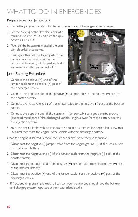
Preparations For Jump-Start
• The battery in your vehicle is located on the left side of the engine compartment.
1. Set the parking brake, shift the automatictransmission into PARK and turn the igni-tion to OFF/LOCK.
2. Turn off the heater, radio, and all unneces-sary electrical accessories.
3. If using another vehicle to jump-start thebattery, park the vehicle within thejumper cables reach, set the parking brakeand make sure the ignition is OFF.
Jump-Starting Procedure
1. Connect the positive (+) end of thejumper cable to the positive (+) post ofthe discharged vehicle.
2. Connect the opposite end of the positive (+) jumper cable to the positive (+) post ofthe booster battery.
3. Connect the negative end (-) of the jumper cable to the negative (-) post of the boosterbattery.
4. Connect the opposite end of the negative (-) jumper cable to a good engine ground(exposed metal part of the discharged vehicles engine) away from the battery and thefuel injection system.
5. Start the engine in the vehicle that has the booster battery, let the engine idle a few min-utes, and then start the engine in the vehicle with the discharged battery.
Once the engine is started, remove the jumper cables in the reverse sequence:
1. Disconnect the negative (-) jumper cable from the engine ground (-) of the vehicle withthe discharged battery.
2. Disconnect the negative end (-) of the jumper cable from the negative (-) post of thebooster battery.
3. Disconnect the opposite end of the positive (+) jumper cable from the positive (+) postof the booster battery.
4. Disconnect the positive (+) end of the jumper cable from the positive (+) post of thedischarged vehicle.
• If frequent jump-starting is required to start your vehicle, you should have the batteryand charging system inspected at your authorized studio.
WHAT TO DO IN EMERGENCIES
82
CAUTION!
• Accessories that can be plugged into the vehicle power outlets draw power fromthe vehicle’s battery, even when not in use (i.e., cellular phones, etc.). Eventually, ifplugged in long enough, the vehicle’s battery will discharge sufficiently to degradebattery life and/or prevent the engine from starting.
• Do not use a portable battery booster pack or any other booster source with asystem voltage greater than 12 Volts or damage to the battery, starter motor, alterna-tor or electrical system may occur.
• Failure to follow these procedures could result in damage to the charging system ofthe booster vehicle or the discharged vehicle.
WARNING!
• Do not attempt jump-starting if the battery is frozen. It could rupture or explodeand cause personal injury.
• Take care to avoid the radiator cooling fan whenever the hood is raised. It can startanytime the ignition switch is on.You can be injured by moving fan blades.
• Remove any metal jewelry such as watch bands or bracelets that might make an in-advertent electrical contact.You could be seriously injured.
• Batteries contain sulfuric acid that can burn your skin or eyes and generate hydrogengas which is flammable and explosive. Keep open flames or sparks away from thebattery.
• Do not allow vehicles to touch each other as this could establish a ground connec-tion and personal injury could result.
• Failure to follow this procedure could result in personal injury or property damagedue to battery explosion.
• Do not connect the cable to the negative post (-)of the discharged battery.The resulting electrical spark could cause the battery toexplode and could result in personal injury.
SHIFT LEVER OVERRIDE• If a malfunction occurs and the shift lever cannot be moved out of the PARK position,
you can use the following procedure to temporarily move the shift lever:• Turn the ignition switch to the OFF position.• Firmly set the parking brake.• Remove the rubber storage tray liner from the center console, then lift up the front of
the shift lever bezel, carefully disengage the bezel from the shift lever housing, and slideit up to the top of the shift lever.
• Press and maintain firm pressure on the brake pedal.
WHAT TO DO IN EMERGENCIES
83
• Insert a small screwdriver or similar tool down into the access slot at the front of theshift lever assembly, and push and hold the white override release lever down.
• Move the shift lever into the NEUTRAL position.• The vehicle may then be started in NEUTRAL.• Reinstall the shift lever bezel (use care to avoid pinching the wiring), and the rubber
storage tray liner.
TOWING A DISABLED VEHICLE
With Ignition Key
Automatic Transmission
• Vehicle can be towed with the front wheels elevated.
• Vehicle can be towed on a flatbed truck (all wheels off the ground).
Manual Transmission
• Vehicle can be flat towed (all four wheels on the ground) with the transmission in NEU-TRAL.
• Vehicle can be towed with the front wheels elevated.
• Vehicle can be towed on a flatbed truck (all wheels off the ground).
NOTE:If it is necessary to use the accessories while being towed (wipers, defrosters, etc.), the keymust be in the ON/RUN position. Make certain the transmission remains in NEUTRAL.
All Transmissions
• If it is necessary to use the accessories while being towed (wipers, defrosters, etc.), thekey must be in the ON/RUN position. Make certain the transmission remains inNEUTRAL.
Without The Ignition Key
• Special care must be taken when the vehicle is towed with the ignition in the OFF/LOCKposition.A dolly should be used under the front wheels if the rear wheels are raised.Proper towing equipment is necessary to prevent damage to the vehicle.
• Battery power is required to release the brake/transmission interlock system (automatictransmission only).There is a removable plug in the right side of the shift lever housingthat allows you to insert your finger to override the system.The ignition key must be inthe ON/RUN position to use the override lever.
WHAT TO DO IN EMERGENCIES
84
CAUTION!
• Failure to follow these towing methods can cause severe transmission damage. Suchdamage is not covered by the New Vehicle Limited Warranty.
• DO NOT flat tow any vehicle equipped with an automatic transmission. Damage tothe drivetrain will result.
• If the vehicle being towed requires steering, the ignition switch must be in the ON/RUN position.
• Do not attempt to use sling-type equipment when towing.When securing the ve-hicle to a flatbed truck, do not attach to front or rear suspension components. Dam-age to your vehicle may result from improper towing.
FREEING A STUCK VEHICLE• If your vehicle becomes stuck in mud, sand or snow, it can often be moved by a rocking
motion.Turn your steering wheel right and left to clear the area around the front wheels.Then shift back and forth between DRIVE/1st gear and REVERSE. Using minimal accel-erator pedal pressure to maintain the rocking motion, without spinning the wheels, ismost effective.
NOTE:If your vehicle is equipped with Traction Control or Electronic Stability Control (ESC), turnthe system OFF before attempting to “rock” the vehicle.
CAUTION!
• Racing the engine or spinning the wheels may lead to transmission overheating andfailure.Allow the engine to idle with the shift lever in NEUTRAL for at least oneminute after every five rocking-motion cycles.This will minimize overheating andreduce the risk of transmission failure during prolonged efforts to free a stuck ve-hicle.
• When “rocking” a stuck vehicle by moving between DRIVE/2nd and REVERSE, donot spin the wheels faster than 15 mph (24 km/h), or drivetrain damage may result.
• Revving the engine or spinning the wheels too fast may lead to transmission over-heating and failure. It can also damage the tires. Do not spin the wheels above30 mph (48 km/h) while in gear (no transmission shifting occurring).
WHAT TO DO IN EMERGENCIES
85
WARNING!
Fast spinning tires can be dangerous. Forces generated by excessive wheel speeds maycause damage, or even failure, of the axle and tires.A tire could explode and injure some-one. Do not spin your vehicle's wheels faster than 30 mph (48 km/h) or for longer than30 seconds continuously without stopping when you are stuck and do not let anyone neara spinning wheel, no matter what the speed.
CAP-LESS FUEL FILL FUNNEL• The funnel for the Cap-Less Fuel System is located in the rear cargo area behind the rear
seat. If your vehicle is out of fuel and an auxiliary fuel can is needed, insert the funnel intothe filler neck and proceed to fill the vehicle.
• For more information on the Cap-Less Fuel Fill Funnel refer to “Adding Fuel” in “Operat-ing Your Vehicle” in this manual.
WHAT TO DO IN EMERGENCIES
86
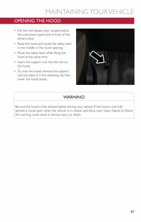
OPENING THE HOOD
• Pull the red release lever located belowthe instrument panel and in front of thedriver’s door.
• Raise the hood and locate the safety latchin the middle of the hood opening.
• Move the safety latch while lifting thehood at the same time.
• Insert the support rod into the slot onthe hood.
• To close the hood, remove the supportrod and place it in the retaining clip, thenlower the hood slowly.
WARNING!
Be sure the hood is fully latched before driving your vehicle. If the hood is not fullylatched, it could open when the vehicle is in motion and block your vision. Failure to followthis warning could result in serious injury or death.
MAINTAINING YOUR VEHICLE
87
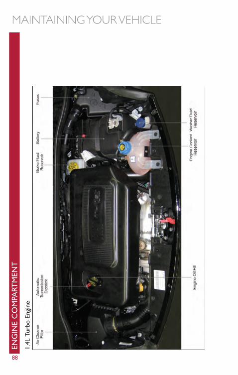
ENG
INE
CO
MPA
RTM
ENT
1.4L
Turb
oEn
gine
MAINTAINING YOUR VEHICLE
88
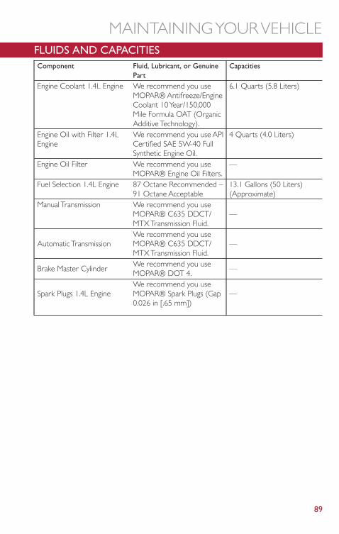
FLUIDS AND CAPACITIESComponent Fluid, Lubricant, or Genuine
PartCapacities
Engine Coolant 1.4L Engine We recommend you useMOPAR® Antifreeze/EngineCoolant 10 Year/150,000Mile Formula OAT (OrganicAdditive Technology).
6.1 Quarts (5.8 Liters)
Engine Oil with Filter 1.4LEngine
We recommend you use APICertified SAE 5W-40 FullSynthetic Engine Oil.
4 Quarts (4.0 Liters)
Engine Oil Filter We recommend you useMOPAR® Engine Oil Filters.
—
Fuel Selection 1.4L Engine 87 Octane Recommended –91 Octane Acceptable
13.1 Gallons (50 Liters)(Approximate)
Manual Transmission We recommend you useMOPAR® C635 DDCT/MTX Transmission Fluid.
—
Automatic TransmissionWe recommend you useMOPAR® C635 DDCT/MTX Transmission Fluid.
—
Brake Master CylinderWe recommend you useMOPAR® DOT 4.
—
Spark Plugs 1.4L EngineWe recommend you useMOPAR® Spark Plugs (Gap0.026 in [.65 mm])
—
MAINTAINING YOUR VEHICLE
89
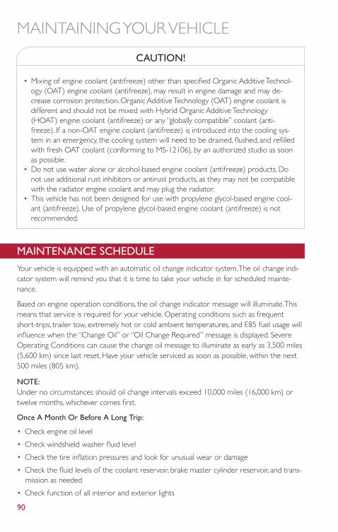
CAUTION!
• Mixing of engine coolant (antifreeze) other than specified Organic Additive Technol-ogy (OAT) engine coolant (antifreeze), may result in engine damage and may de-crease corrosion protection. Organic Additive Technology (OAT) engine coolant isdifferent and should not be mixed with Hybrid Organic Additive Technology(HOAT) engine coolant (antifreeze) or any “globally compatible” coolant (anti-freeze). If a non-OAT engine coolant (antifreeze) is introduced into the cooling sys-tem in an emergency, the cooling system will need to be drained, flushed, and refilledwith fresh OAT coolant (conforming to MS-12106), by an authorized studio as soonas possible.
• Do not use water alone or alcohol-based engine coolant (antifreeze) products. Donot use additional rust inhibitors or antirust products, as they may not be compatiblewith the radiator engine coolant and may plug the radiator.
• This vehicle has not been designed for use with propylene glycol-based engine cool-ant (antifreeze). Use of propylene glycol-based engine coolant (antifreeze) is notrecommended.
MAINTENANCE SCHEDULEYour vehicle is equipped with an automatic oil change indicator system.The oil change indi-cator system will remind you that it is time to take your vehicle in for scheduled mainte-nance.
Based on engine operation conditions, the oil change indicator message will illuminate.Thismeans that service is required for your vehicle. Operating conditions such as frequentshort-trips, trailer tow, extremely hot or cold ambient temperatures, and E85 fuel usage willinfluence when the “Change Oil” or “Oil Change Required” message is displayed. SevereOperating Conditions can cause the change oil message to illuminate as early as 3,500 miles(5,600 km) since last reset. Have your vehicle serviced as soon as possible, within the next500 miles (805 km).
NOTE:Under no circumstances should oil change intervals exceed 10,000 miles (16,000 km) ortwelve months, whichever comes first.
Once A Month Or Before A Long Trip:
• Check engine oil level
• Check windshield washer fluid level
• Check the tire inflation pressures and look for unusual wear or damage
• Check the fluid levels of the coolant reservoir, brake master cylinder reservoir, and trans-mission as needed
• Check function of all interior and exterior lights
MAINTAINING YOUR VEHICLE
90
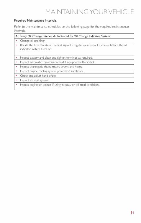
Required Maintenance Intervals.
Refer to the maintenance schedules on the following page for the required maintenanceintervals.
At Every Oil Change Interval As Indicated By Oil Change Indicator System:• Change oil and filter.• Rotate the tires. Rotate at the first sign of irregular wear, even if it occurs before the oil
indicator system turns on.
• Inspect battery and clean and tighten terminals as required.• Inspect automatic transmission fluid if equipped with dipstick.• Inspect brake pads, shoes, rotors, drums, and hoses.• Inspect engine cooling system protection and hoses.• Check and adjust hand brake.• Inspect exhaust system.• Inspect engine air cleaner if using in dusty or off-road conditions.
MAINTAINING YOUR VEHICLE
91
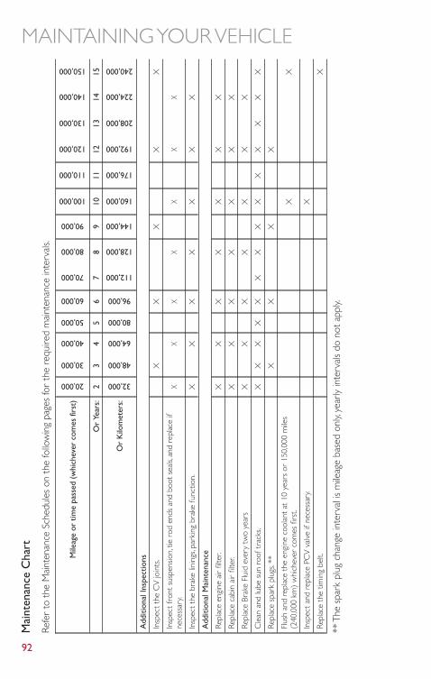
Mai
nten
ance
Cha
rt
Refe
rto
the
Mai
nten
ance
Sche
dule
son
the
follo
win
gpa
ges
for
the
requ
ired
mai
nten
ance
inte
rval
s.
Mile
age
ortim
epa
ssed
(whi
chev
erco
mes
first
)
20,000
30,000
40,000
50,000
60,000
70,000
80,000
90,000
100,000
110,000
120,000
130,000
140,000
150,000
Or
Year
s:2
34
56
78
910
1112
1314
15
Or
Kilo
met
ers:
32,000
48,000
64,000
80,000
96,000
112,000
128,000
144,000
160,000
176,000
192,000
208,000
224,000
240,000
Add
ition
alIn
spec
tions
Insp
ectt
heC
Vjo
ints
.X
XX
XX
Insp
ectf
ront
susp
ensio
n,tie
rod
ends
and
boot
seal
s,an
dre
plac
eif
nece
ssar
y.X
XX
XX
XX
Insp
ectt
hebr
ake
linin
gs,p
arki
ngbr
ake
func
tion.
XX
XX
XX
X
Add
ition
alM
aint
enan
ce
Repl
ace
engi
neai
rfil
ter.
XX
XX
XX
X
Repl
ace
cabi
nai
rfil
ter.
XX
XX
XX
X
Repl
ace
Brak
eFl
uid
ever
ytw
oye
ars
XX
XX
XX
X
Cle
anan
dlu
besu
nro
oftr
acks
.X
XX
XX
XX
XX
XX
XX
X
Repl
ace
spar
kpl
ugs.
**X
XX
X
Flus
han
dre
plac
eth
een
gine
cool
anta
t10
year
sor
150,
000
mile
s(2
40,0
00km
)w
hich
ever
com
esfir
st.
XX
Insp
ecta
ndre
plac
ePC
Vva
lve
ifne
cess
ary.
X
Repl
ace
the
timin
gbe
lt.X
**Th
esp
ark
plug
chan
gein
terv
alis
mile
age
base
don
ly,ye
arly
inte
rval
sdo
nota
pply.
MAINTAINING YOUR VEHICLE
92
WA
RN
ING
!
•Yo
uca
nbe
badl
yin
jure
dw
orki
ngon
orar
ound
am
otor
vehi
cle.
Do
only
serv
ice
wor
kfo
rw
hich
you
have
the
know
ledg
ean
dth
erig
hteq
uipm
ent.
Ifyo
uha
vean
ydo
ubta
bout
your
abilit
yto
perf
orm
ase
rvic
ejo
b,ta
keyo
urve
hicl
eto
aco
mpe
tent
mec
hani
c.•
Failu
reto
prop
erly
insp
ecta
ndm
aint
ain
your
vehi
cle
coul
dre
sult
ina
com
pone
ntm
alfu
nctio
nan
def
fect
vehi
cle
hand
ling
and
perf
or-
man
ce.T
his
coul
dca
use
anac
cide
nt.
MAINTAINING YOUR VEHICLE
93
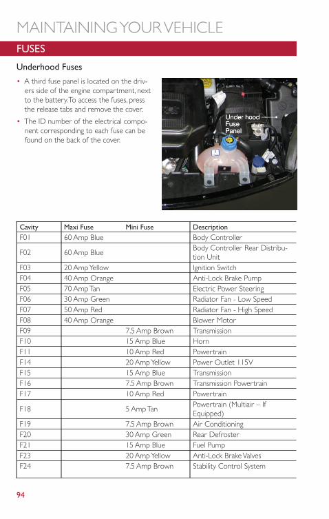
FUSES
Underhood Fuses
• A third fuse panel is located on the driv-ers side of the engine compartment, nextto the battery.To access the fuses, pressthe release tabs and remove the cover.
• The ID number of the electrical compo-nent corresponding to each fuse can befound on the back of the cover.
Cavity Maxi Fuse Mini Fuse DescriptionF01 60 Amp Blue Body Controller
F02 60 Amp BlueBody Controller Rear Distribu-tion Unit
F03 20 Amp Yellow Ignition SwitchF04 40 Amp Orange Anti-Lock Brake PumpF05 70 Amp Tan Electric Power SteeringF06 30 Amp Green Radiator Fan - Low SpeedF07 50 Amp Red Radiator Fan - High SpeedF08 40 Amp Orange Blower MotorF09 7.5 Amp Brown TransmissionF10 15 Amp Blue HornF11 10 Amp Red PowertrainF14 20 Amp Yellow Power Outlet 115VF15 15 Amp Blue TransmissionF16 7.5 Amp Brown Transmission PowertrainF17 10 Amp Red Powertrain
F18 5 Amp TanPowertrain (Multiair – IfEquipped)
F19 7.5 Amp Brown Air ConditioningF20 30 Amp Green Rear DefrosterF21 15 Amp Blue Fuel PumpF23 20 Amp Yellow Anti-Lock Brake ValvesF24 7.5 Amp Brown Stability Control System
MAINTAINING YOUR VEHICLE
94
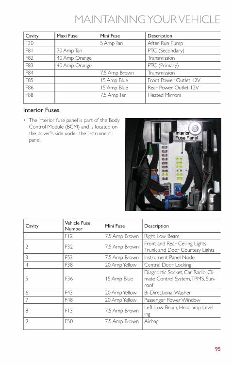
Cavity Maxi Fuse Mini Fuse DescriptionF30 5 Amp Tan After Run PumpF81 70 Amp Tan PTC (Secondary)F82 40 Amp Orange TransmissionF83 40 Amp Orange PTC (Primary)F84 7.5 Amp Brown TransmissionF85 15 Amp Blue Front Power Outlet 12VF86 15 Amp Blue Rear Power Outlet 12VF88 7.5 Amp Tan Heated Mirrors
Interior Fuses
• The interior fuse panel is part of the BodyControl Module (BCM) and is located onthe driver's side under the instrumentpanel.
Cavity Vehicle FuseNumber Mini Fuse Description
1 F12 7.5 Amp Brown Right Low Beam
2 F32 7.5 Amp BrownFront and Rear Ceiling LightsTrunk and Door Courtesy Lights
3 F53 7.5 Amp Brown Instrument Panel Node4 F38 20 Amp Yellow Central Door Locking
5 F36 15 Amp BlueDiagnostic Socket, Car Radio, Cli-mate Control System,TPMS, Sun-roof
6 F43 20 Amp Yellow Bi-Directional Washer7 F48 20 Amp Yellow Passenger Power Window
8 F13 7.5 Amp BrownLeft Low Beam, Headlamp Level-ing
9 F50 7.5 Amp Brown Airbag
MAINTAINING YOUR VEHICLE
95
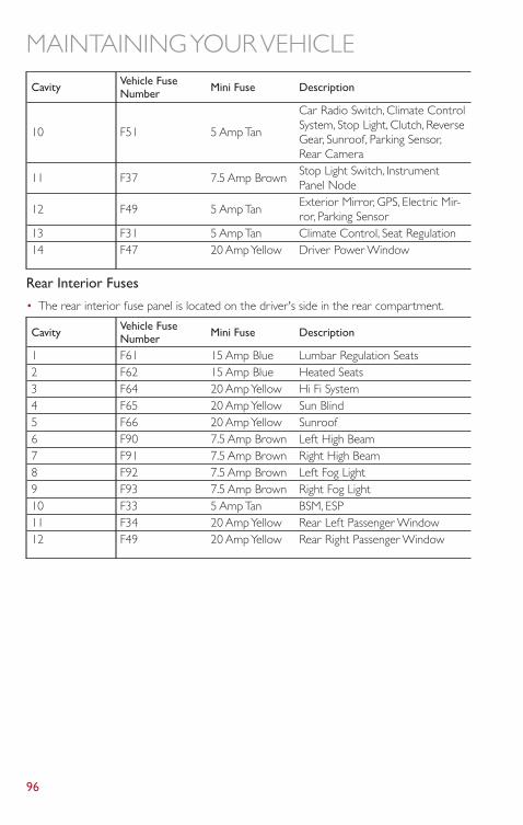
Cavity Vehicle FuseNumber Mini Fuse Description
10 F51 5 Amp Tan
Car Radio Switch, Climate ControlSystem, Stop Light, Clutch, ReverseGear, Sunroof, Parking Sensor,Rear Camera
11 F37 7.5 Amp BrownStop Light Switch, InstrumentPanel Node
12 F49 5 Amp TanExterior Mirror, GPS, Electric Mir-ror, Parking Sensor
13 F31 5 Amp Tan Climate Control, Seat Regulation14 F47 20 Amp Yellow Driver Power Window
Rear Interior Fuses
• The rear interior fuse panel is located on the driver's side in the rear compartment.
Cavity Vehicle FuseNumber Mini Fuse Description
1 F61 15 Amp Blue Lumbar Regulation Seats2 F62 15 Amp Blue Heated Seats3 F64 20 Amp Yellow Hi Fi System4 F65 20 Amp Yellow Sun Blind5 F66 20 Amp Yellow Sunroof6 F90 7.5 Amp Brown Left High Beam7 F91 7.5 Amp Brown Right High Beam8 F92 7.5 Amp Brown Left Fog Light9 F93 7.5 Amp Brown Right Fog Light10 F33 5 Amp Tan BSM, ESP11 F34 20 Amp Yellow Rear Left Passenger Window12 F49 20 Amp Yellow Rear Right Passenger Window
MAINTAINING YOUR VEHICLE
96
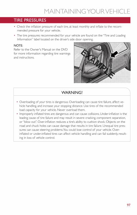
TIRE PRESSURES• Check the inflation pressure of each tire, at least monthly and inflate to the recom-
mended pressure for your vehicle.
• The tire pressures recommended for your vehicle are found on the “Tire and LoadingInformation” label located on the driver’s side door opening.
NOTE:Refer to the Owner's Manual on the DVDfor more information regarding tire warningsand instructions.
WARNING!
• Overloading of your tires is dangerous. Overloading can cause tire failure, affect ve-hicle handling, and increase your stopping distance. Use tires of the recommendedload capacity for your vehicle. Never overload them.
• Improperly inflated tires are dangerous and can cause collisions. Under-inflation is theleading cause of tire failure and may result in severe cracking, component separation,or “blow out”. Over-inflation reduces a tire’s ability to cushion shock. Objects on theroad and chuck holes can cause damage that results in tire failure. Unequal tire pres-sures can cause steering problems.You could lose control of your vehicle. Over-inflated or under-inflated tires can affect vehicle handling and can fail suddenly, result-ing in loss of vehicle control.
MAINTAINING YOUR VEHICLE
97
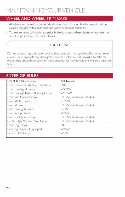
WHEEL AND WHEEL TRIM CARE• All wheels and wheel trim, especially aluminum and chrome plated wheels, should be
cleaned regularly with a mild soap and water to prevent corrosion.
• To remove heavy soil and/or excessive brake dust, use a wheel cleaner or equivalent orselect a non-abrasive, non-acidic cleaner.
CAUTION!
Do not use scouring pads, steel wool, a bristle brush, or metal polishes. Do not use ovencleaner.These products may damage the wheel's protective finish.Avoid automatic carwashes that use acidic solutions or harsh brushes that may damage the wheel's protectivefinish.
EXTERIOR BULBSLIGHT BULBS – Exterior Bulb NumberFront Low and High Beam Headlamp HIR2LLFront Turn Signal Lamps WY21WFront Parking/Daytime Running Lamps W21/5WFront Side Marker Lamps LED (See Authorized studio)Rear Tail/Stop Lamps P21/5WRear Tail Lamp LED (See Authorized studio)Rear Turn Signal Lamps P21WRear Backup Lamps W16WRear Side Marker Lamps LED (See Authorized studio)Center High Mounted Stop Lamp LED (See Authorized studio)Front Fog Lamps H11Rear Fog Lamps - If Equipped W16WLicense Plate Lamps W5W
MAINTAINING YOUR VEHICLE
98
FIAT CUSTOMER CENTER
P.O. Box 21–8004
Auburn Hills, MI 48321–8004
Phone: 1-888-242-6342
ASSISTANCE FOR THE HEARING IMPAIRED• To assist customers who have hearing difficulties, the manufacturer has installed special
TDD (Telecommunication Devices for the Deaf) equipment at its customer center.Anyhearing or speech impaired customer, who has access to a TDD or a conventional tele-typewriter (TTY) in the United States, can communicate with the manufacturer by dialing1–800–380–CHRY. Canadian residents with hearing difficulties that require assistance canuse the special needs relay service offered by Bell Canada. For TTY teletypewriter users,dial 711 and for Voice callers, dial 1–800–855–0511 to connect with a Bell Relay Serviceoperator.
WARNING!
Engine exhaust, some of its constituents, and certain vehicle components contain, or emit,chemicals known to the State of California to cause cancer and birth defects, or otherreproductive harm. In addition, certain fluids contained in vehicles and certain products ofcomponent wear contain, or emit, chemicals known to the State of California to causecancer and birth defects, or other reproductive harm.
PUBLICATIONS ORDERING• If you are the first registered retail owner of your vehicle, you may obtain one free
printed copy of the Owner's Manual,Warranty Booklet or Radio Manuals on your DVDby calling 1–888–242–6342 (U.S.) or 1–800–387–1143 (Canada) or by contacting yourstudio.
• Replacement English User Guide kits or DVDs may be purchased by visiting www.techau-thority.com or by calling 1–800–890–4038 (U.S.) or 1–800–387–1143 (Canada).Visa,Master Card,American Express and Discover orders are accepted. If you prefer mailingyour order, please call the above numbers for an order form.
NOTE:A street address is required when ordering manuals (no P.O. Boxes).
CONSUMER ASSISTANCE
99

REPORTING SAFETY DEFECTS IN THE UNITED STATES• If you believe that your vehicle has a defect that could cause a collision or cause injury or
death, you should immediately inform the National Highway Traffic Safety Administration(NHTSA) in addition to notifying the manufacturer.
• If NHTSA receives similar complaints, it may open an investigation, and if it finds that asafety defect exists in a group of vehicles, it may order a recall and remedy campaign.However, NHTSA cannot become involved in individual problems between you, yourauthorized studio and the manufacturer.
• To contact NHTSA, you may either call the Auto Safety Hotline toll free at 1–888–327–4236 (TTY: 1–800–424–9153), or go to http://www.safercar.gov; or write to:Administra-tor, NHTSA, 1200 New Jersey Avenue, SE.,West Building,Washington, D.C. 20590.You canalso obtain other information about motor vehicle safety from http://www.safercar.gov.
In Canada
• If you believe that your vehicle has a safety defect, you should contact the Customer Ser-vice Department immediately. Canadian customers who wish to report a safety defect tothe Canadian government should contact Transport Canada, Motor Vehicle Defect Investi-gations and Recalls at 1-800-333-0510 or go to http://www.tc.gc.ca/eng/roadsafety/safedrivers-childsafety-index-53.htm
• French Canadian customers who wish to report a safety defect to the Canadian govern-ment should contact Transport Canada, Motor Vehicle Defect Investigations and Recalls at1-800-333-0510 or go to http://www.tc.gc.ca/securiteroutiere/
CONSUMER ASSISTANCE
100
AUTHENTIC ACCESSORIES BY MOPAR®• The following highlights just some of the many Authentic FIAT Accessories by Mopar®
featuring a fit, finish, and functionality specifically for your FIAT 500 L.
• In choosing Authentic Accessories you gain far more than expressive style, premium pro-tection, or extreme entertainment, you also benefit from enhancing your vehicle withaccessories that have been thoroughly tested and factory-approved.
• For the full line of Authentic FIAT Accessories by Mopar®, visit your local FIAT studio oronline at mopar.com.
EXTERIOR:• Chrome Hood Spear • 17” Wheels • Front End Cover• Chrome Mirror Cover • Wheel Locks • Molded Splash Guards• Front Air Deflector • Roof Rack • Vehicle Cover• Roof And Body Graphics
INTERIOR:• Door Sill Guards • Interior Appliques • Premium Carpet Mats• Chrome Shift Knob • Key Covers • Slush Mats• Pedal Kits • Roadside Safety Kit • Cargo Organizer• Cargo Tray • Seat Covers • Katzkin Leather Interiors
ELECTRONICS:• GPS Tracking System(s) • Sound System Upgrades • Interior/Ambient Lighting• Wi-Fi • In Wireless Charging
CARRIERS:• Roof Rack • Bike Carrier • Hitch-mount Bike Carrier• Snowboard/Ski Carrier • Luggage Carrier • Roof Basket
PERFORMANCE:• Cold Air Intake • Performance Exhaust
MOPAR ACCESSORIES
101
Adding Fuel . . . . . . . . . . . . . . . . .28Arming Theft System (Security Alarm) . . . .8Automatic Temperature Control (ATC) . . .23
Belts, Seat . . . . . . . . . . . . . . . . . .10Break-In Recommendations, New Vehicle . .18Bulb Replacement . . . . . . . . . . . . . .98
Caps, Filler . . . . . . . . . . . . . . . . . .28Fuel . . . . . . . . . . . . . . . . . . .86
Changing A Flat Tire . . . . . . . . . . . . .70Cruise Control (Speed Control) . . . . . . .20Customer Assistance. . . . . . . . . . . . .99Customer Programmable Features . . . . .58
Defects, Reporting . . . . . . . . . . . . .100Disarming,Theft System . . . . . . . . . . . .8Driver Cockpit . . . . . . . . . . . . . . . .4
Electronic Speed Control (CruiseControl) . . . . . . . . . . . . . . . . .20
Electronic Stability Control (ESC) . . . . . .29Electronic Vehicle Information Center
(EVIC) . . . . . . . . . . . . . . . . . .57Emergency, In Case of
Brake Warning Light . . . . . . . . .67, 68Freeing Vehicle When Stuck . . . . . . .83Jacking . . . . . . . . . . . . . . . . . .70Towing . . . . . . . . . . . . . . . . . .84
EngineBreak-In Recommendations . . . . . . .18Compartment . . . . . . . . . . . . . .88Overheating . . . . . . . . . . . . . . .69
Exterior Lights . . . . . . . . . . . . . . . .98
Flash-To-Pass . . . . . . . . . . . . . . . . .19Folding Rear Seat . . . . . . . . . . . . . .15Freeing A Stuck Vehicle. . . . . . . . . . . .85Front Heated Seats . . . . . . . . . . . . .17Fuse . . . . . . . . . . . . . . . . . . . . .94Fuses . . . . . . . . . . . . . . . . . . . . .94
Heated Mirrors. . . . . . . . . . . . . .22, 23Heated Seats. . . . . . . . . . . . . . . . .17HomeLink® (Garage Door Opener) . . . .59Hood Release . . . . . . . . . . . . . . . .87
Information Center,Vehicle. . . . . . . . . .57
Instrument Cluster Warning Lights. . . . . .65Interior and Instrument Lights . . . . . . .5, 31Inverter Outlet (115V) . . . . . . . . . . .61Inverter, Power. . . . . . . . . . . . . . . .61
Jack Operation . . . . . . . . . . . . . . . .70
Lane Change Assist . . . . . . . . . . . . .18Lights
Tire Pressure Monitoring (TPMS) . . . .66Turn Signal . . . . . . . . . . . . . . . .18
Maintenance Schedule . . . . . . . . . . . .90Malfunction Indicator Light (Check
Engine) . . . . . . . . . . . . . . . . . .68Mirrors
Heated . . . . . . . . . . . . . . . .22, 23
Navigation . . . . . . . . . . . . . . . . . .48New Vehicle Break-In Period . . . . . . . . .18
OutletPower . . . . . . . . . . . . . . . . . .62
Overheating, Engine . . . . . . . . . . . . .69
Placard,Tire and Loading Information . . . .97Power
Inverter . . . . . . . . . . . . . . . . .61Outlet (Auxiliary Electrical Outlet) . . .62
Programmable Electronic Features. . . . . .58
Rear Seat, Folding . . . . . . . . . . . . . .15Reclining Front Seats . . . . . . . . . . . . .14Recreational Towing . . . . . . . . . . . . .64Replacement Bulbs . . . . . . . . . . . . . .98Reporting Safety Defects . . . . . . . . . .100
Schedule, Maintenance . . . . . . . . . . . .90Seat Belts . . . . . . . . . . . . . . . . . .10Seats
Adjustment . . . . . . . . . . . . . . .14Heated . . . . . . . . . . . . . . . . .17Rear Folding . . . . . . . . . . . . . . .15
Signals,Turn . . . . . . . . . . . . . . . . .18Speed Control (Cruise Control) . . . . . . .20Steering
Tilt Column . . . . . . . . . . . . . . .17
INDEX
102
Stuck, Freeing . . . . . . . . . . . . . . . .85
Theft System Arming . . . . . . . . . . . . .8Theft System Disarming . . . . . . . . . . . .8Tilt Steering Column. . . . . . . . . . . . .17TIREFIT . . . . . . . . . . . . . . . . . . .76Tires
Air Pressure . . . . . . . . . . . . . . .97Changing . . . . . . . . . . . . . . . .70Jacking . . . . . . . . . . . . . . . . . .70
TowingDisabled Vehicle . . . . . . . . . . . . .84
Recreational . . . . . . . . . . . . . . .64Towing Vehicle Behind a Motorhome . . . .64Turn Signals . . . . . . . . . . . . . . . . .18
Uconnect® 5.0 . . . . . . . . . . . . . . .33Uconnect® 6.5N . . . . . . . . . . . . . .42
WasherRear . . . . . . . . . . . . . . . . . . .20
Wheel and Wheel Trim Care . . . . . . . .98Windshield Wipers. . . . . . . . . . . . . .19Wiper, Rear . . . . . . . . . . . . . . . . .20
INDEX
103
FREQUENTLY ASKED QUESTIONS
GETTING STARTED
• How do I install my LATCH Equipped Child Seat? pg. 12
• How do I adjust my rear seat? pg. 15
ELECTRONICS
• What Sound System do I have? pg. 30
• How do I set the clock on my radio? pg. 33
• How do I set the presets on my radio? pg. 34
• How do I use my USB/Audio Jack (AUX)? pg. 35
• How do I pair my cell phone via Uconnect® Phone(Bluetooth® Hands Free Calling)? pg. 36
UTILITY
• How much can I tow with my FIAT 500L? pg. 64
• How do I tow my FIAT 500L behind another vehicle? pg. 64
WHAT TO DO IN EMERGENCIES
• What do I do if my TPMS warning light is blinking? pg. 66
• How do I Jump-Start my vehicle? pg. 81
• What should I do if my engine overheats? pg. 69
• How do I change a flat tire? pg. 70
MAINTAINING YOUR VEHICLE
• Where is my underhood fuse block located? pg. 94
• Where is my interior fuse block located? pg. 95
• What type of oil do I use? pg. 89
• How often should I change my engines oil? pg. 90
• What should my tire pressure be set at? pg. 97
FAQ (How To?)
104
If you are the first registered retail owner of your vehicle,
you may obtain a complimentary printed copy of the
Owner’s Manual, Navigation/Uconnect® Manuals or
Warranty Booklet by calling 1-888-242-6342 (U.S.) or
1-800-387-1143 (Canada) or by contacting your dealer.
The driver’s primary responsibility is the safe operation of the
vehicle. Driving while distracted can result in loss of vehicle
control, resulting in a collision and personal injury. Chrysler
Group LLC strongly recommends that the driver use extreme
caution when using any device or feature that may take their
attention off the road. Use of any electrical devices such as cell
phones, computers, portable radios, vehicle navigation or other
devices by the driver while the vehicle is moving is dangerous
and could lead to a serious collision. Texting while driving is
also dangerous and should never be done while the vehicle is
moving. If you find yourself unable to devote your full attention
to vehicle operation, pull off the road to a safe location and
stop your vehicle. Some States or Provinces prohibit the use of
cellular telephones or texting while driving. It is always the
driver’s responsibility to comply with all local laws.
IMPORTANT: This User Guide is intended to familiarize you
with the important features of your vehicle. The DVD enclosed
contains your Owner’s Manual, Navigation/Uconnect® Manuals,
Warranty Booklets, Tire Warranty and 24-Hour Towing
Assistance (new vehicles purchased in the U.S.) or Roadside
Assistance (new vehicles purchased in Canada) in electronic
format. We hope you find it useful. Replacement DVD kits
may be purchased by visiting www.techauthority.com. FIAT is
a registered trademark of Fiat Group Marketing & Corporate
Communication S.p.A., used under license by Chrysler
Group LLC. Copyright 2013 Chrysler Group LLC.
Driving and Alcohol: Drunken driving is one of the most frequent causes of
collisions. Your driving ability can be seriously impaired with blood alcohol
levels far below the legal minimum. If you are drinking, don’t drive. Ride with a
designated non-drinking driver, call a cab, a friend, or use public transportation.
Driving after drinking can lead to a collision. Your perceptions are less sharp,
your reflexes are slower, and your judgment is impaired when you have been
drinking. Never drink and then drive.
WARNING
This guide has been prepared to help you get quickly acquainted with
your new FIAT and to provide a convenient reference source for common
questions. However, it is not a substitute for your Owner’s Manual.
For complete operational instructions, maintenance procedures and
important safety messages, please consult your Owner’s Manual,
Navigation/Uconnect® Manuals and other Warning Labels in your vehicle.
Not all features shown in this guide may apply to your vehicle. For
additional information on accessories to help personalize your vehicle,
visit www.mopar.com (U.s.), www.mopar.ca (Canada) or your local
FIAT studio.
1286901_14a_500L_UG_032013.indd 2 3/20/13 9:45 AM
Download a free Vehicle Information App by visiting your application store, Keyword (My FIAT), or
scanning the Microsoft Tag. To put Microsoft Tags to work
for you, use your mobile phone’s browser or App store
to download a Microsoft Tag reader, like the free one at
www.gettag.mobi. Then follow the directions to scan the code.
Download a FREE electronic copy of the Owner’s Manual or Warranty Booklet by visiting
the Owners tab at:
www.fiatusa.com (U.S.)
14BF-926-AAFirst EditionUser Guide
2 014 UsER GUIDE
1286901_14a_500L_UG_032013.indd 1 3/20/13 9:45 AM