Embed Size (px)
Citation preview
Doubly Dispersive Channel Estimation withScalable Complexity
Michal Simko, Christian Mehlfuhrer, Martin Wrulich and Markus RuppInstitute of Communications and Radio-Frequency Engineering, Vienna University of Technology
Gusshausstrasse 25/389, A-1040 Vienna, AustriaEmail: {msimko, chmehl, mwrulich, mrupp}@nt.tuwien.ac.at
Web: http://www.nt.tuwien.ac.at/rapid-prototyping
Abstract—In this paper, we present an Approximate LinearMinimum Mean Square Error (ALMMSE) fast fading chan-nel estimator for Orthogonal Frequency Division Multiplexing(OFDM). The ALMMSE channel estimator utilizes the knowl-edge of the structure of the autocorrelation matrix given by theKronecker product between the time correlation matrix and thefrequency correlation matrix. We separate the Linear MinimumMean Square Error (LMMSE) filtering matrix into two matricescorresponding to individual filtering in frequency and time. Theeigenvalues of these two matrices are rank-one approximated bythe eigenvalues of the LMMSE filtering matrix. The complexityof the ALMMSE estimator can be scaled by varying the numberof the considered number of eigenvalues. Simulation results showthat the proposed ALMMSE channel estimator looses only 0.1 dBcompared to the LMMSE channel estimator in realistic scenarios.
Index Terms—LTE, Channel Estimation, Fast Fading, OFDM.
I. INTRODUCTION
An essential part of modern wireless communications re-ceivers is the channel estimator whose quality has a directimpact on the data throughput. The complexity and imple-mentation of a channel estimator strongly depends on thestatistics of the channel, in particular the coherence time. Witha coherence time longer than the typical transmission timinginterval, the channel appears as a block fading. In this case itis sufficient to estimate the channel only once per transmissionblock. On the other hand, if the coherence time is smaller thanthe typical transmission timing interval, the channel appears asfast fading channel. Accordingly, the channel estimation hasto adapt to this circumstance.
The channel estimation for Orthogonal Frequency DivisionMultiplexing (OFDM) systems in case of block fading [1–4] is a well studied topic for certain pilot symbol structures.Exemplary estimator classes are the Least Squares (LS) andthe Linear Minimum Mean Square Error (LMMSE) channelestimators, which for example have also been applied in LongTerm Evolution (LTE) for Universal Mobile Telecommunica-tions System (UMTS) [5]. Today’s wireless communicationsystems however are designed to provide high data rates alsoto mobile users. The channel of a quickly moving user ischanging rapidly during a subframe, rendering the channelcoherence time small. Consequently, the utilization of block
fading channel estimators would result in a significant perfor-mance loss. A suitable estimator in a fast fading environmentis the LMMSE fast fading channel estimator [6–8], whichhowever suffers from high computational complexity. Further-more, the complexity of the proposed channel estimators isfixed, independent of the actual requirements. In this work wediscuss the performance of the standard channel estimatorsin case of the fast fading for LTE using the 3rd GenerationPartnership Project (3GPP) standardized pilot symbol pattern.Furthermore, we propose an approximation of the LMMSEfast fading channel estimator with scalable complexity, whichwe call Approximate Linear Minimum Mean Square Error(ALMMSE) estimator.
The paper is organized as follows. In Section II we describethe pilot symbol structure of the LTE standard and the mathe-matical system model. State-of-the-art channel estimator, suchas the LS for block fading, the LS for fast fading and theLMMSE for fast fading, are presented in Section III. Weintroduce our ALMMSE fast fading channel estimator inSection IV. In Section V we evaluate the performance ofthe explained channel estimators in terms of physical layerdata throughput and Mean Square Error (MSE). Finally, weconclude the paper in Section VI.
II. SYSTEM MODEL
In this section, the structure of the pilot symbols for 3GPPLTE is described. In the time domain, the LTE signal consistsof frames with a duration of Tframe = 10ms. Each frameis split into ten equally long subframes and each subframeinto two equally long slots with a duration of Tslot = 0.5ms.Depending on the cyclic prefix length, being either extendedor normal, each slot consists of Ns = 6 or Ns = 7 OFDMsymbols, respectively. In LTE, the subcarrier spacing is fixedto 15 kHz. Twelve adjacent subcarriers of one slot are groupedinto a so-called resource block. The number of resource blocksin an LTE slot ranges from 6 up to 100, corresponding to abandwidth from 1.4 MHz up to 20 MHz.
The positions of the pilot symbols in the time-frequencygrid depend on the number of transmit antenna ports [9].Whenever there is a pilot symbol located within the time-frequency grid at one transmit antenna port, this position onthe remaining transmit antenna ports is not used. We call the
Antenna port 1
Antenna port 2
Antenna port 3
Antenna port 4
frequency
time
frequency
frequency
frequency
time
time
time
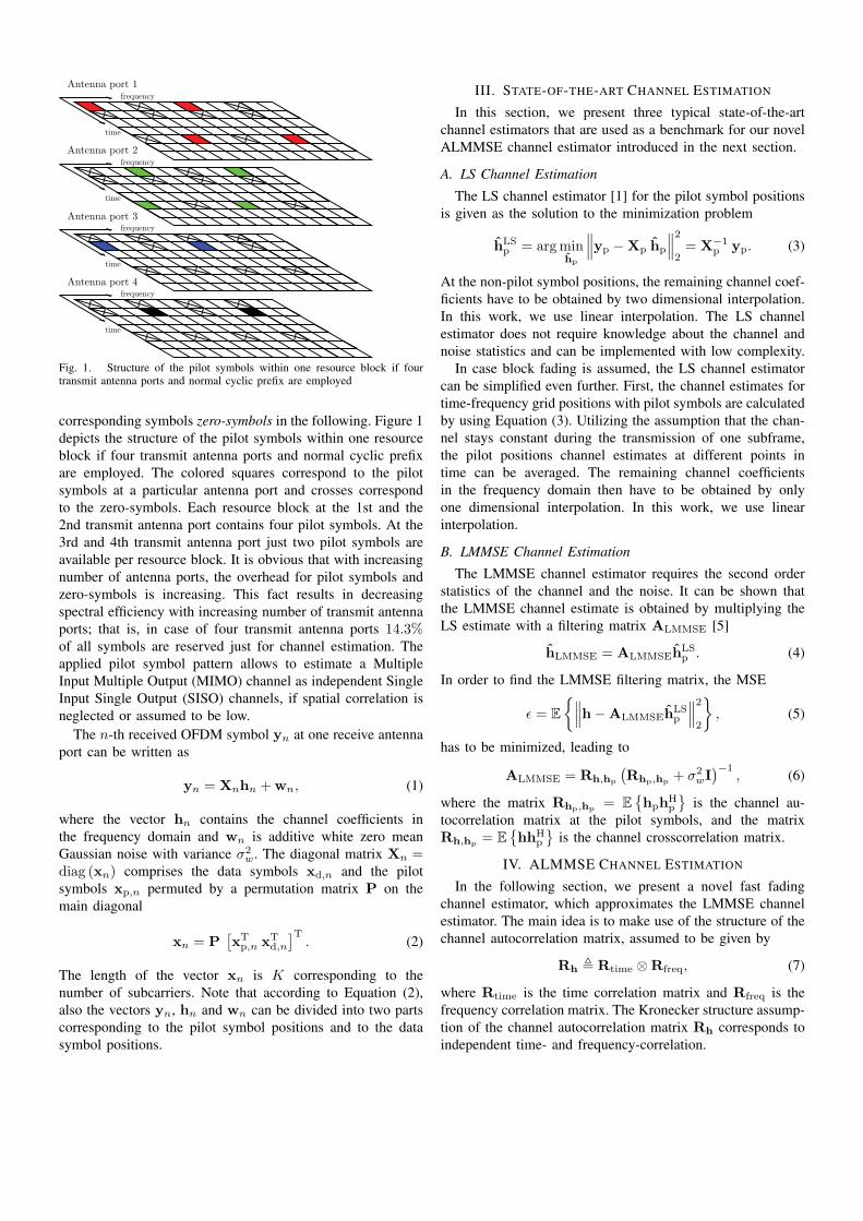
Fig. 1. Structure of the pilot symbols within one resource block if fourtransmit antenna ports and normal cyclic prefix are employed
corresponding symbols zero-symbols in the following. Figure 1depicts the structure of the pilot symbols within one resourceblock if four transmit antenna ports and normal cyclic prefixare employed. The colored squares correspond to the pilotsymbols at a particular antenna port and crosses correspondto the zero-symbols. Each resource block at the 1st and the2nd transmit antenna port contains four pilot symbols. At the3rd and 4th transmit antenna port just two pilot symbols areavailable per resource block. It is obvious that with increasingnumber of antenna ports, the overhead for pilot symbols andzero-symbols is increasing. This fact results in decreasingspectral efficiency with increasing number of transmit antennaports; that is, in case of four transmit antenna ports 14.3%of all symbols are reserved just for channel estimation. Theapplied pilot symbol pattern allows to estimate a MultipleInput Multiple Output (MIMO) channel as independent SingleInput Single Output (SISO) channels, if spatial correlation isneglected or assumed to be low.
The n-th received OFDM symbol yn at one receive antennaport can be written as
yn = Xnhn + wn, (1)
where the vector hn contains the channel coefficients inthe frequency domain and wn is additive white zero meanGaussian noise with variance σ2
w. The diagonal matrix Xn =diag (xn) comprises the data symbols xd,n and the pilotsymbols xp,n permuted by a permutation matrix P on themain diagonal
xn = P[xT
p,n xTd,n
]T. (2)
The length of the vector xn is K corresponding to thenumber of subcarriers. Note that according to Equation (2),also the vectors yn, hn and wn can be divided into two partscorresponding to the pilot symbol positions and to the datasymbol positions.
III. STATE-OF-THE-ART CHANNEL ESTIMATION
In this section, we present three typical state-of-the-artchannel estimators that are used as a benchmark for our novelALMMSE channel estimator introduced in the next section.
A. LS Channel Estimation
The LS channel estimator [1] for the pilot symbol positionsis given as the solution to the minimization problem
hLSp = arg min
hp
∥∥∥yp − Xp hp
∥∥∥2
2= X−1
p yp. (3)
At the non-pilot symbol positions, the remaining channel coef-ficients have to be obtained by two dimensional interpolation.In this work, we use linear interpolation. The LS channelestimator does not require knowledge about the channel andnoise statistics and can be implemented with low complexity.
In case block fading is assumed, the LS channel estimatorcan be simplified even further. First, the channel estimates fortime-frequency grid positions with pilot symbols are calculatedby using Equation (3). Utilizing the assumption that the chan-nel stays constant during the transmission of one subframe,the pilot positions channel estimates at different points intime can be averaged. The remaining channel coefficientsin the frequency domain then have to be obtained by onlyone dimensional interpolation. In this work, we use linearinterpolation.
B. LMMSE Channel Estimation
The LMMSE channel estimator requires the second orderstatistics of the channel and the noise. It can be shown thatthe LMMSE channel estimate is obtained by multiplying theLS estimate with a filtering matrix ALMMSE [5]
hLMMSE = ALMMSEhLSp . (4)
In order to find the LMMSE filtering matrix, the MSE
ε = E
{∥∥∥h − ALMMSEhLSp
∥∥∥2
2
}, (5)
has to be minimized, leading to
ALMMSE = Rh,hp
(Rhp,hp + σ2
wI)−1
, (6)
where the matrix Rhp,hp = E{hphH
p
}is the channel au-
tocorrelation matrix at the pilot symbols, and the matrixRh,hp = E
{hhH
p
}is the channel crosscorrelation matrix.
IV. ALMMSE CHANNEL ESTIMATION
In the following section, we present a novel fast fadingchannel estimator, which approximates the LMMSE channelestimator. The main idea is to make use of the structure of thechannel autocorrelation matrix, assumed to be given by
Rh � Rtime ⊗ Rfreq, (7)
where Rtime is the time correlation matrix and Rfreq is thefrequency correlation matrix. The Kronecker structure assump-tion of the channel autocorrelation matrix Rh corresponds toindependent time- and frequency-correlation.
The standard LMMSE estimate is obtained by minimizingthe error in Equation (5). Let us consider the followingproblem instead
minBfreq,Ctime
E
{‖H − BfreqHLSCT
time‖2F
}, (8)
with the channel H = [h0, · · · ,hNs−1] and the LS channelestimate HLS = [hLS
0 , · · · , hLSNs−1]. Here, Ns denotes the
number of OFDM symbols, Bfreq and Ctime are matrices ofdimension K×K and Ns×Ns, respectively. ‖·‖F refers to theFrobenius norm. The approach in Equation (8) corresponds toa separate filtering of the LS estimate in time and frequency.After applying the vec(·) operator [10] in Equation (8) by
using h = vec (H), hLS = vec(HLS
), and
vec(BfreqHLSCT
time
)= (Ctime ⊗ Bfreq) vec
(HLS
), (9)
we obtain
minBfreq,Ctime
E
{‖h − (Ctime ⊗ Bfreq) hLS‖2
2
}. (10)
The problems formulated in Equation (5) and Equation (10)are equivalent. However, in general ALMMSE cannot alwaysbe decomposed into Ctime ⊗Bfreq. Instead, we are searchingfor the best approximation
ALMMSE ≈ Ctime ⊗ Bfreq. (11)
Due to the pilot symbols pattern utilized in LTE, that isnot equidistant in the time and frequency, the structure fromEquation (7) cannot be exploited in Rhp,hp and Rh,hp .Therefore, we replace the auto- and crosscorrelation matricesin Equation (6) by the channel autocorrelation matrix Rh.Therefore, instead of filtering the LS estimate at the pilotsymbols position, the interpolated LS estimate has to befiltered. The dimension of filtering matrix in Equation (6)is changed from KNs × Np to KNs × KNs, where Np
is the number of the pilot symbols. In the Signal to NoiseRatio (SNR) range of interest, such an estimator performsclose to the true LMMSE channel estimator. For pilot symbolpattern that is equidistant in time frequency, the structure fromEquation (7) can be exploited. Using Equations (6) and (7),the matrix ALMMSE is given by
ALMMSE = Rtime ⊗ Rfreq
(Rtime ⊗ Rfreq + σ2
wI)−1
. (12)
The symmetric matrices Rtime and Rfreq can be rewrittenusing the eigenvalue decomposition as
Rtime = UtimeDtimeUHtime, Rfreq = UfreqDfreqUH
freq,
where Dtime and Dfreq are diagonal matrices, with theircorresponding eigenvalues ordered from largest to smallest onthe main diagonal. Utime and Ufreq are unitary matrices com-prising the eigenvectors of the given matrices. Furthermore,due to the Kronecker product properties, one can write
Rtime ⊗ Rfreq = (Utime ⊗ Ufreq)Dh (Utime ⊗ Ufreq)H
,
where Dh is a diagonal matrix with eigenvalues of the matrixRtime⊗Rfreq, being equal to Dtime⊗Dfreq. Inserting the last
equation into Equation (12) and after some linear algebra, thefiltering matrix becomes
ALMMSE =
(Utime ⊗ Ufreq)Dh
(Dh + σ2
wI)−1
(Utime ⊗ Ufreq)H
.
A. Rank-One Approximation
Let us assume that Bfreq and Ctime have the same eigen-vectors as Rfreq and Rtime. Then Equation (11) can beapproximated by
ALMMSE =
UhDh
(Dh + σ2
wI)−1
UHh ≈ UhDCtime⊗BfreqU
Hh , (13)
with Uh = Utime ⊗ Ufreq. The matrix DCtime⊗Bfreq isa diagonal matrix comprising the eigenvalues of the matrixCtime ⊗ Bfreq.
Moreover, let λtime, λfreq, λCtimeand λBfreq
denote thevectors of the eigenvalues of Rtime, Rfreq, Ctime and Bfreq,respectively. By multiplying λtime with λT
freq, a matrix isobtained that comprises all possible multiplications of theelements of the vectors, and thus the eigenvalues of thematrix Rtime ⊗ Rfreq. To solve the approximation problemDCtime⊗Bfreq ≈ Dh
(Dh + σ2
wI)−1
, the eigenvalues of thematrix Ctime ⊗ Bfreq have to be found. Those represent allpossible multiplications of the eigenvalues of the matricesCtime and Bfreq, given by λCtime
λTBfreq
. Using the matricesλtimeλ
Tfreq and λCtime
λTBfreq
, the problem can be reformulatedas
λtimeλTfreq./
(λtimeλ
Tfreq + σ2
w11T)≈ λCtime
λTBfreq
, (14)
where 1 is the all ones vector and ./ denotes element-wisedivision. This is a so-called rank-one approximation, wherethe best approximation is achieved when taking the left andright eigenvectors corresponding to the largest singular value,and having one of them scaled by it
λCtime= σmaxumax, (15)
λBfreq= vmax. (16)
Accordingly, the ALMMSE channel estimate utilizing therank-one approximation of Equation (14) is given by
HALMMSE = BfreqHLSCTtime, (17)
where the matrices Bfreq and Ctime are given by
Bfreq = Ufreqdiag(λBfreq
)UH
freq, (18)
Ctime = Utimediag(λCtime
)UH
time. (19)
B. Complexity Scaling
By utilizing the truncated Singular Value Decomposition(SVD) [11] on Rtime and Rfreq, Ntime and Nfreq largesteigenvalues can be obtained, respectively. By using Equa-tion (14), the vectors λCtime
and λBfreqof length Ntime and
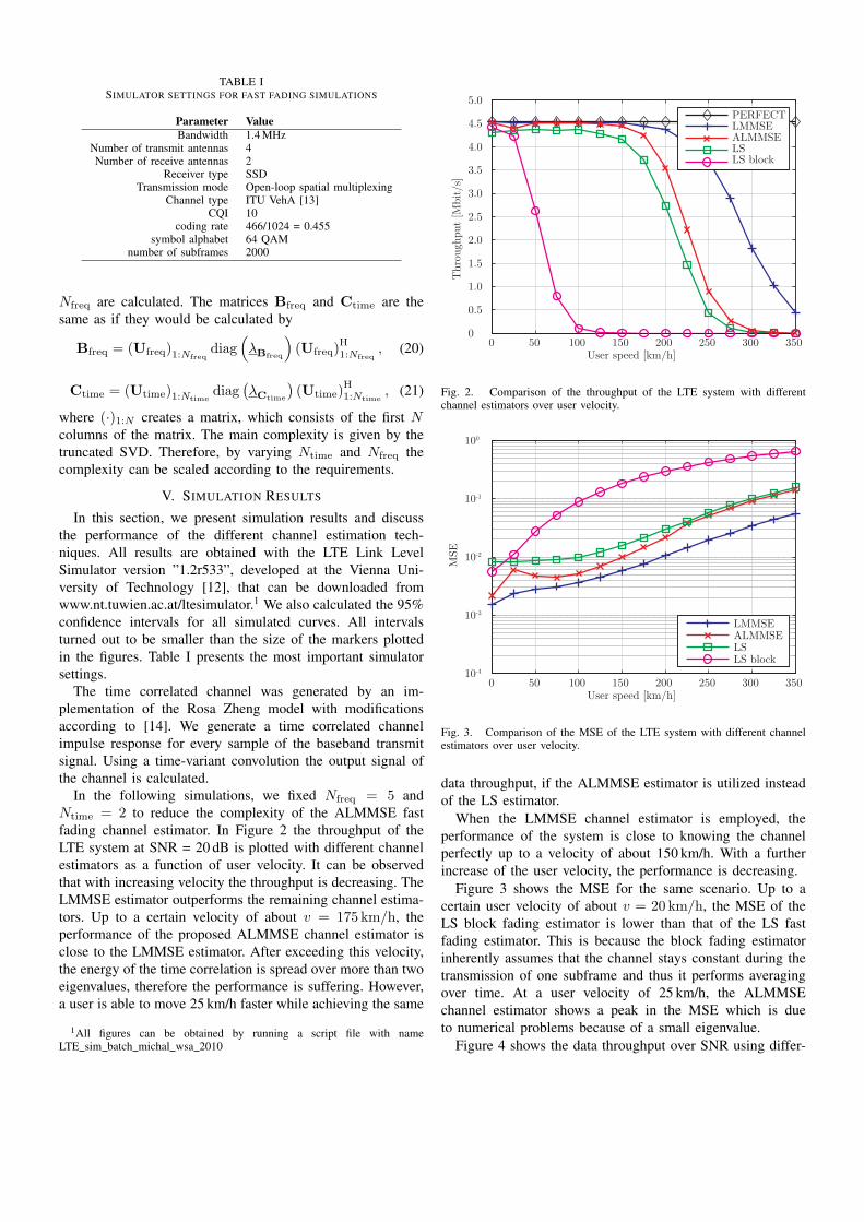
TABLE ISIMULATOR SETTINGS FOR FAST FADING SIMULATIONS
Parameter ValueBandwidth 1.4 MHz
Number of transmit antennas 4Number of receive antennas 2
Receiver type SSDTransmission mode Open-loop spatial multiplexing
Channel type ITU VehA [13]CQI 10
coding rate 466/1024 = 0.455symbol alphabet 64 QAM
number of subframes 2000
Nfreq are calculated. The matrices Bfreq and Ctime are thesame as if they would be calculated by
Bfreq = (Ufreq)1:Nfreqdiag
(λBfreq
)(Ufreq)
H1:Nfreq
, (20)
Ctime = (Utime)1:Ntimediag
(λCtime
)(Utime)
H1:Ntime
, (21)
where (·)1:N creates a matrix, which consists of the first Ncolumns of the matrix. The main complexity is given by thetruncated SVD. Therefore, by varying Ntime and Nfreq thecomplexity can be scaled according to the requirements.
V. SIMULATION RESULTS
In this section, we present simulation results and discussthe performance of the different channel estimation tech-niques. All results are obtained with the LTE Link LevelSimulator version ”1.2r533”, developed at the Vienna Uni-versity of Technology [12], that can be downloaded fromwww.nt.tuwien.ac.at/ltesimulator.1 We also calculated the 95%confidence intervals for all simulated curves. All intervalsturned out to be smaller than the size of the markers plottedin the figures. Table I presents the most important simulatorsettings.
The time correlated channel was generated by an im-plementation of the Rosa Zheng model with modificationsaccording to [14]. We generate a time correlated channelimpulse response for every sample of the baseband transmitsignal. Using a time-variant convolution the output signal ofthe channel is calculated.
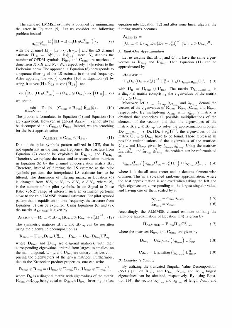
In the following simulations, we fixed Nfreq = 5 andNtime = 2 to reduce the complexity of the ALMMSE fastfading channel estimator. In Figure 2 the throughput of theLTE system at SNR = 20 dB is plotted with different channelestimators as a function of user velocity. It can be observedthat with increasing velocity the throughput is decreasing. TheLMMSE estimator outperforms the remaining channel estima-tors. Up to a certain velocity of about v = 175 km/h, theperformance of the proposed ALMMSE channel estimator isclose to the LMMSE estimator. After exceeding this velocity,the energy of the time correlation is spread over more than twoeigenvalues, therefore the performance is suffering. However,a user is able to move 25 km/h faster while achieving the same
1All figures can be obtained by running a script file with nameLTE sim batch michal wsa 2010
0 50 100 150 200 250 300 3500
0.5
1.0
1.5
2.0
2.5
3.0
3.5
4.0
4.5
5.0
User speed [km/h]
Thr
ough
put
[Mbi
t/s]
PERFECTLMMSEALMMSELSLS block
Fig. 2. Comparison of the throughput of the LTE system with differentchannel estimators over user velocity.
0 50 100 150 200 250 300 35010-4
10-3
10-2
10-1
100
User speed [km/h]
MSE
LMMSEALMMSELSLS block
Fig. 3. Comparison of the MSE of the LTE system with different channelestimators over user velocity.
data throughput, if the ALMMSE estimator is utilized insteadof the LS estimator.
When the LMMSE channel estimator is employed, theperformance of the system is close to knowing the channelperfectly up to a velocity of about 150 km/h. With a furtherincrease of the user velocity, the performance is decreasing.
Figure 3 shows the MSE for the same scenario. Up to acertain user velocity of about v = 20 km/h, the MSE of theLS block fading estimator is lower than that of the LS fastfading estimator. This is because the block fading estimatorinherently assumes that the channel stays constant during thetransmission of one subframe and thus it performs averagingover time. At a user velocity of 25 km/h, the ALMMSEchannel estimator shows a peak in the MSE which is dueto numerical problems because of a small eigenvalue.
Figure 4 shows the data throughput over SNR using differ-
0 5 10 15 20 25 300
0.5
1.0
1.5
2.0
2.5
3.0
3.5
4.0
4.5
5.0
SNR [dB]
Thr
ough
put
[Mbi
t/s]
PERFECTLMMSEALMMSELSLS block
Fig. 4. Throughput of the LTE system using different channel estimators atuser speed of 60 km/h.
0 5 10 15 20 25 3010-4
10-3
10-2
10-1
100
SNR [dB]
MSE
LMMSEALMMSELSLS block
Fig. 5. Mean square error of the different channel estimators at user speedof 60 km/h
ent channel estimators. At 90% of the maximum throughput,the performance loss of the ALMMSE estimator with respectto the LMMSE estimator is approximately 0.1 dB. We measurethe the performance loss at 90% of the maximum throughput,because it is operating point, where the mobile operator wouldlike to operate their systems. In the low SNR region, theLS block fading estimator slightly outperforms the LS fastfading estimator due its averaging over time, which effectivelysuppresses noise.
Correspondingly, Figure 5 depicts the MSE of the pre-sented channel estimators for a user velocity of 60 km/h.With increasing SNR, the difference in MSE between theALMMSE estimator and the LMMSE estimator, is decreasing.Furthermore, it can be observed that the MSE of the LSblock fading estimator saturates. The MSE of all other channelestimators is decreasing with increasing SNR.
0 50 100 150 2000
0.5
1.0
1.5
2.0
2.5
3.0
3.5
4.0
4.5
5.0
User speed [km/h]
Thr
ough
put
[Mbi
t/s]
LS
LMMSE
Ntime=2 Nfreq=5Ntime=2 Nfreq=4Ntime=2 Nfreq=3Ntime=1 Nfreq=1
Fig. 6. Throughput of the LTE system using ALMMSE channel estimatorwith different number of eigenvalues over user speed
In Figure 6 the throughput as a function user velocityat SNR = 20 dB is depicted for the ALMMSE channelestimator using different Nfreq and Ntime. By varying thenumber of considered eigenvalues, the complexity of theALMMSE channel estimator can be adjusted; however, alsothe achievable performance is affected. For the case Nfreq = 1and Ntime = 1, the performance is limited that much thatno throughput is achieved. This is caused by ignoring largeeigenvalues.
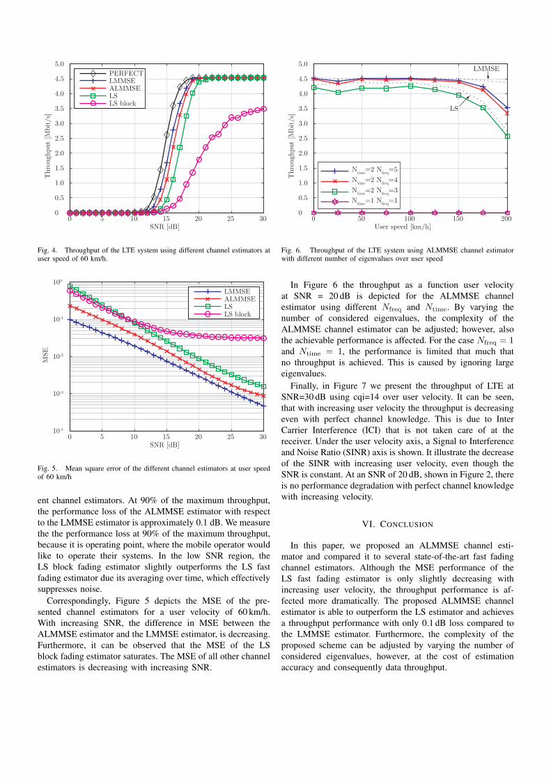
Finally, in Figure 7 we present the throughput of LTE atSNR=30 dB using cqi=14 over user velocity. It can be seen,that with increasing user velocity the throughput is decreasingeven with perfect channel knowledge. This is due to InterCarrier Interference (ICI) that is not taken care of at thereceiver. Under the user velocity axis, a Signal to Interferenceand Noise Ratio (SINR) axis is shown. It illustrate the decreaseof the SINR with increasing user velocity, even though theSNR is constant. At an SNR of 20 dB, shown in Figure 2, thereis no performance degradation with perfect channel knowledgewith increasing velocity.
VI. CONCLUSION
In this paper, we proposed an ALMMSE channel esti-mator and compared it to several state-of-the-art fast fadingchannel estimators. Although the MSE performance of theLS fast fading estimator is only slightly decreasing withincreasing user velocity, the throughput performance is af-fected more dramatically. The proposed ALMMSE channelestimator is able to outperform the LS estimator and achievesa throughput performance with only 0.1 dB loss compared tothe LMMSE estimator. Furthermore, the complexity of theproposed scheme can be adjusted by varying the number ofconsidered eigenvalues, however, at the cost of estimationaccuracy and consequently data throughput.
0 50 100 150 200 250 300 3500
1
2
3
4
5
6
7
8
9
User speed [km/h]
Thr
ough
put
[Mbi
t/s]
PERFECTLMMSEALMMSELSLS block
30 29.7 29.0 28.0 26.8 25.7 24.7 23.7SINR [dB]
Fig. 7. Throughput of the LTE system with cqi=14 using different channelestimators over user speed at SNR=30 dB
ACKNOWLEDGMENT
This work has been funded by the Christian Doppler Labo-ratory for Wireless Technologies for Sustainable Mobility, theInstitute of Communications and Radio-Frequency Engineer-ing, KATHREIN-Werke KG, and mobilkom austria AG.
REFERENCES
[1] J. J. van de Beek, O. Edfors, M. Sandell, S. K. Wilson, and P. O.Borjesson, “On channel estimation in OFDM systems,” in Proc.IEEE 45th Vehicular Technology Conference (VTC 1995), 1995,vol. 2, pp. 815–819.
[2] S. Coleri, M. Ergen, A. Puri, and A. Bahai, “Channel estimationtechniques based on pilot arrangement in ofdm systems,” IEEETransactions on Broadcasting, vol. 48, no. 3, pp. 223–229, Sep2002.
[3] Ye Li, “Pilot-symbol-aided channel estimation for OFDM inwireless systems,” in 1999 IEEE 49th Vehicular TechnologyConference, Jul 1999, vol. 2, pp. 1131–1135 vol.2.
[4] Christian Mehlfuhrer, Sebastian Caban, and Markus Rupp,“An accurate and low complex channel estimator for OFDMWiMAX,” in Proc. Third International Symposium on Com-munications, Control, and Signal Processing (ISCCSP 2008),St. Julians, Malta, Mar. 2008, pp. 922–926.
[5] S. Omar, A. Ancora, and D.T.M. Slock, “Performance analysisof general pilot-aided linear channel estimation in LTE OFDMAsystems with application to simplified MMSE schemes,” in2008. PIMRC 2008. IEEE 19th International Symposium onPersonal, Indoor and Mobile Radio Communications, Sept.2008, pp. 1–6.
[6] Peter Hoeher, Stefan Kaiser, and Patrick Robertson, “Pilot-symbol-aided channel estimation in time and frequency,” in InProc. IEEE Global Telecommunications Conference (GLOBE-COM 97), Communication Theory Mini-Conference, 1997, pp.90–96.
[7] P. Fertl and G. Matz, “Efficient OFDM channel estimation inmobile environments based on irregular sampling,” in Proc of.Fortieth Annual Asilomar Conference on Signals, Systems, andComputers, Pacific Grove, CA, USA, October 2006.
[8] Won-Gyu Song and Jong-Tae Lim, “Pilot-symbol aided channelestimation for ofdm with fast fading channels,” IEEE Transac-tions on Broadcasting, vol. 49, no. 4, pp. 398–402, Dec. 2003.
[9] 3GPP, “Evolved Universal Terrestrial Radio Access (E-UTRA);Physical channels and modulation,” TS 36.211, 3rd GenerationPartnership Project (3GPP), Sept. 2008.
[10] T. K. Moon and W. C. Stirling, Mathematical Methods andAlgorithms for Signal Processing, Prentice Hall, Upper SaddleRiver, NJ, 2000.
[11] Moody T. Chu, Robert E. Funderlic, and Robert J. Plemmons,“Structured low rank approximation,” Linear Algebra and itsApplications, vol. 366, pp. 157–172, 2003.
[12] Christian Mehlfuhrer, Martin Wrulich, Josep Colom Ikuno,Dagmar Bosanska, and Markus Rupp, “Simulating the long termevolution physical layer,” in Proc. of the 17th European SignalProcessing Conference (EUSIPCO 2009), Glasgow, Scotland,Aug. 2009.
[13] ITU, “Recommendation ITU-R M.1225: Guidelines for evalua-tion of radio transmission technologies for IMT- 2000 systems,”Recommendation ITU-R M.1225, International Telecommuni-cation Union, 1998.
[14] T. Zemen and C.F. Mecklenbrauker, “Time-variant channelestimation using discrete prolate spheroidal sequences,” IEEETransactions on Signal Processing, vol. 53, no. 9, pp. 3597–3607, Sept. 2005.