Embed Size (px)
Citation preview
4.01
mab
ey h
ire s
erv
ices lim
ited
|
01924 4
60 6
01 |
ww
w.m
ab
eyhireserv
ices.c
om
gro
und
work
s t
echnic
al re
fere
nce |
section 4
: d
oub
le a
cting
hyd
raulic b
races
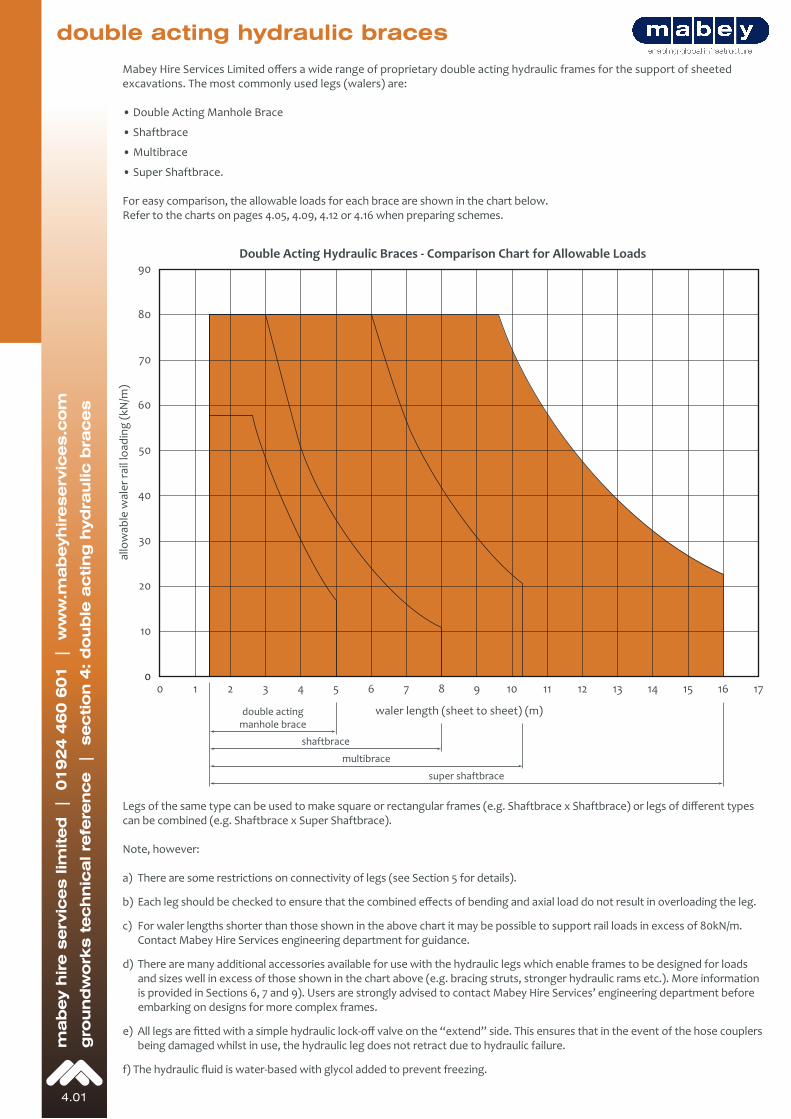
double acting hydraulic braces
allo
wab
le w
aler
rail
load
ing
(kN
/m)
waler length (sheet to sheet) (m)
0 1 2 3 4 5 6 7 8 9 10 11 12 13 14 15 16 17
90
80
70
60
50
40
30
20
10
0
double actingmanhole brace
shaftbrace
multibrace
super shaftbrace
excavations. The most commonly used legs (walers) are:
• Double Acting Manhole Brace
• Shaftbrace
• Multibrace
• Super Shaftbrace.
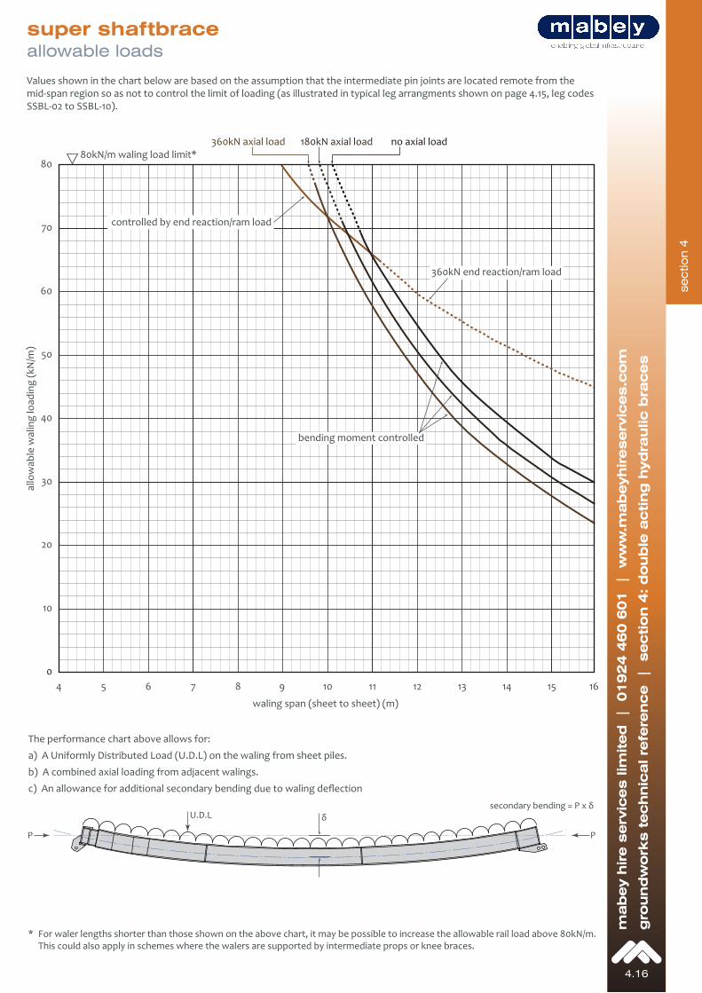
For easy comparison, the allowable loads for each brace are shown in the chart below.Refer to the charts on pages 4.05, 4.09, 4.12 or 4.16 when preparing schemes.
can be combined (e.g. Shaftbrace x Super Shaftbrace).
Note, however:
a) There are some restrictions on connectivity of legs (see Section 5 for details).
b)
c) For waler lengths shorter than those shown in the above chart it may be possible to support rail loads in excess of 80kN/m. Contact Mabey Hire Services engineering department for guidance.
d) There are many additional accessories available for use with the hydraulic legs which enable frames to be designed for loads and sizes well in excess of those shown in the chart above (e.g. bracing struts, stronger hydraulic rams etc.). More information is provided in Sections 6, 7 and 9). Users are strongly advised to contact Mabey Hire Services’ engineering department before embarking on designs for more complex frames.
e) being damaged whilst in use, the hydraulic leg does not retract due to hydraulic failure.
f)
Double Acting Hydraulic Braces - Comparison Chart for Allowable Loads
4.13
mab
ey h
ire s
erv
ices lim
ited
|
01924 4
60 6
01 |
ww
w.m
ab
eyhireserv
ices.c
om
gro
und
work
s t
echnic
al re
fere
nce |
section 4
: d
oub
le a
cting
hyd
raulic b
races
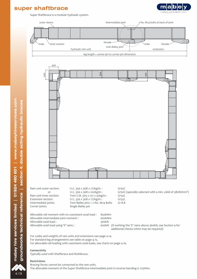
super shaftbrace
hydraulic ram unit
leg length = corner pin to corner pin dimension
extensiontwin Bailey pins
2 No. M24 bolts at back of jointintermediate joint
inner section
outer sleeve
male femalefemale
male
440
440
370
510
Ram unit outer section: U.C. 356 x 368 x 177kg/m : Gr55C or U.C. 356 x 368 x 202kg/m : Gr50C (specially selected with a min. yield of 380N/mm2)Ram unit inner section: Twin U.B. 305 x 127 x 42kg/m : Gr55CExtension section: U.C. 356 x 368 x 177kg/m : Gr55CIntermediate joints: Twin Bailey pins + 2 No. M24 Bolts Gr 8.8Corner joints: Single Bailey pin
Allowable rail moment with no coexistent axial load : 850kNmAllowable intermediate joint moment : 600kNmAllowable axial load : 360kNAllowable axial load using ‘E’ rams : 600kN (if working the ‘E’ rams above 360kN, see Section 9 for additional checks which may be required)
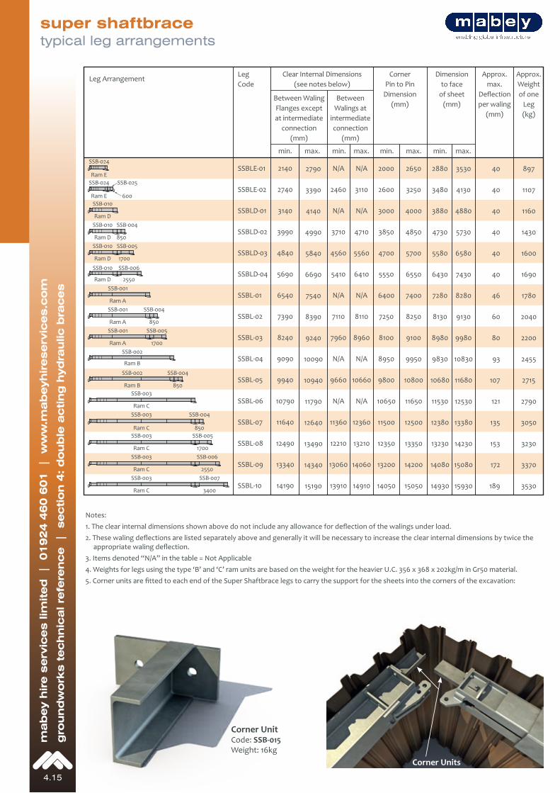
For codes and weights of ram units and extensions see page 4.14.For standard leg arrangements see table on page 4.15.For allowable rail loading with coexistent axial loads, see charts on page 4.16.
ConnectivityTypically used with Shaftbrace and Multibrace.
RestrictionsBracing Struts cannot be connected to the ram units.The allowable moment of the Super Shaftbrace intermediate joint in reverse bending is 125kNm.
Super Shaftbrace is a modular hydraulic system.
sectio
n 4
4.14
mab
ey h
ire s
erv
ices lim
ited
|
01924 4
60 6
01 |
ww
w.m
ab
eyhireserv
ices.c
om
gro
und
work
s t
echnic
al re
fere
nce |
section 4
: d
oub
le a
cting
hyd
raulic b
races
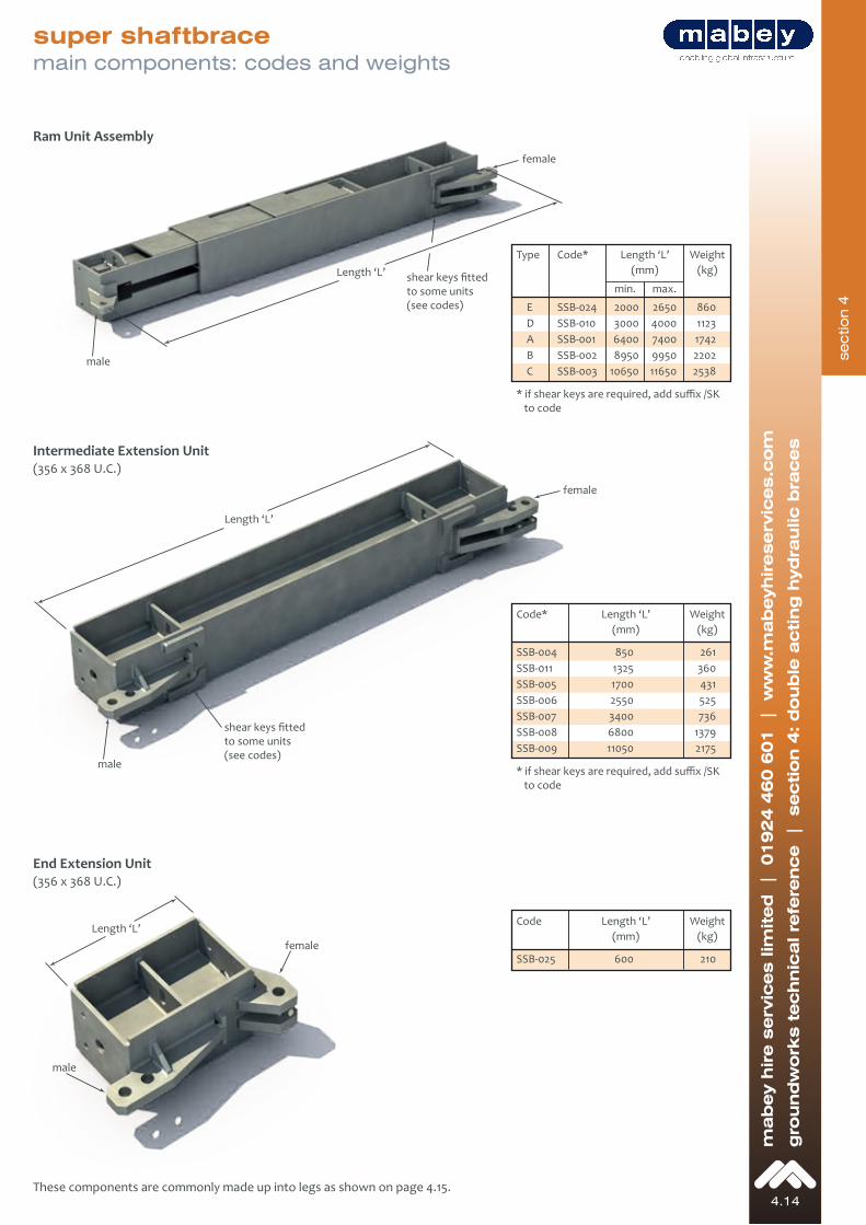
super shaftbracemain components: codes and weights
Ram Unit Assembly
Intermediate Extension Unit
End Extension Unit
to code
to code
shear keys fitted
(see codes)
shear keys fitted
(see codes)
4.15
mab
ey h
ire s
erv
ices lim
ited
|
01924 4
60 6
01 |
ww
w.m
ab
eyhireserv
ices.c
om
gro
und
work
s t
echnic
al re
fere
nce |
section 4
: d
oub
le a
cting
hyd
raulic b
races
super shaftbracetypical leg arrangements
Corner UnitSSB-015
connection connection
Deflection
Corner Units
sectio
n 4
4.16
mab
ey h
ire s
erv
ices lim
ited
|
01924 4
60 6
01 |
ww
w.m
ab
eyhireserv
ices.c
om
gro
und
work
s t
echnic
al re
fere
nce |
section 4
: d
oub
le a
cting
hyd
raulic b
races
super shaftbraceallowable loads
P P
δsecondary bending = P x δ