Embed Size (px)
Citation preview
DOT/FAA/TC-13/25, P1 Federal Aviation Administration William J. Hughes Technical Center Aviation Research Division Atlantic City International Airport New Jersey 08405
Development of a New Metal Material Model in LS-DYNA®
Part 1: FAA, NASA, and Industry Collaboration Background April 2014 Final Report This document is available to the U.S. public through the National Technical Information Services (NTIS), Springfield, Virginia 22161. This document is also available from the Federal Aviation Administration William J. Hughes Technical Center at actlibrary.tc.faa.gov.
U.S. Department of Transportation Federal Aviation Administration

NOTICE
This document is disseminated under the sponsorship of the U.S. Department of Transportation in the interest of information exchange. The U.S. Government assumes no liability for the contents or use thereof. The U.S. Government does not endorse products or manufacturers. Trade or manufacturers’ names appear herein solely because they are considered essential to the objective of this report. The findings and conclusions in this report are those of the author(s) and do not necessarily represent the views of the funding agency. This document does not constitute FAA policy. Consult the local FAA sponsoring organization listed on the Technical Documentation page as to its use. This report is available at the Federal Aviation Administration William J. Hughes Technical Center’s Full-Text Technical Reports page: actlibrary.tc.faa.gov in Adobe Acrobat portable document format (PDF).
Technical Report Documentation Page
1. Report No.
DOT/FAA/TC-13/25, P1
2. Gov ernment Accession No. 3. Recipient's Catalog No.
4. Title and Subtitle
DEVELOPMENT OF A NEW METAL MATERIAL MODEL IN LS-DYNA® PART 1: FAA, NASA, AND INDUSTRY COLLABORATION BACKGROUND
5. Report Date
April 2014 7. Author(s)
William Emmerling1, Donald Altobelli1, Kelly Carney2, and Mike Pereira2
8. Perf orming Organization Report No.
9. Perf orming Organization Name and Address 1Federal Aviation Administration William J. Hughes Technical Center Atlantic City International Airport, NJ 08405
10. Work Unit No. (TRAIS)
2NASA Glenn Research Center 21000 Brookpark Road Cleveland, OH 44135
11. Contract or Grant No.
12. Sponsoring Agency Name and Address
U.S. Department of Transportation Federal Aviation Administration
13. Ty pe of Report and Period Cov ered
Office of Aviation Research and Development Washington, D.C. 20591
14. Sponsoring Agency Code
ANE-110 15. Supplementary Notes
The Federal Aviation Administration William J. Hughes Technical Center Aviation Research Division CORs were William Emmerling and Donald Altobelli. This work was performed under the FAA Aircraft Catastrophic Failure Prevention Program. 16. Abstract
The Federal Aviation Administration and National Aeronautics and Space Administration have been working together with academia and industry since 1997 on research to mitigate the effects of uncontained engine failures. Significant work has been performed over the last several years, capitalizing on advancement in computing technology and testing technology. This multipart report presents development in each of these areas, including a new material model in the Livermore Software Explicit Finite Element Code (LS-DYNA®) explicit modeling code for 2024 T3/T351 aluminum. Academic contributors to this report are from The George Washington University and The Ohio State University. This report is separated into three parts that focus on both the modeling and testing aspects of this work from inception to validation. This first part of the report details the background from early workshops, challenges encountered and reported in previous work, and the current physics-based tabulated approach that has made significant strides to solve a problem identified in modeling for many years—that, although models could be tuned to match testing and a type of failure, a single material model would not accurately predict the crossover in failure modes. The MAT Tabulated Johnson Cook (LS-DYNA MAT 224) is the new constitutive material model developed under this joint effort; it has provided the means for predicting multiple modes of failure and, along with other quality control and guidance materials developed by the group, significantly advances the overall process toward the goal of certification by analysis. Future work will concentrate on additional metals because these metals will require material-specific input parameters, and may require adjustments to the constitutive model, to be able to characterize the unique properties of those metals. 17. Key Words
Uncontained, LS-DYNA, Engine, Impact, Material model, Failure, Stress, Strain, Plasticity
18. Distribution Statement
This document is available to the U.S. public through the National Technical Information Service (NTIS), Springfield, Virginia 22161. This document is also available from the Federal Aviation Administration William J. Hughes Technical Center at actlibrary.tc.faa.gov.
19. Security Classif . (of this report) Unclassified
20. Security Classif . (of this page) Unclassified
21. No. of Pages 26
22. Price
Form DOT F 1700.7 (8-72) Reproduction of completed page authorized

ACKNOWLEDGEMENT The Federal Aviation Administration (FAA), National Aeronautics and Space Administration (NASA), and industry team wish to thank Livermore Software Technology Corporation for their support of the Aerospace Working Group’s efforts to improve the aerospace industry’s ability to use explicit finite element analysis for impact problems related to turbine engine fragment impact experienced during turbine engine fan blade-out events and rotorburst events. The authors would also like to thank FAA Chief Scientists for Engine Dynamics Chester Lewis (retired) and Gilbert (Chip) Queitzsch for providing valuable support and guidance to the program.
iii/iv

TABLE OF CONTENTS
Page
EXECUTIVE SUMMARY viii 1. INTRODUCTION 1
1.1 Purpose 1 1.2 Background 1 1.3 Related Activities and Documents 3
2. DISCUSSION 3
2.1 The LS-DYNA AWG 6
2.1.1 Background 6 2.1.2 Planned Deliverables of the LS-DYNA AWG 7
2.2 Development of the MAT 224 8
2.2.1 Metal Failure Analysis 8 2.2.2 2024 T3/T351 Aluminum Input Parameters for MAT 224 10
2.3 Testing of 2024 T3/T351 Aluminum 11
2.3.1 Material Selection 11 2.3.2 Material Characterization Testing 12 2.3.3 Impact Testing 14
3. SUMMARY 16 4. REFERENCES 17
v

LIST OF FIGURES Figure Page 1 Typical Stress Strain Curve for Aluminum 4 2 Failure Mode Transition With Thickness and Projectile Energy 5 3 The J-C MAT 15 Compared to Test Data for 2024 Aluminum Target 5 4 Displacement Results From Multiple Computing Platforms, Showing Consistency 7 5 Ballistic Test vs. MAT 15 Predictions 9 6 Triaxiality vs. Failure Plastic Strain Comparison of MAT 224 and J-C Models 10 7 The MAT 224 Failure Surface for 2024 T3/T351 Aluminum 11 8 Test Specimen Machining 12 9 Tensile Test Force Displacement Curve 13 10 The DIC Image Just Prior to Failure for Tension Specimens With Different Size Notches 14 11 Large NASA Gas Gun With Vacuum Chamber 15 12 Ballistic Test Results Using Cylindrical Projectiles on AL2024 Panels With
Thicknesses of 0.125 inch, 0.25 inch, and 0.5 inch 16
vi

LIST OF ACRONYMS AND ABBREVIATIONS 3D Three-dimensional ACFPP Aircraft Catastrophic Failure Prevention Program AWG Aerospace Working Group CFR Code of Federal Regulations DC-10 McDonnell Douglas DC-10 DIC Digital image correlation FAA Federal Aviation Administration GWU The George Washington University J-C Johnson-Cook LLNL Lawrence Livermore National Laboratory LS-DYNA Livermore Software Explicit Finite Element Code LSTC Livermore Software Technology Corporation MAT LS-DYNA keyword for material model MAT 224 MAT Tabulated Johnson Cook NASA National Aeronautics and Space Administration NASA-GRC National Aeronautics and Space Administration-Glenn Research Center OSU The Ohio State University QA Quality assurance UCB University of California at Berkeley
vii
EXECUTIVE SUMMARY
A team consisting of members from The Ohio State University (OSU), The George Washington University (GWU), the National Aeronautics and Space Administration Glenn Research Center (NASA–GRC), and the Federal Aviation Administration (FAA) Aircraft Catastrophic Failure Prevention Program (ACFPP) collaborated to develop a new material model in Livermore Software Explicit Finite Element Code (LS-DYNA®) for 2024 T3/T351 aluminum. The definition of the material behavior in the model uses tabulated data based on comprehensive material testing performed by OSU. This research was conducted under an FAA Grant and was sponsored by the ACFPP. The research was directed toward improving the numerical modeling of turbine engine blade-out containment tests required for certification of aircraft engines.
This is part 1 of a three-part report, organized as follows: • Part 1—FAA, NASA, and Industry Collaboration Background
• Part 2—Development of MAT 224 Material Model and the Specific Input Parameters for
2024 T3/T351 Aluminum
• Part 3—Plastic Deformation and Ductile Fracture of 2024 Aluminum Under Various Loading Conditions
There are two FAA reports (DOT/FAA/TC-12/58 and DOT/FAA/TC-12/16) that complement this research on the same 2024 aluminum material that were published separately by NASA–GRC and The University of California at Berkeley and document impact testing conducted for the purpose of validating the new material model. This first part of the report details the background from the early workshops, challenges encountered and reported in previous work, and the current physics-based tabulated approach. This approach has made significant progress toward solving a problem that has had limited certification by analysis efforts for many years. That is, existing models could be tuned to match testing and a particular type of failure, but a single material model would not accurately predict the crossover from one type of failure to another, with changing impact conditions (e.g., petaling to plugging failures). The new constitutive material model developed under this joint effort, Mat Tabulated Johnson-Cook (MAT 224), is the first major step in providing the needed accuracy for predicting material failure under the impact conditions of concern. This improved predictive capability, along with other quality control and guidance materials developed by the group, significantly advances the acceptability of the overall analytical process toward the goal of certification by analysis.
viii

1. INTRODUCTION.
1.1 PURPOSE. Since the mid-1990s, the Federal Aviation Administration (FAA) Aircraft Catastrophic Failure Prevention Program (ACFPP) has sponsored research addressing the design issues encountered during the certification process with the goal of minimizing the hazard to the aircraft from uncontained engine debris, as defined in Title 14 of the Code of Federal Regulations (CFR) 25.903. The impact analysis problem encountered is very similar to the analysis for certification of engine fan blade-out containment Title 14 CFR 33.94. Each of these areas required extensive analysis that was beyond the capabilities of the technology at the time. The FAA ACFPP and National Aeronautics and Space Administration–Glenn Research Center’s (NASA–GRC) Impact Dynamics Group have a long history of collaboration on impact testing and analysis for aircraft safety. The team has worked together on parallel safety efforts, coordinating to develop test data and analysis capabilities that have advanced the state of the art used in modeling metals, composites, and impact-resistant fabrics for aerospace vehicle safety. The development of improved materials data and analytical capability is the centerpiece of the collaboration. Through the years, the team’s goal has been a physics-based analysis that can accurately predict the mode of failure and the extent of damage during turbine engine fragment impact with either engine or aircraft structure. Recently, advances in analytical capabilities have resulted in new modeling techniques that can be used in the design process to improve safety and streamline the certification process. This report documents work on the development of a new constitutive material model for metals that can be used in such an analysis and its usage for modeling 2024 T3/T351 aluminum. The approach used for modeling this alloy is currently being extended to other metallic and composite materials. 1.2 BACKGROUND. On July 19, 1989, a McDonnell Douglas DC-10 (DC-10) experienced an uncontained engine failure while in cruise flight that disabled the triple redundant flight control systems to the extent that stick and rudder pilot inputs were useless. The flight crew was able to use differential engine power to crudely control the plane to a crash landing at Sioux City International Airport, South Dakota. Of the 296 passengers and crew onboard, there were 111 fatalities. Congress established the FAA ACFPP in 1990 (Public Law 101-508) with the purpose of improving aircraft system safety. The program has focused on uncontained engine failure modeling and mitigation as a primary area of research since its inception. From 1994 to 2002, five workshops were held with government, industry, and academia in support of the Aviation Rulemaking Advisory Committee and the Powerplant Installation Harmonization Working Group. During the early workshops, the state of the art in modeling and analysis was discussed, along with research goals and objectives that would improve the design tool box and, ultimately, aircraft safety. The industry representative asked the FAA to help them improve the analytical modeling capability for the code they had chosen for impact analysis, DYNA3D. During the early research work, DYNA3D became a commercial product and today is known as Livermore Software Explicit Finite Element Code (LS-DYNA®). This finite element analysis code is used
1

for the analysis of impact, crash, ballistics, and explosions. Aerospace engine manufacturers use it for fan blade containment analysis. Initially, the FAA research program had three major efforts: aircraft vulnerability analysis of the rotorburst event, modeling of fragment impacts with existing aircraft structure, and developing lightweight protection systems that could be used as shielding. Naval Air Warfare Center China Lake, Lawrence Livermore National Laboratory (LLNL), and SRI International led each effort, respectively. FAA research has included extensive impact testing of simulated engine fragments on aircraft fuselage and engine casing targets. Several metals, fabrics, and composites have been tested as impact shielding. This testing has concentrated on providing a baseline, which has been used to improve impact material models. The resulting improved models enable reliable analytical methods to be developed in support of certification by analysis of derivative engine containment and increased safety and reduced costs. FAA research has also included the development of an aircraft vulnerability model called the Uncontained Engine Debris Damage Assessment Model, which can assess aircraft vulnerability to engine fragments from uncontained engine failures. In 2002, the FAA established an Airworthiness Assurance Center of Excellence, and funds were available for that Center contingent on an industry cost match. The FAA ACFPP funded two programs: a team from LLNL, the University of California at Berkeley (UCB), and The Boeing Company would research the impact problem on metallic fuselages; this also included work on further developing fabric fuselage shielding with SRI International. A second team from Arizona State University, NASA–GRC, SRI International, and Honeywell Engines would conduct research on improving engine fabric containment modeling. In the end, the analytical tools developed, if perfected, should work for both aircraft fuselage shielding and engine containment shielding problems. Two important issues became obstacles in the implementation of material models developed in these programs: 1. When running the same LS-DYNA simulation on multiple computers, the results varied
from one computer to another. Because of this finding, the LS-DYNA Aerospace Working Group (AWG), with Livermore Software Technology Corporation (LSTC) was established, in which aerospace-related problems were developed and incorporated into the LS-DYNA model quality control system at LSTC. This users group has also been instrumental in establishing modeling guidelines for LS-DYNA that benefits government and industry. In addition, the group offers guidance to this FAA/NASA-sponsored research program to develop new material models for aerospace materials.
2. In the metals modeling work using the Johnson Cook (J-C) material model, the failure
parameters could be tuned to match test data and a specific failure mode. For accurate results, a different set of parameters is needed for different modes of failure. In other words, the failure mode had to be known before an accurate analysis could be performed, which cannot be considered a prediction.
2

As a regulator, the FAA needed to understand the reasons for these problematic issues and have a mitigation plan to ensure consistent results from multiple platforms. Therefore, additional research was funded to address these problems and the results are summarized in this report. This report has three parts: part 1 introduces the work being performed and the coordination between government, academia, and industry; part 2 explains the development of the MAT tabulated Johnson Cook (MAT 224) material model for use with 2024 T3/T351 aluminum; and part 3 provides the test data necessary to characterize the 2024 aluminum input parameters for the material model. Two separate reports summarize the impact testing used to validate the model [1 and 2]. 1.3 RELATED ACTIVITIES AND DOCUMENTS. The following documents and resources relate directly to the issues addressed in this report: 1. The LS-DYNA AWG and website at: http://awg.lstc.com
2. Title 14 CFR 33.94 and associated policy
3. Over the last 13 years, the FAA has published over 40 reports detailing test data, modeling, and vulnerability analyses related to this work (see http://awg.lstc.com [3] for a current list of reports).
2. DISCUSSION.
Finite element modeling in its standard application is typically used for design purposes, where materials operate in the elastic region of the stress strain curve, which is usually a linear relationship up to the proportional limit (see figure 1). For 2024 T3/T351 aluminum, the limit to the linear elastic region is about 0.005 in/in strain. Automobile crashworthiness requirements have created a need for accurate modeling in the plastic region, where permanent deformation takes place, to design energy-absorbing structures that decrease the energy transmitted to the passenger compartment. This requires the design to use the extended portion of the stress strain curve after yield and prior to failure. The end of the stress strain curve is the rupture point where the material cracks and failure propagates. In aircraft turbine engine containment design, the rupture must be included as a critical area of the analysis. Accuracy here is difficult but necessary, as the focus of this research is to model the high-speed impact of engine blade fragments impacting and penetrating the engine case/aircraft structure. The research effort has been active for many years and the resulting progress has been a combination of evolving technology and a better understanding of metallic failure through considerable testing.
3

Figure 1. Typical Stress Strain Curve for Aluminum [4] One objective of the ACFPP has been to improve the capability of modeling engine fragments impacting the engine case and the fuselage in the rare cases where fragments exit the case. Tools to perform the analysis were benchmarked in a study that identified manufacturers using the LS-DYNA code for analysis, but also identified that prediction capability remains a problem [5]. Therefore, the FAA program has worked to improve the capability for modeling high-energy turbine engine fragments impacting aircraft structure. The aircraft problem involves fragment velocities that are intermediate between two highly studied impact events: blast penetration and automobile crash. Aircraft engine impact events occur over a speed range from as low as 200 ft/s up to nearly 900 ft/s [6-8]. This wide-speed range, along with differing target thickness and projectile shapes, creates a unique problem of needing to predict multiple failure modes during an analysis. Other items of interest in the survivability of aircraft systems are an accurate assessment of the energy absorbed and residual velocity. A number of test efforts were undertaken to document the material properties and ballistic limits of multiple metals [9-13]. The initial tests were limited in instrumentation and, as data acquisition systems and digital imaging improved, better data were required. The technology evolved from strain gage data from a few locations to full field strain and deflection measurements with high-speed cameras. This technology continues to improve and has created new challenges in data management. The program initially focused on multiple metals and alloys. The main objective was correlation to the limited test data and post-test damage [14-16]. Testing was performed and empirical constants were fit to the data. The process of testing and then using the trial and error fit of the constants to match the data was time-consuming. It eventually became apparent that the failure could be modeled (with a typical material model like J-C) for a given material thickness, but that changing the thickness, velocity, or projectile shape could alter the failure mode. This new
4

failure would require a new set of material and failure constants. The cases shown in figure 2 required three sets of constants to model accurately. Figure 3 shows the correlation of the J-C model in LS-DYNA (MAT 15) when tuned to the thin gage (LLNL 2 parameter set) [14] and middle gage (LLNL 3 parameter set ) [15] 2024 aluminum target plates against the test data [17].
Figure 2. Failure Mode Transition With Thickness and Projectile Energy [17]
Figure 3. The J-C MAT 15 Compared to Test Data for 2024 Aluminum Target The prospect of multiple material parameter sets for the same material was not the desired result. In 2004, the FAA and NASA presented the findings to the LS-DYNA AWG. Shortly thereafter,
1/16” plate - 1035 ft/sPetaling &
Bending-Necking
1/8” plate - 1140 ft/sMixed mode
Bending-Spalling
1/4” plate - 1875 ft/sPlugging &
Shearing-Spalling
Pre MAT224 analysis requires adjusting the material failure model to the design condition
UCB Test: Ballistic Limit of 0.5 " Sphere Shot Against Al Plate
0
200
400
600
800
1000
1200
1400
1600
0 0.05 0.1 0.15 0.2 0.25 0.3 Target Plate Thickness (in.)
Balli
stic
Lim
it (ft
/s)
Measured LLNL2 Mesh 2 LLNL3 Mesh 2
5

GWU, OSU, and LSTC worked with the FAA and NASA to attempt to create a material model that could predict multiple failure modes with a single set of input coefficients. The FAA and NASA are currently supporting the development and validation of new material models in LS-DYNA through the LS-DYNA AWG and their university research partners. Aerospace industry reviews and input to the research plans have been positive. The first part of this report covers the overall program to highlight the specific goals, the performers, and work being done. Three main areas are covered: the LS-DYNA AWG, the material characterization testing, and development of new material models. 2.1 THE LS-DYNA AWG. 2.1.1 Background.
The LS-DYNA AWG has been meeting since 2003 [3]. It was formed in response to problems the FAA program encountered during engine containment analysis studies where multiple organizations, performing identical analyses on different operating platforms, could not obtain the same results. The FAA, NASA, and LSTC met with the principal aerospace users of LS-DYNA with an interest in the problems uncovered during the FAA research. Also in attendance were representatives from General Electric, Pratt & Whitney, Honeywell, Florida Turbine Technology, Rolls-Royce, and SRI International. The LSTC explained that many of the variations in analytical results were caused by different processors and compilers found in the different computer platforms, and that small differences in results were to be expected. The LSTC also informed the aerospace representatives about their quality assurance (QA) program for automotive industry crash analysis and suggested that LSTC create a similar program for aerospace-specific problems. The QA program could run aerospace-specific problems across commonly used platforms to test result consistency. The aerospace representatives would need to supply the sample problems and acceptable answers. The LSTC would then exercise the test cases using all new versions of LS-DYNA and report the consistency of the platforms’ results. Thus far, the LS-DYNA AWG has provided LSTC with ten problems that have been run to test result consistency. Several new test cases are being developed to test the new material models resulting from this research effort. To test the consistency of results for each QA test case, a set of plots have been presented (see figure 4) that track an output of LS-DYNA results from multiple platforms. Figure 4 shows the simulated displacement in the y-direction of a point on a fan blade during three rotations of the rotor, after a blade-out event. The results from several different computer platforms showed good consistency. When discrepancies were identified, an investigation into the source of the problem was initiated and the status of the discrepancy was noted. The dedicated aerospace QA effort located four bugs in LS-DYNA that were all resolved in later releases.
6

Figure 4. Displacement Results From Multiple Computing Platforms, Showing Consistency Another important endeavor of the LS-DYNA AWG has been the development of recommended practices and the writing of the Modeling Guidelines Document. This document is intended to present expert consensus on the proper execution of LS-DYNA aerospace analyses, supporting both designers and the certification process, by providing insight into these recommended practices. This document has been reviewed by industry and government and is available on the LS-DYNA AWG website [3] for both advisory and training purposes. This is an ongoing effort and additions, updates, and revisions continue to be made. As the work progresses, this document will help support the FAA policy of certification by analysis. 2.1.2 Planned Deliverables of the LS-DYNA AWG.
The FAA Aircraft Safety Research supports the development of data, methods, and procedures that improve the design and safety of air vehicles. This effort primarily supports the Transport Airplane Directorate’s and the Engine and Propeller Directorate’s efforts to develop better design tools for impact analysis. Researchers, the Chief Scientists, and the standards staff collaborated in supporting the LS-DYNA AWG and developed the following list of requested deliverables from the group. One major product was the Modeling Guidelines Document for use of the LS-DYNA computer code as it applies to aerospace design. Relevant engine failure events were reviewed to determine the significant factors to validate in the LS-DYNA QA process.
7

The original set of deliverables expected from the LS-DYNA AWG were to: • Develop a set of reasonable length problems representative of the most important analysis
issues relevant to uncontained engine failures and engine containment analysis for routine QA runs by LSTC.
• Develop a set of detailed problems for more comprehensive QA process checks by
LSTC. • Identify areas of material characterization requiring additional future research. • Identify appropriate modeling methods for aerospace barrier material applications
(includes metals, fabrics, composite, ceramic—alone or in combinations). • Identify the process for validating the effectiveness of these guidelines and a process for
designers and analysts to follow during results verification. • Develop guidance for regulatory agency certification engineers to follow as a process
checklist. Because fulfilling these goals is an ongoing effort, the initial versions of these tasks have mostly been accomplished. 2.2 DEVELOPMENT OF THE MAT 224. 2.2.1 Metal Failure Analysis.
An example of a problem that was a primary motivation for FAA research, as discussed in section 1.4, is shown in figure 5. This plot shows the population of test data used to develop figure 3 and the predictions from the J-C material model, with the LLNL 3 parameter set of material constants, when used for all three material thickness cases of the 2024 T3/T351 aluminum sheet and plate [16]. The analytical model used to generate the results was tuned to the 1/8-inch plate failure data and, as can be seen in figure 3, overpredicts the ballistic limit for 1/16-inch sheet and underpredicts the limit for 1/4-inch plate. The industry and FAA are pursuing certification by analysis and prediction accuracy across different sample tests is a necessary precursor to the acceptance of complicated engine-level analysis. The analysis results presented in figure 5 were generated with the J-C material model (MAT 15 in LS-DYNA). In engine containment and uncontained engine failure, the speed and size of the fragments and varying target thicknesses resulted in varying failure modes. Petaling exemplifies thin-sheet failure with significant deformation of the sheet and radial tearing of the impact zone into petal shapes. Failure in a thick plate has very little deformation and generates a coin-like plug. The morphology of these two failure modes and the energy absorbed are quite different, and the J-C model is one of many material models, for which the same tuned model is unable to predict multiple failure types (petal, mixed, and plug) accurately.
8
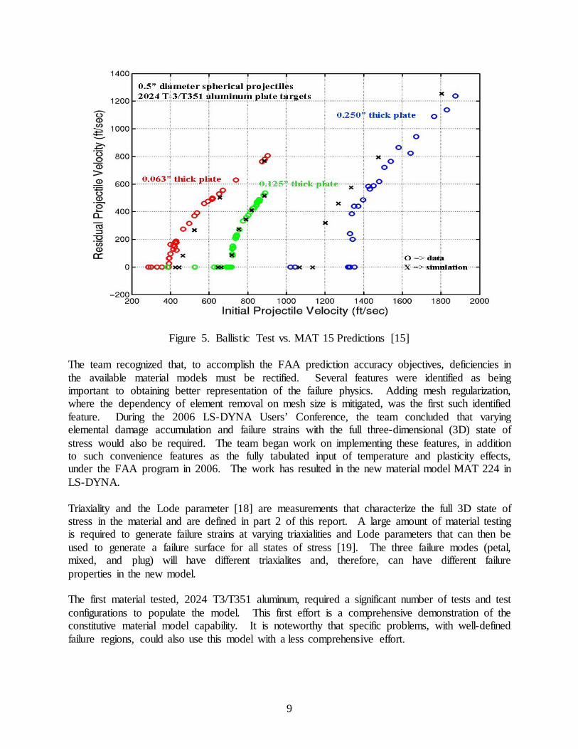
Figure 5. Ballistic Test vs. MAT 15 Predictions [15] The team recognized that, to accomplish the FAA prediction accuracy objectives, deficiencies in the available material models must be rectified. Several features were identified as being important to obtaining better representation of the failure physics. Adding mesh regularization, where the dependency of element removal on mesh size is mitigated, was the first such identified feature. During the 2006 LS-DYNA Users’ Conference, the team concluded that varying elemental damage accumulation and failure strains with the full three-dimensional (3D) state of stress would also be required. The team began work on implementing these features, in addition to such convenience features as the fully tabulated input of temperature and plasticity effects, under the FAA program in 2006. The work has resulted in the new material model MAT 224 in LS-DYNA. Triaxiality and the Lode parameter [18] are measurements that characterize the full 3D state of stress in the material and are defined in part 2 of this report. A large amount of material testing is required to generate failure strains at varying triaxialities and Lode parameters that can then be used to generate a failure surface for all states of stress [19]. The three failure modes (petal, mixed, and plug) will have different triaxialites and, therefore, can have different failure properties in the new model. The first material tested, 2024 T3/T351 aluminum, required a significant number of tests and test configurations to populate the model. This first effort is a comprehensive demonstration of the constitutive material model capability. It is noteworthy that specific problems, with well-defined failure regions, could also use this model with a less comprehensive effort.
9

2.2.2 2024 T3/T351 Aluminum Input Parameters for MAT 224.
An important difference between MAT 224 and the original J-C model is its ability to predict the transition between failure modes. Figure 6 plots the failure plastic strain for two J-C formulations tuned for petaling and plugging failures versus triaxiality (green), and also the initial estimate used in the tabular MAT 224 (red). The plots show that the petaling failure occurs at a higher plastic strain than the plugging failure and that the J-C material model can be tuned to predict either failure, but not both. However, the MAT 224 can match both failures by tracking failure strain versus triaxiality, based on actual material test data.
Figure 6. Triaxiality vs. Failure Plastic Strain Comparison of MAT 224 and J-C Models As the test data set was built and more failure strains were included in the model, the complexity of the failure surface evolved into a 3D contour plot of the effective plastic strain versus triaxiality and Lode parameters. A series of splines between known test points was used to generate the surface. The test points and generated failure surface for 2024 T3/T351 aluminum were developed (shown in figure 7), and are explained in detail in part 2 of this report. The status of the new material model was presented as the keynote address of the 2010 LS-DYNA Users Conference, announcing that the model had been coded into LS-DYNA and was available for beta testing [19]. The code has since completed LS-DYNA QA checks and is now a production material model in LS-DYNA. Currently, the yield surface in MAT 224 is based on von Mises’ J2 flow theory. The material model is being enhanced by including an option of a generalized yield surface based on J3 flow, which will allow the modeling of tensile and compressive yield stress asymmetry.
tabular
10
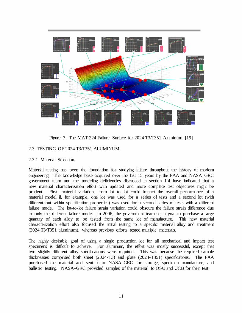
Figure 7. The MAT 224 Failure Surface for 2024 T3/T351 Aluminum [19] 2.3 TESTING OF 2024 T3/T351 ALUMINUM. 2.3.1 Material Selection.
Material testing has been the foundation for studying failure throughout the history of modern engineering. The knowledge base acquired over the last 15 years by the FAA and NASA–GRC government team and the modeling deficiencies discussed in section 1.4 have indicated that a new material characterization effort with updated and more complete test objectives might be prudent. First, material variations from lot to lot could impact the overall performance of a material model if, for example, one lot was used for a series of tests and a second lot (with different but within specification properties) was used for a second series of tests with a different failure mode. The lot-to-lot failure strain variation could obscure the failure strain difference due to only the different failure mode. In 2006, the government team set a goal to purchase a large quantity of each alloy to be tested from the same lot of manufacture. This new material characterization effort also focused the initial testing to a specific material alloy and treatment (2024 T3/T351 aluminum), whereas previous efforts tested multiple materials. The highly desirable goal of using a single production lot for all mechanical and impact test specimens is difficult to achieve. For aluminum, the effort was mostly successful, except that two slightly different alloy specifications were required. This was because the required sample thicknesses comprised both sheet (2024-T3) and plate (2024-T351) specifications. The FAA purchased the material and sent it to NASA–GRC for storage, specimen manufacture, and ballistic testing. NASA–GRC provided samples of the material to OSU and UCB for their test
11

programs. The OSU material characterization tests were primarily conducted on one manufacturing lot of 0.5-inch 2024 aluminum T351 plate (material specification sheets are contained in part 3 of this report). Plates from the same manufacturing lot were used for the NASA–GRC model validation impact tests. 2.3.2 Material Characterization Testing.
The OSU test program comprised a significant number of tests to define the material behavior at varying strain rates and temperatures and to populate the yield and failure surfaces. Figure 8 shows the various specimens and geometries that made up the initial plastic deformation material model data set and their orientation in the plate material. Varying these orientations allowed the material to be assessed for isotropy. The testing has covered failures over a range of triaxialities and Lode parameters and built a comprehensive map to generate the 3D failure surface, as shown in figure 7.
Figure 8. Test Specimen Machining
The test program needed to cover a wide range of temperatures and strain rates. Quasistatic tests at a range of temperatures were performed in servohydraulic test machines. High strain rate tests were performed in tension, torsion, and compression using split Hopkinson bars. Testing data acquisition included loading, strain gage measurements from the split Hopkinson bar, strain gage information on the specimens themselves, and digital image correlation (DIC), whenever possible. Early in the testing, it was noted that the strain gage and DIC results matched well and that the DIC was more useful than the specimen strain gage. Use of the DIC allows direct comparison between the test and analysis of the complete region of strain and strain values over a much larger range.
X
Rolled Direction
Transverse Direction
Tension Specimens
0 °
90 ° 45 °
- 45 °
Torsion Specimen
Compression Specimens
0 ° - 45 °
45 ° Through
Thickness
Thickness Direction
Y
Z
90 °
12

Figure 9 shows the tensile test data force/displacement curves and figure 10 shows the DIC image just prior to failure for plane stress specimens with different geometries, which corresponds to different triaxialities (as noted previously in this section, triaxiality and Lode parameter are defined in part 2 of this report). A careful analysis was performed on all of the testing to check triaxialites and Lode parameters and to ensure correct generation of the failure surface.
Figure 9. Tensile Test Force Displacement Curve
0.00 0.20 0.40 0.60 0.80 1.00Displacement (mm)
0
200
400
600
800
1000
1200
1400Lo
ad [N
]
Plane Stress SpecimensSG1 (Smooth)SG2 (3/16 in Radius)SG3 (5/64 in Radius)SG4 (1/64 in Radius)
13

Figure 10. The DIC Image Just Prior to Failure for Tension Specimens With Different Size Notches
The mechanical property test program has developed a large, complete, and unique data set that is planned to be made available through NASA–GRC. Handling this large amount of data is a challenge and work on making the data accessible is ongoing. 2.3.3 Impact Testing.
In addition to the mechanical property testing, impact testing was conducted by NASA–GRC and UCB on the same manufacturing lot of 2024 T3/T351 aluminum that had been used in the OSU material characterization tests. The impact test results are reported in references 1 and 2, and the model validation using these tests is reported in part 2 of this report. One goal of this program is to produce the analytical capability to predict the results of the impact tests based on the mechanical property tests alone, without post-impact test correlation. The program has succeeded in creating this capability, as documented in part 2. 2.3.3.1 NASA Impact Testing.
Using the example of the impact testing conducted at NASA–GRC, this section presents some details on one phase of those tests. In this test phase, cylindrical projectiles were impacted against flat plates using a gas gun connected to a vacuum chamber, shown in figure 11. The gun barrel had a length of 12 ft and a bore of 2.0 in. The projectile was carried down the gun barrel supported by rigid foam in a cylindrical polycarbonate sabot. The gun barrel protruded into the vacuum chamber that held the fixture for the specimens. The sabot was stopped at the end of the
SG1 SG2
SG3 SG4
14

gun barrel by a stopper block which had a hole in the front large enough to allow the projectile to pass through. This stopper system was designed so that the bottom of the sabot, including the O-rings, remained in the gun barrel and formed a seal that prevented the gas pressure behind the sabot from affecting the pressure in the vacuum chamber.
Figure 11. Large NASA Gas Gun With Vacuum Chamber For the 2024 T3/T351 aluminum, 1/8-, 1/4-, and 1/2-inch-thick flat panel targets were tested in two separate test programs. In the first program, a projectile was defined and was used for all three thickness materials. The tests resulted in significant failure mode and ballistic limit differences as the material became thicker. This series of tests produced some values for penetration velocity well above those expected during an engine failure, which raised the question as to if the failure mode observed in those tests was representative of the rare aircraft threat defined in reference 7. Reference 7 shows that many of the damaging fragments of interest have the potential to travel between 600 to 900 ft/sec. To eliminate any speed range effects on the failure mode, a second round of testing was performed with all of the impacts in the speed range of interest. To achieve this, the projectile mass was increased as the target material thickness was increased. Examples of ballistic limit test specimens are shown in figure 2. The figure shows a 0.063-inch-thick panel, a 0.125-inch-thick panel, and a 0.25-inch-thick panel, all three of which were tested at an impact speed where penetration occurred. In the thicker panel, the damage is in the form of a shear plug, with minimal overall plastic deformation near the impact site. In the thinner panels, the failure mode is somewhat different, involving significant plastic deformation and radial cracking, as well as apparent tensile failure initiating on the back side of the panel. To be truly predictive, it is necessary that impact failure models be able to predict different failure modes, such as those shown in the figure. A series of tests was performed to bound the speed of penetration. The limit is usually given as a single value but, in reality, impacts near the limit will have a probability of penetration. Results from the test program can be seen in figure 12 [20],
15

which shows the transition between penetrated and nonpenetrated tests for three different thickness panels in the range of 600-900 ft/sec, as well as some uncertainty in the probability of penetration in the transition zone. Each point shows the test impact velocity, with solid symbols representing tests in which the projectile penetrated the panel and open symbols representing tests in which penetration did not occur.
Figure 12. Ballistic Test Results Using Cylindrical Projectiles on AL2024 Panels With Thicknesses of 0.125 Inch, 0.25 Inch, and 0.5 Inch
3. SUMMARY.
National Aeronautics and Space Administration-Glenn Research Center (NASA–GRC) and the Federal Aviation Administration (FAA) have had a strong collaboration in impact testing and analysis and continue to work closely on developing metals impact technology and the LS-DYNA Aerospace Working Group. A bottom-up approach has been used to address difficult challenges in aircraft safety. The success reported here is the work of a large team, where NASA and the FAA each share the responsibility for the funding and advancement of the impact modeling capability. It has been a productive and rewarding process that is delivering sought-after products to the user community. The program continues to produce additional extensive mechanical property test data for other metal alloys; these data are needed for the specific input parameters used with the J-C MAT 224 material model. The testing and analysis required to produce these material models for aircraft metals is based on the work done on the 2024 T3/T351 aluminum. Titanium 6Al-4V and Inconel 718 are the next two metal alloys to be characterized.
16

4. REFERENCES.
1. Pereira, J.M., Revilock, D.M., Lerch, B.A., and Ruggeri, C.R., “Impact Testing of Aluminum 2024 and Titanium 6Al-4V for Material Model Development,” FAA report DOT/FAA/TC-12/58, May 2013.
2. Johnson, G., Carreon, B., DeVera, G., Iyler, J., Kostka, T., and Mseis, G., “Impact
Characteristics of 2024 Aluminum Subject to Penetration by Cylindrical Projectiles,” FAA report DOT/FAA/TC-12/16, April 2013.
3. LS-DYNA AWG website, http://awg.lstc.com, accessed December 19, 2013. 4. Rice, R.C., Jackson, J.L., Bakuckas, J., and Thompson, S., “Metallic Materials Properties
Development and Standardization (MMPDS),” FAA report DOT/FAA/AR-MMPDS-01, January 2003.
5. Mathis, J.A., “Design Procedures and Analysis of Turbine Rotor Fragment Hazard
Containment,” FAA report DOT/FAA/AR-96/121, March 1997. 6. Frankenberger, C.E. III, “Small-Engine Uncontained Debris Analysis,” FAA report
DOT/FAA/AR-99/7, February 1999. 7. Frankenberger, C.E., “Large Engine Uncontained Debris Analysis,” FAA report
DOT/FAA/AR-99/11, May 1999. 8. Seng S., Manion J., and Frankenberger, C., “Uncontained Engine Debris Analysis Using
the Uncontained Engine Debris Damage Assessment Model,” FAA report DOT/FAA/AR-04/16, September 2004.
9. Gogolowski, R.P. and Morgan, B.R., “Ballistic Experiments With Titanium and
Aluminum Targets,” FAA report DOT/FAA/AR-01/21, April 2001. 10. Lundin S.J., “Engine Debris Fuselage Penetration Testing, Phase I,” FAA report
DOT/FAA/AR-01/27-I, August 2001. 11. Lundin, S.J., “Engine Debris Fuselage Penetration Testing, Phase II,” FAA report
DOT/FAA/AR-01/27-II, September 2002. 12. Lundin, S.J. and Mueller, R.B., “Advanced Aircraft Materials, Engine Penetration
Testing,” FAA report DOT/FAA/AR-03/37, December 2005. 13. Kelly, S. and Johnson, G., “Statistical Testing of Aircraft Materials for Transport-
Airplane Rotor Burst Fragment Shielding,” FAA report DOT/FAA/AR-06/9, May 2006. 14. Lesuer, D.R., “Experimental Investigations of Material Models for Ti-6AI-4V Titanium
and 2024-T3 Aluminum,” FAA report DOT/FAA/AR-00/25, September 2000.
17
15. Kay, G., “Failure Modeling of Titanium 6Al-4V and Aluminum 2024-T3 With the Johnson-Cook Material Model,” FAA report DOT/FAA/AR-03/57, September 2003.
16. Kay, G., Goto, D., and Couch, R., “Statistical Testing and Material Model
Characterization of Aluminum and Titanium for Transport Airplane Rotor Burst Fragment Shielding,” FAA report DOT/FAA/AR-07/26, August 2007.
17. Buyuk, M., Loikkanen, M., and Kan, C.D., “Explicit Finite Element Analysis of
2024-T3/T351 Aluminum Material Under Impact Loading for Airplane Engine Containment and Fragment Shielding,” FAA report DOT/FAA/AR-08/36, September 2008.
18. Carney, K.S., DuBois, P.A., Buyuk, M., and Kan, S., “Generalized, Three Dimensional
Definition, Description, and Derived Limits of the Triaxial Failure Of Metals,” Journal of Aerospace Engineering, 2009.
19. DuBois, Paul A., “Development, Implementation and Validation of a 3-D Failure Model
for Aluminum 2024 for High Speed Impact Applications,” 2010 LS-DYNA Users Conference Keynote Address, June 7, 2010, Dearborn, Michigan.
20. Pereira, J.M., Revilock, D.M., Lerch, B.A., and Ruggieri, C.R., “Impact Testing of
Aluminum 2024 and Titanium 6Al-4V for Material Model Development,” FAA report DOT/FAA/TC-12/58, January 2013.
18