Embed Size (px)
Citation preview

1
An Optimal Algorithm for Relay Node Assignmentin Cooperative Ad Hoc Networks
Sushant Sharma,Student Member, IEEE, Yi Shi, Member, IEEE, Y. Thomas Hou,Senior Member, IEEE,Sastry Kompella,Member, IEEE
Abstract—Recently, cooperative communications, in the formof having each node equipped with a single antenna and exploitspatial diversity via some relay node’s antenna, is shown tobe a promising approach to increase data rates in wirelessnetworks. Under this communication paradigm, the choice ofa relay node (among a set of available relay nodes) is criticalin the overall network performance. In this paper, we study therelay node assignment problem in a cooperative ad hoc networkenvironment, where multiple source-destination pairs competefor the same pool of relay nodes in the network. Our objective isto assign the available relay nodes to different source-destinationpairs so as to maximize the minimum data rate among all pairs.The main contribution of this paper is the development of anoptimal polynomial time algorithm, called ORA, that achievesthis objective. A novel idea in this algorithm is a “linear marking”mechanism, which maintains linear complexity of each iteration.We give a formal proof of optimality for ORA and use numericalresults to demonstrate its capability.
Index Terms—Cooperative communications, relay node assign-ment, achievable rate, ad hoc network, optimization.
I. I NTRODUCTION
SPATIAL diversity, in the form of employing multipletransceiver antennas, is shown to be very effective in
coping fading in wireless channel. However, equipping a wire-less node with multiple antennas may not be practical, as thefootprint of multiple antennas may not fit on a wireless node(particularly on a handheld wireless device). To achieve spatialdiversity without requiring multiple transceiver antennas onthe same node, the so-calledcooperative communications hasbeen introduced [10], [16], [17]. Under cooperative communi-cations, each node is equipped with only a single transceiverand spatial diversity is achieved by exploiting the antenna onanother (cooperative) node in the network.
We consider two categories of cooperative communications,namely, amplify-and-forward (AF) and decode-and-forward(DF) [10]. Under AF, the cooperative relay node amplifies thesignal received from the information source before forwarding
Manuscript received May 26, 2009; revised January 29, 2010 and August23, 2010; approved by IEEE/ACM TRANSACTIONS ONNETWORKING EditorS. Diggavi.
An abridged version of this paper was published in ACM MobiHoc 2008under the title “Optimal Relay Assignment for Cooperative Communications”.
S. Sharma is with the Department of Computer Science, Virginia Poly-technic Institute and State University, Blacksburg, VA 24061 USA (e-mail:[email protected]).
Y. Shi and Y.T. Hou are with the Bradley Department of Electrical andComputer Engineering, Virginia Polytechnic Institute and State University,Blacksburg, VA 24061 USA e-mail: ([email protected]; [email protected]).
S. Kompella is with the Information Technology Division, USNaval Research Laboratory, Washington, DC 20375 USA (e-mail: [email protected]).
it to the destination node. Under DF, the cooperative relaynode decodes the received signal, and re-encodes it beforeforwarding it to the destination node. Regardless of AF orDF, the choice of a relay node plays a critical role in theperformance of cooperative communications [1], [2], [24]. Aswe shall see in Section III, an improperly chosen relay nodemay offer a smaller data rate for a source-destination pair thanthat under direct transmission.
In this paper, we study the relay node assignment problemin a cooperative ad hoc network environment. Specifically,we consider an ad hoc network where there are multipleactive source-destination pairs and the remaining nodes can beexploited as relay nodes. We want to determine the optimalassignment of relay nodes to the source-destination pairs so asto maximize the minimum data rate among all pairs. Althoughsolution to this problem can be found via exhaustive search(among all possible relay node assignments), the complexityis exponential. Our goal in this paper is to find an algorithmwith polynomial-time complexity to solve this problem.
A. Main Contributions
In this paper, we study how to assign a set of relay nodesto a set of source-destination pairs so as to maximize theminimum achievable data rate among all the pairs. The maincontributions of this paper are the following.
• We develop an algorithm, called Optimal Relay Assign-ment (ORA) algorithm, to solve the relay node assign-ment problem. A novel idea in ORA is a “linear marking”mechanism, which is able to offer a linear complexity ateach iteration. Due to this mechanism, ORA is able toachieve polynomial time complexity.
• We offer a formal proof of optimality for the ORAalgorithm. The proof is based on contradiction and hingeson a clever recursive trace-back of source nodes and relaynodes in the solution by ORA and another hypothesizedbetter solution.
• We show a number of nice properties associated withORA. These include: (i) the algorithm works regardlessof whether the number of relay nodes in the network ismore than or less than the number of source-destinationpairs; (ii) the final achievable rate for each source-destination pair is guaranteed to be no less than thatunder direct transmissions; (iii) the algorithm is able tofind the optimal objective regardless of initial relay nodeassignment.

Report Documentation Page Form ApprovedOMB No. 0704-0188
Public reporting burden for the collection of information is estimated to average 1 hour per response, including the time for reviewing instructions, searching existing data sources, gathering andmaintaining the data needed, and completing and reviewing the collection of information. Send comments regarding this burden estimate or any other aspect of this collection of information,including suggestions for reducing this burden, to Washington Headquarters Services, Directorate for Information Operations and Reports, 1215 Jefferson Davis Highway, Suite 1204, ArlingtonVA 22202-4302. Respondents should be aware that notwithstanding any other provision of law, no person shall be subject to a penalty for failing to comply with a collection of information if itdoes not display a currently valid OMB control number.
1. REPORT DATE 23 AUG 2010 2. REPORT TYPE
3. DATES COVERED 00-00-2010 to 00-00-2010
4. TITLE AND SUBTITLE An Optimal Algorithm for Relay Node Assignment in Cooperative AdHoc Networks
5a. CONTRACT NUMBER
5b. GRANT NUMBER
5c. PROGRAM ELEMENT NUMBER
6. AUTHOR(S) 5d. PROJECT NUMBER
5e. TASK NUMBER
5f. WORK UNIT NUMBER
7. PERFORMING ORGANIZATION NAME(S) AND ADDRESS(ES) Naval Research Laboratory,Information Technology Division,Washington,DC,20375
8. PERFORMING ORGANIZATIONREPORT NUMBER
9. SPONSORING/MONITORING AGENCY NAME(S) AND ADDRESS(ES) 10. SPONSOR/MONITOR’S ACRONYM(S)
11. SPONSOR/MONITOR’S REPORT NUMBER(S)
12. DISTRIBUTION/AVAILABILITY STATEMENT Approved for public release; distribution unlimited
13. SUPPLEMENTARY NOTES to appear in IEEE/ACM Transactions on Networking, Issue to be determined
14. ABSTRACT Recently, cooperative communications, in the form of having each node equipped with a single antennaand exploit spatial diversity via some relay node?s antenna, is shown to be a promising approach toincrease data rates in wireless networks. Under this communication paradigm, the choice of a relay node(among a set of available relay nodes) is critical in the overall network performance. In this paper, westudy the relay node assignment problem in a cooperative ad hoc network environment, where multiplesource-destination pairs compete for the same pool of relay nodes in the network. Our objective is to assignthe available relay nodes to different source-destination pairs so as to maximize the minimum data rateamong all pairs. The main contribution of this paper is the development of an optimal polynomial timealgorithm, called ORA, that achieves this objective. A novel idea in this algorithm is a ?linear marking?mechanism, which maintains linear complexity of each iteration. We give a formal proof of optimality forORA and use numerical results to demonstrate its capability.
15. SUBJECT TERMS
16. SECURITY CLASSIFICATION OF: 17. LIMITATION OF ABSTRACT Same as
Report (SAR)
18. NUMBEROF PAGES
14
19a. NAME OFRESPONSIBLE PERSON
a. REPORT unclassified
b. ABSTRACT unclassified
c. THIS PAGE unclassified
Standard Form 298 (Rev. 8-98) Prescribed by ANSI Std Z39-18

2
• We provide a sketch of a possible implementation of theORA algorithm. Some practical issues and overhead inthe implementation are discussed.
B. Paper Organization
In Section II, we discuss related work and contrast themwith this paper. Section III gives a brief overview of coopera-tive communications, so as to set the context of our study. InSection IV, we describe the relay node assignment problemin a cooperative ad hoc network environment. Section Vpresents our ORA algorithm. In Section VI, we give a proofof optimality for ORA. Section VII presents numerical results,and Section VIII presents a sketch of how ORA can beimplemented. Section IX concludes this paper.
II. RELATED WORK
The concept of cooperative communications can be tracedback to the three-terminal communication channel (or a relaychannel) in [20] by Van Der Meulen. Shortly after, Cover andEl Gamal studied the general relay channel and established anachievable lower bound for data transmission [4]. These twoseminal works laid down the foundation for the present-dayresearch on cooperative communications that can be broadlyclassified into the following three categories.
(a) Physical Layer Schemes. Current research on CC aimsto exploit distributed antennas on other nodes in the network.This has resulted in several protocols at the physical layer [5],[7], [8], [10], [14], [16], [17]. These protocols describe variousways through which nodes can cooperate at the physical layer.
In [10], Lanemanet al. studied the mutual informationbetween a pair of nodes using a third cooperating nodeunder the so-called fixed relaying schemes (AF or DF). Theunderlying physical layer model for CC in this paper is basedon these two schemes. In addition to fixed relaying schemes,the authors also presented selection relaying, in which nodescan switch between AF or DF (depending on instantaneouschannel conditions), and incremental relaying, which utilizeslimited feedback from the receiving node to further improvethe performance of CC.
In [7], Gunduz and Erkip studied an opportunistic coopera-tion scheme in which a feedback channel among cooperatingnodes can be used to share channel state information andhelp perform power control. The authors showed that theperformance of DF improves when power control is employed.This kind of opportunistic DF is an alternative to the physicallayer fixed DF considered in our work.
Another alternative physical layer scheme could be thedelay-tolerant DF presented in [5]. In this delay-tolerant DFscheme, distributed space-time codes are used to address theissue of asynchrony (transmission delay) among cooperativetransmitters.
Additionally, in [8] and [14], authors studied multi-hopcooperative protocols that involve cooperation among multipletransmitting nodes along the path. In [16] and [17], theauthors performed an in-depth study on the practical issuesof implementing user cooperation in a conventional CDMAsystem.
(b) Network Layer Schemes for Multi-hop Networks.Recent efforts on CC at the network layer include [9], [15],[22]. In [9], Khandaniet al. studied minimum energy routingproblem (for a single message) by exploiting both wirelessbroadcast advantage and CC. However, their proposed solu-tions cannot provide any performance guarantee for generalad hoc networks. In [22], Yeh and Berry aimed to generalizethe well known maximum differential backlog policy [18] inthe context of CC. They formulated a challenging nonlinearprogram with exponential number of variables that character-izes the network stability region, but only provided solutionsfor a few simple network topologies. In [15], Scaglioneet al.proposed two architectures for multi-hop cooperative wirelessnetworks. Under these architectures, nodes in the networkcan form multiple cooperative clusters. They showed thatthe network connectivity can be improved by using suchcooperative clusters. However, problems related with optimalrouting and relay node assignment were not discussed in theirwork.(c) Relay Node Assignment for Ad hoc Networks. Themost relevant research to our work (i.e. relay node assignment)include [1], [2], [13], [21], [24]. In [24], Zhaoet al. showedthat for a single source-destination pair, in the presence ofmultiple relay nodes, it is sufficient to choose one “best”relay node, instead of multiple relay nodes. This result isinteresting, as it paves the way for research on assigning nomore than one relay node to a source-destination pair, whichis the setting that we have adopted in this paper. In [21],Wang et al. showed how game theory can be used by asingle session to select the best cooperative relay node. In [1],Bletsaset al. proposed a distributed scheme for relay nodeselection based on the instantaneous channel conditions at therelay node. In contrast to [1], [21], and [24], our paper isnot limited to a single-session, and considers the relay nodeassignment for multiple competing sessions with the goal ofmaximizing the minimum data rate among all of them. In [13],Ng and Yu studied an important utility maximization problemfor the joint optimization of relay node selection, cooperativecommunications, and resource allocation in a cellular network.However, their solution procedure has non-polynomial runningtime. In [2], Caiet al. studied relay node selection and powerallocation for AF-based wireless relay networks, and proposeda heuristic solution. Additionally, both [2] and [13] havedifferent objectives from our work.
III. C OOPERATIVECOMMUNICATIONS: A PRIMER
The essence of cooperative communications is best ex-plained by a three-node example in Fig. 1. In this figure, nodes is the source node, noded is the destination node, and noder is a relay node. Transmission froms to d is done on a frame-by-frame basis. Within a frame, there are two time slots. Inthe first time slot, source nodes makes a transmission to thedestination noded. Due to the broadcast nature of wirelesscommunications, this transmission is also overheard by therelay noder. In the second time slot, noder forwards thedata received in the first time slot to noded. Note that such atwo-slot structure is necessary for cooperative communicationsdue to the half-duplex nature of most wireless transceivers.

3
r
s
d
Fig. 1. A three-node schematic for cooperative communication.
In this section, we give expressions for achievable data rateunder cooperative communications and direct transmissions(i.e., no cooperation). For cooperative communications, weconsider both amplify-and-forward (AF) and decoded-and-forward (DF) modes [10].
Amplify-and-Forward (AF) Under this mode, lethsd, hsr,hrd capture the effects of path-loss, shadowing, and fadingbetween nodess and d, s and r, and r and d, respectively.Denotezd[1] and zd[2] the zero-mean background noise atnoded in the first time slot and second time slot, respectively,both with varianceσ2
d. Denotezr[1] the zero-mean backgroundnoise at noder in the first time slot, with varianceσ2
r .Denotexs the signal transmitted by source nodes in the
first time slot. Then the received signal at destination noded,ysd, can be expressed as
ysd = hsdxs + zd[1] , (1)
and the received signal at the relay noder, ysr, is
ysr = hsrxs + zr[1] . (2)
In the second time slot, relay noder transmits to destinationnoded. The received signal atd, yrd, can be expressed as
yrd = hrd · αr · ysr + zd[2] ,
whereαr is the amplifying factor at relay noder andysr isgiven in (2). Thus, we have
yrd = hrdαr · (hsrxs + zr[1]) + zd[2] . (3)
The amplifying factorαr at relay noder should satisfy powerconstraintα2
r(|hsr |2Ps + σ2
r) = Pr, wherePs andPr are thetransmission powers at nodess andr, respectively. So,αr isgiven by
α2r =
Pr
|hsr|2Ps + σ2r
.
We can re-write (1), (2) and (3) into the following compactmatrix form
Y = Hxs +BZ ,
where
Y =
[
ysdyrd
]
, H =
[
hsdαrhrdhsr
]
,
B =
[
0 1 0αrhrd 0 1
]
, and Z =
zr[1]zd[1]zd[2]
. (4)
It has been shown in [10] that the above channel, whichcombines both direct path (s to d) and relay path (s to r to d),can be modeled as a one-input, two-output complex Gaussian
noise channel. The achievable data rateCAF(s, r, d) from s tod can be given by
CAF(s, r, d) =W
2log2[det(I+(PsHH
†)(BE[ZZ†]B†)−1)] ,
(5)whereW is the bandwidth,det(·) is the determinant function,I is the identity matrix, the superscript “†” represents thecomplex conjugate transposition, andE[·] is the expectationfunction.
After putting (4) into (5) and performing algebraic ma-
nipulations, we haveCAF(s, r, d) =W
2log
(
1 +Ps
σ2d
|hsd|2
+Ps|hsr|2Pr|hrd|2
Psσ2d|hsr|
2 + Prσ2r |hrd|
2 + σ2rσ
2d
)
. Denote SNRsd =
Ps
σ2
d
|hsd|2, SNRsr = Ps
σ2r
|hsr|2, and SNRrd = Pr
σ2
d
|hrd|2. We
have
CAF(s, r, d) =W · IAF(SNRsd,SNRsr,SNRrd) , (6)
where IAF(SNRsd,SNRsr,SNRrd) = 12 log2
(
1 + SNRsd
+ SNRsr·SNRrd
SNRsr+SNRrd+1
)
.
Decode-and-Forward (DF) Under this mode, relay noderdecodes and estimates the received signal from source nodes
in the first time slot, and then transmits the estimated data todestination noded in the second time slot. The achievable datarate for DF under the two time-slot structure is given by [10]as
CDF(s, r, d) =W · IDF(SNRsd,SNRsr,SNRrd) , (7)
where
IDF(SNRsd,SNRsr,SNRrd) =1
2min{log2(1 + SNRsr),
log2(1 + SNRsd + SNRrd)}. (8)
Note thatIAF(·) and IDF(·) are increasing functions ofPsandPr , respectively. This suggests that, in order to achieve themaximum data rate under either mode, both source node andrelay node should transmit at maximum power. In this paper,we letPs = Pr = P .Direct Transmission When cooperative communications(i.e., relay node) is not used, source nodes transmits todestination noded in both time slots. The achievable data ratefrom nodes to noded is
CD(s, d) = W log2(1 + SNRsd) .
Based on the above results, we have two observations.First, comparingCAF (or CDF) to CD, it is hard to say thatcooperative communications is always better than the directtransmission. In fact, a poor choice of relay node could makethe achievable data rate under cooperative communications tobe lower than that under direct transmission. This fact under-lines the significance of relay node selection in cooperativecommunications. Second, although AF and DF are differentmechanisms, the capacities for both of them have the sameform, i.e., a function of SNRsd, SNRsr, and SNRrd. Therefore,a relay node assignment algorithm designed for AF is alsoapplicable for DF. In this paper, we develop a relay nodeassignment algorithm for both AF and DF. Table I lists thenotation used in this paper.

4
TABLE INOTATION
Symbol DefinitionCR(si, rj) Achievable rate forsi-di pair when relay noderj is
usedCR(si, ∅) Achievable rate forsi-di pair under direct transmissionCmin The minimum rate among all source-destination
pairshuv Effect of path-loss, shadowing, and fading from node
u to nodevNs Set of source nodes in the networkNr Set of relay nodes in the networkNs = |Ns|, number of source nodes in the networkNr = |Nr|, number of relay nodes in the networkN Number of all the nodes in the networkP Maximum transmission powerrj The j-th relay node,rj ∈ Nr
Rψ(si) The relay node assigned tosi underψsi The i-th source node,si ∈ Ns
Sψ(rj) The source node that usesrj underψSNRuv The signal noise ratio between nodesu and vW Channel bandwidthxs Signal transmitted by nodesyuv Received signal at nodev (form nodeu)zv[t] Background noise at nodev during time slottαr Amplifying factor at relayrσ2v Variance of background noise at nodevψ A solution for relay node assignment
IV. T HE RELAY NODE ASSIGNMENT PROBLEM
Based on the background in the last section, we considerrelay node assignment problem in a network setting. Thereare N nodes in an ad hoc network, with each node beingeither a source node, a destination node, or a potential relaynode (see Fig. 2). In order to avoid interference, we assumethat orthogonal channels are available in the network (e.g.,using OFDMA), which is proposed for cooperative communi-cations [10]. The channel gain from nodeu to v is captured byvariablehuv. DenoteNs = {s1, s2, · · · , sNs
} the set of sourcenodes,Nd = {d1, d2, · · · , dNd
} the set of destination nodes,andNr = {r1, r2, · · · , rNr
} the set of relays (see Fig. 2). Weconsider unicast transmission where every source nodesi ispaired with a destination nodedi, i.e., Nd = Ns. We alsoconsider that each node is equipped with a single transceiverand can transmit/receive within one channel at a time. Weassume that each node can only serve a unique role of source,destination, or relay. That is,Nr = N − 2Ns. Further, weassume that a session utilizes one relay node for CC [24].
Note that a source node may not always get a relay node.There are two possible scenarios in which this may happen.First, there may not be sufficient number of relay nodes in thenetwork (e.g.,Nr < Ns). In this case, some source nodes willnot have relay nodes. Second, even if there are enough relaynodes, a sender may choose not to use a relay node if it leadsto a lower data rate than direct transmission (see discussion atthe end of Section III).
We now discuss the objective function of our problem.Although different objectives can be used, a widely-usedobjective for CC is to increase the achievable data rate ofindividual sessions. For the multi-session network environmentconsidered in this paper (see Fig. 2), each source-destinationpair will have a different achievable data rate after we applya relay node assignment algorithm. So, a plausible objectiveis to maximize the minimum data rate among all the source-
Sender Receiver Potential Relay Node
Fig. 2. A cooperative ad hoc network consisting of source nodes, destinationnodes, and relay nodes.
destination pairs.More formally, denoteR(si) the relay node assigned tosi,
andS(rj) as the source node that usesrj . For both AF andDF, the achievable data rate of the session can be written as(see Section III)
WIR(SNRsi,di,SNRsi,R(si),SNRR(si),di) ,
with IR(·) = IAF(·) when AF is employed, andIR(·) = IDF(·)when DF is employed. In casesi does not use a relay, wedenoteR(si) = ∅, and the data rate is the achievable rateunder direct transmission, i.e.,
CR(si, ∅) = CD(si, di) .
Combining both these cases, we have
CR(si,R(si)) =
WIR(SNRsi,di ,SNRsi,R(si),
SNRR(si),di) if R(si) 6= ∅W log(1 + SNRsi,di) if R(si) = ∅
(9)
Note that we do not listdi in functionCR(si,R(si)) since foreach source nodesi, the corresponding destination nodedi isdeterministic.
DenoteCmin as our objective function, which is the mini-mum rate among all source nodes. That is,
Cmin = min{CR(si,R(si)) : si ∈ Ns}.
Our objective is to find an optimal relay node assignment forall the source-destination pairs such thatCmin is maximized.
In subsequent sections, we present a polynomial time so-lution to the relay node assignment problem along with acorrectness proof.
V. A N OPTIMAL RELAY ASSIGNMENT ALGORITHM
A. Basic Idea
The optimal polynomial-time algorithm we will present iscalled Optimal Relay Assignment (ORA) algorithm. Figure 3shows the flow chart of the ORA algorithm.
Initially, the ORA algorithm starts with a random butfeasible relay node assignment. By feasible, we mean thateach source-destination pair can be assigned at most one relaynode and that a relay node can be assigned only once. Suchinitial feasible assignment is easy to construct, e.g., directtransmission between each source-destination pair (without theuse of a relay) is a special case of feasible assignment.
Starting with this initial assignment, ORA adjusts the as-signment during each iteration, with the goal of increasingthe objective functionCmin. Specifically, during each iteration,ORA identifies the source node that corresponds toCmin.
5
BEGIN
Better solution found.
NO
YES NO
Preprocessing, andInitial relay assignment
Can we finda better solution?
YES
NO
Start the search
ReturnYES
ReturnNO
END
YES
Mark this relay, and denoteits corresponding source as s
BEGIN
Find_Another_Relay(s )
YES
NO
Is this relay already assigned?
Can we find anunmarked relay for s with data rate larger
than Cmin?
For s , use Find_Another_Relay(s ) to
determine if another relay can be
assigned
Identify the source swith minimum data rate Cmin.
b
i
Clear marks on all relays.
Use Find_Another_Relay(s ) toimprove the data rate of s ,
and return the outcome.b
b
i
j
j
j
Fig. 3. A flow chart of the ORA algorithm.
Then, ORA helps this source node to search a better relaysuch that this “bottleneck” data rate can be increased. In thecase that the selected relay is already assigned to anothersource node, further adjustment of relay node for that sourcenode is necessary (so that its current relay can be released).Such adjustment may have a chain effect on a number ofsource nodes in the network. It is important that for anyadjustment made on a relay node, the affected source nodeshould still maintain a data rate larger thanCmin. There areonly two outcomes from such search in an iteration: (i) a betterassignment is found, in which case, ORA moves on to the nextiteration; or (ii) a better assignment cannot be found, in whichcase, ORA terminates.
There are two key technical challenges we aim to addressin the design. First, for any non-optimal solution, the algo-rithm should be able to find a better solution. As a result,upon termination, the final assignment is optimal. Second,its running time must be polynomial. We will show that
s
cannot f indanother relay
3
s4r4s
2r2
6
r1
r3 5 5 6
7
cannot f indanother relay
can be assigned to
1
r r
r
s s s
6s
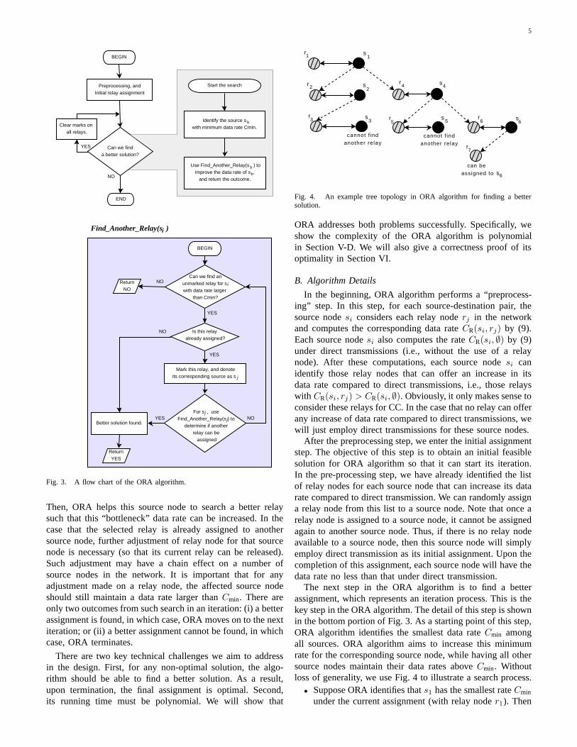
Fig. 4. An example tree topology in ORA algorithm for finding a bettersolution.
ORA addresses both problems successfully. Specifically, weshow the complexity of the ORA algorithm is polynomialin Section V-D. We will also give a correctness proof of itsoptimality in Section VI.
B. Algorithm Details
In the beginning, ORA algorithm performs a “preprocess-ing” step. In this step, for each source-destination pair, thesource nodesi considers each relay noderj in the networkand computes the corresponding data rateCR(si, rj) by (9).Each source nodesi also computes the rateCR(si, ∅) by (9)under direct transmissions (i.e., without the use of a relaynode). After these computations, each source nodesi canidentify those relay nodes that can offer an increase in itsdata rate compared to direct transmissions, i.e., those relayswith CR(si, rj) > CR(si, ∅). Obviously, it only makes sense toconsider these relays for CC. In the case that no relay can offerany increase of data rate compared to direct transmissions, wewill just employ direct transmissions for these source nodes.
After the preprocessing step, we enter the initial assignmentstep. The objective of this step is to obtain an initial feasiblesolution for ORA algorithm so that it can start its iteration.In the pre-processing step, we have already identified the listof relay nodes for each source node that can increase its datarate compared to direct transmission. We can randomly assigna relay node from this list to a source node. Note that once arelay node is assigned to a source node, it cannot be assignedagain to another source node. Thus, if there is no relay nodeavailable to a source node, then this source node will simplyemploy direct transmission as its initial assignment. Upon thecompletion of this assignment, each source node will have thedata rate no less than that under direct transmission.
The next step in the ORA algorithm is to find a betterassignment, which represents an iteration process. This is thekey step in the ORA algorithm. The detail of this step is shownin the bottom portion of Fig. 3. As a starting point of this step,ORA algorithm identifies the smallest data rateCmin amongall sources. ORA algorithm aims to increase this minimumrate for the corresponding source node, while having all othersource nodes maintain their data rates aboveCmin. Withoutloss of generality, we use Fig. 4 to illustrate a search process.
• Suppose ORA identifies thats1 has the smallest rateCmin
under the current assignment (with relay noder1). Then

6
s1 examines other relays with a rate larger thanCmin. If itcannot find such a relay, then no better solution is foundand the ORA algorithm terminates.In case of a tie, i.e., when two or more source nodes havethe same smallest data rate, the tie is broken by choosingthe source node with the highest node index.
• Otherwise, i.e., if there are better relays, we considerthese relays in thenon-increasing order in terms of datarate (should it be assigned tos1). That is, we try the relaythat can offer the maximum possible increase in data ratefirst. In case of a tie, i.e., when two or more relay nodesoffer the same maximum data rate, the tie is broken bychoosing the relay node with the highest node index.
• Suppose that source nodes1 considers relay noder2. Ifthis relay node is not yet assigned to any other sourcenode, thenr2 can be immediately assigned tos1. In thissimple case, we find a better solution and the currentiteration is completed.
• Otherwise, i.e.,r2 is already assigned to a source node,says2, we markr2 to indicate thatr2 is “under consid-eration” and check whetherr2 can be released bys2.
• To releaser2, source nodes2 needs to find another relay(or use direct transmission) while making sure that suchnew assignment still has its data rate larger thanCmin.This process is identical to what we have done fors1,with the only (but important) difference thats2 will notconsider a relay that has already been “marked”, as thatrelay node has already been considered by a source nodeencountered earlier in the search process of this iteration.
• Suppose that source nodes2 now considers relayr3. Ifthis relay node is not yet assigned to any source node,thenr3 can be assigned tos2; r2 can be assigned tos1;and the current iteration is completed. Moreover, if therelay under consideration bys2 is the one that is beingused by the source node that initiated the iteration, i.e.,relay r1, then it is easy to see thatr1 can be taken awayfrom s1. A better solution, wherer1 is assigned tos2,andr2 is assigned tos1, is found and the current iterationis completed. Otherwise, we markr3 and check furtherto see whetherr3 can be released by its correspondingsource node, says3. We also note thats2 can considerdirect transmission if it offers a data rate larger thanCmin.
• Suppose thats3 cannot find any “unmarked” relay thatoffers a data rate larger thanCmin, and its data rate underdirect transmission is no more thanCmin. Thens2 cannotuser3 as its relay.
• If any “unmarked” relay that offers a data rate largerthanCmin cannot be assigned tos2, thens1 cannot user2 and will move on to consider the next relay on itsnon-increasing rate list, sayr4.
• The search continues, with relay nodes being markedalong the way, until a better solution is found or no bettersolution can be found. For example, in Fig. 4,s6 findsa new relayr7. As a result, we have a new assignment,wherer7 is assigned tos6; r6 is assigned tos4; andr4is assigned tos1.
Note that the “mark” on a relay node will not be cleared
Main algorithm1. Perform preprocessing and an initial relay node assignment.2. Set all the relay nodes in the network as “unmarked”.3. Denotesb the source node withCmin,? the smallest data
rate among all source nodes. The corresponding destinationnode ofsb is db and the corresponding relay node isR(sb).
4. Find Another Relay (sb,R(sb), Cmin).5. If sb finds a better relay, then go to line 2.6. Otherwise, the algorithm terminates.
SubroutinesFind Another Relay(S(rj ), rj , Cmin ):7. For every “unmarked” relayrk with CR(S(rj), rk) > Cmin,
do the following in the non-increasing order ofCR(S(rj), rk).?
8. Run CheckRelay Availability(rk , Cmin).9. If rk is available, then do the following:10. Remove relay noderj ’s assignment toS(rj);11. Assign relay noderk to S(rj).12. Otherwise, continue on to nextrk and go to line8.13. If all relays are unavailable, thenS(rj) cannot find another relay.
Check Relay Availability( rj , Cmin ):14. If rj is not assigned to any source node, thenrj is available.15. If rj = R(sb) or rj = ∅, thenrj is available.16. Otherwise,17. Setrj as “marked”.18. Run FindAnother Relay (S(rj), rj , Cmin).19. If S(rj) can find another relay, thenrj is available.20. Otherwiserj is unavailable.? A tie is broken by choosing the node with the largest node index.
Fig. 5. Pseudocode for the ORA algorithm.
throughout the search process in the same iteration. We callthis the “linear marking” mechanism. These marks will onlybe cleared when the current iteration terminates and beforethe start of the next iteration. A pseudocode for the ORAalgorithm is shown in Fig. 5.
We now use an example to illustrate the operation of theORA algorithm, in particular, its “linear marking” mechanism.Readers who already understood the ORA algorithm can skipthis example.
Example 1: Suppose that there are seven source-destinationpairs and seven relay nodes in the network.
Table II(a) shows the data rate for each source nodesiwhen relay noderj is assigned to it. The symbol∅ indicatesdirect transmission. Also shown in Table II(a) is an initialrelay node assignment, which is indicated by an underscoreon the intersecting row (si) and column (rj). Note that thepreprocessing step before the initial assignment ensures thatthe data rate for each source-destination pair in the initialassignment is no less than that under direct transmission.
Under the initial relay node assignment in Table II(a), sources3 is identified as the bottleneck source nodesb with thesmallest rate ofCmin = 13. Since consideration of relay nodesis performed in the order of non-increasing (from largest tosmallest) data rate for the source node under consideration,r4 is therefore considered fors3. Sincer4 is already assignedto source nodes2, we “mark” r4 now. Now s2 needs to findanother relay. But any other relay (or direct transmission) willresult in a data rate no greater than the current objective valueCmin = 13. This means thatr4 cannot be taken away froms2.Sincer4 does not work out fors3, s3 will then consider thenext relay node that offers the second largest data rate value,i.e., relay noder7. Sincer7 is already assigned to senders4,we “mark” r7 now. Next, ORA algorithm will check to see ifs4 can find another relay. It turns out that none of the relay

7
TABLE IIAN EXAMPLE.
(a) Initial relay node assignment.
∅ r1 r2 r3 r4 r5 r6 r7s1 14 7 24 5 14 15 17 9s2 9 8 10 11 20 10 12 11
→ s3 11 10 13 17 21 8 9 19s4 12 8 9 12 11 10 9 18s5 10 9 18 19 24 9 13 23s6 7 18 12 6 11 11 17 20s7 16 1 9 4 14 19 8 12
(b) Assignment after the first iteration.
∅ r1 r2 r3 r4 r5 r6 r7→ s1 14 7 24 5 14 15 17 9s2 9 8 10 11 20 10 12 11s3 11 10 13 17 21 8 9 19s4 12 8 9 12 11 10 9 18s5 10 9 18 19 24 9 13 23s6 7 18 12 6 11 11 17 20s7 16 1 9 4 14 19 8 12
(c) Assignment after the second iteration.
∅ r1 r2 r3 r4 r5 r6 r7s1 14 7 24 5 14 15 17 9s2 9 8 10 11 20 10 12 11s3 11 10 13 17 21 8 9 19s4 12 8 9 12 11 10 9 18s5 10 9 18 19 24 9 13 23s6 7 18 12 6 11 11 17 20
→ s7 16 1 9 4 14 19 8 12
(d) Final assignment upon termination.
∅ r1 r2 r3 r4 r5 r6 r7s1 14 7 24 5 14 15 17 9s2 9 8 10 11 20 10 12 11
→ s3 11 10 13 17 21 8 9 19s4 12 8 9 12 11 10 9 18s5 10 9 18 19 24 9 13 23s6 7 18 12 6 11 11 17 20s7 16 1 9 4 14 19 8 12
nodes exceptr7 can offer a data rate larger than the currentCmin to s4. As a result,r7 cannot be taken away froms4.Source nodes3 will now check for the relay node that offersnext largest rate, i.e.,r3. Sincer3 is already assigned to senders5, we “mark” r3 now. Next, ORA algorithm checks to see ifs5 can find another relay. Thens5 checks relay nodes in non-increasing order of data rate values. Sincer4 (with largestrate),r7 (with the second largest rate), andr3 (with the thirdlargest rate) are all marked, they will not be considered. Therelay with the fourth largest rate isr2, which offers a rate of18 > Cmin = 13. Moreover,r2 is the relay node assigned tosb = s3. Thus,s5 can chooser2. The new assignment afterthe first iteration is shown in Table II(b). Now the objectivevalue,Cmin, is updated to15, which corresponds tos1. Beforethe second iteration, all markings done in the first iteration arecleared.
In the second iteration, ORA algorithm will identifys1 asthe source node with a minimum data rate in the network.The algorithm will then perform a new search for a betterrelay node for sources1. Similar to the first iteration, theassignments for other source nodes can change during thissearch process, but all assignments should result in data rateslarger than15.
The iteration continues and the final assignment upon ter-mination of ORA algorithm is shown in Table II(d), with the
optimal (maximum) value ofCmin being17.
It should be clear that ORA works regardless of whetherNr ≥ Ns or Nr < Ns. For the latter case, i.e., the number ofrelay nodes in the network is less than the number of sourcenodes, it is only necessary to consider relay node assignmentfor a reduced subset ofNr source nodes, where the data rateof each source in this subset under direct transmission is lessthan the data rate of those(Ns−Nr) source nodes not in thissubset. As a result, in the case ofNs > Nr, ORA will runeven faster due to a smaller problem size.
C. Caveat on the Proposed Marking Mechanism
We now re-visit the marking mechanism in the ORAalgorithm. Although different marking mechanisms may bedesigned to achieve the optimal objective, the algorithmcomplexity under different marking mechanisms may differsignificantly. In this section, we first present a marking mech-anism, which appears to be a natural approach but leads to anexponential complexity for each iteration. Then we discuss ourproposed marking mechanism and show its linear complexityfor each iteration.
A natural approach is to perform both marking and un-marking within an iteration. This approach is best explainedwith an example. Again, let’s look at Fig. 4. Source nodes1 first considersr2. Sincer2 is being considered bys1 inthe new solution and is used bys2 in the current solution,r2 is marked. Source nodes2 considersr3, which is alreadyassigned tos3. Sinces3 cannot releaser3 without reducingits data rate below the currentCmin, this branch of search isfutile and s1 now considers a different relay noder4. Sincer4 is currently assigned tos4, we markr4 and try to find anew relay fors4. Now the question is: shall we remove thosemarks onr2 andr3 that we put on earlier in the process withinthis iteration? Under this natural approach,r2 and r3 shouldbe unmarked so that they can be considered as candidaterelay nodes fors4 in its search. Similarly, when we try tofind a relay fors6, relay nodesr2, r3, r4 and r5 should beunmarked so that they can be considered as candidate relaynodes fors6, in addition to r7. It is not hard to show thatsuch marking/unmarking mechanism will consider all possibleassignments and can guarantee to find an optimal solutionupon termination. However, the complexity of such approachis exponential within each iteration.
In contrast, under the ORA algorithm, there is no unmarkingmechanism within an iteration. That is, relay nodes that aremarked earlier in the search process by some source nodes willremain marked. As a result, any relay node will be consideredat most once in the search process, which leads to a linearcomplexity for each iteration. Unmarking for all nodes isperformed only at the end of an iteration so that there is aclean start for the next iteration.
An immediate question regarding our marking mechanismis: how could such a “linear marking” lead to an optimalsolution, as it appears that many possible assignments that mayincreaseCmin are not considered. This is precisely the questionthat we will address in Section VI, where we will prove thatORA can guarantee that its final solution is optimal.

8
D. Complexity Analysis
We now analyze the computational complexity of ORAalgorithm. During each iteration, due to the “linear marking”mechanism in our algorithm, a relay node is checked forits availability at most once. Thus, the complexity of eachiteration isO(Nr).
Now we examine the maximum number of iterations thatORA can execute. The number of improvements in data ratethat an individual source node can have is limited byNr.As a result, in worst case, the number of iterations thatthe algorithm can go through areO(NsNr). This makes theoverall complexity of ORA algorithm to beO(NsN2
r ).
VI. PROOF OFOPTIMALITY
In this section, we give a correctness proof of the ORAalgorithm. That is, upon the termination of the ORA algorithm,the solution (i.e., objective value and the corresponding relaynode assignment) is optimal.
Our proof is based on contradiction. Denoteψ the finalsolution obtained by the ORA algorithm, with the objectivevalue beingCmin. For ψ, denote the relay node assigned tosource nodesi asRψ(si). Conversely, forψ, denote the sourcenode that uses relay noderj asSψ(rj).
We now assume that there exists a solutionψ better thanψ.That is, the objective value byψ, denoted asCmin, is greaterthan that byψ, i.e., Cmin > Cmin. For ψ, we denote the relaynode assigned to source nodesi asR
ψ(si). Conversely, forψ,
we denote the source node that uses relay noderj asSψ(rj).
The key idea in the proof is to exploit the marking statusof relay nodes at the end of its last iteration, which is a non-improving iteration. Specifically, in the beginning of this lastiteration, ORA will select a “bottleneck” source node, whichwe denote assb. ORA will then try to improve the solutionby searching for a better relay node for this bottleneck sourcenode. Since the last iteration is a non-improving iteration,ORA will not find a better solution, and thus will terminate.We will show thatRψ(sb) is not marked at the end of the lastiteration of ORA. On the other hand, by assuming that thereexists a better solutionψ thanψ, we will show thatRψ(sb)will be marked at the end of the last iteration of ORA. Thisleads to a contradiction and thusψ cannot exist. We begin ourproof with the following fact.
Fact 1: For the bottleneck source node sb under ψ, its relaynode Rψ(sb) is not marked at the end of the last iteration ofthe ORA algorithm.
Proof: In the ORA algorithm, a relay noderj is markedonly if rj 6= Rψ(sb) (see CheckRelay Availability() inFig. 5). Thus,Rψ(sb) cannot be marked at the end of thelast iteration of the ORA algorithm.
Fact 1 will be the basis for contradiction in our proof forTheorem 1, the main result of this section.
Now we present the following three claims, whichrecur-sively examine relay node assignment underψ. First, for therelay node assigned tosb in ψ, i.e., R
ψ(sb), we have the
following claim.Claim 1: Relay node R
ψ(sb) must be marked at the end of
the last iteration of the ORA algorithm. Further, it cannot be
(marked)
^
^
^
^
nG (s )
n
s
(unmarked)(marked)
(marked)
(marked)
b b
b
b
b
b
b
kG (s )
kbb
^
R ( G (s ) )
R (s )
G (s )
R (s )
^
^
^R ( G (s ) )
R ( G (s ) )
Fig. 6. The sequence of nodes under analysis in the proof of optimality.
∅ and must be assigned to some source node under solutionψ.
Proof: Since ψ is a better solution thanψ, we haveCR(sb,Rψ
(sb)) ≥ Cmin > Cmin. Thus, by construction, ORAwill consider the relay nodeR
ψ(sb)’s availability for sb in
its last iteration. Since ORA algorithm cannot find a bettersolution in its last iteration, relayR
ψ(sb) should be marked
and then the outcome for checkingRψ(sb)’s availability must
be unavailable. By “linear marking”, the mark onRψ(sb)
will not be cleared throughout the search process in the lastiteration. Thus, the relay nodeR
ψ(sb) is marked at the end
of the last iteration of ORA algorithm.We now prove the second statement by contradiction. If
Rψ(sb) is ∅, thensb will choose∅ in the last iteration since
it can offerCR(sb,Rψ(sb)) > Cmin. But this contradicts to
the fact that we are now in the last iteration of ORA, whichis a non-improving iteration. SoR
ψ(sb) cannot be∅. Further,
since we proved thatRψ(sb) is marked at the end of the last
iteration of the ORA algorithm, it must be assigned to somesource node already.
By the definition ofSψ(·), we have thatRψ(sb) is assigned
to source nodeSψ(Rψ(sb)) in solutionψ. To simplify nota-
tion, define functionGψ(·) as
Gψ(·) = Sψ(Rψ(·)) . (10)
Thus, relay nodeRψ(sb) is assigned to source nodeGψ(sb)
in ψ (see top portion of Fig. 6).Since R
ψ(sb) 6= Rψ(sb), they are assigned to different
source nodes inψ, i.e., Gψ(sb) 6= sb. Now, we recursivelyinvestigate the relay node assigned to sourceGψ(sb) undersolution ψ, i.e., R
ψ(Gψ(sb)). We have the following claim
(also see Fig. 6).Claim 2: Relay node R
ψ(Gψ(sb)) must be marked at the
end of the last iteration of the ORA algorithm. Further, itcannot be ∅ and must be assigned to some source node undersolution ψ.
The proofs for both statements in this claim follow the sametoken as that for Claim 1.
9
Again, by the definition ofSψ(·), we have that relay nodeRψ(Gψ(sb)) is assigned to source nodeSψ(Rψ
(Gψ(sb))) insolution ψ. By (10), we have sourceSψ(Rψ
(Gψ(sb))) =Gψ(Gψ(sb)). To simplify the notation, we define functionG2ψ(·) as
G2ψ(·) = Gψ(Gψ(·)) .
Thus, relay nodeRψ(Gψ(sb)) is assigned to source node
G2ψ(sb) in ψ. Now we have two cases: source nodeG2
ψ(sb) mayor may not be a node in{sb,Gψ(sb)}. If source nodeG2
ψ(sb)is a node in{sb,Gψ(sb)}, then we terminate our recursiveprocedure. Otherwise, we can further consider its relay nodein ψ.
In general we can use the following notation.
G0ψ(sb) = sb,
Gkψ(sb) = Gψ(Gk−1ψ (sb)) (k ≥ 1). (11)
Since the numbers of source nodes are finite, our recursiveprocedure will terminate in finite steps. Suppose that weterminate atk = n.
Following the same token for Claims 1 and 2, we canobtain a similar claim for each of the relay nodesR
ψ(G2ψ(sb)),
Rψ(G3ψ(sb)), · · · ,Rψ
(Gkψ(sb)), · · · ,Rψ(Gnψ(sb)) (see Fig. 6).
Thus, we can generalize the statements in Claims 1 and 2 forrelay nodeR
ψ(Gkψ(sb)) and have the following claim.
Claim 3: Relay node Rψ(Gkψ(sb)) must be marked at the
end of the last iteration of the ORA algorithm. Further, itcannot be ∅ and must be assigned to some source node undersolution ψ, k = 0, 1, 2, · · · , n.
Proof: Sinceψ is a better solution thanψ, we can say thatCR(Gkψ(sb),Rψ
(Gkψ(sb))) ≥ Cmin > Cmin. Note thatGkψ(sb) issome source node in the solutionψ obtained by ORA, whereasRψ(Gkψ(sb)) is the relay node assigned to this source node in
the hypothesized better solutionψ. Our goal is to show thatORA should have marked this relay node in its last iteration.
SinceCR(Gkψ(sb),Rψ(Gkψ(sb))) > Cmin andR
ψ(Gkψ(sb)) is
not assigned toGkψ(sb) in the last iteration of ORA, then byconstruction of ORA, ORA must have checkedR
ψ(Gkψ(sb))’s
availability forGkψ(sb) during the last iteration, then marked it,and then determined it to be unavailable forGkψ(sb). Moreover,due to “linear marking”, this mark onR
ψ(Gkψ(sb)) should be
there after the last iteration of ORA. Thus, we can concludethatR
ψ(Gkψ(sb)) is marked at the end of the last iteration of
the ORA algorithm.We now prove the second statement by contradiction. If
Rψ(Gkψ(sb)) is ∅, thenGkψ(sb) will choose∅ in the last iteration
since it can offerCR(Gkψ(sb),Rψ(Gkψ(sb)) > Cmin, and finally
sb will be able to get a better relay node. But this contradictswith the fact that this last iteration is a non-improving iteration.So, R
ψ(Gkψ(sb)) cannot be∅. Further, since we proved that
Rψ(Gkψ(sb)) is marked at the end of the last iteration of the
ORA algorithm, it must be assigned to some source nodealready.
Referring to Fig. 6, we have Claim 3 for a set of relay nodesRψ(sb),Rψ
(Gψ(sb)), · · ·, Rψ(Gnψ(sb)). Our recursive proce-
dure terminates atRψ(Gnψ(sb)) because its assigned source
node in solutionψ is a node in{sb,Gψ(sb), · · · ,Gnψ(sb)}. We
are now ready to prove the following theorem, which is themain result of this section.
Theorem 1: Upon the termination of the ORA algorithm,the obtained solution ψ is optimal.
Proof: Under Claim 3, we proved that the relay nodeRψ(Gnψ(sb)) is assigned to some source node in solutionψ
obtained by ORA. Since our recursive procedure terminatesat R
ψ(Gnψ(sb)), its assigned source node in solutionψ is
a node in{sb,Gψ(sb), · · · ,Gnψ(sb)}. But we also know thatunderψ, source nodesGψ(sb), G2
ψ(sb), G3ψ(sb), · · ·, G
nψ(sb)
have relay nodesRψ(sb), R
ψ(Gψ(sb)), R
ψ(G2ψ(sb)), · · ·,
Rψ(Gn−1ψ (sb)), respectively. Thus,R
ψ(Gnψ(sb)) is the only
relay node that can be assigned tosb in solutionψ. On theother hand, relay node assigned tosb in solutionψ is denotedby Rψ(sb). Thus, we haveR
ψ(Gnψ(sb)) = Rψ(sb).
Now, Claim 3 states thatRψ(Gnψ(sb)) must be marked after
the last iteration, whereas Fact 1 states that the relay nodeassigned to the bottleneck source node, i.e.,Rψ(sb), cannotbe marked. Since bothRψ(sb) andR
ψ(Gnψ(sb)) are the same
relay node, we have a contradiction. Thus our assumption thatthere exists a solutionψ better thanψ does not hold. The proofis complete.
Note that the proof of Theorem 1 does not depend on theinitial assignment in ORA. So we have the following importantproperty.
Corollary 1.1: Under any feasible initial relay node assign-ment, the ORA algorithm can find an optimal relay nodeassignment.
VII. N UMERICAL RESULTS
In this section, we present some numerical results to demon-strate the properties of the ORA algorithm.
A. Simulation Setting
We consider a 100-node cooperative ad hoc network. Thelocation of each node is given in Table III. For this network, weconsider both the cases ofNr ≥ Ns andNr < Ns. In the firstcase, we have30 source-destination pairs and40 relay nodes.While in the second case, we have 40 source-destination pairsand only 20 relay nodes. The role of each node (either as asource, destination, or relay) for each case is shown in Figs. 7and 9, respectively, with details given in Table III.
For the simulations, we assumeW = 10 MHz bandwidthfor each channel. The maximum transmission power at eachnode is set to1 W. Each relay node employs AF for cooper-ative communications. We assume thathsd only includes thepath loss component between nodess andd and is given by|hsd|2 = ||s−d||−4, where||s−d|| is the distance (in meters)between these two nodes and4 is the path loss index. Notethat the working of the ORA algorithm does not depend on themode of CC and the channel gain model. As long as channelgains and achievable rates are known, ORA will give optimalassignment. For the AWGN channel, we assume the varianceof noise is10−10 W at all nodes.

10
TABLE IIILOCATIONS AND ROLES OF ALL THE NODES IN THE NETWORK.
Node Role Node Role Node RoleLocation Case1 Case2 Location Case1 Case2 Location Case1 Case2(75, 500) s1 s1 (220, 190) d4 d4 (380, 370) r7 s31(170, 430) s2 s2 (660, 190) d5 d5 (300, 350) r8 r8(170, 500) s3 s3 (430, 630) d6 d6 (410, 650) r9 s33(250, 650) s4 s4 (180, 620) d7 d7 (470, 500) r10 d40(400, 550) s5 s5 (750, 625) d8 d8 (660, 525) r11 s39(340, 230) s6 s6 (310, 480) d9 d9 (600, 425) r12 s40(390, 150) s7 s7 (1100, 180) d10 d10 (510, 200) r13 s38(460, 280) s8 s8 (1110, 360) d11 d11 (575, 325) r14 r14(700, 500) s9 s9 (875, 600) d12 d12 (750, 560) r15 r15(750, 360) s10 s10 (700, 300) d13 d13 (800, 360) r16 r16(800, 90) s11 s11 (650, 550) d14 d14 (860, 260) r17 r17(900, 160) s12 s12 (740, 170) d15 d15 (980, 450) r18 r18(1125, 300) s13 s13 (410, 810) d16 d16 (950, 310) r19 r19(1000, 340) s14 s14 (550, 1100) d17 d17 (950, 200) r20 d37(1025, 540) s15 s15 (150, 790) d18 d18 (100, 1000) r21 s32(100, 1120) s16 s16 (210, 1110) d19 d19 (310, 980) r22 r12(150, 920) s17 s17 (530, 720) d20 d20 (250, 800) r23 d32(330, 1110) s18 s18 (800, 1140) d21 d21 (460, 1010) r24 r13(450, 890) s19 s19 (1080, 1100) d22 d22 (610, 930) r25 d34(650, 1050) s20 s20 (940, 790) d23 d23 (680, 760) r26 s34(700, 640) s21 s21 (1360, 640) d24 d24 (700, 900) r27 r20(820, 880) s22 s22 (1280, 1120) d25 d25 (910, 1120) r28 d35(1150, 1060) s23 s23 (1260, 350) d26 d26 (970, 970) r29 s35(1480, 1120) s24 s24 (1500, 50) d27 d27 (1360, 910) r30 r9(1160, 720) s25 s25 (1450, 605) d28 d28 (1200, 920) r31 r11(1050, 50) s26 s26 (1030, 910) d29 d29 (1250, 690) r32 d36(1350, 450) s27 s27 (1150, 230) d30 d30 (1290, 180) r33 r10(1380, 110) s28 s28 (80, 370) r1 d31 (150, 360) r34 r5(1500, 800) s29 s29 (110, 280) r2 r2 (1380, 380) r35 r7(1500, 300) s30 s30 (160, 300) r3 r3 (1220, 60) r36 s37(200, 50) d1 d1 (280, 520) r4 r4 (1190, 510) r37 s36(520, 240) d2 d2 (375, 580) r5 d39 (500, 40) r38 d38(40, 100) d3 d3 (385, 450) r6 r6 (50, 805) r39 d33
(1510, 920) r40 r1
4 0 0
s 1s 3
s 2
s 4
s 5
s 6
s 7
s 8
s 9
s 1 5
s 1 4s 1 0
s 1 1s 1 2
s 1 3
d 3d 1
d 7
d 9
d 2
d 1 3
d 1 5 d 1 0d 4
d 6d 1 4
d 8d 1 2
d 1 1
d 5
r 3
r 1
r 4
r 8
r 7
r 6
r 5
r 9
r 1 0 r 1 1
r 1 2
r 1 3
r 1 4
r 1 5
r 1 6
r 1 8
r 1 7 r 1 9
r 2 0
r 2
0
8 0 0
S e n d e r s R e c e i v e r s P o t e n t i a l R e l a y s
1 0 0 2 0 0 3 0 0 5 0 0 6 0 0 7 0 0 8 0 0 9 0 0 1 0 0 0 1 1 0 0 1 2 0 0
1 0 0
2 0 0
3 0 0
4 0 0
5 0 0
6 0 0
7 0 0
( m e t e r s )
( m e t e r s )
0
1 3 0 0 1 4 0 0 1 5 0 0 1 6 0 0
9 0 0
1 0 0 0
1 1 0 0
1 2 0 0s 1 6
s 1 7
s 1 8
s 1 9
s 2 0
s 2 1
s 2 2
s 2 3s 2 4
s 2 5
s 2 6
s 2 7
s 2 8
s 2 9
s 3 0
d 1 6
d 1 7
d 1 8
d 1 9
d 2 0
d 2 1 d 2 2
d 2 3
d 2 4
d 2 5
d 2 6
d 2 7
d 2 8
d 2 9
d 3 0
r 2 1r 2 2
r 2 3
r 2 4
r 2 5
r 2 6
r 2 7
r 2 8
r 2 9
r 3 0r 3 1
r 3 2
r 3 3
r 3 4r 3 5
r 3 6
r 3 7
r 3 8
r 3 9
r 4 0
Fig. 7. Topology for a 100-node network for Case 1 (Nr ≥ Ns), withNs = 30 andNr = 40.
B. Results
Case 1:Nr ≥ Ns. In this case (see Fig. 7), we have30source-destination pairs and40 relay nodes.
Under ORA, after preprocessing, we start with an initialrelay node assignment in the first iteration. Such initial as-signment is not unique. But regardless of the initial relaynode assignment, we expect the objective value to convergeto the optimum (by Corollary 1.1). To validate this result, inTable IV, we show the results of running the ORA algorithmunder two different initial relay node assignments, denoted as
!"#$%&'()*+,-#$)
.,/()01-234)
52&,%6)).,/()
.,/()+(7#$)8/$#9"):$%(3,/33/'()
!(/&%6);#6%<)=33/>(,#(")?)
!(/&%6);#6%<)=33/>(,#(")@)
Fig. 8. Case 1 (Nr ≥ Ns): The objective valueCmin at each iteration ofORA algorithm under two different initial relay node assignments.
I and II (see Table IV).In Table IV, the second column shows the data rate for
each source-destination pair under direct transmissions. Notethat the minimum rate among all pairs is1.83 Mbps, whichis associated withs7. The third to fifth columns are resultsunder initial relay node assignment I and sixth to eighthcolumns are results under initial relay node assignment II.The symbol∅ denotes direct transmissions. Note that initialrelay node assignments I and II are different. As a result, thefinal assignment is different under I and II. However, the final

11
TABLE IVOPTIMAL ASSIGNMENTS FORCASE 1 (Nr ≥ Ns ) UNDER TWO DIFFERENT
INITIAL RELAY NODE ASSIGNMENTS.
Relay Assignment I Relay Assignment IISes- CD Final Finalsion (Mbps) Initial Final Rate Initial Final Rate
(Mbps) (Mbps)s1 2.62 ∅ r3 6.54 r3 r3 6.54s2 4.60 r8 r7 9.46 r8 r7 9.46s3 3.81 ∅ r2 8.73 r1 r1 7.21s4 2.75 ∅ r4 4.66 r4 r4 4.66s5 3.15 ∅ r14 6.47 r7 r14 6.47s6 4.17 ∅ r6 9.25 r10 r6 9.25
s7 1.83 r6 r8 4.76 r6 r8 4.76s8 2.99 ∅ r12 7.22 r16 r12 7.22s9 4.92 r12 r10 9.81 r12 r10 9.81s10 4.80 r18 ∅ 4.80 ∅ ∅ 4.80s11 4.13 r16 r20 9.13 r17 r20 9.13s12 3.23 ∅ r19 5.89 r18 r18 5.55s13 3.68 ∅ r18 4.84 r19 r17 7.32s14 4.23 ∅ r16 7.87 r15 r15 5.29s15 2.62 r17 r17 4.86 r20 r19 5.84s16 3.30 ∅ r22 7.29 r22 r22 7.29s17 4.17 ∅ r24 5.62 r24 r24 5.62s18 6.03 r21 r21 7.37 r23 r23 6.26s19 8.76 ∅ ∅ 8.76 ∅ ∅ 8.76s20 6.95 ∅ ∅ 6.95 ∅ ∅ 6.95s21 1.90 r27 r27 4.90 r27 r27 4.90s22 7.65 r28 r28 8.71 r28 r28 8.71s23 7.55 r29 r29 11.26 r29 r28 11.26
s24 2.12 r40 r40 4.43 ∅ r40 4.43s25 3.90 ∅ r30 5.87 ∅ r30 5.87s26 6.08 r36 r36 6.81 r36 r36 6.81s27 3.61 ∅ r34 5.44 ∅ r34 5.44s28 2.04 r35 r35 5.29 ∅ r35 5.29s29 2.32 r30 r31 4.68 ∅ r31 4.68s30 6.60 r34 r33 9.65 r34 r33 9.65
4 0 0
s 1 s 3
s 2
s 4
s 5
s 6
s 7
s 8
s 9
s 1 5
s 1 4s 1 0
s 1 1s 1 2
s 1 3
d 3d 1
d 7
d 9
d 2
d 1 3
d 1 5
d 1 0
d 4
d 6d 1 4
d 8d 1 2
d 1 1
d 5
r 3
d 3 1
r 4
r 8
s 3 1
r 6
d 3 9
s 3 3
d 4 0s 3 9
s 4 0
s 3 8
r 1 4
r 1 5
r 1 6
r 1 8
r 1 7 r 1 9
d 3 7r 2
0
S e n d e r s R e c e i v e r s P o t e n t i a l R e l a y s
1 0 0 2 0 0 3 0 0 5 0 0 6 0 0 7 0 0 8 0 0 9 0 0 1 0 0 0 1 1 0 0 1 2 0 0
( m e t e r s )
( m e t e r s )
0
1 3 0 0 1 4 0 0 1 5 0 0 1 6 0 0
1 1 0 0
1 2 0 0s 1 6
s 1 7
s 1 8
s 1 9
s 2 0
s 2 1
s 2 2
s 2 3s 2 4
s 2 5
s 2 6
s 2 7
s 2 8
s 2 9
s 3 0
d 1 6
d 1 7
d 1 8
d 1 9
d 2 0
d 2 1 d 2 2
d 2 3
d 2 4
d 2 5
d 2 6
d 2 7
d 2 8
d 2 9
d 3 0
s 3 2r 1 2
d 3 2
r 1 3
d 3 4
s 3 4
r 2 0
d 3 5
s 3 5
r 9r 1 1
d 3 6
r 1 0
r 5r 7
s 3 7
s 3 6
d 3 8
d 3 3
r 1
8 0 0
1 0 0
2 0 0
3 0 0
4 0 0
5 0 0
6 0 0
7 0 0
9 0 0
1 0 0 0
Fig. 9. Topology for a 100-node network for Case 2 (Nr < Ns), withNs = 40 andNr = 20.
objective value (i.e.,Cmin) under I and II is identical (4.43Mbps).
Figure 8 shows the objective valueCmin at each iterationunder initial relay node assignments I and II. Under eitherinitial relay node assignments I or II,Cmin is a non-decreasingfunction of iteration number. Note that a higher initial valueof Cmin does not mean that ORA will converge faster. Theincrease ofCmin by cooperative communications over directtransmissions is significant (from1.83 Mbps to4.43 Mbps).
Case 2: Nr < Ns. In this case (see Fig. 9), we have40
TABLE VOPTIMAL ASSIGNMENTS FORCASE 2 (Nr < Ns) UNDER TWO DIFFERENT
INITIAL RELAY NODE ASSIGNMENTS.
Relay Assignment I Relay Assignment IISes- CD Final Finalsion (Mbps) Initial Final Rate Initial Final Rate
(Mbps) (Mbps)s1 2.62 ∅ r2 6.62 r3 r3 6.54s2 2.60 ∅ ∅ 4.60 ∅ ∅ 4.60s3 3.81 ∅ ∅ 3.81 ∅ ∅ 3.81s4 2.75 ∅ r5 4.66 r8 r5 5.20
s5 3.15 ∅ r6 3.80 r14 r6 3.80s6 4.17 ∅ ∅ 4.17 ∅ ∅ 4.16
s7 1.83 ∅ r8 4.76 r6 r8 4.76s8 2.99 ∅ r14 4.43 ∅ r14 4.43s9 4.92 ∅ ∅ 4.92 ∅ ∅ 4.92s10 4.80 ∅ ∅ 4.80 ∅ ∅ 4.80s11 4.13 ∅ ∅ 4.13 ∅ ∅ 4.13s12 3.23 ∅ r18 5.55 ∅ r18 5.55s13 3.68 ∅ r19 8.04 ∅ r19 8.04s14 4.23 ∅ ∅ 4.23 ∅ ∅ 4.23s15 2.62 ∅ r16 5.60 ∅ r16 5.60s16 3.30 ∅ r12 7.30 ∅ r12 7.30s17 4.17 ∅ ∅ 4.17 ∅ ∅ 4.17s18 6.03 ∅ ∅ 6.03 r13 ∅ 6.03s19 8.76 ∅ ∅ 8.76 r12 r13 8.97s20 6.95 ∅ ∅ 6.95 r20 ∅ 6.95s21 1.90 ∅ r20 4.90 ∅ r20 4.90s22 7.65 ∅ ∅ 7.65 ∅ ∅ 7.65s23 7.55 ∅ ∅ 7.55 r11 ∅ 7.55s24 2.12 ∅ r9 5.15 ∅ r9 5.15s25 3.91 ∅ ∅ 3.91 ∅ ∅ 3.91s26 6.08 ∅ ∅ 6.08 r10 ∅ 6.08s27 3.61 ∅ r10 5.27 ∅ r10 5.27s28 2.04 ∅ r7 5.29 ∅ r7 5.29s29 2.32 ∅ r11 4.68 ∅ r11 4.68s30 6.60 ∅ ∅ 6.60 ∅ ∅ 6.60s31 11.06 ∅ ∅ 11.06 ∅ ∅ 11.06s32 17.47 ∅ ∅ 17.47 ∅ ∅ 17.47s33 4.86 ∅ ∅ 4.86 ∅ ∅ 4.86s34 31.34 ∅ ∅ 31.34 ∅ ∅ 31.34s35 37.87 ∅ ∅ 37.87 ∅ ∅ 37.87s36 29.79 ∅ ∅ 29.79 ∅ ∅ 29.79s37 10.65 ∅ ∅ 10.65 ∅ ∅ 10.65s38 38.27 ∅ ∅ 38.27 ∅ ∅ 38.27s39 12.10 ∅ ∅ 12.10 ∅ ∅ 12.10s40 41.70 ∅ ∅ 41.70 ∅ ∅ 41.70
!"#$%&'()*+,-#$)
.),
/()01-234)
52&,%6).,/()
.,/()+(7#$)8/$#9"):$%(3,/33/'()
!(/&%6);#6%<)=33/>(,#(")?)
!(/&%6);#6%<)=33/>(,#(")@)
Fig. 10. Case 2 (Nr < Ns): The objective valueCmin at each iteration ofORA algorithm under two different initial node assignments.
source-destination pairs and20 relay nodes.Table V shows the results of this case under two different
initial relay node assignments I and II. The second column

12
TABLE VIAN EXAMPLE ILLUSTRATING THE IMPORTANCE OF PREPROCESSING.
Without PreprocessingSender CD Final
(Mbps) Initial Final Rate(Mbps)
s1 2.62 r3 r3 6.54s2 4.60 ∅ ∅ 4.60s3 3.81 ∅ r2 8.73s4 2.75 r8 r4 4.66s5 3.15 r14 r14 6.47s6 4.17 ∅ r6 9.25s7 1.83 r6 r8 4.76s8 2.99 ∅ r12 7.22s9 4.92 ∅ ∅ 4.92s10 4.80 ∅ ∅ 4.80s11 4.13 ∅ r20 9.13s12 3.24 ∅ r18 5.55s13 3.68 ∅ r17 7.32s14 4.23 ∅ r16 7.87s15 2.62 ∅ r19 5.84s16 3.30 ∅ r22 7.30s17 4.17 ∅ r24 5.62s18 6.03 r23 r21 7.37s19 8.76 r39 r39 4.81s20 6.95 r26 r26 7.25s21 1.90 ∅ r27 4.90s22 7.65 r28 r28 8.71s23 7.55 r29 r29 11.26
s24 2.12 ∅ r40 4.43s25 3.91 ∅ r30 5.87s26 6.08 r33 r33 7.55s27 3.61 ∅ r34 5.45s28 2.04 ∅ r35 5.29s29 2.33 ∅ r31 4.68s30 6.60 ∅ ∅ 6.60
in Table V lists the data rate under direct transmissions. Asdiscussed at the end of Section V-B, for the case ofNr <
Ns, it is only necessary to consider relay node assignmentfor Nr = 20 source nodes corresponding to the 20 smallestachievable rates under direct transmission.
Again in Table V, the objective valueCmin is identical (3.80Mbps) regardless of different initial relay node assignments(I and II). Note that despite the difference in final relaynode assignments under I and II, the objective valueCmin isidentical. The increase ofCmin by cooperative communicationsover direct transmissions is significant (from1.83 Mbps to3.80 Mbps).
Figure 10 shows the objective valueCmin at each iterationunder initial relay node assignments I and II. Again, weobserve that in Fig. 10,Cmin is a non-decreasing function ofiteration number under both initial relay node assignments Iand II.
Significance of Preprocessing: Now we use a set ofnumerical results to show the significance of preprocessingin our ORA algorithm. We consider the same network inFig. 7 with 30 source-destination pairs and 40 relay nodes.Now we remove the preprocessing step in the ORA algorithm.As an example, the third column of Table VI shows an initialassignment without first going through the preprocessing step.Although the objective valueCmin also reaches the sameoptimal value (4.43 Mbps) as that in Table IV, the final datarate for some non-bottleneck source nodes could be worsethan direct transmissions. For example, fors19, its final rate is
4.81 Mbps, which is less than its direct transmission rate (8.76Mbps). Such event is undetectable without the preprocessingstep, as4.81 Mbps is still greater than the optimal objectivevalue (4.43 Mbps).
On the other hand, when the preprocessing step is employed,ORA can ensure that the final rate for each source-destinationpair is no less than that under direct transmission, as shownin Table IV.
VIII. A S KETCH OF A POSSIBLE IMPLEMENTATION
In this section, we present a sketch of a possible implemen-tation of the ORA algorithm. This implementation follows thelink-state approach. Note that although a link-state approachis not considered fully distributed, it is nevertheless a viableimplementation, as evidenced by the widespread deploymentof OSPF [12] in the Internet and acceptance of OLSR [3] inwireless ad hoc networks.
A. Ensuring Identical Optimal Solution at Source Nodes
In the presentation of the ORA algorithm in Section V, wehave learned that the ORA algorithm can start with any randominitial relay node assignment and can still obtain an optimalsolution. However, in the link-state based implementation,each source node in the network will run ORA independentlyon its own. As such, the randomness in initial relay assignmentmust be removed in implementation so as to ensure thateach source node can obtain an identical optimal solution.Otherwise, we may run into a situation that the same relaynode may be assigned to multiple source nodes.
A simple way to ensure identical initial relay node assign-ment is to have each source node choose direct transmission,i.e.∅ as its initial relay assignment. Given such identical initialassignment and that ORA is a deterministic algorithm, eachsource node will obtain an identical final optimal solution.
B. Some Implementation Details
Under such implementation, each relay node collects itslink state information with its neighboring source nodes; eachdestination node also collects its link state information withits source node and neighboring relay nodes. To do this,each source node sends a broadcast packet to its neighboringrelay nodes and its destination node; each relay node sendsa broadcast packet to its neighboring destination nodes. Asshown in [6] by Gollakota and Katabi, this broadcast packettransmission can be used by the receiver of each wirelesslink to accurately determine the link state. It was also shownin [6] that such an approach is practically feasible, and wasdemonstrated in their implementation of 802.11 receivers.However, we point out that in an uncontrolled environment,estimating channel state is not trivial.
Upon obtaining the link-state information, each relay anddestination node will distribute such information to all thesource nodes in the network. This will ensure that each sourcenode will have global link-state information. Such link-statedissemination can be achieved by using one of the many effi-cient flooding techniques (see e.g. [23]) for wireless networks.

13
The overhead of this operation is small when compared topotential gain in achievable rate in optimal assignment (seeSection VIII-C).
Once each source node has global link-state information, itcan now run ORA locally, with an identical initial assignmentas discussed in Section VIII-A. As discussed, the final optimalsolution obtained at each source node will be identical.
C. Overhead
An important consideration in our implementation is theoverhead incurred in distributing link-state information in thenetwork. This can be measured by comparing such overheadwith the potential gain in achievable rate in the optimalsolution. We now analyze such overhead and show that theratio between the two is small, thus affirming the efficacy ofour proposed implementation.
First of all, Mandkeet al. [11] conducted extensive exper-iments and showed that the CSI for the10 MHz band in2.4GHz spectrum changes every300 mSec on average. Theirexperiments showed that CSI distribution does not need tobe performed more frequently than every300 mSec (or0.3Sec).
To run the ORA algorithm locally, each source node mustobtain global link-state information. This can be done byhaving all relay nodes and destination nodes flood their locallink-state information in the network. To estimate an upperbound for such flooding overhead, we assume that32 bits(commonly used for floating variables) are used to representeach link-state value. Then the total link-state informationcollected at each relay node hasOr = Ns×32 bits. Similarly,the total link-state information collected at each destinationnode hasOd = (Nr + 1) × 32 bits. As a result, the totaloverhead (in b/s) due to flooding at every node is:
O =Nr · Or +Nd · Od
0.3. (12)
As an example, for Case 1 in the numerical results in Sec-tion VII-B, it can be shown that the total overhead is170.83Kb/s at each node. On the other hand, the gain in the bottleneckdata rate by ORA is4.43−1.83 = 2.6 Mb/s. The ratio betweenthe two is only6.4%. That is, the overhead is much less thanthe gain of CC.
We acknowledge that in some environments, the overheadcould be large if CSI in the network varies on a smaller timescale. Under such environment, fast and efficient disseminationof CSI remains an open problem.
IX. CONCLUSION
Cooperative communications is a powerful communicationparadigm to achieve spatial diversity. However, the perfor-mance of such communication paradigm hinges upon theassignment of relay nodes in the network. In this paper,we studied this problem in a cooperative ad hoc networkenvironment, where multiple source-destination pairs competefor the same pool of relay nodes. Our objective is to assign theavailable relay nodes to different source-destination pairs so asto maximize the minimum data rate among all the pairs. The
main contribution of this paper is a polynomial time optimalalgorithm that achieves this objective. A novel idea in thisalgorithm is a “linear marking” mechanism, which is able toachieve linear complexity at each iteration. We gave a formalproof of optimality for the algorithm and used numericalresults to demonstrate its efficacy.
Although we offered a sketch of a possible implementationof ORA, a number of issues remain challenging in practice.In particular, fast and efficient method for collecting anddisseminating CSI in moderate and large sized networksremain an open problem. Nevertheless, the theoretical resultspresented here can be used as a performance benchmark forother proposed solutions in practice.
ACKNOWLEDGMENTS
The authors thank Editor Suhas Diggavi, who handled thereview of this paper. The authors also thank the anonymous re-viewers who offered very constructive comments on improvingthe presentation of this paper. Y.T. Hou, S. Sharma, and Y. Shiwere supported in part by National Science Foundation underGrant CCF-0946273 and Naval Research Laboratory underGrant N00173-10-1-G-007. S. Kompella has been supportedin part by the Office of Naval Research.
REFERENCES
[1] A. Bletsas, A. Khisti, D. Reed, and A. Lippman, “A simple cooperativediversity method based on network path selection,”IEEE Journalon Selected Areas in Communications, vol. 24, no. 3, pp. 659–672,March 2006.
[2] J. Cai, S. Shen, J.W. Mark, and A.S. Alfa, “Semi-distributed userrelaying algorithm for amplify-and-forward wireless relay networks,”IEEE Transactions on Wireless Communication, vol. 7, no. 4, pp. 1348–1357, April 2008.
[3] T. Clause and P. Jacquet, “Optimized link state routing protocol,”IETFRFC 3626, October 2003.
[4] T.M. Cover and A. EL Gamal, “Capacity theorems for the relaychannel,” IEEE Transactions on Information Theory, vol. 25, issue 5,pp. 572–584, 1979.
[5] M.O. Damen and A.R. Hammons, “Delay-tolerant distributed-TASTcodes for cooperative diversity,”IEEE Transactions on InformationTheory, vol. 53, no. 10, pp. 3755–3773, Oct. 2007.
[6] S. Gollakota and D. Katabi, “Zigzag decoding: combating hiddenterminals in wireless networks,” InProceedings of ACM SIGCOMM,pp. 159–170, Seattle, WA, August 17–22, 2008.
[7] D. Gunduz and E. Erkip, “Opportunistic cooperation by dynamicresource allocation,”IEEE Transactions on Wireless Communications,vol. 6, no. 4, pp. 1446–1454, April 2007.
[8] O. Gurewitz, A. de Baynast, and E.W. Knightly, “Cooperative strategiesand achievable rate for tree networks with optimal spatial reuse,”IEEETransactions on Information Theory, vol. 53, no. 10, pp. 3596–3614,Oct. 2007.
[9] A.E. Khandani, J. Abounadi, E. Modiano, and L. Zheng, “Cooperativerouting in static wireless networks,”IEEE Transactions on Communica-tions, vol. 55, no. 11, pp. 2185–2192, Nov. 2007.
[10] J.N. Laneman, D.N.C. Tse, and G.W. Wornell, “Cooperative diversityin wireless networks: Efficient protocols and outage behavior,”IEEETransactions on Information Theory, vol. 50, no. 12, pp. 3062–3080,Dec. 2004.
[11] K. Mandke, R.C. Daniels, S. Choi, S.M. Nettles, and R.W. Heath Jr.,“Physical concerns for cross-layer prototyping and wireless networkexperimentation,” InProc. ACM Int’l Workshop on Wireless NetworkTestbeds, Experimental Evaluation and Characterization (in conjunctionwith ACM MobiCom 2007), pp. 11–18, Montreal, Quebec, Canada,Sept. 10, 2007.
[12] J. Moy, “Open shortest path first version 2,”IETF RFC 2328, April1998.

14
[13] T. C-Y. Ng and W. Yu, “Joint optimization of relay strategies andresource allocations in cooperative cellular networks,”IEEE Journalon Selected Areas in Communications, vol. 25, no. 2, pp. 328–339,Feb. 2007.
[14] S. Savazzi, and U. Spagnolini, “Energy aware power allocation strategiesfor multihop-cooperative transmission schemes,”IEEE Journal on Se-lected Areas in Communications, vol. 25, no. 2, pp. 318–327, February2007.
[15] A. Scaglione, D.L. Goeckel, and J.N. Laneman, “Cooperative communi-cations in mobile ad hoc networks,”IEEE Signal Processing Magazine,vol. 23, no. 5, pp. 18–29, Sept. 2006.
[16] A. Sendonaris, E. Erkip, and B. Aazhang, “User cooperation diversity– part I: System description,”IEEE Transactions on Communications,vol. 51, no. 11, pp. 1927–1938, Nov. 2003.
[17] A. Sendonaris, E. Erkip, and B. Aazhang, “User cooperation diversity– part II: implementation aspects and performance analysis,”IEEETransactions on Communications, vol. 51, no. 11, pp. 1939–1948,Nov. 2003.
[18] L. Tassiulas and A. Ephremides. “Stability properties of constrainedqueueing systems and scheduling policies for maximum throughput inmultihop radio networks,”IEEE Transactions on Automatic Control,vol. 37, no. 12, pp. 1936–1948, 1992.
[19] E.C. van der Meulen and P. Vanroose. “The capacity of a relay channel,both with and without delay,”IEEE Transactions on Information Theory,vol. 53, no. 10, pp. 3774–3776, October 2007.
[20] E.C. van der Meulen, “Three terminal communication channels,”Ad-vances in Applied Probability, vol. 3, pp. 120-154, 1971.
[21] B. Wang, Z. Han, and K.J.R. Liu, “Distributed relay selection andpower control for multiuser cooperative communication networks usingbuyer/seller game,” InProc. IEEE INFOCOM, pp. 544–552, Anchorage,AL, May 6–12, 2007.
[22] E.M. Yeh and R.A. Berry, “Throughput optimal control of cooperativerelay networks,”IEEE Transactions on Information Theory, vol. 53,no. 10, pp. 3827–3833, Oct. 2007.
[23] Y. Yi, M. Gerla, and T.J. Kwon, “Efficient flooding in ad hoc networks:a comparative performance study,”IEEE International Conference onCommunications, vol. 2, pp. 1059-1063, May 11-15 2003.
[24] Y. Zhao, R.S. Adve, and T.J. Lim, “Improving amplify-and-forward relaynetworks: optimal power allocation versus selection,” inProc. IEEE In-ternational Symposium on Information Theory, pp. 1234–1238, Seattle,WA, July 9–14, 2006.
Sushant Sharma(S’06) received his B.E. degree incomputer engineering from the University of Pune,India, in 2002, and the M.S. degree in computerscience from the University of New Mexico, Albu-querque, in 2005. He is currently pursuing the Ph.Ddegree in Computer Science at Virginia Polytech-nic Institute and State University (“Virginia Tech”),Blacksburg, VA. His research interests include devel-oping algorithms to solve cross-layer optimizationproblems in ad hoc wireless networks.
Yi Shi (S’02–M’08) received his B.S. degree fromthe University of Science and Technology of China,Hefei, China, in 1998, a M.S. degree from Instituteof Software, Chinese Academy of Science, Beijing,China, in 2001, a second M.S. degree from VirginiaPolytechnic Institute and State University (“VirginiaTech”), Blacksburg, VA, in 2003, all in computerscience, and a Ph.D. degree in computer engineeringfrom Virginia Tech, in 2007. He is currently aResearch Scientist in the Department of Electricaland Computer Engineering at Virginia Tech. Dr.
Shi’s research focuses on algorithms and optimization for cognitive radionetworks, MIMO and cooperative communication networks, sensor networks,and ad hoc networks. He was a recipient of IEEE INFOCOM 2008 Best PaperAward. He was a recipient of Chinese Government Award for OutstandingPh.D. Students Abroad in 2006. While an undergraduate, he was a recipientof Meritorious Award in International Mathematical Contest in Modelingin 1997 and 1998, respectively. He served as a TPC member for manymajor international conferences (including ACM MobiHoc 2009 and IEEEINFOCOM 2009–2011).
Y. Thomas Hou (S’91–M’98–SM’04) received hisPh.D. degree in Electrical Engineering from Poly-technic Institute of New York University in 1998.From 1997 to 2002, Dr. Hou was a Researcher atFujitsu Laboratories of America, Sunnyvale, CA.Since 2002, he has been with Virginia PolytechnicInstitute and State University (“Virginia Tech”), theBradley Department of Electrical and ComputerEngineering, Blacksburg, VA, where he is now anAssociate Professor.
Prof. Hou’s research interests are cross-layer de-sign and optimization for cognitive radio wireless networks, cooperativecommunications, MIMO-based ad hoc networks, and new interference man-agement schemes for wireless networks. He is a recipient of an Office of NavalResearch (ONR) Young Investigator Award (2003) and a National ScienceFoundation (NSF) CAREER Award (2004) for his research on optimizationsand algorithm design for wireless ad hoc and sensor networks.
Prof. Hou is currently serving as an Area Editor ofIEEE Transactions onWireless Communications, and Editor forIEEE Transactions on Mobile Com-puting, IEEE Wireless Communications, ACM/Springer Wireless Networks(WINET), and Elsevier Ad Hoc Networks. He was a past Associate Editorof IEEE Transactions on Vehicular Technology. He was Technical ProgramCo-Chair of IEEE INFOCOM 2009.
Prof. Hou recently co-edited a textbook titledCognitive Radio Commu-nications and Networks: Principles and Practices, which was published byAcademic Press/Elsevier, 2010.
Sastry Kompella (S’04–M’07) received the Ph.D.degree in electrical and computer engineering fromVirginia Polytechnic Institute and State University,Blacksburg, VA, in 2006. Currently, he is a Re-searcher with the Information Technology Division,U.S. Naval Research Laboratory, Washington, DC.His research focuses on complex problems in cross-layer optimization and scheduling in wireless net-works.