Embed Size (px)
Citation preview

G U I D E L I N E F O R E N V I R O N M E N T A L M A N A G E M E N T
DOING IT RIGHT ON
SUBDIVISIONS
T E M P O R A R Y E N V I R O N M E N T A L P R O T E C T I O N M E A S U R E S F O R S U B D I V I S I O N
C O N S T R U C T I O N S I T E S
P u b l i c a t i o n 9 6 0
S e p t e m b e r 2 0 0 4

F O R E W O R D
This guideline has been prepared for the use of land development companies, civil engineering consultants,
contractors, authorities involved with land use planning, and departments involved with land use controls. It has
resulted from a partnership between EPA Victoria, Melbourne Water, and the municipalities of Casey, Cardinia
and Mornington Peninsula, and represents the responsible environmental management approach land
developers and relevant authorities need to undertake to ensure the sustainable management of our environment
for future generations.
Polluted stormwater is one of the biggest contributors to poor water quality in our streams, lakes and bays.
Subdivision construction works are one activity that can result in a number of environmental impacts. Municipal
stormwater management plans have identified these activities as significant threats to stormwater and waterway
quality. Aquatic ecosystems are easily damaged by eroded soil and other contaminants from land subdivisions,
construction sites and other areas where soil is exposed. Poorly managed sites can lead to sediment and
chemical runoff which in turn can result in habitat loss, reduced light penetration, interference with oxygen
uptake, increased risk of flooding and large costs associated with desilting within the receiving waterway.
This guideline highlights the range of temporary environmental protection measures that may be employed on
site during subdivision construction to help reduce the impacts on stormwater quality. It provides a single,
current reference that outlines what management measures need to be employed on site and how to install and
maintain them. These suggested measures will not only minimise environmental impact of subdivision and
construction activities but also increase construction efficiency and reduce land development costs.
Providing a framework for best-practice management of subdivision construction activities, this guideline focuses
on desired performance objectives and outcomes through appropriate management practices. It is also important
to emphasise that the management techniques detailed in this document need to be incorporated as part of a
‘whole of site’ environmental management plan and be regularly reviewed to ensure successful implementation.
MICK BOURKE
CHAIRMAN

A C K N O W L E D G E M E N T S
1) The key organisations responsible for the development of this document were: Cardinia Shire Council, City of
Casey, Mornington Peninsula Shire, EPA Victoria and Melbourne Water.
2) The development of this document has been assisted with funding from the Victorian Government through EPA
Victoria as part of the Victorian Stormwater Action Program.
3) In addition to the afore-mentioned organisations, the following organisations and their members are thanked
for their invaluable provision of resources, technical reviews and proofing of this document.
Association of Land Development Engineers (ALDE)
Civil Contractors Federation (CCF)
Institute of Public Works Engineering Australia (IPWEA)
International Erosion Control Association (IECA)
Statewide River and Stream Management Pty Ltd
Urban Development Institute of Australia (UDIA)

C O N T E N T S
1. Introduction .......................................................................................................................................... 1
2. Noise ................................................................................................................................................... 3
2.1 Scheduling works to minimise disruption to neighbours........................................................ 3
2.2 Location of noise generating works........................................................................................ 3
2.3 Utilising quieter work practices ..............................................................................................4
2.4 Reducing noise from machinery ..............................................................................................4
2.5 Informing neighbours of potential noise impacts ....................................................................4
2.6 Performance Summary of Environmental Protection Measures for Noise Management............5
3. Dust ..................................................................................................................................................... 6
3.1 Methods to prevent dust generation ...................................................................................... 6
3.2 Dust suppression measures..................................................................................................12
3.3 Contingencies in event of dust generation ............................................................................ 14
3.4 Performance Summary of Environmental Protection Measures for Dust Management ........... 15
4. Erosion and Sediment ......................................................................................................................... 17
4.1 Measures to inhibit erosion generation ................................................................................ 17
4.2 Measures for sediment retention ......................................................................................... 26
4.3 Keeping mud off roads......................................................................................................... 60
4.4 Dewatering .......................................................................................................................... 64
4.5 Performance Summary of Environmental Protection Measures for Erosion and Sediment Management
72
5. Waste................................................................................................................................................. 83
5.1 Minimising the production of waste material ....................................................................... 83
5.2 Containing waste material on site........................................................................................ 84
5.3 Site waste collection............................................................................................................ 86
5.4 Disposal of waste ................................................................................................................ 86
5.5 Performance Summary of Environmental Protection Measures for Waste Management ........ 93
6. Chemicals ...........................................................................................................................................95
6.1 Storage area .........................................................................................................................95
6.2 Refuelling/ maintenance areas ............................................................................................ 96
6.3 Spill clean up........................................................................................................................97
6.4 Performance Summary of Environmental Protection Measures for Chemical Management ..100
7. Conclusion ........................................................................................................................................ 101
8. References........................................................................................................................................102
Tables
Table 1: Performance Summary of Environmental Protection Measures for Noise Management...................5
Table 2: Performance Summary of Environmental Protection Measures for Dust Management ..................16
Table 3: Percentage Removal of Suspended Solids by a Silt Fence .......................................................... 29
Table 4: Maximum Allowable Slope Lengths Contributing Run-off to a Single Line of Silt Fence................ 29
Table 5: Settling Velocities Under Ideal Conditions ..................................................................................43
Table 6: Dosing Rates and Settling Times for Flocculants ........................................................................ 69
Table 7: Performance Summary of Environmental Protection Measures for Erosion and Sediment Management 82
Table 8: EPA VIC Waste Classification, Transport and Disposal Details .................................................... 90
Table 9: Performance Summary of Environmental Protection Measures for Waste Management............... 94
Table 10: Performance Summary of Environmental Protection Measures for Chemical Management .......100
Figures
Figure 1: Tree Drip Line ..............................................................................................................................7
Figure 2: Stabilisation Matting.................................................................................................................. 8
Figure 3: Mulching ..................................................................................................................................10
Figure 4: Wind Fence ............................................................................................................................... 12
Figure 5: Catch Drain ...............................................................................................................................18

Figure 6: Earth Bank ...............................................................................................................................19
Figure 7: Level Spreader ......................................................................................................................... 20
Figure 8: Down Drain .............................................................................................................................. 21
Figure 9: Energy Dissipater ..................................................................................................................... 22
Figure 10: Rock Armouring- Cross Section ................................................................................................24
Figure 11: Stockpile Protection ................................................................................................................25
Figure 12: Straw Bales ............................................................................................................................ 28
Figure 13: Silt Fence.................................................................................................................................30
Figure 14: Line of Silt Fence......................................................................................................................30
Figure 15: Grass Filter Strip ......................................................................................................................32
Figure 16: Minimum Width of a Well Grassed Buffer Strip .........................................................................32
Figure 17: Straw Bale/ Silt Fence ..............................................................................................................33
Figure 18: Rock Groyne/ Bund..................................................................................................................34
Figure 19: Synthetic Straw Bale Replacement ...........................................................................................36
Figure 20: Synthetic Log ..........................................................................................................................36
Figure 21: Coir Logs .................................................................................................................................38
Figure 22: Check Dam..............................................................................................................................39
Figure 23: Flow Around Sediment Retention Structure ............................................................................. 40
Figure 24: Straw Bale and Stone Trap....................................................................................................... 41
Figure 25: Silt Fence Sediment Trap .........................................................................................................42
Figure 26: Sediment Basin.......................................................................................................................44
Figure 27: Floating Silt Curtain ................................................................................................................ 46
Figure 28: Composite Silt Curtain.............................................................................................................47
Figure 29: Sandbag Sediment Barrier...................................................................................................... 49
Figure 30: Gravel Sausage .......................................................................................................................50
Figure 31: Block and Gravel Inlet Filter......................................................................................................52
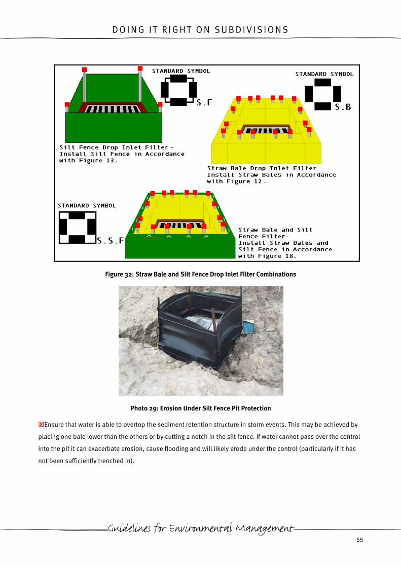
Figure 32: Straw Bale and Silt Fence Drop Inlet Filter Combinations..........................................................55

Figure 33: Mesh and Aggregate Drop Inlet Protection ...............................................................................56
Figure 34: Culvert Entry Gravel Filter.........................................................................................................57
Figure 35: Silt Filter Bung .........................................................................................................................58
Figure 36: Stabilised Site Access Point ................................................................................................... 62
Figure 37: Victorian pH Ranges for Discharge .......................................................................................... 66
Figure 38: Flocculant Dosing Utilising Pump............................................................................................ 69
Figure 39: Portable Settling Tank .............................................................................................................70
Figure 40: Designated Refuelling/ Maintenance Area ...............................................................................97


D O I N G I T R I G H T O N S U B D I V I S I O N S
1 . I N T R O D U C T I O N
The following document highlights a range of temporary environmental protection measures, which may be
employed during the construction of subdivisions. The measures detailed within this document are to mitigate
effects on the environment in relation to the key construction issues of noise, dust, sediment and erosion, waste
and chemicals. This does not imply that these will be the only environmental issues of concern on subdivision
sites. Other site-specific issues may include flora and fauna, archaeological/ heritage items of significance,
contaminated soil, acid sulfate soils, groundwater or odour and should be considered if appropriate to the site.
The appropriateness of different protection measures will vary between sites. Protection measures should be
selected in response to the specific site conditions and the subsequent levels of risk for the issues on that site.
Not all of the measures listed within this document will be appropriate for use on a single site.
Selection of environmental protection measures should focus on those that will prevent the problem as primary
controls rather than relying on those that will treat the problem. For example, rather than spraying water with a
water cart to lay dust, strip only the areas required for works to inhibit dust generation from occurring.
Appropriate installation is imperative when erecting structural environmental protection measures. This ensures
that the structure functions effectively and reduces the amount of maintenance required. On some sites up to 65
per cent of the total costs of environmental management can be attributed to maintenance costs resulting from
insufficient installation of the structures. Designs within this document will aid the installation of environmental
protection structures correctly up-front, minimising the costs of environmental management on site.
Each of the structural environmental protection measures outlined within this document has a standard symbol
associated with it. These standard symbols are for use on site environmental management plans (EMPs), to
depict the measures on the plan. These standard symbols have been developed to create consistency in plans,
thereby aiding individuals in writing and reading them.
The range of protection measures outlined within this document should not be considered finite. Products for
environmental protection during construction are continuously evolving. Experimentation with environmental
protection measures on sites is encouraged and measures that are developed into the future may prove as or
more effective than existing products for a particular site’s conditions.
In addition to fulfilling responsibilities to council, EPA Victoria and Melbourne Water through the implementation
of environmental protection measures, other benefits can also be achieved on site. On site benefits typically
include less risk of works being undermined by erosion or buried by sediment, improved drainage and reduced
site wetness, less dust problems, improved working conditions, reduced down-time after rain, less stockpile
losses, reduced waste disposal costs, reduced site clean-up, earlier works completion, earlier land sales,
avoidance of fines, fewer OH&S issues, and a reduced chance of complaints by neighbours (EPA Victoria
Publication 275).
Guidelines for Environmental Management 1

D O I N G I T R I G H T O N S U B D I V I S I O N S
The temporary environmental protection measures outlined within this document are a single tool in the
environmental management of subdivision construction sites. For successful environmental management, these
should be incorporated into a site EMP, which has a strong organisational commitment for adoption.
To assist in the development of site EMP’s the ‘Site EMP Kit’ may be used. Consisting of a template and guidance
notes, the Site EMP Kit aids in the development of a site EMP consisting of two A1 plans. The Site EMP Kit is
available on the Clearwater Website at: www.clearwater.asn.au. The Clearwater Website is a capacity building
program funded by the Victorian Government through EPA Victoria as part of the Victorian Stormwater Action
Program (VSAP).
EPA Victoria 2

D O I N G I T R I G H T O N S U B D I V I S I O N S
2 . N O I S E
Mismanagement of noise on site has the potential to result in detrimental effects on the health and amenity of
neighbours and employees, OH&S issues and complaints from neighbours. The environmental protection
measures outlined in this section may be used to mitigate these effects.
2.1 Scheduling works to minimise disruption to neighbours
- Restrict working hours in accordance with relevant council and EPA Victoria regulations
EPA Victoria guidelines state that work hours should be restricted to between 7am and 6pm on weekdays and
7am and 1pm on Saturdays (EPA Victoria Publication 480).
Check with the relevant local council to ensure hours of works are in accordance with local regulations.
Noise generated within these restricted working hours should be minimised where possible and must be of a
level that is considered ‘reasonable’.
Schedule noisy activities for the least sensitive times of the day
Disturbance to a sites neighbours will be reduced if noisy works are undertaken at less sensitive times of the day,
such as mid-morning to mid-afternoon.
2.2 Location of noise generating works
Utilise existing or created noise barriers between works and neighbours who may be affected by noise
Vegetation, earth embankments and machinery can all make effective noise barriers on site.
As a general rule most solid objects between the source of the noise and neighbours will make an effective noise
barrier, if the barrier is greater than 0.5m above the highest noise source (CCF and EPA Victoria, 2001).
Locate works, which generate noise as far away from neighbours as possible
Level of noise decreases with distance from the source.
Guidelines for Environmental Management 3

D O I N G I T R I G H T O N S U B D I V I S I O N S
2.3 Utilising quieter work practices
Undertake works using a quieter process where options are available
2.4 Reducing noise from machinery
Select machinery which produces less noise
Old equipment is generally louder than new equipment.
Request information on noise levels from manufacturers or hire companies. Take this information into
consideration when purchasing or hiring equipment (Schneider, 2001).
Ensure machinery is well maintained
Maintenance on machinery can reduce noise levels by up to 50% (Schneider, 2001).
Retrofit older, noisy machinery
Older equipment can be made quieter by simple retrofits including new mufflers or sound absorbing materials
(Schneider, 2001).
2.5 Informing neighbours of potential noise impacts
Inform neighbours of the nature, duration and hours of works if noise from construction activities are likely
to impact on them
Determine the radius of residents from the site that will potentially be affected as a result of activity on the site.
Methods of informing residents may include letter drops or signage.
Inform neighbours prior to any out of hours works that will generate noise
The potential for noise complaints will be reduced if neighbours are made aware of noise generating, out of
hours works in advance. This allows neighbours to make alternative arrangements if necessary.
EPA Victoria 4

D O I N G I T R I G H T O N S U B D I V I S I O N S
2.6 Performance summary of environmental protection measures for noise management
Control Measure Noise Reduction Reduced Neighbour Disturbance Cost
Restricted working hours N H N
Scheduling noisy activities for less sensitive time of the day
N M/H N
Noise barriers- utilising existing structures
N M/H N
Locating noise generating works away from neighbours
N M/H N
Selection of less noisy equipment M M N
Maintaining machinery L/M L/M N- M/H *dependant on initial maintenance regime
Machinery retrofits M M VH
Informing neighbours of noisy/ out of hours works- letter drops
N M M/H
Informing neighbours of noisy/ out of hours works- signage
N L/M M/H
N= Negligible, L= Low, M= Moderate, H= High, VH= Very High, N/A= Not Applicable
Table 1: Performance Summary of Environmental Protection Measures for Noise Management
Guidelines for Environmental Management 5
D O I N G I T R I G H T O N S U B D I V I S I O N S
3 . D U S T
Mismanagement of dust on site has the potential to result in detrimental effects on the health and amenity of
neighbours and employees, reduced visibility on site, increased wear on machinery and equipment, water quality
effects from deposition, complaints from neighbours and OH&S issues. The environmental protection measures
outlined in this section may be used to mitigate these effects.
3.1 Methods to prevent dust generation
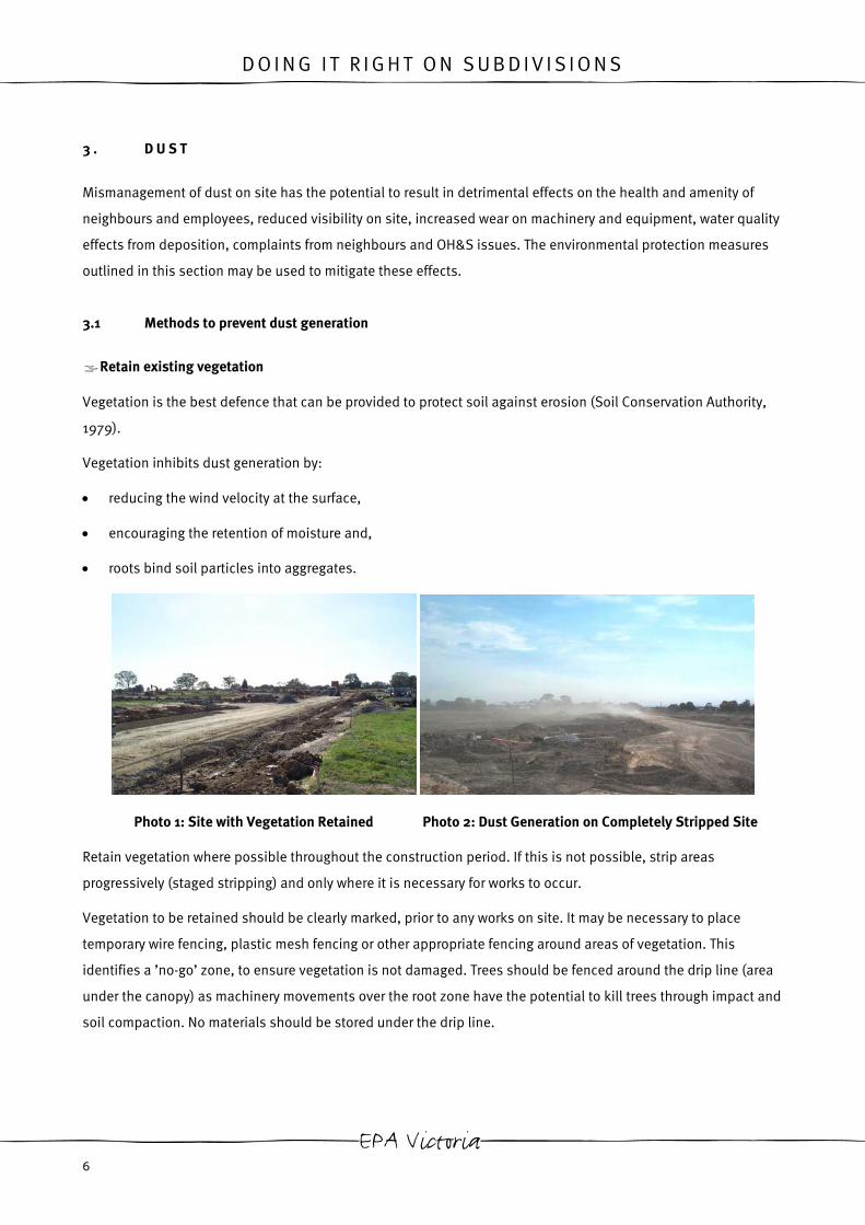
Retain existing vegetation
Vegetation is the best defence that can be provided to protect soil against erosion (Soil Conservation Authority,
1979).
Vegetation inhibits dust generation by:
• reducing the wind velocity at the surface,
• encouraging the retention of moisture and,
• roots bind soil particles into aggregates.
Photo 1: Site with Vegetation Retained Photo 2: Dust Generation on Completely Stripped Site
Retain vegetation where possible throughout the construction period. If this is not possible, strip areas
progressively (staged stripping) and only where it is necessary for works to occur.
Vegetation to be retained should be clearly marked, prior to any works on site. It may be necessary to place
temporary wire fencing, plastic mesh fencing or other appropriate fencing around areas of vegetation. This
identifies a ’no-go’ zone, to ensure vegetation is not damaged. Trees should be fenced around the drip line (area
under the canopy) as machinery movements over the root zone have the potential to kill trees through impact and
soil compaction. No materials should be stored under the drip line.
EPA Victoria 6

D O I N G I T R I G H T O N S U B D I V I S I O N S
Figure 1: Tree Drip Line
Employ stabilisation methods (temporary and permanent)
Stabilisation Matting
Stabilisation matting, also referred to as erosion control matting, may be used to cover exposed areas of unstable
soil which dust may generate from.
When selecting the most appropriate product for your job the following should be taken into consideration:
1. Matting material- stabilisation matting is available in various materials, including biodegradable,
biodegradable/ synthetic and synthetic material. Products with a greater proportion of synthetic material
generally have greater longevity and can withstand higher velocity flows.
2. Thickness- thicker products suppress weed growth. Thick products are commonly used during the
establishment of vegetation such as reeds that are planted in slits in the material. Thin or open weave
products are used where grass is to be established, as grass is able to grow through the material.
3. Infiltration- some synthetic products have the potential to inhibit run-off infiltration into the underlying soil.
This should be taken into account when stabilisation matting is to be used for extensive areas or a long
duration. Where vegetation is to be established with stabilisation matting, synthetic materials can prevent
water from penetrating to the roots.
Matting may be utilised as a temporary or permanent stabilisation measure. Where stabilisation matting will be
used as a permanent measure it should be placed as early as possible in works to provide protection during
construction.
Guidelines for Environmental Management 7

D O I N G I T R I G H T O N S U B D I V I S I O N S
Due to the variation in products it is advisable to consult with suppliers for the most appropriate product for the
job.
Figure 2: Stabilisation Matting (Figures from NSW Dept. of Housing, 1998 and LG Pro, 2002)
Grassing
Establishment of grass may be for permanent or temporary applications. Grassing is particularly useful for
stabilising stockpiles to be retained on site for periods greater than 28 days and exposed areas of the site at the
completion of works.
Methods of grassing include:
• hand sowing- this is labour intensive and therefore only practical for small areas.
• hydroseeding- involves the spraying of a seed, fertiliser, binder/tackifyer and water slurry onto the area to be
grassed. Dye may also be added. This method of application allows large areas to be grassed with greater
strike of seed than hand sowing (TurfMaker, 2000). Straw mulching is frequently used in conjunction with
hydroseeding.
• hydromulching- products including cellulose fibre (eg. mulched newspaper) or wood fibre (eg. wood
byproducts) are sprayed over the soil surface, with or without seed, dye, binder/tackifyer or fertilisers added
(Kerr, G., No Date). Advantages of hydromulching over hydroseeding include its capabilities for erosion
control, holding seed in place during germination, retaining soil moisture, slowing run-off and providing a
EPA Victoria 8

D O I N G I T R I G H T O N S U B D I V I S I O N S
microclimate to promote germination of seed (Aquaseeding, No Date). Hydromulch is suitable for application
to large areas, however is a costlier method than hydroseeding.
Photo 3: Hydromulching (a and b) Application for Subdivision Post Works Stabilisation (c) Application to
Stockpile (courtesy of Aquaseeding)
Where used as a temporary measure, seed used for any of the above methods should be sterile to prevent the
spread of the grass.
Mulch
Mulch is generally utilised as a permanent stabilisation measure, by providing a barrier between the wind and
exposed soil. Mulching is most effective when combined with revegetation. Where permanent mulching is to be
undertaken it should be placed as early as possible during works to prevent erosion during the construction
phase.
Temporary applications of mulch may be appropriate for some sites. Materials for temporary mulching can
include local brush or straw.
It is necessary to ensure run-off flows are directed away from mulched areas, to ensure mulch is not washed
away.
Guidelines for Environmental Management 9

D O I N G I T R I G H T O N S U B D I V I S I O N S
Figure 3: Mulching (Figures from NSW Dept. of Housing, 1998 and LG Pro, 2002)
Progressive Revegetation
At the completion of an area of works, the area should be immediately revegetated to inhibit the generation of
dust.
Revegetation may include:
• planting areas of permanent vegetation
• planting grassed nature strips (instant turf can provide rapid stabilisation)
• temporary grassing of areas where permanent vegetation will not be planted (eg. lots).
EPA Victoria 10
D O I N G I T R I G H T O N S U B D I V I S I O N S
Photo 4: Revegetation of Completed Areas of Site
Roughen surface of exposed soil
Leave areas of exposed soil rough to reduce the velocity of wind at the surface. Where possible, rip smooth areas
of exposed soil. (CCF and EPA Victoria, 2001)
Cover stockpiles and locate them where they are protected from wind
Stockpiles are vulnerable to dust generation, as the material is generally quite loose and exposed to the wind.
Cover stockpiles with tarpaulins, geotextile, stabilisation matting or other suitable materials to provide a barrier
between wind and the exposed soil.
Locate stockpiles in areas where they are protected from wind. Utilise existing landforms or vegetation as wind
breaks.
Restrict vehicle movements
Vehicle movements have the potential to generate dust by dislodging soil particles and creating air movement
behind the vehicle.
Restrict vehicle movements to defined haul roads, as these may be targeted for dust suppression.
Speed restrictions can be utilised to minimise the generation of dust. Vehicles travelling at lower speeds generate
air movement of a lower velocity. As a general rule speeds should be restricted to less than 40km/hr on site.
Prevent generation of dust when transporting material
Wet down or cover loads when there is potential for dust to be generated from the material being transported.
Guidelines for Environmental Management 11

D O I N G I T R I G H T O N S U B D I V I S I O N S
Construct wind breaks such as wind fences
Where dust is a significant issue on site, a wind fence may be a suitable control to inhibit dust generation. A fence
acting as a windbreak will inhibit the generation of dust to a distance 15 times its height (NSW Dept. of Housing,
1998).
In order for the fence to work effectively ensure that it is installed perpendicular to the prevailing wind (US EPA,
2003).
Figure 4: Wind Fence (Figures from NSW Dept. of Housing, 1998)
3.2 Dust suppression measures
Spray water
Water increases soil cohesion (particles stick together), which inhibits the generation of dust.
Water may be applied through the use of water carts, sprinkler systems or by hand held watering. Care must be
taken to ensure that the method of applying water does not result in contaminated water. Excessive application of
water has the potential to create turbid run-off.
Spraying of water should focus on areas where dust is most likely to be generated. In particular haul roads, areas
of earthworks and stockpiles should be targeted.
EPA Victoria 12

D O I N G I T R I G H T O N S U B D I V I S I O N S
Water should not be sprayed at the site access point. This can allow mud to be transported onto the adjoining
road.
Photo 5: Dust Suppression by Watercart
Dust suppressants
Different categories of dust suppressants include:
Salts: These are generally ionic in nature and are hygroscopic chemicals that adsorb water from the surrounding
environment, thus enabling retention of a greater proportion of particles on the surface by keeping the road dust
moist.
Bitumens: such as asphalt: These are predominantly organic materials derived from petroleum. They act as
adhesives to bond soil particles together.
Lignin sulfonates: These are organic non-bituminous materials with ionic characteristics. They function through
a combination of electrostatic and hydrophobic effects and bind soil particles together to increase particle mass
and cohesion.
Surfactants: Chemicals that reduce water surface tension and allow available moisture to more effectively wet the
particles and aggregates in the surface layer.
Polymers: Long-chain molecular compounds that act as adhesives to bond soil particles together.
Resin or petroleum emulsions: Non-water-soluble organic carbon compounds that are emulsified or suspended
in water and also act by binding soil particles together.
Microbiological binders: Many enzymes are adsorbed by clay particles, resulting in compression of the pore
space that aids in compaction and reduces dust generation.
Other: Generally plant-derived extracts from roots, seeds or beans, formulated as emulsions. These extracts are
generally oils and are non-toxic, and biodegradable. They shed water after curing. They are claimed to be
economical and environmentally benign.
(Szydzik and Patti, 2004)
Guidelines for Environmental Management 13

D O I N G I T R I G H T O N S U B D I V I S I O N S
Historically, EPA Victoria has not found the use of organic petroleum products acceptable for the use of dust
suppression, because of their potential to impact on the environment. Enforcement action would be taken if
waste oil was used for this purpose.
When selecting a dust suppression product, it is imperative to ensure that the dust suppressant will have no
adverse effects on the environment. Request a copy of the material safety data sheet (MSDS) from the supplier, to
determine any effects the dust suppressant may have on the environment and any practices that need to be
employed to mitigate these potential effects.
Dust suppressants that use water as a carrying agent are practical for use on subdivision sites, as these can
easily be added to water sprayed by a water cart. Further to easy application, many of these products reduce the
frequency that areas must be watered. Therefore larger areas can be targeted for dust suppression, using fewer
resources and savings in water usage can be achieved.
Due to the variation in available products it is advisable to consult with the supplier to determine the most
effective product for your job.
3.3 Contingencies in event of dust generation
Restricted activities
Activities that result in the generation of dust, such as earthworks and vehicle movements, should not be
undertaken during dry/ windy conditions when dust cannot be sufficiently suppressed.
Stop work
During dry/windy conditions where significant visible dust is being generated it may be necessary to halt works
due to effects on neighbours and OH&S obligations to employees.
EPA Victoria 14

D O I N G I T R I G H T O N S U B D I V I S I O N S
3.4 Performance summary of environmental protection measures for dust management
Control Measure Minimisation of Dust Generation Dust Suppression Cost
Preventing generation
Retain existing vegetation H/VH N/A N
Temporary fence areas for vegetation
retention
VH N/A M
Stabilisation matting H N/A M/H
Grassing- hand sown H N/A M
Grassing- hydroseeding H N/A H
Grassing- hydromulching VH N/A H/VH
Mulch M N/A H
Progressive revegetation VH N/A N
Ripping smooth oil surfaces L/M N/A M
Covering stockpiles H N/A M/H
Define haul roads M N/A H
Speed restrictions M N/A N
Guidelines for Environmental Management 15
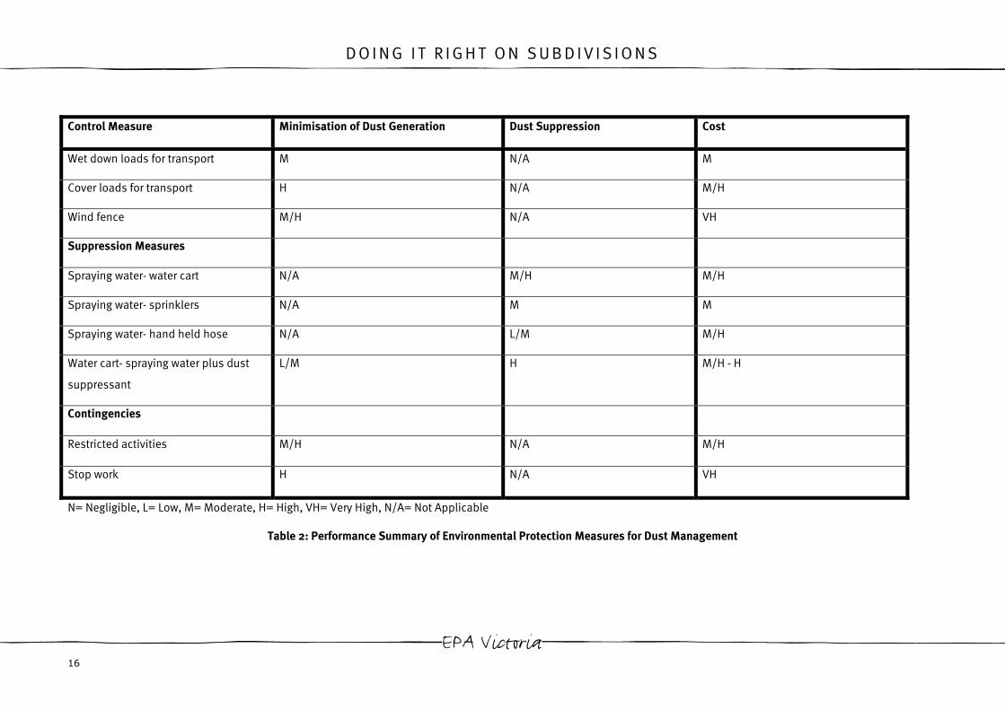
D O I N G I T R I G H T O N S U B D I V I S I O N S
Control Measure Minimisation of Dust Generation Dust Suppression Cost
Wet down loads for transport M N/A M
Cover loads for transport H N/A M/H
Wind fence M/H N/A VH
Suppression Measures
Spraying water- water cart N/A M/H M/H
Spraying water- sprinklers N/A M M
Spraying water- hand held hose N/A L/M M/H
Water cart- spraying water plus dust
suppressant
L/M H M/H - H
Contingencies
Restricted activities M/H N/A M/H
Stop work H N/A VH
N= Negligible, L= Low, M= Moderate, H= High, VH= Very High, N/A= Not Applicable
Table 2: Performance Summary of Environmental Protection Measures for Dust Management
EPA Victoria 16

D O I N G I T R I G H T O N S U B D I V I S I O N S
4 . E R O S I O N A N D S E D I M E N T
Photo 6: Sediment Deposition
Mismanagement of erosion and sediment on site has the potential to result in detrimental economic, safety and
ecological effects. Build up of sediment in drainage pipes and pits results in costs for de-silting and the potential
for flooding. Sediment deposition on roads and footpaths can result in falls from slippery surfaces or vehicle
accidents on slippery roads. Ecological effects include change of habitats (rocky bottom systems become sandy
bottom systems), smothering of food sources, fish respiration is affected as gills become clogged, reduced
feeding ability in visual aquatic predators, smothering of macroinvertebrates, smothering of vegetation,
transportation of pollutants attached to sediment and reduced light penetration for aquatic vegetation. (EPA,
2003). The environmental protection measures outlined in this section may be used to mitigate these effects.
4.1 Measures to inhibit erosion generation
Stage works
• Limit the time that areas are left exposed on site. Strip only when necessary and undertake progressive
rehabilitation.
• Minimise the size of areas left exposed.
• Schedule high-risk works for the drier time of the year.
Install structures to divert flow from entering the site and from exposed soils on site.
Located on the up-slope side of a site, structures to divert water flows can help to prevent clean surface run-off
from entering the site. A diversion structure located up-slope of a site can lessen erosion, site wetness and the
amount of run-off that will require treatment through sediment retention measures.
Guidelines for Environmental Management 17

D O I N G I T R I G H T O N S U B D I V I S I O N S
Run-off on site should be diverted away from areas that are exposed or particularly sensitive to erosion (such as
stockpiles or batters) to reduce erosion on the site.
Alternatively, diversion structures can be located on the down-slope side of a site. In this application they are
used to divert sediment-laden run-off created on site to sediment retention structures, preventing turbid
discharge from the site (US EPA, 2003).
Catch drains
Catch drains, also known as cut and fill diversion channels, are excavated drainage paths. Catch drains should be
stabilised within 14 days of installation through the use of grassing, stabilisation matting or rock armouring (ACT,
1998).
Figure 5: Catch Drain (Figures from ACT, 1998 and NSW Dept. of Housing, 1998)
Cut-off drains
Cut-off drains are temporary applications of catch drains for installation less than five days. These are particularly
useful for capturing and channelling sheet flow from exposed areas. They reduce the length of the run-off flow
path, thereby reducing the velocity and associated erosivity of flow.
Cut-off drains may be cut by a grader or other appropriate machine at the end of a day’s work or immediately prior
to rain. Cut-off drains should be constructed along the contour and should be spaced a maximum of 80m apart
(NSW, 1998).
EPA Victoria 18

D O I N G I T R I G H T O N S U B D I V I S I O N S
Earth banks
Earth banks, otherwise known as all-fill diversion banks, are berms of compacted earth used for channelling
water to a desired location. As with catch drains, earth banks should be stabilised within 14 days of installation
(ACT, 1998).
Figure 6: Earth Bank (Figures from ACT, 1998)
Photo 7: Breach of an Undersized Catch Drain
Guidelines for Environmental Management 19

D O I N G I T R I G H T O N S U B D I V I S I O N S
Catch drains and earth banks that are undersized for the site may breach, resulting in uncontrolled run-off
flows. To prevent this from occurring, these structures should be designed in response to each individual site’s
conditions. Flow rates, cross slopes and the material must be taken into consideration.
Level spreader
A level spreader should be used at the outlet of a catch drain or earth bank to convert the concentrated flow to
sheet flow.
Figure 7: Level Spreader (Figures from ACT, 1998)
Slopes and batters
Down drains or lined channels may be used to transport water down slopes and batters without eroding them.
A catch drain or earth bank is constructed along the top of the batter to prevent uncontrolled flow down the batter
and to direct run-off to the down drain or lined channel.
EPA Victoria 20

D O I N G I T R I G H T O N S U B D I V I S I O N S
Figure 8: Down Drain (Figures from NSW Dept. of Housing, 1998 and ACT, 1998)
A lined channel should be constructed similarly to a down drain, excepting a channel is cut down the batter in
place of a pipe and the channel is lined with stabilisation matting or geotextile.
Photo 8: Lined Channels (courtesy of Tony King, CPESC)
Guidelines for Environmental Management 21

D O I N G I T R I G H T O N S U B D I V I S I O N S
Energy dissipater
An energy dissipater should be used at the outlet of a down pipe or lined drain to slow velocity and associated
erosivity of flow.
Figure 9: Energy Dissipater (Figures from NSW Dept. Housing, 1998 and ACT, 1998)
Employ stabilisation methods (temporary and permanent)
Many of the stabilisation methods utilised to inhibit dust generation may also be applied to inhibit erosion.
These include:
• Stabilisation matting- provides a barrier between run-off flows and exposed soil. Stabilisation matting is
particularly useful in areas where concentrated flows of run-off occur (eg within catch drains, drainage
channels, outfall drains).
• Grassing- inhibits sediment entrainment by reducing the effects of raindrop impact, reducing the velocity
of run-off, increasing soil permeability and roots bind soil particles into aggregates. Grass may also act
as a filter to trap soil particles that are already entrained.
• Mulch- inhibits sediment entrainment by reducing the effects of raindrop impact and reducing the
velocity of run-off.
• Revegetation- as per temporary grassing.
EPA Victoria 22

D O I N G I T R I G H T O N S U B D I V I S I O N S
For further details and installation instructions for these measures see Section 3.1.
Photo 9: Stabilisation Matting Used to Stabilise Drainage Channel (Courtesy of Treemax)
Rock armouring
Photo 10: Rock Armoured Drainage Channel
Rock armour is a layer of rock, which provides a barrier between exposed soils and run-off and slows the velocity
of flow. It is utilised in areas of concentrated flow and is particularly effective for use in drainage channels, catch
drains, outfall drains and outlets/ inlets to sediment basins.
For temporary applications, rock may be placed with or without a geotextile liner. However, use of a liner under
the rock will reduce the likelihood of undermining and can reduce the thickness of rock to be placed.
When determining the size of rock, ensure that the rocks are large enough to resist dislodgment by peak water
flows (EPA Victoria Publication 275). It is recommended that an assortment of rock sizes are used, instead of one
uniform size (US EPA, 2003).
Guidelines for Environmental Management 23

D O I N G I T R I G H T O N S U B D I V I S I O N S
Figure 10: Rock Armouring- Cross Section
(Figures from EPA Victoria Publication275and NSW Dept. of Housing, 1998)
Protect stockpiles from erosion
Protect stockpiles by applying the following measures:
• up slope catch drains
• down slope sediment retention structures eg. silt fence
• temporary grassing for stockpiles in place greater than 28 days
• position away from drainage lines and at least 10m from waterways
• cover stockpiles with tarpaulins, geotextile, stabilisation matting or other suitable material
• minimise the number and size of stockpiles
• maximum 2:1 height to width ratio (Stormwater Committee, 1999)
EPA Victoria 24

D O I N G I T R I G H T O N S U B D I V I S I O N S
Photo 11: Silt Fence at Base of Stockpile
Figure 11: Stockpile Protection (Stormwater Committee, 1999)
Guidelines for Environmental Management 25

D O I N G I T R I G H T O N S U B D I V I S I O N S
Photo 12: Eroded Stockpile
Avoid large stockpiles with steep batters, as they are particularly vulnerable to erosion.
Roughen surface of exposed soil
Leaving areas of exposed soil rough will decrease erosion by reducing the velocity of run-off and increasing
infiltration.
Where soil is roughened by ripping or with tracked machinery, ensure that the groves are along the contour.
Areas of rough soil will also aid the establishment of vegetation (US EPA, 2003).
4.2 Measures for sediment retention
Sediment retention structures are utilised for the trapping of entrained sediment in run-off.
Sediment retention structures capture sediment by:
• filtration as run-off passes through the material of the structure
• pondage of run-off behind the structure and the associated settling of particles by gravity
• reducing the velocity of run-off.
Sediment retention structures generally comprise of one or more of the following materials:
• geotextile (including silt fence)
• straw bales, coir logs and other natural materials
• synthetic filters (for example dacron)
• rock/gravel
• vegetation
EPA Victoria 26

D O I N G I T R I G H T O N S U B D I V I S I O N S
• earth.
This section outlines how these materials, and combinations of these materials, can be used to capture
sediment.
Sediment retention structures should be designed and installed to cater for the predicted flows from a one in two
year storm event (two-year ARI with intensity of six hours) (EPA Victoria Publication 480). Bypasses should be
maintained for all sediment retention structures to provide an alternative flow path in the event of a storm
exceeding the one in two year storm event.
Install sediment retention structures on the downslope perimeter of the site to inhibit sediment from leaving
the site through surface run-off flows
Where perimeter controls are utilised, ensure that the area on the down-slope side of the structure is stabilised.
This will ensure that the treated run-off does not pick up sediment prior to exiting the site.
Straw bales
Straw bales are commonly used for sediment retention due to their low initial cost and accessibility. For effective
treatment utilising straw bales:
• Ensure that straw bales are selected when purchasing bales for sediment retention structures. Hay bales
should not be used due to their seed content.
• A line of straw bales should service a catchment no greater than 0.5Ha (ACT, 1998).
• Regularly replace bales. Due to the decomposition of bales, straw bales generally require replacement
approximately every three months. When selecting bales, the high maintenance requirements should be
taken into consideration. If three-monthly replacement cannot be achieved, an alternative, more robust
measure should be selected.
Guidelines for Environmental Management 27

D O I N G I T R I G H T O N S U B D I V I S I O N S
Figure 12: Straw Bales (VSAP Building Construction Sites Project Group, 2003 and LG Pro, 2002)
Photo 13: Gap Between Straw Bales
When installing straw bales ensure that no gaps are left between the bales. If a gap is left between bales all
run-off will flow through this point and sediment-laden run-off will not be treated. Run-off flowing through a gap
concentrates flow, which can exacerbate erosion. Prevent gaps between bales by angling the first stake in each
bale toward the previously installed bale to push them together. Any loose straw should be placed up-slope of
the straw bales, as it will fill any smaller gaps during run-off flows.
Due to the difficulty in ensuring that there are no gaps between bales, it is advisable that a silt fence is installed
in conjunction with straw bales (see Figure 17).
EPA Victoria 28

D O I N G I T R I G H T O N S U B D I V I S I O N S
Silt fence
Silt fences are temporary, permeable barriers of geotextile, installed within a trench and supported by star pickets
or wooden posts. They are not appropriate for use in areas of concentrated flow and should not service a
catchment area greater than 0.6Ha per line of fence (ACT, 1998).
Silt fences may be reinforced with wire mesh or by placing star pickets every metre where there is a risk of them
being knocked over by run-off, work activities or wind.
Silt fences are effective for removal of coarse sediment however have limited to no filtering capacity for fine and
dispersive soils. Percentage removal of suspended solids from a standard, well-installed and maintained silt
fence has been reported at the levels in Table 3. It should be noted that removal rates are highly dependent on
local conditions and installation, and should only be considered as a guide.
Table 3: Percentage Removal of Suspended Solids by a Silt Fence (US EPA, 2003)
Soil Type Percentage Removal
Total suspended solids 70%
Sand 80-90%
Silt-loam 50-80%
Silt-clay-loam 0-20%
The maximum allowable slope length, contributing run-off to a single line of silt fence, should be in accordance
with Table 4.
Table 4: Maximum Allowable Slope Lengths Contributing Run-off to a Single Line of Silt Fence (ACT, 1998)
Slope V:H Maximum Slope Length (m)
1:2 15
1:3 25
1:4 40
1:5 50
Flatter than 1:5 60
Guidelines for Environmental Management 29

D O I N G I T R I G H T O N S U B D I V I S I O N S
Figure 13: Silt Fence (VSAP Building Construction Sites Project Group, 2003)
Figure 14: Line of Silt Fence
EPA Victoria 30

D O I N G I T R I G H T O N S U B D I V I S I O N S
Silt fences should not be installed so that run-off can pass around them. Silt fences should be constructed
along the contour, with the ends turned up slope to ensure that any build up of run-off behind the fence cannot
pass around it (see Figure 14).
Photo 14: Sediment Fence with Inadequate Backfill
When installing silt fences or straw bales ensure that they are trenched into the ground and appropriately
backfilled and compacted. Silt fences and straw bales treat contaminated run-off through two methods. Some
filtration is achieved when water passes through the silt fence or straw bale. However, the majority of sediment is
retained through the ponding of run-off behind the silt fence or straw bale and the subsequent dropping of
sediment particles out of the water column by gravity. This can be observed in Photo 14 where the majority of
sediment retained is in the area where the water has ponded and not on the fence itself. If run-off can pass under
the silt fence or straw bale, filtration and ponding will not occur, and the run-off will not be treated.
Photo 15: Sediment Retained by Silt Fence and Straw Bale Sediment Fence
Guidelines for Environmental Management 31

D O I N G I T R I G H T O N S U B D I V I S I O N S
Install structures to slow the velocity of run-off and encourage the settling of particles.
Grass filter strips
As run-off passes through the grass of the grass filter strip, the velocity is decreased and sediment drops out of
suspension.
Figure 15: Grass Filter Strip (Figures from NSW Dept. of Housing, 1998 and LG Pro, 2002)
Figure 16: Minimum Width of a Well Grassed Buffer Strip (LG Pro, 2002)
When installing grass filter strips ensure that the grass is not installed higher than the adjacent ground
surface. This ensures that run-off can flow onto the grass filter strip and not along the edge of the strip.
EPA Victoria 32

D O I N G I T R I G H T O N S U B D I V I S I O N S
Straw Bale and Silt Fence
The combination of these two products gives this control integrity in an area of concentrated flow, where only silt
fence can be knocked down and only straw bales can be broken up.
Photo 16: Straw Bale/ Silt Fence Sediment Control During Incorrect Installation
Silt fence should be placed on the up-slope side of the structure. Where silt fence is placed on the downslope
side of the straw bales, it is able to balloon out in flows. Correct installation will also reduce damage to the straw
bales, as the silt fence provides a buffer between the bales and direct run-off impact. This in turn reduces
maintenance and the replacement frequency of the bales.
Figure 17: Straw Bale/ Silt Fence (Figures from ACT, 1998 and VSAP Building Construction Sites Project Group,
2003)
Guidelines for Environmental Management 33

D O I N G I T R I G H T O N S U B D I V I S I O N S
Rock bund
Rock bunds consist of non-woven geotextile (felt type), encasing rock. The rock size varies between applications
however 100mm rock is effective in many circumstances.
A rock bund should service a catchment no greater than 1Ha (ACT, 1998).
Figure 18: Rock Groyne/ Bund (Figures from ACT, 1998)
Synthetic filters
These permeable synthetic silt filters consist of a geotextile cover, encasing a synthetic filling. As run off flows
through the filter, the geotextile cover captures course particulates and finer particulates are captured within the
filling.
Designs of these products include straw bale replacements and short and long flexible logs.
EPA Victoria 34

D O I N G I T R I G H T O N S U B D I V I S I O N S
Photo 17: Synthetic Straw Bale Replacement (courtesy of Statewide River and Stream Management)
Photo 18: Synthetic Log (courtesy of Statewide River and Stream Management)
The reusable nature of synthetic products makes them a cost-effective alternative to the use of straw bales.
Although the up front cost is generally greater than that of a straw bale, they have a longer lifespan and can be
reused many times. In comparison a straw bale must be replaced approximately every three months, which
generates costs for purchase of new bales and labour costs for three-monthly replacement.
Guidelines for Environmental Management 35

D O I N G I T R I G H T O N S U B D I V I S I O N S
Figure 19: Synthetic Straw Bale Replacement
Figure 20: Synthetic Log
EPA Victoria 36

D O I N G I T R I G H T O N S U B D I V I S I O N S
Coir and other natural, biodegradable logs
Natural, biodegradable logs consist of a natural fibre cover, such as hessian, encasing filtering material such as
seed husks, straw or coir fibres. Although the longevity of these products is less than that of the synthetic
alternatives, the biodegradability of these products has two advantages over synthetic materials:
• If they are damaged and the filling is released to the environment it will not cause environmental damage.
• Where controls are not removed at the end of works they will break down.
Photo 19: Biodegradable Log
Coir logs are the most well known of the natural, biodegradable logs.
Coir is the fibre obtained from the husks of coconuts. Coir logs placed in drainage lines collect silt and sediment
and slow water velocity to reduce erosion. Compared to straw bales, coir logs are more robust (making them
appropriate for use in concentrated flows), longer lasting (2-5 years) and weed free. (Treemax, 2001)
Coir logs may be installed utilising one of the methods shown in Figure 21. The area under the coir log should be
stripped prior to placement, to ensure that it can make firm contact with the ground.
Guidelines for Environmental Management 37

D O I N G I T R I G H T O N S U B D I V I S I O N S
Figure 21: Coir Logs
Check dams
Check dams are small, temporary dams that are generally installed across a channel. They are particularly useful
for placement in unstabilised channels where it is not practical to line the channel. They are also useful for
placement in channels that have been seeded, to provide protection until the seed strikes (US EPA, 2003).
Check dams utilise materials such as straw bales and silt fence, synthetic logs, biodegradable logs, rock bunds or
sandbags to decrease the velocity of flows and encourage settling of sediment.
EPA Victoria 38

D O I N G I T R I G H T O N S U B D I V I S I O N S
Figure 22: Check Dam (Figures from NSW Dept. of Housing, 1998)
When installing sediment retention structures in channels ensure that the bottoms of the outer edges of the
structure are higher than the top of the centre of the structure (ie. Points B are higher than Point A). This allows
run-off to overtop the control in high flow events, rather than pass around it (see Figure 23). The use of a stringline
is a good way to ensure that the levels are correct.
Guidelines for Environmental Management 39

D O I N G I T R I G H T O N S U B D I V I S I O N S
Figure 23: Flow Around Sediment Retention Structure
Divert contaminated flows to sediment traps to allow soil particles to settle or be treated prior to release to
receiving waters
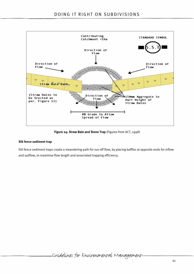
Straw bale and stone sediment trap
Straw bale and stone sediment traps utilise a straw bale bank to divert run-off to a more permeable through–
point of rock. Run-off flows are filtered and dispersed by the rock.
EPA Victoria 40
D O I N G I T R I G H T O N S U B D I V I S I O N S
Figure 24: Straw Bale and Stone Trap (Figures from ACT, 1998)
Silt fence sediment trap
Silt fence sediment traps create a meandering path for run-off flow, by placing baffles at opposite ends for inflow
and outflow, to maximise flow length and associated trapping efficiency.
Guidelines for Environmental Management 41

D O I N G I T R I G H T O N S U B D I V I S I O N S
Figure 25: Silt Fence Sediment Trap (Figures from LG Pro, 2002)
Excavated sediment trap
Excavated sediment traps are shallow excavations where water is able to pond, allowing sediment to drop out of
the water column by gravity.
Excavated sediment traps are particularly useful on the up slope side of other sediment retention structures to
extend the time run-off can pond behind the structure.
When designing excavated sediment traps the surface area should be maximised to encourage the settling of
sediment and infiltration. The depth of the excavation should be approximately 200mm.
Sediment basins
Ideally a qualified professional should design sediment basins, however the following guidance may be used to
design temporary sediment basins to be utilised during the construction phase on site. It should be noted that
the following methodology assumes ideal settling conditions, which rarely occurs in practice (Stormwater
Committee, 1999). Therefore the sizing determined should be considered the minimum for constructing a basin
on site.
EPA Victoria 42

D O I N G I T R I G H T O N S U B D I V I S I O N S
Length
0.5
sV
rQL
=
L = basin length (m)
r = length: width ratio of basin (use minimum of 2:1)
Q = flow rate (m3/s)
Vs = Settling velocity of target sediment (m/s) (From Table 5)
Table 5: Settling Velocities Under Ideal Conditions (Stormwater Committee, 1999)
Classification of Particle Size
Range
Particle Diameter (micrometres) Settling Velocity (metres per
second)
Very coarse sand
Coarse sand
Medium sand
Fine sand
Very fine sand
2000
1000
500
250
125
0.2
0.1
0.053
0.026
0.011
Width
Utilise ratio used for length.
=
r
LW
W = width of basin
L = length of basin
r = length: width ratio of basin
Guidelines for Environmental Management 43
D O I N G I T R I G H T O N S U B D I V I S I O N S
Depth
The depth of a sediment Basin should be between 900mm (NSW Dept of Housing, 1998) and 2m (Melbourne
Water, 2002).
When determining depth of a sediment basin the following should be taken into consideration:
• safety- shallower basins should be constructed if the basin is located in an area accessible to the public. It
may also be necessary to fence the basin, provide gently sloping batters and/or construct benches within the
basin.
• Maintenance- sediment basins should be de-silted when the capacity of the basin has been diminished by a
third as a result of sediment deposition. Shallower basins will require a greater frequency of de-silting.
Figure 26: Sediment Basin (Figures from EPA Victoria Publication275and ACT, 1998)
Where site constraints do not allow for an appropriately sized basin, baffles may be installed to create an
extended, meandering flow path through the basin. Baffles can also prove useful in basins where the inlet and
outlet of the basin is in close proximity.
The sediment basin layout detailed in Figure 26 is one of many types of temporary sediment basins. Variations
include:
• rock sediment basins- rock encased by geotextile is utilised as the basin wall;
• gabion sediment basins- gabions (rock encased in wire) are used to construct the basin wall;
EPA Victoria 44

D O I N G I T R I G H T O N S U B D I V I S I O N S
• earth basin (dry)- as detailed in figure 26. The basin wall consists of compacted earth. Flows out of the pond
are through a riser pipe that allows the basin to be emptied. This basin is preferred as it allows outflow from
the pond to be controlled. Water may be emptied from the pond when it meets with legislative water quality
parameters. Discharge from the pond can be halted by capping the end of the pipe when it does not.
• Earth basin (wet)- as with dry earth basins the basin wall consists of compacted earth. Flow out of the pond
occurs during rainfall events, when the basin overflows via a spillway.
In stream sediment retention measures
In stream sediment retention measures should be considered a last resort or used where works abut a water
body. They should not be relied upon as the sole measure of erosion and sediment management.
Floating silt curtains
Floating silt curtains consist of a curtain of geotextile that is supported in a water body by floats and weights.
They are only suitable for areas of low velocity flows.
When installing floating silt curtains in a channel, ensure that the float width equals the channel width. The
geotextile curtain sides should be graduated downwards to match the channel sides. This will inhibit erosion at
the sides of the channel.
Photo 20: Floating Silt Curtain (Courtesy of Geofabrics Australasia)
Guidelines for Environmental Management 45

D O I N G I T R I G H T O N S U B D I V I S I O N S
Figure 27: Floating Silt Curtain (Figures from NSW Dept. of Housing, 2003)
Rock bunds
Rock bunds utilised for in-stream sediment retention should be constructed so that water flows are able to
overtop the bund during high flow events. The structure should be permeable enough to allow water to pass
through the control during low flow events. Rock bunds should not act as a dam.
Photo 21: Rock Bund Across Creek (a) During High Flow Water is Able to Overtop
(b) During Low Flows Captured Sediment is Visible
See page 35 for further information and design details.
EPA Victoria 46

D O I N G I T R I G H T O N S U B D I V I S I O N S
Synthetic silt filters
Synthetic silt filters can be formed into various filtration devices including composite silt curtains and standpipe
filters. Composite silt curtains may be constructed of materials such as plastic mesh encasing combed synthetic
fibres. A line of composite silt curtain may be installed across a water body. In this application it can act as a litter
boom in addition to capturing sediment.
Photo 22: Trapped Sediment Visible on a Composite Silt Curtain (Silt Cell) During Low Flow Conditions
Figure 28: Composite Silt Curtain
Guidelines for Environmental Management 47

D O I N G I T R I G H T O N S U B D I V I S I O N S
Synthetic silt filters may be used around standpipes, in a similar application to the use of a stocking or filter sock.
Where installed around a standpipe the gap in the top of the structure is equal to the size of the pipe, to allow
overtopping in storm events.
Photo 23: Synthetic Silt Filter Around a Standpipe
Protect constructed drainage structures
Structures to protect drainage systems should filter sediment, while maintaining flow into the drainage system.
Maintaining flow is essential, as it prevents flooding and prevents run-off from bypassing protected inlets and
entering the drainage system further down-slope.
Care must be taken if using sediment retention structures to protect existing roadside drainage. Ensure it does
not pose a hazard to traffic, as an obstacle or by creating pondage of water on the road. It is imperative that a
bypass into the drainage inlet is maintained in this circumstance, to ensure run-off can enter the inlet in a storm
event.
Sandbag sediment barrier
Sandbag sediment barriers are unsuitable controls for trafficked roads as they are an obstruction to vehicles.
EPA Victoria 48

D O I N G I T R I G H T O N S U B D I V I S I O N S
Figure 29: Sandbag Sediment Barrier (Figures from LG Pro, 2002)
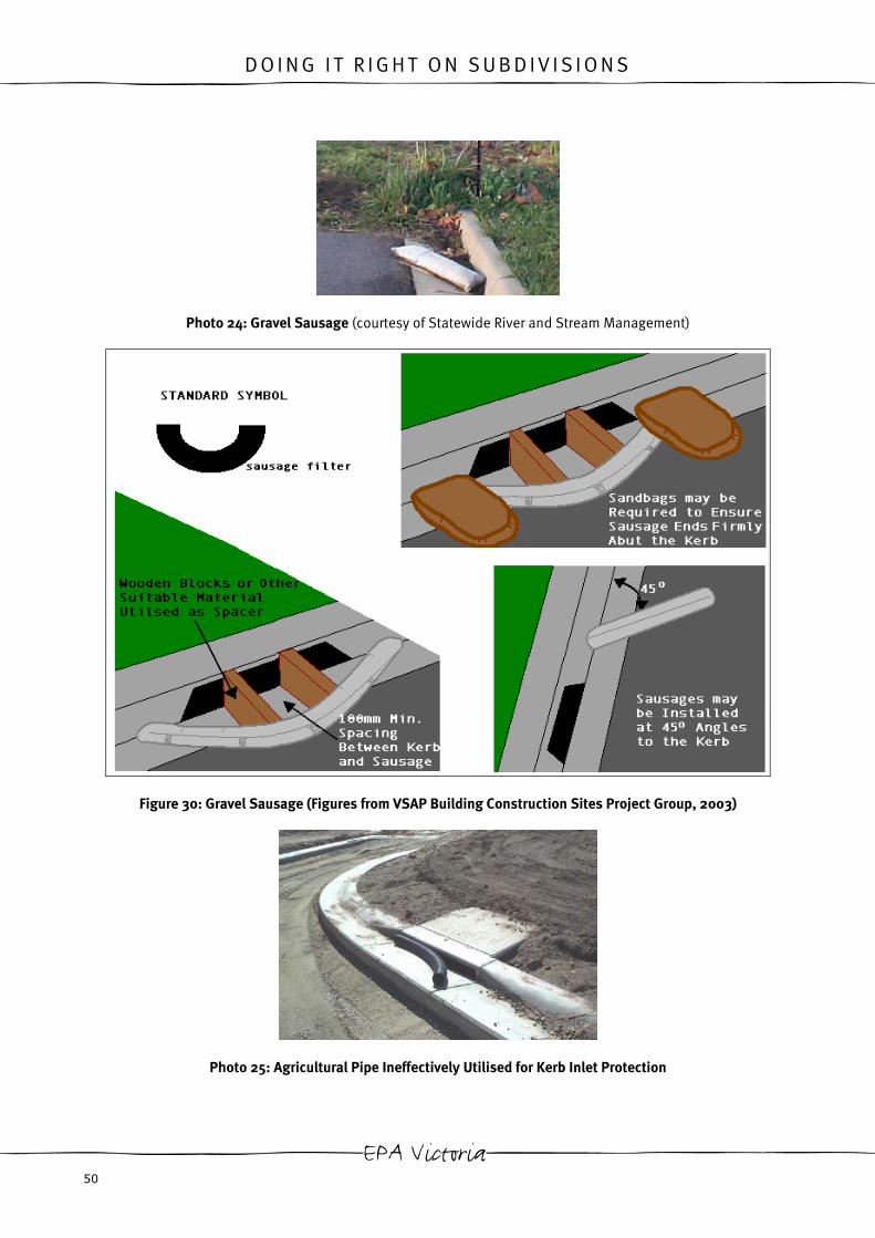
Gravel sausages
Gravel sausages are permeable sacks (may be geotextile, synthetic netting or wire) that are pre-filled or filled by
the user with materials such as coarse sand or aggregate up to 50mm. The permeability and filtration
effectiveness of gravel sausages is determined by the nature of the encasing material and the fill material.
Gravel sausages are often utilised for kerb inlet protection due to their low cost, ease of installation and their
ability for reuse.
When installing gravel sausages for kerb inlet protection ensure that a 100mm minimum spacing is maintained
between the kerb inlet and the gravel sausage. This ensures that in storm events the inlet is not completely
blocked, allowing excess run-off to overtop the gravel sausage and enter the drainage system.
When installing gravel sausages at 45 degree angles to the kerb, ensure that they face upstream and that the
kerbside end of the sausage is depressed to create a spillway.
Variations to gravel sausages for kerb inlet protection are recent developments by erosion control suppliers and
may prove appropriate for use on sites. Examples include sausages made of biodegradable materials (for
example a hessian casing, which is filled with grain husks) and synthetic sausages (for example a geotextile
casing, which is filled with combed synthetic fibres).
Guidelines for Environmental Management 49
D O I N G I T R I G H T O N S U B D I V I S I O N S
Photo 24: Gravel Sausage (courtesy of Statewide River and Stream Management)
Figure 30: Gravel Sausage (Figures from VSAP Building Construction Sites Project Group, 2003)
Photo 25: Agricultural Pipe Ineffectively Utilised for Kerb Inlet Protection
EPA Victoria 50

D O I N G I T R I G H T O N S U B D I V I S I O N S
Although frequently used, agricultural pipe rarely provides adequate kerb inlet protection. Firm contact with the
edges of the inlet is infrequently achieved, allowing run-off to pass around, rather than through the pipe.
Agricultural pipe also has a tendency to float allowing run-off to pass underneath the pipe. Where agricultural
pipe is wedged into the inlet a bypass into the pit for high flows cannot be achieved. This can result in flooding or
water to bypass the control and enter another inlet further downslope. Where agricultural pipe is wedged into an
inlet, it will often ‘pop’ out or enter the drainage system.
Coir logs
Coir logs may be utilised to protect drainage inlets on site. These can be particularly useful for inlets which
require protection for greater than three months, as a substitute for straw bales.
Photo 26: Coir Log Utilised for Inlet Protection
See Section 4.3 for further information and design details
Block and gravel inlet filter
Block and gravel inlet filters should not be used where there is potential for them to be damaged. Where damage
to the structure occurs, any gaps between the concrete blocks can allow gravel to enter the stormwater system in
addition to untreated run-off.
Guidelines for Environmental Management 51

D O I N G I T R I G H T O N S U B D I V I S I O N S
Figure 31: Block and Gravel Inlet Filter (Figures from LG Pro, 2002 and Stormwater Committee, 1999)
Silt fence under grate
Silt fence material may be placed under the grate of inlets to prevent sediment from entering the stormwater
system. The fit must be tight and a minimum of 100mm of silt fence material should be left overhanging at the
edges, to compensate for the weight of trapped sediment.
This method of sediment retention requires regular cleaning, as it can become quite heavy resulting in OH&S
issues.
Silt fence placed under the grate is not recommended for inlets with anticipated high flows. This structure has no
bypass into the drainage system and can result in flooding in the event of high flow conditions.
EPA Victoria 52

D O I N G I T R I G H T O N S U B D I V I S I O N S
Temporary
Some temp
around the
cannot pas
Temporary
OH&S oblig
Photo 27: Silt Fence Placed Under Grate with Captured Sediment
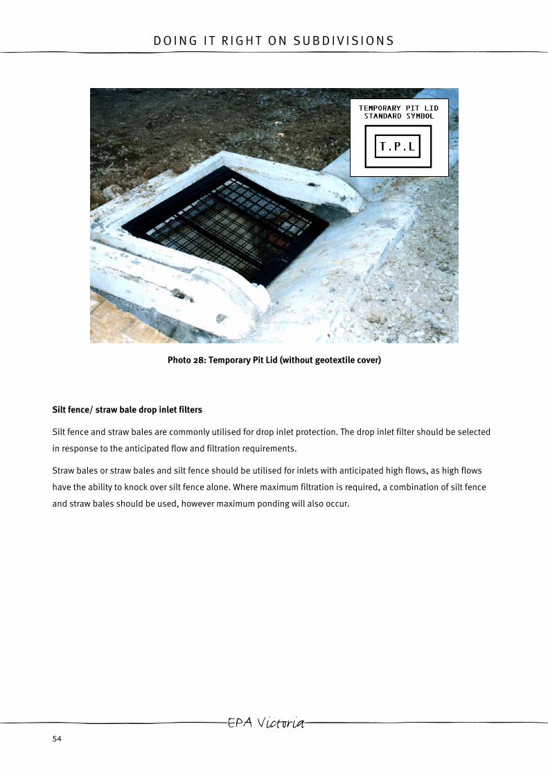
pit lids
orary pit lids are manufactured to allow silt fence or other suitable geotextile to be effectively wrapped
lid. These temporary pit lids ensure a firm fit for the pit. This ensures that sediment-laden water
s under the pit lid, as is often encountered with wooden pit covers wrapped in silt fence.
pit lids that allow for sediment control are an effective way of fulfilling a site’s environmental and
ations for pit protection.
Guidelines for Environmental Management 53
D O I N G I T R I G H T O N S U B D I V I S I O N S
Photo 28: Temporary Pit Lid (without geotextile
Silt fence/ straw bale drop inlet filters
Silt fence and straw bales are commonly utilised for drop inlet protection. The
in response to the anticipated flow and filtration requirements.
Straw bales or straw bales and silt fence should be utilised for inlets with ant
have the ability to knock over silt fence alone. Where maximum filtration is re
and straw bales should be used, however maximum ponding will also occur.
EPA Victoria 54
cover)
drop inlet filter should be selected
icipated high flows, as high flows
quired, a combination of silt fence
D O I N G I T R I G H T O N S U B D I V I S I O N S
Figure 32: Straw Bale and Silt Fence Drop Inlet Filter Combinations
Photo 29: Erosion Under Silt Fence Pit Protection
Ensure that water is able to overtop the sediment retention structure in storm events. This may be achieved by
placing one bale lower than the others or by cutting a notch in the silt fence. If water cannot pass over the control
into the pit it can exacerbate erosion, cause flooding and will likely erode under the control (particularly if it has
not been sufficiently trenched in).
Guidelines for Environmental Management 55

D O I N G I T R I G H T O N S U B D I V I S I O N S
Mesh and aggregate drop inlet protection
As a variation to common silt fence or straw bale drop inlet protection, aggregate supported by mesh may be
used.
Figure 33: Mesh and Aggregate Drop Inlet Protection (Figures from LG Pro, 2002)
Culvert entry gravel filter
Timber planks and gravel may be utilised to construct a temporary filtration device for a culvert entry point.
EPA Victoria 56

D O I N G I T R I G H T O N S U B D I V I S I O N S
Figure 34: Culvert Entry Gravel Filter (Figures from ACT, 1998)
Silt filtering bungs
Permeable silt filtering bungs sit inside pits and are wedged into the pipe. They are available in various sizes to
ensure a tight fit in the pipe. This ensures that water cannot pass around the bung and ensures that the force of
water cannot dislodge it. As an additional measure a bamboo rod is used to hold the bung in place, ensuring it is
not flushed up the pipe.
As the bung is installed inside the pit, it should not be considered ‘out of sight, out of mind’. Bungs should be
regularly checked to ensure they are still correctly positioned and sediment deposited in the bottom of the pit
should be removed.
Photo 30: Silt Filtering Bung (courtesy of Statewide River and Stream Management)
Guidelines for Environmental Management 57

D O I N G I T R I G H T O N S U B D I V I S I O N S
Figure 35: Silt Filter Bung
Straw bales and sandbags utilised for in pit filtration are not effective sediment controls. The low permeability
of these methods also leaves the drainage system vulnerable to flooding.
Photo 31: A Sediment Control?
Install permanent sediment retention structures at commencement of works
Permanent sediment retention structures may be utilised to capture sediment during construction, if they are
amongst the first items to be constructed on site. In particular sediment basins or wetland areas can be valuable
as a back up to on-site erosion and sediment measures.
EPA Victoria 58

D O I N G I T R I G H T O N S U B D I V I S I O N S
Not all permanent sediment retention structures are suitable for intercepting sediment during construction. In
particular, the exacerbated sediment loads on water sensitive urban design structures, such as bioremediation
systems, can have detrimental effects (such as clogging) on these systems, lowering their lifespan. These
structures should not be utilised for sediment retention during construction. It may be necessary to install
temporary sediment retention measures around these permanent sediment retention structures to protect them
during construction.
Permanent sediment retention structures utilised during the construction process will require de-silting at the end
of the construction.
International innovative products
Many countries, in particular USA, have progressed further than Australia in the control of erosion and sediment.
In response to this, many innovative products are available in these countries that are yet to reach Australia. In
the future some of the following types of products may be available here:
• permeable pit covers-consist of a lightweight, rigid plastic frame which supports a geotextile fabric filter.
These are installed over pit openings. See Photo 32.
• Portable silt berms-lightweight, reusable, metal or plastic, transportable berms that may or may not require
wrapping with geotextile. These are used primarily as check dams however may also be used for run-off
diversion, drop inlet protection or site perimeter sediment retention.
• Silt fence machines-these machines slice a narrow trench and automatically feed silt fence into the trench.
This is a useful tool for organisations that undertake significant amounts of silt fence installation, as greater
spans of silt fence can be effectively installed in less time.
• Flocculant blocks-flocculants that are supplied in the shape of a block, to allow for easy and accurate dosing.
Photo 32: Permeable Pit Cover (courtesy of Silt Saver Inc., USA)
Guidelines for Environmental Management 59

D O I N G I T R I G H T O N S U B D I V I S I O N S
De-silting sediment retention structures
De-silting should be viewed as a positive practice as it indicates that the sediment retention device is effective.
The quantity of material that is removed from sediment retention structures would otherwise be deposited in our
waterways.
Sediment retention structures should have built up sediment removed when:
• captured sediment has diminished the capacity of the structure by a third or;
• when built up sediment is inhibiting the structure from working effectively.
Structures such as gravel sausages and rock bunds may also require de-silting internally as sediment is also
captured within these controls. If washing out rock, ensure run-off is directed to a suitable sediment retention
device.
Synthetic silt filters may be de-silted by drying out the filter then beating it. When the filter is clogged and beating
it does not remove the sediment, some suppliers will remove the filling and restuff the outer casing.
Sediment retention structures will not effectively treat run-off if they are not de-silted. Clogging can result in
flooding or run-off bypassing the control and entering the stormwater system further down-slope. Where
structures are not de-silted the captured sediment may be resuspended by water flows in the next rainfall event.
When de-silting sediment retention structures do not stockpile the sediment next to, up-slope or down-slope of
the structure it was removed from. Placing the sediment next to or up-slope of the structure will result in the
sediment being washed back into it. Placing the sediment down-slope of the structure may allow it to wash off
site. Material should be stored at a stable area of the site that is protected from run-off flows.
4.3 Keeping mud off roads
Site access
Minimise the number of access points
Minimising the number of site access points reduces the number of areas required for stabilisation, vehicle
cleaning and areas of road to be targeted for cleaning in the event that mud is tracked onto the road.
Minimise access on and off the site
Restricting vehicle movements on and off site is the most effective way of preventing mud being tracked onto the
road. Vehicle movement restrictions may include:
• restricting vehicle access on and off site during wet weather conditions (ie. when the site is muddy);
EPA Victoria 60
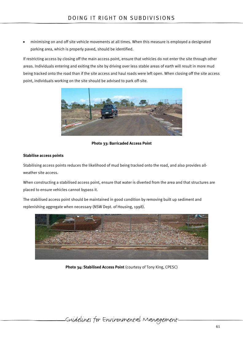
D O I N G I T R I G H T O N S U B D I V I S I O N S
• minimising on and off site vehicle movements at all times. When this measure is employed a designated
parking area, which is properly paved, should be identified.
If restricting access by closing off the main access point, ensure that vehicles do not enter the site through other
areas. Individuals entering and exiting the site by driving over less stable areas of earth will result in more mud
being tracked onto the road than if the site access and haul roads were left open. When closing off the site access
point, individuals working on the site should be advised to park off-site.
Photo 33: Barricaded Access Point
Stabilise access points
Stabilising access points reduces the likelihood of mud being tracked onto the road, and also provides all-
weather site access.
When constructing a stabilised access point, ensure that water is diverted from the area and that structures are
placed to ensure vehicles cannot bypass it.
The stabilised access point should be maintained in good condition by removing built up sediment and
replenishing aggregate when necessary (NSW Dept. of Housing, 1998).
Photo 34: Stabilised Access Point (courtesy of Tony King, CPESC)
Guidelines for Environmental Management 61

D O I N G I T R I G H T O N S U B D I V I S I O N S
Figure 36: Stabilised Site Access Point (Figures from NSW Dept. of Housing, 1998)
Do not exclude the geotextile when constructing a stabilised access point. Exclusion of geotextile will result in
rutting and rock sinking into the underlying mud as vehicles drive over it. This inhibits the stabilised access from
working effectively and generates additional costs of replenishing rock.
Clean vehicles before leaving the site
Cleaning vehicles of dirt or mud may be undertaken by:
• driving the length of a stabilised access track;
• the use of rumble/ vibration grid or ;
• a physical scrape of material from the vehicle.
Where possible avoid using a wheel wash as this generates turbid run-off. Where a wheel wash is used, ensure
that all run-off is directed towards a suitable sediment retention structure.
Driving length of a stabilised access track
As a vehicle drives over the gravel pad, mud and sediment are removed from the vehicle's wheels by the friction
between the tyres and the gravel (US EPA, 2003).
EPA Victoria 62

D O I N G I T R I G H T O N S U B D I V I S I O N S
Rumble grids
Rumble grids are designed to open the tread on tyres and vibrate mud and dirt off the vehicle (in particular the
chassis). Rumble grids may be prefabricated or use materials such as cattle grids, railroad rails or steel bars with
bar spacings 5-20cm apart (Govt. of British Colombia, no date). The material utilised for the grid must be
designed to hold the weight of fully loaded vehicles.
Some rumble grids are designed to be placed over a pit, whereas others have spacer bars under the grid to create
a void between the grid and the ground. Mud and dirt from vehicles passes through the gaps between bars, into
the void or pit under the grid. The rumble grid must be periodically lifted and material collected underneath
cleared out.
Placing rumble grids under water will increase their performance efficiency. This can be achieved by excavating a
shallow pit, placing the rumble grids in the pit, then filling the pit with water.
Rumble grids should be followed by stabilised material, to ensure that vehicles do not pick up mud leaving the
site.
Physical scrape of m
Using a shovel or o
must be taken to pl
Photo 35: Rumble Grid (courtesy of Tony King, CPESC)
aterial
ther suitable device, physically scrape mud/dirt off vehicles before they leave the site. Care
ace material away from the exit track, in an area where it cannot be washed away.
Guidelines for Environmental Management 63

D O I N G I T R I G H T O N S U B D I V I S I O N S
This process is time consuming and all individuals coming onto site must be aware of the requirement for this to
be effective. Therefore, this option is only viable for smaller sites, with few employees and limited vehicle
movements on and off site.
In the event that soil/mud is deposited on the road, remove the material
EPA Victoria does not consider the use of street sweepers or other physical sweeps of material deposited on road
to be an acceptable primary means of sediment control.
These measures should only be used to compliment other measures that prevent material from getting onto the
road, in the event that they have failed.
In circumstances where these above methods will not suffice and the road must be washed, ensure that drainage
inlets are protected with sediment retention structures. Washing down roads, where sediment laden wash water
enters the stormwater system, is unacceptable and may lead to enforcement action for pollution.
Photo 36: Sediment Left on Kerb and Gutter After Street Sweeping
Where street sweepers are used to clean the road, ensure that the kerb and gutter, and kerb inlets are also
cleaned. Street sweepers often miss these areas.
4.4 Dewatering
On-site drainage management will not always prevent the collection of water on-site, and any collected water
needs to be managed to prevent off-site impacts on receiving waters.
Determine if water can be reused on site
Re-use of water on site should always take priority over discharge because:
• discharge to waterways can be harmful;
• water, particularly drinking water, is a scarce and valuable resource;
• using reclaimed water as opposed to buying water will save money.
Examples of re-use are dust suppression and irrigation of vegetation.
EPA Victoria 64

D O I N G I T R I G H T O N S U B D I V I S I O N S
Check the quality of the water to be discharged
Any water discharged to a stormwater drain will eventually flow into surface waters (for example. rivers, creeks,
lakes). Whether water is discharged directly to surface waters, or reaches surface waters indirectly via stormwater
drains, the quality of water discharged needs to be carefully managed to minimise impacts.
Different activities on your construction site will pose different risks to surface waters. This means that the
treatment needed before discharging water will vary, and that you have to look at different water quality
parameters to demonstrate that impacts have been minimised.
For example:
• measuring turbidity will indicate the amount of sediment being discharged into surface waters.
• pH provides a measure of the impact of concreting works, exposure to acid-sulfate soils or pH changes
resulting from the use of flocculants;
• total dissolved solids may suggest the presence of groundwater in the discharge.
To be able to minimise the impacts of discharges, it is important to understand the condition of the water
environment that you are discharging into. The current condition of surface waters varies across Victoria, so some
discharges will need to be of a higher quality than others. To find out about the current condition of surface
waters you can look to water quality monitoring data. This may be already available (for example from Melbourne
Water or EPA), or in some cases may have to be measured. You may need to obtain expert assistance to obtain
information on, and/or measure the condition of surface waters, and the potential impact of your discharges on
receiving waters.
Understanding the surface waters will provide information on the type of treatment needed to make sure that
water is of acceptable quality for discharge. EPA will always require the adoption of best practice management
techniques to ensure that surface waters are protected (for example water to be discharged should be free of
foams, scums, odours, sheens or oil on the surface, unusual colour or concrete slurry prior to discharge). EPA
Victoria’s Environmental Guidelines For Major Construction Sites (EPA Publication 480) states that water
exceeding 30NTU must be treated, so that the turbidity is 30NTU or less during discharge. The exception is where
the receiving waters has a turbidity of less than 30NTU (for example surface waters in less developed areas). In
this circumstance a higher level of treatment is required to ensure the protection of surface waters as specified in
State Environment Protection Policy (Waters of Victoria).
State Environment Protection Policy (Waters of Victoria) provides Victoria’s framework for the protection of surface
waters. It sets environmental quality objectives for parameters such as turbidity, pH and nutrients. These
environmental quality objectives vary across Victoria because the condition of surface waters varies across
Victoria. If these environmental quality objectives are not met, this indicates an environmental risk to surface
waters.
Guidelines for Environmental Management 65

D O I N G I T R I G H T O N S U B D I V I S I O N S
For example, for all surface waters east of the Campaspe/ Goulburn, Maribyrnong/ Yarra, and Maribyrnong/
Goulburn catchment boundaries, and the Grampians and the Otways, the pH should remain between 6.4 and 7.7.
If monitoring of surface waters in these areas indicates that the pH is outside of this range, then the uses and
values of these surface waters may be at risk.
For all areas west of the Campaspe/ Goulburn, Maribyrnong/ Yarra, and Maribyrnong/ Goulburn catchment
boundaries, excluding the Grampians and the Otways (see Figure 37) pH needs to be between 6.5 and 8.3 to
protect the uses and values of these water environments.
Figure 37: Victorian pH Ranges for Discharge (Victoria Government Gazette, 2003)
In order to demonstrate that you are managing discharges from your site adequately and that any water
discharged is of a suitable quality, you will usually need to undertake water quality monitoring.
Constructing a suitable water quality monitoring program for this purpose:
• may require specialist advice;
• will often vary depending on the type, stage and risk associated with a particular part of construction
works, and;
• may need to be approved prior to construction commencing (check contractual or permit requirements)
This water quality monitoring program should be included as part of a site environmental management plan or
equivalent.
Adopting this approach outlined in this section should allow you to satisfy contractual and regulatory
requirements, and will complement the many management activities underway to maintain and improve the
health of surface waters across Victoria.
EPA Victoria 66
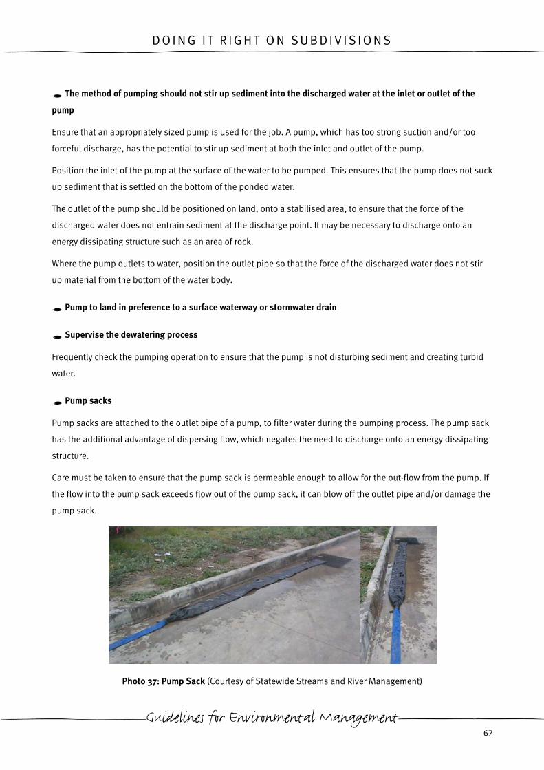
D O I N G I T R I G H T O N S U B D I V I S I O N S
The method of pumping should not stir up sediment into the discharged water at the inlet or outlet of the
pump
Ensure that an appropriately sized pump is used for the job. A pump, which has too strong suction and/or too
forceful discharge, has the potential to stir up sediment at both the inlet and outlet of the pump.
Position the inlet of the pump at the surface of the water to be pumped. This ensures that the pump does not suck
up sediment that is settled on the bottom of the ponded water.
The outlet of the pump should be positioned on land, onto a stabilised area, to ensure that the force of the
discharged water does not entrain sediment at the discharge point. It may be necessary to discharge onto an
energy dissipating structure such as an area of rock.
Where the pump outlets to water, position the outlet pipe so that the force of the discharged water does not stir
up material from the bottom of the water body.
Pump to land in preference to a surface waterway or stormwater drain
Supervise the dewatering process
Frequently check the pumping operation to ensure that the pump is not disturbing sediment and creating turbid
water.
Pump sacks
Pump sacks are attached to the outlet pipe of a pump, to filter water during the pumping process. The pump sack
has the additional advantage of dispersing flow, which negates the need to discharge onto an energy dissipating
structure.
Care must be taken to ensure that the pump sack is permeable enough to allow for the out-flow from the pump. If
the flow into the pump sack exceeds flow out of the pump sack, it can blow off the outlet pipe and/or damage the
pump sack.
Photo 37: Pump Sack (Courtesy of Statewide Streams and River Management)
Guidelines for Environmental Management 67

D O I N G I T R I G H T O N S U B D I V I S I O N S
Use of flocculants
In the event that run-off is too turbid to discharge and sediment is slow to settle naturally out of the water column,
it may be appropriate to use flocculants to accelerate the settlement of suspended solids. Flocculants are
particularly useful after rainfall on sites with small sediment basins or ponding areas, where water requires quick
removal to retain capacity for further rainfall events. Flocculants will be necessary for use on sites with dispersive
soils.
Although other settling agents exist, including ferric chloride, ferric sulfate, polyelectrolytes and common salt,
only gypsum and alum will be discussed here (NSW Dept of Housing, 2003). Other flocculants are not discussed
due to their high environmental impacts and/or difficulty of use. It is strongly advised that gypsum be used in
preference to alum, as it is easier to use and has less chance of having detrimental environmental impacts.
•
•
Gypsum is an effective flocculant comprising of calcium sulfate. Gypsum has limited effect on pH, however its
use can result in a slight rise in salinity levels.
Alum, consisting of aluminium sulfate, produces a faster rate of flocculation than gypsum. However, potential
environmental impacts are greater with the use of alum in comparison to gypsum. Vigilance must be
undertaken to ensure overdosing does not occur, as this will result in the pH being lowered. Likely toxic
impacts on ecology occur at pH levels less than 5.5 due to a release of dissolved aluminium (NSW Dept of
Housing, 1998). Alum should not be used in waters with a pH less than 5.5 or where dosing has the potential
to lower the pH to less than 5.5. Accurate pH testing pre-dosing and post-dosing is essential when using
alum.
The methodology of dosing waters with alum or gypsum is essentially the same. When flocculating ponded water
on site, ensure that the following points are followed:
• undertake pre-dosing pH testing to ensure that the selected flocculant will not have adverse effects on the
environment;
• dosing may be undertaken on site by hand by throwing handfuls of flocculant across the ponded water. For
the flocculant to work effectively it must be spread over the entire surface of the ponded water (NSW Dept of
Housing, 2003).
• For larger areas of ponded water where dosing by hand is impractical it may be necessary to spray the
flocculant in a slurry form over the pond with a pump (see Figure 38).
• The amount of flocculant to be added to the ponded water will be dependent on the nature of the material in
suspension and turbulence within the ponded water body. Indicative dosing rates are within Table 6 for
dispersed materials. Actual dosing rates should be determined by the supplier’s instructions and through
trials with the material on your site.
EPA Victoria 68

D O I N G I T R I G H T O N S U B D I V I S I O N S
• The ponded water must remain relatively undisturbed to provide ideal conditions for settling. See Table 6 for
normal settling times for dispersed materials. For coarse, fine or materials with a limited dispersed fraction, a
lower settling time will likely be encountered. As a minimum ensure that the ponded water is undisturbed by
inflow from pumps or further run-off from storm events for a period of 24 hours.
• Water quality should be tested prior to discharge to ensure turbidity and pH levels are in line with legislative
requirements.
Flocculant treatment should never be applied to natural waterways.
Figure 38: Flocculant Dosing Utilising Pump (Figures from NSW Dept. of Housing, 1998)
Table 6: Dosing Rates and Settling Times for Flocculants (figures from NSW Dept of Housing, 1998)
Flocculant Indicative Dosing Settling Time
Gypsum 32kg/ 100m2 36-72 hrs
Alum 1.5-8kg/ 100m2 24 hrs
Note: Where repeated, high intensity storms are anticipated the dosing levels for gypsum may be raised up to
70kg/100m2, which will reduce the settling time to 24 hours for dispersive soils.
Guidelines for Environmental Management 69
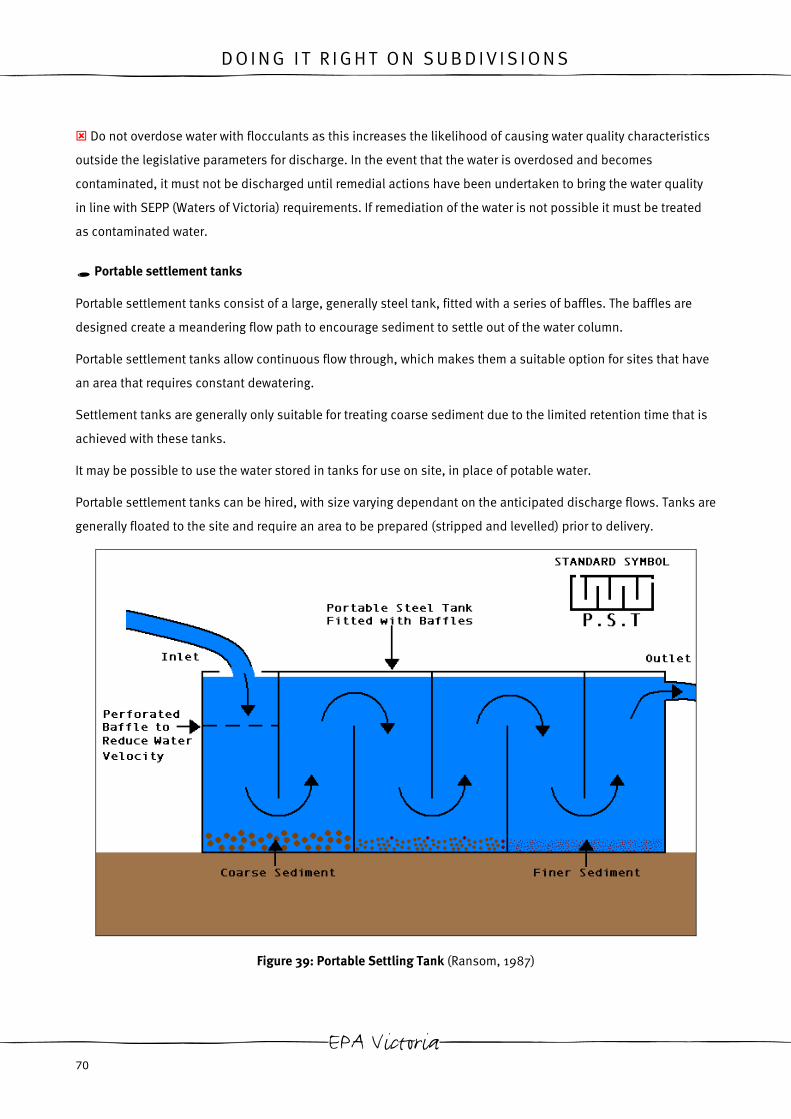
D O I N G I T R I G H T O N S U B D I V I S I O N S
Do not overdose water with flocculants as this increases the likelihood of causing water quality characteristics
outside the legislative parameters for discharge. In the event that the water is overdosed and becomes
contaminated, it must not be discharged until remedial actions have been undertaken to bring the water quality
in line with SEPP (Waters of Victoria) requirements. If remediation of the water is not possible it must be treated
as contaminated water.
Portable settlement tanks
Portable settlement tanks consist of a large, generally steel tank, fitted with a series of baffles. The baffles are
designed create a meandering flow path to encourage sediment to settle out of the water column.
Portable settlement tanks allow continuous flow through, which makes them a suitable option for sites that have
an area that requires constant dewatering.
Settlement tanks are generally only suitable for treating coarse sediment due to the limited retention time that is
achieved with these tanks.
It may be possible to use the water stored in tanks for use on site, in place of potable water.
Portable settlement tanks can be hired, with size varying dependant on the anticipated discharge flows. Tanks are
generally floated to the site and require an area to be prepared (stripped and levelled) prior to delivery.
Figure 39: Portable Settling Tank (Ransom, 1987)
EPA Victoria 70

D O I N G I T R I G H T O N S U B D I V I S I O N S
Contaminated water
Where water is contaminated it must not be discharged to stormwater or surface water bodies.
Volumes of water less than 2000L should be disposed of in accordance with section 5.4, for waste disposal
guidance.
For volumes of contaminated water greater than 2000L the local water authority may be contacted to investigate
whether the water meets the requirements for discharge to sewer. On site treatment may also be appropriate for
large volumes of contaminated water. If neither of these options is viable it will be necessary to dispose of the
water as per volumes less than 2000L. (CCF and EPA Victoria, 2001)
Guidelines for Environmental Management 71

D O I N G I T R I G H T O N S U B D I V I S I O N S
4.5 Performance Summary of Environmental Protection Measures for Erosion and Sediment Management
Soil Type Flow Type Erosion and Sediment Control Type Cost Control Measure
Course Fine Dispersive Sheet Concentrated In
Stream
Diverts
Run-off
Protects
Soil
Surface
Reduces
Run-off
Velocity
Filters
/Settles
Sediment
Installation Maintenance Lifecycle
Erosion
prevention
Stage works S S S S S S N VH H H N N N
Catch drains S S S S S US VH N N N M/H L M
Cut-off drains S S S S US US H N L/M N L/M N/A L/M
Earth banks S S S S S US VH N N N M/H L M
Level spreader S S S US S US H N H N M/H L/M M
Piped down slope
water diversion
S S S US S US VH VH N N H M M/H
EPA Victoria 72

D O I N G I T R I G H T O N S U B D I V I S I O N S
Soil Type Flow Type Erosion and Sediment Control Type Cost Control Measure
Course Fine Dispersive Sheet Concentrated In
Stream
Diverts
Run-off
Protects
Soil
Surface
Reduces
Run-off
Velocity
Filters
/Settles
Sediment
Installation Maintenance Lifecycle
Lined channel
down slope water
diversion
S S S US S US VH VH N N H M M/H
Energy dissipater S S S US S US H H VH L M/H M M
Retain existing
vegetation
S S S S S S N VH H M N N N
Temporary fence
areas of retained
vegetation
S S S S S S N VH H M M L/M M
S= Suitable, S*= Limited Performance, U= Unsuitable
N= Negligible, L= Low, M= Moderate, H= High, VH= Very High, N/A= Not Applicable
Guidelines for Environmental Management 73

D O I N G I T R I G H T O N S U B D I V I S I O N S
4.5 Performance Summary of Environmental Protection Measures for Erosion and Sediment Management (cont.)
Soil Type Flow Type Erosion and Sediment Control Type Cost Control Measure
Course Fine Dispersive Sheet Concentrated In
Stream
Diverts
Run-off
Protects
Soil
Surface
Reduces
Run-off
Velocity
Filters
/Settles
Sediment
Installation Maintenance Lifecycle
Erosion
prevention cont.
Stabilisation
matting
S S S S S US N VH L/M L H L/M M/H
Grassing- hand
sown
S S S S S *establish
prior to flow
US N M/H M/H L/M M/H L/M M
Grassing-
hydroseeding
S S S S S *establish
prior to flow
US N M/H M/H L/M H/VH L H
Grassing-
hydromulching
S S S S S *establish
prior to flow
US N H/VH M/H L/M VH L H/VH
Mulch S S US S US US N H/VH M/H L H/VH L H
EPA Victoria 74

D O I N G I T R I G H T O N S U B D I V I S I O N S
Soil Type Flow Type Erosion and Sediment Control Type Cost Control Measure
Course Fine Dispersive Sheet Concentrated In
Stream
Diverts
Run-off
Protects
Soil
Surface
Reduces
Run-off
Velocity
Filters
/Settles
Sediment
Installation Maintenance Lifecycle
Progressive
revegetation
S S S S S S N VH M/H L/M N L*only if
damaged
N
Rock armouring S S S* With
Geotextile
S S S N VH H M/H H M M/H
Ripping smooth
soil surfaces
S S* US S US US N N M L M M M
S= Suitable, S*= Limited Performance, U= Unsuitable
N= Negligible, L= Low, M= Moderate, H= High, VH= Very High, N/A= Not Applicable
Guidelines for Environmental Management 75

D O I N G I T R I G H T O N S U B D I V I S I O N S
4.5 Performance Summary of Environmental Protection Measures for Erosion and Sediment Management (cont.)
Soil Type Flow Type Erosion and Sediment Control Type Cost Control Measure
Course Fine Dispersive Sheet Concentrated In
Stream
Diverts
Run-off
Protects
Soil
Surface
Reduces
Run-off
Velocity
Filters
/Settles
Sediment
Installation Maintenance Lifecycle
Sediment
retention
structures
Straw bales S S* US S US US L/M N L/M M M/H M/H M/H
Silt fence S S* US S US US L N L M M M M
Grass filter strip S S* US S S US N N M/H M N L/M L
Straw bale/ silt
fence sediment
trap
S S* US S S US M N M/H M/H M/H M/H M/H
Rock groyne/
bund
S S* US S S S* N N H M/H M/H M M
Coir logs S S* US S S US M N H M H/VH L/M M
EPA Victoria 76

D O I N G I T R I G H T O N S U B D I V I S I O N S
Soil Type Flow Type Erosion and Sediment Control Type Cost Control Measure
Course Fine Dispersive Sheet Concentrated In
Stream
Diverts
Run-off
Protects
Soil
Surface
Reduces
Run-off
Velocity
Filters
/Settles
Sediment
Installation Maintenance Lifecycle
Synthetic straw
bale replacements
and logs
S S* US S S S* N N H M/H H/VH L/M M
Straw bale and
stone sediment
trap
S S* US S S US N N M M M/H M M
Silt fence
sediment trap
S S* US S S US N N L M M M M
Sediment basin S S* US S S US N N H H VH H VH
Floating silt
curtain
S S* US US US S N N N M/H H L M/H
S= Suitable, S*= Limited Performance, U= Unsuitable
N= Negligible, L= Low, M= Moderate, H= High, VH= Very High, N/A= Not Applicable
Guidelines for Environmental Management 77

D O I N G I T R I G H T O N S U B D I V I S I O N S
4.5 Performance Summary of Environmental Protection Measures for Erosion and Sediment Management (cont.)
Soil Type Flow Type Erosion and Sediment Control Type Cost Control Measure
Course Fine Dispersive Sheet Concentrated In
Stream
Diverts
Run-off
Protects
Soil
Surface
Reduces
Run-off
Velocity
Filters
/Settles
Sediment
Installation Maintenance Lifecycle
Synthetic
composite silt
curtain
S S* S* US US S N N N M/H H L M/H
Sediment
retention
structure (cont).
Synthetic
composite
standpipe filter
S S* S* N/A N/A N/A N N N M/H M/H L M
Sandbag sediment
barrier
S US US US S US N N M L/M L/M L/M L/M
Gravel sausage S S* US US S US N N M M L/M L/M L/M
Block and gravel
kerb inlet filter
S US US US S US N N N M M L/M M
EPA Victoria 78

D O I N G I T R I G H T O N S U B D I V I S I O N S
Soil Type Flow Type Erosion and Sediment Control Type Cost Control Measure
Course Fine Dispersive Sheet Concentrated In
Stream
Diverts
Run-off
Protects
Soil
Surface
Reduces
Run-off
Velocity
Filters
/Settles
Sediment
Installation Maintenance Lifecycle
Sediment
Retention
Structure (cont.)
Silt fence under
grate
S S* US S S US N N N M L M/H M
Temporary pit lid S S* US S S US N N N M/H M/H L/M M
Silt fence drop
inlet protection
S S* US S US US N N N M L/M M M
Straw bale drop
inlet protection
S S* US S S* US N N N M L/M M/H M
Straw bale and silt
fence drop inlet
protection
S S* US S S US N N N M/H L/M M M
S= Suitable, S*= Limited Performance, U= Unsuitable
N= Negligible, L= Low, M= Moderate, H= High, VH= Very High, N/A= Not Applicable
Guidelines for Environmental Management 79

D O I N G I T R I G H T O N S U B D I V I S I O N S
4.5 Performance Summary of Environmental Protection Measures for Erosion and Sediment Management (cont.)
Soil Type Flow Type Erosion and Sediment Control Type Cost Control Measure
Course Fine Dispersive Sheet Concentrated In
Stream
Diverts
Run-off
Protects
Soil
Surface
Reduces
Run-off
Velocity
Filters
/Settles
Sediment
Installation Maintenance Lifecycle
Mesh and
aggregate drop
inlet protection
S US US S US US N N N M L/M M M
Culvert entry
gravel filter
S US US S S US N N N M L/M M M
Silt filter bung S S S* S S US N N N H/VH M L/M M
Keeping mud off
roads
Minimise number
of access points
S S S N/A N/A N/A N N N N N N N
Minimise wet
weather vehicle
access
S S S N/A N/A N/A N N N N L L L
EPA Victoria 80

D O I N G I T R I G H T O N S U B D I V I S I O N S
Soil Type Flow Type Erosion and Sediment Control Type Cost Control Measure
Course Fine Dispersive Sheet Concentrated In
Stream
Diverts
Run-off
Protects
Soil
Surface
Reduces
Run-off
Velocity
Filters
/Settles
Sediment
Installation Maintenance Lifecycle
Rumble grid S S* S* N/A N/A N/A N N N N VH M H
Gravel access
point
S S* S* N/A N/A N/A N N N N VH M H
Physical scrape of
material from
Vehicles
S* S* S* N/A N/A N/A N N N N M/L VH M/H
Street sweeper S S* S* N/A N/A N/A N N N N N/A H H
Dewatering
Controls
S= Suitable, S*= Limited Performance, U= Unsuitable
N= Negligible, L= Low, M= Moderate, H= High, VH= Very High, N/A= Not Applicable
Guidelines for Environmental Management 81

D O I N G I T R I G H T O N S U B D I V I S I O N S
4.5 Performance Summary of Environmental Protection Measures for Erosion and Sediment Management (cont.)
Soil Type Flow Type Erosion and Sediment Control Type Cost Control Measure
Course Fine Dispersive Sheet Concentrated In
Stream
Diverts
Run-off
Protects
Soil
Surface
Reduces
Run-off
Velocity
Filters
/Settles
Sediment
Installation Maintenance Lifecycle
Water quality monitoring- out sourced
S S S N/A N/A N/A N/A N/A N/A N/A N/A N/A H/VH
Water quality monitoring-self sampled, processed by lab.
S S S N/A N/A N/A N/A N/A N/A N/A N/A N/A H
Water quality monitoring- self sampled and processed
S S S N/A N/A N/A N/A N/A N/A N/A N/A N/A M
Pump sacks S S* US N/A N/A N/A N N N H M L/M M
Flocculants S S S N/A N/A N/A N N N VH N/A N/A M/H
Settling tanks S S* US N/A N/A N/A N N N M H/VH M H
S= Suitable, S*= Limited Performance, U= UnsuitableN= Negligible, L= Low, M= Moderate, H= High, VH= Very High, N/A= Not Applicable
Table 7: Performance Summary of Environmental Protection Measures for Sediment and Erosion Management
EPA Victoria 82

D O I N G I T R I G H T O N S U B D I V I S I O N S
5 . W A S T E
Mismanagement of waste on site has the potential to transport litter and other waste materials off site by wind or
water. The environmental protection measures outlined in this section may be used to mitigate these effects.
5.1 Minimising the production of waste material
Reduce
The amount of waste produced by the site may be reduced by:
• not over ordering materials;
• negotiating with suppliers to take back any materials that are not used;
• using prefabricated materials. (Arcadian Solutions, 2002)
Reuse
Some waste items may be converted to useable items that may be utilised on the site they are derived from or on
other sites.
Some convenient reuse options include:
• chipping trees to produce mulch;
• suitable spoil may be used on other sites, or future stages of subdivision as fill;
• retained topsoil may be respread at the end of earthworks. It is indigenous to the site and reduces
transportation costs. In particular retain the top 150mm as it contains the most organic component of the
topsoil.
• Captured run-off may be used for dust suppression or construction activities to reduce the consumption of
mains water;
• safety, survey and other apparatus may be collected and reused on other sites or future stages.
Recycle
Separate materials such as concrete, timber, metal, green waste, oils, topsoil and excess spoil from other waste
items for recycling.
Place clear signage on recycling bins, skips or stockpile areas to ensure everyone on site knows which materials
are to be placed in them. This ensures that materials for recycling are not contaminated with other waste, which
may prevent them from being recycled (Arcadian Solutions, 2002).
Guidelines for Environmental Management 83

D O I N G I T R I G H T O N S U B D I V I S I O N S
Where possible select products for purchase that have been produced from recycled materials. For example
recycled crushed concrete may be appropriate for use on subdivision sites as aggregate for road base. It can
provide a better base product due to its superior binding properties and performs in a manner similar to that of
1.5 per cent cement stabilised crushed rock. It is also cheaper than virgin rock as prices are calculated on weight
and crushed concrete is 10 per cent lighter (Arcadian Solutions, 2002).
See EcoRecycle’s website at www.ecorecycle.vic.gov.au for full details on items that may be recycled, recycling
facilities and where to purchase recycled products.
5.2 Containing waste material on site
Solid waste
Designate a stockpile area or use a skip to store solid waste until a sufficient amount has accumulated for
removal.
Locating the waste collection area close to the site sheds is often a good technique, as it can easily be identified
when enough waste has accumulated for disposal.
General litter
General litter, particularly litter that is able to be windblown, should be stored in a lidded bin from which material
cannot escape.
Bins should be located near site offices and crib sheds, particularly in areas where food is consumed.
Bins must be regularly emptied to ensure litter does not overflow.
Photo 38: Overflowing Bin
EPA Victoria 84

D O I N G I T R I G H T O N S U B D I V I S I O N S
Washings, residues, slurries and other water contaminated by wash up
Wash up materials including concrete, paint and brick cutting slurry in a designated area.
Washings/ slurry from concrete trucks is frequently the key material that requires a clean up area on a subdivision
site. Run-off contaminated with concrete is of environmental concern as it is alkaline. Designate an area on site
for concrete trucks to be washed out with the following characteristics:
• the area should be located away from drainage lines, stormwater inlets, waterways, areas of significant flora
and fauna and other sensitive areas identified on site;
• the area should be appropriately bunded to contain all contaminated water from washing up (See Section 6.1
for bunding details);
• placing this area near the site exit will encourage drivers to use it due to accessibility (ie. they must pass it on
the way out). It may be necessary to inform the concrete supplier to inform his drivers of the presence of the
wash out area. It is often impractical to inform every driver that comes on site.
• It may be necessary to sign the area for easy identification by subcontractors;
• small amounts of concrete washings/slurry may be placed on an impervious liner until the water evaporates.
Concrete residue may then be disposed of as solid waste. (VSAP Building Construction Sites Project Group,
2003)
In the event that painting, brick cutting or other items require wash up, resulting in contaminated run-off, the
designated area can also be utilised.
Tem
con
Photo 39: Designated Concrete Washout Area
Temporary fencing
porary fencing of the site boundary or early installation of boundary fencing can act as a secondary
tainment measure for litter. Temporary fencing of the site compound may be appropriate, particularly if the
Guidelines for Environmental Management 85
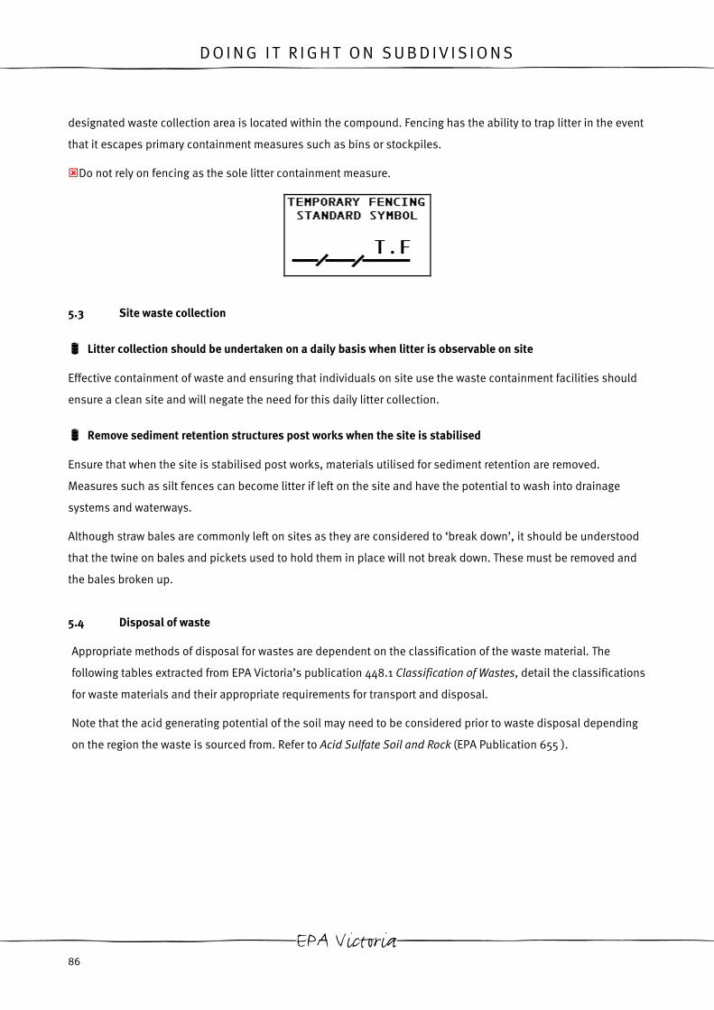
D O I N G I T R I G H T O N S U B D I V I S I O N S
designated waste collection area is located within the compound. Fencing has the ability to trap litter in the event
that it escapes primary containment measures such as bins or stockpiles.
Do not rely on fencing as the sole litter containment measure.
5.3 Site waste collection
Litter collection should be undertaken on a daily basis when litter is observable on site
Effective containment of waste and ensuring that individuals on site use the waste containment facilities should
ensure a clean site and will negate the need for this daily litter collection.
Remove sediment retention structures post works when the site is stabilised
Ensure that when the site is stabilised post works, materials utilised for sediment retention are removed.
Measures such as silt fences can become litter if left on the site and have the potential to wash into drainage
systems and waterways.
Although straw bales are commonly left on sites as they are considered to ‘break down’, it should be understood
that the twine on bales and pickets used to hold them in place will not break down. These must be removed and
the bales broken up.
5.4 Disposal of waste
Appropriate methods of disposal for wastes are dependent on the classification of the waste material. The
following tables extracted from EPA Victoria’s publication 448.1 Classification of Wastes, detail the classifications
for waste materials and their appropriate requirements for transport and disposal.
Note that the acid generating potential of the soil may need to be considered prior to waste disposal depending
on the region the waste is sourced from. Refer to Acid Sulfate Soil and Rock (EPA Publication 655 ).
EPA Victoria 86

D O I N G I T R I G H T O N S U B D I V I S I O N S
The following is taken from Classification of Wastes (EPA Publication 448.1)
TYPE DESCRIPTION EPA REQUIREMENTS FOR
OFFSITE TREATMENT/
DISPOSAL
MANAGEMENT OPTIONS
FILL MATERIAL Soil (sand, clay and
silt), gravel, rock;
contamination levels
must not be greater
than listed in Table 2.
• No licence required,
however disposal must
not give rise to any offsite
impact
• Fill material needs
(site filling/
levelling)
• Landfill
SOLID INERT Demolition material,
concrete, bricks,
timber, plastic, glass,
metals, bitumen, trees,
shredded tyres.
• Non-municipal landfills
must be licensed
• When disposing to
municipal landfill serving
>5000 persons site must
be liscenced1
• Re-use
• Recycling
• Landfill
PUTRESCIBLE Domestic garbage,
commercial waste,
vegetables,
supermarket
processing,
delicatessans, butchers
etc., garden clippings/
prunings
• Non-municipal landfills
must be licensed
• When disposing to
municipal landfill serving
>5000 persons site must
be liscenced1
• Composting
• Landfill
• Stock food2
• Incineration
LOW LEVEL
CONTAMINATED
SOIL
Soils with
contamination levels
and elutriable fraction
less than set out in
Table 3.
• Disposal to licensed site1
• EPA transport certificate
must be used
• Vehicles must hold EPA
permit (some exemptions
apply)
• On-site remediation
• Off-site remediation
• Landfill
PRESCRIBED WASTE Listed in the Prescribed
Waste Regulations and
Table 4
• Disposal to licensed site1
• EPA transport certificate
must be used
Various treatment and
disposal methods
dependant on waste eg:
Guidelines for Environmental Management 87
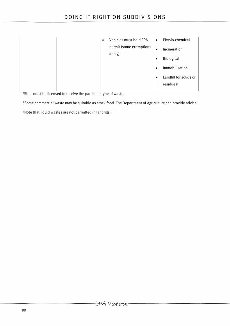
D O I N G I T R I G H T O N S U B D I V I S I O N S
• Vehicles must hold EPA
permit (some exemptions
apply)
• Physio-chemical
• Incineration
• Biological
• Immobilisation
• Landfill for solids or
residues3
1Sites must be licensed to receive the particular type of waste.
2Some commercial waste may be suitable as stock food. The Department of Agriculture can provide advice.
3Note that liquid wastes are not permitted in landfills.
EPA Victoria 88

D O I N G I T R I G H T O N S U B D I V I S I O N S
Table 2
Maximum concentrations of contaminants allowed in soil to be disposed of as fill material
Table 3
Maximum contaminant concentrations and elutriable fractions allowed in soil to be disposed of as contaminated soils (low level).
Contaminant Maximum Concentration
(total) mg/kg dry weight
Contaminant Maximum Concentration (total) mg/kg
dry weight
Elutriable Fraction
(pH 5.0 extract) g/m3
Arsenic 30 Arsenic 300 5.0 Cadmium 5 Cadmium 50 0.5 Chromium 250 Chromium 2500 5.0 Copper 100 Copper 1000 10 Cobalt 50 Cobalt 500 - Lead 300 Lead 3000 5.0 Mercury 2 Mercury 20 0.1 Molybdenum 40 Molybdenum 400 - Nickel 100 Nickel 1000 - Tin 50 Tin 500 - Selenium 10 Selenium 100 1.0 Zinc 500 Zinc 5000 50 Cyanide 50 Cyanide 500 10 Fluoride 450 Fluoride 4500 150 Phenols 1 Phenols 10 - Monocyclic Aromatic Hydrocarbons
7 Monocyclic Aromatic Hydrocarbons
70 -
Polycyclic Aromatic Hydrocarbons
20 Polycyclic Aromatic Hydrocarbons
200 -
Total Petroleum Hydrocarbons (C6
to C9)
100 Total Petroleum Hydrocarbons (C6
to C9)
1000 -
Total Petroleum Hydrocarbons (>C9)
1000 Total Petroleum Hydrocarbons (>C9)
10000 -
Organochlorine Compounds
1 Organochlorine Compounds
10 -
Guidelines for Environmental Management 89

D O I N G I T R I G H T O N S U B D I V I S I O N S
Table 8: EPA Victoria Waste
Classification, Transport and
Disposal Details - Classifcation
of Wastes(EPA Victoria
Publication 448.1)
General Prescribed Wastes
Grease interceptor trap effluent arising from domestic premises
Prescribed Industrial Wastes
Acids in a solid form and acidic solutions with a pH value of 4 or less
Alkaline solids and alkaline solutions with a pH value of 9 or more
Animal and vegetable oils and derivatives
Animal effluent and residues including abattoir effluent, poultry and fish processing wastes
Antimony and antimony compounds
Any congener of polychlorinated dibenzo-furans (PCDFs)
Any congener of polychlorinated dibenzo-p-dioxins (PCDDs)
Arsenic and arsenic compounds
Asbestos (all forms)
Barium and barium compounds
Beryllium and beryllium compounds
Boron and boron compounds
Cadmium and cadmium compounds
Caustic neutralised wastes containing metallic constituents
Ceramic based fibres with physico-chemical characteristics similar to those of asbestos
Chromium compounds
Clinical and related wastes (not otherwise specified)
Cobalt and cobalt compounds
Contaminated soils (low level) with contaminant concentrations
exceeding those specified in Table 2 of Publication 448 entitled “Classification of Wastes” published by the Authority in 1995 as amended from time to time or republished by the Authority but with contaminant concentrations and elutriable fractions not exceeding those specified in Table 3 of that publication as amended from time to time or republished by the Authority
Contaminated soils with contaminant concentrations or elutriable fractions exceeding those specified in Table 3 of Publication 448 entitled “Classification of Wastes” published by the Authority in 1995 as amended from time to time or republished by the Authority
Copper compounds
Cyanides (inorganic)
Cyanides (organic)
Detergents and surface active agents (surfactants)
Filter cake
Fly ash
Grease interceptor trap effluent
Halogenated organic chemicals (not otherwise specified)
Halogenated organic solvents
Heterocyclic organic compounds containing oxygen, nitrogen or sulphur
Highly odorous organic chemicals (including mercaptans and acrylates)
Highly reactive chemicals (not otherwise specified)
Inert sludges or slurries
Inorganic chemicals (not otherwise specified)
Inorganic fluorine compounds (excluding calcium fluoride)
Inorganic sulphur containing compounds
Isocyanate compounds
Lead and lead compounds
Mercury and mercury compounds
Metal carbonyls
Nickel compounds
Non-halogenated organic chemicals (not otherwise specified)
Non-toxic salts
Organic solvents (excluding halogenated solvents)
Oxidising agents including chlorates, perchlorates, peroxides
Phenol and phenol compounds (including halogenated phenols)
Phosphorus and phosphorous compounds
Prescribed industrial wastes that are encapsulated, chemically fixed, solidified or polymerised
Residues from industrial waste treatment or disposal operations (not otherwise specified) including filter backwash waters
Selenium and selenium compounds
Silver and silver compounds
Spent catalysts
Tannery wastes (not otherwise specified) including leather dust, ash, sludges and flours
Tellurium and tellurium compounds
Textile effluent and residues (not otherwise specified)
Thallium and thallium compounds
Vanadium compounds
Vegetable, fruit, food processing effluent
Vehicle, machinery and industrial washwaters with or without detergents
Waste chemical substances arising from research and development or teaching activities (not otherwise specified), that are new or unidentified substances with unknown human health or environmental effects
Waste from the production, formulation and use of:
EPA Victoria 90

D O I N G I T R I G H T O N S U B D I V I S I O N S
biocides and phytopharmaceuticals (not otherwise specified)
inks, dyes, pigments, paints, lacquers and varnish (not otherwise specified)
organic solvents (not otherwise specified)
photographic chemicals and processing materials
resins, latex, plasticisers, glues and adhesives (not otherwise specified) excluding solid inert polymeric materials
wood-preserving chemicals (not otherwise specified)
pharmaceutical products (not otherwise specified)
Waste oils unfit for their original intended use
Waste oil and water mixtures or emulsions and hydrocarbon and water mixtures or emulsions
Waste resulting from surface treatment of metals and plastics
Waste substances or articles containing or contaminated with polychlorinated biphenyls (PCBs) or polybrominated biphenyls (PBBs)
Waste tarry residues arising from refining, distillation, and any pyrolytic treatment
Wastes of an explosive nature not subject to any other legislation including azides
Wool scouring wastes
Zinc compounds
Guidelines for Environmental Management 91


D O I N G I T R I G H T O N S U B D I V I S I O N S
5.5 Performance Summary of Environmental Protection Measures for Waste Management
Containment Effectiveness Control Measure
General Litter Solid Waste Washing/
Residues
Waste Minimisation Potential Cost
Reduce N/A N/A N/A H
Reuse N/A N/A N/A M/H
Recycle N/A N/A N/A M
* Minimisation measures have
the potential to result in
savings in material purchase
and disposal costs.
Containment measures
Stockpile N M/H N N/A L
Skip (with ld) H H N N/A M
Bin (with lid) H N N N/A L
Wash up area N N H N/A L/M
Waste minimisation
Guidelines for Environmental Management 93

D O I N G I T R I G H T O N S U B D I V I S I O N S
Containment Effectiveness Control Measure
General Litter Solid Waste Washing/
Residues
Waste Minimisation Potential Cost
Temporary fencing L L N N/A H
Disposal
Landfill- fill material N/A N/A N/A N M
Landfill- solid inert N/A N/A N/A N M/H
Landfill- putrescible N/A N/A N/A N M/H
Landfill- low level contaminated
waste
N/A N/A N/A N H/VH
Landfill- prescribed waste N/A N/A N/A N VH
N= Negligible, L= Low, M= Moderate, H= High, VH= Very High, N/A= Not Applicable
Table 9: Performance Summary of Environmental Protection Measures for Waste Management
EPA Victoria 94
D O I N G I T R I G H T O N S U B D I V I S I O N S
6 . C H E M I C A L S
Mismanagement of chemicals on site has the potential to contaminate surface waterways, leach toxins into the
groundwater, result in reduced fitness or mortality of flora and fauna and result in OH&S issues. The
environmental protection measures outlined in this section may be used to mitigate these effects.
6.1 Storage area
Location
Chemicals and fuels should always be stored in an area where spills cannot result in any environmental damage.
Chemicals and fuels should be located away from drainage lines, stormwater inlets, waterways, areas of
significant flora and fauna and other sensitive areas. When siting chemical and fuel storage areas, the slope of
the site and the potential flow pathways to sensitive areas (such as those listed above) should be taken into
account. As an absolute minimum, chemicals and fuels should be stored at least 10maway from sensitive areas.
Bunding
Bunding provides a secondary containment measure in the event of a spill.
Bunded areas should have the following characteristics:
Materials should be impervious to and compatible with the chemicals to be contained.
The floor should be graded towards a sump to enable collection of spilt material.
Different chemicals should not be stored together in the same bunded area.
The area should be undercover where possible.
Where the area is not undercover the bund height should be greater than150mm.
The capacity of a bunded area containing tank/s should be sufficient to hold 100 per cent of the capacity of
the largest tank, plus 10 per cent of the capacity of the second largest tank.
The capacity of a bunded area for refuelling should be 100 per cent of the largest compartment of any tank
vehicle using the facility.
Ramps or roll-over bunds should be used where vehicle access is required into the bunded area to maintain
effective bund height.
Run-off should be diverted away from the bunded area and any ponded run-off in the bunded area should be
regularly disposed of. (EPA Victoria Publication 347)
Guidelines for Environmental Management 95

D O I N G I T R I G H T O N S U B D I V I S I O N S
Earth bunds are frequently utilised on subdivision sites due to their cost effectiveness and ease of construction.
However, in the event of a spill the soil within the earthen bund is contaminated and must also be disposed of.
Spills must also be quickly cleaned up with absorbent materials to ensure the spilt material does not leach into
the groundwater. Other bunding methods may be used, dependant on what is appropriate for the site. Photo 40
shows a trailer that has been utilised as a bund for a fuel tank by lining the trailer with an impervious liner.
Portable bunds may be a useful purchase for multi-stage sites requiring an impervious bunded area. These
lightweight, portable bunds can be easily moved to different locations as site works progress, without incurring
costs of constructing new impervious, bunded areas. Portable bunds must be stored on level ground when not in
use so as not to compromise the bund capacity.
Impervious line
Impervious liners
(particularly soils)
Ensure that the typ
contain.
6.2 Refuelli
Designated refu
On sensitive sites
outlined on page 9
for designated ref
96
Photo 40: Lined Trailer Utilised as a Bund
rs
for bunded areas ensure that spills are contained and do not contaminate other material
on site.
e of material selected for the liner, will not be damaged by the chemical it is in place to
ng/ maintenance areas
elling/ maintenance area
it may be necessary to designate a specific refuelling/ maintenance area. The control measures
5 for chemical storage relating to location, bunding and impervious liners may also be applied
uelling/maintenance areas.
EPA Victoria

D O I N G I T R I G H T O N S U B D I V I S I O N S
Figure 40: Designated Refuelling/ Maintenance Area (Figures from EPA Victoria Publication 347)
Mobile refuelling
It may not be practical for some sites to have a designated refuelling area, particularly larger sites (where it may
be impractical to move machinery distances to refuelling areas) or those sites that utilise mobile fuel trucks. In
these cases as a minimum ensure that:
• Refuelling does not take place near drainage lines, stormwater inlets, waterways, areas of significant flora
and fauna and other sensitive areas identified on site.
• A suitable spill kit is kept on the fuel truck or the site spill kit is kept within 10m of refuelling activities.
6.3 Spill clean up
Clean up all spills immediately
Cleaning up spills immediately ensures that contaminated material is not spread around the site to contaminate
other material.
Immediate clean up of spills also ensures that the spilt material does not infiltrate into the ground and
contaminate the groundwater.
Guidelines for Environmental Management 97

D O I N G I T R I G H T O N S U B D I V I S I O N S
Spill kits
Spill kits should be kept on sites where chemicals will be stored. The spill kit should be kept approximately 10m
away from the chemical storage area so that it is accessible in the event of a spill, but safely out of the range of
spills.
Common components of spill kits include; booms, pads, pillows, socks, rolls, floor sweeps, gloves and disposal
bags. These items may be contained in wheelie bins, bags, buckets or drums.
Different spill kits are designed to absorb different materials. Ensure that the spill kit selected for the site is
designed to treat the types of chemicals that are stored on that site.
If a fuel truck without a spill kit on board is periodically on site, the site spill kit should be kept within 10m of the
fuel truck while it undertakes refuelling activities. As a general rule it is far easier to keep a spill kit on the fuel
truck, than to transport the site spill kit around when a fuel truck is on site.
Photo 41: Site Spill Kit (Courtesy of Global Spill Control) Photo 42: Portable Spill
Control)
Training of staff in event of spill
A minimum of two people on site should be trained to act in the event of a spill. These
familiar with:
• the types of chemicals stored on site and their appropriate methods for clean up i
Material safety data sheets (MSDS) should be kept on site and the staff responsib
should be familiar with the location and content of these.
• Components and appropriate use of spill kits (or other appropriate spill containm
if a spill kit is not used).
EPA Victoria 98
Kit (Courtesy of Global Spill
staff should be made
f spilt.
le for clean up of spills
ent and clean up measures

D O I N G I T R I G H T O N S U B D I V I S I O N S
• Who to contact in the event of a spill.
• Methods of disposal of spilt materials.
• Incident reporting.
Disposal of material affected by spills
Where possible collect and reuse spilt materials. Where this is not possible or if the material is contaminated,
collect the spilt material, any material used to absorb the spill and any soil or other materials contaminated by
the spill and dispose of these in accordance with Section 5.4.
Guidelines for Environmental Management 99
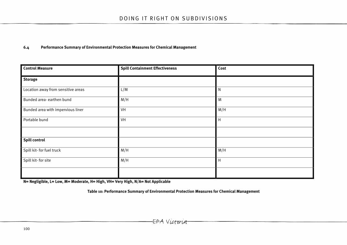
D O I N G I T R I G H T O N S U B D I V I S I O N S
6.4 Performance Summary of Environmental Protection Measures for Chemical Management
Control Measure Spill Containment Effectiveness Cost
Storage
Location away from sensitive areas L/M N
Bunded area- earthen bund M/H M
Bunded area with impervious liner VH M/H
Portable bund VH H
Spill control
Spill kit- for fuel truck M/H M/H
Spill kit- for site M/H H
N= Negligible, L= Low, M= Moderate, H= High, VH= Very High, N/A= Not Applicable
Table 10: Performance Summary of Environmental Protection Measures for Chemical Management
EPA Victoria 100

D O I N G I T R I G H T O N S U B D I V I S I O N S
7 . C O N C L U S I O N
As detailed within this document, successful site environmental management can be achieved by ensuring the
effective management of the key environmental issues of:
• noise,
• dust,
• sediment and erosion,
• waste and
• chemicals,
and any other site specific environmental issues of concern.
Ensure good environmental performance for each of these issues is achieved simply by:
• selecting suitable, site specific environmental protection measures,
• ensuring appropriate installation of protection measures, and
• effectively maintaining on site protection measures.
Ultimately the environmental protection measures outlined within this document can only be viewed as tools.
Successful environmental performance will only be achieved with the integration of these measures into a site
environmental management plan and with a strong commitment to environmental management on the site.
Guidelines for Environmental Management 101

D O I N G I T R I G H T O N S U B D I V I S I O N S
8 . R E F E R E N C E S
ACT Government, 1998, ‘ Erosion and Sediment Control During Land Development’, Canberra
Aquaseeding, No Date, ‘Aquaseeding’, Accessed Online: 4/07/03, www.aquaseeding.com.au
Arcadian Solutions, 2002, ‘The Do’s and Don’ts of Resourceful Construction and Demolition’, Australia
Civil Contractors Federation (CCF) and Environmental Protection Authority Victoria Australia (EPA Victoria), 2001,
‘Environmental Management System’, Victoria
Environment Protection Authority Victoria Australia (EPA Victoria), 1991, ‘Construction Techniques for Sediment
Pollution Control’, Report No. 275, Victoria
Environment Protection Authority Victoria Australia (EPA Victoria), 1992, ‘Bunding Guidelines’, Report No. 347,
Victoria
Environment Protection Authority Victoria Australia (EPA Victoria), 1995, ‘Classification of Wastes’, Report No.
448.1, Victoria
Environment Protection Authority Victoria Australia (EPA Victoria), 1995, ‘ Environmental Guidelines for Major
Construction Sites’, Report No. 480, Victoria
Environment Protection Authority Victoria Australia (EPA Victoria), 1999, ‘ Acid Sulfate soil and rock, Report No.
655, Victoria
Environment Protection Authority Victoria Australia (EPA Victoria), 2003, ‘Sediment in Streams and Rivers’,
Victoria
Government of British Colombia, (No Date), ‘Wheel Washer’,
http://www.em.gov.bc.ca/Mining/MiningStats/Aggregate%20BMP%20Handbook/BMPs/Wheel%20Washer.pdf,
Ministry of Energy and Mines
Kerr, G., ‘Rainstorm Dust Control” Accessed Online: 11/06/03, www.rainstorm.com.au , Australia
Local Government Professionals (LG Pro), 2002, ‘Specification for the Protection of Stormwater Quality’, CD
Reference
Melbourne Water, July 2002 ‘Constructed Wetland Systems: Design Guidelines for Developers’, Victoria
NSW Dept. of Housing, 1998, ‘Managing Urban Stormwater: Soils and Construction’, Edition 3, New South Wales
NSW Dept. of Housing, 2003, ‘Managing Urban Stormwater: Soils and Construction’, Edition 4 (Draft), New South
Wales
Ransom, M.J., 1987, ‘Control of Erosion on Construction Sites’, Department of Conservation Forests and Land
EPA Victoria 102

D O I N G I T R I G H T O N S U B D I V I S I O N S
Schneider, S.P., 2001, ‘Quieting Your Construction Site’, Accessed Online: 10/06/03, www.lhsfna.org, North
America
Soil Conservation Authority, 1979, ‘Guidelines for Minimising Soil Erosion and Sedimentation from Construction
Sites in Victoria’, Melbourne
Stormwater Committee, 1999, ‘Urban Stormwater Best Practice Environmental Management Guidelines’, Victoria
Treemax, No Date, ‘Treemax: Erosion Control Solutions’, Accessed Online: 17/07/03,
www.treemax.com.au/erosion.html, Victoria
TurfMaker, 2000, ‘HydroMulching and Hydroseeding Defined: A Grass Planting Process’, Accessed Online:
6/13/03, www.turfmaker.com
Victoria Government Gazette, 2003, ‘State Environmental Protection Policy (Waters of Victoria)’, No,S 107, Victoria
VSAP Building Construction Sites Project Group, 2003, ‘Keeping Our Stormwater Clean’, Victoria
University of Nevada, Last updated: 02 April 2002, ‘Dust Suppressant’, Accessed Online: 11/06/03,
www.ce.unlv.edu/~piechota/wrl/dust.htm
US EPA, Last Updated: 12 February 2003, ‘Construction Site Storm Water Runoff Control’, Accessed Online:
29/07/03, http://cfpub.epa.gov/npdes/stormwater/menuofbmps/con_site.cfm, USA
Guidelines for Environmental Management 103