Embed Size (px)
Citation preview
88 COMMUNICATIONS OF THE ACM | SEPTEMBER 2016 | VOL. 59 | NO. 9
Jupiter Rising: A Decade of Clos Topologies and Centralized Control in Google’s Datacenter NetworkBy Arjun Singh, Joon Ong, Amit Agarwal, Glen Anderson, Ashby Armistead, Roy Bannon, Seb Boving, Gaurav Desai, Bob Felderman, Paulie Germano, Anand Kanagala, Hong Liu, Jeff Provost, Jason Simmons, Eiichi Tanda, Jim Wanderer, Urs Hölzle, Stephen Stuart, and Amin Vahdat
AbstractWe present our approach for overcoming the cost, operational complexity, and limited scale endemic to datacenter net-works a decade ago. Three themes unify the five genera-tions of datacenter networks detailed in this paper. First, multi-stage Clos topologies built from commodity switch silicon can support cost-effective deployment of building-scale networks. Second, much of the general, but complex, decentralized network routing and management protocols supporting arbitrary deployment scenarios were overkill for single-operator, pre-planned datacenter networks. We built a centralized control mechanism based on a global configura-tion pushed to all datacenter switches. Third, modular hard-ware design coupled with simple, robust software allowed our design to also support inter-cluster and wide-area net-works. Our datacenter networks run at dozens of sites across the planet, scaling in capacity by 100x over 10 years to more than 1 Pbps of bisection bandwidth. A more detailed version of this paper is available at Ref.21
1. INTRODUCTIONFrom the beginning, Google built and ran an internal cloud for all of our internal infrastructure services and external-facing applications. This shared infrastructure allowed us to run services more efficiently through statistical multiplexing of the underlying hardware, reduced operational overhead by allowing best practices and management automation to apply uniformly, and increased overall velocity in delivering new features, code libraries, and performance enhancements to the fleet.
We architect all these cloud services and applications as large-scale distributed systems.3, 6, 7, 10, 13 The inherent distributed nature of our services stems from the need to scale out and keep pace with an ever-growing global user population. Our services have substantial bandwidth and low-latency requirements, making the datacenter network a key piece of our infrastructure. Ten years ago, we found the cost and operational complexity associated with traditional datacenter network architectures to be prohibitive. Maximum network scale was limited by the cost and capacity of the highest-end switches available at any point in time.23 Bandwidth demands in the datacenter
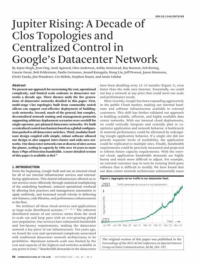
have been doubling every 12–15 months (Figure 1), even faster than the wide area Internet. Essentially, we could not buy a network at any price that could meet our scale and performance needs.
More recently, Google has been expanding aggressively in the public Cloud market, making our internal hard-ware and software infrastructure available to external customers. This shift has further validated our approach to building scalable, efficient, and highly available data center networks. With our internal cloud deployments, we could vertically integrate and centrally plan to co-optimize application and network behavior. A bottleneck in network performance could be alleviated by redesign-ing Google application behavior. If a single site did not provide requisite levels of availability, the application could be replicated to multiple sites. Finally, bandwidth requirements could be precisely measured and projected to inform future capacity requirements. With the exter-nal cloud, application bandwidth demands are highly bursty and much more difficult to adjust. For example, an external customer may in turn be running third party software that is difficult to modify. We have found that our data center network architecture substantially eases
The original version of this paper was published in the Proceedings of the 2015 ACM Conference on Special Interest Group on Data Communication, ACM, 183–197.
Jul ‘08
1x
50x
Jun ‘09
Agg
rega
te t
raffi
c
May ‘10 Apr ‘11 Mar ‘12 Feb ‘13 Dec ‘13 Nov ‘14
Time
Traffic generated by servers in out datacenters
Figure 1. Aggregate server traffic in our datacenter fleet.
DOI:10.1145/2975159
SEPTEMBER 2016 | VOL. 59 | NO. 9 | COMMUNICATIONS OF THE ACM 89
the management overhead of hosting external applica-tions while simultaneously delivering new levels of per-formance and scale for Cloud customers.
Inspired by the community’s ability to scale out comput-ing with parallel arrays of commodity servers, we sought a similar approach for networking. This paper describes our experience with building five generations of custom data center network hardware and software by leveraging commodity hardware components, while addressing the control and management requirements introduced by our approach. We used the following principles in construct-ing our networks:
Clos topologies: To support graceful fault tolerance, increase the scale/bisection of our datacenter networks, and accommodate lower radix switches, we adopted Clos topol-ogies1, 9, 15 for our datacenters. Clos topologies can scale to nearly arbitrary size by adding stages to the topology, princi-pally limited by failure domain considerations and control plane scalability. They also have substantial in-built path diversity and redundancy, so the failure of any individual element can result in relatively small capacity reduction. However, they introduce substantial challenges as well, including managing the fiber fanout and more complex routing across multiple equal-cost paths.
Merchant silicon: Rather than use commercial switches targeting small-volume, large feature sets and high reliabil-ity, we targeted general-purpose merchant switch silicon, commodity priced, off the shelf, switching components. To keep pace with server bandwidth demands which scale with cores per server and Moore’s law, we emphasized bandwidth density and frequent refresh cycles. Regularly upgrading network fabrics with the latest generation of commodity switch silicon allows us to deliver exponential growth in bandwidth capacity in a cost-effective manner.
Centralized control protocols: Control and management become substantially more complex with Clos topologies because we dramatically increase the number of discrete switching elements. Existing routing and management pro-tocols were not well-suited to such an environment. To con-trol this complexity, we observed that individual datacenter switches played a pre-determined forwarding role based on the cluster plan. We took this observation to one extreme by collecting and distributing dynamically changing link state information from a central, dynamically elected, node in the network. Individual switches could then calculate forward-ing tables based on current link state relative to a statically configured topology.
Overall, our software architecture more closely resembles control in large-scale storage and compute platforms than traditional networking protocols. Network protocols typi-cally use soft state based on pair-wise message exchange, emphasizing local autonomy. We were able to use the dis-tinguishing characteristics and needs of our datacenter deployments to simplify control and management proto-cols, anticipating many of the tenets of modern Software Defined Networking (SDN) deployments.12 The datacenter networks described in this paper represent some of the larg-est in the world, are in deployment at dozens of sites across the planet, and support thousands of internal and external
services, including external use through Google Cloud Platform. Our cluster network architecture found substantial reuse for inter-cluster networking in the same campus and even WAN deployments17 at Google.
2. BACKGROUND AND RELATED WORKThe tremendous growth rate of our infrastructure served as key motivation for our work in datacenter networking. Figure 1 shows aggregate server communication rates since 2008. Traffic has increased 50x in this time period, roughly doubling every year. A combination of remote storage access,5, 13 large-scale data processing,10, 16 and interactive web services3 drive our bandwidth demands. More recently, the growth rate has increased further with the popularity of the Google Cloud Platform14 running on our shared infrastructure.
In 2004, we deployed traditional cluster networks similar to Ref.4 This configuration supported 40 servers connected at 1 Gb/s to a Top of Rack (ToR) switch with approximately 10:1 oversubscription in a cluster delivering 100 Mb/s among 20k servers. High bandwidth applications had to fit under a single ToR to avoid the heavily oversubscribed ToR uplinks. Deploying large clusters was important to our services because there were many affiliated applications that benefited from high band-width communication. Consider large-scale data processing to produce and continuously refresh a search index, web search, and serving ads as affiliated applications. Larger clusters also substantially improve bin-packing efficiency for job schedul-ing by reducing stranding from cases where a job cannot be scheduled in any one cluster despite the aggregate availability of sufficient resources across multiple small clusters.24
While our traditional cluster network architecture largely met our scale needs, it fell short in terms of overall performance and cost. With bandwidth per host limited to 100 Mbps, packet drops associated with incast8 and outcast20 were severe pain points. Increasing bandwidth per server would have sub-stantially increased cost per server and reduced cluster scale.
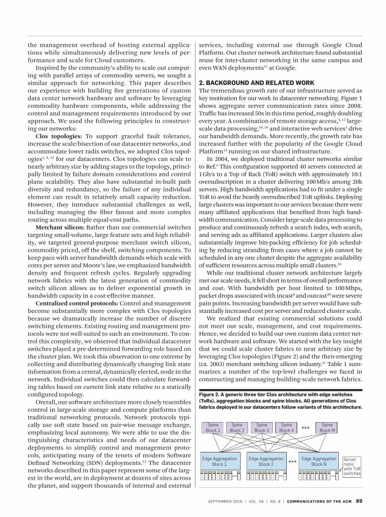
We realized that existing commercial solutions could not meet our scale, management, and cost requirements. Hence, we decided to build our own custom data center net-work hardware and software. We started with the key insight that we could scale cluster fabrics to near arbitrary size by leveraging Clos topologies (Figure 2) and the then-emerging (ca. 2003) merchant switching silicon industry.11 Table 1 sum-marizes a number of the top-level challenges we faced in constructing and managing building-scale network fabrics.
SpineBlock 1
Edge AggregationBlock 1
Edge AggregationBlock 2
Edge AggregationBlock N
Serverrackswith ToRswitches
SpineBlock 2
SpineBlock 3
SpineBlock 4
SpineBlock M
Figure 2. A generic three tier Clos architecture with edge switches (ToRs), aggregation blocks and spine blocks. All generations of Clos fabrics deployed in our datacenters follow variants of this architecture.
research highlights
90 COMMUNICATIONS OF THE ACM | SEPTEMBER 2016 | VOL. 59 | NO. 9
The following sections explain these challenges and the ratio-nale for our approach in detail.
Our topological approach, reliance on merchant sili-con, and load balancing across multipath are substantially similar to contemporaneous research.1, 15 Our centralized control protocols running on switch embedded processors are also related to subsequent substantial efforts in SDN.12 Based on our experience in the datacenter, we later applied SDN to our Wide Area Network.17 For the WAN, more CPU intensive traffic engineering and BGP routing protocols led us to move control protocols onto external servers with more powerful CPUs.
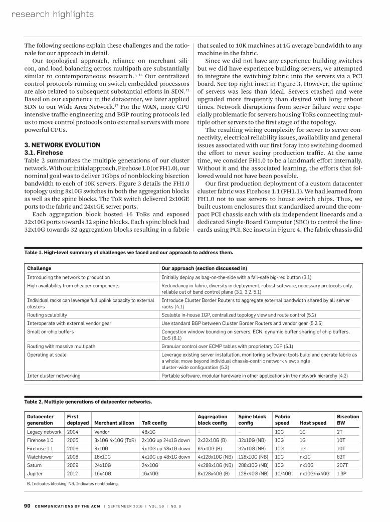
3. NETWORK EVOLUTION3.1. FirehoseTable 2 summarizes the multiple generations of our cluster network. With our initial approach, Firehose 1.0 (or FH1.0), our nominal goal was to deliver 1Gbps of nonblocking bisection bandwidth to each of 10K servers. Figure 3 details the FH1.0 topology using 8x10G switches in both the aggregation blocks as well as the spine blocks. The ToR switch delivered 2x10GE ports to the fabric and 24x1GE server ports.
Each aggregation block hosted 16 ToRs and exposed 32x10G ports towards 32 spine blocks. Each spine block had 32x10G towards 32 aggregation blocks resulting in a fabric
that scaled to 10K machines at 1G average bandwidth to any machine in the fabric.
Since we did not have any experience building switches but we did have experience building servers, we attempted to integrate the switching fabric into the servers via a PCI board. See top right inset in Figure 3. However, the uptime of servers was less than ideal. Servers crashed and were upgraded more frequently than desired with long reboot times. Network disruptions from server failure were espe-cially problematic for servers housing ToRs connecting mul-tiple other servers to the first stage of the topology.
The resulting wiring complexity for server to server con-nectivity, electrical reliability issues, availability and general issues associated with our first foray into switching doomed the effort to never seeing production traffic. At the same time, we consider FH1.0 to be a landmark effort internally. Without it and the associated learning, the efforts that fol-lowed would not have been possible.
Our first production deployment of a custom datacenter cluster fabric was Firehose 1.1 (FH1.1). We had learned from FH1.0 not to use servers to house switch chips. Thus, we built custom enclosures that standardized around the com-pact PCI chassis each with six independent linecards and a dedicated Single-Board Computer (SBC) to control the line-cards using PCI. See insets in Figure 4. The fabric chassis did
Table 2. Multiple generations of datacenter networks.
Datacenter generation
First deployed Merchant silicon ToR config
Aggregation block config
Spine block config
Fabric speed Host speed
Bisection BW
Legacy network 2004 Vendor 48x1G – – 10G 1G 2T
Firehose 1.0 2005 8x10G 4x10G (ToR) 2x10G up 24x1G down 2x32x10G (B) 32x10G (NB) 10G 1G 10T
Firehose 1.1 2006 8x10G 4x10G up 48x1G down 64x10G (B) 32x10G (NB) 10G 1G 10T
Watchtower 2008 16x10G 4x10G up 48x1G down 4x128x10G (NB) 128x10G (NB) 10G nx1G 82T
Saturn 2009 24x10G 24x10G 4x288x10G (NB) 288x10G (NB) 10G nx10G 207T
Jupiter 2012 16x40G 16x40G 8x128x40G (B) 128x40G (NB) 10/40G nx10G/nx40G 1.3P
B, Indicates blocking; NB, Indicates nonblocking.
Table 1. High-level summary of challenges we faced and our approach to address them.
Challenge Our approach (section discussed in)
Introducing the network to production Initially deploy as bag-on-the-side with a fail-safe big-red button (3.1)
High availability from cheaper components Redundancy in fabric, diversity in deployment, robust software, necessary protocols only, reliable out of band control plane (3.1, 3.2, 5.1)
Individual racks can leverage full uplink capacity to external clusters
Introduce Cluster Border Routers to aggregate external bandwidth shared by all server racks (4.1)
Routing scalability Scalable in-house IGP, centralized topology view and route control (5.2)
Interoperate with external vendor gear Use standard BGP between Cluster Border Routers and vendor gear (5.2.5)
Small on-chip buffers Congestion window bounding on servers, ECN, dynamic buffer sharing of chip buffers, QoS (6.1)
Routing with massive multipath Granular control over ECMP tables with proprietary IGP (5.1)
Operating at scale Leverage existing server installation, monitoring software; tools build and operate fabric as a whole; move beyond individual chassis-centric network view; single cluster-wide configuration (5.3)
Inter cluster networking Portable software, modular hardware in other applications in the network hierarchy (4.2)
SEPTEMBER 2016 | VOL. 59 | NO. 9 | COMMUNICATIONS OF THE ACM 91
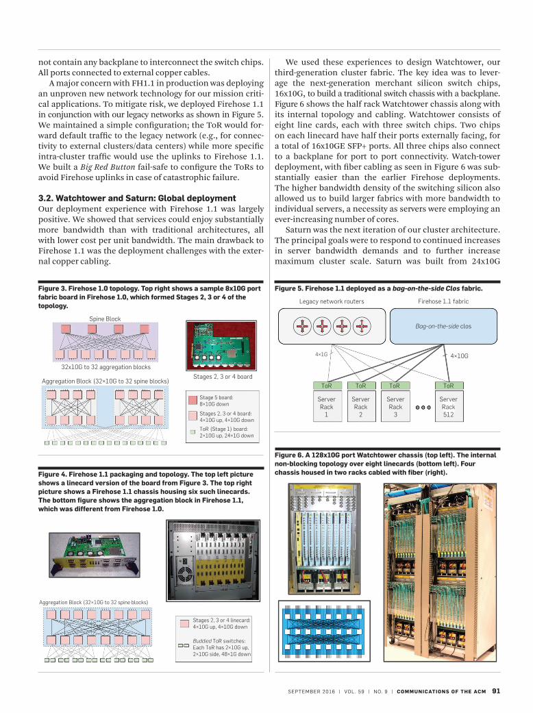
We used these experiences to design Watchtower, our third-generation cluster fabric. The key idea was to lever-age the next-generation merchant silicon switch chips, 16x10G, to build a traditional switch chassis with a backplane. Figure 6 shows the half rack Watchtower chassis along with its internal topology and cabling. Watchtower consists of eight line cards, each with three switch chips. Two chips on each linecard have half their ports externally facing, for a total of 16x10GE SFP+ ports. All three chips also connect to a backplane for port to port connectivity. Watch-tower deployment, with fiber cabling as seen in Figure 6 was sub-stantially easier than the earlier Firehose deployments. The higher bandwidth density of the switching silicon also allowed us to build larger fabrics with more bandwidth to individual servers, a necessity as servers were employing an ever-increasing number of cores.
Saturn was the next iteration of our cluster architecture. The principal goals were to respond to continued increases in server bandwidth demands and to further increase maximum cluster scale. Saturn was built from 24x10G
not contain any backplane to interconnect the switch chips. All ports connected to external copper cables.
A major concern with FH1.1 in production was deploying an unproven new network technology for our mission criti-cal applications. To mitigate risk, we deployed Firehose 1.1 in conjunction with our legacy networks as shown in Figure 5. We maintained a simple configuration; the ToR would for-ward default traffic to the legacy network (e.g., for connec-tivity to external clusters/data centers) while more specific intra- cluster traffic would use the uplinks to Firehose 1.1. We built a Big Red Button fail-safe to configure the ToRs to avoid Firehose uplinks in case of catastrophic failure.
3.2. Watchtower and Saturn: Global deploymentOur deployment experience with Firehose 1.1 was largely positive. We showed that services could enjoy substantially more bandwidth than with traditional architectures, all with lower cost per unit bandwidth. The main drawback to Firehose 1.1 was the deployment challenges with the exter-nal copper cabling.
Aggregation Block (32×10G to 32 spine blocks)
Stages 2, 3 or 4 linecard:4×10G up, 4×10G down
Buddied ToR switches:Each ToR has 2×10G up,2×10G side, 48×1G down
Figure 4. Firehose 1.1 packaging and topology. The top left picture shows a linecard version of the board from Figure 3. The top right picture shows a Firehose 1.1 chassis housing six such linecards. The bottom figure shows the aggregation block in Firehose 1.1, which was different from Firehose 1.0.
Legacy network routers
4×1G
ToR
ServerRack
1
ServerRack
2
ServerRack
3
ServerRack512
ToR ToR ToR
4×10G
Firehose 1.1 fabric
Bag-on-the-side clos
Figure 5. Firehose 1.1 deployed as a bag-on-the-side Clos fabric.
Spine Block
32x10G to 32 aggregation blocks
Aggregation Block (32×10G to 32 spine blocks)Stages 2, 3 or 4 board
Stage 5 board:8×10G down
ToR (Stage 1) board:2×10G up, 24×1G down
Stages 2, 3 or 4 board:4×10G up, 4×10G down
Figure 3. Firehose 1.0 topology. Top right shows a sample 8x10G port fabric board in Firehose 1.0, which formed Stages 2, 3 or 4 of the topology.
Figure 6. A 128x10G port Watchtower chassis (top left). The internal non-blocking topology over eight linecards (bottom left). Four chassis housed in two racks cabled with fiber (right).
research highlights
92 COMMUNICATIONS OF THE ACM | SEPTEMBER 2016 | VOL. 59 | NO. 9
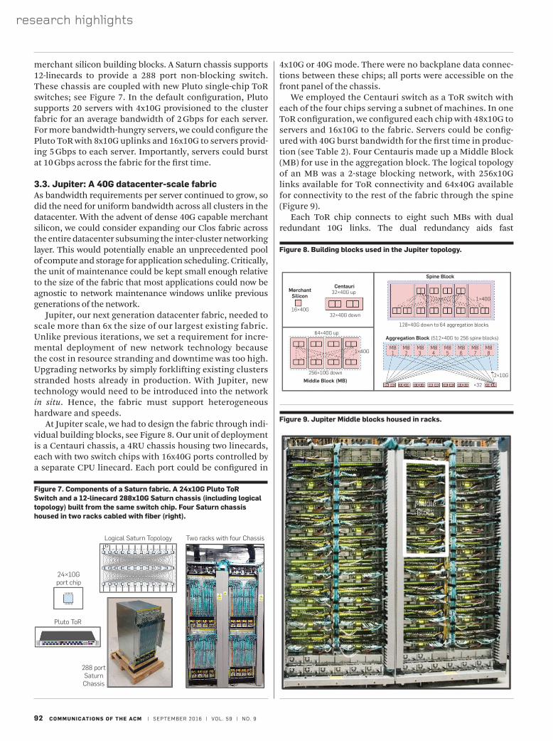
4x10G or 40G mode. There were no backplane data connec-tions between these chips; all ports were accessible on the front panel of the chassis.
We employed the Centauri switch as a ToR switch with each of the four chips serving a subnet of machines. In one ToR configuration, we configured each chip with 48x10G to servers and 16x10G to the fabric. Servers could be config-ured with 40G burst bandwidth for the first time in produc-tion (see Table 2). Four Centauris made up a Middle Block (MB) for use in the aggregation block. The logical topology of an MB was a 2-stage blocking network, with 256x10G links available for ToR connectivity and 64x40G available for connectivity to the rest of the fabric through the spine (Figure 9).
Each ToR chip connects to eight such MBs with dual redundant 10G links. The dual redundancy aids fast
merchant silicon building blocks. A Saturn chassis supports 12-linecards to provide a 288 port non-blocking switch. These chassis are coupled with new Pluto single-chip ToR switches; see Figure 7. In the default configuration, Pluto supports 20 servers with 4x10G provisioned to the cluster fabric for an average bandwidth of 2 Gbps for each server. For more bandwidth-hungry servers, we could configure the Pluto ToR with 8x10G uplinks and 16x10G to servers provid-ing 5 Gbps to each server. Importantly, servers could burst at 10 Gbps across the fabric for the first time.
3.3. Jupiter: A 40G datacenter-scale fabricAs bandwidth requirements per server continued to grow, so did the need for uniform bandwidth across all clusters in the datacenter. With the advent of dense 40G capable merchant silicon, we could consider expanding our Clos fabric across the entire datacenter subsuming the inter-cluster networking layer. This would potentially enable an unprecedented pool of compute and storage for application scheduling. Critically, the unit of maintenance could be kept small enough relative to the size of the fabric that most applications could now be agnostic to network maintenance windows unlike previous generations of the network.
Jupiter, our next generation datacenter fabric, needed to scale more than 6x the size of our largest existing fabric. Unlike previous iterations, we set a requirement for incre-mental deployment of new network technology because the cost in resource stranding and downtime was too high. Upgrading networks by simply forklifting existing clusters stranded hosts already in production. With Jupiter, new technology would need to be introduced into the network in situ. Hence, the fabric must support heterogeneous hardware and speeds.
At Jupiter scale, we had to design the fabric through indi-vidual building blocks, see Figure 8. Our unit of deployment is a Centauri chassis, a 4RU chassis housing two linecards, each with two switch chips with 16x40G ports controlled by a separate CPU linecard. Each port could be configured in
Logical Saturn Topology Two racks with four Chassis
24×10Gport chip
Pluto ToR
288 portSaturnChassis
Figure 7. Components of a Saturn fabric. A 24x10G Pluto ToR Switch and a 12-linecard 288x10G Saturn chassis (including logical topology) built from the same switch chip. Four Saturn chassis housed in two racks cabled with fiber (right).
MerchantSilicon
Centauri32×40G up
Spine Block
32×40G down
128×40G down to 64 aggregation blocks
16×40G
64×40G up
1×40GMB1 2 3 4 5 6 7 8
2×10G
1×40G
×32
MB MB MB MB MB MB MB
256×10G down
Aggregation Block (512×40G to 256 spine blocks)
Middle Block (MB)
Figure 8. Building blocks used in the Jupiter topology.
MiddleBlock
Figure 9. Jupiter Middle blocks housed in racks.
SEPTEMBER 2016 | VOL. 59 | NO. 9 | COMMUNICATIONS OF THE ACM 93
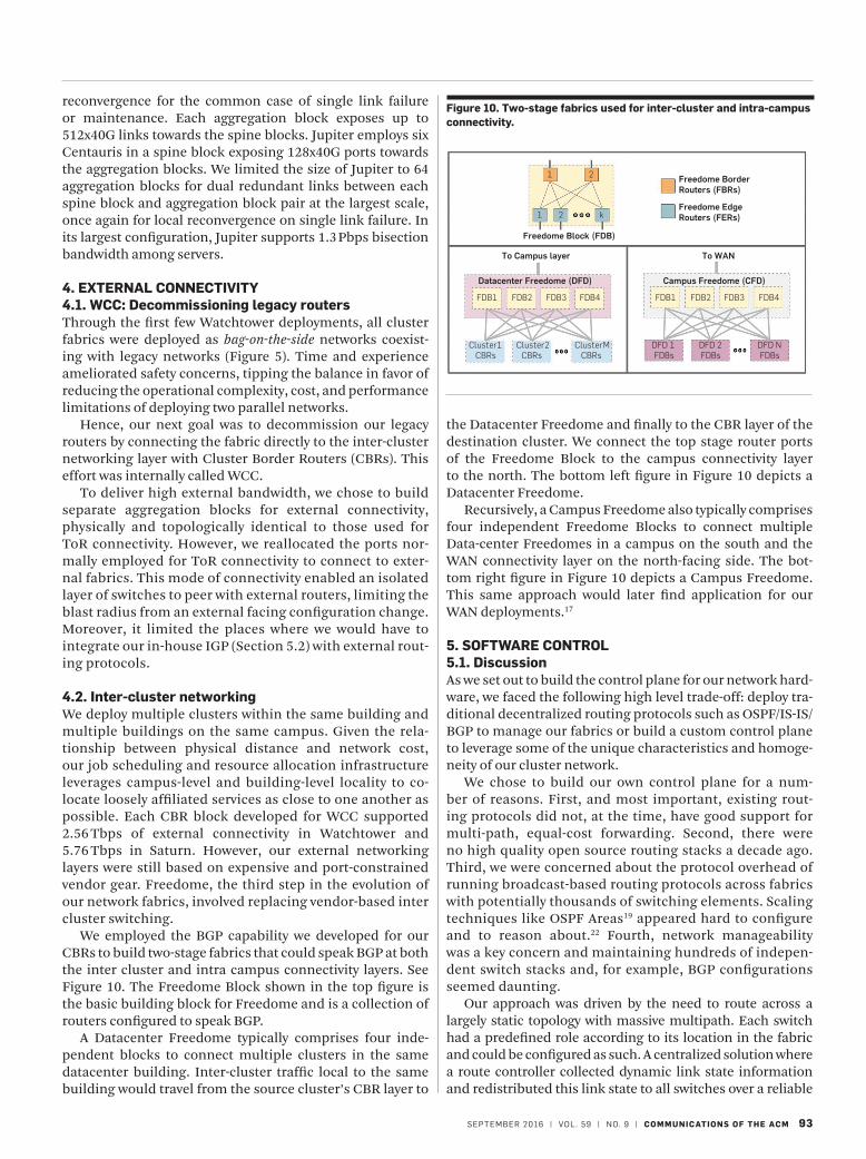
the Datacenter Freedome and finally to the CBR layer of the destination cluster. We connect the top stage router ports of the Freedome Block to the campus connectivity layer to the north. The bottom left figure in Figure 10 depicts a Datacenter Freedome.
Recursively, a Campus Freedome also typically comprises four independent Freedome Blocks to connect multiple Data-center Freedomes in a campus on the south and the WAN connectivity layer on the north-facing side. The bot-tom right figure in Figure 10 depicts a Campus Freedome. This same approach would later find application for our WAN deployments.17
5. SOFTWARE CONTROL5.1. DiscussionAs we set out to build the control plane for our network hard-ware, we faced the following high level trade-off: deploy tra-ditional decentralized routing protocols such as OSPF/IS-IS/BGP to manage our fabrics or build a custom control plane to leverage some of the unique characteristics and homoge-neity of our cluster network.
We chose to build our own control plane for a num-ber of reasons. First, and most important, existing rout-ing protocols did not, at the time, have good support for multi-path, equal-cost forwarding. Second, there were no high quality open source routing stacks a decade ago. Third, we were concerned about the protocol overhead of running broadcast-based routing protocols across fabrics with potentially thousands of switching elements. Scaling techniques like OSPF Areas19 appeared hard to configure and to reason about.22 Fourth, network manageability was a key concern and maintaining hundreds of indepen-dent switch stacks and, for example, BGP configurations seemed daunting.
Our approach was driven by the need to route across a largely static topology with massive multipath. Each switch had a predefined role according to its location in the fabric and could be configured as such. A centralized solution where a route controller collected dynamic link state information and redistributed this link state to all switches over a reliable
FDB1
Cluster1 Cluster2 ClusterMCBRs CBRs CBRs FDBs FDBs FDBs
DFD 1 DFD 2 DFD N
FDB2 FDB2FDB3 FDB3
Datacenter Freedome (DFD)
To Campus layer
Freedome Block (FDB)
Freedome BorderRouters (FBRs)
Freedome EdgeRouters (FERs)
Campus Freedome (CFD)
To WAN
FDB4 FDB4FDB1
1
1
2
2 k
Figure 10. Two-stage fabrics used for inter-cluster and intra-campus connectivity.
reconvergence for the common case of single link failure or maintenance. Each aggregation block exposes up to 512x40G links towards the spine blocks. Jupiter employs six Centauris in a spine block exposing 128x40G ports towards the aggregation blocks. We limited the size of Jupiter to 64 aggregation blocks for dual redundant links between each spine block and aggregation block pair at the largest scale, once again for local reconvergence on single link failure. In its largest configuration, Jupiter supports 1.3 Pbps bisection bandwidth among servers.
4. EXTERNAL CONNECTIVITY4.1. WCC: Decommissioning legacy routersThrough the first few Watchtower deployments, all cluster fabrics were deployed as bag-on-the-side networks coexist-ing with legacy networks (Figure 5). Time and experience ameliorated safety concerns, tipping the balance in favor of reducing the operational complexity, cost, and performance limitations of deploying two parallel networks.
Hence, our next goal was to decommission our legacy routers by connecting the fabric directly to the inter-cluster networking layer with Cluster Border Routers (CBRs). This effort was internally called WCC.
To deliver high external bandwidth, we chose to build separate aggregation blocks for external connectivity, physically and topologically identical to those used for ToR connectivity. However, we reallocated the ports nor-mally employed for ToR connectivity to connect to exter-nal fabrics. This mode of connectivity enabled an isolated layer of switches to peer with external routers, limiting the blast radius from an external facing configuration change. Moreover, it limited the places where we would have to integrate our in-house IGP (Section 5.2) with external rout-ing protocols.
4.2. Inter-cluster networkingWe deploy multiple clusters within the same building and multiple buildings on the same campus. Given the rela-tionship between physical distance and network cost, our job scheduling and resource allocation infrastructure leverages campus-level and building-level locality to co-locate loosely affiliated services as close to one another as possible. Each CBR block developed for WCC supported 2.56 Tbps of external connectivity in Watchtower and 5.76 Tbps in Saturn. However, our external networking layers were still based on expensive and port-constrained vendor gear. Freedome, the third step in the evolution of our network fabrics, involved replacing vendor-based inter cluster switching.
We employed the BGP capability we developed for our CBRs to build two-stage fabrics that could speak BGP at both the inter cluster and intra campus connectivity layers. See Figure 10. The Freedome Block shown in the top figure is the basic building block for Freedome and is a collection of routers configured to speak BGP.
A Datacenter Freedome typically comprises four inde-pendent blocks to connect multiple clusters in the same datacenter building. Inter-cluster traffic local to the same building would travel from the source cluster’s CBR layer to
research highlights
94 COMMUNICATIONS OF THE ACM | SEPTEMBER 2016 | VOL. 59 | NO. 9
out-of-band Control Plane Network (CPN) appeared to be substantially simpler and more efficient from a computation and communication perspective. The switches could then calculate forwarding tables based on current link state as del-tas relative to the underlying, known static topology that was pushed to all switches.
Overall, we treated the datacenter network as a single fabric with tens of thousands of ports rather than a col-lection of hundreds of autonomous switches that had to dynamically discover information about the fabric. We were, at this time, inspired by the success of large-scale dis-tributed storage systems with a centralized manager.13 Our design informed the control architecture for both Jupiter datacenter networks and Google’s B4 WAN,17 both of which are based on OpenFlow18 and custom SDN control stacks.
5.2. RoutingWe now present the key components of Firepath, our routing architecture for Firehose, Watchtower, and Saturn fabrics. A number of these components anticipate some of the prin-ciples of modern SDN, especially in using logically central-ized state and control. First, all switches are configured with the baseline or intended topology. The switches learn actual configuration and link state through pair-wise neighbor discovery. Next, routing proceeds with each switch exchang-ing its local view of connectivity with a centralized Firepath master, which redistributes global link state to all switches. Switches locally calculate forwarding tables based on this current view of network topology. To maintain robust-ness, we implement a Firepath master election protocol. Finally, we leverage standard BGP only for route exchange at the edge of our fabric, redistributing BGP-learned routes through Firepath.
Neighbor discovery to verify connectivity. Building a fabric with thousands of cables invariably leads to mul-tiple cabling errors. Moreover, correctly cabled links may be re-connected incorrectly after maintenance. Allow-ing traffic to use a miscabled link can lead to forwarding loops. Links that fail unidirectionally or develop high packet error rates should also be avoided and scheduled for replacement. To address these issues, we developed Neighbor Discovery (ND), an online liveness and peer cor-rectness checking protocol. ND uses the configured view of cluster topology together with a switch’s local ID to de-termine the expected peer IDs of its local ports and veri-fies that via message exchange.
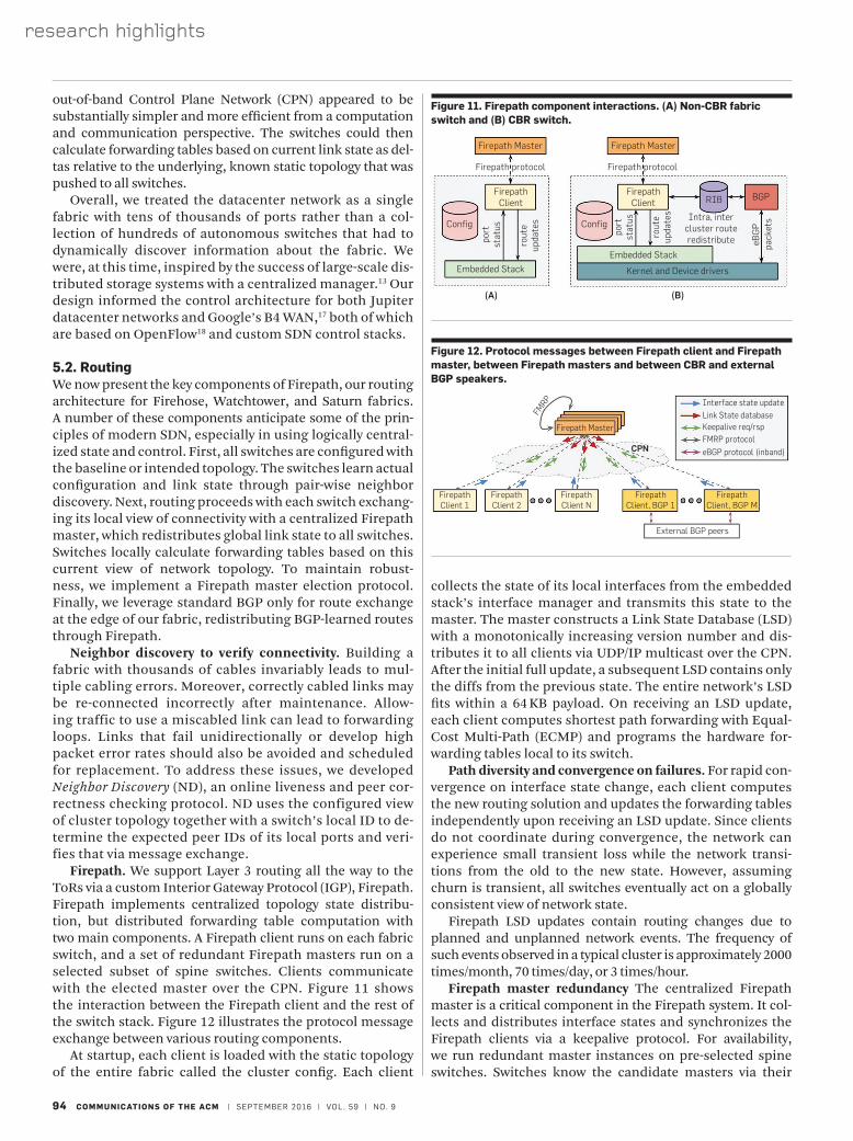
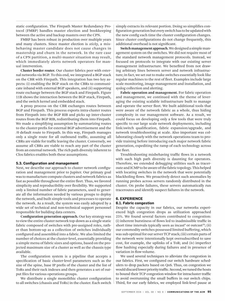
Firepath. We support Layer 3 routing all the way to the ToRs via a custom Interior Gateway Protocol (IGP), Firepath. Firepath implements centralized topology state distribu-tion, but distributed forwarding table computation with two main components. A Firepath client runs on each fabric switch, and a set of redundant Firepath masters run on a selected subset of spine switches. Clients communicate with the elected master over the CPN. Figure 11 shows the interaction between the Firepath client and the rest of the switch stack. Figure 12 illustrates the protocol message exchange between various routing components.
At startup, each client is loaded with the static topology of the entire fabric called the cluster config. Each client
collects the state of its local interfaces from the embedded stack’s interface manager and transmits this state to the master. The master constructs a Link State Database (LSD) with a monotonically increasing version number and dis-tributes it to all clients via UDP/IP multicast over the CPN. After the initial full update, a subsequent LSD contains only the diffs from the previous state. The entire network’s LSD fits within a 64 KB payload. On receiving an LSD update, each client computes shortest path forwarding with Equal-Cost Multi-Path (ECMP) and programs the hardware for-warding tables local to its switch.
Path diversity and convergence on failures. For rapid con-vergence on interface state change, each client computes the new routing solution and updates the forwarding tables independently upon receiving an LSD update. Since clients do not coordinate during convergence, the network can experience small transient loss while the network transi-tions from the old to the new state. However, assuming churn is transient, all switches eventually act on a globally consistent view of network state.
Firepath LSD updates contain routing changes due to planned and unplanned network events. The frequency of such events observed in a typical cluster is approximately 2000 times/month, 70 times/day, or 3 times/hour.
Firepath master redundancy The centralized Firepath master is a critical component in the Firepath system. It col-lects and distributes interface states and synchronizes the Firepath clients via a keepalive protocol. For availability, we run redundant master instances on pre-selected spine switches. Switches know the candidate masters via their
Firepath Master Firepath Master
Firepath protocol Firepath protocol
FirepathClient
FirepathClient
Embedded Stack
Kernel and Device drivers
Intra, intercluster routeredistribute
RIB BGP
Config Config
Embedded Stack
port
stat
us port
stat
us
rout
eup
date
s
rout
eup
date
s
eBG
Ppa
cket
s
(A) (B)
Figure 11. Firepath component interactions. (A) Non-CBR fabric switch and (B) CBR switch.
FirepathClient 1
FirepathClient 2
FirepathClient N
FirepathClient, BGP 1
Interface state updateLink State databaseKeepalive req/rspFMRP protocol
eBGP protocol (inband)
Firepath Master
FMRP
CPN
FirepathClient, BGP M
External BGP peers
Figure 12. Protocol messages between Firepath client and Firepath master, between Firepath masters and between CBR and external BGP speakers.
SEPTEMBER 2016 | VOL. 59 | NO. 9 | COMMUNICATIONS OF THE ACM 95
simply extracts its relevant portion. Doing so simplifies con-figuration generation but every switch has to be updated with the new config each time the cluster configuration changes. Since cluster configurations do not change frequently, this additional overhead is not significant.
Switch management approach. We designed a simple man-agement system on the switches. We did not require most of the standard network management protocols. Instead, we focused on protocols to integrate with our existing server management infrastructure. We benefited from not draw-ing arbitrary lines between server and network infrastruc-ture; in fact, we set out to make switches essentially look like regular machines to the rest of fleet. Examples include large scale monitoring, image management and installation, and syslog collection and alerting.
Fabric operation and management. For fabric operation and management, we continued with the theme of lever-aging the existing scalable infrastructure built to manage and operate the server fleet. We built additional tools that were aware of the network fabric as a whole, thus hiding complexity in our management software. As a result, we could focus on developing only a few tools that were truly specific to our large scale network deployments, including link/switch qualification, fabric expansion/upgrade, and network troubleshooting at scale. Also important was col-laborating closely with the network operations team to pro-vide training before introducing each major network fabric generation, expediting the ramp of each technology across the fleet.
Troubleshooting misbehaving traffic flows in a network with such high path diversity is daunting for operators. Therefore, we extended debugging utilities such as tracer-oute and ICMP to be aware of the fabric topology. This helped with locating switches in the network that were potentially blackholing flows. We proactively detect such anomalies by running probes across servers randomly distributed in the cluster. On probe failures, these servers automatically run traceroutes and identify suspect failures in the network.
6. EXPERIENCE6.1. Fabric congestionDespite the capacity in our fabrics, our networks experi-enced high congestion drops as utilization approached 25%. We found several factors contributed to congestion: (i) inherent burstiness of flows led to inadmissible traffic in short time intervals typically seen as incast8 or outcast20; (ii) our commodity switches possessed limited buffering, which was sub optimal for our server TCP stack; (iii) certain parts of the network were intentionally kept oversubscribed to save cost, for example, the uplinks of a ToR; and (iv) imperfect flow hashing especially during failures and in presence of variation in flow volume.
We used several techniques to alleviate the congestion in our fabrics. First, we configured our switch hardware sched-ulers to drop packets based on QoS. Thus, on congestion we would discard lower priority traffic. Second, we tuned the hosts to bound their TCP congestion window for intracluster traffic to avoid overrunning the small buffers in our switch chips. Third, for our early fabrics, we employed link-level pause at
static configuration. The Firepath Master Redundancy Pro-tocol (FMRP) handles master election and bookkeeping between the active and backup masters over the CPN.
FMRP has been robust in production over multiple years and many clusters. Since master election is sticky, a mis-behaving master candidate does not cause changes in mastership and churn in the network. In the rare case of a CPN partition, a multi-master situation may result, which immediately alerts network operators for man-ual intervention.
Cluster border router. Our cluster fabrics peer with exter-nal networks via BGP. To this end, we integrated a BGP stack on the CBR with Firepath. This integration has two key as-pects: (i) enabling the BGP stack on the CBRs to communi-cate inband with external BGP speakers, and (ii) supporting route exchange between the BGP stack and Firepath. Figure 11B shows the interaction between the BGP stack, Firepath, and the switch kernel and embedded stack.
A proxy process on the CBR exchanges routes between BGP and Firepath. This process exports intra-cluster routes from Firepath into the BGP RIB and picks up inter-cluster routes from the BGP RIB, redistributing them into Firepath. We made a simplifying assumption by summarizing routes to the cluster-prefix for external BGP advertisement and the /0 default route to Firepath. In this way, Firepath manages only a single route for all outbound traffic, assuming all CBRs are viable for traffic leaving the cluster. Conversely, we assume all CBRs are viable to reach any part of the cluster from an external network. The rich path diversity inherent to Clos fabrics enables both these assumptions.
5.3. Configuration and managementNext, we describe our approach to cluster network configu-ration and management prior to Jupiter. Our primary goal was to manufacture compute clusters and network fabrics as fast as possible throughout the entire fleet. Thus, we favored simplicity and reproducibility over flexibility. We supported only a limited number of fabric parameters, used to gener-ate all the information needed by various groups to deploy the network, and built simple tools and processes to operate the network. As a result, the system was easily adopted by a wide set of technical and non-technical support personnel responsible for building data centers.
Configuration generation approach. Our key strategy was to view the entire cluster network top-down as a single static fabric composed of switches with pre-assigned roles, rath-er than bottom-up as a collection of switches individually configured and assembled into a fabric. We also limited the number of choices at the cluster-level, essentially providing a simple menu of fabric sizes and options, based on the pro-jected maximum size of a cluster as well as the chassis type available.
The configuration system is a pipeline that accepts a specification of basic cluster-level parameters such as the size of the spine, base IP prefix of the cluster and the list of ToRs and their rack indexes and then generates a set of out-put files for various operations groups.
We distribute a single monolithic cluster configuration to all switches (chassis and ToRs) in the cluster. Each switch
research highlights
96 COMMUNICATIONS OF THE ACM | SEPTEMBER 2016 | VOL. 59 | NO. 9
the proper monitoring and alerting been in place for fabric backplane and CPN links.
Component misconfiguration. A prominent miscon-figuration outage was on a Freedome fabric. Recall that a Freedome chassis runs the same codebase as the CBR with its integrated BGP stack. A CLI interface to the CBR BGP stack supported configuration. We did not implement lock-ing to prevent simultaneous read/write access to the BGP configuration. During a planned BGP reconfiguration of a Freedome block, a separate monitoring system coinciden-tally used the same interface to read the running config while a change was underway. Unfortunately, the resulting partial configuration led to undesirable behavior between Freedome and its BGP peers.
We mitigated this error by quickly reverting to the previ-ous configuration. However, it taught us to harden our oper-ational tools further. It was not enough for tools to configure the fabric as a whole; they needed to do so in a safe, secure and consistent way.
7. CONCLUSIONThis paper presents a retrospective on ten years and five generations of production datacenter networks. We employed complementary techniques to deliver more bandwidth to larger clusters than would otherwise be possible at any cost. We built multi-stage Clos topolo-gies from bandwidth-dense but feature-limited merchant switch silicon. Existing routing protocols were not easily adapted to Clos topologies. We departed from conven-tional wisdom to build a centralized route controller that leveraged global configuration of a predefined cluster plan pushed to every datacenter switch. This centralized con-trol extended to our management infrastructure, enabling us to eschew complex protocols in favor of best practices from managing the server fleet. Our approach has enabled us to deliver substantial bisection bandwidth for building-scale fabrics, all with significant application benefit.
AcknowledgmentsMany teams contributed to the success of the datacenter network within Google. In particular, we would like to acknowledge the Platforms Networking (PlaNet) Hardware and Software Development, Platforms Software Quality Assurance (SQA), Mechanical Engineering, Cluster Engineering (CE), Network Architecture and Operations (NetOps), Global Infrastructure Group (GIG), and Site Reliability Engineering (SRE) teams, to name a few.
ToRs to keep servers from over-running oversubscribed uplinks. Fourth, we enabled Explicit Congestion Notification (ECN) on our switches and optimized the host stack response to ECN signals.2 Fifth, we monitored application bandwidth requirements in the face of oversubscription ratios and could provision bandwidth by deploying Pluto ToRs with four or eight uplinks as required. Sixth, the merchant silicon had shared memory buffers used by all ports, and we tuned the buffer sharing scheme on these chips so as to dynamically allocate a disproportionate fraction of total chip buffer space to absorb temporary traffic bursts. Finally, we carefully config-ured switch hashing functionality to support good ECMP load balancing across multiple fabric paths.
Our congestion mitigation techniques delivered sub-stantial improvements. We reduced the packet discard rate in a typical Clos fabric at 25% average utilization from 1% to < 0.01%. Further improving fabric congestion response remains an ongoing effort.
6.2. OutagesWhile the overall availability of our datacenter fabrics has been satisfactory, our outages fall into three categories repre-senting the most common failures in production: (i) control software problems at scale; (ii) aging hardware exposing pre-viously unhandled failure modes; and (iii) misconfigurations of certain components.
Control software problems at large scale. A datacenter power event once caused the entire fabric to restart simul-taneously. However, the control software did not converge without manual intervention. The instability took place because our liveness protocol (ND) and route computation contended for limited CPU resources on embedded switch CPUs. On entire fabric reboot, routing experienced huge churn, which, in turn, led ND not to respond to heartbeat messages quickly enough. This in turn led to a snowball effect for routing where link state would spuriously go from up to down and back to up again. We stabilized the network by manually bringing up a few blocks at a time.
Going forward, we included the worst case fabric reboot in our test plans. Since the largest scale datacenter could never be built in a hardware test lab, we launched efforts to stress test our control software at scale in virtualized envi-ronments. We also heavily scrutinized any timer values in liveness protocols, tuning them for the worst case while bal-ancing slower reaction time in the common case. Finally, we reduced the priority of non-critical processes that shared the same CPU.
Aging hardware exposes unhandled failure modes. Over years of deployment, our inbuilt fabric redundancy degrad-ed as a result of aging hardware. For example, our software was vulnerable to internal/backplane link failures, lead-ing to rare traffic blackholing. Another example centered around failures of the CPN. Each fabric chassis had dual redundant links to the CPN in active-standby mode. We initially did not actively monitor the health of both the ac-tive and standby links. With age, the vendor gear suffered from unidirectional failures of some CPN links exposing unhandled corner cases in our routing protocols. Both these problems would have been easier to mitigate had
References 1. Al-Fares, M., Loukissas, A., Vahdat, A.
A scalable, commodity data center network architecture. In ACM SIGCOMM Computer Communication Review. Volume 38 (2008), ACM, 63–74.
2. Alizadeh, M., Greenberg, A., Maltz, D.A., Padhye, J., Patel, P., Prabhakar, B., Sengupta, S., Sridharan, M. Data center TCP (DCTCP). ACM SIGCOMM Comput. Commun. Rev. 41, 4 (2011), 63–74.
3. Barroso, L.A., Dean, J., Holzle, U. Web search for a planet: The Google cluster architecture. Micro. IEEE 23, 2 (2003), 22–28.
4. Barroso, L.A., Hölzle, U. The datacenter as a computer: An introduction to the design of warehouse-scale machines. Syn. Lect. Comput. Architect. 4, 1 (2009), 1–108.
5. Calder, B., Wang, J., Ogus, A., Nilakantan, N., Skjolsvold, A., McKelvie, S., Xu, Y., Srivastav, S., Wu, J., Simitci, H., et al. Windows Azure storage: A highly available cloud storage service with strong consistency. In Proceedings of the Twenty-Third ACM Symposium on Operating Systems Principles (2011), ACM, 143–157.
SEPTEMBER 2016 | VOL. 59 | NO. 9 | COMMUNICATIONS OF THE ACM 97
6. Chambers, C., Raniwala, A., Perry, F., Adams, S., Henry, R.R., Bradshaw, R., Weizenbaum, N. Flumejava: Easy, efficient data-parallel pipelines. In ACM Sigplan Notices. Volume 45 (2010), ACM, 363–375.
7. Chang, F., Dean, J., Ghemawat, S., Hsieh, W.C., Wallach, D.A., Burrows, M., Chandra, T., Fikes, A., Gruber, R.E. Bigtable: A distributed storage system for structured data. ACM Trans. Comput. Syst. 26, 2 (2008), 4.
8. Chen, Y., Griffith, R., Liu, J., Katz, R.H., Joseph, A.D. Understanding TCP incast throughput collapse in datacenter networks. In Proceedings of the 1st ACM Workshop on Research on Enterprise Networking (2009), ACM, 73–82.
9. Clos, C. A study of non-blocking switching networks. Bell Syst. Tech. J. 32, 2 (1953), 406–424.
10. Dean, J., Ghemawat, S. MapReduce: Simplified data processing on large clusters. Commun. ACM 51, 1 (2008), 107–113.
11. Farrington, N., Rubow, E., Vahdat, A. Data center switch architecture in the age of merchant silicon. In Proceedings of the 17th IEEE Symposium on HOT Interconnects, 2009 (2009), 93–102.
12. Feamster, N., Rexford, J., Zegura, E. The road to SDN: An intellectual history of programmable networks. ACM Queue 11, 12 (December 2013), 87–98.
13. Ghemawat, S., Gobioff, H., Leung, S.-T. The Google file system. In ACM SIGOPS Operating Systems Review. Volume 37 (2003), ACM, 29–43.
14. Google Cloud Platform. https://cloud.google.com.
15. Greenberg, A., Hamilton, J.R., Jain, N., Kandula, S., Kim, C., Lahiri, P., Maltz, D.A., Patel, P., Sengupta, S. VL2: A scalable and flexible data center network. In Proceedings of the ACM SIGCOMM Computer Communication Review (2009), 51–62.
16. Isard, M., Budiu, M., Yu, Y., Birrell, A., Fetterly, D. Dryad: Distributed data-parallel programs from sequential building blocks. In Proceedings of the ACM SIGOPS Operating Systems Review (2007), 59–72.
17. Jain, S., Kumar, A., Mandal, S., Ong, J., Poutievski, L., Singh, A., Venkata, S., Wanderer, J., Zhou, J., Zhu, M., Zolla, J., Hölzle, U., Stuart, S., Vahdat, A. B4: Experience with a globally-deployed software defined WAN. In Proceedings of the ACM SIGCOMM (2013), 3–14.
18. McKeown, N., Anderson, T., Balakrishnan, H., Parulkar, G., Peterson, L., Rexford, J., Shenker, S., Turner, J. Openflow: Enabling innovation in campus networks. ACM SIGCOMM Comput. Commun. Rev. 38, 2 (2008), 69–74.
19. Moy, J. OSPF version 2. STD 54, RFC Editor, April 1998. http://www.rfc-editor.org/rfc/rfc2328.txt.
20. Prakash, P., Dixit, A.A., Hu, Y.C., Kompella, R.R. The TCP outcast problem: Exposing unfairness in data center networks. In Proceedings of the NSDI (2012), 413–426.
21. Singh, A., Ong, J., Agarwal, A., Anderson, G., Armistead, A., Bannon, R., Boving, S., Desai, G., Felderman, B., Germano, P., Kanagala, A., Provost, J., Simmons, J., Tanda, E., Wanderer, J., Hölzle, U., Stuart, S., Vahdat,
Copyright held by authors/owners.
Arjun Singh, Joon Ong, Amit Agarwal, Glen Anderson, Ashby Armistead, Roy Bannon, Seb Boving, Gaurav Desai, Bob Felderman, Paulie Germano, Anand
Kanagala, Jeff Provost, Jason Simmons, Eiichi Tanda, Jim Wanderer, Urs Hölzle, Stephen Stuart, and Amin Vahdat ([email protected]) Google, Inc.
A. Jupiter rising: A decade of clos topologies and centralized control in Google’s datacenter network. In Proceedings of the 2015 ACM Conference on Special Interest Group on Data Communication (2015), ACM, 183–197.
22. Thorup, M. OSPF areas considered harmful. IETF Internet Draft 00, individual, April 2003. http://tools.ietf.org/html/draft-thorup-ospf-harmful-00.
23. Vahdat, A., Al-Fares, M., Farrington, N.,
Mysore, R.N., Porter, G., Radhakrishnan, S. Scale-out networking in the data center. IEEE MICRO 30, 4 (August 2010), 29–41.
24. Verma, A., Pedrosa, L., Korupolu, M., Oppenheimer, D., Tune, E., Wilkes, J. Large-scale cluster management at Google with Borg. In Proceedings of the Tenth European Conference on Computer Systems (2015), ACM, 18.
ACM Transactions on Parallel ComputingSolutions to Complex Issues in ParallelismEditor-in-Chief: Phillip B. Gibbons, Intel Labs, Pittsburgh, USA
For further information or to submit your manuscript, visit topc.acm.org
Subscribe at www.acm.org/subscribe
ACM Transactions on Parallel Computing (TOPC) is a forum for novel and innovative work on all aspects of parallel computing, including foundational and theoretical aspects, systems, languages, architectures, tools, and applications. It will address all classes of parallel-processing platforms including concurrent, multithreaded, multicore, accelerated, multiprocessor, clusters, and supercomputers.
Subject Areas
• Parallel Programming Languages and Models• Parallel System Software• Parallel Architectures• Parallel Algorithms and Theory• Parallel Applications• Tools for Parallel Computing
For further information or to submit your manuscript, visit topc.acm.org
Subscribe at www.acm.org/subscribe