Embed Size (px)
Citation preview
3100LR12D
User Manual
Issue 2.1 June 2005
3100LR12D PRODUCT USER MANUAL
OmniSTAR a Fugro Group CompanyIssue 2.0 03/03 3100LR12D User Manual
ii
Notice to Customers
This manual has been produced to ensure the very best performance from your OmniSTAR receiver. The manual has been clearly set out with simple instructions to ensure hassle free usage of your OmniSTAR receiver. This publication could contain technical inaccuracies or typographical errors. Changes are periodically made to the information herein; these changes will be incorporated in new editions of the manual. Should you require further assistance please contact your local dealer or the OmniSTAR office.
OmniSTAR Customer Support and 24 Hour Help Line OmniSTAR BV Dillenburgsingel 69 2263 HW Leidschendam P.O. box 113 2260 AC Leidschendam Contact Numbers Office: +31 70 3170900 Technical Support: +31 70 3170913 Fax Number Office: +31 70 3170919
World Wide Web Internet Address: www.omnistar.nlEmail address: [email protected]

3100LR12D PRODUCT USER MANUAL
OmniSTAR a Fugro Group CompanyIssue 2.0 03/03 3100LR12D User Manual
iii
Dealer Information
Name _____________________________
Address _____________________________
City _____________________________
State _____________________________
Post Code _____________________________
Country _____________________________
Phone _____________________________
Fax _____________________________
Email _____________________________
3100LR12D PRODUCT USER MANUAL
OmniSTAR a Fugro Group CompanyIssue 2.0 03/03 3100LR12D User Manual
iv
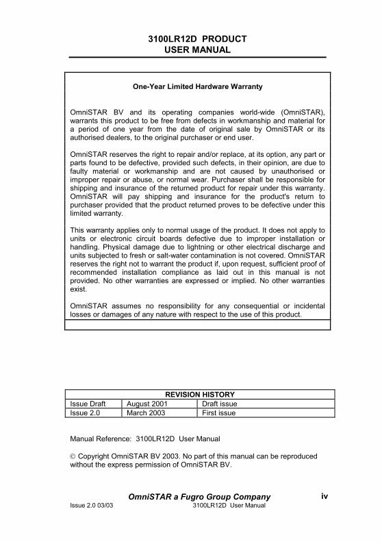
One-Year Limited Hardware Warranty
OmniSTAR BV and its operating companies world-wide (OmniSTAR), warrants this product to be free from defects in workmanship and material for a period of one year from the date of original sale by OmniSTAR or its authorised dealers, to the original purchaser or end user.
OmniSTAR reserves the right to repair and/or replace, at its option, any part or parts found to be defective, provided such defects, in their opinion, are due to faulty material or workmanship and are not caused by unauthorised or improper repair or abuse, or normal wear. Purchaser shall be responsible for shipping and insurance of the returned product for repair under this warranty. OmniSTAR will pay shipping and insurance for the product's return to purchaser provided that the product returned proves to be defective under this limited warranty.
This warranty applies only to normal usage of the product. It does not apply to units or electronic circuit boards defective due to improper installation or handling. Physical damage due to lightning or other electrical discharge and units subjected to fresh or salt-water contamination is not covered. OmniSTAR reserves the right not to warrant the product if, upon request, sufficient proof of recommended installation compliance as laid out in this manual is not provided. No other warranties are expressed or implied. No other warranties exist.
OmniSTAR assumes no responsibility for any consequential or incidental losses or damages of any nature with respect to the use of this product.
REVISION HISTORY Issue Draft August 2001 Draft issue Issue 2.0 March 2003 First issue
Manual Reference: 3100LR12D User Manual Copyright OmniSTAR BV 2003. No part of this manual can be reproduced without the express permission of OmniSTAR BV.
3100LR12D PRODUCT USER MANUAL
OmniSTAR a Fugro Group CompanyIssue 2.0 03/03 3100LR12D User Manual
v
TABLE OF CONTENTS
TABLE OF CONTENTS ................................................................................V
LIST OF FIGURES......................................................................................VII
LIST OF TABLES .......................................................................................VII
INTRODUCTION........................................................................................... 1
GPS/DGPS INTRODUCTION ....................................................................... 2
THE OMNISTAR SYSTEM ............................................................................. 3 SUBSCRIPTION TYPE .................................................................................... 3
THE 3100LR12D........................................................................................... 4
GENERAL DESCRIPTION ............................................................................... 4 OPTIONS..................................................................................................... 5
OPERATING CONSIDERATIONS ................................................................ 6
NUMBER OF VISIBLE SATELLITES ................................................................... 6 MULTIPATH.................................................................................................. 6 POSITION DILUTION OF PRECISION (PDOP)................................................... 7 SATELLITE ELEVATIONS ................................................................................ 7 DIFFERENTIAL CORRECTIONS........................................................................ 8
QUICK START.............................................................................................. 9
RECEIVER INTERFACES .......................................................................... 12
POWER..................................................................................................... 12 ANTENNA .................................................................................................. 13 DATA ........................................................................................................ 13 COMMAND................................................................................................. 14 UTILITY ..................................................................................................... 14 AUXILIARY................................................................................................. 15
INSTALLATION .......................................................................................... 16
INSTALLATION CONSIDERATIONS................................................................. 16 ELECTRICAL GROUNDING REQUIREMENTS ................................................... 16 COUNTER ELECTROMAGNETIC FORCE (CEMF)............................................ 17 CABLE INSTALLATION ................................................................................. 18 ANTENNA LOCATION .................................................................................. 19
MENUS AND DISPLAYS ............................................................................ 20
3100LR12D PRODUCT USER MANUAL
OmniSTAR a Fugro Group CompanyIssue 2.0 03/03 3100LR12D User Manual
vi
POWER ON MENU...................................................................................... 22 CURRENT READINGS MENU ........................................................................ 23 USER SETTINGS MENU............................................................................... 24 ABOUT MENU ............................................................................................ 26 3100LR12D VBS SERVICES MENU............................................................ 27 3100LR12D VIRTUAL BASE STATION (VBS) CONTROL MENU ...................... 29 MAINTENANCE MENU ................................................................................. 30 RECEIVER SUBSCRIPTION STATUS MENU .................................................... 31 REMOTE SITES MENU FOR DGPS SERVICE................................................. 32 CHANNEL SELECTION MENU ....................................................................... 33 AUTOSCAN MENU ...................................................................................... 34
RECEIVER SERVICE PROCEDURE.......................................................... 35
TECHNICAL SPECIFICATIONS ................................................................. 36
ACRONYMS USED IN THIS MANUAL ....................................................... 37
APPENDIX A .............................................................................................. 38
NMEA 0183 INTRODUCTION ...................................................................... 38 NMEA 0183 MESSAGE FORMAT ................................................................ 39 NMEA 0183 MESSAGE OPTIONS................................................................ 40 NMEA 0183 MESSAGE FORMATS............................................................... 41
APPENDIX B .............................................................................................. 51
LIST OF COMMUNICATION SATELLITES .......................................................... 51
APPENDIX C .............................................................................................. 52
LIST OF REFERENCE STATIONS.................................................................... 52
APPENDIX D ............................................................................................. 56
OMNISTAR RECEIVER PROBLEM REPORT FORM ......................................... 56
APPENDIX E .............................................................................................. 57
OMNISTAR SUBSCRIPTION AGREEMENT FORM............................................. 57
3100LR12D PRODUCT USER MANUAL
OmniSTAR a Fugro Group CompanyIssue 2.0 03/03 3100LR12D User Manual
vii
List of Figures Figure 1: 3100LR12D with DGPS Antenna.....................................................5 Figure 2: Multipath...........................................................................................7 Figure 3: 3100LR12D Rear Panel...................................................................9 Figure 4: 3100LR12D Front Panel ................................................................10 Figure 5: World coverage map for the OmniSTAR service ............................11 Figure 6: EA-SAT global beam for coverage in Europe and the Middle East. 11 Figure 7: Zener Diode Connected..................................................................17 Figure 8: Reference stations and coverage area per satellite ........................51
List of Tables Table 1: Data Port Pin Assignment - (* no connection by default) .................13 Table 2: Data Cable Pin Assignment.............................................................13 Table 3: Command Port Pin Assignment.......................................................14 Table 4: Utility Port Pin Assignment ..............................................................14 Table 5: Auxiliary Port Pin Assignment - (* no connection by default)............15 Table 6: NMEA 0183 messages available for the 3100LR12D ......................40 Table 7: Description of the ALM message. ....................................................41 Table 8: Description of the GBS message.....................................................42 Table 9: Description of the GGA message. ...................................................43 Table 10: Description of the GLL message....................................................44 Table 11: Description of the GRS message...................................................44 Table 12: Description of the GSA message...................................................45 Table 13: Description of the GST message. ..................................................46 Table 14: Description of the GSV message...................................................47 Table 15: Description of the RMC message. .................................................48 Table 16: Description of the VTG message. .................................................49 Table 17: Description of the ZDA message. ..................................................50 Table 18: Worldwide satellite frequencies and symbol rates .........................51 Table 19: Reference stations on EA-SAT......................................................52 Table 20: Reference stations on AF-SAT ......................................................53 Table 21: Reference stations on AP-Sat........................................................53 Table 22: Reference stations on AM-Sat .......................................................54
3100LR12D PRODUCT USER MANUAL
OmniSTAR a Fugro Group CompanyIssue 2.0 03/03 3100LR12D User Manual
1
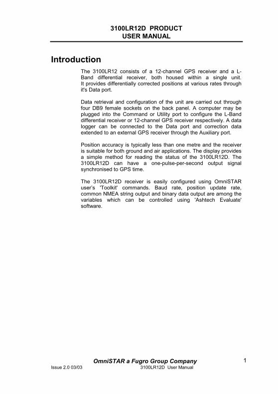
Introduction The 3100LR12 consists of a 12-channel GPS receiver and a L-Band differential receiver, both housed within a single unit. It provides differentially corrected positions at various rates through it's Data port. Data retrieval and configuration of the unit are carried out through four DB9 female sockets on the back panel. A computer may be plugged into the Command or Utility port to configure the L-Band differential receiver or 12-channel GPS receiver respectively. A data logger can be connected to the Data port and correction data extended to an external GPS receiver through the Auxiliary port. Position accuracy is typically less than one metre and the receiver is suitable for both ground and air applications. The display provides a simple method for reading the status of the 3100LR12D. The 3100LR12D can have a one-pulse-per-second output signal synchronised to GPS time. The 3100LR12D receiver is easily configured using OmniSTAR user’s 'Toolkit' commands. Baud rate, position update rate, common NMEA string output and binary data output are among the variables which can be controlled using 'Ashtech Evaluate' software.
3100LR12D PRODUCT USER MANUAL
OmniSTAR a Fugro Group CompanyIssue 2.0 03/03 3100LR12D User Manual
2
GPS/DGPS Introduction The Global Positioning System (GPS) is a reliable, continuous, all-weather navigation system, which is operated by the United States Government. At the time of writing, the space segment of GPS includes a constellation of 28 satellites, which orbit the earth at an altitude of approximately 22.000 km. These satellites (Space Vehicles or SV’s) transmit radio signals containing precise satellite time and position information. By receiving four or more of these signals a 3-dimensional position can be computed. Although GPS provides an acceptable level of performance for some users, many applications demand a more reliable and precise position than GPS alone can provide. In such cases Differential GPS (DGPS) must be used. The purpose of DGPS is to minimise the effects of atmospheric and satellite errors on the position determination. In order to achieve this a reference GPS receiver must be installed at a point of known co-ordinates. This receiver uses the radio signals from each of the GPS satellites, which are in view to measure so-called pseudo-ranges to these satellites. Because the exact locations of the satellites and the reference receiver are known, it is then possible to determine the difference between the actual and the expected pseudo-ranges (pseudo-range correction or PRC). In order to provide compatibility for exchanging this correction data, a standard has been developed by the Radio Technical Commission for Maritime Services Special Committee 104. This standard is commonly known as RTCM SC-104. When RTCM version 2.0 correction data from the reference receiver is applied to a nearby GPS receiver, the position accuracy will be substantially better than if stand-alone GPS were to be used.
3100LR12D PRODUCT USER MANUAL
OmniSTAR a Fugro Group CompanyIssue 2.0 03/03 3100LR12D User Manual
3
The OmniSTAR system
The 3100LR12D is one of several DGPS receivers which have been designed to work with the world-wide OmniSTAR service. The OmniSTAR DGPS system delivers corrections from an array of reference stations, which are located all around the world (see appendix C). The RTCM correction data from these reference stations is provided to OmniSTAR’s two Network Control Centres (NCC), where the corrections are decoded, checked, and repackaged in a highly efficient format for broadcast. The OmniSTAR data is broadcast over a series of L-band communication satellites. The signal transmitted over each of these satellites contains the corrections from the reference stations in and close to the region in which this satellite can be received. When a receiver with a valid subscription receives data through one of OmniSTAR’s satellite channels it will output a differentially corrected position. The way in which the correction data from each individual reference station will be used in the position calculation depends on the user’s OmniSTAR subscription.
Subscription type
The 3100LR12D supports the following OmniSTAR service:
Virtual Base Station (VBS), where the data from multiple reference stations is used in the processor software to produce enhanced corrections for the user's location. This service provides optimal position accuracy with a minimum dependence on the user’s location. The VBS service can be obtained on a continental, country or regional basis.
3100LR12D PRODUCT USER MANUAL
OmniSTAR a Fugro Group CompanyIssue 2.0 03/03 3100LR12D User Manual
4
The 3100LR12D
General Description The 3100LR12D is the main part of a portable system. It contains the satellite RF receiving and signal processing components. All ancillary equipment is plugged into the appropriate sockets on the receiver rear panel. A typical 3100LR12D package will consist of the following items:
• 3100LR12D (receiver)
• Data cable
• Power cable
• RF cable
• Antenna
• CD-ROM with User Toolkit software and Manual
• User manual
3100LR12D PRODUCT USER MANUAL
OmniSTAR a Fugro Group CompanyIssue 2.0 03/03 3100LR12D User Manual
5
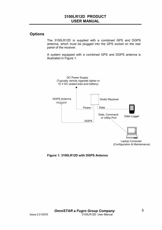
Options The 3100LR12D is supplied with a combined GPS and DGPS antenna, which must be plugged into the GPS socket on the rear panel of the receiver. A system equipped with a combined GPS and DGPS antenna is illustrated in Figure 1.
Figure 1: 3100LR12D with DGPS Antenna
Dodici Receiver
Data Logger
Laptop Computer(Configuration & Maintenance)
DGPS Antenna
DC Power Supply(Typically vehicle cigarette lighter or12 V DC sealed lead acid battery)
DataPower
DGPS
Data, Command or Utility Port
3100LR12D PRODUCT USER MANUAL
OmniSTAR a Fugro Group CompanyIssue 2.0 03/03 3100LR12D User Manual
6
Operating considerations The 3100LR12D has proven to be a high-quality positioning device. The accuracy that the user can obtain depends on several factors, including:
• Number of visible satellites • Multipath • Dilution of Precision (DOP) • Satellite elevations • Differential correction
Number of visible satellites
A minimum of four satellites is required to calculate a 3-dimensional position. In general it can be said that every increase in the number of visible satellites will result in an increase in the system’s accuracy. As the GPS satellites orbit around the earth the number of visible satellites will change in time. The GPS constellation has been designed so as to provide a minimum of 4 visible satellites at any location at all times. The number of visible satellites can decrease due to blockage by objects such as trees and buildings.
Multipath
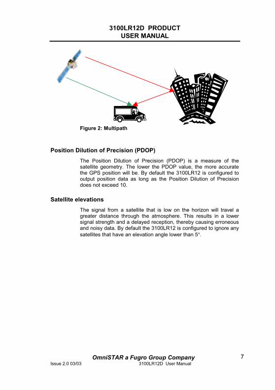
It is possible for satellite signals to reflect off large nearby objects such as buildings, cars or even the ground, thereby resulting in an erroneous distance measurement. This phenomenon is known as multipath. Multipath can cause significant errors in the position determination and it is therefore important to place the receiver in an environment, which is free of large reflective surfaces. It is also recommended to mount the receiver directly onto a surface, while maintaining a clear view of the sky in all directions.
3100LR12D PRODUCT USER MANUAL
OmniSTAR a Fugro Group CompanyIssue 2.0 03/03 3100LR12D User Manual
7
Figure 2: Multipath
Position Dilution of Precision (PDOP)
The Position Dilution of Precision (PDOP) is a measure of the satellite geometry. The lower the PDOP value, the more accurate the GPS position will be. By default the 3100LR12 is configured to output position data as long as the Position Dilution of Precision does not exceed 10.
Satellite elevations
The signal from a satellite that is low on the horizon will travel a greater distance through the atmosphere. This results in a lower signal strength and a delayed reception, thereby causing erroneous and noisy data. By default the 3100LR12 is configured to ignore any satellites that have an elevation angle lower than 5°.
3100LR12D PRODUCT USER MANUAL
OmniSTAR a Fugro Group CompanyIssue 2.0 03/03 3100LR12D User Manual
8
Differential corrections
For accurate positioning it is essential that the differential corrections are received. In order to ensure reception of the OmniSTAR satellite signal the line of sight towards the satellite must not be blocked by objects such as trees and buildings. Multipath reflections can cause destructive interference, thereby significantly decreasing the signal strength. It is therefore recommended to mount the 3100LR12D directly onto a surface in a reflection free environment. Although the 3100LR12D has been designed to provide optimal system performance under most circumstances, it is possible, due to the nature of radio communications, that the system performance degrades due to local interference sources.
3100LR12D PRODUCT USER MANUAL
OmniSTAR a Fugro Group CompanyIssue 2.0 03/03 3100LR12D User Manual
9
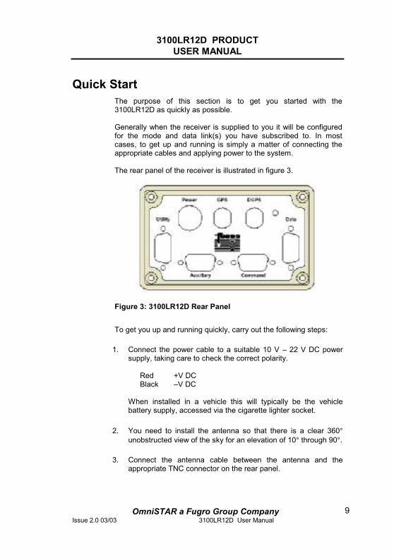
Quick Start The purpose of this section is to get you started with the 3100LR12D as quickly as possible. Generally when the receiver is supplied to you it will be configured for the mode and data link(s) you have subscribed to. In most cases, to get up and running is simply a matter of connecting the appropriate cables and applying power to the system. The rear panel of the receiver is illustrated in figure 3.
Figure 3: 3100LR12D Rear Panel
To get you up and running quickly, carry out the following steps:
1. Connect the power cable to a suitable 10 V – 22 V DC power supply, taking care to check the correct polarity.
Red +V DC Black –V DC When installed in a vehicle this will typically be the vehicle battery supply, accessed via the cigarette lighter socket.
2. You need to install the antenna so that there is a clear 360°unobstructed view of the sky for an elevation of 10° through 90°.
3. Connect the antenna cable between the antenna and the appropriate TNC connector on the rear panel.
3100LR12D PRODUCT USER MANUAL
OmniSTAR a Fugro Group CompanyIssue 2.0 03/03 3100LR12D User Manual
10
4. Ensure the DC power supply is OFF, then connect the power cable into the Power socket on the receiver back panel.
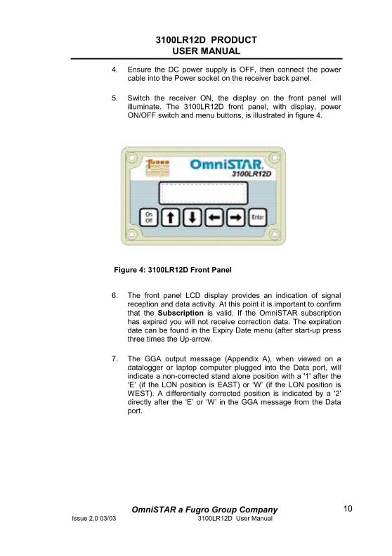
5. Switch the receiver ON, the display on the front panel will illuminate. The 3100LR12D front panel, with display, power ON/OFF switch and menu buttons, is illustrated in figure 4.
Figure 4: 3100LR12D Front Panel
6. The front panel LCD display provides an indication of signal reception and data activity. At this point it is important to confirm that the Subscription is valid. If the OmniSTAR subscription has expired you will not receive correction data. The expiration date can be found in the Expiry Date menu (after start-up press three times the Up-arrow.
7. The GGA output message (Appendix A), when viewed on a datalogger or laptop computer plugged into the Data port, will indicate a non-corrected stand alone position with a '1' after the ‘E’ (if the LON position is EAST) or ‘W’ (if the LON position is WEST). A differentially corrected position is indicated by a '2' directly after the ‘E’ or ‘W’ in the GGA message from the Data port.
3100LR12D PRODUCT USER MANUAL
OmniSTAR a Fugro Group CompanyIssue 2.0 03/03 3100LR12D User Manual
11
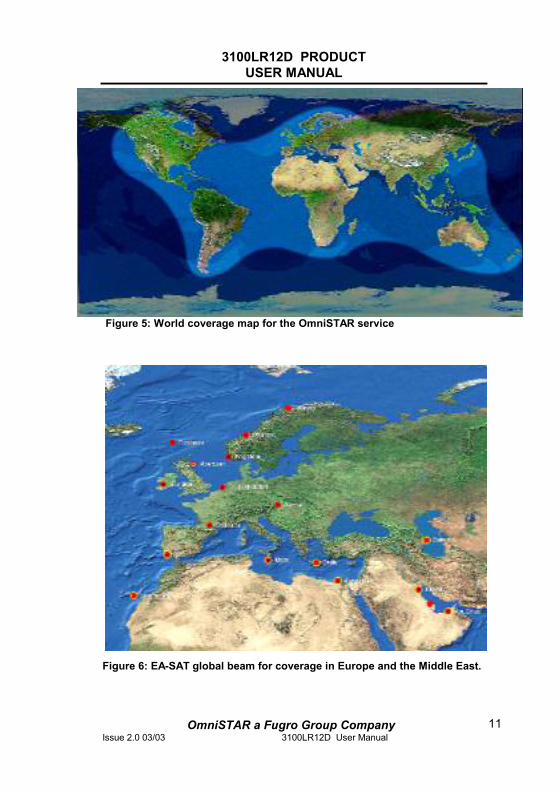
Figure 5: World coverage map for the OmniSTAR service
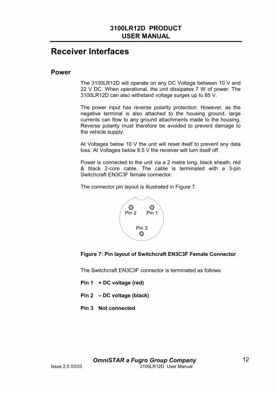
Figure 6: EA-SAT global beam for coverage in Europe and the Middle East.
3100LR12D PRODUCT USER MANUAL
OmniSTAR a Fugro Group CompanyIssue 2.0 03/03 3100LR12D User Manual
12
Receiver Interfaces
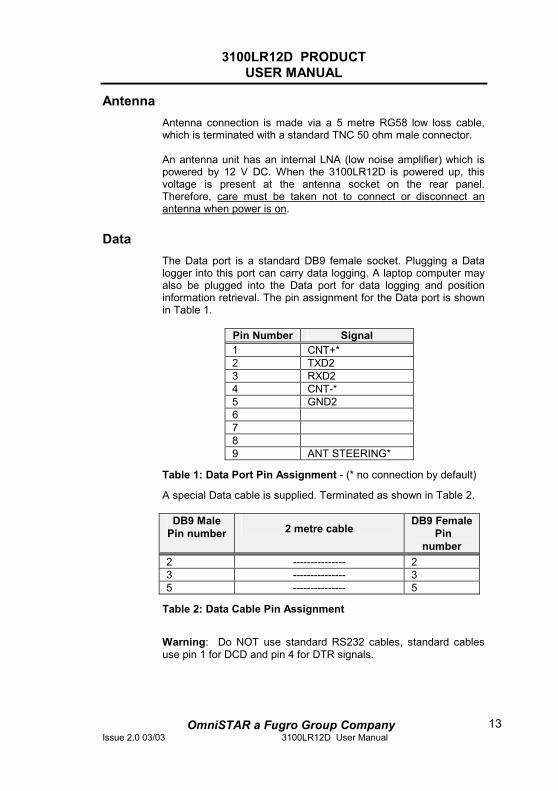
Power The 3100LR12D will operate on any DC Voltage between 10 V and 22 V DC. When operational, the unit dissipates 7 W of power. The 3100LR12D can also withstand voltage surges up to 85 V. The power input has reverse polarity protection. However, as the negative terminal is also attached to the housing ground, large currents can flow to any ground attachments made to the housing. Reverse polarity must therefore be avoided to prevent damage to the vehicle supply. At Voltages below 10 V the unit will reset itself to prevent any data loss. At Voltages below 8.5 V the receiver will turn itself off. Power is connected to the unit via a 2 metre long, black sheath, red & black 2-core cable. The cable is terminated with a 3-pin Switchcraft EN3C3F female connector. The connector pin layout is illustrated in Figure 7.
Figure 7: Pin layout of Switchcraft EN3C3F Female Connector
The Switchcraft EN3C3F connector is terminated as follows: Pin 1 + DC voltage (red) Pin 2 – DC voltage (black) Pin 3 Not connected
Pin 1
Pin 3
Pin 2
3100LR12D PRODUCT USER MANUAL
OmniSTAR a Fugro Group CompanyIssue 2.0 03/03 3100LR12D User Manual
13
Antenna Antenna connection is made via a 5 metre RG58 low loss cable, which is terminated with a standard TNC 50 ohm male connector. An antenna unit has an internal LNA (low noise amplifier) which is powered by 12 V DC. When the 3100LR12D is powered up, this voltage is present at the antenna socket on the rear panel. Therefore, care must be taken not to connect or disconnect an antenna when power is on.
Data The Data port is a standard DB9 female socket. Plugging a Data logger into this port can carry data logging. A laptop computer may also be plugged into the Data port for data logging and position information retrieval. The pin assignment for the Data port is shown in Table 1.
Pin Number Signal 1 CNT+* 2 TXD2 3 RXD2 4 CNT-* 5 GND2 6789 ANT STEERING*
Table 1: Data Port Pin Assignment - (* no connection by default)
A special Data cable is supplied. Terminated as shown in Table 2.
DB9 Male Pin number 2 metre cable
DB9 FemalePin
number 2 --------------- 2 3 --------------- 3 5 --------------- 5
Table 2: Data Cable Pin Assignment
Warning: Do NOT use standard RS232 cables, standard cables use pin 1 for DCD and pin 4 for DTR signals.
3100LR12D PRODUCT USER MANUAL
OmniSTAR a Fugro Group CompanyIssue 2.0 03/03 3100LR12D User Manual
14
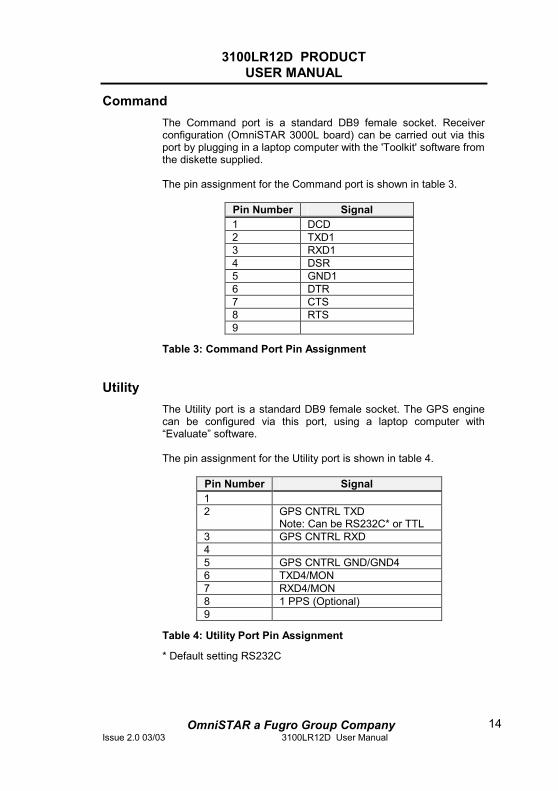
Command The Command port is a standard DB9 female socket. Receiver configuration (OmniSTAR 3000L board) can be carried out via this port by plugging in a laptop computer with the 'Toolkit' software from the diskette supplied. The pin assignment for the Command port is shown in table 3.
Pin Number Signal 1 DCD 2 TXD1 3 RXD1 4 DSR 5 GND1 6 DTR 7 CTS 8 RTS 9
Table 3: Command Port Pin Assignment
Utility The Utility port is a standard DB9 female socket. The GPS engine can be configured via this port, using a laptop computer with “Evaluate” software. The pin assignment for the Utility port is shown in table 4.
Pin Number Signal 12 GPS CNTRL TXD
Note: Can be RS232C* or TTL 3 GPS CNTRL RXD 45 GPS CNTRL GND/GND4 6 TXD4/MON 7 RXD4/MON 8 1 PPS (Optional) 9
Table 4: Utility Port Pin Assignment
* Default setting RS232C
3100LR12D PRODUCT USER MANUAL
OmniSTAR a Fugro Group CompanyIssue 2.0 03/03 3100LR12D User Manual
15
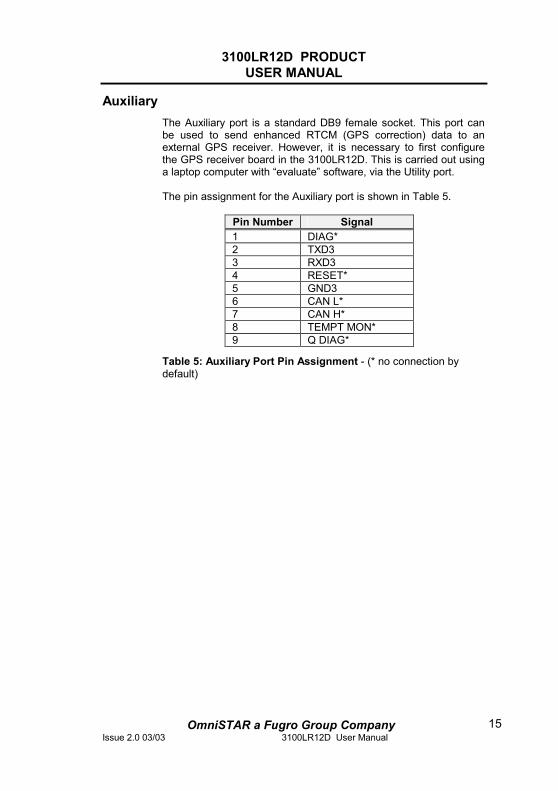
Auxiliary The Auxiliary port is a standard DB9 female socket. This port can be used to send enhanced RTCM (GPS correction) data to an external GPS receiver. However, it is necessary to first configure the GPS receiver board in the 3100LR12D. This is carried out using a laptop computer with “evaluate” software, via the Utility port. The pin assignment for the Auxiliary port is shown in Table 5.
Pin Number Signal 1 DIAG* 2 TXD3 3 RXD3 4 RESET* 5 GND3 6 CAN L* 7 CAN H* 8 TEMPT MON* 9 Q DIAG*
Table 5: Auxiliary Port Pin Assignment - (* no connection by default)

3100LR12D PRODUCT USER MANUAL
OmniSTAR a Fugro Group CompanyIssue 2.0 03/03 3100LR12D User Manual
16
Installation
Installation Considerations Before commencing installation of the 3100LR12D in a vehicle, the following should be considered:
• Determine the preferred location for each unit. Consider cable length, connector attachment space (cable bend radius), stowing excess cable, moisture, chemical corrosion, vibration and heat exposure.
• Before drilling holes, consider using existing hardware and locations where equipment was previously installed. Avoid drilling holes that may damage other equipment (e.g. structural frame members, electrical cables or fluid lines).
• High vibration and high temperature locations should be avoided whenever possible.
• In applications where vibration exceeds 5 G's acceleration, shock mounts are required. (Refer to Customer support for mounting recommendations).
• Vehicle primary power has voltages that may be harmful to personnel and equipment. Disconnect the battery cable from the battery –ve (negative) terminal before making connection to any power terminal within the vehicle.
Electrical Grounding Requirements The 3100LR12D requires a vehicle chassis connection that is a perfect ground. There should be a zero ohm reading between the receiver power socket –ve (negative) input and the point where the vehicle battery –ve (negative) terminal is connected to ground.
3100LR12D PRODUCT USER MANUAL
OmniSTAR a Fugro Group CompanyIssue 2.0 03/03 3100LR12D User Manual
17
Counter Electromagnetic Force (CEMF) A potential problem inherent in any installation of electronic systems within a vehicle is Counter Electro-magnetic Force (CEMF). CEMF is caused when relays or solenoids, connected to the vehicle DC power distribution, are de-energised. The voltage produced may exceed –400 volts. CEMF is produced by equipment such as the following:
• Electric fan brakes
• Air conditioners
• Starter relays
• Electric pump relays
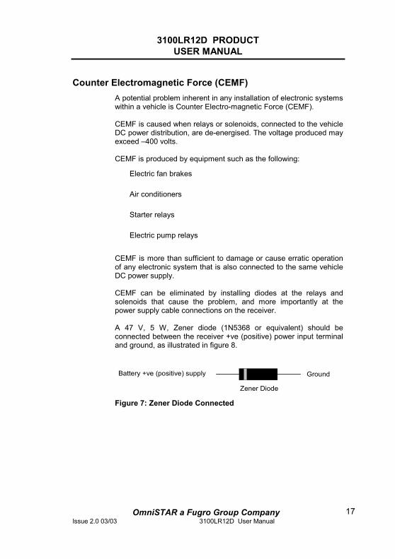
CEMF is more than sufficient to damage or cause erratic operation of any electronic system that is also connected to the same vehicle DC power supply. CEMF can be eliminated by installing diodes at the relays and solenoids that cause the problem, and more importantly at the power supply cable connections on the receiver. A 47 V, 5 W, Zener diode (1N5368 or equivalent) should be connected between the receiver +ve (positive) power input terminal and ground, as illustrated in figure 8.
Figure 7: Zener Diode Connected
GroundBattery +ve (positive) supply
Zener Diode
3100LR12D PRODUCT USER MANUAL
OmniSTAR a Fugro Group CompanyIssue 2.0 03/03 3100LR12D User Manual
18
Cable Installation
• Cables must be correctly installed for optimum system operation. Therefore, the following should be noted:
• Do not route an L-Band receiver remote antenna cable with the cabling of any other radio system. This may cause interference between both systems.
• If at all possible, do not run L-Band receiver antenna cables parallel to other radio system cabling closer than 30 centimetres.
• If cables must cross, ensure that they cross at an angle of 90 degrees. This minimises the possibility of interference.
• As far as is practicable, ensure that cables and I/O connectors are unique and fit only in their allocated location.
• Avoid routing cables along-side power generator cabling and other high electrical noise sources. This can cause interference.
• Do not kink or force cables into sharp bends that may damage the cables and cause system failure.
• After installation, ensure that excess cable is looped and clamped or tied safely away from any control cables, fuel lines, hydraulic lines or moving parts. When stowing over length cables, form loops not less than 150 mm minimum cable bend radius.
• Cable routing must avoid high temperature exposure (e.g. exhaust manifold).
3100LR12D PRODUCT USER MANUAL
OmniSTAR a Fugro Group CompanyIssue 2.0 03/03 3100LR12D User Manual
19
Antenna Location Antenna positioning is critical to system performance. The following conditions must be met for optimum system performance:
• Antenna must be mounted at least 1.5 metres away from any transmitting antennae of any frequency. Closer positioning may cause overloading of the receiver RF circuits.
• The antenna should be mounted at the highest practical point that will give a good view of the horizon and be as near horizontal as possible.
• The antenna must be located along the vehicle centre-line, or at a relevant reference point on the vehicle.
3100LR12D PRODUCT USER MANUAL
OmniSTAR a Fugro Group CompanyIssue 2.0 03/03 3100LR12D User Manual
20
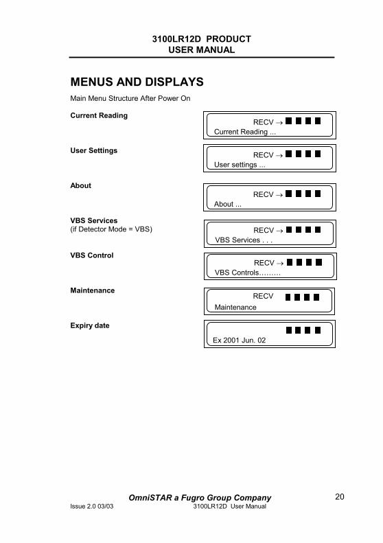
MENUS AND DISPLAYS Main Menu Structure After Power On Current Reading
User Settings
About
VBS Services (if Detector Mode = VBS)
VBS Control
Maintenance
Expiry date
Current Reading ... RECV →
User settings ... RECV →
About ...RECV →
VBS Services . . . RECV →
RECV →VBS Controls………
Maintenance RECV
Ex 2001 Jun. 02
3100LR12D PRODUCT USER MANUAL
OmniSTAR a Fugro Group CompanyIssue 2.0 03/03 3100LR12D User Manual
21
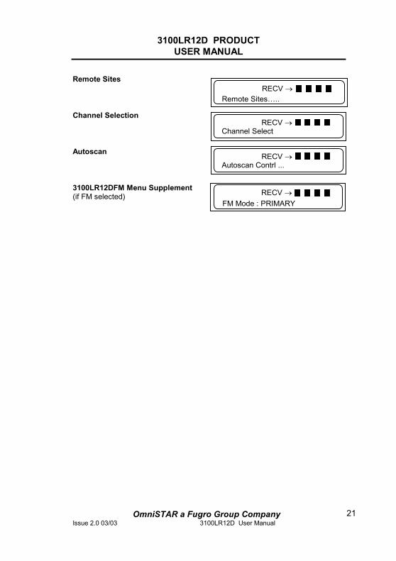
Remote Sites
Channel Selection
Autoscan
3100LR12DFM Menu Supplement (if FM selected)
RECV →Remote Sites…..
Channel Select RECV →
Autoscan Contrl ...RECV →
RECV →FM Mode : PRIMARY
3100LR12D PRODUCT USER MANUAL
OmniSTAR a Fugro Group CompanyIssue 2.0 03/03 3100LR12D User Manual
22
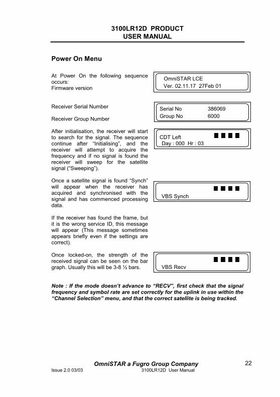
Power On Menu At Power On the following sequence occurs: Firmware version
Receiver Serial Number Receiver Group Number After initialisation, the receiver will start to search for the signal. The sequence continue after “Initialising”, and the receiver will attempt to acquire the frequency and if no signal is found the receiver will sweep for the satellite signal (“Sweeping”). Once a satellite signal is found “Synch” will appear when the receiver has acquired and synchronised with the signal and has commenced processing data. If the receiver has found the frame, but it is the wrong service ID, this message will appear (This message sometimes appears briefly even if the settings are correct). Once locked-on, the strength of the received signal can be seen on the bar graph. Usually this will be 3-8 ½ bars.
Note : If the mode doesn’t advance to “RECV”, first check that the signal frequency and symbol rate are set correctly for the uplink in use within the “Channel Selection” menu, and that the correct satellite is being tracked.
OmniSTAR LCE Ver. 02.11.17 27Feb 01
Serial No 386069 Group No 6000
Day : 000 Hr : 03 CDT Left
VBS Synch
VBS Recv
3100LR12D PRODUCT USER MANUAL
OmniSTAR a Fugro Group CompanyIssue 2.0 03/03 3100LR12D User Manual
23
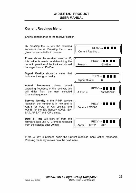
Current Readings Menu Shows performance of the receiver section
By pressing the ⇒ key the following sequence occurs. Pressing the ⇐ key gives the same fields in reverse. Power shows the receive power in dB, this value is useful in determining the correct operation of the LNA and should be larger than –115 dBm Signal Quality shows a value that indicates the signal quality.
Actual Frequency shows actual operating frequency of the receiver, this will differ from the user selected Channel frequency. Service Identity is the P-MP service identifier, the number is in hex and is x2873 for Perth or US uplinks, and xC685 for the Eik Norway AORE, EA-SAT, AF-SAT and IOR uplinks. Date & Time will start off from the firmware date until UTC time is received from the satellite after 20 min.
If the ⇒ key is pressed again the Current readings menu option reappears. Pressing the ⇓ key moves onto the next menu.
Current Reading ... RECV →
Power = -93 dBm RECV →
Signal Qual = 8 RECV →
A Freq = 1535152468 RECV →
RECV →Service Id XC685
RECV →Apr02 08:02 2001
3100LR12D PRODUCT USER MANUAL
OmniSTAR a Fugro Group CompanyIssue 2.0 03/03 3100LR12D User Manual
24
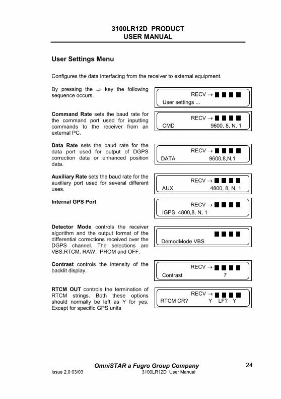
User Settings Menu Configures the data interfacing from the receiver to external equipment. By pressing the ⇒ key the following sequence occurs.
Command Rate sets the baud rate for the command port used for inputting commands to the receiver from an external PC. Data Rate sets the baud rate for the data port used for output of DGPS correction data or enhanced position data. Auxiliary Rate sets the baud rate for the auxiliary port used for several different uses. Internal GPS Port
Detector Mode controls the receiver algorithm and the output format of the differential corrections received over the DGPS channel. The selections are VBS,RTCM, RAW, PROM and OFF. Contrast controls the intensity of the backlit display.
RTCM OUT controls the termination of RTCM strings. Both these options should normally be left as Y for yes. Except for specific GPS units
User settings ... RECV →
DATA 9600,8,N,1 RECV →
DemodMode VBS
Contrast 7 RECV →
RECV →AUX 4800, 8, N, 1
RECV →CMD 9600, 8, N, 1
RECV →RTCM CR? Y LF? Y
RECV →IGPS 4800,8, N, 1
3100LR12D PRODUCT USER MANUAL
OmniSTAR a Fugro Group CompanyIssue 2.0 03/03 3100LR12D User Manual
25
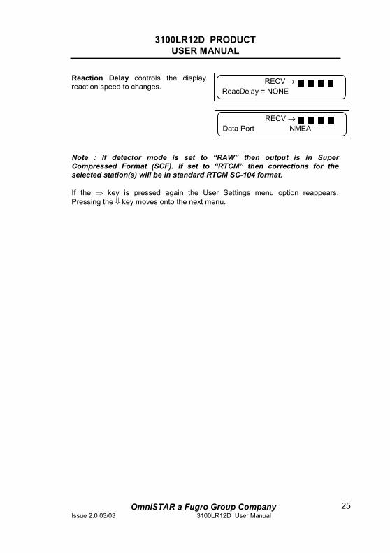
Reaction Delay controls the display reaction speed to changes.
Note : If detector mode is set to “RAW” then output is in Super Compressed Format (SCF). If set to “RTCM” then corrections for the selected station(s) will be in standard RTCM SC-104 format. If the ⇒ key is pressed again the User Settings menu option reappears. Pressing the ⇓ key moves onto the next menu.
RECV →ReacDelay = NONE
RECV →Data Port NMEA
3100LR12D PRODUCT USER MANUAL
OmniSTAR a Fugro Group CompanyIssue 2.0 03/03 3100LR12D User Manual
26
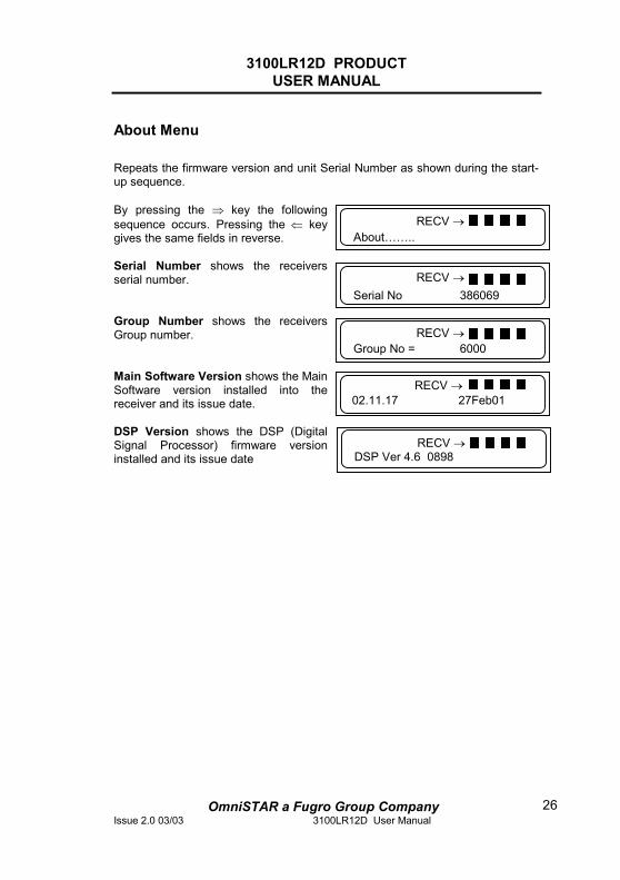
About Menu Repeats the firmware version and unit Serial Number as shown during the start-up sequence. By pressing the ⇒ key the following sequence occurs. Pressing the ⇐ key gives the same fields in reverse. Serial Number shows the receivers serial number.
Group Number shows the receivers Group number.
Main Software Version shows the Main Software version installed into the receiver and its issue date. DSP Version shows the DSP (Digital Signal Processor) firmware version installed and its issue date
About……..RECV →
Serial No 386069 RECV →
RECV →Group No = 6000
RECV →02.11.17 27Feb01
RECV →DSP Ver 4.6 0898
3100LR12D PRODUCT USER MANUAL
OmniSTAR a Fugro Group CompanyIssue 2.0 03/03 3100LR12D User Manual
27
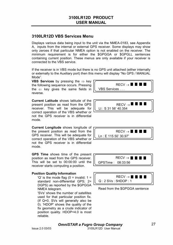
3100LR12D VBS Services Menu Displays various data being input to the unit via the NMEA-0183, see Appendix A, inputs from the internal or external GPS receiver. Some displays may show only zeroes if that particular NMEA option is not enabled on the receiver. The minimum requirement is for either the $GPGGA or $GPGLL sentences containing current position. These menus are only available if your receiver is connected to the VBS service. If the receiver is in VBS mode but there is no GPS unit attached (either internally or externally to the Auxiliary port) then this menu will display “No GPS / MANUAL Mode”. VBS Services by pressing the ⇒ key the following sequence occurs. Pressing the ⇐ key gives the same fields in reverse. Current Latitude shows latitude of the present position as read from the GPS receiver. This will be adequate for correct operation of the VBS whether or not the GPS receiver is in differential mode. Current Longitude shows longitude of the present position as read from the GPS receiver. This will be adequate for correct operation of the VBS whether or not the GPS receiver is in differential mode. GPS Time shows time of the present position as read from the GPS receiver. This will be set to 00:00:00 until the receiver starts computing a position. Position Quality Information • 'Q' is the mode flag (0 = invalid; 1 =
standard non-differential GPS; 2= DGPS) as reported by the $GPGGA NMEA telegram.
• 'SVs' shows the number of satellites used for that particular position fix. (If Q=0, SVs will generally also be 0). 'HDOP' shows the quality of the fix geometry as a crude indicator of position quality. HDOP<4.0 is most reliable.
Read from the $GPGGA sentence
VBS Services . . . RECV →
Lt : S 31 56’ 40.354 RECV →
Q : 2 SVs : 5HDOP : 1 RECV →
RECV →Ln : E 115 50’ 30.97”
RECV →GPSTime : 08:33:56
3100LR12D PRODUCT USER MANUAL
OmniSTAR a Fugro Group CompanyIssue 2.0 03/03 3100LR12D User Manual
28
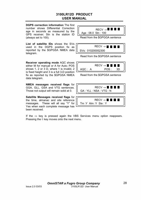
DGPS correction information The first number shows Differential Correction age in seconds as measured by the GPS receiver; Stn is the station ID (always set to 100).
Read from the $GPGGA sentence
List of satellite IDs shows the SVs used in the DGPS position fix as reported by the $GPGSA NMEA data telegram. Read from the $GPGSA sentence
Receiver operating mode AQC shows either M for manual or A for Auto; POS shows 1, 2 or 3 D, where 1 is invalid, 2 is fixed height and 3 is a full 3-D position fix as reported by the $GPGSA NMEA data telegram.
Read from the $GPGSA sentence
NMEA messages received flags for GGA, GLL, GSA and VTG sentences. Those not output will remain solid at 0. Satellite Messages received flags for the time, almanac and site reference messages. These will all say “Y” for Yes when each complete message has been received.
If the ⇒ key is pressed again the VBS Services menu option reappears. Pressing the ⇓ key moves onto the next menu.
SVs: 010200052300 RECV →
AQC : A POS : 3D RECV →
RECV →GA : YLL : NSA : VTG : N
RECV →Tm :Y Alm :Y Ste : Y
Age : 08.0 Stn : 100RECV →
3100LR12D PRODUCT USER MANUAL
OmniSTAR a Fugro Group CompanyIssue 2.0 03/03 3100LR12D User Manual
29
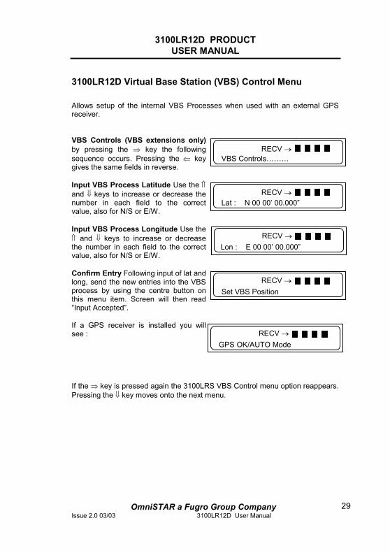
3100LR12D Virtual Base Station (VBS) Control Menu Allows setup of the internal VBS Processes when used with an external GPS receiver.
VBS Controls (VBS extensions only) by pressing the ⇒ key the following sequence occurs. Pressing the ⇐ key gives the same fields in reverse. Input VBS Process Latitude Use the ⇑and ⇓ keys to increase or decrease the number in each field to the correct value, also for N/S or E/W. Input VBS Process Longitude Use the ⇑ and ⇓ keys to increase or decrease the number in each field to the correct value, also for N/S or E/W. Confirm Entry Following input of lat and long, send the new entries into the VBS process by using the centre button on this menu item. Screen will then read “Input Accepted”. If a GPS receiver is installed you will see :
If the ⇒ key is pressed again the 3100LRS VBS Control menu option reappears. Pressing the ⇓ key moves onto the next menu.
Lat : N 00 00’ 00.000” RECV →
Lon : E 00 00’ 00.000” RECV →
Set VBS Position RECV →
RECV →VBS Controls………
GPS OK/AUTO Mode RECV →
3100LR12D PRODUCT USER MANUAL
OmniSTAR a Fugro Group CompanyIssue 2.0 03/03 3100LR12D User Manual
30
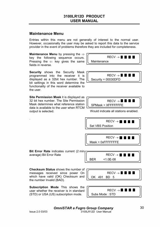
Maintenance Menu Entries within this menu are not generally of interest to the normal user. However, occasionally the user may be asked to report this data to the service provider in the event of problems therefore they are included for completeness. Maintenance Menu by pressing the ⇒key the following sequence occurs. Pressing the ⇐ key gives the same fields in reverse. Security shows the Security Mask programmed into the receiver it is displayed as a 32bit hex number. The bit settings in this word determine the functionality of the receiver available to the user. Site Permission Mask it is displayed as 32 bit hex number. The Site Permission Mask determines what reference station data is available to the user when RTCM output is selected.
Would indicate all stations enabled.
.
Bit Error Rate indicates current (2 min average) Bit Error Rate
Checksum Status shows the number of messages received since power On which have valid (OK) Checksum and the number Invalid (BAD). Subscription Mode This shows the user whether the receiver is in standard (STD) or USA (US) subscription mode.
Maintenance RECV →
Security = 00030DFD RECV →
SPMask = XFFFFFFFE RECV →
RECV →OK 491 BD 5
RECV →Subs Mode : STD
Set VBS Position RECV →
Mask = 0xFFFFFFFE RECV →
BER <1.0E-08 RECV →
3100LR12D PRODUCT USER MANUAL
OmniSTAR a Fugro Group CompanyIssue 2.0 03/03 3100LR12D User Manual
31
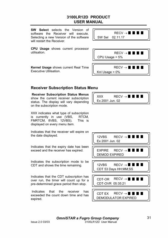
SW Select selects the Version of software the Receiver will execute. Selecting a new Version of the software will restart the Receiver. CPU Usage shows current processor utilisation.
Kernel Usage shows current Real Time Executive Utilisation.
Receiver Subscription Status Menu Receiver Subscription Status Menus show the current receiver subscription status. The display will vary depending on the subscription mode. XXX indicates what type of subscription is currently in use (VBS, RTCM, FMRTCM, 8VBS, 12VBS). This is displayed on every menu item. Indicates that the receiver will expire on the date displayed.
Indicates that the expiry date has been exceed and the receiver has expired.
Indicates the subscription mode to be CDT and shows the time remaining.
Indicates that the CDT subscription has over run, the timer will count up for a pre-determined grace period then stop. Indicates that the receiver has
exceeded the count down time and has expired.
RECV →Knl Usage = 0%
EXPIREDEMOD EXPIRED
RECV →
RECV →SW Sel 02.11.17
RECV →CPU Usage = 5%
XXXEx 2001 Jun. 02
RECV →
12VBS Ex 2001 Jun. 02
RECV →
CDT-OVR 05:35:21 CDT-OR RECV →
CDT EXDEMODULATOR EXPIRED
RECV →
12VBS CDT 53 Days HH:MM;SS
RECV →
3100LR12D PRODUCT USER MANUAL
OmniSTAR a Fugro Group CompanyIssue 2.0 03/03 3100LR12D User Manual
32
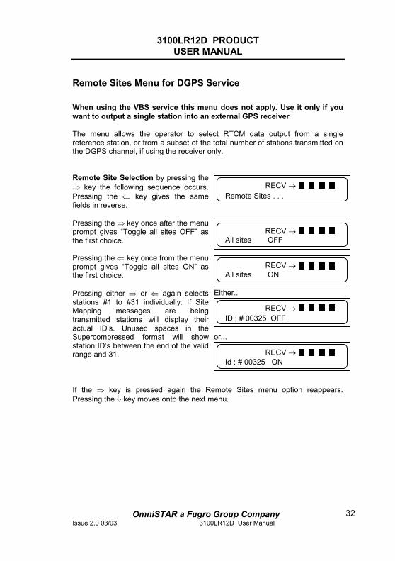
Remote Sites Menu for DGPS Service When using the VBS service this menu does not apply. Use it only if you want to output a single station into an external GPS receiver The menu allows the operator to select RTCM data output from a single reference station, or from a subset of the total number of stations transmitted on the DGPS channel, if using the receiver only.
Remote Site Selection by pressing the ⇒ key the following sequence occurs. Pressing the ⇐ key gives the same fields in reverse. Pressing the ⇒ key once after the menu prompt gives “Toggle all sites OFF” as the first choice.
Pressing the ⇐ key once from the menu prompt gives “Toggle all sites ON” as the first choice. Pressing either ⇒ or ⇐ again selects stations #1 to #31 individually. If Site Mapping messages are being transmitted stations will display their actual ID’s. Unused spaces in the Supercompressed format will show station ID’s between the end of the valid range and 31.
Either..
or...
If the ⇒ key is pressed again the Remote Sites menu option reappears. Pressing the ⇓ key moves onto the next menu.
All sites OFF RECV →
Id : # 00325 ON RECV →
ID ; # 00325 OFF RECV →
RECV →All sites ON
RECV →Remote Sites . . .
3100LR12D PRODUCT USER MANUAL
OmniSTAR a Fugro Group CompanyIssue 2.0 03/03 3100LR12D User Manual
33
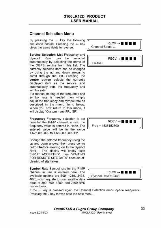
Channel Selection Menu By pressing the ⇒ key the following sequence occurs. Pressing the ⇐ key gives the same fields in reverse. Service Selection List Frequency and Symbol Rate can be selected automatically by selecting the name of the DGPS service from this list. The currently selected item can be changed by using the up and down arrows to scroll through the list. Pressing the centre button selects the currently displayed item as the service, and automatically sets the frequency and symbol rate. If a manual setting of the frequency and symbol rate is needed then simply adjust the frequency and symbol rate as described in the menu items below. When you next return to this menu, it will display “Custom - see FR / SR”. Frequency Frequency selection is set here for the P-MP channel in use, the frequency value is entered in Hertz. The entered value will be in the range 1,525,000,000 to 1,559,000,000 Hz. Change the entered frequency using the up and down arrows, then press centre button before moving on to the Symbol Rate - The display will briefly flash “INPUT ACCEPTED”, then “WAITING FOR REMOTE SITE DATA” because of clearing of site tables. Symbol Rate Symbol rate for the P-MP channel in use is entered here. The available options are 609, 1219, 2438, 4876 which equate to user satellite data rates of 300, 600, 1200, and 2400 BPS respectively.
If the ⇒ key is pressed again the Channel Selection menu option reappears. Pressing the ⇓ key moves onto the next menu.
Channel Select ... RECV →
EA-SAT RECV →
Freq = 1535152500 RECV →
Symbol Rate = 2438 RECV →
3100LR12D PRODUCT USER MANUAL
OmniSTAR a Fugro Group CompanyIssue 2.0 03/03 3100LR12D User Manual
34
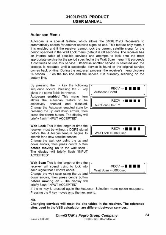
Autoscan Menu Autoscan is a special feature, which allows the 3100LR12D Receiver’s to automatically search for another satellite signal to use. This feature only starts if it is enabled and if the receiver cannot lock the current satellite signal for the period specified in the Wait Lock menu (default is 60 seconds). The receiver has an internal table of possible services and attempts to lock onto the most appropriate service for the period specified in the Wait Scan menu. If it succeeds it continues to use this service. Otherwise another service is selected and the process is repeated until a successful service is found or the original service comes back on-line. During the autoscan process, the receiver’s menu displays “Autoscan …” on the top line and the service it is currently scanning on the bottom line. By pressing the ⇒ key the following sequence occurs. Pressing the ⇐ key gives the same fields in reverse.
Autoscan enabled This menu item allows the autoscan feature to be selectively enabled and disabled. Change the Autoscan enabled state by pressing the up and down arrows, then press the centre button. The display will briefly flash “INPUT ACCEPTED”. Wait Lock This is the length of time the receiver must be without a DGPS signal before the Autoscan feature begins to search for a new satellite service. Change the wait lock using the up and down arrows, then press centre button before moving on to the wait scan - The display will briefly flash “INPUT ACCEPTED” Wait Scan This is the length of time the receiver will spend trying to lock into each signal that it knows about. Change the wait scan using the up and down arrows, then press centre button before moving on - The display will briefly flash “INPUT ACCEPTED”
If the ⇒ key is pressed again the Autoscan Selection menu option reappears. Pressing the ⇓ key moves onto the next menu. NB. Changing services will reset the site tables in the receiver. The reference sites used in the VBS calculation are different between services.
Autoscan Contrl ...RECV →
AutoScan On? YRECV →
Wait Lock = 00600sec RECV →
Wait Scan = 00030sec RECV →
3100LR12D PRODUCT USER MANUAL
OmniSTAR a Fugro Group CompanyIssue 2.0 03/03 3100LR12D User Manual
35
Receiver Service Procedure
If an OmniSTAR Receiver unit fails to perform, contact OmniSTAR BV after following the procedural checks. We wish to hear about frequently experienced problems, and your assistance will help by copying the form, see Appendix D, filling in the details requested and faxing or mailing the form to OmniSTAR BV. The most common problems are interfacing, and usually occur at installation time. If you have an interfacing connection not covered in this manual we would like to assist you and produce another technical bulletin that may assist other users in the future. If a problem appears that you think may be caused by a system performance problem, contact OmniSTAR BV for any system aberrations that may have been experienced. We are sensitive to our customers’ needs and we want to assure specified system performance at all times. There could, however, be situations where conditions are below par, such as fringe area operations, radio communication disturbance etc., and, as OmniSTAR BV monitors the receiver system performance continuously, these conditions would be noted.
3100LR12D PRODUCT USER MANUAL
OmniSTAR a Fugro Group CompanyIssue 2.0 03/03 3100LR12D User Manual
36
Technical Specifications Receive Frequency Automatic Scanning: 1525 MHz to 1559 MHz Environment Operating Temperature: -20° to 65°C Non-operating: -40° to 85°C Humidity: 95% non-condensing Vibration: 3G/30 Hz/x, y & z axes Shock: Max 7G, 5-20 msec zero rebound Acceleration: 4G (with optional software) Data inputs and outputs Four Serial Ports: Command, Data, Auxiliary & Utility Electrical Interference: RS-232-C Data Rates: 300, 600, 1200, 2400, 4800, 9600, 19200, 38400, 56700 Message Rate: 1 Hz or 5 Hz, 10 Hz and 20 Hz optional Plug Types: DB9 Connectors RF Input to Receiver: TNC female Power Connector: Switchcraft En3C3F Power Power Supply: 10 V DC to 22 V DC Power Consumption: 250 - 500 mA at 12 V DC Physical Characteristics Dimensions (approx.): Height 60 mm Width 150 mm Length 225 mm Weight (approx.): 1.25 kilogram Display: LCD Approvals Complies with European and USA EMI/EMC
3100LR12D PRODUCT USER MANUAL
OmniSTAR a Fugro Group CompanyIssue 2.0 03/03 3100LR12D User Manual
37
Acronyms Used In This Manual CEMF Counter Electro-magnetic Force DGPS Differential Global Positioning System GGA Global Positioning System fixed data (NMEA standard) GLL Geographic position (NMEA standard) GPS Global Positioning System GSA Global Positioning System, dilution of position, active
satellite (NMEA standard) GSV GPS satellites in view (NMEA standard) LCD Liquid Cristal Display LNA Low Noise Amplifier NCC Network Control Centre NMEA National Marine Electronics Association (Standard for
interfacing marine electronic devices) RF Radio Frequency RTCM Radio Technical Commission Maritime VTG Track mode good' and 'ground speed' (NMEA Standard) ZDA Time and date (NMEA standard)
3100LR12D PRODUCT USER MANUAL
OmniSTAR a Fugro Group CompanyIssue 2.0 03/03 3100LR12D User Manual
38
APPENDIX A
NMEA 0183 Introduction
NMEA 0183 is an interface protocol created by the National Marine Electronics Association. The latest release of NMEA 0183 is Version 3.0. This protocol was originally established to allow marine navigation equipment to share information. NMEA 0183 is a simple, yet comprehensive ASCII protocol, which defines both the communication interface and the data format.
This appendix provides a brief overview of the NMEA protocol and describes both the standard and optional messages offered by the GPS receiver employed in the 3100LR12D DGPS Receiver.
3100LR12D PRODUCT USER MANUAL
OmniSTAR a Fugro Group CompanyIssue 2.0 03/03 3100LR12D User Manual
39
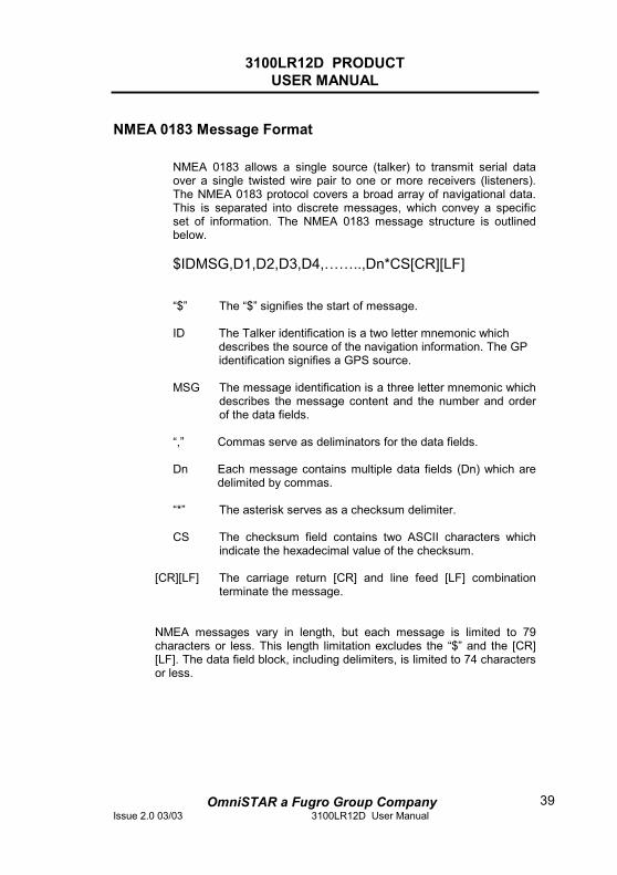
NMEA 0183 Message Format
NMEA 0183 allows a single source (talker) to transmit serial data over a single twisted wire pair to one or more receivers (listeners). The NMEA 0183 protocol covers a broad array of navigational data. This is separated into discrete messages, which convey a specific set of information. The NMEA 0183 message structure is outlined below.
$IDMSG,D1,D2,D3,D4,……..,Dn*CS[CR][LF]
“$” The “$” signifies the start of message.
ID The Talker identification is a two letter mnemonic which
describes the source of the navigation information. The GP identification signifies a GPS source.
MSG The message identification is a three letter mnemonic which
describes the message content and the number and order of the data fields.
“,” Commas serve as deliminators for the data fields.
Dn Each message contains multiple data fields (Dn) which are
delimited by commas.
“*” The asterisk serves as a checksum delimiter.
CS The checksum field contains two ASCII characters which indicate the hexadecimal value of the checksum.
[CR][LF] The carriage return [CR] and line feed [LF] combination
terminate the message.
NMEA messages vary in length, but each message is limited to 79 characters or less. This length limitation excludes the “$” and the [CR] [LF]. The data field block, including delimiters, is limited to 74 characters or less.
3100LR12D PRODUCT USER MANUAL
OmniSTAR a Fugro Group CompanyIssue 2.0 03/03 3100LR12D User Manual
40
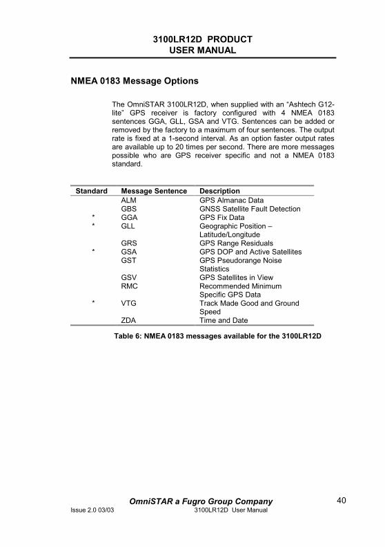
NMEA 0183 Message Options
The OmniSTAR 3100LR12D, when supplied with an “Ashtech G12-lite” GPS receiver is factory configured with 4 NMEA 0183 sentences GGA, GLL, GSA and VTG. Sentences can be added or removed by the factory to a maximum of four sentences. The output rate is fixed at a 1-second interval. As an option faster output rates are available up to 20 times per second. There are more messages possible who are GPS receiver specific and not a NMEA 0183 standard.
Standard Message Sentence Description ALM GPS Almanac Data GBS GNSS Satellite Fault Detection
* GGA GPS Fix Data * GLL Geographic Position –
Latitude/Longitude GRS GPS Range Residuals * GSA GPS DOP and Active Satellites GST GPS Pseudorange Noise
Statistics GSV GPS Satellites in View RMC Recommended Minimum
Specific GPS Data * VTG Track Made Good and Ground
Speed ZDA Time and Date
Table 6: NMEA 0183 messages available for the 3100LR12D
3100LR12D PRODUCT USER MANUAL
OmniSTAR a Fugro Group CompanyIssue 2.0 03/03 3100LR12D User Manual
41
NMEA 0183 Message Formats
In this section each message is described in more detail.
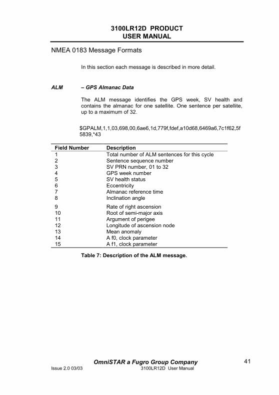
ALM – GPS Almanac Data
The ALM message identifies the GPS week, SV health and contains the almanac for one satellite. One sentence per satellite, up to a maximum of 32.
$GPALM,1,1,03,698,00,6ae6,1d,779f,fdef,a10d68,6469a6,7c1f62,5f5839,*43
Field Number Description 1 Total number of ALM sentences for this cycle 2 Sentence sequence number 3 SV PRN number, 01 to 32 4 GPS week number 5 SV health status 6 Eccentricity 7 Almanac reference time 8 Inclination angle 9 Rate of right ascension 10 Root of semi-major axis 11 Argument of perigee 12 Longitude of ascension node 13 Mean anomaly 14 A f0, clock parameter 15 A f1, clock parameter
Table 7: Description of the ALM message.
3100LR12D PRODUCT USER MANUAL
OmniSTAR a Fugro Group CompanyIssue 2.0 03/03 3100LR12D User Manual
42
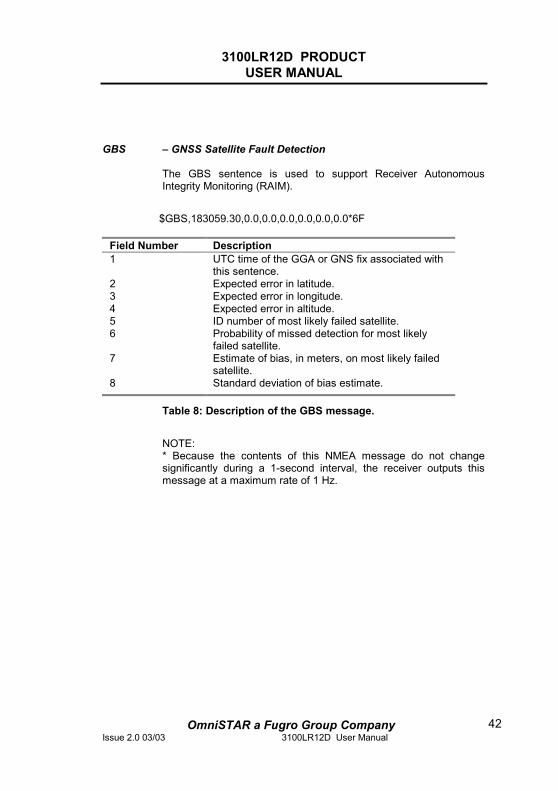
GBS – GNSS Satellite Fault Detection
The GBS sentence is used to support Receiver Autonomous Integrity Monitoring (RAIM).
$GBS,183059.30,0.0,0.0,0.0,0.0,0.0,0.0*6F
Field Number Description 1 UTC time of the GGA or GNS fix associated with
this sentence. 2 Expected error in latitude. 3 Expected error in longitude. 4 Expected error in altitude. 5 ID number of most likely failed satellite. 6 Probability of missed detection for most likely
failed satellite. 7 Estimate of bias, in meters, on most likely failed
satellite. 8 Standard deviation of bias estimate.
Table 8: Description of the GBS message.
NOTE: * Because the contents of this NMEA message do not change significantly during a 1-second interval, the receiver outputs this message at a maximum rate of 1 Hz.
3100LR12D PRODUCT USER MANUAL
OmniSTAR a Fugro Group CompanyIssue 2.0 03/03 3100LR12D User Manual
43
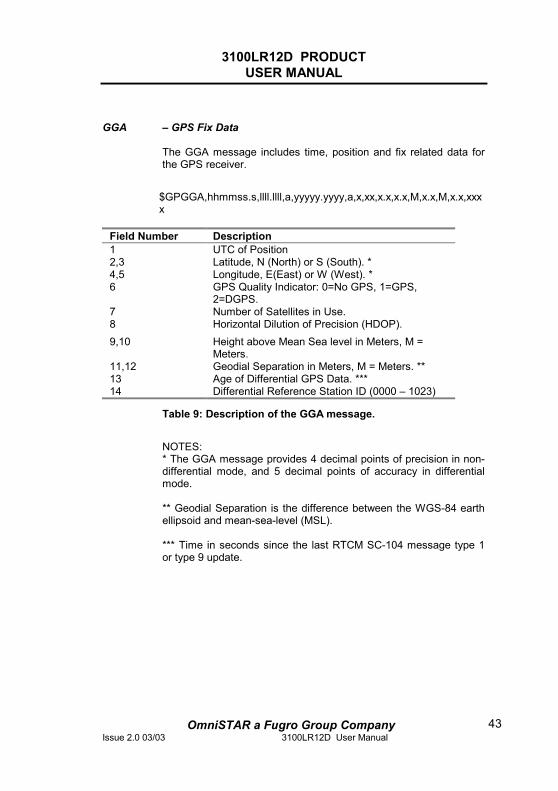
GGA – GPS Fix Data
The GGA message includes time, position and fix related data for the GPS receiver.
$GPGGA,hhmmss.s,llll.llll,a,yyyyy.yyyy,a,x,xx,x.x,x.x,M,x.x,M,x.x,xxxx
Field Number Description 1 UTC of Position 2,3 Latitude, N (North) or S (South). * 4,5 Longitude, E(East) or W (West). * 6 GPS Quality Indicator: 0=No GPS, 1=GPS,
2=DGPS. 7 Number of Satellites in Use. 8 Horizontal Dilution of Precision (HDOP). 9,10 Height above Mean Sea level in Meters, M =
Meters. 11,12 Geodial Separation in Meters, M = Meters. ** 13 Age of Differential GPS Data. *** 14 Differential Reference Station ID (0000 – 1023)
Table 9: Description of the GGA message.
NOTES: * The GGA message provides 4 decimal points of precision in non-differential mode, and 5 decimal points of accuracy in differential mode. ** Geodial Separation is the difference between the WGS-84 earth ellipsoid and mean-sea-level (MSL). *** Time in seconds since the last RTCM SC-104 message type 1 or type 9 update.
3100LR12D PRODUCT USER MANUAL
OmniSTAR a Fugro Group CompanyIssue 2.0 03/03 3100LR12D User Manual
44
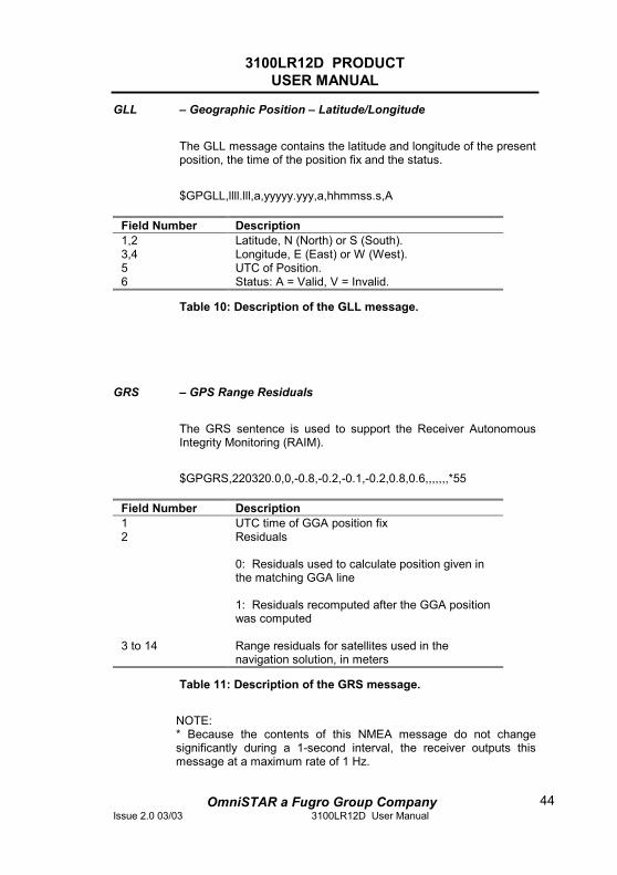
GLL – Geographic Position – Latitude/Longitude
The GLL message contains the latitude and longitude of the present position, the time of the position fix and the status.
$GPGLL,llll.lll,a,yyyyy.yyy,a,hhmmss.s,A
Field Number Description 1,2 Latitude, N (North) or S (South). 3,4 Longitude, E (East) or W (West). 5 UTC of Position. 6 Status: A = Valid, V = Invalid.
Table 10: Description of the GLL message.
GRS – GPS Range Residuals
The GRS sentence is used to support the Receiver Autonomous Integrity Monitoring (RAIM).
$GPGRS,220320.0,0,-0.8,-0.2,-0.1,-0.2,0.8,0.6,,,,,,,*55
Field Number Description 1 UTC time of GGA position fix 2 Residuals
0: Residuals used to calculate position given in the matching GGA line 1: Residuals recomputed after the GGA position was computed
3 to 14 Range residuals for satellites used in the navigation solution, in meters
Table 11: Description of the GRS message.
NOTE: * Because the contents of this NMEA message do not change significantly during a 1-second interval, the receiver outputs this message at a maximum rate of 1 Hz.
3100LR12D PRODUCT USER MANUAL
OmniSTAR a Fugro Group CompanyIssue 2.0 03/03 3100LR12D User Manual
45
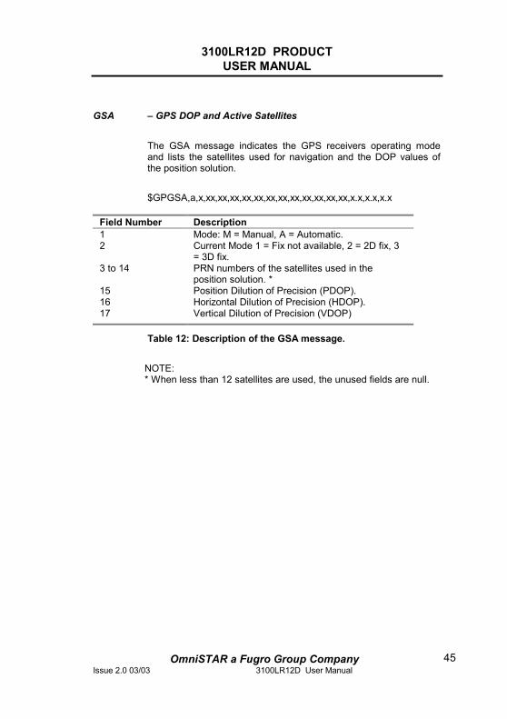
GSA – GPS DOP and Active Satellites
The GSA message indicates the GPS receivers operating mode and lists the satellites used for navigation and the DOP values of the position solution.
$GPGSA,a,x,xx,xx,xx,xx,xx,xx,xx,xx,xx,xx,xx,xx,x.x,x.x,x.x
Field Number Description 1 Mode: M = Manual, A = Automatic. 2 Current Mode 1 = Fix not available, 2 = 2D fix, 3
= 3D fix. 3 to 14 PRN numbers of the satellites used in the
position solution. * 15 Position Dilution of Precision (PDOP). 16 Horizontal Dilution of Precision (HDOP). 17 Vertical Dilution of Precision (VDOP)
Table 12: Description of the GSA message.
NOTE: * When less than 12 satellites are used, the unused fields are null.
3100LR12D PRODUCT USER MANUAL
OmniSTAR a Fugro Group CompanyIssue 2.0 03/03 3100LR12D User Manual
46
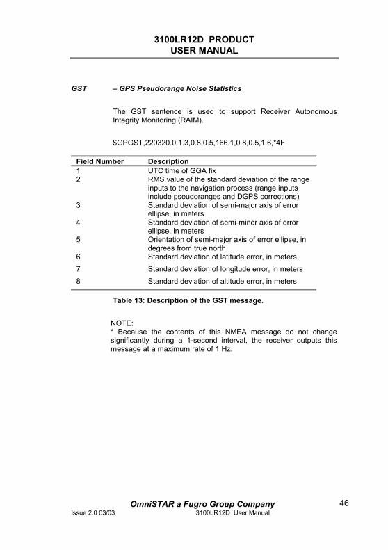
GST – GPS Pseudorange Noise Statistics
The GST sentence is used to support Receiver Autonomous Integrity Monitoring (RAIM).
$GPGST,220320.0,1.3,0.8,0.5,166.1,0.8,0.5,1.6,*4F
Field Number Description 1 UTC time of GGA fix 2 RMS value of the standard deviation of the range
inputs to the navigation process (range inputs include pseudoranges and DGPS corrections)
3 Standard deviation of semi-major axis of error ellipse, in meters
4 Standard deviation of semi-minor axis of error ellipse, in meters
5 Orientation of semi-major axis of error ellipse, in degrees from true north
6 Standard deviation of latitude error, in meters 7 Standard deviation of longitude error, in meters 8 Standard deviation of altitude error, in meters
Table 13: Description of the GST message.
NOTE: * Because the contents of this NMEA message do not change significantly during a 1-second interval, the receiver outputs this message at a maximum rate of 1 Hz.
3100LR12D PRODUCT USER MANUAL
OmniSTAR a Fugro Group CompanyIssue 2.0 03/03 3100LR12D User Manual
47
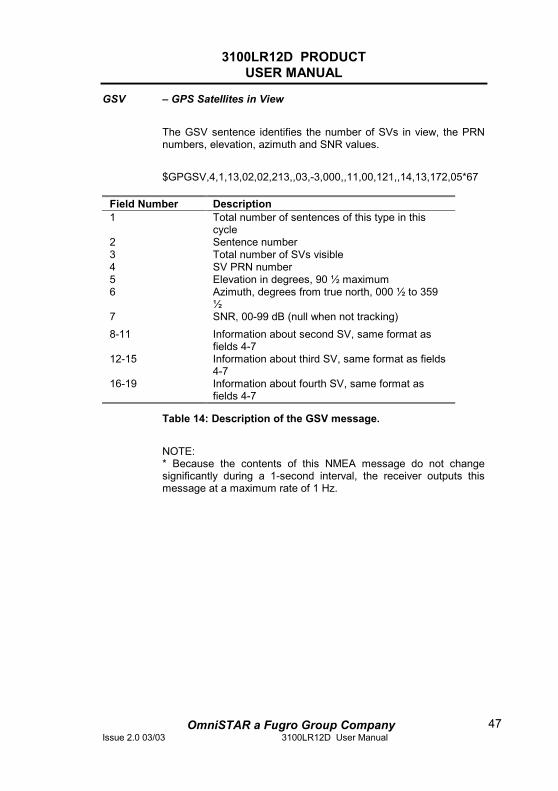
GSV – GPS Satellites in View
The GSV sentence identifies the number of SVs in view, the PRN numbers, elevation, azimuth and SNR values.
$GPGSV,4,1,13,02,02,213,,03,-3,000,,11,00,121,,14,13,172,05*67
Field Number Description 1 Total number of sentences of this type in this
cycle 2 Sentence number 3 Total number of SVs visible 4 SV PRN number 5 Elevation in degrees, 90 ½ maximum 6 Azimuth, degrees from true north, 000 ½ to 359
½7 SNR, 00-99 dB (null when not tracking) 8-11 Information about second SV, same format as
fields 4-7 12-15 Information about third SV, same format as fields
4-7 16-19 Information about fourth SV, same format as
fields 4-7
Table 14: Description of the GSV message.
NOTE: * Because the contents of this NMEA message do not change significantly during a 1-second interval, the receiver outputs this message at a maximum rate of 1 Hz.
3100LR12D PRODUCT USER MANUAL
OmniSTAR a Fugro Group CompanyIssue 2.0 03/03 3100LR12D User Manual
48
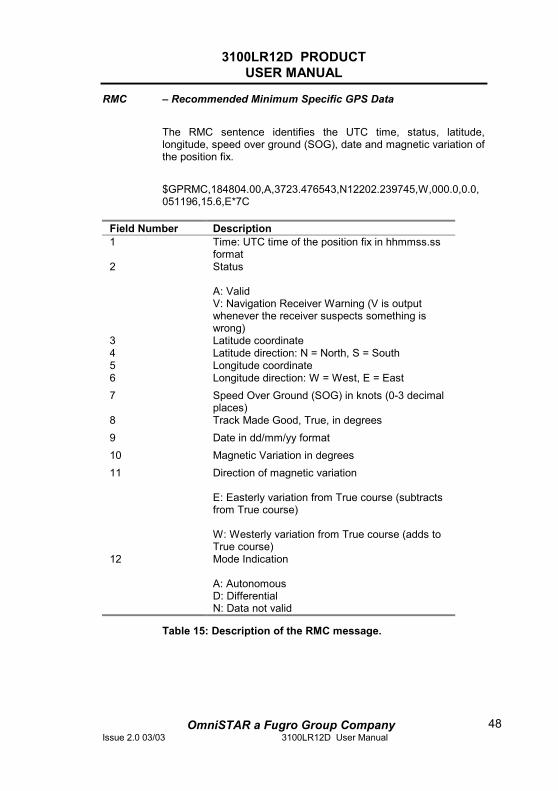
RMC – Recommended Minimum Specific GPS Data
The RMC sentence identifies the UTC time, status, latitude, longitude, speed over ground (SOG), date and magnetic variation of the position fix.
$GPRMC,184804.00,A,3723.476543,N12202.239745,W,000.0,0.0,051196,15.6,E*7C
Field Number Description 1 Time: UTC time of the position fix in hhmmss.ss
format 2 Status
A: Valid V: Navigation Receiver Warning (V is output whenever the receiver suspects something is wrong)
3 Latitude coordinate 4 Latitude direction: N = North, S = South 5 Longitude coordinate 6 Longitude direction: W = West, E = East 7 Speed Over Ground (SOG) in knots (0-3 decimal
places) 8 Track Made Good, True, in degrees 9 Date in dd/mm/yy format 10 Magnetic Variation in degrees 11 Direction of magnetic variation
E: Easterly variation from True course (subtracts from True course) W: Westerly variation from True course (adds to True course)
12 Mode Indication A: Autonomous D: Differential N: Data not valid
Table 15: Description of the RMC message.
3100LR12D PRODUCT USER MANUAL
OmniSTAR a Fugro Group CompanyIssue 2.0 03/03 3100LR12D User Manual
49
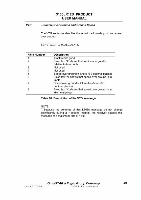
VTG – Course Over Ground and Ground Speed
The VTG sentence identifies the actual track made good and speed over ground.
$GPVTG,0,T,,,0.00,N,0.00,K*33
Field Number Description 1 Track made good 2 Fixed text ‘T’ shows that track made good is
relative to true north 3 Not used 4 Not used 5 Speed over ground in knots (0-3 decimal places) 6 Fixed text ‘N’ shows that speed over ground is in
knots 7 Speed over ground in kilometers/hour (0-3
decimal places) 8 Fixed text ‘K’ shows that speed over ground is in
kilometers/hour
Table 16: Description of the VTG message.
NOTE: * Because the contents of this NMEA message do not change significantly during a 1-second interval, the receiver outputs this message at a maximum rate of 1 Hz.
3100LR12D PRODUCT USER MANUAL
OmniSTAR a Fugro Group CompanyIssue 2.0 03/03 3100LR12D User Manual
50
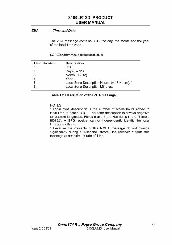
ZDA – Time and Date
The ZDA message contains UTC, the day, the month and the year of the local time zone.
$GPZDA,hhmmss.s,xx,xx,xxxx,xx,xx
Field Number Description 1 UTC. 2 Day (0 – 31). 3 Month (0 – 12). 4 Year. 5 Local Zone Description Hours (± 13 Hours). * 6 Local Zone Description Minutes.
Table 17: Description of the ZDA message.
NOTES: * Local zone description is the number of whole hours added to local time to obtain UTC. The zone description is always negative for eastern longitudes. Fields 5 and 6 are Null fields in the “Trimble BD132”. A GPS receiver cannot independently identify the local time zone offsets. * Because the contents of this NMEA message do not change significantly during a 1-second interval, the receiver outputs this message at a maximum rate of 1 Hz.
3100LR12D PRODUCT USER MANUAL
OmniSTAR a Fugro Group CompanyIssue 2.0 03/03 3100LR12D User Manual
51
Appendix B
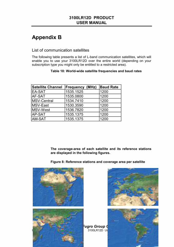
List of communication satellites The following table presents a list of L-band communication satellites, which will enable you to use your 3100LR12D over the entire world (depending on your subscription type you might only be entitled to a restricted area).
Table 18: World-wide satellite frequencies and baud rates
Satellite Channel Frequency (MHz) Baud Rate EA-SAT 1535.1525 1200 AF-SAT 1535.0800 1200 MSV-Central 1534.7410 1200 MSV-East 1530.3590 1200 MSV-West 1536.7820 1200 AP-SAT 1535.1375 1200 AM-SAT 1535.1375 1200
The coverage-area of each satellite and its reference stations are displayed in the following figures.
Figure 8: Reference stations and coverage area per satellite
AF-SAT EA-SAT
3100LR12D PRODUCT USER MANUAL
OmniSTAR a Fugro Group CompanyIssue 2.0 03/03 3100LR12D User Manual
52
AP-SAT AM-SAT
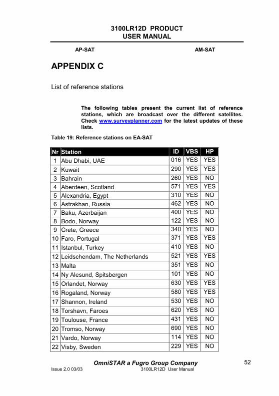
APPENDIX C
List of reference stations
The following tables present the current list of reference stations, which are broadcast over the different satellites. Check www.surveyplanner.com for the latest updates of these lists.
Table 19: Reference stations on EA-SAT
Nr Station ID VBS HP 1 Abu Dhabi, UAE 016 YES YES
2 Kuwait 290 YES YES3 Bahrain 260 YES NO 4 Aberdeen, Scotland 571 YES YES5 Alexandria, Egypt 310 YES NO 6 Astrakhan, Russia 462 YES NO 7 Baku, Azerbaijan 400 YES NO 8 Bodo, Norway 122 YES NO 9 Crete, Greece 340 YES NO
10 Faro, Portugal 371 YES YES
11 Istanbul, Turkey 410 YES NO
12 Leidschendam, The Netherlands 521 YES YES
13 Malta 351 YES NO
14 Ny Alesund, Spitsbergen 101 YES NO
15 Orlandet, Norway 630 YES YES
16 Rogaland, Norway 580 YES YES
17 Shannon, Ireland 530 YES NO
18 Torshavn, Faroes 620 YES NO
19 Toulouse, France 431 YES NO
20 Tromso, Norway 690 YES NO
21 Vardo, Norway 114 YES NO
22 Visby, Sweden 229 YES NO

3100LR12D PRODUCT USER MANUAL
OmniSTAR a Fugro Group CompanyIssue 2.0 03/03 3100LR12D User Manual
53
23 Vienna, Austria 480 YES NO
Table 20: Reference stations on AF-SAT
Nr Station ID VBS HP 1 Abidjan, Ivory Coast 050 YES NO
2 Blantyre, Malawi 155 YES NO 3 Cape Town, South Africa 335 YES NO 4 Dakar, Senegal 144 YES NO 5 Douala, Cameroon 043 YES YES6 Durban, South Africa 305 YES NO 7 Faro, Portugal 371 YES NO 8 Lagos, Nigeria 060 YES NO 9 Las Palmas, Canaries 280 YES NO
10 Luanda, Angola 095 YES YES
11 Nairobi, Kenya 015 YES NO
13 Pointe-Noire, Congo 045 YES YES
14 Port Elizabeth, South Africa 337 YES NO
15 Rogaland, Norway 580 YES YES
16 Sao Tome, Sao Tome 011 YES YES
17 Walvis Bay, Namibia 235 YES NO
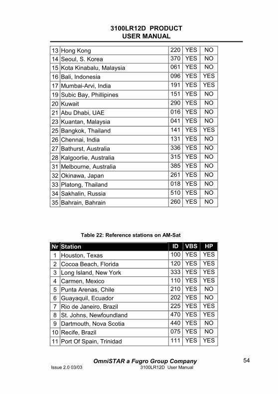
Table 21: Reference stations on AP-Sat
Nr Station ID VBS HP 1 Auckland, NZ 022 YES NO
2 Karratha, Australia 215 YES NO 3 Darwin, Australia 125 YES NO 4 Broome, Australia 185 YES NO 9 Asahikawa, Japan 261 YES NO
10 Singapore 010 YES YES11 Miri, Malaysia 042 YES YES12 Vung Tua, Vietnam 012 YES YES
3100LR12D PRODUCT USER MANUAL
OmniSTAR a Fugro Group CompanyIssue 2.0 03/03 3100LR12D User Manual
54
13 Hong Kong 220 YES NO 14 Seoul, S. Korea 370 YES NO 15 Kota Kinabalu, Malaysia 061 YES NO
16 Bali, Indonesia 096 YES YES
17 Mumbai-Arvi, India 191 YES YES
19 Subic Bay, Phillipines 151 YES NO
20 Kuwait 290 YES NO
21 Abu Dhabi, UAE 016 YES NO
23 Kuantan, Malaysia 041 YES NO
25 Bangkok, Thailand 141 YES YES
26 Chennai, India 131 YES NO
27 Bathurst, Australia 336 YES NO
28 Kalgoorlie, Australia 315 YES NO
31 Melbourne, Australia 385 YES NO
32 Okinawa, Japan 261 YES NO
33 Platong, Thailand 018 YES NO
34 Sakhalin, Russia 510 YES NO
35 Bahrain, Bahrain 260 YES NO
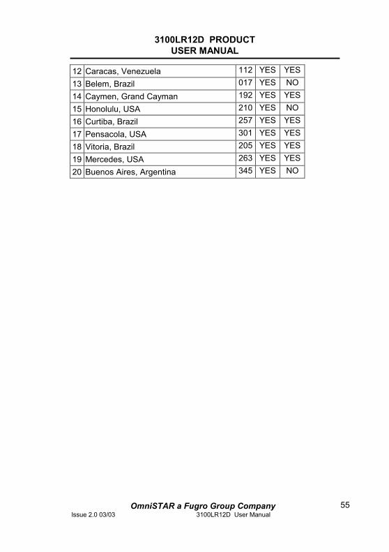
Table 22: Reference stations on AM-Sat
Nr Station ID VBS HP 1 Houston, Texas 100 YES YES2 Cocoa Beach, Florida 120 YES YES3 Long Island, New York 333 YES YES4 Carmen, Mexico 110 YES YES5 Punta Arenas, Chile 210 YES NO 6 Guayaquil, Ecuador 202 YES NO 7 Rio de Janeiro, Brazil 225 YES YES8 St. Johns, Newfoundland 470 YES YES9 Dartmouth, Nova Scotia 440 YES NO
10 Recife, Brazil 075 YES NO
11 Port Of Spain, Trinidad 111 YES YES
3100LR12D PRODUCT USER MANUAL
OmniSTAR a Fugro Group CompanyIssue 2.0 03/03 3100LR12D User Manual
55
12 Caracas, Venezuela 112 YES YES
13 Belem, Brazil 017 YES NO
14 Caymen, Grand Cayman 192 YES YES
15 Honolulu, USA 210 YES NO
16 Curtiba, Brazil 257 YES YES
17 Pensacola, USA 301 YES YES
18 Vitoria, Brazil 205 YES YES
19 Mercedes, USA 263 YES YES
20 Buenos Aires, Argentina 345 YES NO
3100LR12D PRODUCT USER MANUAL
OmniSTAR a Fugro Group CompanyIssue 2.0 03/03 3100LR12D User Manual
56
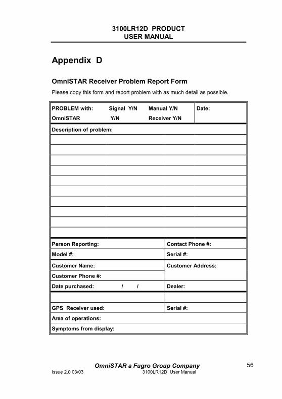
Appendix D
OmniSTAR Receiver Problem Report Form Please copy this form and report problem with as much detail as possible.
PROBLEM with: Signal Y/N Manual Y/N
OmniSTAR Y/N Receiver Y/N
Date:
Description of problem:
Person Reporting: Contact Phone #:
Model #: Serial #:
Customer Name: Customer Address:
Customer Phone #:
Date purchased: / / Dealer:
GPS Receiver used: Serial #:
Area of operations:
Symptoms from display:

3100LR12D PRODUCT USER MANUAL
OmniSTAR a Fugro Group CompanyIssue 2.0 03/03 3100LR12D User Manual
57
Appendix E
OmniSTAR subscription agreement form The next page contains the form, which is necessary to apply for a new OmniSTAR subscription for your 3100LR12D receiver.