Embed Size (px)
Citation preview

7114LR12 Operator’s Manual
Release: May 2004


About this manual This manual has been released by: OmniSTAR BV Dillenburgsingel 69 2263 HW Leidschendam The Netherlands Phone: +31-70-3170900 Fax: +31-70-3170919 Email: [email protected] www.omnistar.nl Manual release date: May, 2004 Manual part number: MAN-7114-00 The information in this manual applies to 7114LR12 receivers with firmware version 1.73 Specifications are subject to change without notice
Copyright Notice
© 2004 OmniSTAR BV. All rights reserved. No part of this manual may be copied, photocopied, reproduced, translated, or reduced to any electronic medium or machine-readable form without prior written consent from OmniSTAR BV.
OmniSTAR 7114LR12 Operator’s Manual
ii
Table of contents
List of figures....................................................................................................... iii List of tables ........................................................................................................ iii OmniSTAR Limited Warranty............................................................................... v 1. Introduction....................................................................................................... 1
1.1 The OmniSTAR system................................................................................ 1 1.2 Subscription ................................................................................................. 2 2.1 Number of visible satellites .......................................................................... 4 2.2 Multipath....................................................................................................... 4 2.3 Position Dilution of Precision (DOP)............................................................. 5 2.4 Satellite elevations ....................................................................................... 5 2.5 GPS mode.................................................................................................... 5 2.6 Differential corrections ................................................................................. 5 2.7 DGPS mode ................................................................................................. 5
3. Installation......................................................................................................... 6 3.1 System parts list ........................................................................................... 6 3.2 Installing the 7114LR12 ............................................................................... 6
3.2.1 Receiver placement .............................................................................. 6 3.2.2 Power considerations............................................................................ 6
3.3 Receiver connections................................................................................... 7 3.3.1 ASCII and TSIP Input............................................................................ 7 3.3.3 1 PPS Output ........................................................................................ 8
3.4 Startup procedure ........................................................................................ 8 3.5 Subscription (re) activation........................................................................... 8
4. Cable and Connectors...................................................................................... 9 4.1 Routing and connecting the 7114LR12 data/power cable.......................... 10 4.2 Connecting to external equipment.............................................................. 11
5 Troubleshooting .............................................................................................. 12 5.1 Increasing GPS accuracy........................................................................... 12 5.2 Intermittent GPS loss ................................................................................. 12 5.3 Power lines and strong magnetic fields...................................................... 12 5.4 Choosing an mounting location.................................................................. 13 5.5 Checking for cable failure........................................................................... 13 5.6 Reducing engine noise............................................................................... 13 5.7 Why satellite DGPS works in some places but not others ......................... 13 5.8 Verifying the unit is outputting NMEA messages ....................................... 13 5.10 Troubleshooting guide.............................................................................. 15 5.11 Contacting OmniSTAR............................................................................. 15
Appendix A - Specifications .............................................................................. 16 Appendix B – List of communication satellites ............................................... 18 APPENDIX C........................................................................................................ 19
List of reference stations .................................................................................. 19 Appendix D - NMEA 0183 ................................................................................... 22
D.1 NMEA introduction..................................................................................... 22 D.2 NMEA 0183 message options ................................................................... 22 D.3 NMEA 0183 message format..................................................................... 23 D.4 NMEA 0183 Message Formats.................................................................. 24
ALM – GPS Almanac Data...................................................................... 24 GBS – GNSS Satellite Fault Detection.................................................... 25
Release March 2003
iii
GGA – GPS Fix Data ............................................................................... 26 GLL – Geographic Position – Latitude/Longitude................................... 27 GRS – GPS Range Residuals ................................................................. 27 GSA – GPS DOP and Active Satellites ................................................... 28 GST – GPS Pseudorange Noise Statistics ............................................. 29 GSV – GPS Satellites in View ................................................................. 30 RMC – Recommended Minimum Specific GPS Data .............................. 31 VTG – Course Over Ground and Ground Speed .................................... 32 ZDA – Time and Date ............................................................................. 33 PTNLDG –DGPS Receiver Status......................................................... 34 PTNL,GGK – Time, Position, Position Type and DOP Values.............. 35 PTNLID –Receiver Identity .................................................................. 35 PTNLSM – RTCM special message ...................................................... 36
Appendix E – OmniSTAR subscription agreement form................................. 37
List of figures Figure 1: Artist impression of the OmniSTAR system ...................................... 2 Figure 2: World coverage map for the OmniSTAR service ............................... 3 Figure 3: EA-SAT coverage area and reference stations .................................. 3 Figure 4: Multipath................................................................................................ 4 Figure 5: 7114LR12 Receiver Bottom View ........................................................ 7 Figure 6: Pinning of the 9 pin sub-D connector on the power/data cable ....... 9 Figure 7: Pins of the 12-pin male (left) and 12-pin female (right) connectors. 9 Figure 8: 7114LR12 Standard data/power cable .............................................. 10 Figure 9: 7114LR12 receiver to a laptop computer.......................................... 11 Figure 10: 7114LR12 receiver to a Pocket PC .................................................. 11 Figure 11: Troubleshooting ............................................................................... 15 Figure 12: Reference stations and coverage area per satellite ...................... 18
List of tables Table 1: 7114LR12 Power/Data cable pin connections ..................................... 9 Table 2: 7114LR12 specifications ..................................................................... 16 Table 3: World-wide satellite frequencies and symbol rates .......................... 18 Table 4: Reference stations on EA-SAT ........................................................... 19 Table 5: Reference stations on AF-SAT............................................................ 19 Table 6: Reference stations on AP-Sat ............................................................. 20 Table 7: Reference stations on AM-Sat ............................................................ 21 Table 8: NMEA 0183 message options ............................................................. 22 Table 9: Description of the ALM message........................................................ 24 Table 10: Description of the GBS message...................................................... 25 Table 11: Description of the GGA message. .................................................... 26 Table 12: Description of the GLL message. ..................................................... 27 Table 13: Description of the GRS message...................................................... 27 Table 14: Description of the GSA message...................................................... 28
OmniSTAR 7114LR12 Operator’s Manual
iv
Table 15: Description of the GST message. ..................................................... 29 Table 16: Description of the GSV message...................................................... 30 Table 17: Description of the RMC message. .................................................... 31 Table 18: Description of the VTG message. ..................................................... 32 Table 19: Description of the ZDA message. ..................................................... 33 Table 20: Description of the PTNLDG message............................................... 34 Table 21: Description of the PTNL,GGK message........................................... 35 Table 22: Description of the PTNLID message. ............................................... 36 Table 23: Description of the PTNLSM message............................................... 36
Release March 2003
v
OmniSTAR Limited Warranty This warranty applies only to normal usage of the product. It does not apply to units or electronic circuit boards, which are defective due to improper installation or handling. Physical damage due to lightning or other electrical discharge and units subjected to fresh or salt-water contamination is not covered. OmniSTAR reserves the right not to warrant the product if, upon request, sufficient proof of recommended installation compliance as laid out in this manual is not provided. No other warranties are expressed or implied. No other warranties exist.
One-Year Limited Hardware Warranty
OmniSTAR reserves the right to repair and/or replace, at its option, any part or parts found to be defective, provided such defects, in their opinion, are due to faulty material or workmanship and are not caused by unauthorised or improper repair or abuse, or normal wear. Purchaser shall be responsible for shipping and insurance of the returned product for repair under this warranty. OmniSTAR will pay shipping and insurance for the product's return to purchaser provided that the product returned proves to be defective under this limited warranty.
OmniSTAR BV and its operating companies world-wide (Fugro NV), warrants this product to be free from defects in workmanship and material for a period of one year from the date of original sale by OmniSTAR or its authorised dealers, to the original purchaser or end user.
OmniSTAR assumes no responsibility for any consequential or incidental losses or damages of any nature with respect to the use of this product.

Release March 2003
1
1. Introduction The Global Positioning System (GPS) is a reliable, continuous, all-weather navigation system, which is operated by the United States Government. At the time of writing, the space segment of GPS includes a constellation of 28 satellites, which orbit the earth at an altitude of approximately 22.000 km. These satellites (Space Vehicles or SV’s) transmit radio signals containing precise satellite time and position information. By receiving four or more of these signals a 3-dimensional position can be computed. Although GPS provides an acceptable level of performance for some users, many applications demand a more reliable and precise position than GPS alone can provide. In such cases Differential GPS (DGPS) must be used. The purpose of DGPS is to minimise the effects of atmospheric and satellite errors on the position determination. In order to achieve this a reference GPS receiver must be installed at a point of known co-ordinates. This receiver uses the radio signals from each of the GPS satellites, which are in view to measure so-called pseudo-ranges to these satellites. Because the exact locations of the satellites and the reference receiver are known, it is then possible to determine the difference between the actual and the expected pseudo-ranges (pseudo-range correction or PRC). In order to provide compatibility for exchanging this correction data, a standard has been developed by the Radio Technical Commission for Maritime Services Special Committee 104. This standard is commonly known as RTCM SC-104. When RTCM version 2.0 correction data from the reference receiver is applied to a nearby GPS receiver, the position accuracy will be substantially better than if stand-alone GPS were to be used.
1.1 The OmniSTAR system
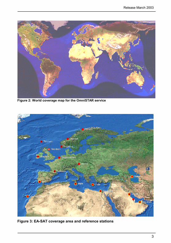
The 7114LR12 is one of several DGPS receivers which have been designed to work with the world-wide OmniSTAR service. The OmniSTAR DGPS system delivers corrections from an array of reference stations, which are located all around the world (see figures 2 and 3 on page 3). The RTCM correction data from these reference stations is provided to OmniSTAR’s two Network Control Centres (NCC) , where the corrections are decoded, checked, and repackaged in a highly efficient format for broadcast. The OmniSTAR data is broadcast over a series of L-band communication satellites. The signal transmitted over each of these satellites contains the corrections from the reference stations in and close to the region in which this satellite can be received. When a receiver with a valid subscription receives data through one of OmniSTAR’s satellite channels it will output a differentially corrected position.
OmniSTAR 7114LR12 Operator’s Manual
2
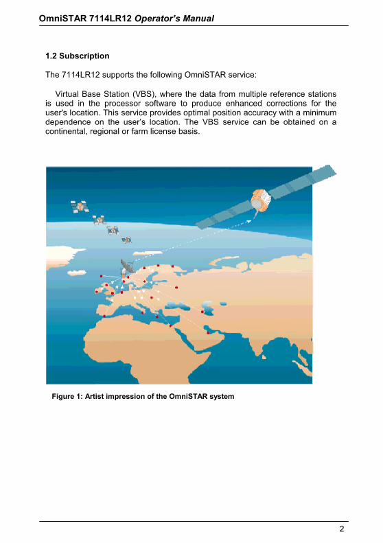
1.2 Subscription The 7114LR12 supports the following OmniSTAR service: • Virtual Base Station (VBS), where the data from multiple reference stations is used in the processor software to produce enhanced corrections for the user's location. This service provides optimal position accuracy with a minimum dependence on the user’s location. The VBS service can be obtained on a continental, regional or farm license basis.
Figure 1: Artist impression of the OmniSTAR system
Release March 2003
3
Figure 2: World coverage map for the OmniSTAR service
Figure 3: EA-SAT coverage area and reference stations
OmniSTAR 7114LR12 Operator’s Manual
4
2. Factors affecting system performance
The 7114LR12 has proven to be a high-quality, sub-meter positioning device. The accuracy that the user can obtain depends on several factors, including: • Number of visible satellites • Multipath • Dilution of Precision (DOP) • Satellite elevations • GPS mode • Differential correction • DGPS mode
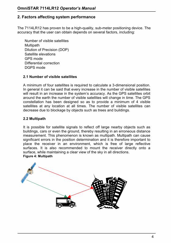
2.1 Number of visible satellites A minimum of four satellites is required to calculate a 3-dimensional position. In general it can be said that every increase in the number of visible satellites will result in an increase in the system’s accuracy. As the GPS satellites orbit around the earth the number of visible satellites will change in time. The GPS constellation has been designed so as to provide a minimum of 4 visible satellites at any location at all times. The number of visible satellites can decrease due to blockage by objects such as trees and buildings. 2.2 Multipath It is possible for satellite signals to reflect off large nearby objects such as buildings, cars or even the ground, thereby resulting in an erroneous distance measurement. This phenomenon is known as multipath. Multipath can cause significant errors in the position determination and it is therefore important to place the receiver in an environment, which is free of large reflective surfaces. It is also recommended to mount the receiver directly onto a surface, while maintaining a clear view of the sky in all directions. Figure 4: Multipath
Release March 2003
5
2.3 Position Dilution of Precision (DOP)
The Position Dilution of Precision (PDOP) is a measure of the satellite geometry. The lower the PDOP value, the more accurate the GPS position will be. By default the 7114LR12 is configured to output position data as long as the Position Dilution of Precision does not exceed 6.
2.4 Satellite elevations
The signal from a satellite, which is low on the horizon, will travel a greater distance through the atmosphere. This results in lower signal strength and a delayed reception, thereby causing erroneous and noisy data. By default the 7114LR12 is configured to ignore any satellites that have an elevation angle lower than 5°.
2.5 GPS mode
The default GPS position mode is Auto 2D/3D. Three-dimensional positions are more accurate than two-dimensional positions, so changing the receiver to Manual 3D prevents 2D positions from being computed.
2.6 Differential corrections
For accurate positioning it is essential that the differential corrections are being received. In order to ensure reception of the OmniSTAR satellite signal it must be prevented that the line of sight towards the satellite is blocked by objects such as trees and buildings. Multipath reflections can cause destructive interference, thereby significantly decreasing the signal strength. It is therefore recommended to mount the 7114LR12 directly onto a surface in a reflection free environment. Although the 7114LR12 has been designed to provide optimal system performance under most circumstances, it is possible, due to the nature of radio communications, that system performance degrades due to local interference sources.
2.7 DGPS mode The DGPS mode default setting is DGPS Auto/On/Off. Selecting DGPS Only, restricting the receiver to only output differential GPS positions, prevents autonomous (non-differential) positions from being computed.
OmniSTAR 7114LR12 Operator’s Manual
6
3. Installation This chapter contains instructions and recommendations for the installation of the 7114LR12.
3.1 System parts list A shipment usually consists of: • 7114LR12 receiver (part nr: REC-7114LR12) • Combined data/power cable • This manual • Magnetic mount • Configuration software
3.2 Installing the 7114LR12 In order to provide for a smooth and successful installation, please observe the following instructions and recommendations.
3.2.1 Receiver placement The 7114LR12 may be mounted using the three M5 threaded inserts in the receiver’s base plate, or the 5/8 threaded insert in the centre of the receiver’s base plate with a pole or the magnetic mount. When selecting a location for installation make sure that:
• The receiver is within reach of power and data cable connections • The cable can not be bent or damaged by external components • The receiver has a clear line of sight towards the L-band
communication satellite. Since these satellites are located above the equator, they are to the South of Europe at an elevation angle of 20°(Oslo) to 45° (Athens).
3.2.2 Power considerations Power can be supplied to the 7114LR12 by connecting 9-32 VDC on the red power wire. The other power wire should be connected to ground. Only supply power after the cable has been connected to the 7114LR12. Never attach or detach a powered cable to/from the unit. The power consumption of the 7114LR12 is 250 mA at 12 V.
Release March 2003
7
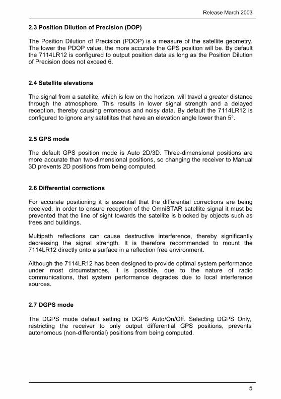
3.3 Receiver connections Figure 5 shows the bottom of the 7114LR12 receiver and its connection port.
Figure 5: 7114LR12 Receiver Bottom View
The connection port can accept power. The 7114LR12 standard power/data cable supplies power and features a data connector for interfacing to an external device. For more information, see Cables and Connectors, page 10.
3.3.1 ASCII and TSIP Input The connection port can be used to input ASCII, TSIP and CAN data from an external device. ASCII data can be received from an external sensor, converted into a NMEA message, and exported to another device. TSIP command packets are used to set and monitor GPS and Satellite DGPS parameters using the included configuration software program.
3.3.2 RTCM, TSIP and NMEA Output The connection port is used to output RTCM, TSIP, NMEA 0183 or CAN messages to an interface device. TSIP is output when communicating with the included configuration software. NMEA is output when exporting GPS position information to an external device, such as a Pocket PC with mapping software.
OmniSTAR 7114LR12 Operator’s Manual
8
CAN is used when communicating over a Can bus system to other connected external devices. 3.3.3 1 PPS Output
The connection port can output a 1 PPS (pulse per second) strobe signal to synchronise the external instruments to the receiver’s internal clock.
3.4 Startup procedure Consider the following guidelines before starting to work with the system: • Normally the receiver software is already set to the user’s specific requirements • Make sure that the 7114LR12 has a clear line of sight to the communication
satellite • Connect the 9 pin sub-D connector to a PC (or other logging device), which has
been set to communicate using 9600,8,N,1 • Connect the power cable to an appropriate power supply (9 to 32 VDC) which
has been turned off • Turn on the power supply When the unit is used for the first time, has not been used for a long period of time, or has been moved a long distance it may take up to 12.5 minutes to start outputting NMEA messages. The outputting of differentially corrected NMEA may take up to 45 minutes under these circumstances.
3.5 Subscription (re) activation
If the OmniSTAR subscription on your 7114LR12 has not been activated yet, will expire soon or has been expired already, a new subscription can be sent over the satellite link. The procedure for obtaining a new subscription is: • Fill in the OmniSTAR subscription agreement form (see Appendix E) • Fax the form to OmniSTAR BV at +31-70-3170919 • At the agreed time of activation make sure your receiver is outside and in a
place where it will be able to receive signals from the communication satellite • Have the receiver switched on at the time of activation At the time of activation a series of commands containing the new expiry date and other subscription information will be sent over the satellite link to your 7114LR12 receiver. If your receiver does not start outputting differential position data within 45 minutes after the activation time, please contact OmniSTAR by phone at +31-70-3170900.
Release March 2003
9
4. Cable and Connectors
5 4 3 2 1
9 8 7 6
Data Port
DB9 Female
Pin#123456789
SignalN/ARXDTXDEVEGNDN/AN/AN/AN/A
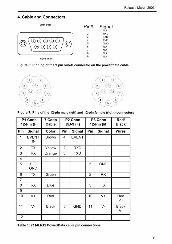
Figure 6: Pinning of the 9 pin sub-D connector on the power/data cable
Figure 7: Pins of the 12-pin male (left) and 12-pin female (right) connectors
P1 Conn 12-Pin (F)
7 Conn Cable
P2 Conn DB-9 (F)
P3 Conn 12-Pin (M)
Red/ Black
Pin Signal Color Pin Signal Pin Signal Wires 1 EVENT
IN Brown 4 EVENT
2 TX Yellow 2 RXD 3 RX Orange 3 TXD 45 SIG
GND 5 GND
6 TX Green 2 RX 78 RX Blue 3 TX 9
10 V+ Red 10 V+ Red V+
11 V- Black 5 GND 11 V- Black V-
12
Table 1: 7114LR12 Power/Data cable pin connections
OmniSTAR 7114LR12 Operator’s Manual
10
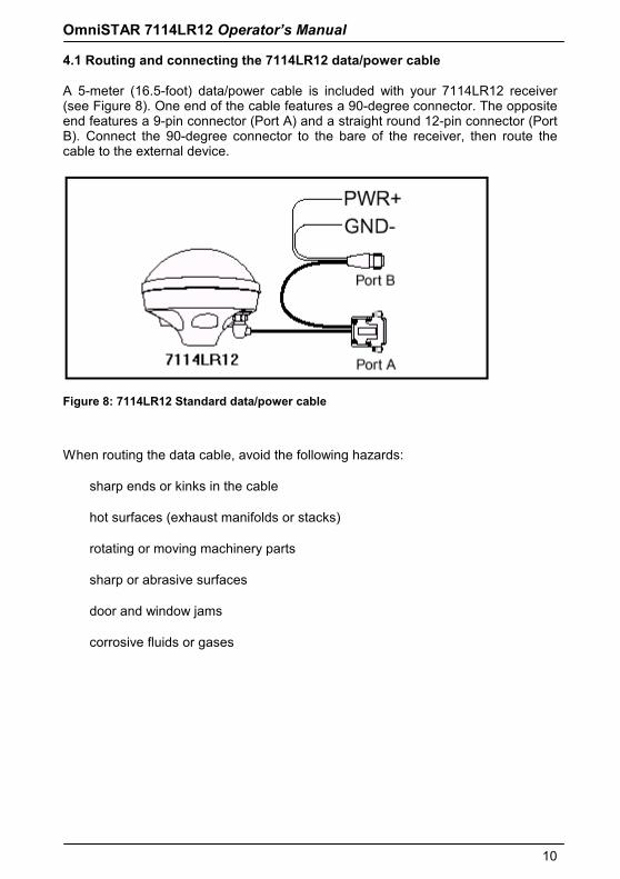
4.1 Routing and connecting the 7114LR12 data/power cable A 5-meter (16.5-foot) data/power cable is included with your 7114LR12 receiver (see Figure 8). One end of the cable features a 90-degree connector. The opposite end features a 9-pin connector (Port A) and a straight round 12-pin connector (Port B). Connect the 90-degree connector to the bare of the receiver, then route the cable to the external device.
Figure 8: 7114LR12 Standard data/power cable
When routing the data cable, avoid the following hazards: • sharp ends or kinks in the cable • hot surfaces (exhaust manifolds or stacks) • rotating or moving machinery parts • sharp or abrasive surfaces • door and window jams • corrosive fluids or gases
Release March 2003
11
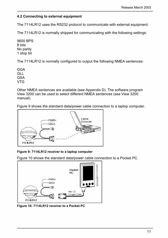
4.2 Connecting to external equipment The 7114LR12 uses the RS232 protocol to communicate with external equipment. The 7114LR12 is normally shipped for communicating with the following settings: 9600 BPS 8 bits No parity 1 stop bit The 7114LR12 is normally configured to output the following NMEA sentences: GGA GLL GSA VTG Other NMEA sentences are available (see Appendix D). The software program View 3200 can be used to select different NMEA sentences (see View 3200 manual). Figure 9 shows the standard data/power cable connection to a laptop computer.
Figure 9: 7114LR12 receiver to a laptop computer
Figure 10 shows the standard data/power cable connection to a Pocket PC.
Figure 10: 7114LR12 receiver to a Pocket PC
OmniSTAR 7114LR12 Operator’s Manual
12
5 Troubleshooting Troubleshooting This chapter covers frequently asked questions and troubleshooting techniques for the 7114LR12 receiver. OmniSTAR recommends you to read through this chapter before calling technical support.
5.1 Increasing GPS accuracy The 7114LR12 receiver always gives the most accurate position under the current GPS, satellite differential operating conditions. By manipulating various GPS masks, some satellite configurations are locked out, preventing less accurate positions from being computed. However, these changes can prevent positions from being output. If your GPS application can tolerate occasional outages, then more accuracy is possible by changing the various GPS receiver parameters from their default values. There are many GPS receiver parameters that affect accuracy. For more information see page 4, Factors affecting system performance.
5.2 Intermittent GPS loss
When GPS lock is intermittent, the power/data cable may have a loose connection. Check that all connections are secured properly. Water may enter the cable connection and cause intermittent loss of GPS. Disconnect the cable and let the connection dry. Reconnect the cable. If the receiver is connected properly, make sure that it is mounted on the highest point of the vehicle, so that no GPS signals are blocked. Depending on the orientation of the vehicle, the satellites and the possible obstruction, one or more satellites may be blocked. Sometimes blocking shows up when traveling one direction, but not while traveling other directions. If the receiver seems fine, check the configuration masks. If the PDOP or SNR Masks are set to extreme levels, the receiver could possibly ignore valid satellite data. The default SNR Mask is 6. The default PDOP Mask is 6.
5.3 Power lines and strong magnetic fields
In Europe, the energy from power lines is 50 Hz. The harmonic energy falls off rapidly as the frequency increases. Thus, power lines have very little effect on the GPS & Satellite Differential Signals.
Strong magnetic fields have no effect on GPS & Satellite Differential signals. Some computers and other electric equipment radiate electromagnetic energy that can interfere with a GPS receiver. If you suspect interference from a local magnetic field, move the receiver away from, or turn off the suspect electronics while observing the GPS receiver’s number of satellites being tracked or satellite’s signal-to-noise ratio.
Release March 2003
13
5.4 Choosing an mounting location The receiver must be mounted so that it has a clear view of the sky, on the center line of the vehicle, away from any sources of interference like electric motors. See Installation, page 6.
5.5 Checking for cable failure To check a cable for a short, use an ohmmeter. The resistance of a good cable between connector pins at each end of the cable, is zero. If the cable checks out fine, but you are confident it is the cable causing the errors, swap out the cable with another known working cable (if possible). If the cable is defective, contact OmniSTAR for a replacement.
5.6 Reducing engine noise An unshielded ignition system can radiate enough noise to block reception of the OmniSTAR signal. To solve this problem, use resistor spark plug wires. Sometimes an alternator generates noise that interferes with the signal. Use bypass capacitors, commonly available in automotive stores for cleaning up interference to CB and other radios. If the problem persists, engine components can be shielded with aluminum foil. Before purchasing new engine parts, make sure that there is not a PC computer or power source near the 7114LR12 receiver. Some PCs and their power sources generate noise that is disruptive to the GPS & satellite DGPS signals.
5.7 Why satellite DGPS works in some places but not others Local canopy cover in the direction of the differential satellite can reduce the correction signal strength to unusable levels. Wet canopy reduces signals even more. The same local environmental factors that affect GPS signals, such as radar sets, microwave transmitters, and the like can interfere with the differential satellite signals. 5.8 Verifying the unit is outputting NMEA messages Connect the 7114LR12 receiver to a PC with the Standard Data/Power Cable and use Windows 95/98’s HyperTerminal or any other terminal program to view the NMEA messages input through the computer’s serial port. The default NMEA parameters are 9600-N-8-1.
OmniSTAR 7114LR12 Operator’s Manual
14
5.9 Losing configuration settings when the receiver is powered off The 7114LR12 receiver configuration parameter settings are stored in battery-backed RAM (random access memory). The Lithium battery has a 10-year life span. You can assume the Lithium battery has failed when the receiver no longer retains configuration parameter setting changes. Note – The receiver can continue to use the default configuration parameters, but does not retain any custom changes to the default settings after it is powered off. Contact OmniSTAR Technical Support Service at +31-70-3170900 to arrange for replacement of Lithium batteries.
Release March 2003
15
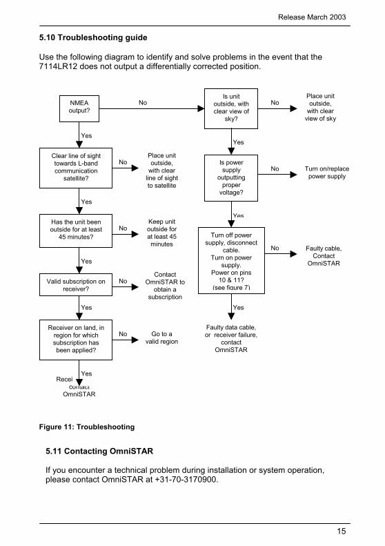
5.10 Troubleshooting guide Use the following diagram to identify and solve problems in the event that the 7114LR12 does not output a differentially corrected position.
Figure 11: Troubleshooting
5.11 Contacting OmniSTAR If you encounter a technical problem during installation or system operation, please contact OmniSTAR at +31-70-3170900.
Receiver failure, contact
OmniSTAR
No
No
Yes
Yes
Yes
No No NMEA output?
Is unit outside, with clear view of
sky?
Place unit outside,
with clear view of sky
Is power supply
outputting proper
voltage?
No Turn on/replace power supply
Turn off power supply, disconnect
cable. Turn on power
supply. Power on pins
10 & 11? (see figure 7)
Faulty cable,Contact
OmniSTAR
Faulty data cable, or receiver failure,
contact OmniSTAR
Yes
Clear line of sight towards L-band communication
satellite?
Place unit outside,
with clear line of sight to satellite
No
Yes
Has the unit been outside for at least
45 minutes?
Keep unit outside for at least 45 minutes
No
Yes
Contact OmniSTAR to
obtain a subscription
No
Yes
Receiver on land, in region for which subscription has been applied?
Go to a valid region
Yes
Valid subscription on receiver?
OmniSTAR 7114LR12 Operator’s Manual
16
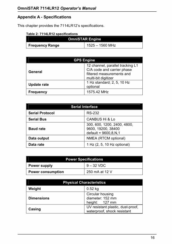
Appendix A - Specifications This chapter provides the 7114LR12’s specifications.
Table 2: 7114LR12 specifications OmniSTAR Engine
Frequency Range 1525 – 1560 MHz
GPS Engine
General 12 channel, parallel tracking L1 C/A code and carrier phase filtered measurements and multi-bit digitizer
Update rate 1 Hz standard; 2, 5, 10 Hz optional
Frequency 1575.42 MHz
Serial Interface Serial Protocol RS-232
Serial Bus CANBUS Hi & Lo
Baud rate 300, 600, 1200, 2400, 4800, 9600, 19200, 38400 default = 9600,8,N,1
Data output NMEA (RTCM optional)
Data rate 1 Hz (2, 5, 10 Hz optional)
Power Specifications Power supply 9 – 32 VDC
Power consumption 250 mA at 12 V
Physical Characteristics Weight 0.52 kg
Dimensions Circular housing diameter: 152 mm height: 127 mm
Casing UV resistant plastic, dust-proof, waterproof, shock resistant

Release March 2003
17
Environmental Specifications Operating Temperature -30°C to 60°CStorage Temperature -40°C to 80°C
Humidity 100% condensing, unit fully sealed
Approvals Compliance FCC Class B, CE, EP 455
OmniSTAR 7114LR12 Operator’s Manual
18
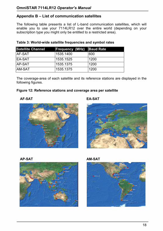
Appendix B – List of communication satellites The following table presents a list of L-band communication satellites, which will enable you to use your 7114LR12 over the entire world (depending on your subscription type you might only be entitled to a restricted area).
Table 3: World-wide satellite frequencies and symbol rates
Satellite Channel Frequency (MHz) Baud Rate AF-SAT 1535.1400 600 EA-SAT 1535.1525 1200 AP-SAT 1535.1375 1200 AM-SAT 1535.1375 1200
The coverage-area of each satellite and its reference stations are displayed in the following figures. Figure 12: Reference stations and coverage area per satellite
AF-SAT EA-SAT
AP-SAT AM-SAT
Release March 2003
19
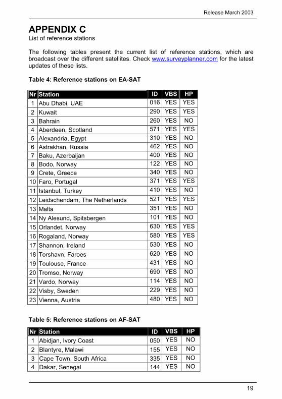
APPENDIX C List of reference stations The following tables present the current list of reference stations, which are broadcast over the different satellites. Check www.surveyplanner.com for the latest updates of these lists. Table 4: Reference stations on EA-SAT
Nr Station ID VBS HP 1 Abu Dhabi, UAE 016 YES YES
2 Kuwait 290 YES YES3 Bahrain 260 YES NO 4 Aberdeen, Scotland 571 YES YES5 Alexandria, Egypt 310 YES NO 6 Astrakhan, Russia 462 YES NO 7 Baku, Azerbaijan 400 YES NO 8 Bodo, Norway 122 YES NO 9 Crete, Greece 340 YES NO
10 Faro, Portugal 371 YES YES
11 Istanbul, Turkey 410 YES NO
12 Leidschendam, The Netherlands 521 YES YES
13 Malta 351 YES NO
14 Ny Alesund, Spitsbergen 101 YES NO
15 Orlandet, Norway 630 YES YES
16 Rogaland, Norway 580 YES YES
17 Shannon, Ireland 530 YES NO
18 Torshavn, Faroes 620 YES NO
19 Toulouse, France 431 YES NO
20 Tromso, Norway 690 YES NO
21 Vardo, Norway 114 YES NO
22 Visby, Sweden 229 YES NO
23 Vienna, Austria 480 YES NO
Table 5: Reference stations on AF-SAT
Nr Station ID VBS HP 1 Abidjan, Ivory Coast 050 YES NO
2 Blantyre, Malawi 155 YES NO 3 Cape Town, South Africa 335 YES NO 4 Dakar, Senegal 144 YES NO
OmniSTAR 7114LR12 Operator’s Manual
20
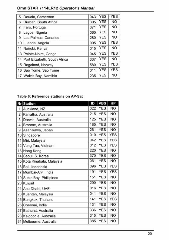
5 Douala, Cameroon 043 YES YES6 Durban, South Africa 305 YES NO 7 Faro, Portugal 371 YES NO 8 Lagos, Nigeria 060 YES NO 9 Las Palmas, Canaries 280 YES NO
10 Luanda, Angola 095 YES YES
11 Nairobi, Kenya 015 YES NO
13 Pointe-Noire, Congo 045 YES YES
14 Port Elizabeth, South Africa 337 YES NO
15 Rogaland, Norway 580 YES YES
16 Sao Tome, Sao Tome 011 YES YES
17 Walvis Bay, Namibia 235 YES NO
Table 6: Reference stations on AP-Sat
Nr Station ID VBS HP 1 Auckland, NZ 022 YES NO
2 Karratha, Australia 215 YES NO 3 Darwin, Australia 125 YES NO 4 Broome, Australia 185 YES NO 9 Asahikawa, Japan 261 YES NO
10 Singapore 010 YES YES11 Miri, Malaysia 042 YES YES12 Vung Tua, Vietnam 012 YES YES13 Hong Kong 220 YES NO 14 Seoul, S. Korea 370 YES NO 15 Kota Kinabalu, Malaysia 061 YES NO
16 Bali, Indonesia 096 YES YES
17 Mumbai-Arvi, India 191 YES YES
19 Subic Bay, Phillipines 151 YES NO
20 Kuwait 290 YES NO
21 Abu Dhabi, UAE 016 YES NO
23 Kuantan, Malaysia 041 YES NO
25 Bangkok, Thailand 141 YES YES
26 Chennai, India 131 YES NO
27 Bathurst, Australia 336 YES NO
28 Kalgoorlie, Australia 315 YES NO
31 Melbourne, Australia 385 YES NO
Release March 2003
21
32 Okinawa, Japan 261 YES NO
33 Platong, Thailand 018 YES NO
34 Sakhalin, Russia 510 YES NO
35 Bahrain, Bahrain 260 YES NO
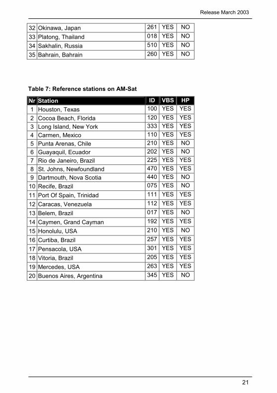
Table 7: Reference stations on AM-Sat
Nr Station ID VBS HP 1 Houston, Texas 100 YES YES2 Cocoa Beach, Florida 120 YES YES3 Long Island, New York 333 YES YES4 Carmen, Mexico 110 YES YES5 Punta Arenas, Chile 210 YES NO 6 Guayaquil, Ecuador 202 YES NO 7 Rio de Janeiro, Brazil 225 YES YES8 St. Johns, Newfoundland 470 YES YES9 Dartmouth, Nova Scotia 440 YES NO
10 Recife, Brazil 075 YES NO
11 Port Of Spain, Trinidad 111 YES YES
12 Caracas, Venezuela 112 YES YES
13 Belem, Brazil 017 YES NO
14 Caymen, Grand Cayman 192 YES YES
15 Honolulu, USA 210 YES NO
16 Curtiba, Brazil 257 YES YES
17 Pensacola, USA 301 YES YES
18 Vitoria, Brazil 205 YES YES
19 Mercedes, USA 263 YES YES
20 Buenos Aires, Argentina 345 YES NO
OmniSTAR 7114LR12 Operator’s Manual
22
Appendix D - NMEA 0183 D.1 NMEA introduction NMEA 0183 is an interface protocol created by the National Marine Electronics Association. The latest release of NMEA 0183 is Version 2.2. This protocol was originally established to allow marine navigation equipment to share information. NMEA 0183 is a simple, yet comprehensive ASCII protocol, which defines both the communication interface and the data format.
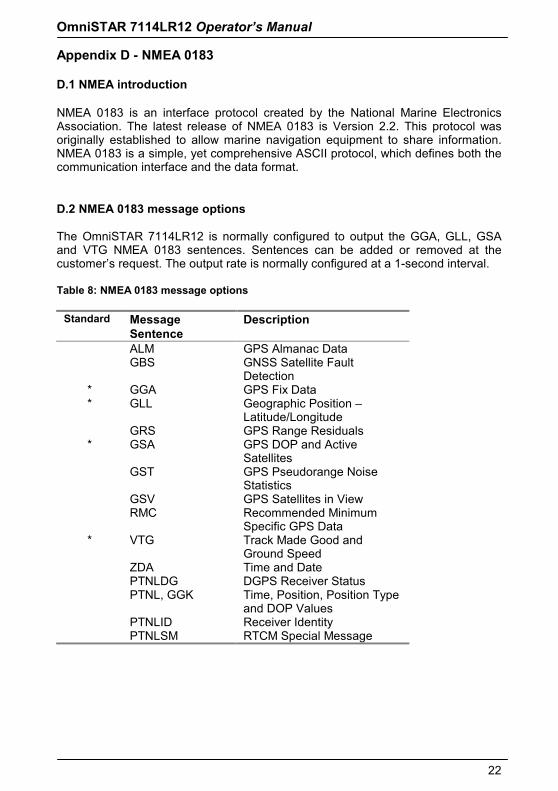
D.2 NMEA 0183 message options The OmniSTAR 7114LR12 is normally configured to output the GGA, GLL, GSA and VTG NMEA 0183 sentences. Sentences can be added or removed at the customer’s request. The output rate is normally configured at a 1-second interval. Table 8: NMEA 0183 message options
Standard Message Sentence
Description
ALM GPS Almanac Data GBS GNSS Satellite Fault
Detection * GGA GPS Fix Data * GLL Geographic Position –
Latitude/Longitude GRS GPS Range Residuals * GSA GPS DOP and Active
Satellites GST GPS Pseudorange Noise
Statistics GSV GPS Satellites in View RMC Recommended Minimum
Specific GPS Data * VTG Track Made Good and
Ground Speed ZDA Time and Date PTNLDG DGPS Receiver Status PTNL, GGK Time, Position, Position Type
and DOP Values PTNLID Receiver Identity PTNLSM RTCM Special Message
Release March 2003
23
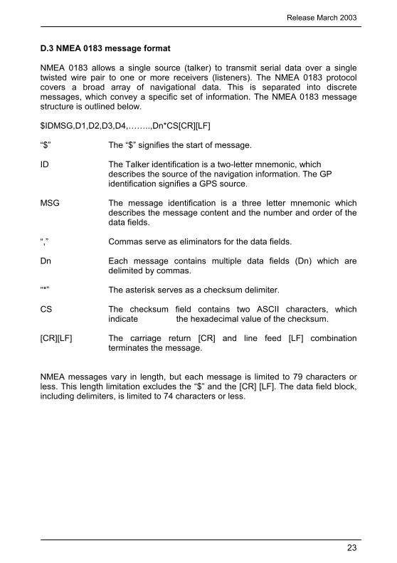
D.3 NMEA 0183 message format
NMEA 0183 allows a single source (talker) to transmit serial data over a single twisted wire pair to one or more receivers (listeners). The NMEA 0183 protocol covers a broad array of navigational data. This is separated into discrete messages, which convey a specific set of information. The NMEA 0183 message structure is outlined below. $IDMSG,D1,D2,D3,D4,……..,Dn*CS[CR][LF] “$” The “$” signifies the start of message. ID The Talker identification is a two-letter mnemonic, which
describes the source of the navigation information. The GP identification signifies a GPS source.
MSG The message identification is a three letter mnemonic which
describes the message content and the number and order of the data fields.
“,” Commas serve as eliminators for the data fields. Dn Each message contains multiple data fields (Dn) which are
delimited by commas. “*” The asterisk serves as a checksum delimiter. CS The checksum field contains two ASCII characters, which
indicate the hexadecimal value of the checksum. [CR][LF] The carriage return [CR] and line feed [LF] combination
terminates the message.
NMEA messages vary in length, but each message is limited to 79 characters or less. This length limitation excludes the “$” and the [CR] [LF]. The data field block, including delimiters, is limited to 74 characters or less.
OmniSTAR 7114LR12 Operator’s Manual
24
D.4 NMEA 0183 Message Formats
In this section each message is described in more detail.
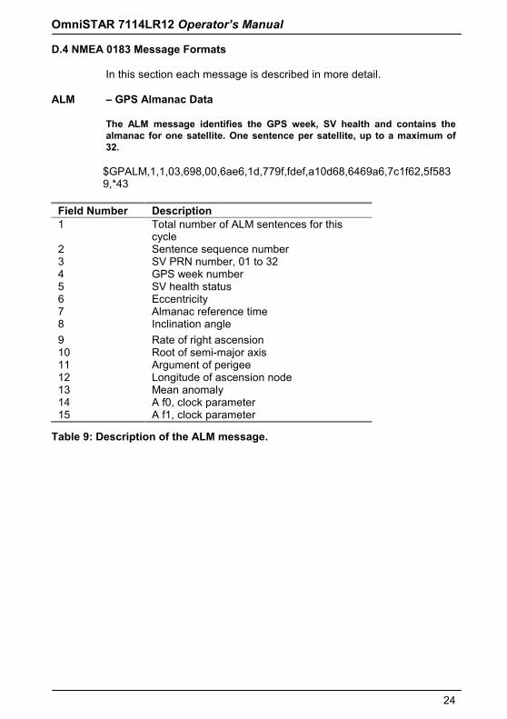
ALM – GPS Almanac Data
The ALM message identifies the GPS week, SV health and contains the almanac for one satellite. One sentence per satellite, up to a maximum of 32.
$GPALM,1,1,03,698,00,6ae6,1d,779f,fdef,a10d68,6469a6,7c1f62,5f5839,*43
Field Number Description 1 Total number of ALM sentences for this
cycle 2 Sentence sequence number 3 SV PRN number, 01 to 32 4 GPS week number 5 SV health status 6 Eccentricity 7 Almanac reference time 8 Inclination angle 9 Rate of right ascension 10 Root of semi-major axis 11 Argument of perigee 12 Longitude of ascension node 13 Mean anomaly 14 A f0, clock parameter 15 A f1, clock parameter
Table 9: Description of the ALM message.
Release March 2003
25
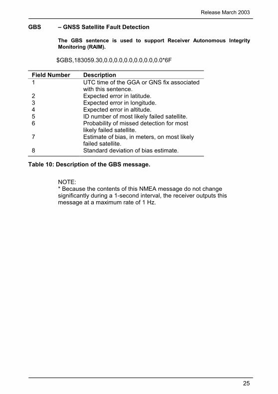
GBS – GNSS Satellite Fault Detection
The GBS sentence is used to support Receiver Autonomous Integrity Monitoring (RAIM).
$GBS,183059.30,0.0,0.0,0.0,0.0,0.0,0.0*6F
Field Number Description 1 UTC time of the GGA or GNS fix associated
with this sentence. 2 Expected error in latitude. 3 Expected error in longitude. 4 Expected error in altitude. 5 ID number of most likely failed satellite. 6 Probability of missed detection for most
likely failed satellite. 7 Estimate of bias, in meters, on most likely
failed satellite. 8 Standard deviation of bias estimate.
Table 10: Description of the GBS message.
NOTE: * Because the contents of this NMEA message do not change significantly during a 1-second interval, the receiver outputs this message at a maximum rate of 1 Hz.
OmniSTAR 7114LR12 Operator’s Manual
26
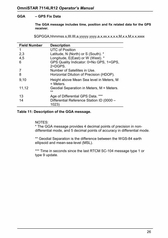
GGA – GPS Fix Data
The GGA message includes time, position and fix related data for the GPS receiver.
$GPGGA,hhmmss.s,llll.llll,a,yyyyy.yyyy,a,x,xx,x.x,x.x,M,x.x,M,x.x,xxxx
Field Number Description 1 UTC of Position 2,3 Latitude, N (North) or S (South). * 4,5 Longitude, E(East) or W (West). * 6 GPS Quality Indicator: 0=No GPS, 1=GPS,
2=DGPS. 7 Number of Satellites in Use. 8 Horizontal Dilution of Precision (HDOP). 9,10 Height above Mean Sea level in Meters, M
= Meters. 11,12 Geodial Separation in Meters, M = Meters.
** 13 Age of Differential GPS Data. *** 14 Differential Reference Station ID (0000 –
1023)
Table 11: Description of the GGA message.
NOTES: * The GGA message provides 4 decimal points of precision in non-differential mode, and 5 decimal points of accuracy in differential mode. ** Geodial Separation is the difference between the WGS-84 earth ellipsoid and mean-sea-level (MSL). *** Time in seconds since the last RTCM SC-104 message type 1 or type 9 update.
Release March 2003
27
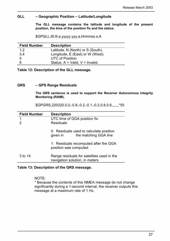
GLL – Geographic Position – Latitude/Longitude The GLL message contains the latitude and longitude of the present position, the time of the position fix and the status.
$GPGLL,llll.lll,a,yyyyy.yyy,a,hhmmss.s,A
Field Number Description 1,2 Latitude, N (North) or S (South). 3,4 Longitude, E (East) or W (West). 5 UTC of Position. 6 Status: A = Valid, V = Invalid.
Table 12: Description of the GLL message.
GRS – GPS Range Residuals The GRS sentence is used to support the Receiver Autonomous Integrity Monitoring (RAIM).
$GPGRS,220320.0,0,-0.8,-0.2,-0.1,-0.2,0.8,0.6,,,,,,,*55
Field Number Description 1 UTC time of GGA position fix 2 Residuals
0: Residuals used to calculate position given in the matching GGA line 1: Residuals recomputed after the GGA position was computed
3 to 14 Range residuals for satellites used in the navigation solution, in meters
Table 13: Description of the GRS message.
NOTE: * Because the contents of this NMEA message do not change significantly during a 1-second interval, the receiver outputs this message at a maximum rate of 1 Hz.
OmniSTAR 7114LR12 Operator’s Manual
28
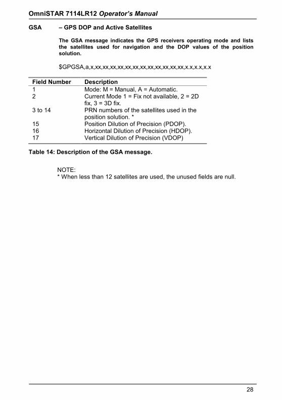
GSA – GPS DOP and Active Satellites The GSA message indicates the GPS receivers operating mode and lists the satellites used for navigation and the DOP values of the position solution.
$GPGSA,a,x,xx,xx,xx,xx,xx,xx,xx,xx,xx,xx,xx,xx,x.x,x.x,x.x
Field Number Description 1 Mode: M = Manual, A = Automatic. 2 Current Mode 1 = Fix not available, 2 = 2D
fix, 3 = 3D fix. 3 to 14 PRN numbers of the satellites used in the
position solution. * 15 Position Dilution of Precision (PDOP). 16 Horizontal Dilution of Precision (HDOP). 17 Vertical Dilution of Precision (VDOP)
Table 14: Description of the GSA message.
NOTE: * When less than 12 satellites are used, the unused fields are null.
Release March 2003
29
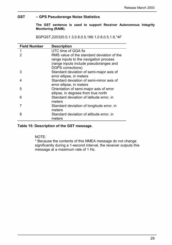
GST – GPS Pseudorange Noise Statistics The GST sentence is used to support Receiver Autonomous Integrity Monitoring (RAIM).
$GPGST,220320.0,1.3,0.8,0.5,166.1,0.8,0.5,1.6,*4F
Field Number Description 1 UTC time of GGA fix 2 RMS value of the standard deviation of the
range inputs to the navigation process (range inputs include pseudoranges and DGPS corrections)
3 Standard deviation of semi-major axis of error ellipse, in meters
4 Standard deviation of semi-minor axis of error ellipse, in meters
5 Orientation of semi-major axis of error ellipse, in degrees from true north
6 Standard deviation of latitude error, in meters
7 Standard deviation of longitude error, in meters
8 Standard deviation of altitude error, in meters
Table 15: Description of the GST message.
NOTE: * Because the contents of this NMEA message do not change significantly during a 1-second interval, the receiver outputs this message at a maximum rate of 1 Hz.
OmniSTAR 7114LR12 Operator’s Manual
30
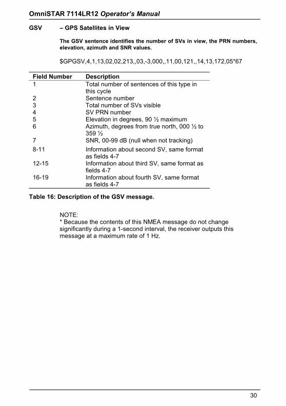
GSV – GPS Satellites in View The GSV sentence identifies the number of SVs in view, the PRN numbers, elevation, azimuth and SNR values.
$GPGSV,4,1,13,02,02,213,,03,-3,000,,11,00,121,,14,13,172,05*67
Field Number Description 1 Total number of sentences of this type in
this cycle 2 Sentence number 3 Total number of SVs visible 4 SV PRN number 5 Elevation in degrees, 90 ½ maximum 6 Azimuth, degrees from true north, 000 ½ to
359 ½ 7 SNR, 00-99 dB (null when not tracking) 8-11 Information about second SV, same format
as fields 4-7 12-15 Information about third SV, same format as
fields 4-7 16-19 Information about fourth SV, same format
as fields 4-7
Table 16: Description of the GSV message.
NOTE: * Because the contents of this NMEA message do not change significantly during a 1-second interval, the receiver outputs this message at a maximum rate of 1 Hz.
Release March 2003
31
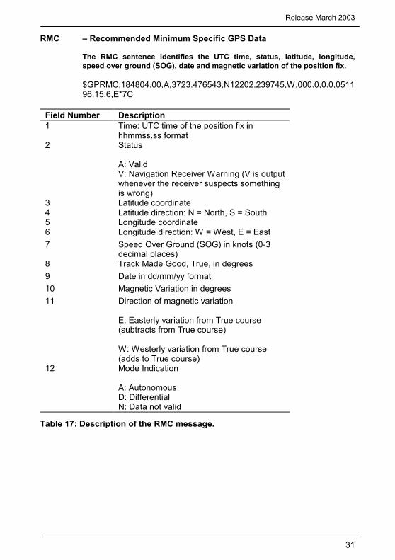
RMC – Recommended Minimum Specific GPS Data The RMC sentence identifies the UTC time, status, latitude, longitude, speed over ground (SOG), date and magnetic variation of the position fix.
$GPRMC,184804.00,A,3723.476543,N12202.239745,W,000.0,0.0,051196,15.6,E*7C
Field Number Description 1 Time: UTC time of the position fix in
hhmmss.ss format 2 Status
A: Valid V: Navigation Receiver Warning (V is output whenever the receiver suspects something is wrong)
3 Latitude coordinate 4 Latitude direction: N = North, S = South 5 Longitude coordinate 6 Longitude direction: W = West, E = East 7 Speed Over Ground (SOG) in knots (0-3
decimal places) 8 Track Made Good, True, in degrees 9 Date in dd/mm/yy format 10 Magnetic Variation in degrees 11 Direction of magnetic variation
E: Easterly variation from True course (subtracts from True course) W: Westerly variation from True course (adds to True course)
12 Mode Indication A: Autonomous D: Differential N: Data not valid
Table 17: Description of the RMC message.
OmniSTAR 7114LR12 Operator’s Manual
32
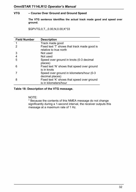
VTG – Course Over Ground and Ground Speed The VTG sentence identifies the actual track made good and speed over ground.
$GPVTG,0,T,,,0.00,N,0.00,K*33
Field Number Description 1 Track made good 2 Fixed text ‘T’ shows that track made good is
relative to true north 3 Not used 4 Not used 5 Speed over ground in knots (0-3 decimal
places) 6 Fixed text ‘N’ shows that speed over ground
is in knots 7 Speed over ground in kilometers/hour (0-3
decimal places) 8 Fixed text ‘K’ shows that speed over ground
is in kilometers/hour
Table 18: Description of the VTG message.
NOTE: * Because the contents of this NMEA message do not change significantly during a 1-second interval, the receiver outputs this message at a maximum rate of 1 Hz.
Release March 2003
33
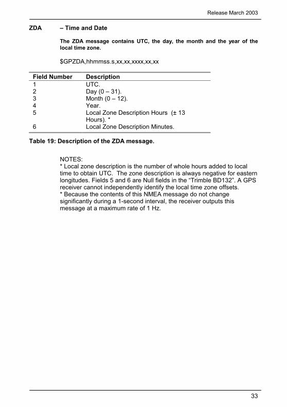
ZDA – Time and Date The ZDA message contains UTC, the day, the month and the year of the local time zone.
$GPZDA,hhmmss.s,xx,xx,xxxx,xx,xx
Field Number Description 1 UTC. 2 Day (0 – 31). 3 Month (0 – 12). 4 Year. 5 Local Zone Description Hours (± 13
Hours). * 6 Local Zone Description Minutes.
Table 19: Description of the ZDA message.
NOTES: * Local zone description is the number of whole hours added to local time to obtain UTC. The zone description is always negative for eastern longitudes. Fields 5 and 6 are Null fields in the “Trimble BD132”. A GPS receiver cannot independently identify the local time zone offsets. * Because the contents of this NMEA message do not change significantly during a 1-second interval, the receiver outputs this message at a maximum rate of 1 Hz.
OmniSTAR 7114LR12 Operator’s Manual
34
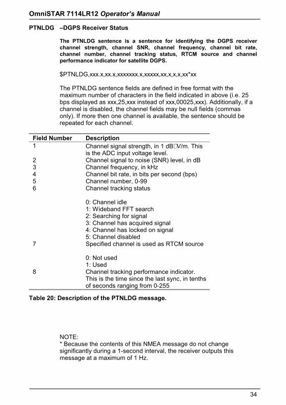
PTNLDG –DGPS Receiver Status The PTNLDG sentence is a sentence for identifying the DGPS receiver channel strength, channel SNR, channel frequency, channel bit rate, channel number, channel tracking status, RTCM source and channel performance indicator for satellite DGPS.
$PTNLDG,xxx.x,xx.x,xxxxxxx.x,xxxxx,xx,x,x,x,xx*xx The PTNLDG sentence fields are defined in free format with the maximum number of characters in the field indicated in above (i.e. 25 bps displayed as xxx,25,xxx instead of xxx,00025,xxx). Additionally, if a channel is disabled, the channel fields may be null fields (commas only). If more then one channel is available, the sentence should be repeated for each channel.
Field Number Description 1 Channel signal strength, in 1 dBµV/m. This
is the ADC input voltage level. 2 Channel signal to noise (SNR) level, in dB 3 Channel frequency, in kHz 4 Channel bit rate, in bits per second (bps) 5 Channel number, 0-99 6 Channel tracking status
0: Channel idle 1: Wideband FFT search 2: Searching for signal 3: Channel has acquired signal 4: Channel has locked on signal 5: Channel disabled
7 Specified channel is used as RTCM source 0: Not used 1: Used
8 Channel tracking performance indicator. This is the time since the last sync, in tenths of seconds ranging from 0-255
Table 20: Description of the PTNLDG message.
NOTE: * Because the contents of this NMEA message do not change significantly during a 1-second interval, the receiver outputs this message at a maximum of 1 Hz.
Release March 2003
35
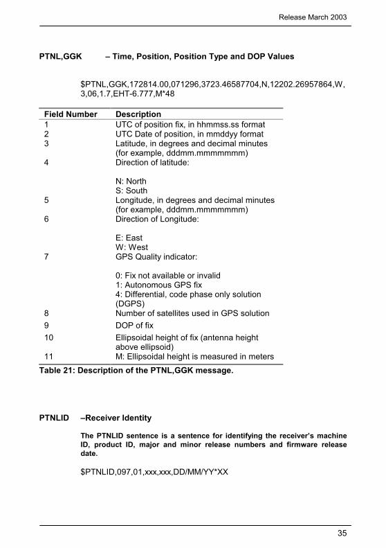
PTNL,GGK – Time, Position, Position Type and DOP Values
$PTNL,GGK,172814.00,071296,3723.46587704,N,12202.26957864,W,3,06,1.7,EHT-6.777,M*48
Field Number Description 1 UTC of position fix, in hhmmss.ss format 2 UTC Date of position, in mmddyy format 3 Latitude, in degrees and decimal minutes
(for example, dddmm.mmmmmmm) 4 Direction of latitude:
N: North S: South
5 Longitude, in degrees and decimal minutes (for example, dddmm.mmmmmmm)
6 Direction of Longitude: E: East W: West
7 GPS Quality indicator: 0: Fix not available or invalid 1: Autonomous GPS fix 4: Differential, code phase only solution (DGPS)
8 Number of satellites used in GPS solution 9 DOP of fix 10 Ellipsoidal height of fix (antenna height
above ellipsoid) 11 M: Ellipsoidal height is measured in meters
Table 21: Description of the PTNL,GGK message.
PTNLID –Receiver Identity The PTNLID sentence is a sentence for identifying the receiver’s machine ID, product ID, major and minor release numbers and firmware release date.
$PTNLID,097,01,xxx,xxx,DD/MM/YY*XX
OmniSTAR 7114LR12 Operator’s Manual
36
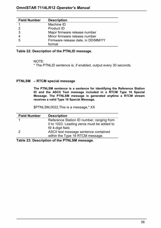
Field Number Description 1 Machine ID 2 Product ID 3 Major firmware release number 4 Minor firmware release number 5 Firmware release date, in DD/MM/YY
format
Table 22: Description of the PTNLID message.
NOTE: * The PTNLID sentence is, if enabled, output every 30 seconds.
PTNLSM – RTCM special message The PTNLSM sentence is a sentence for identifying the Reference Station ID and the ASCII Text message included in a RTCM Type 16 Special Message. The PTNLSM message is generated anytime a RTCM stream receives a valid Type 16 Special Message.
$PTNLSM,0022,This is a message,*.XX
Field Number Description 1 Reference Station ID number, ranging from
0 to 1023. Leading zeros must be added to fill 4-digit field.
2 ASCII text message sentence contained within the Type 16 RTCM message.
Table 23: Description of the PTNLSM message.

Release March 2003
37
Appendix E – OmniSTAR subscription agreement form The form is necessary to apply for a new OmniSTAR subscription for your 7114LR12 receiver. And can be found on our website: www.omnistar.nl