Embed Size (px)
Citation preview

---- ... ,,, :
~ . .. .. . .. . . ..=..--.... —..-~ . . . . . . . . . ..“:.:* .
: ‘-. .:=
Lz!lANUFACTURt I=K=E=W=’I
..; ;r- ,,,>,, . . .
(j’-
DoD 4245.7-M
. . . . . . .
.. . .. . . . . . . . .. . ..- ., . ..-. .:., . -. -...,
. . . . ,. .. . .
. .
CHAPTER 5
INTRODUCTION FOR PRODUCTION CRITICAL PATH TEMPLATES
Solving the manufacturing portion of the equation is a major factor in reducing the risk oftransition from development to production. The history of military procurements chronicleagain and again the scenario of proven functional designs being introduced into themanufacturing process, only to complete that process as end products that cannot support. their mission requirements.
The DSB task force investigated transition matters related to preparation for andmanagement of the manufacturing process. More specifically, it dealt with issues in suchareas as part qmWy and rnanagernenfi the cause and reJatjon of workmanship defects; thevendor impact on quality, cost, and schedule; the recipes for successful transition toproduction; and the associated transition management techniques. The task force agreedthat within industry today there exists the experience, wisdom, tools, and techniques tosuccessfully manage the transition process. However, ba5ed on past transition experience,the issues outlined in this section represent those that have been especially troublesome. .~“ .,.-.-’ and require special initiatives and discipline to manage effectively. Consequently, the
i:. implementation of the’ concepts, techniques$ and procedures specified in this section will..reduce significantly, the risk of transition from development to production:
5-1
,.

DoD 4245.7-M TEMPLATEFnEloucl
1
[$Umm MOSEY
nmslns Im
r 1 1 1 I 1
I .E.S16N
ITEST I Fnaoucnon
I [FACILITIES LO131.STICS MAIMCEMENS
m1
OE:;~M#
I
— , . . . .DEEIVI /lwlEsm REOIMEIAEMTS MOmAsAnon
r mmsv I
mrisl Csq+ I
ILEiElmwEssAIEoTEST
:EST: e.;: .:,.,:*fdAw ‘
REPORT :;: : jx!3mm_.. . .
h ‘k! 11-FiER5 ‘?%’ ‘m $-,,,.,.,,,.,.,.., ,[ : suKonlnAc
Pam ANDm~lEllA_l
.,,,,,, ,,,,, .*:+2 “: :.,summon ‘ 1’
,,, ---- 1 1 ‘1 -<;~,-.:;;:,.: ‘::, :“’::!
~;~~— l-l l-ilsnrs I I , -.—- . . . f
=3=Cislm Foslssms ““’E” 4EEEE!I
mnllSNlsws mEME rmooucnwlY
CENTES
lMnsmsJN Fwli
1 Km 1 1
AREA OF RISK
Involvement of production and manufacturing engineering only after the design processhas been completed is a fundamental error and a major transition risk. Consequences oflate involvement are (1) an extended development effort required for redesign and retest ofthe end item for compatibility with the processes and procedures necessary to produce theitem, and (2) lower and inefficient rates of production due to excessive changes in theproduct configuration introduced on the factory floor. Increased acquisition costs andschedule delays are the result of this approach.
OUTLINE FOR REDUCING RISK
● Documented early planning that focuses on the specifics of the fabrication pW’tiCeS
and processes required to build the end item is initiated while the design is fluid andcompleted before the start of rate production. Documenting this process constitutesa manufacturing plan.
● The following represent the key elements of a manufacturing plan:
– Master delivery schedule that identifies by each major sub~embiy the timespans, riced dates, and who is responsible.
– Durable tooling requirements to meet increased production rates as theprogram progresses.
– special tools.– S~ial test equipment.– Assembly flowcharts.—.
5-2

DoD 4245.7-M
.
–Test flowchart.– Receiving inspection requirements and yield thresholds.– Production yield thresholds.– Producibility studies.– Critical processes.– Cost and schedule reports.— Trend reports.— Inspection requirements.– Quality plan.– Fabrication plans.– Design release plan.– Surge and mobilization planning.– Critical and strategic materials.– Labor relations.– Manpower loading.– Training.– Training facility loading.– Production facility loading and capacity.– Machine loading.– Capital investment planning.– Make or buy criteria.– Subcontractor and vendor delivery schedules.– Government-furnished material demand dates.- Work measurement planning. ,.
– Energy management audits. - “ “~;”
● The following elements also may be considered when generating a manufacturingplan. They usually are influenced by unique aspects of the acquisition, capabilities ofthe contractor, or initiatives of the military procurement agency.
—
– Project and functional personnel in manufacturing are collocated.– Engineering and manufacturing test equipment are built alike.– Assembly planning is verified before rate production.– Specify that a part of design engineers’ time be spent on the factory floor.– Assembly, inspection, test, and rework are mmbined in unit work cells, when
appropriate.- Development hardware is inspected by production line inspectors.- Production personnel participate in building development hardware.
—.
5-3

DoD 4245.7-M
The overall manufacturing strategy developed earlier in the acquisition cycle isimplemented by produa”on planning activities.
The manufacturing plan is verified and progress against the plan is monitored by aseries of contractual and internal production readiness reviews.
– Reviews include both prime contractor and subcontractor. It is the primecontractor’s responsibility to ensure that production readiness reviews areconducted at the subcontractor’s facility.
– These reviews are staffed with knowledgeable personnel (that is, a mixture ofmanufacturing and design engineering people from outside the line organizationdoing the work).
– The-depth of these reviews is similar to that of the design reviews withparticipation by a similar level of qualified people in the areas of design andmanufacturing engineering.
—
TIMELINE
RoduotIOn.
am MfIJ. Roa$$ -
P18e9PJftcontmlSubwnmomr controladoot control100i PhnnblgSPDWI Tul Equipmmt ( STE )Computw-Aidtd Mfg. (CAM)M8nufaoturing Sorwhg
JMSNS I II 111AoEPLoY-
1116 MENT
The manufacturing plan identifies the approach for effective fabrication of the productdesign. Manufacturing planning activities, concurrent with development activities, areessential.
-\.\.. . . . . . . . . . . .. . . . . . . .
..- .. —--,.::... -
/..=

. . . . . . . . .,._. -e . ..-. . ...”.... .
This Page Intentionally Left Blank
-
DoD 4245.7-M
.
-.
5-5

DoD 4245.7-M TEMPLATE
. . . . . . , I—l— tl—, ,n..-timi . . .
-WE-lm7
PROOUCTI
[
[FuNolNG
Monf rWA.S1N6
11
1 [ 1 t I
OESIGN TESTI
?ROOUCTION FACILITIES1
I 1 t i
k“’[ ‘B(
LOGISTICS MAN fiCEMEMT
OESIWI rmofLOGI 1
,M1C6#4 TED &\yfG “A””wu””lmREOUIREUENIS S,”MES rEsT VLAN ,W,,,,rwm, - “T”
MAMuFACIU.WKsISTEII S?m?sm
OESIGN OEswl UNIFORWlES1 Sonwsnc PIECE mm
-’ss: = :::.
AMO PERSOIWL *“$ O””EL
PMOCESS A#bLVSIS WE PORT TEST Cmrml ~mmm REQUIREMENTS
TES7 WUIPMEIIT
,n,, N,” N ~ ATA
wrER18L WJUIRCMEMISfOUIPMf NT
lXHH;CAtSP~RES
As$EssMENr
,mwcno.
z ‘2, m
AREA OF RISK
Ofslall ,!REVIEWS ,AMUALS Ill OREANs 1
TRANSITIOM PtAN
The introduction of a recently developed item to the production line brings new processesand procedures to the factory floor. Changes in hardware or workflow through themanufacturing facility increase the possibility of work stoppage during rate production.Failure to qualify the manufacturing process before rate production with the same emphasisas design qualification-to confirm the adequacy of the production planning, tool design,manufacturing process, and procedures-can result in increased unit costs, scheduleslippage, and degraded product performance.
OUTLINE FOR REDUCING RISK
● The work breakdown structure, production statement of work (as identified in the
c o n t r a c t ) , a n d t r a n s i t i o n a n d p r o d u c t i o n p l a n s d o n o t c o n t a i n a n y c o n f l i c t i n g
approaches. Any discrepancies among these documents are identi f ied and r e s o l v e dbefore production is started. .
● A single shift, &hour day, 5-day workweek operation is planned for all productionschedules during initial startup. Subsequent manpower scheduling is adjusted tomanufacturing capability and capacity consistent with rate production agreements.
● The drawing release system is controlled and disciplined.
— Manufacturing has the necessary released drawings to start production.
– No surge in engineering change proposal (ECP) traffic from design orproducibility changes occurs.
.:.:..,:. :.;.:
5-6

DoD 4245.7-M
~ .,,.<. .,. =.->..., >.......
—“Block changes” to the production configuration are minimized. (A consistentconfiguration that does not need any block changes is an indication of low risk.)
● The manufacturing flow minimizes tooling cha”nges and machine adjustments andensures that alternate flow plans have been developed.
● ,4 mechanism is established that ensurss the delivery of critical, long lead time items4 to 6 weeks before required.
● All new equipment or processes that will be used to produce the item are identified.
-Qualified/trained personnel are assigned to operate the new equipment andprocesses.
—“Hands on” training is accomplished with representative equiptn’xnt and workinstructions. (See Productivity Center template.)
● Hardware and other resources are allocated to “proof of design” models for datapackage validation, and to “proof of manufacturing” models for implementationprove-out and production equipment troubleshooting. Quantities of the “proof of”models are decided jointly by the customer and contractor depending on the natureand complexity of the program.
● The manufacturing process is qualified both at prime contractors and all majorsubcontractors.
TIMELINE
PROGRAM PHASE oEPLoY-Jtllsr’ls I II 111A 1118 MENT
TEMPIJTE ACTIVITY
Produtilon IMmuboturing Plan
Ii ,,, ,Pka Pzrt ConwotSubcontractor ControiDolect ControlTool Plwlng
Spuial 1.s1 Equipmwtt ( STE )Computor-Aided kfg.(CAM)Manufacturing Scrmning
The manufacturing process required to produce an item significantly influences the designapproach and product configuration. Therefore, the manufacturing process is qualified withenough time for design or configuration changes to be introduced in the baseline productconfiguration before low rate production commences.
5-7

DoD 4245.7-M TEMPLATE . . ...+.. . ..
%!lEEWSIGN nEF
)m:ofl Ofsm r Mmammfmws srurms
8ESICN ofslG#POL(CV
OEslml%7cfss ,“,L ,s,s
.iFTS MO iw.rmms
SLWW;RE cOWUIER.AKIE
$ELE[71M OESIGN (CAOI
1FIIOUUCT
1
,MONE7,
FUNDINGFnAslM
1
1,
[
I DESIGNI
IrEsl PRODUCTION
MAN”PACTUMS M1#uF,clumMG
WI P*R1Cmrml
WLT
J I I :Wl,unbl+n. I I mr >.ALYzE.I I I FIELD I IS-F+C!U,E*TIV
TRANSITION PLAN I1
, n 1 1-—
AREA OF RISK
Most military programs require MIL-STD parts in weapon and support systems. Thispractice has left much to be desired in its ability to ensure delivery of high quality, reliableparts to contractors. In self-protection, users must conduct intensive screening andinspection at their own facilities, to provide an acceptable product to the production line.Semiconductors in particular have played a major role in increasing the cost and risk ofprod~cing a reliable product, in some cases showing defect rates of 3 to 12 percent duringuser rescreening.
OUTLINE FOR REDUCING RISK
● Receiving inspection is more effective than source inspection:
—Suppliers tend to ship better quality products to customers performing receivinginspection rather than source inspection.
—Receiving inspection costs typically are less than source inspection.
—Typically, more lots per man-hour can be inspected at receiving than at sourceinspection.
● One hundred percent rescreening of semiconductors reduces risk and usually iscost-effective. Departures from 100 percent rescreening are appropriate, provided
t h e y a r e s u p p o r t e d b y s o u n d t e c h n i c a l a n d c o s t r a t i o n a l e . F a c t o r s i n f l u e n c i n g a
depar ture might inc lude the use of mature technology par ts , demonst rated abi l i ty o f
the suppl ier to del iver cons is tent ly qual i ty products , and tes t and fa i lu re cost data.
5-8

DoD 4245.7-M
. . . . . . . . . . .~:....:. ,,. . .. . . . .
The following represents a minimal baseline program to be conducted at the user’sfacility:
– Perform particle induced noise (PIN) testing, at a minimum, on all hybrids andpreferably on all semiconductors with cavities when used in critical applications.
– Perform electrical test at – 55”C, + 25YC, and + 125”C.
Typical costs (1982 dollars) for the above tests:
– Transistor/transistor logic (lTL) integrated circuits $ .68– Complimentary metal oxide semiconductor (CMOS) logic
integrated circuits .81– Linear integrated circuits --+.04– Memories/microprocessors 1.45– Transistors/diodes .74
Typical costs (1982 dollars) for parts replacement if the defect is found at a higherlevel of assembly:
– Printed wiring assembly s 50– Line replaceable unit 500– System 1.500– Field 15,000
● performing destructive physical analysis (DPA) at the user’s facility also can detectfaulty parts, can verify suppliers’ processes, and is a good adjunct to the rescreeningprogram.
. Small users can use an independent test laboratory to conduct rescreening if theylack the necessary test equipment. Costs to conduct this screening are simiiar tothose quoted above.
● R~eiving inspe~ion and rescreening exert contractual leverage on part suppliers toimprove overafl quality of the product and ultimately to reduce the cost of parts to the
u s e r .
● IJretin component leads and conduct a solderability test at incoming inspection.
● pi-e pa~ control includes provisions for screening of parts (especially mechanicaland electrical components, as well as electronic devices), to ensure properidentification and use of standard items already in the Military Service logisticss y s t e m .
-.5-9

DoD 4245.7-M
TIMELINE
PROGRAM PHASE DEPLOY.JMSNS I II 111A IIIB MENT
EMPLATE ACTIVITY Aw A 4 4
hoductionManufacturing Pfan I 4
Ouallfy Mfg. Proms I II 4
Subcontractor Control 1 <Defect Control I (TOOI Pfanning I 4Special Tost Equipment I STE ) I IComputer-Aided Mfg. I CAM) I 4Manu~acturing .!kraening
t4
—
A key element of parts control is an established policy that ensures that certain steps aretaken early in the buildup of the first hardware items to control part quality (both electricaland mechanical).
5-1o
. . . ..-. . .. . . .

lhis Page Intentionally Left Blank
DoD 4245.7-M TEMPLATE
AREA OF RISK
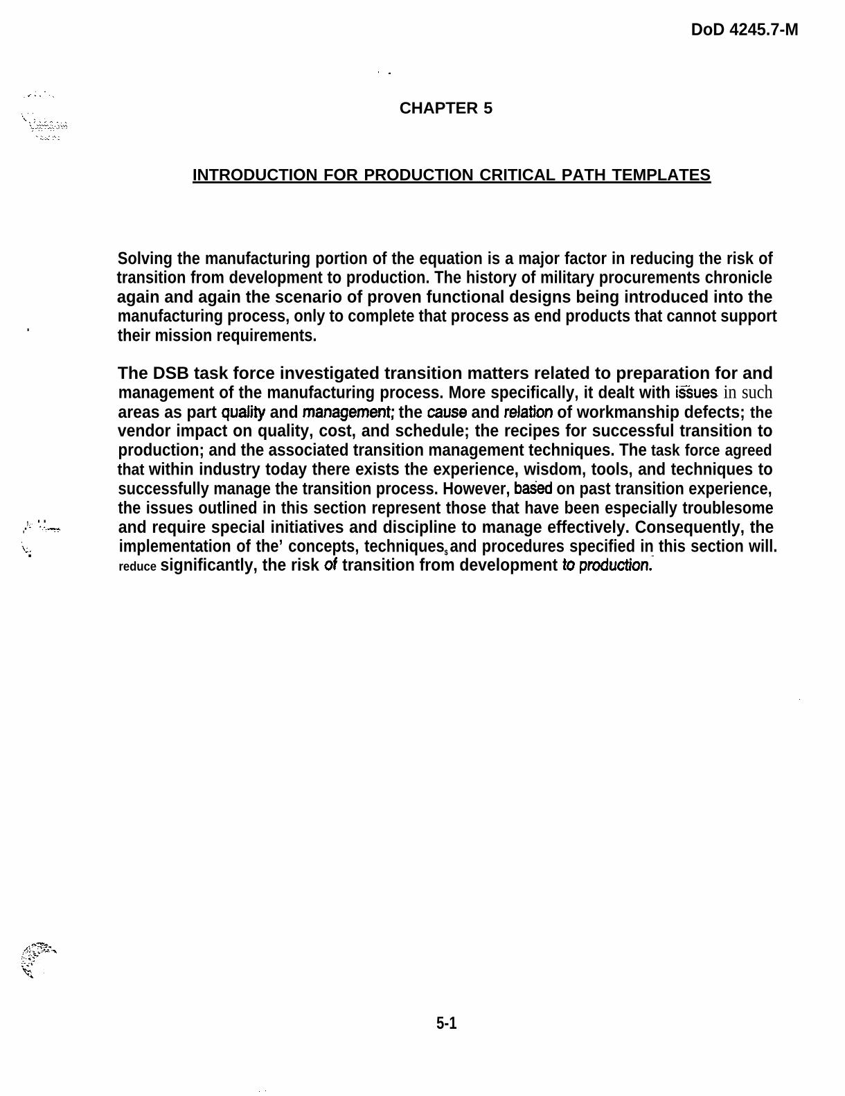
Over the years, the percentage of major weapon systems that are subcontracted hasgrown, reaching as much as 80 percent in some cases. Hence, reliance on subcontractorsand upon the skills of prime contractors to manage their subcontractors and suppliers has
increased. An informal poll of ten prime contractors averaging about ten major programseach resulted in statements that nearly half their programs were in schedule or cost troublebecause of major subcontractor problems. Clearly, the effective management ofsubcontractors needs more emphasis within industry and in the Government’smanagement of prime contractors if there is to be a smooth transition to production.
OUTLINE FOR REDUCING RISK
● Request for proposals (RFf%s) for prime contractors require responses from bidderswith equitable emphasis on subcontractor management planning versus in-housemanagement. Responses include the following:
– Prime contractor’s organization for manitging subcontractors. .
– Plans for onsite evaluation of potential subcontractors before source seiection.
– Tasks and associated payment plans to ensure that required up-front“subcontractor activities are visible.
– Plans for program reviews, vendor audits, and production readiness reviews.
● Milita~ prcqram managers and prime contractors conduct vendor conferences thataddress the following:
5-12
DOD 4245.7-M
. . . .. . . . . . . . . . .... . . . . . . . . . .. . . . . . . . ,
---
.
– Educate each subcontractor thoroughly cm the requirements in his or hercontract, as well as the key elements of the prime contract.
– Communicate to the subcontractors what is required of them.
– Provide an awareness of their role in the total weapon system acquisition.
– Allocate resources to do the job right.
– Recognize and (when appropriate) reward good performance.
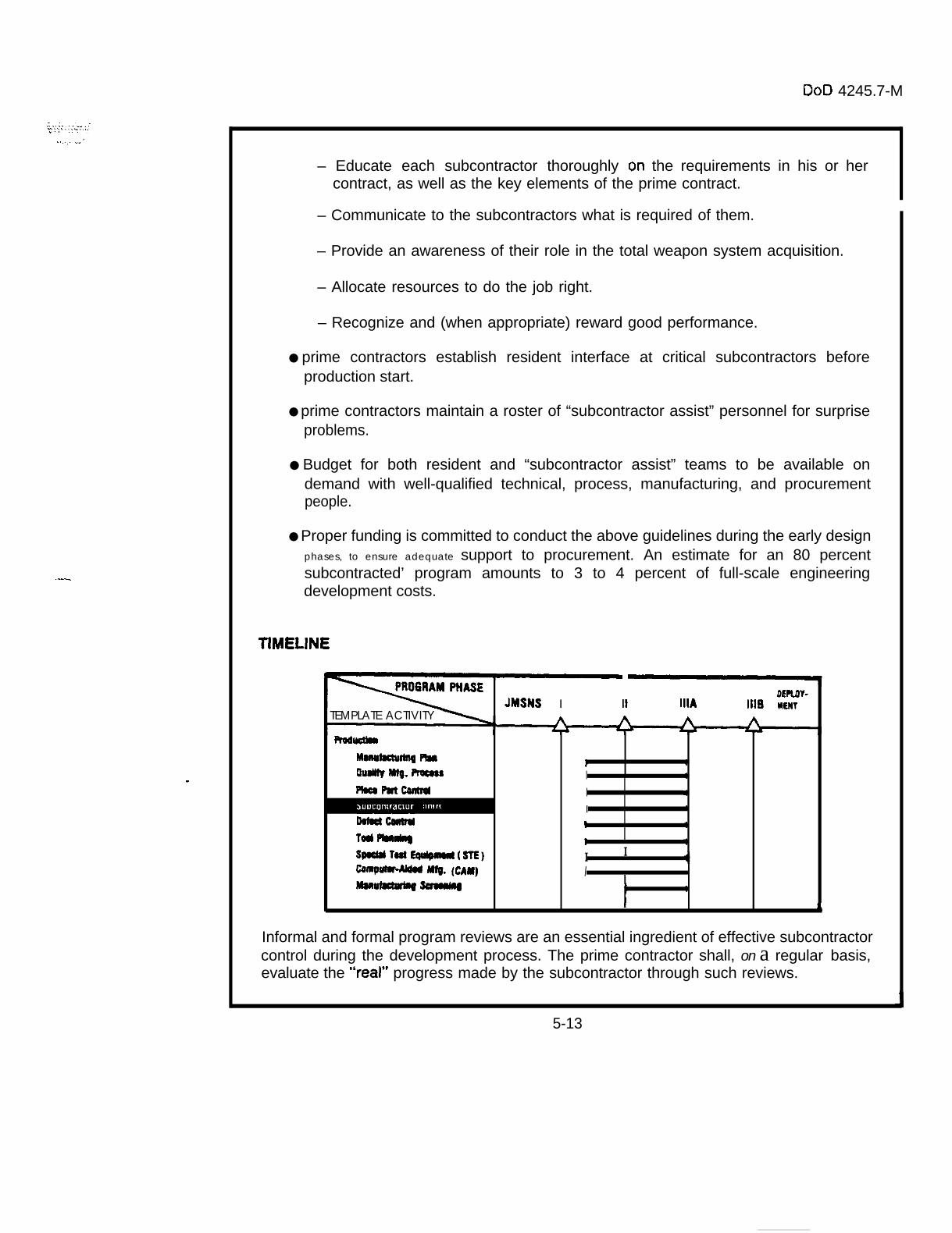
● prime contractors establish resident interface at critical subcontractors beforeproduction start.
● prime contractors maintain a roster of “subcontractor assist” personnel for surpriseproblems.
● Budget for both resident and “subcontractor assist” teams to be available ondemand with well-qualified technical, process, manufacturing, and procurementpeople.
● Proper funding is committed to conduct the above guidelines during the early designphases, to ensure adequate support to procurement. An estimate for an 80 percentsubcontracted’ program amounts to 3 to 4 percent of full-scale engineeringdevelopment costs.
TIMELINE
DEROY-JMSNS I II 111A Ills MENY
TEMPLATE ACTIVITY
RodIunmMwhdwblg ma } !aumlly M@. Roau I 1Pha PlftcoIIIYu I 1
,,D&wIL
I I I
t 1Tad ~ 1 ispoUlt TBu EQn@lmm(slE) I I
f~M w. (cm) Imwl~ ~
I1
4
Informal and formal program reviews are an essential ingredient of effective subcontractorcontrol during the development process. The prime contractor shall, on a regular basis,evaluate the “real” progress made by the subcontractor through such reviews.
5-13

DoD 4245.7-M TEMPLATEPnooucl
[I
FUNDIMGMONEYP“,S,”G
b f
&-m-@-,q-,
9ES!GN !+ 8ESIGNRWIEWS 8ELE8SE 1——I @
TEST
INTEGRATED ~ ~~j:~:~TEST SISIEM
UNI mlEST SOilWARE
Rwonr TEST
OfslwlLIMIT WE
FES1. AM,LK?C. FIELDlNO FM ,llAF, FEEOWX
I P R O D U C T I O N I I FaCilitieS I ] LocIsTIcs I I MANAGEMENT j
F❑ oofnwurm
FAC1ORV,MP#ovEMEMrs
MO nil [WI 1 vCsmn F
LOGISTICSuvwnr
*NA Yw
MBNPOWER4N0 ?fRSONNEL
SUV?QR1 AMOlFSr EO”,P14EN1
InA,M,. mlM,, ER!AL
!OUIPM %r
SPARES
~Ec H”!cAL ,.,””*LS B
WA NUFK:U RINGSrnarm
WSONNELaEO”,REMENIS
3ATBWO”(REMfN7S
T E \:SN,I CAL
a SESSH ?1
?W:19N
IT*AwrlnNPti~
1 1
AREA OF RISK
High defect rates in a manufacturing process drive up production costs because of higherrework and scrap costs. Product quality is a function of the variability of defects, that is, thehigher the number of defect types, the lower the quality and vice versa. Lack of an effectivedefect information and tracking system not only increases production costs but alsodegrades the product’s performance in the field.
OUTLINE FOR REDUCING RISK
● Types of assembly defects are identified in terms of specific data categories andpriorities for corrective action. (See figure 5-1., which applies to electronic parts.Similar figures are derived for other categories of component parts.)
I .Wm PARTS
MISwlms
[ratsslffi P*RTS
In r
PART O~CR’?AllON
~ ~-”
0W?X7 OAIA CAT’EGOMU
Figure 5-1. A$sembly Defects
. . . . . . . .. . . .. . . .. . . . . . . . . .. . . . . . ..- .. . . . . . . . ..-.- .-. .. . . .
5-14

DoD 4245.7-M
,....:. . . . . . . . . . . .-...=—> . . . . . . . . .. . . .. . . . .
●
Effectiveness of a time-phased corrective action program is tracked (see figure 5-2.)
INSPECTION
&
COMPARATORINTEGRATE COMPUTER GRAPHICS - cOLOREOCOLOR. COOEO PART BINS
CAM-AIOEO OEFECT tOENTIFtCATION0 6 BACK LIGHT PROJECTION
kCOMMON BUILO, SOLOER ANO TEST FIXTURE
LEAOFORMEll LEAOWIREOIN-LINE SEOUENCE ANO INSERTION CHECKAUTOMATIC SEOUENCE KITSCOMPUTER-AIOEO ASSEMBLYAUTOMATEO ASSEMBLY AIO
\
Figure 5-2. Corrective Action Program
Inspection and test yields and hardware throughputs are monitored continuouslywith predetermined action thresholds (see figure 5-3.)
10 UNITMOVING AVERAGE
I
I I
I
1I
o 5 10 15 20 2 s 3 0 3 5 4 0 4 5 5 0 55 50
UNITS PASSEO
figure 5-3. Performance Threshold Tracking
– Caution threshold requires engineering action:
CAUTION
ALERT
ALARM
-.. .5-15

DoD 4245.7-M,—. -. —... . . . . . . . . . . . .
:-
. s e v e n t y - t w o - h o u r m a x i m u m r e s p o n s e t i m e .
● Daily r e p o r t i n g t o p r o g r a m m a n a g e m e n t u n t i l c a u t i o n t h r e s h o l d s a r eexceeded.
– Alert threshold requires functional-level management action:
● Seventy-two-hour maximum response time.
● Daily progress reports to program management unt i l al l thresholds areexceeded.
– Alarm threshold requires full-time team action:
. Program manager constitutes team within 24 hours. .—
. Action is implemented and reported to program management within 72hours.
● Daily reports to program management until thresholds are exceeded.
● A feedback system to factoty personnel and manufacturing supewisors isestablished.
. Factory policy adequately reflects the criticality of its defect information and trackingsystem.
● Critical Rrocess yields are monitored and tracked to ensure consistency ofperfomtance (see-figure 5-4.)
0.80
5= 0.60aa&.: 0,40g ~ A
0.20
\
. . . . . . . . . . . . . . . . . . . . . . . . . . . . . . . . . . . . . . . . . . . . . . . . . . . . . . . . . . . . . . . . . . . . . . . . . . . . . . . .A.
I ‘%
!, 53 34 11 6 i 1 I o m
0. 3s O.w 0. J* O.z!l O.mt 0.0$1 0.018 0019 00s4 5.211
!
JFMAMJJ ?SQNO 1982
TOTALS
Figure 5-4. Production “Rate Test” Defects
GOAL O 20
a
TESTED
OEFECTS
mu RATE
5-16

DoD 4245.7-M
~.,.. .:.: ..
. .=.., -
TIMELINE
PROGRAM PHASE OEM4Y.JMSNS 1 II ltlA ilt6 MNT
“EMPLATE ACTIVITY
A management commitment to defect “prevention” is the prime ingredient of a sounddefect control program. A management policy on defect control is established during thedevelopment phase. This policy will require management involvement in the review ofdefect analyses and an emphasis on defect “prevention” that is flowed down to allsubcontractors.
5-17
DoD 4245.7-M TEMPLATEPRODUCT
I
1FuNOIMC
h ’MQN13m mm
t1
[
[OESIGM
[wit I I PRODUCTION
l’lli’l~)
FACILITIES LOGISTICS MAN& GEMENT
1
[ PUOFILE
OESIOM
t i
OESIGN
i
OEslGllPOucv Pmxcss Ml#lvsls
AREA OF RISK
EW1 ‘E s’ ”- 1 ~h-”d ~ ~ /rmmuc?!w7v
Cnmn
lslnoN PUN I 1 1 s 1 I
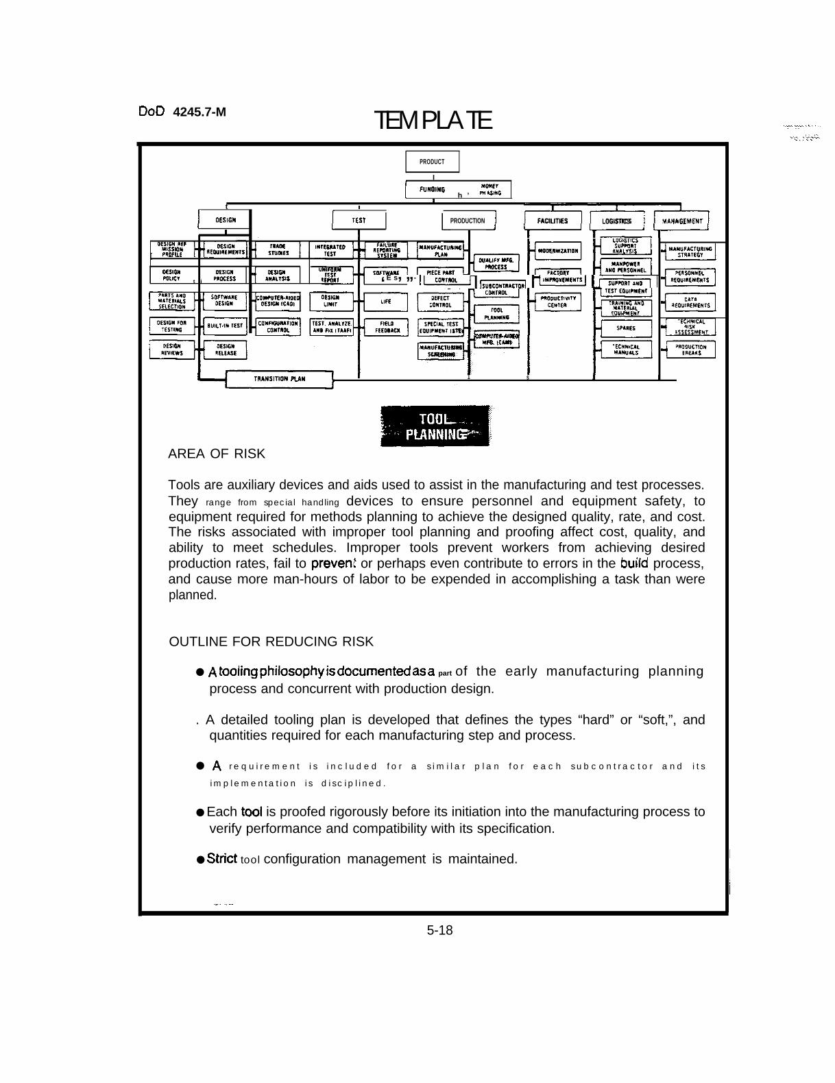
Tools are auxiliary devices and aids used to assist in the manufacturing and test processes.They range from special handling devices to ensure personnel and equipment safety, toequipment required for methods planning to achieve the designed quality, rate, and cost.The risks associated with improper tool planning and proofing affect cost, quality, andability to meet schedules. Improper tools prevent workers from achieving desiredproduction rates, fail to prevenl or perhaps even contribute to errors in the build process,and cause more man-hours of labor to be expended in accomplishing a task than wereplanned.
OUTLINE FOR REDUCING RISK
● A tooling philosophy is documerlted a.s a part of the early manufacturing planningprocess and concurrent with production design.
. A detailed tooling plan is developed that defines the types “hard” or “soft,”, andquantities required for each manufacturing step and process.
● A r e q u i r e m e n t i s i n c l u d e d f o r a s i m i l a r p l a n f o r e a c h s u b c o n t r a c t o r a n d i t s
i m p l e m e n t a t i o n i s d i s c i p l i n e d .
● Each tool is proofed rigorously before its initiation into the manufacturing process toverify performance and compatibility with its specification.
● strict tool configuration management is maintained.
.,,.. =..... . . . . . ...+ .:,...-. . . . .
I
15-18
DoD 4245.7-M. . . . . . . . . . . .~.,y..: . .+.
. . . -----
—
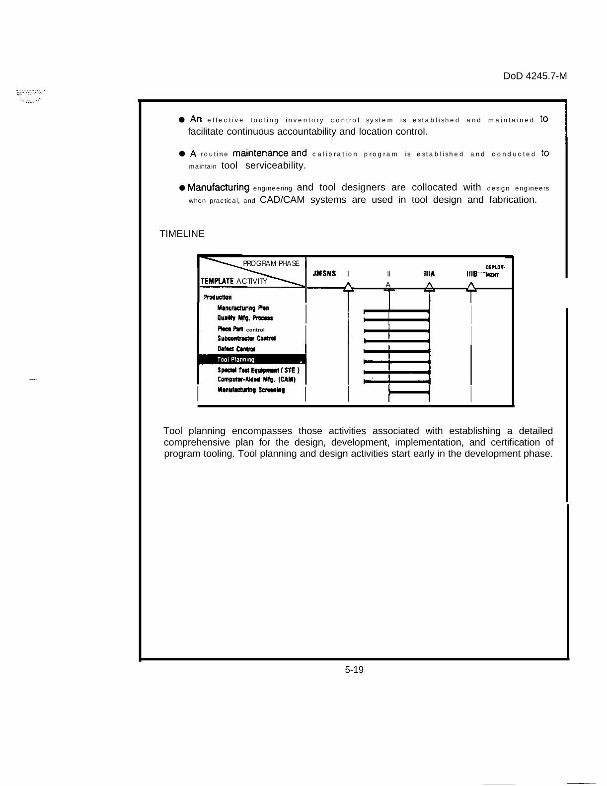
● An e f f e c t i v e t o o l i n g i n v e n t o r y c o n t r o l s y s t e m i s e s t a b l i s h e d a n d m a i n t a i n e d tO
facilitate continuous accountability and location control.
● A r o u t i n e rnaintenmce and c a l i b r a t i o n p r o g r a m i s e s t a b l i s h e d a n d c o n d u c t e d to
maintain tool serviceability.
● Manufacturing engineering and tool designers are collocated with design engineers
when practical, and CAD/CAM systems are used in tool design and fabrication.
TIMELINE
PROGRAM PHASE I OEFLLIY-JMSNS I II 111A IIIB---MENT
TEMPI.ATE ACTIVITY A AProductbn
I Mmuhcwins Rm I
auallfy ~. Romu I 1: r i II Flow Put control I
Subwntnctof cOnlrol I 1: I I IoorBd Cantrol
Spuld WI Equipnlonl ( SrE )Contpulu+kkd Mfo. {CAM) a
I MDnufuIulia~ sonbnkl~ I I } { ITool planning encompasses those activities associated with establishing a detailedcomprehensive plan for the design, development, implementation, and certification ofprogram tooling. Tool planning and design activities start early in the development phase.
5-19
—..

DoD 4245.7-M TEMPLATEr PHODUCT
1FUNOINO
AMONEYWasms J
1r
r 1 I f
DESIGN1 [
rEsrI
mooucTmr4[
F,fCIL1rtES ILocisncs MANAGEMENT
i
OcslcllUEWEW l-t! RELEBSE 1 I L ssafEumt n“ 7
F1C1ORYI WWVEWI1 S
mnoucllwlvcfN1tR
MSITl@JI MAN } —
AREA OF RISK
Special Test Equipment (STE) is a key element of the manufacturing process. It is STE thattests an article (or final product) for performance after it has completed in-process tests andinspections, final assembly, and final visual inspection. Late STE design activities and the
lack of the availability of qualified STE on the factory floor create unique technical risks.T h e s e r i s k s i n c l u d e i n c o n s i s t e n t f i n a l t e s t m e a s u r e m e n t s ( w h e n c o m p a r e d t o t e s tprocedures used during the successful development program), false alarm rates that resultin needless troubleshooting and rework of production hardware, and poor tolerancefunneling that causes either rejection of good hardware or the acceptance of hardware withinadequate performance. Program consequences in this situation are schedule delays,increased unit costs, and poor field performance of delivered hardware.
OUTLINE FOR RISK REDUCTION
● A thorough factory test plan is developed before detailed design of prime equipment.
● Adequate pflme equipment designer input and concurrence on test requirementsand test approach is required.
● Test e q u i p m e n t e n g i n e e r s a n d m a i n t a i n a b i l i t y e n g i n e e r s p a r t i c i p a t e i n p r i m e
equipment design and partitioning, test point selection, built-in test design, anddesign for test and maintenance as well as function.
● Prit?w? and sTE systems design personnel are collocated when practical.
● The test approach for completeness of test is analyzed, and a feedback loop to- correct test escapes is provided.-.
5-20
. . . . . . . .: ..:... . . . . . . . . . .-v . . . ..—
.-:...
.:

DoD 4245.7-M
.-
Test tolerance strategy is employed to catch problems at the lowest level, but doesnot cause excessive rejection of an adequate product. Tolerance incompatibility withhigher-level test is corrected.
The capabilities of the prime equipment are understood and utilized fully to achievesimplifications in STE.
Design strategies are used in test equipment that simplify tolerance changes andenable tests to be readily added and deleted. “Go/no go” tests are minimized.
Manual intervention capability is provided in automated test equipment so that theequipment can be used while final software debugging is in process (this also canaid in debugging).
Brassboard prime equipment is used, when appropriate, to begin d~bugging testequipment (this can enhance test equipment schedules).
Prime equipment design personnel are assigned’ as part of the test equipmentintegration and verification effort.
Adequate time is allotted for test equipment software debugging and compatibilityverification.
Government certification of factory test equipment is required, as well as re-certification if significant product and test equipment changes occur.
A thorough and realistic rate analysis is performed to avoid shortages of testequipment (or overbuying). Considered in this analysis are the number of expectedfailures in prime and test equipment in various phases of the program, andequipment requirements to support qualification test, TAAF, engineering problem-solving, and overhaul and repair.
Automated test techniques are used when rate requirements on the programwarrant the investment.
. .
5-21
Doo 4245.7-M
. . . .
TIMELINE
\ PROGflAM PHASE
RoduttlOaMmufutumg P18aauallry MIQ. nocna
Pkco PmtcomtfdSllbmmmcta CultrdDotut Conlrd
Tool P18MIIIM
ComWIWAldod MIIJ. fCAM)M8nufauwing Suualllg
oEmoY-JMSNS I II 111A IIIB MUIT
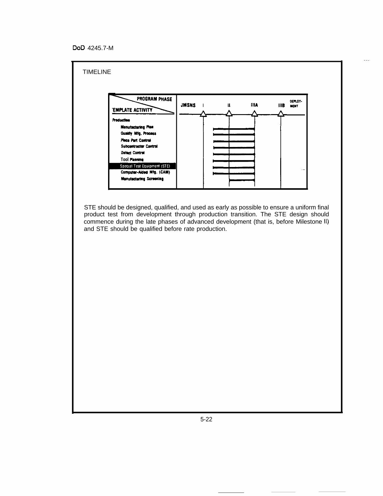
=i=lSTE should be designed, qualified, and used as early as possible to ensure a uniform finalproduct test from development through production transition. The STE design shouldcommence during the late phases of advanced development (that is, before Milestone 11)and STE should be qualified before rate production.
5-22

This Page Intentionally Left Blank
,
—.—.

DoD 4245.7-M TEMPLATE . . . . .. .--+-,..- .>::, Y*, . .
-A,, >.
P800uCT
1FUNDING lIOllEY
IP“AS,”G 1r 11 I t
DESIGN TEST1
PRODUCTION1
\ ‘ 11, :.......!,
FACILIHES 10 GIST!CS ~ ~ ~~”*~~~[fl,
1 1 i
I ,., !WOnr m “-r’s’ I ~ls”,co”r”~,a”l E
TRANSITION PUN1
1 I I I 1
AREA OF R I S K
The transition of a qualified design to the manufacturing process historically has beenaccomplished via a “drawing package, ” i n c l u d i n g n o t o n l y d r a w i n g s b u t a l s o a l a r g e
number of related documents, truly a massive amount of papenvork. Generation of thispaper lengthens the period of transition, impedes rapid and accurate communicationbetween the design and manufacturing functions during this highly volatile period, andintroduces numerous errors via the drawing package. Even some facilities that haveinvested heavily in CAD continue to transfer their designs to the factory on paper. Once thedrawing package is available, many production facilities continue to utilize outdated highrisk manual operations both to duplicate the design (“build to print”) in rate production andto manage the manufacturing process.
OUTLINE FOR REDUCING RISK
● The development of software tools for common use by industry is supported by the
D e p a r t m e n t o f D e f e n s e w i t h a p p r o p r i a t e r e s o u r c e s a n d c o o r d i n a t i o n e f f o r t s .
● A common data base between the design and manufacturing functions has inherenttechnical problems but has the highest potential payoff in product quality andproductivity.
● implementing automated manufacturing and control functions can reduce transition
t i m e b y 5 0 p e r c e n t .
● Using computers to control manufacturing operations (fabrication, assembly, test,and inspection) and to collect shop floor data can increase productivity, can reducerequired shop floor space, and can improve product quality.
5-24 .

t)otl 4245.7-fvt
. . . . .
.
●
●
●
●
●
Use of c o m p u t e r s t o c o n t r o l m a t e r i a l f l o w a n d m a i n t a i n i n v e n t o r y a n d i n - p r o c e s s
d a t a s i g n i f i c a n t l y r e d u c e s i n v e n t o r y i n v e s t m e n t s a n d s t o r a g e s p a c e .
Tooling redesign occurs when product design changes. Using CAD reduces thesedesign iterations. Therefore, using CAD for the product design and the additionaluse of CAD for tool design can reduce tooling costs by 50 percent.
Top-down strategy for implementing CAM usually increases return on investment(as opposed to replacing in-kind capability, or bottom-up).
Training and retraining plans to maintain employee morale and productivity areincluded in a company’s strategy.
See template on CAD.
TIMELINE
Fhductiorr
Mwrutacturing PlanOuallty Mfg. ProcessHam Parr $onlrtiSubcontractor ControlDafact ControlTool PtamringSpatial Test Equipmant ( STE I
Manufacturing Screening
IEPLOY.
JMSNS I 11 111A tit6 MENT IA A A
Contractors using CAM integrated with CAD are experiencing improved productivity. Withmanufacturing personnel involved in the design process, a common CAD/CAM data basecan be established resulting in reduced risk in the transition from development toproduction.
I
I
5-25
.—

DOD 4245.7-M TEMPLATE
e.lNTCIIMTEO MLLMF
TEST R:JO:;*M
u RITEST Sommnf
Rf PORT TES1
OESIGMu ml LIFE
TEST MIAL”2E. F,ELOAN* FM ,llAF, FFEDMCK
1 I
[PnOnucl IiFUNOIN6 MONEY
m bsulc
i,
1 1 1 1 (D&ml/ I I rfsl
/ [PRowSrm#
/ [FAC)LIWS LOGIS1lCS
HM4N.WEMEN1
-1
LOGIS1lCSSuf?onr
MooEnnlrAr,on ,“81?s,s
MAllmn
F8cTaRv AND FtnSOtIHfL
+
‘ ~“’” 1=
PtRSOMMELlWn0vcMEH7s
SU?RU1 DlloRfOUIRf HEMIS
rcs r EouuwfnrPRooucnvllr
rnm”t”a A*3A1A
CENTER ,~fll,;Jl#NLr 8EOU,WMfN11
1 E ,p::cusP#n4s
A SES5MENT
I:~:[SL PnoJIJJoll
m
TRAMStTIOM PLANt
1 1 J 1 J
AREA OF RISK
Environmental stress screening (ESS) is a manufacturing process for stimulating parts andworkmanship defects in electronic assemblies and units. Although ESS has been proven toreduce field failure rates by 20 to 90 percent (reducing life cycle costs) and to reduce in-plant failure rates by as much as 75 percent (reducing production costs), its use is still notaccepted universally by many contractors as a standard part of their manufacturingprocess. When ESS also is performed during development, it helps to ensure that theelectronics hardware performs on demand, that the most effective screening levels aredetermined before high rate production, and that possible part type and vendor problemsare discovered early. Analysis of failures experienced on unscreened developmentalsystems has indicated that 60 percent are due to workmanship, 30 percent are due to badparts, and only 10 percent are design problems. ESS should not be confused withenvironmental qualification testing (which is designed to demonstrate design maturity).
OUTLINE FOR REDUCING RISK
● ESS procedures are established during development.
● Temperature cycling and random vibration are effective” environmental stressscreens and are performed on 100 percent of electronic products (it is not done on asampling basis).
5-26

DoD 4245.7-M
~ +..:.> ... . . . . .$>~$’+;+,, . . . .. by..:.:..
:-
. The predominant factors in temperature cycling are:
– Rate of change of temperature.– Minimum and maximum range of temperature.– Number of cycles.– Level of assembly on which performed.
● The predominant factors in random vibration are:
—Spectral density.— L o w e r a n d u p p e r f r e q u e n c y l i m i t s .
— A x i s o f s t i m u l a t i o n .
— L e v e l o f a s s e m b l y .
— D u r a t i o n o f s c r e e n .
● Random v i b r a t i o n s t i m u l a t e s m o r e d e f e c t s t h a n f i x e d o r s w e p t ~fie v i b r a t i o n o f
s i m i l a r l e v e l s o f e x c i t a t i o n .
● There are many technical and cost benef i t t radeof f s to be made in des ign ing an ESS
program. A part icularly useful document in making tradeoff decisions is theEnvironmental Stress Screening Guidelines for Assemblies.l A screening guidelinesdocument for parts will be published by the IES in late 1985.
● Recommended starting conditions are:
—Random Vibration:
● Spectrai density: 6g rms. Frequency limits: 100-1000Hz● Axis: 3● Duration: 10 min.
—Temperature Cycling:
● Rate: 10“C/minute● Range: – 40”C to 60*C● Number of cycles: 15 (last must be failure free)● Powen On (except cool down)
● For greatest return on investment, vigorous correcWe actions are made to’ adjustmanufacturing process to minimize recurrence of defects.
● The ESS program is a dynamic one. Procedures are adjusted, as indicated byscreening results, to maximize finding defects efficiently.
‘Sponsored by the Institute of Environmental Sciences (lES), September 19S4.
-. .5-27
-.

DoD 4245.7-M . . . . . . . . ::..— ..._.”
. . . . . . .
●
●
Objective of ESS is not to find design defects, although such may be a by-product.
Appropriate screening for manufacturing defects, as an acceptance test, isdeveloped for other than electrical and electronic products.
TIMELINE
DEPLOY-
EMIIATE ACTIVITY
WmnOnMMurKWllll~ ml I 1Illmsty mfg. Ffowss L Iflu, WI control ISubwnimIW ControlOorul controlTool R8anlnQSPUIU lost &@pllWlll ( STE )C@mputw-AM@ Mfg. (CAM) I
ESS techniques precipitate assembly and workmanship defects, such as poor soldering or
weak wire bonds during the assembly process.
-.
5-28