Embed Size (px)
Citation preview
ED 246 302
AUTHORTITLEINSTITUTION
REPORT NOPUB DATENOTEAVAILABLE FROM
PUB TYPE
DOCUMENT RESUME
CE 039 365
Lengert, GerryDrywall Finishing Manual.British Columbia Dept. of Education, Victoria.Curriculum Development Branch.ISBN-0-7718-8362-583265p.; Publishing financed by Ministry of Labour.Publication Services Branch, Ministry of Education,878 Viewfield Road, Victoria, BC V9A 4V1 ($10.00).Guides Classroom Use Materials (For Learner)(051)
EDRS PRICE MF01 Plus Postage. PC Not Available from EDRS.DESCRIPTORS *Apprenticeships; Behavioral Objectives; Buildings;
*Building Trades; Carpentry; Ceilings; Competence;Competency Based Education; *Construction (Process);Construction Costs; Construction Industry;*Construction Materials; Construction Programs;Equipment; Foreign Countries; Hand Tools; *JobSkills; Learning Modules; Lesson Plans; MachineTools; Postsecondary Education; Safety; StateCurriculum Guides; *Structural Elements(Construction); Task Analysis; Trade and IndustrialEducation; Units of Study; Vocational Education
IDENTIFIERS British Columbia; *Drywall Construction
ABSTRACTThis manual, a self-study guide for apprentices in
the drywall finishing trade in British Columbia, attempts toestablish standards for the trade. It tells how to produce a properlytaped and filled drywall surface and describes what that surfaceshould look like. The standards emphasize quality work that can berealistically achieved on the job. Wherever possible the manualdivides aspects of drywall finishing into step-by-step procedures.Safe, efficient use of the body in performing finishing tasks isstressed in the procedures. Besides procedures, the manual also dealswith knowledge related to drywall finishing. The manual consists of11 modules covering the following topics: filling compounds, safety,applying bead, taping and wiping tapes, filling, texturing, repairsand corrections, factors affecting drywall finishing, workingefficiently, maintenance of tools and machines, and estimating. Eachmodule contains an introduction that describes the contents of themodule; an information section illustrated with tables, linedrawings, and photographs; a summary; and exercises. An answer keycompletes the manual. (KC)
******************************k****************************************
Reproductions supplied by EDRS are the best that can be madefrom the original document.
***********************************************************************
wall Finishinganuai NATIONAL INSTITUTE OF EDUCATION
OA DEPARTMENT 0I- EDUCATION
E oCATIONAL RESOURCES INFORMATIONCENTER IERICI
ins dowment has Leen reproduced aSreco0ed troM the person or *mandato:0nOngmalev AKos changes have been made to mbrOverephoduchOn quahly
Pants of s.QW or oomions strtod .0 rfus d4Cu
r-nt 00 not netessanhe woresent othcla. Alk6,0$4.00 oi pOla v
BC'PERMISSION TO REPRODUCE THISMATERIAL IN MICROFICHE ONLY!AS SEEN GRANTED BY
(TO THE EDUCATIONAL FtrOURCESINFORMATION CENTER (I:gIC)"
to
w
Drywall FinishingManual
Developed byResearch and Curriculum Development BranchMinistry of EducationPublishing financed byApprenticeship and Employment Training DivisionMinistry of Labour
0BC1983
3
Canadian Cataloguing in Publication DataLengert, Gerry
Drywall finishing manual
Written by Gerry Lengert. Cf. Acknowledgements."Publishing financed by Apprenticeship and Em-
ployment Training Division, Ministry of Labour."ISBN 0-7718.8362-5
1. Wall board - Handbooks, manuals, etc. 2.Plastering - Handbooks. manuals, etc. I. BritishColumbia. Research and Curriculum DevelopmentBranch. II. British Columbia. Apprenticeship and Em-ployment Training Division. III. Title.
TH8131.146 693'4'028 C83-092148-6
For further information contact:Coordinator, Construction and Eectrical ProgramsPost-Secondary DepartmentMinistry of Education7451 Elmbridge WayRichmond, B.C. V6X 1B8Telephone: (604) 278-3433
Copies of this publication ran be ordered from:Publication Services BranchSchools DepartmentMinistry 0: Education878 Viewfield FoadVictoria, B.C. V9A 4V1Telephone: (604) 387-5331
Ministry of Education, Province of British Columbia, CanadaNo part of this publication may be reproduced in any for i without permission inwriting from the publisher.
Acknowledgements
The Ministry of Education would like to acknowledge Gerry Lengert of PacificVocational Institute for writing the Drywall Fnutheng Manual.
The Ministry also wishes to acknowledge contributions to the manual from:
Ames taping tool systems co.Columbia Taping Tools CanadaThe Drywall Finishing Trade Advisory CommitteeDan GaymanGene LengertWalter PidgeonAI Vince
5
Introduction
This manual attempts to establish standards for the drywall finishing trade. It tells howto produce a properly taped and filled drywall surface and describes what that surfaceshould look like. The standards emphasize good quality work that can be realisticallyachieved on the job.
Wherever possible the manual divides aspects of drywall finishing into step by stepprocedures. For example, four procedures are gi..en for applying the first filling coat toa butt joint. These procedures provide the basis for a finisher to master and build uponto become a competent tradesman. Safe, efficient use of the body in performingfinishing tasks is always a concern in the procedures.
Besides procedures, the manual also deals with knowledge related to drywall finishingFilling compounds and beads are discussed, as are the use and maintenance of toolsand the effects that temperature, humidity, and ventilation have on drying fillers. Theknowledge is not an extra or a frill; it has practical applications to the day to day workdone by finishers.
After studying a module, you should do the exercise located at the end of each moduleto see what you have learned. Answers to the exercises are provided at the end of themanual. "Sleuth Sheets" are given in the taping and the filling modules to help yousolve problems in your finishing work.
iii
Module 1: Filling CompoundsIntroduction. 1General Characteristics of Filling Compounds. 1Filler Formulations. 2Fillers in Filling Compounds, 3Casein Slow-set Filler. 5Vinyl Slow-set Filler. 5Pre-mix Fillers. 6Fast-set Filler. 7Water Absorption and Drying. 8Filler Problems Related to Moisture and Drying. 9Mixing Fillers. 10Definitions Related to Filling Compounds. 11Summary. 11Exercise. 12
Module 2: SafetyIntroduction. 13Injuries Common to Drywall Finishers. 13Minimum Stress Trowelling Techniques. 15Minimum Stress Techniques with Taping Machines. 16Safe Practice with Stilts and Scaffolds. 17Constructing Safety Railings. 18Working with Ladders. 18Safety Precautions with Floors. 19Electrical Equipment Precautions. 19Pressurized Equipment Precautions. 20Dust Protection. 20Eye Protection. 21Noxious Fume Protection. 21Hearing Protection. 22Head Protection. 22Summary. 22Exercise. 22
.. 7
Contents
V
Contents
Module 3: Applying BeadLitroduction. 23Beads. 23Edge Trims. 26Other Beads and Trims. 30Measuring and Cutting Beads and Trims. 30Plumb, Level and Straight. 35Attaching Metal Corner Bead. 36Attaching Glueon Beads. 39Summary. 42Exercise. 43
Module 4: Taping and Wiping TapesIntroduction. 45
Hand Taping. 47Tape. 47PreFilling. 47Dry Method Hand Taping. 47Dry Taping Butt Joints. 49Dry Taping Flats. 50Applying Short Tapes. 51Dry Taping Angles. 52Cleanup Procedures. 53Hopper Method Hand Taping. 54Hopper Taping Walls. 56Hopper Taping Ceilings. 57Hopper Taping Sleuth Sheet. 59Banjo Method Hand Taping. 59Exercise. 60
Machine Taping. 63Tools. 64Loading Rolls of Tape. 64Filling a Taping Machine. 66Rinsing the Machine Head. 68Taping Sequence for Machines. 68Procedures with a Newly Filled Bazooka. 69Basic Procedures for Machine Taping Joints. 69Jammed Blades. 72Short Tapes with Machines. 73Taping Machine Holding Positions. 73Keypoints with Taping Machines. 75Machine Taping Closets. 75Machine Taping Valances. 76Cleaning a Taping Machine. 76
vi 8
Bazooka Courtesies. 77Machine Taping Sleuth Sheet. 78Exercise. 81
Wiping Tapes. 83Hand Wiping Tools. 83General Points on Wiping. 84Wiping Sequence. 86Wiping Butt Joints. 87Eliminating Wrinkles. 88Wiping Flats. 89Wiping Short Tapes. 89Wi ing Angles by Hand. 90Rolling Angles. 92Flushing Angles. 93Wiping Angle Bottoms. 94Wiping Threeways. 94Wiping Non 90° Angles. 96Cleanup after Wiping. 98Wiping Butts and Flats Sleuth Sheet. 99Wiping Angles Sleuth Sheet. 101Exercise. 104
Contents
Module 5: FillingIntroduction. 105The Right Filler for the Job. 105Pre-filling. 106Telling if Filler is Dry. 107Types of Filler Coats. 108Holding a Knife for Filling. 111Holding a Trowel for Filling. 111Basic Filling Passes (or Strokes). 112Joining Wet Filler. 114Rough Sanding. 114Filling Vertical Bead. 115Filling Horizontal Bead. 118Filling Narrow, Parallel Beads. 118Filling Intersecting Beads. 119Filling Butt Joints. 122Filling Butt Joints on Curved Surfaces. 123Filling Flats on Curved Surfaces. 125Filling Uneven Butt Joints. 125Filling Flats. 126Filling Butts and Flats with Machines. 127Filling Machines (Boxes). 127Loading Filling Boxes. 129
vii
9
Contents
Filling Box Combinations. 130Filling Flats with Boxes. 130Filling Butts with Boxes. 131Filling Ceilings with Boxes. 1.'2Filling Fasteners by Hand. 133Filling Nails Singly. 135Filling Fasteners by Row. 135Filling Machines for Fasteners. 136Filling Fasteners with a Box. 137Filling Angles. 138Filling Angles by Hand. 138Filling Angles with Machines. 140Filling Bottoms and Threeways. 142Filling Non 900 Angles. 142Filling Rounded Angles. 143Tool Cleanup. 145Finish Sanding. 145Final Inspection. 146Summary. 147Filling Sleuth Sheet. 151Exercise. 153
Module 6: TexturingIntroduction. 157Types of Wallboard Texture. 157Acoustic Texture. 158Glitter. 158Surface Preparation. 158Design Layouts. 159Using Color. 162Masking. 164Undercoating. 165Airless Paint Machines. 167Texture Machines. 169Factors Affecting Texture Appearance. 170Regulating Texture Appearance. 171Texture Spraying Techniques. 172Finishing off Ceilings after Texturing. 174Hand Texturing. 175Summary. 177Exercise. 178
Module 7: Repairs and CorrectionsIntroduction. 179Repairing Gouges, Ridges and Other Defects as You Go. 179Patching Holes. 182
viii
10
Contents
Keying Painted Surfaces. 186Repairing Previously Finished Wallboard. 186Repairing Damaged Plaster. 188Repairing Damaged Textures. 189Summary. 190Exercise. 191
Module 8: Factors Affecting Drywall FinishingIntroduction. 193Finish Schedules. 193Examples of Finishing Schedules. 196Blueprint Written Specifications. 197Moisture Content in Wood Framing and Wallboard. 199Proper Drying Conditions for Filler. 200Checking for Inspection SlipUps. 202Method of Taping and Filling. 207Handling and Storage of Materials. 208Protecting Nearby Surfaces. 209Summary. 210Drying Chart for Joint Filler. 213Room Finish Schedule Example 1. 214Room Finish Schedule Example 2. 215Room Finish Schedule Example 3. 216Interior Finish Schedule Example 4. 217Exercise. 218
Module 9: Working EfficientlyIntroduction. 219Organizing Tools and Equipment. 219Identifying CostEfficient Use of Materials. 220Checking Work. 220The Individual Versus the Team Approach. 220Mirk Systems. 221Summary. 221Exercise. 222
Module 10: Maintenance of Tools and MachinesIntroduction. 223Maintaining Hand Tools. 223Maintaining Machines. 225Repairing Machines. 226Repairing Hoppers and Banjos. 227Repairing Taping Machines. 227Repairing Angle Rollers and Flushers. 232Repairing Filling Boxes. 232Repairing Hand and. Pole Sanders. 232
ix
11
Contents
Repairing Airless Paint Sprayers and Texture Machines. 233Summary. 233Exercise. 234
Module 11: EstimatingIntroduction. 236Blueprints. 236Calculating Areas from Blueprints. 237Estimating from the Job Site. 239Other Factors when Costing a Job. 241Summary. 242Exercise. 243
Answer KeyModule 1. 245Module 2. 240Module 3. 246Module 4:
Hand Taping 247Machine Taping. 248Wiping Tapes. 249
Module 5. 250Module 6. 253Module 7. 254Module 8. 254Module 9. 255Module 10. 256Module 11. 256
x
12
Filling CompoundsMODULE I
INTRODUCTION
Although lrywall finisting is a relatively new trade in the construction industry, fillersare not new compounds. In fact, some filler-like substances are not man-made. Aquaticanimals have known the secret of fillers for millions of years; clams, mussels, oysters,crabs, and other shellfish produce compounds for their shells that are similar todrywall fillers.
Both drywall filers and sea shells are basically limestone and glue. Glues such aspolyvinyl acetate, polyvinyl alcohol, and casein are used in drywall fillers in com-bination with limestone, dolomite, and gypsum. In the oceans these minerals floatfreely, allowing the shellfish to "mine" them with very little effort. Shellfish secreteglues which mix with the limestone and harden to become their homes. Millions ofdollars have been spent to find a binder as suitable for our purposes as the naturalbinders are for the shellfish. Unfortunately the mollusc hasn't been of much help hereas it has clammed up about its formula.This module di cusses basic formulas for drywall fillers, and also discusses what af-fects the ingrec ants in fillers have on the work of the drywall finisher. Knowing moreabout filler, about how it works and what it can and can't do, will help finishers tobetter use the material and avoid problems with it.
Note that as the demands of the industry change, so do filler formulas. Thus the in-formation here is general and may not always apply to a specific brand.
General Characteristics of Filling CompoundsDrywall filling compounds are more closely related to latex paints than to plaster. Latexpaint and drywall filler have the same basic formula and some of the same ingredients.Both latex paints and drywall filling compounds are adhesives in that they rely on a bin-der or glue to internally bond their ingredients and also to externally bond the materialto a surface. When dry, filling compounds exhibit the same characteristics as latexsealers.
Filler is an emulsion; it can be compared to mayonnaise, an emulsion of oil, water,eggs, and vinegar. Oil and water do not mix, but when the other ingredients of mayon-naise are mixed with the oil and water separation does not occur. The same thing happens with filler the particles are suspended in the water and do not float or settle.This thick emulsion has the property of changing from a semi-solid to a liquid at thepoint of being sheared or cut with a blade, then returning to a semi-solid immediatelyafter the blade ha.> passed through. This property, called thixotropism, is necessary toproduce a smooth surface on a filler with a trowel.
13
1
Module 1
Since filler is cut when worked by a blade, the edges of erywall trowels and knives mustbe filed to a sharp square so that they can easily cut thraugh the filling compound andnot float over it. Note that the opposite is true with plaster. Flastering tools must floatover the plaster to make it smooth. If cut, the coarse aggregate in the plaster will causetears or pulls in the surface.
Filler FormulationsNot many drywall finishers realize what goes into filler, and how accurately theingredients must be balanced to attain the critical blend of properties necessary tomake the filler work properly both during application and after it has dried. Filler is acarefully formulated material. Few other products that cost so little have so much ex-pected of them.
Filling compounds consist of a binder and functional fillers, and are compoundedeither as a powder, which is mixed with water to the proper consistency before ap-plication, or as a pre-mixed paste. Powdered fillers are being phased out by the moreconvenient pre-mixes.
Important qualities in filling compounds are: minimum slacking-off (thinning) after ad-ding water to powdered filler and letting it stand; minimum slump; easy trowelling,smoothing, and sanding; good tape adhesion; good flexibility; minimum shrinkage; andresistance to edge-cracking. These properties are determined by the type and propor-tions of binders and fillers and the amount of water added.
It is important to note that manufacturers cannot formulate a filling compound thatwill match every job condition, nor can they produce a filler that will salsify everyfinisher's desires. What they can do is formulate for a certain area, climatic condition,or for general expectations of localized finishers. For example, filler applicators in Ed-monton prefer a hard surface on their finished product. In Vancouver, finishers preisr asofter, easier-to-sand material. Fillers formulated for the humid conditions in Vai.-couver will not react the same in the drier conditions in Edmonton and vice versa. Thisperhaps is why small, local companies specializing in filler often are more successfulin meeting the local needs than national companies.
Because of the complexities in formulating filler, it is absurd for a drywall finisher withno training in chemistry and no knowledge of manufacturers' formulations to attemptto mix different fillers to produce a better batch. In fact, the attempt to do so couldresult in damage claims against the finisher or the employer, and they couid not fallback on the manufacturer of the fillers because manufacturers' warranties are can-celled if different fillers are mixed together.When discussing fillers there are several trade terms that recur:1. "Water demand" refers to the amount of water a filler requires to make the
product workable. Generally, a high water demand is undesirable as it increasesshrinkage and the risk of edge-cracking.
2. "Workability" refers to how easily a material smooths out or how much pressuremust be put on the blade to cut the filler. Some fillers allow the blade to easilyslide over the surface and leave it smooth. Other fillers will stick to the blade,leaving elongated holes called "fish eyes" or a rough surface. The better theworkability, the easier the job of the finisher and the faster the work progresses.Poor feathering or thick edges is another indicator of poor workability.
2
14
a
Filling Compounds
3. "Flexibility" is important in resisting cracking caused by movement of the surfacethat the filler is applied to.
4. "Slump' refers to how the filler reacts when absorbing water. Vinyl filler generallythins out as it absorbs water.
5. "Open time" is the time that c filler can be worked before it will pull or tear. Opentime is the time between the application of the filler on the wall and the formationof a film on the surface of the filler. Once this film is formed, any disturbing of Itwill cause a tearing of the surface of the filler. The formation of the film is depen-dent upon the rate of water loss. Therefore, the longer the water is retained thelonger the open time of the filler. Loss of water can be retarded by adding fibrousmaterial to the filling compound.
There are four parts found in all unmixed filling compounds: filler, binder, bindermodifiers, and additives (Table 1-1). Filler is the bulk of the compound. It is the visiblepart of the compound after water has been added. Binder holds the filler together andadheres it to the wall. Without a binder the filler would powder and not stick to thewall. Binder modifiers allow the binder to flow among the particles of the filler, congealthe emulsion, and prevent the filler from rotting. Additives give the filling compounddesired performance characteristics (Table 1-2). Most additives are trace elements inthe formula; there can be as many as 20 of them in a filler.
Table 1.1Parts of a Filling Compound
Fillers Binders Bin derModifiers
Additives
Calcium carbonate Casein Dispersants: See Table 1.1(limestone) (powder) borax, glycol
alcohol, soap
Magnesit' carbonate Soya protein Plasticizers:(dolom..4 (powder) carboxy Methyl
cellulose, Mica
Calcium sulphate Polyvinyl acetate Preservatives:(gypsum) (powder or emulsion) Mercury
compoundsStyrene-butadiene
(emulsion)Polyvinyl alcohol
(powder or solution)
Fillers in Filling CompoundsThe principle ingredient of filling compounds is filler which can be calcium carbonate(limestone), Magnesium carbonate (dolomite), or calcium sulphate (gypsum). Filler sup-plies the bulk of a filling compound (from 50 to 70 per cent) and keeps down the costof the compound. Calcium carbonate is the preferred filler because of its low cost, low
1153
,
Module 1
water demand, good workability and desirable color. It has a resistance to shrinkageand edge-cracking and is easily smoothed 2nd sanded. Dolomite has the disadvantageof being a dark color, and calcium sulphate is more expensive than the other fillers andhas a higher water demand.
The finer grades of calcium carbonate re ;wire higher proportions of water and binder,and are slightly more difficult to work. On the other hand, if the grade is too coarse, thesurface finish is not smooth and undesirable grit will be present.
Table t-2Filler Additives
Ingredient Effect
Ammonia Solvent used co soften casein and enable it to mixwith water.
Asbestos A fibrous talc that provides open time, internalbonding, water retention. Prevents edge-cracking,provides stable viscosity and slickness, andimproves sanding. No longer used in filler.
Attapulgite Clay A fibrous material used as a replacement forasbestos, but does not react chemically the sameas asbestos in filler. Has the same morphogenicproperties.
Seas Solvent used to soften casein and enable it to mixwith water, but will react with vinyl binders anddestroy them. Used in the core of gypsumwallboard to provide air bubbles to lighten sheets.
Carboxy Methyl Cellulose Promotes workability; wood fibre.
Clay, Talc Improves sanding but increases water demand andmakes material difficult to smooth out.
Glycol Alcohol Gives open time and smoothness. Also a dispersantwhen mixing pre-mix fillers.
Mica Improves workability, flexibility and crackresistance.
Potassium Tril olyPhosphate
Dispersant. Permits water to mix readily with drypowders.
Silica Used as a replacement for asbestos; foundnaturally with calcium carbonate.
Soap Increases workability, but creates air bubbles whenused with attapulgite clay.
Starch Used to make filler hard, and as a bonding agent.
4
16
Filling Compounds
Calcium carbonate is a mineral and will not decompose when exposed to air. However,if a room is not ventilated properly and if it is heated with propane heaters, a build-upof sulphur dioxide and moisture will create an acidic mixture that will react with thelimestone and cause it to discolor.
Casein Slow-Set FillerAlthough casein filler is not used much anymore, it is important to understand how itdiffers fiom the more common vinyl filler. There are those in the industry who don'trealize the two types of fillers are different and expect vinyl filler to perform in thesame way as did the casein. This misconception has caused quality problems.
The milk by-product, casein, is a binding agent. Casein, or blends of casein and soyaproteins, were used at approximately 5 to 14 per cent by weight of total formulation.Because casein filler putrified, it was normally compounded only in dry mixes.
Casein filler produced perhaps the most positive form of bonding of all the fillers, butit had a major drawback. The mixed life of the filler was short. If casein filler wasmixed and left in the pail for more than 24 hours, it rotted causing a horrible smell. Asthe casein decomposed, the filler lost its bonding properties and the effects showed upas cracking or peeling of the filler after it was dry. The mixed life of the Viler waslengthened to some extent by the addition of mercury.
Casein filler was a good filler to use in humid situations. It would stay on the wall for along time without drying, and as long as the temperature was gradually increased thecasein filler would still bond.
Casein filler not only was more tolerant of moisture than vinyl fillers while drying, butalso was less susceptible to the effects of moisture after it dried. In cases where theceiling had been sprayed and the overspray scraped off the top angle, the angles filledwith a casein topping filler were not likely to have the filler scraped off. Once drycasein filler would riot soften in water very easily.
Vinyl Slow-Set FillerThe main part of slowset vinyl filler is limestone or dolomite, the same basicingredients of casein filler. The difference between the two is their bonding agents.Vinyl filler uses a vinyl compound (polyvinyl acetate) as a bonding agent. In much thesame way that rubber glue forms a film at the surface when exposed to air, vinyl fillerforms a film that extends throughout the drying filler crating physical bonds that givethe filler internal strength. Powdered keetones and alcohols are added to vinyl fillerand readily accept water. Thus vinyl filler mixes faster and smoother than casein fine!The adhesion of vinyl compound, while not as good as casein, is still more thanadequate to produce quality work. As the filler dries, moisture is retained in thechemical compounds, but short fibres may be added to lengthen the drying time.
Vinyl filler dries best at the upper end of the temperature-humidity scale. Generallyspeaking the higher the temperature the better the drying process. The opposite wastrue for the casein fillers; they dried best at the lower end of the temperature-humidityscale. It is on this point where the difference between the two fillers has causedproblems. Some finishers mistakenly think that vinyl filler has the same drying charac-teristics as the old casein filler.
17
5
Module 1
There should be no cracking problems with vinyl filler unless there is an extremelyheavy fill. Vinyl filler can be mixed with water of any temperature and a smoothmaterial will result. Mixed vinyl filler will last longer than casein fillers but should bediscarded after 48 hours because it may not adhere properly. Vinyl filler must drywithin 72 hours of application, since the binder gradually decomposes and loses itsbonding power when kept wet.
Jihyl filler comes in powder form in bags and also in a pre-mixed form.
Taping, Topping, and All-Purpose FillersThree types of vinyl filler are made in both powdered and pre-mix form: taping, topping,and all-purpose. They are produced from basically the same materials but by jugglingthe formula they exhibit different properties.
Taping filler should be hard and have good external and internal bonding. Smoothnessis not of concern ecause the filler is not used as a finish coat. Taping filler is made bymodifying the basic formula in one of two ways. The first one is to decrease the propor-tion of limestone therefore increasing the proportion of binder; the second is to leavethe limestone the same but increase the amount of binder. In either case the proportionof limestone is decreased and therefore there is less demand on the binder to hold thematerial together. This makes a harder material owing to the greater amount of freebinder for external bonding. Besides being harder than the basic formula, taping filleralso shrinks more.
Topping filler must be soft, have little shrinkage, and produce a smooth, polished sur-face. A strong bond is not desiratle because the topping filler is applied as a skim coatfor finishing. To make a topping filler, the proportions of limestone and binder (to alesser degree) are increased. The increased proportion of limestone makes the fillersofter owing to the greater demand on the binder. Note that topping filler should not beused for taping because there is not enough free binder to give a good external bond.
All-purpose filler should be all the things that taping and topping filler are, but usuallyfalls somewhere between the two. It does not have the same adhesive ri: opoerties astaping filler, nor the smooth, polished surface of topping filler. The main advantage ofall-purpose filler is that one type of filler can be used throughout the job. A disad-vantage is that all-purpose filler is more susceptible to failures caused by job con-ditions than are the specialized fillers.
Pre-mix FillersPre -mil vinyl filler has essentially the same composition as powdered filler. It is com-bined with water at the factory in a large mixer that produces a more uniform mix thancan be made on the job.
Pre-mix filler is a relatively new product and as such has new problems. Powdered fillercan be mixed, bagged, and sent from the factory to the job site with reasonable con-fidence that it will not change. Pre-mix filler is shipped as an emulsion and can un-dergo many changes between the factory and the job. Blocking (the solidifying or stif-fening of the filler) occurs when the heavier materials settle to the bottom while thebinder and other liquids float to the top. Sometimes the filler will lose its consistencyand become as thin as water. Sometimes the color of the filler will change. Unless youundet.tand the chemical composition of the filler, it is almost impossible to determine
6
18
Filling Compounds
why these things happen. Usually the problem can be traced to a minute chew: in thesupplier's formula. The change may constitute only .01 per cent of the total formula butt can do all sorts of strange things. In most instances the filler can be re-mixed on the
job and used, but at is best to contact the manufacturer's representative to determinewhat happened.
Pre-mix filler should never be made thicker by the addition of a powdered filler. Thechemical reaction caused by mixing the two different fillers could produce a defectivefiller. Instead, use only premix filler of the same type and manufacturer to thicken apre-mix.
A primary complaint about pre-mix filler is that there is a lot of water in the box andthis makes i° too expensive. Actually, there is no more water than the amount needed tomix a powdered filler. The water must be paid for whether it is pre-mixed into the filleror someone's wages are paid to fetch it.
Another complaint is that pre-mix filler must be re-mixed before being .used. This istrue, but powdered filler must be re-mixed two and sometimes three times before a pailof it can be used. Once pre-mix is re-mixed it maintains its viscosity while powdersgenerally do not.
Pre-mix is susceptible to temperature changes while stored, and care must be takenthat it does not freeze. Stock should be rotated so that the filler is used within sixmonths.
Fast-Set FillerFast-set filler is made with calcinated gypsum rather than the limestone or dolomitethat slow-set filler is made of. Both fillers use a polyvinyl acetate binder. Calcinatedgypsum means that the water that is chemically combined with the calcium sulphatehas been driven off by the application of heat. When water is added to this compound,the gypsum chemically takes back the water and through crystal formation hardens orsets. Fast-set filler sets first then dries. Once set, the filler is structurally stable andcan be coated. Fast-set filler is valuable to the finisher because it sets quickly andtherefore can be coated quickly, and because deep fills can be made with it with littleshrinkage or cracking.
Although fast-set filler will set in cold or humid conditions, it will not dry unless thesame job conditions are present as are necessary for slow-set fillers. If the filler doesnot dry within 72 hours, the binder will decompose, decreasing the bond. If the fillerdries too fast, the water will leave before the crystal growth is complete and shrinkagewill occur.
The crystal growth of fast-set filler. once started, cannot be reversed or stopped. It isessential, theretOre, that you mix only as much as you can use within the setting timeof the material. The setting time usually ranges from 15 to 90 minutes, depending onthe make of the filler, the age of the bag of filler, and the exposure the bag has had tomoisture. An old bag of fast-set can be identified by a rotten egg smell when it is mixed.If the filler has been exposed to moisture the setting process will already have startedai i thus the setting time will be considerably shorter than is indicated on the bag.Using dirty water or mixing in a pail that has not been properly cleaned will also speedthe setting process. Note that when fast-set is mixed in a pail, the pail must be cleanedout as soon as the filler starts to set or the filler will harden in place and the pail mustthen be discarded.
7
19
Module 1
The setting process of fast-set can be speeded up or slowed down by the addition of ad-ditives. Aluminum sulphate (saltpeter) will hasten setting by introducing crystals forthe gypsum to grow on. The addition of milk, on the other hand, will slow the settingprocess because the acidic gypsum will react with the protein in the milk before itstarts crystal growth. Caution must be used when modifying fastset, however, becausethe filler may fail owing to too much additive.
Fast-set is excellent for pre-filling, taping small jobs, and making deep fills. It is con-sidered the drywall finisher's "little helper" because of its quick setting abilities.However,it is very hard to sand and therefore creates problems if not applied smoothly.Because of the crystal growth, the filler expands when it sets and can cause overfillingon joints and beads, especially when taping because it will leave the tape sitting abovethe surrounding surface of the board. When applying fast-set, finishers must take intoaccount this tendency to expand.
Fast-set is acidic, while slow-set is basic. This is a problem because most paints areformulated to match the basic slow-set fillers not the acidic fast-set fillers. To over-come this problem fast-set must be covered with a coat of slow-set before paint is ap-plied, otherwise the acidic gypsum in fast-set will discolor the paint.
Water Absorption and Dryingin order to understand problems that can arise with filler it is necessary to knowsomething about how water is absorbed by filler and then given off during drying.
When a filler is mixed, the water mingles with the particles of filler and reactions startto happen. Limestone, because of its porous nature, begins to swell slightly as it ab-sorbs water. This swelling is sometimes aided by a wetting agent. The binder is sof-tened by the water and starts to reach out for the particles in the filler. The attapulgiteclay and the mica trap water and retain it within the emulsion. The total amount of ab-sorption is the water demand of the filler and occurs with the first mixing. A secondrr.xing is then necessary to take the moistened particles and mix them so that the bin-der contacts the other particles. Without this second Mixing the binder will notdisperse throughout the filler.
When filler is first trowelled on the wall, the binoe: is dispersed evenly giving a goodbond within the material itself. Then by working the filler with a trowel or a knife, thebinder is placed in contact with the surface of the wallboard. The paper coaftihewallboard is a coarse kraft paper that has a rough st dace with which the binder in-tertwine.
Once filler is in place, the drying process begins. Generally, when water evaporatesfrom a mixture shrinkage wil! occur, and when working with drywall filler shrinkage isthe most important problem. Water evaporates from filler from three main sources.First, because filler h an emulsion, it has free water to be released. This water lies be-tween the particles, and as it escapes leaves a space. Second, water escapes from theparticles of limestone. Remember that as the filler was mixed the limestone absorbedwater and swelled. Now, as the water evaporates, the limestone shrinks, leaving morespace. Third, water evaporates from the binder. To make the binder soft and plastic,water was absorbed. Now that the filler is drying the binder shrinks. This is both goodand bad. On the one hand binder shrinkage is undesirable, hut on the other hand theability of a binder to shrink is what actually creates the bond between the particles andthe wall.
8
20
h
-,_
Filling Compounds
Fortunately, filler additives counteract some of the shrinkage. As the water escapesthese additives form layers in the filler, bridging over some of the gaps being createdby shrinkage. In so doing they diminish shrinkage an actually slow the drying as thewater is trapped under the bridges and must take a round-about route to get out. Thisbridging process is important in preventing cracks in the filler that could result fromrapid contraction of the binder.
Filler additives continue to work for the benefit of the material even after the filler hasdried. They give the filler flexibility to withstand slight movement in the structure. Theflexibility results because the additives that layer themselves throughout the materialare much like the ironwork on a bridge; they are rigid but are able to withstand a ce..--fain amount of movement before they will collapse.
Filler Problems Related to Moisture and DryingWater escapes to two places into the air and into the wallboard. As the waterescapes, a film starts to form at the surface of the filler. This is owing to the vinyl orplastic nature of the binder. This film, as already mentioned, is similar to the thin skinthat forms over a drop of white glue as the glue first starts to set. The similarity is morethan a coincidence because some pre-mix fillers use a binder that has many of thesame characteristics as common white wood glue.
Once the film has started to form, the drying process slows considerably, leaving thewater only one escape route into the wallboard. The maximum moisture content forwallboard before filling is 15 per cent. When the moisture content is above this, thewallboard will not be able to absorb water from the filler. If the water cannot escape,the binder will start to decompose and the filler can fail. Such a failure will show up inthe finish as cracking or peeling on the wall, or in what is called delayed shrinkage.Delayed shrinkage usually happens in buildings that have no heat at the time of tapingand filling. When the heat is eventually turned on, moisture evaporates from thewallboard, allowing the water in the filler to go into the wallboard. As the water leavesthe filler, shrinkage occurs. Delayed shrinkage can take place after the wail has beenpainted and as long as six months to a year after completion of the job.
Just as too high a moisture content in wallboard can cause fillet problems, so can toolow a moisture content If wallboard is very dry because of extreme heating, thewallboard can suck the moisture from the filler too quickly making the filler difficult towork. Also the filler can fail to bond properly if the moisture leaves too fast to allow thebinder to do its job.
Retention of water in filler will sometimes create a phenomenon known asphotographing, a darkening of the filled joints, beads and nails after the surface hasbeen painted or textured. The cause of photographing is as follows. because the filler isnot dry, the paint, which also is usually water-based, cannot dry. A film does not formon the paint and therefore the paint overtop the filler has no finished surface. Lightreflecting from this unfinished surface over the filler appears darker than the lightreflecting from the finished surface over the rest of the wallboard. Note that the rest ofthe wIllboard has a finished surface because there is no filler underneath it to preventthe paint from drying.
Fast-set filler reacts similar to slow-set under conditions of too much or too littlemoisture. If the wallboard is too moist, fastset will harden even though the binder willnot have a chance to dry. The filler will be hard, but it will not be bonded to the wall. If
21
9
4
4
I,
4
t
,
Module 1
the temperature is too hot, and the water escapes too quickly, crystal growth will not becomplete and shrinkage, and possibly cracking, will occur. Thus under rapid-dryingconditions, fast-set loses one of its main advantages.
Having pointed out these filler problems, it should be said that most of them can beavoided if filler is applied according to the manufacturer's recommendations. This isassuming that the manufacturer has formulated his filler so that it will remain stableunder normal conditions.
Mixing FillersThe mixing of all fillers should be done in clean !mils with drinkable water. If an elec-tric drill is used to mix filler, it should not exceed 450 rpm and preferably be 200 to300 rpm. Mixing at speeds over 450 rpm will cause air to get into the filler and make itunsatisfactory for use as a coating material. As previously mentioned, the temperatureof the water used for mixing powdered fillers is not critical.
It is important that the mixing tools, pails, and water be clean for several reasons:1. Dry filler on the side of the pail will fall into the new bat,* and cause scratches in
the filler when applied.2. Filler of a different type may have been used before and the residue could cause
cher.ical reactions in the new batch that would make it detective.3. Dirty water from washing tools will have the same effect as residue on the inside
of the pail.4. Muddy water will cause scratches when the filler is applied.5. Water that is not fit to drink may have enough chemicals in it to cause the filler to
set, become rubbery, or undergo other undesirable changes.
Powdered filler is always added to the water. To start with, use half a pail of water anda bag and a half of filler. Mix the filler into the water until a stiff mud is formed. ForLest results, do not use the filler after the first mixing because its consistency willchange as the compound absorbs water. It is best to let the filler stand for at least 15minutes if the water is at room temperature, but longer if 1 is colder. The filler canthen be mixed again and will be ready for use. A good system is to have enough pails sothat the filler can be mixed and given the proper time to soak before it is re-mixed andused.
On a second mix most fillers will thin out. Therefore, don't add water until the mud hasbeen mixed smooth and you can better see how much you need.
Remember: the most dangerous time that powdered filler is handled is when it is beingmixed. Wear a mask to protect your lungs from the filler dust.
There are two ways to break down a filler emu.sion. One is to let filler stand for morethan 48 hours in a pail. The other is to mix filler too long The longer the filler is mixed,the further the heavier particles are separated from the lighter. This is especially truewith fast-set filler. If mixed too long the crystals will not form and the filler will not set.As a rule, if it takes longer than five minutes to mix a pail of filler to working con-sistency, there could be a problem with the formulation of the filler.
As stated earlier, a filler can have as many as 20 differnt additives. However, the ad-ditive in one filler are not necessarily the same as those in another filler. Therefore it
10
22
--S
Filling Compounds
is not advisable to mix fillers from different manufacturers in either powdered or pre-mix form. Also make sure that all tools are clean when changing from one brand offiller to another, since even a small amount of filler can cause a reaction that couldcreate a rubbery filler that is impossible to work with. Moreover, some fillers of thesame brand name will not intermix.
Definitions Related to Filling CompoundsDrying Evaporation of free water from an emulsion to provide a hard,
stable material.Emulsion Mixture of materials suspended in a medium such as water.
The materials are not chemically bonded.Filling Compound An emulsion of water, filler, binder, binding modifiers, and
additives.Filler The term filler is generally used as a short form of fining
compound. More specifically, filler is the material (limestone,dolomite, or gypsum) that makes up the major portion of afilling compound.
Float Movement of a blade over a plastic material such as plasterto make a smooth surface on the material.
Free Water Water in a substance that does not chemically react with thesubstance.
Plastic Soft, smooth emulsion.Setting Crystal growth by meai:s of a chemical interaction of
materials in an emulsion. When setting is complete, a hardstable material is produced from which free water is lost.
Thixotropic The property of filling compounds of changing from a semi-solid to a liquid at the point of being sheared or cut with ablade and then returning to a semi-solid immediately afterthe blade has passed through.
SUMMARY
Filler formulated for one location may not be suitable for another location with adifferent set of climatic conditions.A drywall filling compound consists of filler, binder, binder modifiers, and ad-ditives,The name vinyl filler comes from the polyvinyl acetate used as a binder in thefiller.Slow-set filling compounds contain limestone or dolomite as a filler, whereasfast-set filling compounds contain calcinated gypsum as a filler.Vinyl fillers must be used within 48 hours of mixing. They must dry within 72hours of application. Vinyl fillers can be used at high temperatures.Slow-set, vinyl fillers, in both powdered and pre-mix form, are formulated fortaping, topping or all purpose use. Taping filler is harder and shrinks more thantopping filler. Topping filler is soft and easily sanded. All-purpose filler is halfwaybetween the two.
2311
k
.,
4
Module I
Fast-setting filler hardens first through crystal formation and then dries. The bin-der is polyvinyl acetate. Fast-set expands as it dries. It is used for pre-filling,
's taping small jobs, and making deep fills. Fast-set is hard to sand, and must beskim-coated with slow-set filler before paintingPre-mix filler has a similar composition to powdered filler but is factory mixed. Itmust be re-mixed before use. Care must be taken to ensure that it does not freeze.It should be used within six months.Filler additives slow the drying process and counteract shrinkage.Once the film has formed on drying filler, the remaining water in the filler mustescape through the wallboard.Photographing is caused by paint being applied before filler is dry.Mixing of fillers should be done in clean pails using drinkable water. Electricdrills are best run at 200 to 300 rpm and should never exceed 450 rpm.Powdered filler should he mixed twice before using. A pail of filler that is wellmixed will be free from lumps and be of the same consistency from top to bottom.Always wear a mask when mixing powdered filler.Fillers from different manufacturers should not be mixed because they could beincompatible. Even fillers from the same manufacturer can be incompatible.Fillers should not be mixed too long, usually, no more than five minutes.
EXERCISE
1. Why should trowels and knives for drywall finishing be filed square?2. True os False? Fillers are the same all across the country.3. What are the four parts of unmixed filling compounds?4. In a filling compound what is the function of the binder? The additives?5. What is the difference between a taping and a topping filler?6. What are the two main advantages of fast-set filler?7. What are the three common uses of fast-set filler?8. Shrinkage occurs when water escapes from drying filler. What are the three sourc-
es of escape for water from the filler?9. Why should different types of filler not be mixed?
10. What is the recommended speed range for a drill mixing f iller? What speed shouldthe drill not go beyond?
11. What is the additive mica used for in filler?12. True or False? When mixing, water is always added to filler.13. Filler should not be left in a pail longer than hours.
14. If filler that has a film formed on it is trowelled what happens?
1224
SafetyMODULE 2
INTRODUCTION
This module is a guide to safe working habits for drywall finishers. The frequent lack ofproper safety procedures is a major concern in all trades. Workers are too often playersin risky games in which they have so much to lose and so little to gain. Playing a gamewith your livelihood may be as simple as using an improperly prepared scaffold. If youwin, maybe you save a little time. If you lose, you could be off work with an injury andlose money. Or if the accident is more serious you could permanently lose your healthor even lose your life.
Perhaps the Off ..st contributor to unsafe work habits is the attitude that if somethingisn't directlt dated to production, you haven't got time to do it. This attitude causesworkers to Lake chances that often result in injuries. Take the extra minute to play itsafe; you'll save time in the long run.
The Workers' Compensation Board provides benefits, including medical costs, for in-juries sustained on the job. They inspect job sites for unsafe equipment and workmethods. They provide rehabilitation services to help the injured return to work, ser-vices that are given whether or not the worker was at fault for the accident. Theypublish an information booklet on their services, and it is in your interest to obtain oneand read it.
The Workers' Compensation Board also publishes a book of regulations that apply to allplaces where people work. You are expected to know the regulations that apply to thedrywall industry. However, WCB does not cover all the safety problems specificallyrelated to drywall finishing, and therefore these concerns are dealt with here.
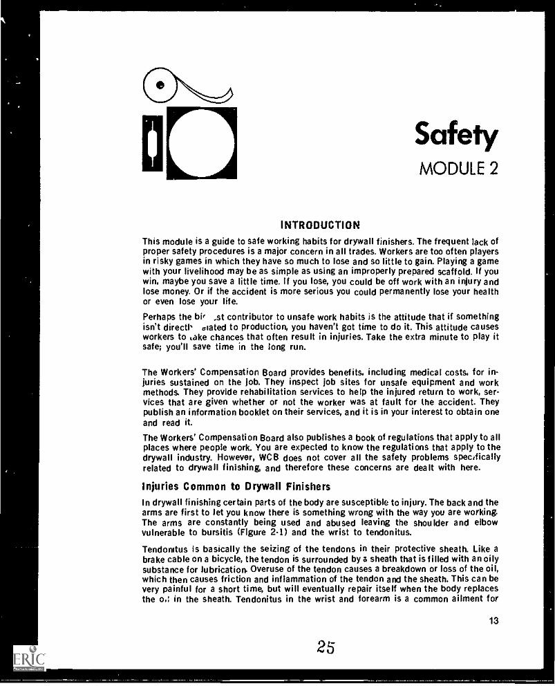
Injuries Common to Drywall FinishersIn drywall finishing certain parts of the body are susceptible to injury. The back and thearms are first to let you know there is something wrong with the way you are working.The arms are constantly being used and abused leaving the shoulder and elbowvulnerable to bursitis (Figure 2-1) and the wrist to tendonitus.
Tendonitus is basically the seizing of the tendons in their protective sheath. Like abrake cable on a bicycle, the tendon is surrounded by a sheath that is filled with an oilysubstance for lubrication. Overuse of the tendon causes a breakdown or loss of the oil,which then causes friction and inflammation of the tendon and the sheath. This can bevery painful for a short time, but will eventually repair itself when the body replacesthe o.: in the sheath. Tendonitus in the wrist and forearm is a common ailment for
25
13
Module 2
people new to the trade who have been coating nails all day.
Bursitis is a more serious injury because it affects the joints of the arm. The bursa is afluid-filled sac that creates a cushion or pad for the ligament to run over. With constantuse, the ligament may put enough pressure on the bursa so that the inner surfaces con-tact each other and start a fibrous growth within the bursa. This causes inflammationas the bursa loses its cushioning effect, Under extreme conditions, the body will sendother fluids into the bursa resulting in calcium deposits that must be surgicallyremoved. In most cases, heat and anti-inflammatory chugs will cure bursitis. Moreserious cases will require injections of cortisone (a lubricant), or hospitalization. Theinjections are a temporary solution, however, as the bursa will again lose its fluid andcollapse.
(1) A distended subacromial bursa. Slightmovement of the other structures, (2) collar-bone, (3) acromion, and (4) humerus, pinchthe inflamed bursa and cause excruciatingpain.
figure 2-1Bursitis in the Shoulder
Drywall finishers are also susceptible to back problems. Back problems are caused byoverreaching or applying pressure to the back when it is in awkward positions such ascan occur while operating a taping machine. The weight of an automatic taper or flatfinisher, plus the leverage that the handle creates, multiplies the stress on the back'sdiscs and ligaments. This can cause the discs to rupture and release fluid into thespinal column, creating pain in the lower back and legs. An injured disc will never healto its pre-injury state because scar tissue forms that reduces the flexibility of the disc.Afterwards, when pressure is put on the disc, it will burst more easily. Back injuries arelifetime injuries.The intention here is not to paint a bleak picture of injuries, but rather to make youaware that injuries are an occupational hazard and that you should give thought to yourworking techniques. By developing careful work habits you can prolong your workinglife as a drywall finisher.
14
26
Safety
Minimum Stress Trowelling TechniquesPulling a trowel causes stretching of the muscles and joints which sooner or later willcause your elbow and shoulder to hurt. Pushing a trowel, on the other hand, puts lessstress on arm muscles and joints. Therefore, use a pushing motion whenever possiblewhile trowelling (Figure 2-2).
Figure 2-2
Pullingincreases stress
on the bodyPushing is
less stressful
Also keep your arm close to your body to reduce strain. The further your arm is fromyour body the more stress is put on it.
Figure 2-3
........
Back and armunder stress
.....4,fElevating yourwork floor withstilts relievesstress on the
body
1
2715
Module 2
If you trowel above shoulder height, the tendency is to arch your back to put morepressure on the trowel. This puts more pressure not only on your arm, bc4144..1 on yourback (Figure 2-3). To avoid this stress elevate your position with s' `Its or scaffolls sothat you do not have to arch your back.
When trowelling near the floor, bend your knees instead of your kick. The same rein-ciples that apply to lifting also apply to trowelling.
Minimum Stress Techniques with Taping MachinesWhile taping machines considerably speed the taping process, they can shorten theworking life of drywall finishers. Muscles and joints are attuned to the length of thelimbs. Whan a taping machine is used, it extends the length of the arms and in so doingputs stress on the arm muscles and joints and on the back. Taping machines must beheld correctly with the body in the right position to minimize the stress.
Incorrect posiVonincreases stress
Correct position givesminimum stress
Figure 2-4
As discussed earlier drywall finishers are susceptible to elbow, shoulder, and backproblems. Although WCB does not sonsider the machines the selves a cause of theseinjuries, a good case can be made showing that improper techniques when using tapingmachines cause injuries that reduce working life.
One of the problems with machines is their speed. There is a tendency for the operatorto maintain the speed even in situations where the use of a machine is not feasible, forexample, where it is necessary to stretch or bend the back. While an automatic tapermay weigh only 15 kg when full, the force it exerts is multiplied the further it is usedfrom the body. Know the limitations of your body: do not exert needless, and ultimatelydamaging, strain on yourself.
16
28
Safety
Don't walk backwards with the automatic taper, as is common practise, twisting yourbody to see where you are walking. This puts strain on your back muscles, ligaments,and discs. A much better method is to turn your hips so that you walk forward with thetaper, pusing it at an angle parallel to the line formed by your hips and shoulders(Figure 2-4). Pushing a taping machine is easier on your body than pulling it.
When working above your head, try to keep your arms straight so that the force is trans-ferred through your skeletal structure to the floor. If you bend your limbs, the force istransferred to the joints, which were not meant to withstand such pressure. When usinga machine on horizontal joints, bend one arm and brace it against your body to putpressure on the machine. By doing this, no injurious pressure is transferred to your armjoints. Remember, continuous pressure on joints hastens wear on the joints. Don't useworking techniques that cause your body to wear out before its time.
Safe Practice with Stilts and ScaffoldsAny time you work on stilts or scaffolds there is a potential for injury. Therefore use ex-tra caution, and accept the fact that production is necessarily slower when working onthem. Also adhere to the following safe practices.
Preparing Stilts1. All straps must be secure and strong.2. The top of the leg support should fit just below the knee.3. The tube of the leg support should pass directly over the ankle bone.4. Foot plates should allow the shoe to fit snugly into the slit.5. On adjustable spring stilts, the spring should be adjusted so that walking finis
natural.6. Alt rubber pads must be secured to the stilts, and they must be clean and in good
condition.7. All nuts and bolts must be tight.8. All worn parts should be replaced.
Putting on Stilts1. Beginners may need to lean against a wall for support.2. Fasten the top straps first.3. Fasten the foot straps.Note This sequence will minimize the likelihood of a broken ankle should you fall
before the stilts are completely fastened.
Working on Stilts1. Make sure all floors are clean.2. Make sure all fixtures protruding from the floor are clearly marked.3. All safety railings must be elevated to prevent you from falling over them.4. Note all protrusions from ceilings.5. Note all ceilings that are lower than average.
17
29
Module 2
6. Insulate all live wires hanging from ceilir:Js.7. Stilts should be of a comfortable working height.8. Do not wear stilts on stairs, planks, or elevated work surfaces.9. The suggested maximum safe height for stilts is 60 cm.
Preparing Scaffolds1. The minimum dimension of the plank is 38 mm x 235 mm (nominal size).2. All planks should be of strong knot-free wood.3. Ensure a minimum of two planks per work floor.4. The maximum height of a free-standing scaffold is 3 times minimum base dimen-
sion.5. The maximum height for remaining on a moving scaffold is 2 times minimum base
dimension.6. The maximum height for remaining on a scaffold while moving it yourself is 1.5
times minimum base dimension.7. All cross braces and safety railings must be in place.8. All parts of the scaffold should be erected so there is no danger to other workers.9. The wheels should be a minimum of 12.7 cm diameter.
Working on Scaffolds1. If no guard rail is feasible and you are more than 3 m from the ground, a safety
rope should be worn.2. Tools and materials should be lifted to the work surface with a rope.3. Ladders, stilts, sawhorses, or other means of elevating yourself must not be used
on a scaffold.4. While on a scaffold that is being moved, keep a low profile.5. A scaffold should not be moved until everyone concerned is aware that it is about
to be moved.6. Let your co-worker on the scaffold know what you are about to do.
Constructing Safety Railings1. The minimum height of 3 safety rail is 1 m.2. Safety rails must be sturdy enough to restrain a fall.3. Elevator shafts, stairwells, and holes in floor:, or exterior walls should have safety
rails or be closed.4. Scaffolds and walk ways should conform to WCB regulations regarding safety
rails.
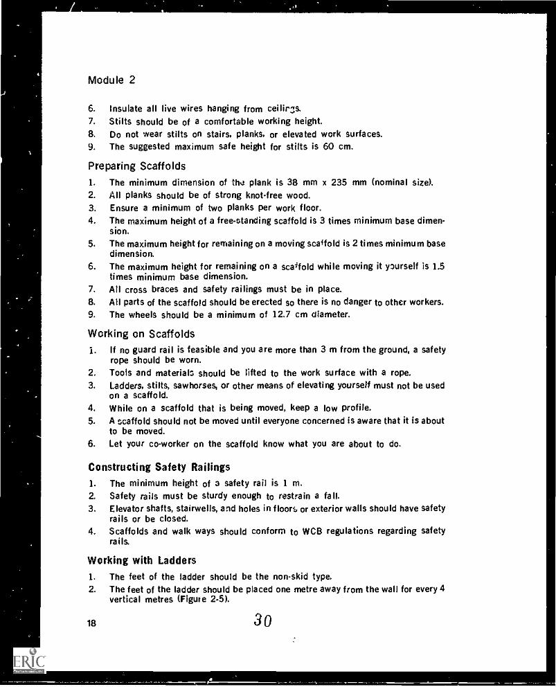
Working with Ladders1. The feet of the ladder should be the non-skid type.2. The feet of the ladder should be placed one metre away from the wall for every 4
vertical metres (Figure 2-5).
18 30
Safety
3. When a ladder leads to a landing, it should go in beyond the landing.4. Wooden ladders should not be painted.5. Always face a ladder when climbing up or down it.6. Watch for electrical hazards when carrying and placing a ladder.
Ladder extendsbeyond landing
Non-skidfeet
4 m
I1-1 m-I
Figure 2.5Ladder Safety
Safety Precautions with FloorsDrywall finishers spend their time on walls and ceilings, not on floors. There are,however, some minimal precautions that should be taken with floors:1. Protruding pipes should be shielded or made more visible.2. Holes such as heating vents should be covered when practical with material that
will support your weight.3, Scrap such as pieces of wire or pipe, paper, wallboard, plastic, cardboard should
be pushed aside where it is least likely to get in your way.4. Other trades' materials, if they are present, should be neatly piled so that they
can't be tripped over.5. Filler or water spills should be removed immediately.6. Pails and equipment should be kept out of the work path.
Electrical Equipment PrecautionsAll electrical equipment must have a grounding system a plastic double-insulatedhandle or a grounded plug. Asa drywall finisher, you will be working primarily with 110V conducted through a cold of three wires a black, a white and a green. The blackand the white wire: carry the electricity and the green one is the ground. At the maleend, the ground is connected t' a metal rod sunk into the ground outside the building,and any power running through this wire is dissipated into the earth. At the female end,
3119
r
I
I.
Module 2
the green wire is connected to the ground wire running from the tool casing. A short inthe wire will energize the casing of the tool. With the ground wire hooked up, the powerpasses harmlessly through the green wire. If the ground wire is not hooked up, the elec-tricity will take the only other route available through the person holding the tool. Ifyou are wearing good footwear that is dry and has no holes, you will feel only a tingle; ifyou are wearing poor footwear, you will feel a good "shot." The nervous system is anelectrical system and conducts electricity very well. A mild electrical shock can causetemporary paralysis of a muscle. A more serious shock can cause unconsciousness, inwhich case the victim should be rushed to a hospital.
Because the finisher works with electric drills and water when mixing filler, there is adanger of electrical shock. As a precaution, make sure that the drill is properly groun-ded or has a plastic double-insulated handle. Keep the floor around the mixing area dry,and do not leave the drill in the mix in a position that it can be knocked over. If youcome across a drill lying in a pool of water, unplug the drill before you pick it up. Stayout of the pool of water because it may be energized.
Triggers on drills have a tendency to stick in the "on" position. This can be dangerousespecially if you are mixing a thick mix. The pail may begin to spin or the drill may spinout of your hands and injure your wrists or legs. Make sure the trigger easily returns tothe "off" position. If not, have the drill repaired.
Some job sites have 220 V hook-ups for certain carpenter's tools. Some people try torun 220 V through a 110 V cord by eliminating the ground. If you hook up a 110 V toolto a 220 V power source, you are energizing the casing of the tool. Since there is noground, if a short occurs, you will be on the receiving end of a 240 V jolt. To be safe,use only the cord; supplied by your employer or yourself.
On most large job sites, a laser level is used. A laser beam is a high energy beam oflight. The level is perfectly safe as long as you do not look directly into the beam.However, prolonged viewing directly at a laser beam can cause damage to the retina.
Pressurized Equipment PrecautionsA drywall finisher works with both air pressure and hydraulic pressure. Two majorsafety concerns with pressure are:1. The point where the pressure is released should be properly shielded and safely
controlled.2. The hoses carrying the pressure shoula be in good shape and have sound con-
nections.
Never point a pressurized hose at yourself or anyone else. Follow the safety recom-mendations In the manufacturer's operator's manual, and do not op.:.rate the equipmentunless you have proper training.
Dust ProtectionThe body has a natural protective system to screen out dust. The lungs are lined withtiny hair-like cells called cilia, and a sticky substance called mucus. The mucus actslike flypaper as it catches dust particles that enter the lungs. The cilia are constantly inmotion, and pass the particles out of the lungs. However, very fine fibres such asasbestos fibres are able to bypass this protective system and penetrate the part of thelungs where the oxygen enters the blood. The lung tissue here is very soft and easily
20
32
Safety
punctured by the sharp needle -like asbestos fibres. Continued breathing of asbestosfibres can cause asbestosis, a serious disease of the lungs. It can also :.cruse lung can.cer.
In the past drywall filler contained asbestos, but now fillers, by law, must be asbestos-free. The material substituted for asbestos is attapulgite clay (Minigel and Attagell aretwo trade names for attapulgite clay). To date no hazard nas been reported with at-tapulgite clay. However, it took medical science 25 years to discover that asbestos washarmful, so it's better to be safe and wear a mask.
Masks should be worn in the following situations. mixing powdered fillers; sanding allfillers; cleaning floors; spraying ceilings, The worst of these is mixing powdered fillers.Thus pre-mixed tillers have an advantage since they require no dry mixing.
The type of mask you use is very important. It must be approved for pneumoconiosis-producing dusts. This approval will be found on the box, not on the mask, and will con-sist of the letters NIOSH, MESA, or U.S. Bureau of Mines, and a series of approval num-bers. Contact a safety supply company and ask them to show you some approvedmasks. Approved disposable masks are also available. All masks must have two strapsto ensure a tight fit to your skin. To be most effective, there should be no facial hair inthe area that the mask will contact.
Another dust protective practice is to change your work cloths before leaving the job.This way you won't be carrying the dust home with you every night.
if you develop a skin rash on your shoulders and down your back and arms, see yourdoctor and let him know that you work with filling compounds. Also, it is a good idea tohave regular medical checkups and chest X-rays. This will enable your doctor to knowwhen there is a change in the health of your lungs. If you develop a lung disease, theseX-rays could help to prove to the Workeos' Compensation Board that the disease is job-related and therefore is subject to compensation.
Eye ProtectionTo protect your eyes, invest in a reliable pair of safety glasses. They are especially help-ful when texturing ceilings. They get dirty and you may have to stop to clean them, butwhen you do you can see how much material you have prevented from getting into youreyes.
Noxious Fume ProtectionNoxious fumes are present when using some V, the spevial sealers for sealing off wateror smoke stains. The fumes from solvents enter the bloodstream and cause dizziness.Any material that causes dizziness is affecting your brain cells. Filters that filter outthe toxic fumes can be bought to fit the type of rubber masks that have screw -oncanisters. In addition, it is wise to have the best ventilation possible when working withtoxic fumes, even when wearing a mask.
Ventilation is also important when using gasoline engines to power equipment or whenusing combustible fuels for heating. Without venting, the amount of carbon monoxidein the air can build up and cause nausea, drowiness, and under extreme conditions, un-consciousness or death. The heater or engine should be vented to the outside; anelevator shalt should not be used because it will disperse the carbon monoxidethroughout the building.
21
.4
Module 2
Hearing ProtectionVery little attention has been given to the noise level on some drywall finishing jobs.The texture machines are especially noisy. The noise from the gasoline engine, thepump, and textur. wand, when combined with the noise of the drills used for mixing,may cause a hearing loss. Always wear ear protection when mixing the material oroperating the wand.
Head Protection
While it is not common for drywall finishers to wear a hard hat when working, WCBregulations require one to be worn whenever there is a danger of falling material. Thismeans that a hard hat is required when working below a scaffold, and when entering orleaving some job sites.
SUMMARY
Know all the Workers' Compensation Board regulations that apply to drywallfinishing.Make sure the floors are safe to work on.Make sure all stairwells have railings, and that safety rails are in place aroundelevator shafts and holes in the floor.Check your stilts regularly and replace worn parts.Make sure your scaffold conforms to Workers' Compensation Board regulations.To minimize stress on your body and the possibility of getting tendonitis, bursitis,or back trouble, use good working techniques.Always wear a mask when dust is present.Vent to the outside all gasoline engines. Provide adequate ventilation for keroseneheaters.
Always wear safety glasses when texturing.Always wear ear protection when working with large texture machines.Observe safety precaution with pressurized equipment and electrical equipment.
EXERCISE
1. What is the acceptable diameter of wheels used for scaffolds?2. What are the height restrictions for scaffolds?3. Is your present mask approved for pneumoconiosis- producing dusts?4. What is the role of the Workers' Compensation Board?5. What are three strainrelaied injuries common to drywall finishers?6. What are two potential hazards with electrical mixers for fillers?7. When would you be required to wear a hard hat?8. What is the main cause of Injury when working with taping and filling machines?9. What are four techniques for minimizing stress when trowelling?
22
34,
On Applying BeadMODULE 3
INTRODUCTION
There are many types of beads and several methods of attaching them. Basically, theyall t.erve the same purpose finishing and protecting the corners of wallboard. Theyprovide a smooth, straight, unbroken edge that is then tilled to blend into the wallmaking a uniform surface. Beads tall into two categories: corner beads and edge trims.Each has a specific use; they are not interchangeable.
All beads have two parts: the finishing edge, or nose, and the flange (Figure 3-1). Thefinishing edge is the part that shows after the bead has been filled and sanded. It issmooth and rounded to provide a smooth finished surface that filler does not stick to.The flange is the part that attaches to the wall and holds the filler on the bead. It isknurled to provide a keyed surface for filler and has holes punched in it at intervals forattaching it to the wallboard.
Finishing edgeor nose --....
85°,,,,--- Flange
Figure 3-1Bead
This module describes the types of beads and trims, their advantages and disad-vantages, where they should be used, and how they are cut and applied.
Beads
The five corner beads most often used in the industry today are: metal corner bead,veneer bead, paper corner bead, screen bead and flexible or roll-on bead. Paper, screen,and flexible corner bead are called glue-on bead because they are attached with filler.Metal corner bead and veneer bead are attached with fasteners.
23
35
Module 3
Figure 3-2Metal Bead
28.6 mm
Metal Corner BeadMetal corner bead (Figure 3.2) is made from electrogalvanized metal to preventrusting under normal use and filling conditions. Fasteners are applied to the flange ofthe bead to hold it in place. Metal bead can be nailed, screwed, or clinched. Nailing andscrewing attach the bead to the framing members se that it will not pull loose. Clinch-ing attaches the bead to the surface of the wallboard. Teeth of a tool called a clinchercut the flange of the bead and force the tangs of metal into the core of the board.
....._... .41. Asonar...sow'
...-40rAPra"..0"- -,,,./Av.a1P4050,;0....,A0/41/4/4114111'40- .-.- --- ,,,,,pr"' .0.4.4....441104P/Go' ----""- - ,04., ...... A." aW/11.40.
.......".- ...,iip:-. AI.
igriirAdrArArAPAP/PA.411.AVAI.APPAPADWAP:4141PWAP-...-APY
AptgrarilwatorAir4101411/411:AWAIrAPAIKAPAP
Figure 3.3Veneer Bead
3.2 mm
Mini or Veneer BeadMini bead, also known as veneer bead (Figure 3.3), is the best bead to use when a corner must be plumbed or straightened. The metal mesh can be fastened at any pointalong the flange without twisting the bead. Veneer bead is usually stapled to thewallboard.
24
36
Applying Bead
Stapling does not provide a solid attachment since the bead is independent of theframing members. The addition of the filler provides a more positive bond because thefiller flows through the mesh and adheres to the surface of the wallboard, creating asandwich effect. This type of bead perhaps is the strongest and best wearing of themetal corner beads.
One disadvantage common to all metal corner beads is that a positive bond t.., the sur-face is not formed along the entire length of the bead. Therefore the bead could beloose in spots, causing the flange to lift from the wall surface and create cracks if thebead is bumped after it is filled. Another disadvantage is that the smooth, round edgeof the bead does not provide a well-keyed surface for the adhesion of paint, causing thepaint to chip off on contact. Despite these drawbacks, metal beads are the most com-monly used because of speed of application.
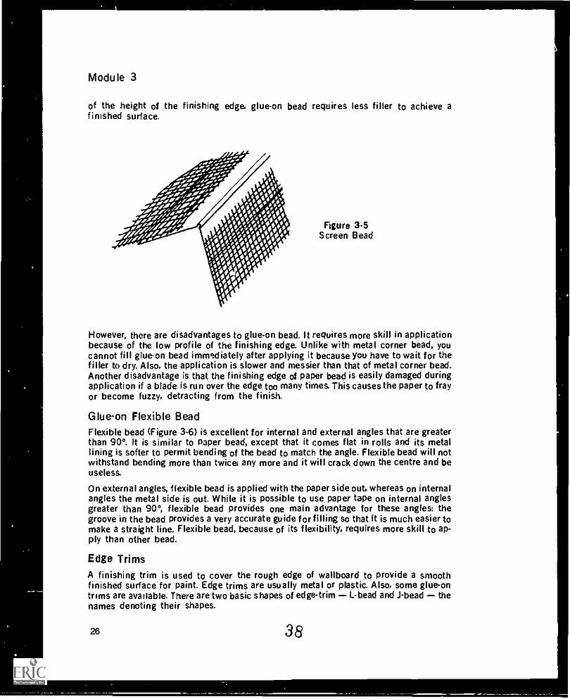
Glue-on Paper Bead and Screen Bead
Glue-on paper bead (Figure 3-4) forms the most positive bond to the wallboard. It isglued to the wallboard with taping filler. The paper of the bead is the same as that usedfor joint tape. The cross-fibres of the tape provide strength in all directions and enablethe filler to penetrate the tape and form a strong bond. Paper bead has a partial metallining for rigidity.
. .
. .I
Figure 3.4Paper Bead
Screen bead (Figure 3.3) is also glued on. The screen allows filler to flow through andcreate a strong bond. Screen bead has a metal finishing edge like metal corner bead.
Because taping filler is used to adhere glue-on bead, the gap is filled between the metalof the bead and the wallboard providing a solid backing for the finished edge. Beingmore solid, glueon bead withstands much more abuse than the metal bead, which hasa hollow space behind the finished edge. The paper bead has especially good paintadhesion and will withstand bumps and knocks without chipping. Glue-on bead can beapplied to any wallboard surface whether there is backing or not. It is not affected bythe movement of the framing members and is bonded along the entire length. Because
3725
Module 3
of the height of the finishing edge, glue-on bead requires less filler to achieve afinished surface.
Figure 3-5Screen Bead
However, there are disadvantages to glue-on bead. It requires more skill in applicationbecause of the low profile of the finishing edge. Unlike with metal corner bead, youcannot fill glue-on bead immediately after applying it because you have to wait for thefiller to dry. Also, the application is slower and messier than that of metal corner bead.Another disadvantage is that the finishing edge of paper bead is easily damaged duringapplication if a blade is run over the edge too many times. This causes the paper to frayor become fuzzy, detracting from the finish.
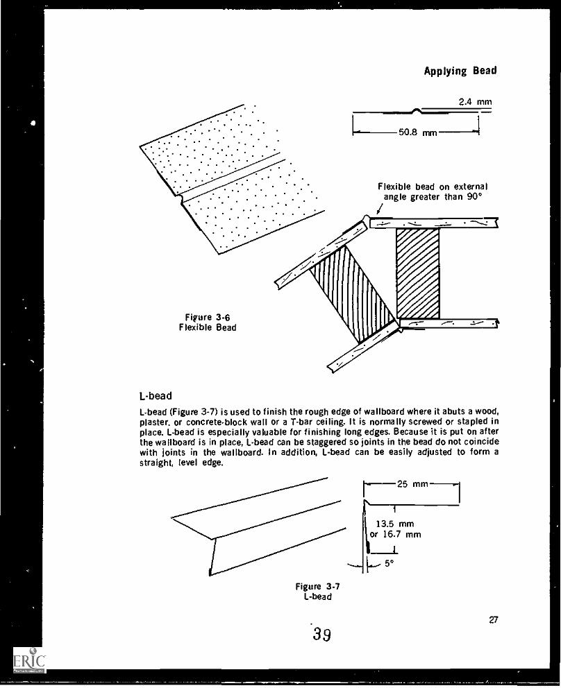
Glue-on Flexible BeadFlexible bead (Figure 3-6) is excellent for internal and external angles that are greaterthan 90°. It is similar to Paper bead, except that it comes flat in rolls and its metallining is softer to permit bending of the bead to match the angle. Flexible bead will notwithstand bending more than twice; any more and it will crack down the centre and beuseless,
On external angles, flexible bead is applied with the paper side out, whereas on internalangles the metal side is out. While it is possible to use paper tape on internal anglesgreater than 90°, flexible bead provides one main advantage for these angles: thegroove in the bead provides a very accurate guide for filling so that it is much easier tomake a straight line. Flexible bead, because of its flexibility, requires more skill to ap-ply than other bead.
Edge TrimsA finishing trim is used to cover the rough edge of wallboard to provide a smoothfinished surface for paint. Edge trims are usually metal or plastic. Also, some glue-ontrims are avarlabie. There are two basic shapes of edge-trim L-bead and J-bead thenames denoting their shapes.
26 38
a
Applying Bead
2.4 mm--.es..1-ff-- 50.8 mm ---".1
Flexible bead on externalangle greater than 90°
Figure 3-6Flexible Bead
L-bead
L-bead (Figure 3-7) is used to finish the rough edge of wallboard where it abuts a wood,plaster. or concrete-block wall or a T-bar ceiling. It is normally screwed or stapled inplace. L-bead is especially valuable for finishing long edges. Because it is put on afterthe wallboard is in place, I- -bead can be staggered so joints in the bead do not coincidewith joints in the wallboard. In addition, L-bead can be easily adjusted to form astraight, level edge.
Figure 3-7I- -bead
39
r_25r 1
\I
13.5 mmor 16.7 mm
"--....i...
_I_
27
Module 3
J-bead
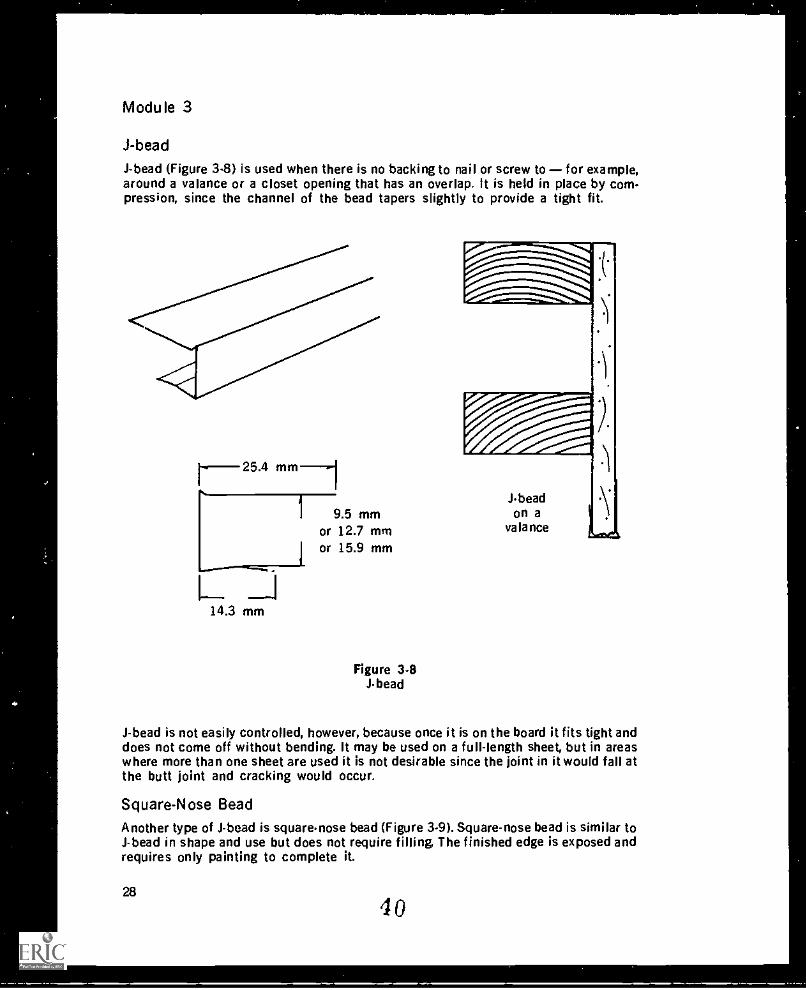
J-bead (Figure 3.8) is used when there is no backing to nail or screw to for example,around a valance or a closet opening that has an overlap. It is held in place by com-pression, since the channel of the bead tapers slightly to provide a tight fit.
r25.4 mm-1
L. _114.3 mm
1 9.5 mmor 12.7 mmor 15.9 mm
Figure 3-8Jbead
-"I'141%.,
Jbead
\lon avalance
J-bead is not easily controlled, however, because once it is on the board it fits tight anddoes not come off without bending. It may be used on a full-length sheet, but in areaswhere more than one sheet are used it is not desirable since the joint in it would fall atthe butt joint and cracking would occur.
Square-Nose Bead
Another type of J-bead is square-nose bead (Figure 3-9). Square-nose bead is similar toJ-bead in shape and use but does not require filling. The finished edge is exposed andrequires only painting to complete it.
28
40
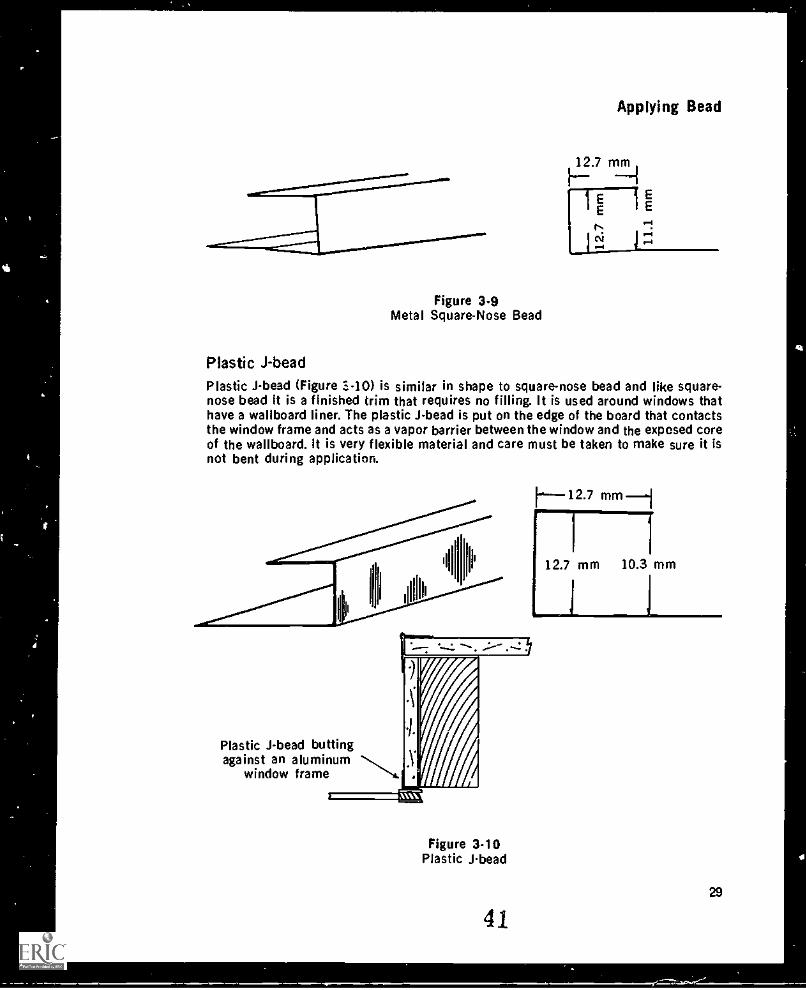
Figure 3.9Metal Square-Nose Bead
Applying Bead
Plastic JbeadPlastic J-bead (Figure .1.-10) is similar in shape to square-nose bead and like square-nose bead it is a finished trim that requires no filling. It is used around windows thathave a wallboard liner. The plastic J-bead is put on the edge of the board that contactsthe window frame and acts as a vapor barrier between the window and the exposed coreof the wallboard. It is very flexible material and care must be taken to make sure it isnot bent during application.
12.7 mm
12.7 mm 10.3 mm
Plastic J-bead buttingagainst an aluminum
window frame
Figure 3-10Plastic J-bead
4129
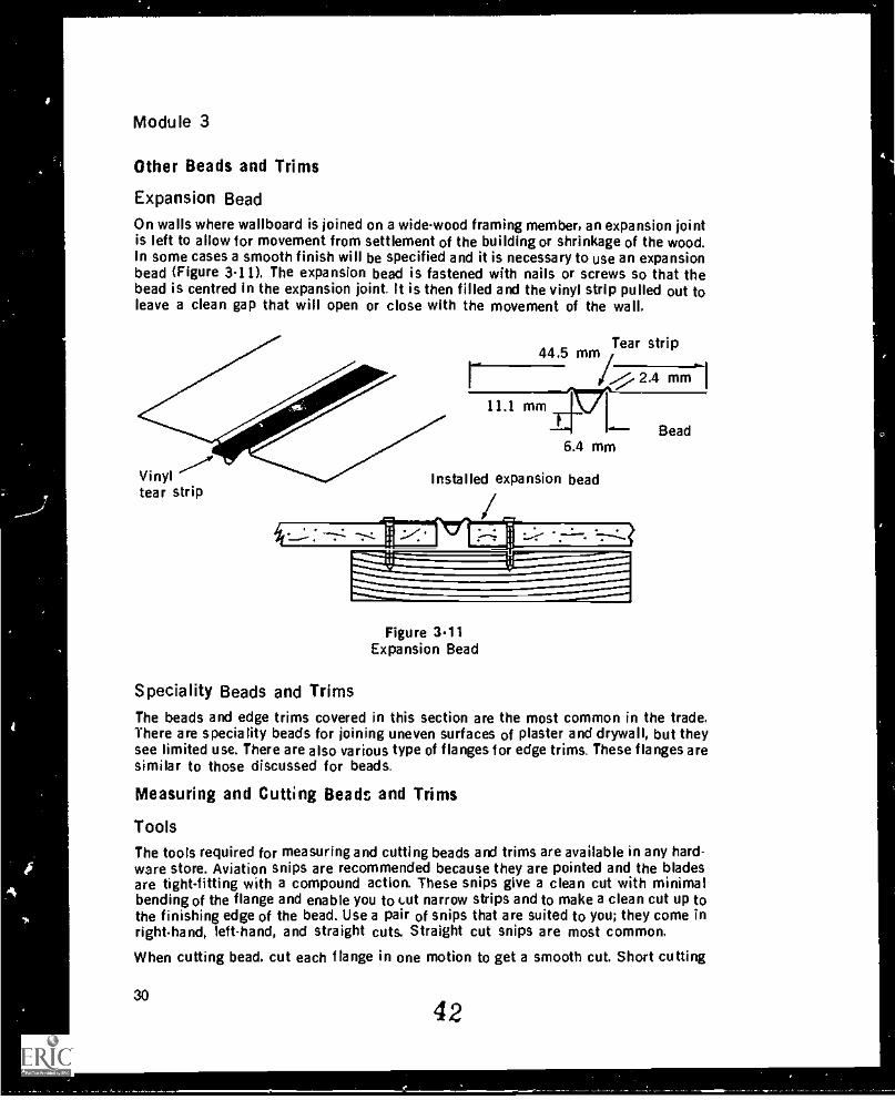
Module 3
Other Beads and Trims
Expansion Bead
On walls where wallboard is joined on a wide-wood framing member, an expansion jointis left to allow for movement from settlement of the building or shrinkage of the wood.In some cases a smooth finish will be specified and it is necessary to use an expansionbead (Figure 3-11). The expansion bead is fastened with nails or screws so that thebead is centred in the expansion joint. It is then filled and the vinyl strip pulled out toleave a clean gap that will open or close with the movement of the wall.
Vinyltear strip
44.5 mm ,Tearstrip
#1/71 mmi11.1 mm
Bead6.4 mm
Installed expansion bead
Figure 3.11Expansion Bead
Speciality Beads and TrimsThe beads and edge trims covered in this section are the most common in the trade.There are speciality beads for joining uneven surfaces of plaster and drywall, but theysee limited use. There are also various type of flanges for edge trims. These flanges aresimilar to those discussed for beads.
Measuring and Cutting Beads and Trims
ToolsThe tools required for measuring and cutting beads and trims are available in any hard-ware store. Aviation snips are recommended because they are pointed and the bladesare tight-fitting with a compound action. These snips give a clean cut with minimalbending of the flange and enable you to tut narrow strips and to make a clean cut up tothe finishing edge of the bead. Use a pair of snips that are suited to you; they come inright-hand, Ieft-hand, and straight cuts. Straight cut snips are most common.
When cutting bead. cut each flange in one motion to get a smooth cut. Short cutting
3042
1.7
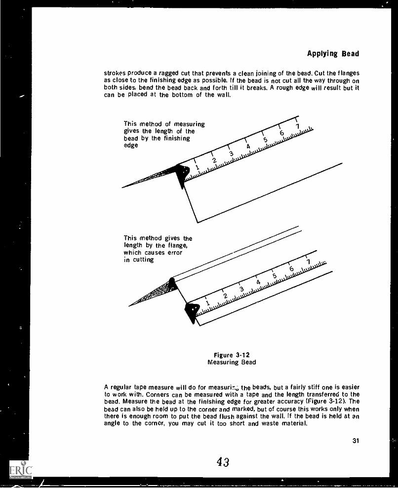
Applying Bead
strokes produce a ragged cut that prevents a clean joining of the bead. Cut the flangesas close to the finishing edge as possible. If the bead is not cut all the way through onboth sides, bend the bead back and forth till it breaks. A rough edge will result but itcan be placed at the bottom of the wall.
This method of measuringgives the length of thebead by the finishingedge
This method gives thelength by the flange,which causes errorin cutting
Figure 3-12Measuring Bead
A regular tape measure will do for measurinc; the beads, but a fairly stiff one is easierto work with. Corners can be measured with a tape and the length transferred to thebead. Measure the bead at the finishing edge for greater accuracy (Figure 3-12). Thebead can also be held up to the corner and marked, but of course this works only whenthere is enough room to put the bead flush against the wall. If the bead is held at enangle to the corner, you may cut it too short and waste material.
31
43
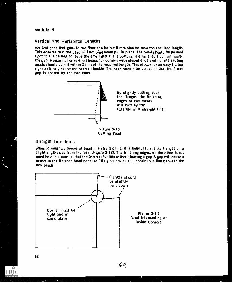
Module 3
Vertical and Horizontal LengthsVertical bead that goes to the floor can be cut 5 mm shorter than the required length.This ensures that the bead will not bind when put in place. The bead should be pushedtight to the ceiling to leave the small gap at the bottom. The finished floor will coverthe gap. Horizontal or vertical beads for corners with closed ends and no intersectingbeads should be cut within 2 mm of the required length. This allows for an easy fit; tootight a fit may cause the bead to buckle. The bead should be placed so that the 2 mmgap is shared by the two ends.
By slightly cutting backthe flanges, the finishingedges of two beadswill butt tightlytogether in a straight line .
Figure 3-13Cutting Bead
Straight Line JoinsWhen Joining two pieces of bead :n a straight line, it is helpful to cut the flanges on aslight angle away from the joint (Figure 3-13). The finishing edges, on the other hand,must be cut square so that the two beads align without leaving a gap. A gap will cause adefect in the finished bead because filling cannot make a continuous line between thetwo beads.
Corner must betight and insame plane
Flanges shouldbe slightlybent down
32
44
Figure 3-14B-ad Intersecting at
Inside Corners
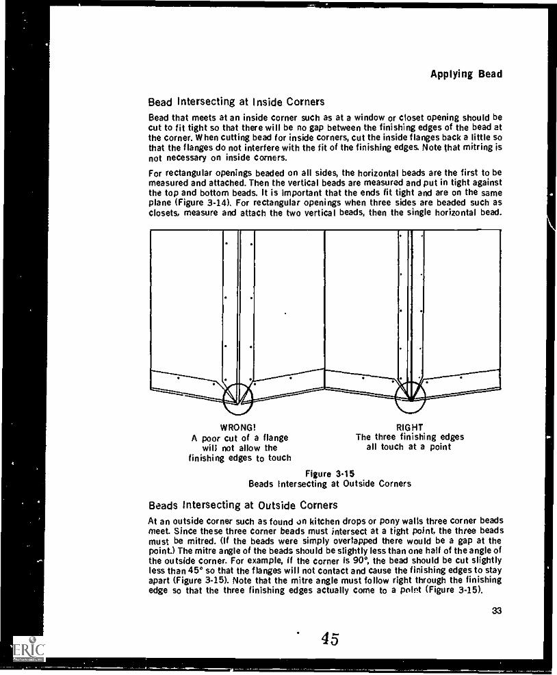
Applying Bead
Bead intersecting at Inside CornersBead that meets at an inside corner such as at a window or closet opening should becut to fit tight so that there will be no gap between the finishing edges of the bead atthe corner. When cutting bead for inside corners, cut the inside flanges back a little sothat the flanges do not interfere with the fit of the finishing edges. Note that mitring isnot necessary on inside corners.
For rectangular openings beaded on all sides, the horizontal beads are the first to bemeasured and attached. Then the vertical beads are measured and put in tight againstthe top and bottom beads. It is important that the ends fit tight and are on the sameplane (Figure 3-14). For rectangular openings when three sides are beaded such asclosets, measure and attach the two vertical beads, then the single horizontal bead.
WRONG!A poor cut of a flange
will not allow thefinishing edges to touch
Figure 3.15Beads Intersecting at Outside Corners
RIGHTThe three finishing edges
all touch at a point
Beads Intersecting at Outside CornersAt an outside corner such as found on kitchen drops or pony walls three corner beadsmeet. Since these three corner beads must intersect at a tight point, the three beadsmust be mitred. (if the beads were simply overlapped there would be a gap at thepoint.) The mitre angle of the beads should be slightly less than one half of the angle ofthe outside corner. For example, if the corner is 90°, the bead should be cut slightlyless than 45° so that the flanges will not contact and cause the finishing edges to stayapart (Figure 3-15). Note that the mitre angle must follow right through the finishingedge so that the three finishing edges actually come to a point (Figure 3-15).
45
33
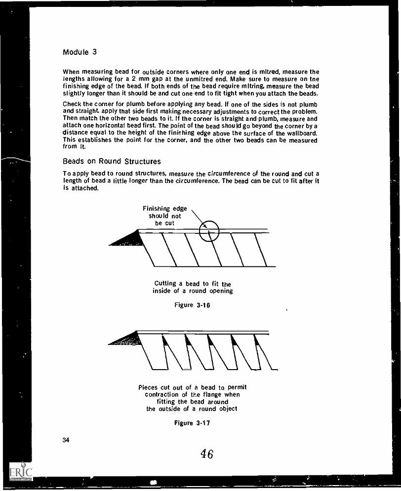
When measuring bead for outside corners where only one end is mitred, measure thelengths allowing for a 2 mm gap at the unmitred end. Make sure to measure on tnefinishing edge of the bead. If both ends of the bead require mitring, measure the beadslightly longer than it should be and cut one end to fit tight when you attach the beads.
Check the corner for plumb before applying any bead. If one of the sides is not plumband straight, apply that side first making necessary adjustments to correct the problem.Then match the other two beads to it. If the corner is straight and plumb, measure andattach one horizontal bead first. The point of the bead should go beyond the corner by adistance equal to the height of the finishing edge above the surface of the wallboard.This establishes the point for the corner, and the other two beads can be measuredfrom it.
To apply bead to round structures, measure the circumference of the round and cut alength of bead a little longer than the circumference. The bead can be cut to fit after itis attached.
Cutting a bead to fit theinside of a round opening
Pieces cut out of a bead to permitcontraction of the flange when
fitting the bead aroundthe outside of a round object
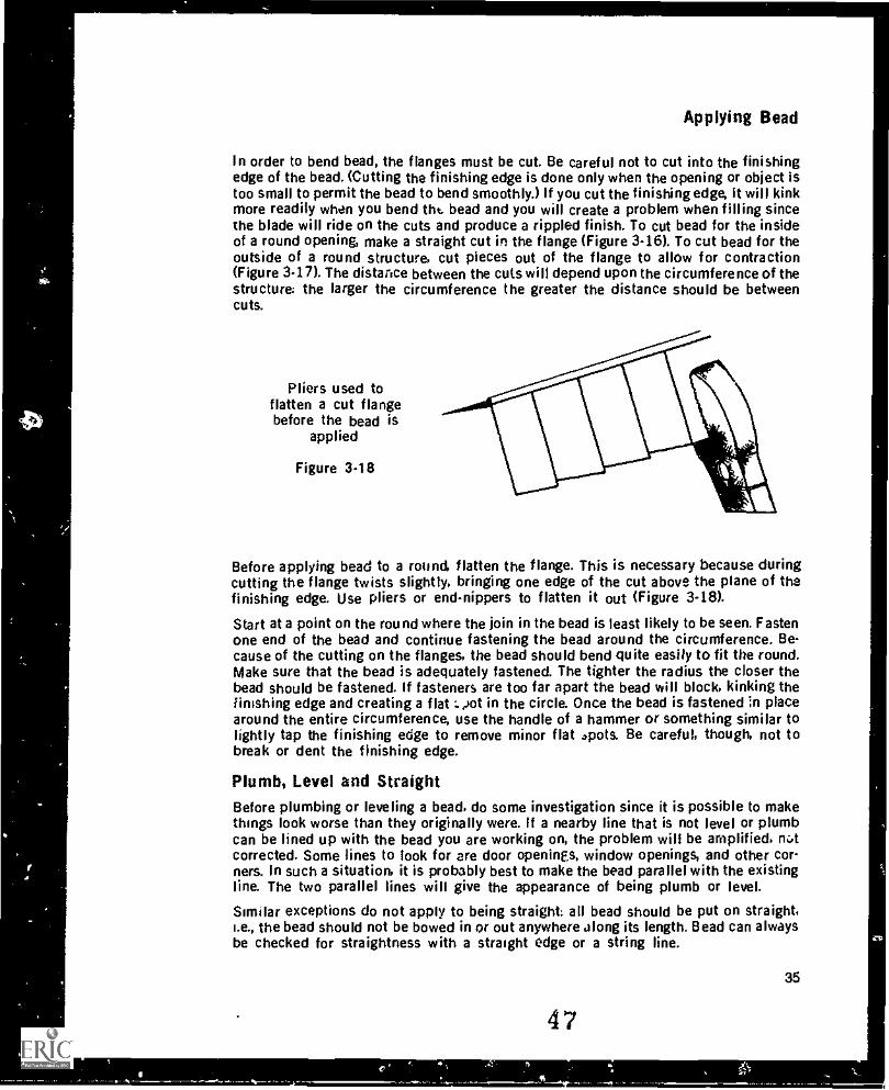
Applying Bead
In order to bend bead, the flanges must be cut. Be careful not to cut into the finishingedge of the bead. (Cutting the finishing edge is done only when the opening or object istoo small to permit the bead to bend smoothly.) If you cut the finishing edge, it will kinkmore readily when you bend tht bead and you will create a problem when filling sincethe blade will ride on the cuts and produce a rippled finish. To cut bead for the insideof a round opening, make a straight cut in the flange (Figure 3-16). To cut bead for theoutside of a round structure, cut pieces out of the flange to allow for contraction(Figure 3-17). The distance between the cuts will depend upon the circumference of thestructure: the larger the circumference the greater the distance should be betweencuts.
Pliers used toflatten a cut flangebefore the bead is
applied
Figure 3-18
Before applying bead to a round flatten the flange. This is necessary because duringcutting the flange twists slightly, bringing one edge of the cut above the plane of thefinishing edge. Use pliers or end-nippers to flatten it out (Figure 3-18).
Start at a point on the round where the join in the bead is least likely to be seen. Fastenone end of the bead and continue fastening the bead around the circumference. Be-cause of the cutting on the flanges, the bead should bend quite easily to fit the round.Make sure that the bead is adequately fastened. The tighter the radius the closer thebead should be fastened. If fasteners are too far apart the bead will block, kinking thefinishing edge and creating a flat :.4.)ot in the circle. Once the bead is fastened in placearound the entire circumference, use the handle of a hammer or something similar tolightly tap the finishing edge to remove minor flat *pots. Be careful, though, not tobreak or dent the finishing edge.
Plumb, Level and StraightBefore plumbing or leveling a bead, do some investigation since it is possible to makethings look worse than they originally were. If a nearby line that is not level or plumbcan be lined up with the bead you are working on, the problem will be amplified, notcorrected. Some lines to look for are door openings, window openings, and other cor-ners. In such a situation, it is probably best to make the bead parallel with the existingline. The two parallel lines will give the appearance of being plumb or level.
Similar exceptions do not apply to being straight: all bead should be put on straight,i.e., the bead should not be bowed in or out anywhere along its length. Bead can alwaysbe checked for straightness with a straight edge or a string line.
47
35
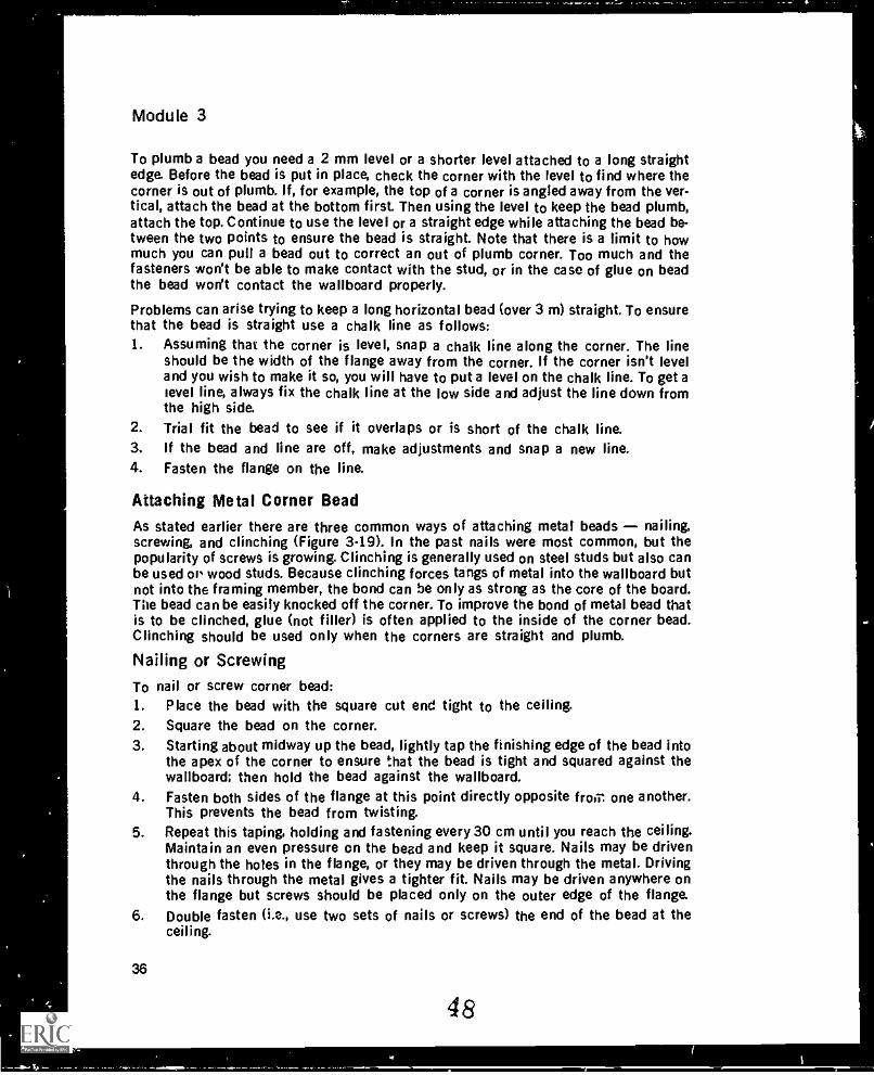
Module 3
To plumb a bead you need a 2 mm level or a shorter level attached to a long straightedge Before the bead is put in place, check the corner with the level to find where thecorner is out of plumb. If, for example, the top of a corner is angled away from the ver-tical, attach the bead at the bottom first. Then using the level to keep the bead plumb,attach the top. Continue to use the level or a straight edge while attaching the bead be-tween the two points to ensure the bead is straight. Note that there is a limit to howmuch you can pull a bead out to correct an out of plumb corner. Too much and thefasteners won't be able to make contact with the stud, or in the case of glue on beadthe bead won't contact the wallboard properly.
Problems can arise trying to keep a long horizontal bead (over 3 m) straight. To ensurethat the bead is straight use a chalk line as follows:1. Assuming that the corner is level, snap a chalk line along the corner. The line
should be the width of the flange away from the corner. If the corner isn't leveland you wish to make it so, you will have to put a level on the chalk line. To get alevel line, always fix the chalk line at the low side and adjust the line down fromthe high side.
2. Trial fit the bead to see if it overlaps or is short of the chalk line.3. If the bead and line are off, make adjustments and snap a new line.4. Fasten the flange on the line.
Attaching Metal Corner BeadAs stated earlier there are three common ways of attaching metal beads nailing,screwing, and clinching (Figure 3-19). In the past nails were most common, but thepopularity of screws is growing. Clinching is generally used on steel studs but also canbe used oi, wood studs. Because clinching forces tangs of metal into the wallboard butnot into the framing member, the bond can he only as strong as the core of the board.The bead can be easily knocked off the corner. To improve the bond of metal bead thatis to be clinched, glue (not filler) is often applied to the inside of the corner bead.Clinching should be used only when the corners are straight and plumb.
Nailing or ScrewingTo nail or screw corner bead:1. Place the bead with the square cut end tight to the ceiling.2. Square the bead on the corner.3. Starting about midway up the bead, lightly tap the finishing edge of the bead into
the apex of the corner to ensure that the bead is tight and squared against thewallboard; then hold the bead against the wallboard.
4. Fasten both sides of the flange at this point directly opposite fro one another.This prevents the bead from twisting.
5. Repeat this taping, holding and fastening every 30 cm until you reach the ceiling.Maintain an even pressure on the bead and keep it square. Nails may be driventhrough the holes in the flange, or they may be driven through the metal. Drivingthe nails through the metal gives a tighter fit. Nails may be driven anywhere onthe flange but screws should be placed only on the outer edge of the flange.
6. Double fasten (i.e., use two sets of nails or screws) the end of the bead at theceiling.
36
48
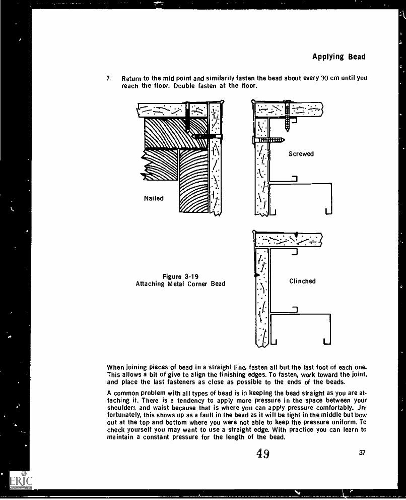
Applying Bead
7. Return to the mid point and similarily fasten the bead about every 30 cm until youreach the floor. Double fasten at the floor.
Nailed
Figure 3-19Attaching Metal Corner Bead
When joining pieces of bead in a straight line, fasten all but the last foot of each one.This allows a bit of give to align the finishing edges. To fasten, work toward the joint,and place the last fasteners as close as possible to the ends of the beads.
A common problem with all types of bead is in keeping the bead straight as you are at-taching it. There is a tendency to apply more pressure in the space between yourshouldert and waist because that is where you can apply pressure comfortably. in-fortunately, this shows up as a fault in the bead as it will be tight in the middle but bowout at the top and bottom where you were not able to keep the pressure uniform. Tocheck yourself you may want to use a straight edge. With practice you can learn tomaintain a constant pressure for the length of the bead.
49 37
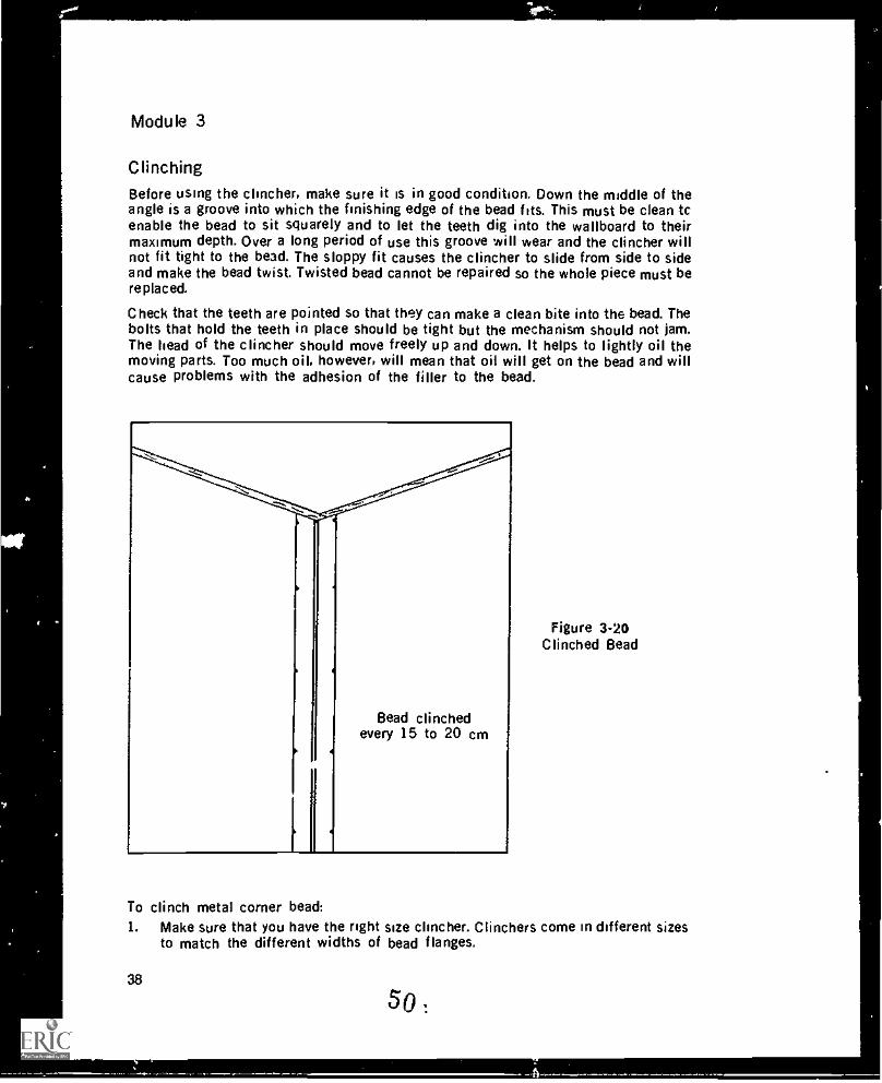
Module 3
ClinchingBefore using the clincher, make sure it is in good condition. Down the middle of theangle is a groove into which the finishing edge of the bead fits. This must be clean tcenable the bead to sit squarely and to let the teeth dig into the wallboard to theirmaximum depth. Over a long period of use this groove will wear and the clincher willnot fit tight to the bead. The sloppy fit causes the clincher to slide from side to sideand make the bead twist. Twisted bead cannot be repaired so the whole piece must bereplaced.
Check that the teeth are pointed so that they can make a clean bite into the bead. Thebolts that hold the teeth in place Should be tight but the mechanism should not jam.The head of the clincher should move freely up and down. It helps to lightly oil themoving parts. Too much oil, however, will mean that oil will get on the bead and willcause problems with the adhesion of the filler to the bead.
Figure 3-20Clinched Bead
Bead clinchedevery 15 to 20 cm
To clinch metal corner bead:1. Make sure that you have the right size clincher. Clinchers come in different sizes
to match the different widths of bead flanges.
38
so
Applying Bead
2. Start at about the mid point of the length of the bead.3. Plz.ce the clincher against the bead and tap the body of the clincher with a rubber
mallet to push the bead tight and square against the wallboard.4. Strike the head of the clincher with the mallet. Check to see that the teeth have
dug in about 3 mm; if not, strike the head again. Don't strike the clincher too hardas you can damage the finishing edge of the bead.
5. Move the clincher towards the ceiling striking the head every 15 cm to 20 cm(Figure 3-20). Maintain an even pressure on the bead and keep it square. Avoidhitting nails or screws with the teeth of the clincher because you may damage theteeth.
6. Clinch the bead about 3 cm from the ceiling.7. Return to the mid point and similarly clinch the bead every 15 cm to 20 cm until
you reach the floor. Again clinch about 3 cm from the end of the bead.
The 3 cm from the ends of the bead also app'' when joining bead. This allows you towatch the alignment of the two heads and preie the clincher from drawing the endsof the bead down.
Stapling Veneer Bead
Staples are not recommended for fastening ordinary metal bead because they rannotbe driven in far enough to securely attach the bead. Also, the finishing edge of ...dtalbead is not raised enough to clear the staples, and this would cause the trowel to con-tact the staples when filling.
Veneer bead, on the other hand, has a mesh flange that allows filler to bind the bead tothe wall. Staples are used to hold this bead in place for filling. The staples should beplaced 15 cm to 20 cm apart. The finishing edge of veneer bead is raised enough sothat a trowel can clear the staples.
As already mentioned the main use of veneer or mini bead is to straighten bowed or outof Plumb corners. To attach mini head:1. Place the bead tight to the ceiling.2. For bowed in corners staple both ends of the bead. For bowed out corners staple
at the furthest point out on the bow. For out of plumb corners staple at the endthat is angled out.
3. Adjust the finishing edge to a straight edge and level to ensure that the bead isstraight and plumb.
4. Staple the sides of the flange directly opposite each other every 15 cm to 20 cm.
Attaching Glue-On Beads (Paper, Screen and Flexible Corner Beads)Glue-on beads are more difficult to apply than metal beads. There are many factors thatinfluence the attaching of the bead such as drying conditions, the bonding capability offiller, the bond of the paper tape to the metal of the bead, and the skill of the ap-plicator.
There are three main methods of applying glue-on bead. pan and knife, hopper, and cor-ner tool and roller. All three methods can be used for applying paper or screen cornerbead, but flexible bead should be applied only by the knife and pan method. A 15 cm
39
51
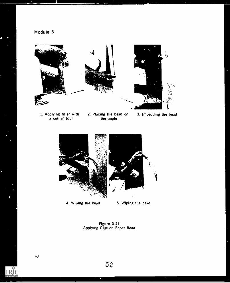
Module 3
40
1. Applying filler with 2. Placing the bead on 3. Imbedding the beada corner tool
.6
the angle
4. Wining the bead 5. Wiping the bead
Figure 3.21Applying Glue-on Paper Bead
52
Applying Bead
knife should be used when applying beads by hand. A general rule is to use the handmethod when applying one to ten beads. For more than ten beads, use one of the othertwo methods.
The hopper for glue-on bead is very similar to the taping hopper except that the gatesare V-shaped to match the angle of the bead. By raising or lowering the gate you canregulate the amount of filler applied to the bead. The corner tool is a V-shaped blade alittle more than 90° with a handle attached. The corner tool applies filler to both sidesof the corner at the same time. An exterior corner roller is then used to imbed the beadinto the filler. The handle of the roller must centre on the corner to ensure correct at-tachment.
Before applying glue-on bead it is a good idea to check the surface it is being appliedto. . de surface should be free of grease, oil, and dust and more important, the surfaceshould be solid. The paper must adhere to the core of the board or else the bead willnot fasten securely and will eventually crack and peel off. Remove any loose paper andbroken core and pref ill with a fast setting material. If a beveled edge of the wallboard isat the corner, pref ill the bevel. Otherwise the finishing edge of the bead will be belowthe surface of the board. Do any necessary straightening of the corner with pref illbefore applying the bead. This is especially important when flexible bead is used on ex-ternal angles greater than 90° because these angles are a focal point of attention. Makesure that at the intersection of the two sheets of drywall the overlapping sheet does notprotrude past the other sheet. In fact, for glue-on beads it is a good idea to cut back theoverlapping sheet 2 mm or more for penetration of the filler.
When attaching bead with filler, it is essential to get the right consistency andthickness of the filler. With the hopper method, the filler should be of the same con-sistency that is used for applying tapes. With the pan and knife and the outside cornertool methods the filler should be slightly thicker for ease of application. The filler mustbe able to penetrate the tape on the bead and the surface of the wallboard. If the filleris too thick the bead won't imbed tightly to the wail and will leave the flange sitting toohigh to be covered when filling. Note that if fast set filler is used the consistency of thefiller is thinner than for slow set.
For the best results in a minimum of time, the thickness of the filler should be as closeto 2 mm as possible. Less than 2 mm and there will not be enough filler to bond thetap more and the process will become too messy and the flange may sit too highwhich could cause edge-cracking.
The bead should be applied as soon as possible after the filler has been applied. If thebead is left until a film has started to form over the filler, a poor bond will result. Undernormal drying conditions the bead should be allowed to dry for 24 hours before it Isfilled. There are two reasons for tljis. One is that if you fill the bead before it is dry, theflange will lift and interfere with successive coats. The second reason is that the paperof the bead will be wet.
To apply paper, screen, and flexible glue-on beads to external corners or angles(Figure 3-21):1. With flexible bead, bend the bead slightly more than is required.2. Apply filler. When using a knife or corner tool, apply filler to both sides of the
walls to a depth of 2 mm. Make sure that there are no dry spots and that the apexof the corner is covered. When using a hopper, adjust the gate so that 2 mm of
41
53
Module 3
filler lines the inside of the bead. Also make sure there are no dry spots.3. Place the bead on the corner or angle and with an up and down sliding motion set
it in place tight to the ceiling. Make sure the paper flanges don't curl under.Notice that the bead has uneven lengths of metal flange on the inside. By puttingthe longer of the two over the overlapped side, it will contact the wall surface andhelp square the bead on the corner.
4. Imbed the bead in the filler. When imbedding by hand, press on the part of theflange that has the metal backing. Press the bead into the apex of the corner orangle with equal pressure along the entire length of the bead. When using a roller,place the roller about half way up the bead with the handle bisecting the angle.Applying even pressure, r., . the roller to the ceiling, then down to the floor, andfinally up to the ceiling again.
5. Check that the bead is straight and plumb. This step is more important withflexible bead because lacking the rigidity of paper bead it is more likely to wander.When applying flexible bead to angles longer than 3 metres, use a dryline as aguide to keep the angle straight. This is done by attaching a string to two nails oneat either end of the angle. The string is then drawn tight and the bead is adjustedto the string.
6. Wipe the flanges of the bead to remove the excess filler. Make sure that the paperis wiped tight to the board and the edges are feathered.
7. Clean the finishing edge of the bead with a blade. Be careful because the action ofthe Wad:. running on the wet paper can cause the paper to burr and in some casestear. Such damage if done to the finishing edge is impossible to repair and isunacceptable. It shows a glaring fault in the bead when painted.
8. Check that the finishing edge is above the wall surface and adjust as necessary.
SUMMARY
Common corner beads are: metal, veneer, paper, screen and flexible.Metal and veneer beads are applied by nailing, screwing, or clinching.Gine-on beads (paper, screen, and flexible) are applied with filler.Common types of edge trims are L bead and .1bead (metal and plastic).Measure bead on the finishing edges, not on the flanges.Vertical bead that goes to the floor can be cut 5 mm short. Leave the 5 mm gap atthe floor and place the bead tight to the ceiling.Lengths of bead between drywall should be cut to have a gap of 1 mm at each end.The finishing edges of joined beads must be square and touching.The finishing edges of beads meeting at inside corners should be tight together.Where three beads meet at an outside corner the beads must b.4 mitred and thethree finishing edges must touch.Flanges have to be cut when beading round structures.All bead should be applied straight, and in most cases, plumb or level.Follow the correct procedures for nailing, screwing, clinching or stapling (veneer)head.
Follow the correct procedures for attaching glue-on beads.
42
54
t
Applying Bead
EXERCISE
1. What are the advantages and disadvantages of metal corner beads?2. What are the advantages and disadvantages of glue-on beads?3. IA hat are common uses for:
L-beadJ-beadPlastic J-beadVeneer beadFlexible bead
4. If the length of an outside corner, floor to ceiling, is 2390 mm, what length shouldyou cut the bead?
5. Why must the finishing edges of beads fit tightly together for straight line joinsand for intersections at corners?
6. At wiat angle do you cut the three beads that intersect at an outside corner?7. What arc the two methods for ensuring that a bead is put on straight?8. What must be done to a bead to make it fit a round structure?9. Where is a vertical metal bead first fastened?
10. What fastening treatment is required at the ends of bead?11. When clinching a bead, clinches should be made every cm and
cm from the ends.12. Where is veneer bead first stapled for a bowed in corner? A bowed out corner?13. What are the three methods for applying glue-on bead?14. Why must care be taken when wiping the finishing edge of paper and flexible
bead?
15. Why is it important when attaching all types of bead to apply even pressure allalong the bead?
43
Taping andWiping Tapes
MODULE 4
INTRODUCTION
Taping is the process of gluing or otherwise adhering a paper or gauze tape overwallboard joints: butt joints, flat joints and angle joints. Taping reinforces the jointsand provides a solid flat surface for the application of further coats of filler. The rein-forcement of joints with tape prevents cracking of the finished surface caused bystress from the normal vibrations and movements from settlemed of the building andexpansion and contraction of construction materials. In addition to sealing joints andcracks, the tape also creates a barrier that retards the spreading of a fire to otherrooms.
Tape is also used over holes, cracks in the surface paper of the board, areas where thesurface paper has been stripped to the gypsum core, and damaged areas aroundfasteners. In these cases the tape is needed to cover the core and retain the surfacestrewth of the board.
This module is divided into three sections: Hand Taping, Machine Taping, and WipingTapes. Each of the sections has its own set of questions.
56 45
ti
Hand Taping
Tape
Paper tape is a cross fibre kraft paper that has proved to be the best reinforcingmaterial for drywall use. It is usually 5 cm wide, cream-colored, spark-perforated,creased down the centre, and buffed on the edges of one side. The combination ofthese properties makes the tape inexpensive, strong, and highly versatile. The crossfibres provide strength in all directions, reducing the chance of a crack forming. Thefibres also enable the filler to penetrate the tape and provide a secure bond. The widthof the tape is sufficient to cover the joints and to leave enough tape on either side ofthe joint for a secure bond to the wallboard. The spark perforations permit air to escapewhen the tape is being wiped; they also permit filler to pass through to the top of thetape giving a strong bond. They may also help the drying process by permitting air tocontact the filler. The crease down the centre makes it easier to fold the tape forangles. The buffing reduces the thickness of the tape near the edge, lessening the in-cidence of edge-cracking. The buffed edges taper off so that less filler is needed toblend the tape into the wall. Note that the buffed side of the tape always goes againstthe wallboard.
A gauze tape can also be used on wallboard but only on non-bearing, steel-stud walls.These walls are structurally stable because there is no weight on them and they cannotmove or work as do wood walls. Gauze is not recommended on non-bearing wood wallsbecause it provides little reinforcement and if the wood is wet, the wall will work andcrack the joints. Besides non-bearing, steel-stud walls, gauze can be used for smallpatching jobs.
Gauze tape is made of glass fibre to pre..ent rotting and is coated on one side withpressure-sensitive adhesive. The adhesive bonds well and is not subject to failure.Gauze is a very difficult tape to use on angles because it does not crease evenly.
Pre-FillingPrior to taping, the joints should be checked for problems such as wide gaps andbroken corners. These problem areas should be pre-filled before tape is applied. Pre-filling is discussed in Module 5, Filling,
Dry Method Hand TapingDry method, also called butter method, taping is the most basic form of taping. A drytape is embedded by hand into filler that has been applied over a joint or hole inwallboard. Dry method taping is a one-person operation that requires few tools and lit-tle clean-up time. This makes it ideal for small jobs where there may be only a few flatsand angles to tape. Because of the smallness of the tools, dry taping is suitable for con-fined areas where only limited movement is possible. The disadvantage of this methodis that it is slower than mechanized taping. It is therefore not practical for productionwork where maximum output must be achieved in minimum time.
57
47
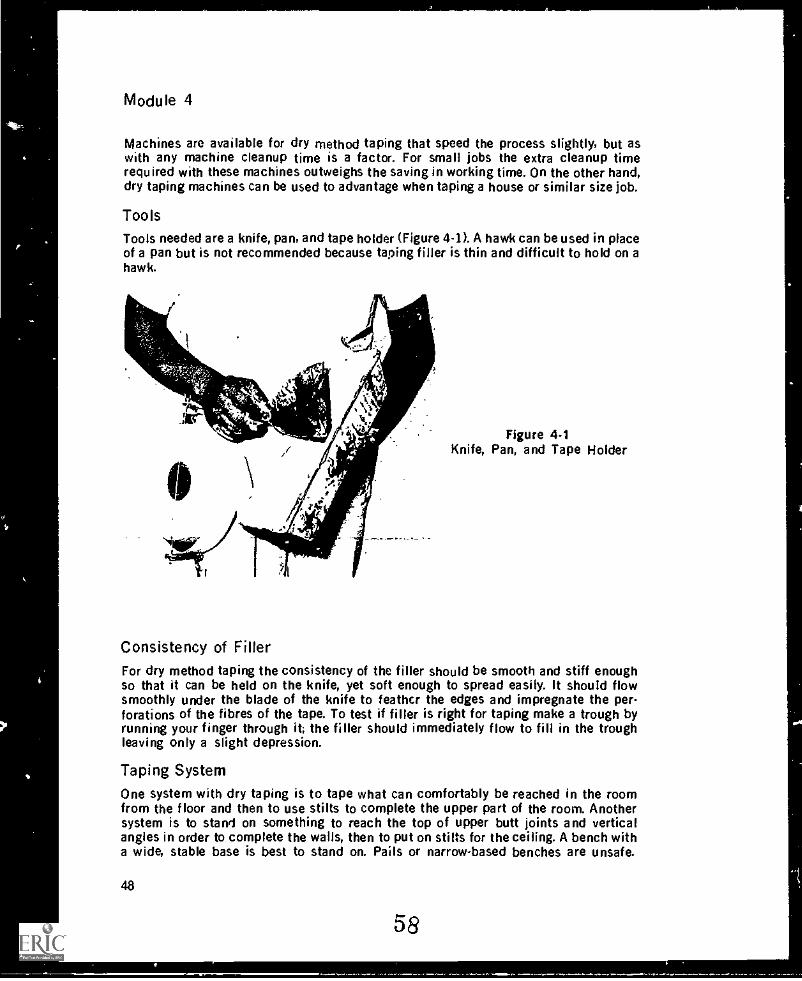
Module 4
Machines are available for dry method taping that speed the process slightly, but aswith any machine cleanup time is a factor. For small jobs the extra cleanup timerequired with these machines outweighs the saving in working time. On the other hand,dry taping machines can be used to advantage when taping a house or similar size job.
ToolsTools needed are a knife, pan, and tape holder (Figure 4-1). A hawk can be used in placeof a pan but is not recommended because taping filler is thin and difficult to hold on ahawk.
8Figure 4-1
Knife, Pan, and Tape Holder
Consistency of FilterFor dry method taping the consistency of the filler should be smooth and stiff enoughso that it can be held on the knife, yet soft enough to spread easily. It should flowsmoothly under the blade of the knife to feather the edges and impregnate the per-forations of the fibres of the tape. To test if filler is right for taping make a trough byrunning your finger through it; the filler should immediately flow to fill in the troughleaving only a slight depression.
Taping System
One system with dry taping is to tape what can comfortably be reached in the roomfrom the floor and then to use stilts to complete the upper part of the room. Anothersystem is to stand on something to reach the top of upper butt joints and verticalangles in order to complete the walls, then to put on stilts for the ceiling. A bench witha wide, stable base is best to stand on. Pails or narrow-based benches are unsafe.
48
58
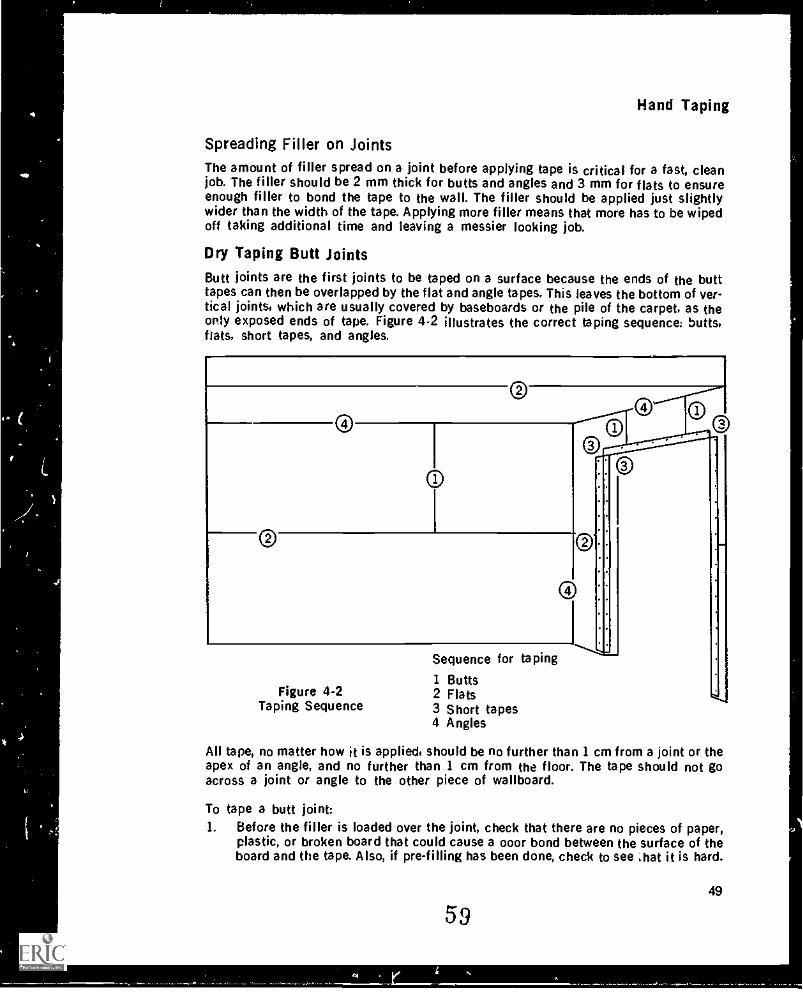
Hand Taping
Spreading Filler on JointsThe amount of filler spread on a joint before applying tape is critical for a fast, cleanjob. The filler should be 2 mm thick for butts and angles and 3 mm for flats to ensureenough filler to bond the tape to the wall. The filler should be applied just slightlywider than the width of the tape. Applying more filler means that more has to be wipedoff taking additional time and leaving a messier looking job.
Dry Taping Butt JointsButt joints are the first joints to be taped on a surface because the ends of the butttapes can then be overlapped by the flat and angle tapes. This leaves the bottom of ver-tical joints, which are usually covered by baseboards or the pile of the carpet, as theonly exposed ends of tape. Figure 4-2 illustrates the correct taping sequence: butts,flats, short tapes, and angles.
©
ooS___.
o
Figure 4-2Taping Sequence
Sequence for taping
1 Butts2 Flats3 Short tapes4 Angles
*----...
All tape, no matter how it is applied, should be no further than 1 cm from a joint or theapex of an angle, and no further than 1 cm from the floor. The tape should not goacross a joint or angle to the other piece of wallboard.
To tape a butt joint:1. Before the filler is loaded over the joint, check that there are no pieces of paper,
plastic, or broken board that could cause a 000r bond between the surface of theboard and the tape. Also, if pre-filling has been done, check to see ,hat it is hard.
49
59
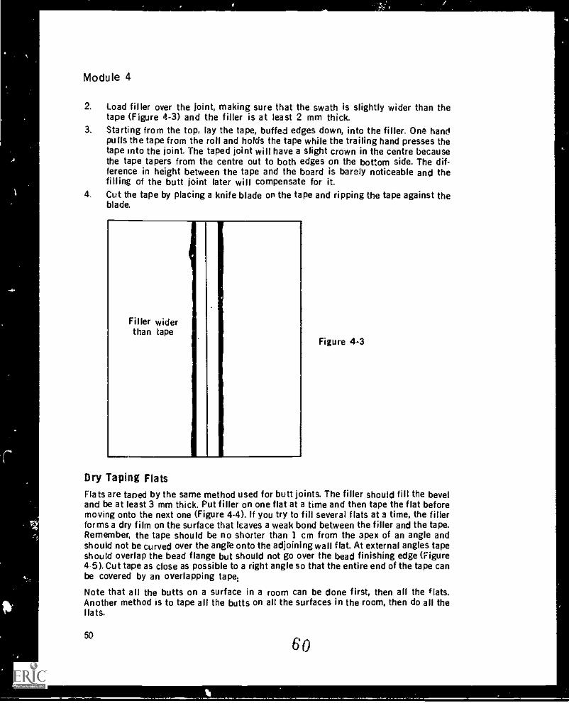
Module 4
2. Load filler over the joint, making sure that the swath is slightly wider than thetape (Figure 4-3) and the filler is at least 2 mm thick.
3. Starting from the top, lay the tape, buffed edges down, into the filler. One handpulls the tape from the roll and holds the tape while the trailing hand presses thetape into the joint. The taped joint will have a slight crown in the centre becausethe tape tapers from the centre out to both edges on the bottom side. The dif-ference in height between the tape and the board is barely noticeable and thefilling of the butt joint later will compensate for it.
4. Cut the tape by placing a knife blade on the tape and ripping the tape against theblade.
Filler widerthan tape
Figure 4-3
Dry Taping FlatsFlats are tared by the same method used for butt joints. The filler should fill the beveland be at least 3 mm thick. Put filler on one flat at a time and then tape the flat beforemoving onto the next one (Figure 4-4). If you try to fill several flats at a time, the fillerforms a dry film on the surface that leaves a weak bond between the filler and the tape.Remember, the tape should be no shorter than 1 cm from the apex of an angle andshould not be curved over the angle onto the adjoining wall flat. At external angles tapeshould overlap the bead flange but should not go over the bead finishing edge (Figure4-5). Cut tape as close as possible to a right angle so that the entire end of the tape canbe covered by an overlapping tape:
Note that all the butts on a surface in a room can be done first, then all the flats.Another method is to tape all the butts on all the surfaces in the room, then do all theflats.
50
60
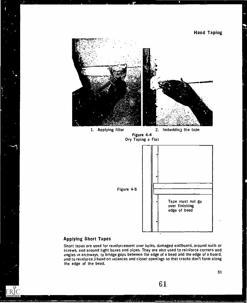
Hand Taping
1. Applying fillerFigure 4-4
Dry Taping a Flat
Figure 4-5
Tape must not goover finishingedge of bead
.1...1Applying Short TapesShort tapes are used for reinforcement over holes, damaged wallboard, around nails orscrews, and around light boxes and pipes. They are also used to reinforce corners andangles in archways, to bridge gaps between the edge of a bead and the edge of a board,and to reinforce Jbead on valances and closet openings so that cracks don't form alongthe edge of the bead.
51
61
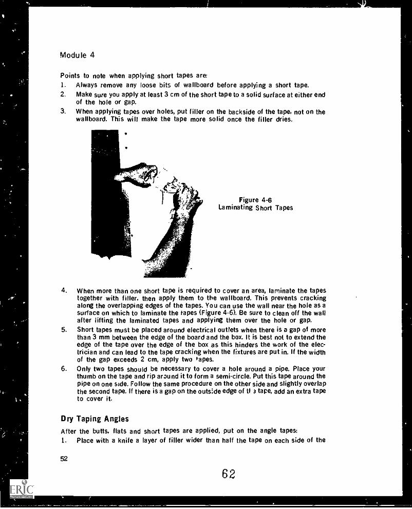
Module 4
Points to note when applying short tapes are:1. Always remove any loose bits of wallboard before applying a short tape.2. Make sure you apply at least 3 cm of the short tape to a solid surface at either end
of the hole or gap.3. When applying tapes over holes, put filler on the backside of the tape, not on the
wallboard. This will make the tape more solid once the filler dries.
Figure 4.6Laminating Short Tapes
4. When more than one short tape is required to cover an area, laminate the tapestogether with filler, then apply them to the wallboard. This prevents crackingalong the overlapping edges of the tapes. You can use the wall near the hole as asurface on which to laminate the tapes (Figure 4-6). Be sure to clean off the wallafter lifting the laminated tapes and applying them over the hole or gap.
5. Short tapes must be placed around electrical outlets when there is a gap of morethan 3 mm between the edge of the board and the box. It is best not to extend theedge of the tape over the edge of the box as this hinders the work of the elec-trician and can lead to the tape cracking when the fixtures are put in. If the widthof the gap exceeds 2 cm, apply two tapes.
6. Only two tapes should be necessary to cover a hole around a pipe. Place yourthumb on the tape and rip around it to form a semi-circle. Put this tape around thepipe on one side. Follow the same procedure on the other side and slightly overlapthe second tape. If there is a gap on the outside edge of ti 3 tape, add an extra tapeto cover it.
Dry Taping AnglesAfter the butts. flats and short tapes are applied, put on the angle tapes:1. Place with a knife a layer of filler wider than half the tape on each side of the
52
62
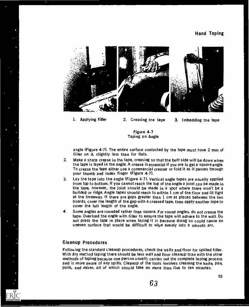
Hand Taping
1. Applying filler 2. Creasing the tape 3. Imbedding the tape
Figure 4-7Taping an Angle
angle (Figure 4-7). The entire surface contacted by the tape must have 2 mm offiller on it, slightly less than for flats.
2. Make a sharp crease in the tape, creasing so that the buff side will be down whenthe tape is Payed in the angle. A crease is essential if you are to get a square angle.To crease the tape either use a commercial creaser or fold it as it passes throughyour thumb and index finger (Figure 4-7).
3. Lay the tape into the angle (Figure 4-7). Vertical angle tapes are usually appliedfrom top to bottom. If you cannot reach the top of the angle a joint can be made inthe tape; however, the joint should be made in a spot where there won't be abuildup or ridge. Angle tapes should reach to within 1 cm of the floor and fit tightat the threeway. If there are gaps greater than 1 cm at places between the twoboards, cover the length of the gap with a creased tape, then apply another tape tocover the full length of the angle.
4. Some angles are rounded rather than square. For round angles, do not crease thetape. Overload the angle with filler to ensure the tape will adhere to the wall. Donot press the tape in place when laying it in because doing so could cause anuneven surface that would be difficult to wipe evenly into a smooth arc.
Cleanup Procedures
Following the standard cleanup procedures, check the walls and floor for spilled filler.With dry method taping there should be less wall and floor cleanup than with the othermethods of taping because one person usually carries out the complete taping processand is more aware of any spills. Cleanup of the tools involves cleaning the knife, pan,pails, and mixer, all of which should take no more than five to ten minutes.
6353
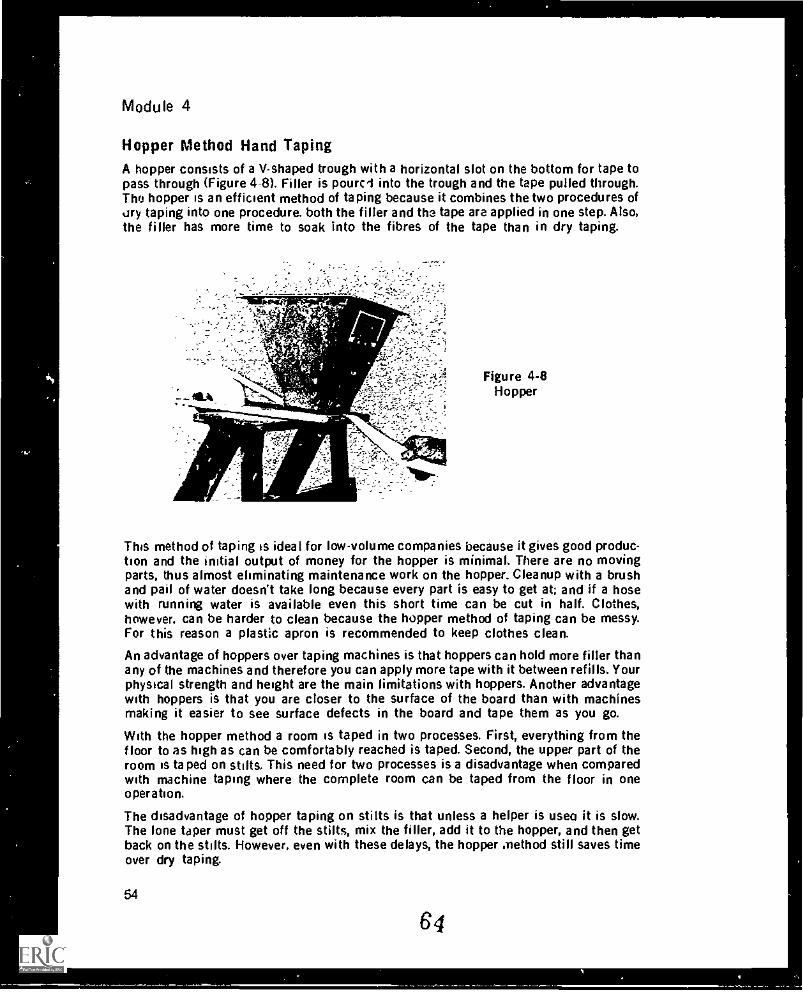
Module 4
Hopper Method Hand TapingA hopper consists of a V-shaped trough with a horizontal slot on the bottom for tape topass through (Figure 4-8). Filler is pourci into the trough and the tape pulled through.The hopper is an efficient method of taping because it combines the two procedures ofary taping into one procedure. both the filler and the tape are applied in one step. Also,the filler has more time to soak into the fibres of the tape than in dry taping.
Figure 4-8Hopper
This method of taping is ideal for low-volume companies because it gives good produc-tion and the initial output of money for the hopper is minimal. There are no movingparts, thus almost eliminating maintenance work on the hopper. Cleanup with a brushand pail of water doesn't take long because every part is easy to get at; and if a hosewith running water is available even this short time can be cut in half. Clothes,however, can be harder to clean because the hopper method of taping can be messy.For this reason a plastic apron is recommended to keep clothes clean.
An advantage of hoppers over taping machines is that hoppers can hold more filler thanany of the machines and therefore you can apply more tape with it between refills. Yourphysical strength and height are the main limitations with hoppers. Another advantagewith hoppers is that you are closer to the surface of the board than with machinesmaking it easier to see surface defects in the board and tape them as you go.
With the hopper method a room is taped in two processes. First, everything from thefloor to as high as can be comfortably reached is taped. Second, the upper part of theroom is taped on stilts. This need for two processes is a disadvantage when comparedwith machine taping where the complete room can be taped from the floor in oneoperation.
The disadvantage of hopper taping on stilts is that unless a helper is use(' it is slow.The lone taper must get off the stilts, mix the filler, add it to the hopper, and then getback on the stilts. However, even with these delays, the hopper method still saves timeover dry taping.
54
64
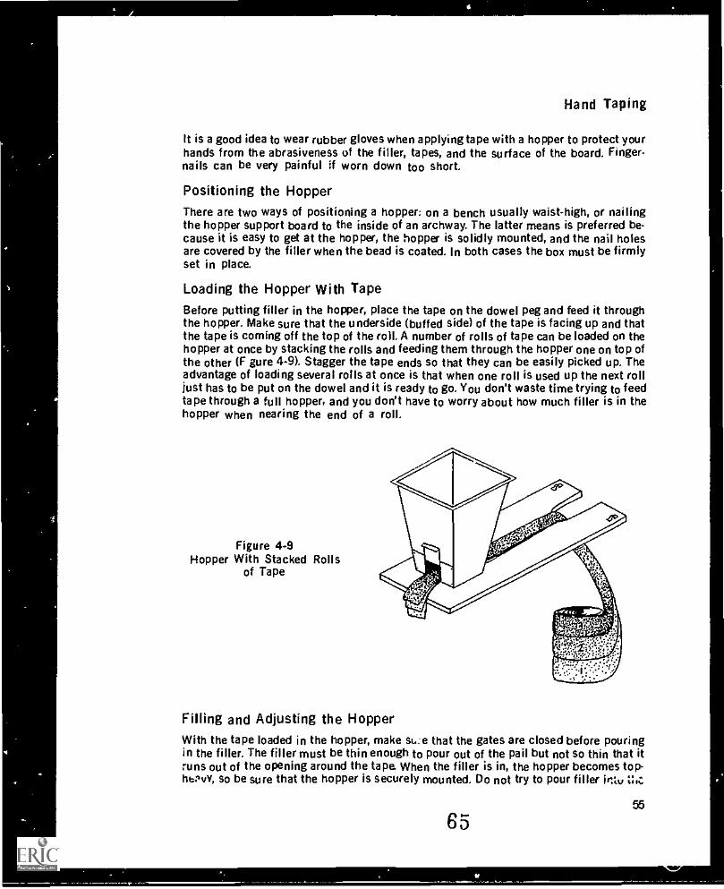
I
Hand Taping
It is a good idea to wear rubber gloves when applying tape with a hopper to protect yourhands from the abrasiveness of the filler, tapes, and the surface of the board. Finger-nails can be very painful if worn down too short.
Positioning the HopperThere are two ways of positioning a hopper; on a bench usually waist-high, or nailingthe hopper support board to the inside of an archway. The latter means is preferred be-cause it is easy to get at the hopper, the hopper is solidly mounted, and the nail holesare covered by the filler when the bead is coated. In both cases the box must be firmlyset in place.
Loading the Hopper With TapeBefore putting filler in the hopper, place the tape on the dowel peg and feed it throughthe hopper. Make sure that the underside (buffed side) of the tape is facing up and thatthe tape is coming off the top of the roil. A number of roils of tape can be loaded on thehopper at once by stacking the rolls and feeding them through the hopper one on top ofthe other (F gure 4-9). Stagger the tape ends so that they can be easily picked up. Theadvantage of loading several roils at once is that when one roll is used up the next rolljust has to be put on the dowel and it is ready to go. You don't waste time trying to feedtape through a full hopper, and you don't have to worry about how much filler is in thehopper when nearing the end of a roil.
Figure 4-9Hopper With Stacked Rolls
of Tape
Filling and Adjusting the HopperWith the tape loaded in the hopper, make that the gates are closed before pouringin the filler. The filler must be thin enough to pour out of the pail but not so thin that itruns out of the opening around the tape. When the filler is in, the hopper becomes top-hbPvv, so be sure that the hopper is securely mounted. Do not try to pour filler intt, Z;o:
6555
sr
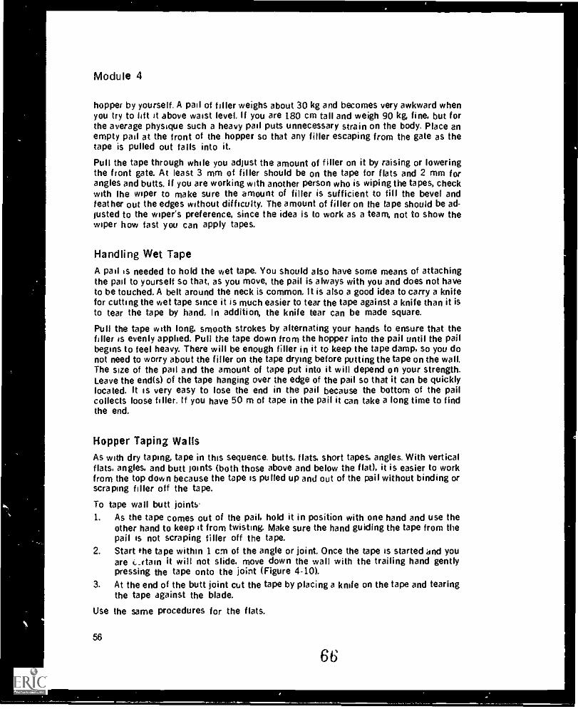
Module 4
hopper by yourself. A pail of filler weighs about 30 kg and becomes very awkward whenyou try to lift it above waist level. If you are 180 cm tall and weigh 90 kg, fine, but forthe average physique such a heavy pail puts unnecessary strain on the body. Place anempty pail at the front of the hopper so that any filler escaping from the gate as thetape is pulled out falls into it.
Pull the tape through while you adjust the amount of filler on it by raising or loweringthe front gate. At least 3 mm of filler should be on the tape for flats and 2 mm forangles and butts. If you are working with another person who is wiping the tapes, checkwith the wiper to make sure the amount of filler is sufficient to fill the bevel andfeather out the edges without difficulty. The amount of filler on the tape should be ad-justed to the wiper's preference, since the idea is to work as a team, not to show thewiper how fast you can apply tapes.
Handling Wet Tape
A pail is needed to hold the wet tape. You should also have some means of attachingthe pail to yourself so that, as you move, the pail is always with you and does not haveto be touched. A belt around the neck is common. it is also a good idea to carry a knifefor cutting the wet tape since it is much easier to tear the tape against a knife than it isto tear the tape by hand. In addition, the knife tear can be made square.
Pull the tape with long, smooth strokes by alternating your hands to ensure that thefiller is evenly applied. Pull the tape down from the hopper into the pail until the pailbegins to feel heavy. There will be enough filler in it to keep the tape damp, so you donot need to worry about the filler on the tape drying before putting the tape on the wall.The size of the pail and the amount of tape put into it will depend on your strength.Leave the end(s) of the tape hanging over the edge of the pail so that it can be quicklylocated. It is very easy to lose the end in the pail because the bottom of the pailcollects loose filler. If you have 50 m of tape in the pail it can take a long time to findthe end.
Hopper Taping WallsAs with dry taping, tape in this sequence. butts, flats, short tapes, angles. With verticalflats, angles, and butt joints (both those above and below the flat), it is easier to workfrom the top down because the tape is pulled up and out of the pail without binding orscraping filler off the tape.
To tape wall butt joints'1. As the tape comes out of the pail, hold it in position with one hand and use the
other hand to keep it from twisting. Make sure the hand guiding the tape from thepail is not scraping filler off the tape.
2. Start the tape within 1 cm of the angle or joint. Once the tape is started and youare ittain it will not slide, move down the wall with the trailing hand gentlypressing the tape onto the joint (Figure 4-10).
3. At the end of the butt joint cut the tape by placing a knife on the tape and tearingthe tape against the blade.
Use the same procedures for the flats.
56
66
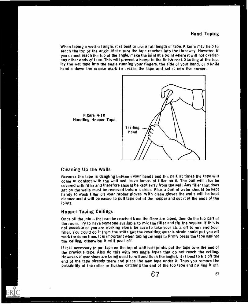
Hand Taping
When taping a vertical angle, it is best to use a full length of tape. A knife may help toreach the top of the angle. Make sure the tape reaches into the threeway. However, ifyou cannot reach the top of the angle, make the joint at a point where it will not overlapany other ends of tape. This will prevent a hump in the finish coat. Starting at the top,lay the wet tape into the angle running your fingers, the side of your hand, or a knifehandle down the crease mark to crease the tape and set it into the corner.
Figure 4.10Handling Hopper Tape
Trailinghand
Cleaning Up the WailsBecause the tape is dangling between your hands and the pail, at times the tape willcome in contact with the wall and leave lumps of filler on it. The pail will also becovered with filler and therefore should be kept away from the wall. Any filler that doesget on the walls must be removed before it dries. Also, a pail of water should be kepthandy to wash filler off your rubber gloves. With clean gloves the walls will be keptcleaner and it will be easier to pull tape out of the hopper and cut it at the ends of thejoints.
Hopper Taping CeilingsOnce all the joints that can be reached from the floor are taped, then do the top part ofthe room. Try to have someone available to mix the filler and fill the hopper. If this isnot possible or you are working alone, be sure to take your stilts off to mix and pourfiller. You could do it from the stilts but the resulting muscle strain could put you offwork for some time. It is important when taping ceilings to firmly press the tape againstthe ceiling, otherwise it will peel off.
If it is necessary to put tape on the top of wall butt joints, put the tape over the end ofthe previous tape. Also do this with any angle tapes that do not reach the ceiling.However, if machines are being used to roll and flush the angles, it is best to lift off theend of the tape already there and place the new tape under it. Thus you remove thepossibility of the roller or flusher catching the end of the top tape and pulling it off.
67 57
,
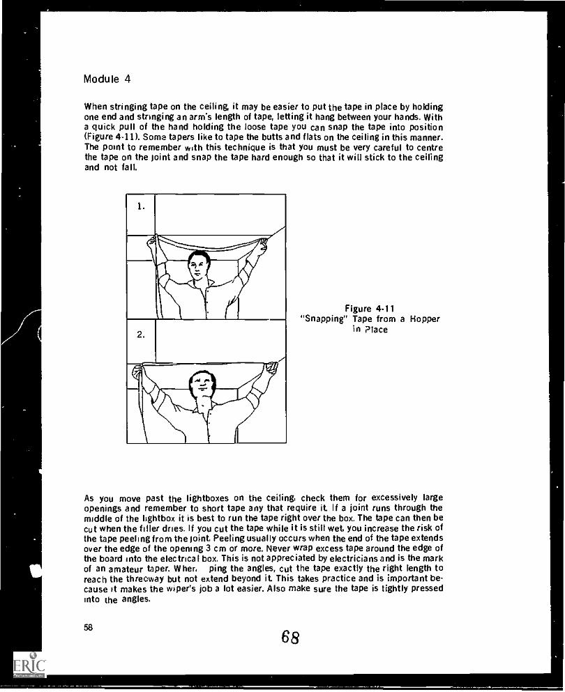
Module 4
When stringing tape on the ceiling, it may be easier to put the tape in place by holdingone end and stringing an arm's length of tape, letting it hang between your hands. Witha quick pull of the hand holding the loose tape you can snap the tape into position(Figure 4-11). Some tapers like to tape the butts and flats on the ceiling in this manner.The point to remember with this technique is that you must be very careful to centrethe tape on the joint and snap the tape hard enough so that it will stick to the ceilingand not fall.
1.
0$ ;it1al
2.
-t
Figure 4-11"Snapping" Tape from a Hopper
in Place
As you move past the lightboxes on the ceiling, check them for excessively largeopenings and remember to short tape any that require it. If a joint runs through themiddle of the lightbox it is best to run the tape right over the box. The tape can then becut when the filler dries. If you cut the tape while it is still wet, you increase the risk ofthe tape peeling from the joint, Peeling usually occurs when the end of the tape extendsover the edge of the opening 3 cm or more. Never wrap excess tape around the edge ofthe board into the electrical box, This is not appreciated by electricians and is the markof an amateur taper. Where ping the angles, cut the tape exactly the right length toreach the threoway but not extend beyond it. This takes practice and is important be-cause it makes the wiper's job a lot easier. Also make sure the tape is tightly pressedinto the angles.
58
68
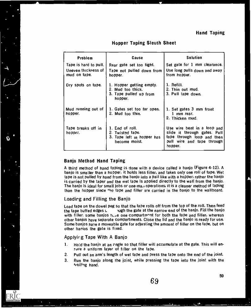
Hand Taping
Hopper Taping Sleuth Sheet
Problem Cause Solution
Tape is hard to pull. Rear gate set too tight. Set gate for 1 mm clearance.Uneven thickness of Tape not pulled down from Use long pulls down and awaymud on tape. hopper. from hopper.
Dry spots on tape. 1. Hopper getting empty. 1. Refill.2. Mud too thick. 2. Thin out mud.3. Tape pulled up from
hopper.3. Pull tape down.
Mud running out of 1. Gates set too far open. 1. Set gates 3 mm fronthopper. 2. Mud too thin. 1 mm rear.
2. Thicken mud.
Tape breaks off in 1. End of roll. Use wire bent in a loop andhoppn. 2. Twisted tape. slide it through gates. Pull
3. Tape left in hopper has tape through loop and thenbecome moist. pull wire and tape through
hopper.
Banjo Method Hand TapingA third method of hand taping is done with a device called a banjo (Figure 4-12). Abanjo is smaller than a hopper, it holds less filler, and takes only one roll of tape. Wettape is not pulled by hand from the banjo into a pail like with a hopper; rather the banjois carried by the taper and the wet tape Is applied directly to the wall from the banjo.The banjo is ideal for small jobs or one-mad operations; it is a cleaner method of tapingthan the hopper since Pre tape and filler are carried in the banjo to the wallboard.
Loadirg and Filling the BanjoLoad tape on the dowel peg so that the tape rolls off from the top of the roll. Then feedthe tape buffed edges t. Nigh the gate at the narrow end of the banjo. Fill the banjowith filler: some banjos h.. a one compartm^ot for both the tape and filler, whereasother banjos have separate compartments. Close the lid and the banjo is ready for use.Some banjos have a moveable gate for adjusting the amount of filler on the tape, but onother barrios the gate is fixed.
Applyir g Tape With A Banjo
1. Hord the banjo at an zngle so that filler will accumulate at the gate. This will en-?Aire a uniform layer of filler on the tape.
2. Pull out an arm's length of wet tape and press the tape onto the end of the joint.3. Run the banjo along the joint, while pressing the tape into the joint with the
tra i ling hand.
6959

4Module 4
4. For taping vertical joints use the handle on top of the banjo for horizontal jointsuse the handle mounted on the side.
5. Some banjos have a toothedge for tearing the tape but with others you will have totear the tape against a knife.
6. Tape in the same sequence as with the hopper, dividing the room into a lower sec-tion and upper section.
Figure 4-12Banjo
EXERCISE
.3
Hand Taping1. What is to function of a drywall tape?2. List five properties of paper tape.3. Where can gauze tape be used?4. In what sequence should angles, butts, flats, and short tapes be applied?5. Why should you not press tapes into angles that are to be rounded?6. State where the ends of tape should be in relation to:
a. Ends of jointsb. Beads
c. Bottoms of anglesd. Threewayse. electrical outlets in joints
7. When would hand dry taping likely be used?8. What is a quick way of telling if the consistency of the filler is right for taping?9. How thick should filler for taping be spread on butts? Flats? Angles?
10. Which is the correct system flr dry taping flats?a. Load filler in two or three flats, then lay the tape in.b. Load filler in one flat. then immediately lay the tape into the flat.
60
70
Hand Taping
11. Name three uses for short tapes.12. How many short tapes are required to tape around a pipe?13. Short tapes must be placed around electrical outlets when there is a gap of more
than between the edge of the board and the box.14. What must be done when dry taping angles to ensure a square angle?15. True or False? When dry taping butt joints, the width of filler laid on the joint
should be about twice the width of the tape?16. What is the main advantage of the hopper method of tapir.g over the dry taping
method?
17. What is an advantage of a hopper over a tapping machine? A disadvantage?18. True or False? An efficient way of hopper taping is to stack rolls of tape.19. What is the purpose of the gate on a hopper?20. When hopper taping, how do you crease tapes for angles?21. How do you join two tapes on a vertical angle that will be rolled and flushed?22. What causes tapes to peel off a ceiling before they are wiped?23. What is the major difference between taping with a hopper and taping with a
banjo?
71 61
(
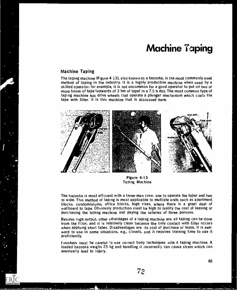
Machine Taping
Machine TapingThe taping machine (Figure 4-13), also known as a bazooka, is the most commonly usedmethod of taping in the industry. It is a highly productive machine when used by askilled operator; for example, it is not uncommon for a good operator to put on two ormore boxes of tape (upwards of 3 km of tape) in a 7.5 h day. The most common type oftaping machine has drive wheels that operate a plunger mechanism which coats thetape with filler. It is this machine that is discussed here.
Figure 4-13Taping Machine
The bazooka is most efficient with a three-man crew: one to operate the taper and twoto wipe. This method of taping is most applicable to multiple units such as apartmentblocks, condominiums, office blocks, high rises, where there is a great deal ofwallboard to tape. Obviously production must be high to justify the cost of leasing orpurchasing the taping machine and paying the salaries of three persons.
Besides high output. other advantages of a taping machine are: all taping can be donefrom the flpor, and it is relatively clean because the cnly contact with filler occurswhen applying short tapes. Disadvantages are. its cost of purchase or lease, it is awk-ward to use in some situations, e.g., closets, and it requires training time to use itproficiently.
Finishers must be careful to use correct body techniques Nith a taping machine. Aloaded bazooka weighs 25 kg and handling it incorrectly can cause strain which caneventually lead to injury.
72
63
-
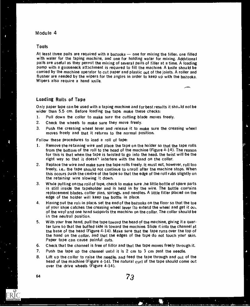
Module 4
Tools
At least three pails are required with a bazooka one for mixing the filler, one filledwith water for the taping machine, and one for holding water for mixing. Additionalpails are useful as they permit the mixing of several pails of filler at a time. A loadingpump with a gooseneck attachment is required to fill the machine. A knife should becarried by the machine operator to cut paper and plastic out of the joints. A roller andflusher are needed by the wipers for the angles in order to keep up with the bazooka.Wipers also require a hand knife.
Loading Rolls of TapeOnly paper tape can be used with a taping machine and for best results it should not bewider than 5.5 cm. Before loading the tape, make these checks:1. Pull down the collar to make sure the cutting blade moves freely.2. Check the wheels to make sure they move freely.3. Push the creasing wheel lever and release it to make sure the creasing wheel
moves freely and that it returns to the normal position.
Follow these procedures to load a roll of tape:1. Remove the retaining wire and place the tape on the holder so that the tape rolls
from the bottom of the roll to the head of the machine (Figure 4-14). The reasonfor this is that when the tape is twisted to go into the head, the twist will be theright way so that it doesn't interfere with the hand on the collar.
2. Replace the wire and make sure the tape rolls freely. It must not, however, roll toofreely, i.e., the tape should not continue to unroll after the machine stops. Whenthis occurs push the centre of the tape so that the edge of the roll rubs slightly onthe retaining wire slowing it down.
3. While putting on the roil of tape, check to make sure .he little bottle of spare partsis still inside the tapeholder and is held in by the wire. The bottle containsreplacement blades, cotter pins, springs, and needles. A little filler placed on theedge of the holder will keep the bottle in place.
4. Having out the rot, in place, set the end of the bazooka on the floor so that the toeof your shoe catches the creasing wheel lever (to extend the wheel and get it ou..of the way) and one hand supports the machine on the collar. The collar should bein the neutral position.
5. With your free hand, pull the tape toward the head of the machine, giving it a quar-ter turn so that the buffed side is toward the machine. Slide rt into the channel atthe base of the head (Figure 4-14). Make sure that the tape runs over the top ofthe hand on the collar, and that the edges of the tape do not touch your skin.Paper tape can cause painful cuts.
6. Check that the channel is free of filler and that the tape moves freely through it.7. Push the tape up the channel until it is 2 cm to 3 cm past the needle.8. Lift up the collar to raise the needle, and feed the tape through and out of the
head of the machine (Figure 4-14). The natural curl of the tape should come outover the drive wheels (Figure 4-14).
64 73
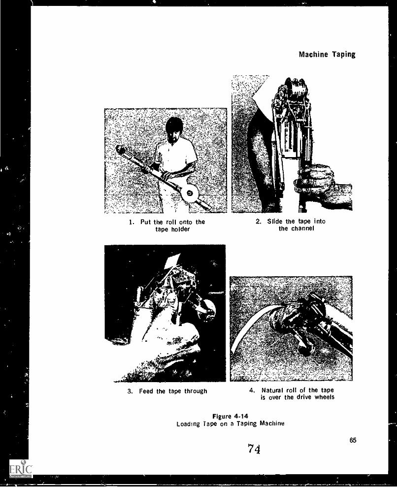
Machine Taping
1. Put the roll onto thetape holder
3. Feed the tape through
2. Slide the tape intothe channel
4.;i2g...111:1., 0) <;_-" ' ;)-,- ,
4. Natural roll of the tapeis over the drive wheels
Figure 4-14Loading Tape on a Taping Machine
7465
Module 4
9 When the tape appears over the drive wheels, pull down on the collar to cut thetape and check that the blade is making a clean cut. Rough, torn edges or jammingof the blade indicates that the blade is broken or dull and should be replaced.Several pieces of tape should be cut to make sure the blade is sharp and freelyreturns to the neutral position. Note that wet tape will not cut and will jam theblade, so pull enough tape through until the blade cuts dry tape.
Filling A Taping Machine
Consistency of FilerFiller should be mixed fairly thin and smooth so that it can be poured from one pail toanother. Filler for flats is usually thicker than filler for the angles. If the flier is toothin for the flats, the tape will slide along the joint and leave one end too short. Thinfiller on flats can also cause the upper edge of the tape to peel off the wall when it isapplied because the filler will not be thick enough to hold it in place. The filler is mixedthinner for angles so that the tape can be more easily creased to form a square corner.However, the filler can be too thin and the sign that this is the case is that filler will rundown the wall when the angle is flushed.
The Loading PumpPlace the round tube of the pump in a pail of filler. The side of the pail should slide be-tween the round tube and the foot plate. The pump can then be slightly turned and thepail wedged tightly in place by stepping on the foot pad. This ensures that the pumpwill not wobble when the taping machine is being filled.
Use the pump without a screen when filling the taping machine. The reason for this isthat if the screen plugs the pump has to be pulled out of the filler and the screen clezn-ed Thir is a mess/ and time-consuming procedure. The machine operator is usuallysupposed to keep two co-workers busy. Stopping for any :angth of time means that theywill be idle and thus the cost in wages of cleaning the screen is tripled. Mix the Wier sothat there are no lumps. However, even if a few lumps pass into the machine (sincethere is no screen), they shouldn't cause any problems.
To prevent air bubbles from getting into the bazooka, the pump should not be removedfrom the pail. If additional filler is required it should be poured into the pail. Air bub-bles are a major problem in that if seen they slow down the wiper's work, and if notseen they create defects in the finished work.
Pump the filler until it is visible at the end of the gooseneck. This also prevents airfrom being pumped into the bazooka. If the pump is new or was thoroughly washed outafter the last use, you may have trouble getting it to pump. Short, fast strokes on thehandle should get it going, if not, remove the pump from the filler pail and place it in apail of water, again giving the handle short. fast strokes. If it still does not work, turn itupside d...wn and pour water into it or pour water into the exit port and pump thehandle. This should get the plunger wet and Create the necessary su..tion to pump thefiller. However, if all this fails, a part is probably worn out and you should return thepump to the manufacturer or the distributor for service.
66 75
t
rs-
a
Machine Taping
Filling Procedures1. The small hook-shaped lever on the right side of the head of the bazooka operates
the flap that lets filler out onto the tape. During taping, the flap lever must be upand the flap open; during filling the lever must be down and the flap closed. Theflap lever strikes against a flat pulley when it is pushed down. This pulley must bepushed in before the lever can be set in its down position. The pully is conlectedto a shaft; this shaft engages and disengages a drive mechanism that turns thedrum, winds the cable, and pulls up the plunger when the bazooka is operated.During taping, the pulley must be pulled out; during filling it must be pushed in.Prior to filling the bazooka:a. Push the flap lever down until it strikes the pulley.b. As the lever strikes the pulley, push the pulley in with the thumb of your other
hand and continue pushing the lever until it reaches the down position. Notethat the lever must be completely down so that the flap is tightly closed andthus no filter will flow out the head of the machine Also note that the pulleymust be pushed in to disengage the drive mechanism allowing the drum,cable, and plunger, to roll freely as the bazooka tube fills.
2. Locate the filling nozzle on the flat plate on the bazooka head. This nozzle con-tains a spring loaded v ve that allows filler to flow in but not out.
3. Insert the nozzle into the opening at the end of the gooseneck of the pump.4. Lay the bazooka into the cradle of the gooseneck. It should stand by itself with the
wheels facing away from the pail.5. Place your left foot en the foot pad and your left hand at the open end of the
bazooka to feel the plunger when it reaches the top. Take care to keep your fingersin the middle of the tube, not resting on the side. The plunger can easily run overyour fingers because of the strong hydraulic pressure acting on it. This is verypainful and if it does happen and you are unable to reach the valve that releasesthe pressure, call for heip.
6. Pump filler into the bazooka. It should take nine to eleven pumps of the handle tofill it. Remember this because any more means there is likely a leak somewhereand air is getting into the bazooka.
7. As soon as you feel the plunger reaching the top, stop pumping; too muchpressure will force the plunger out the end.
8. Remove the machine from the cradle and hold the head so that it points into thepail.
9. Lift up the lever that operates the flap to the taping position. This will cause a bitof Mier to squirt out of the head from the pressure in the tube. Wipe the excessfiller from the tape on the edge of the pail.
10. The bazooka is now ready for use.
Problems When Filling A Taping MachineSometimes filler will run out of the valve as you pick up the machine. This means thatsomething has jammed the valve open. If it is left jammed while the tape is run onto the
the filler will run out the vaive and reduce the amount going onto the tape, as wellas make a mess. By poking inside the nozzle with a nail or a rigid piece of wire, you can
76 67
4.
t
,
Module 4
usually free the valve. Do not use plastic-coated electrical wire since a piece of thecoating could be cut off and itself get caught in the end of the valve. If after this at-tempt. the valve still remains stuck, you may have to remove it for cleaning.
You can remove the valve by first loosening the set screw that locks the valve in placein the head and then by tapping a screwdriver against the screw on the valve. If thisdoes not budge the valve you can use a pair of pliers but make sure to place the pliersat the bottom of the valve. Twist the valve with the pliers to pull it out. Se very carefulnot to bend or otherwise disfigure the valve. Wash the valve in water and remove thematerial jamming it. Check that the spring has enough tension to form a tight seal. Inreplacing the valve, make sure it sits squarely in the hole. You may have to tap it a bitto press it back into the hole but do not tap the end of the valve with a hard material.Instead use i. piece of wood or similar soft material to avoid damage that would preventthe nozzle from fitting tightly into the gooseneck.
Sometmes tiller will not pass through the valve into the bazooka even though the valveappears to be clean. This may be caused by dried filler trapped in the spring preventingthe valve from opening completely. To correct this problem, remove the valve and tapthe spring to dislodge the dry filler, then work the spring until the valve freely opensand closes. In the future, make sure to wash the valve thoroughly to prevent arecurrence of the problem.
Another problem that can arise when filling a bazooka is that on well used machinesthe cutter blade chain becomes slack and can jam the winding key. If pressure is thenapplied by the pump, it is possible to break the cable. Check for a slack chain and ifnecessary have it replaced.
Rinsing the Machine HeadWhenever the machine is stopped for five minutes or more, place the head in a pail ofwater to prevent filler from drying and jamming the moving parts. Even when themachine is in use, periodic dousing of the head in water is a good idea. Before im-mersing the head (Note: these steps aren't required for a quick rinse):1. Remove the tape from the head because it gets soft when wet and will tear when
the needle tries to pull it through. Wet, soggy tape will jam the cutting blade.2. Close the flap tha holds filler in the tube. (Also close this flap whenever setting
down the machine Head first.) The closed flap will prevent filler leaking out andthus the plunger from sliding down the tube without the cable winding up. If thisshould occur the slack cable could become tangled and break when the machineis filled again.
Taping Sequence for MachinesThe best sequence for machine taping a room is usually tts on the ceiling, butts onthe walls, flats on the ceiling, flats on the walls, short tapes, and angles. The reasonsfor doing all the butts in the room first, then all the flats rather than doing the buttsand flats on the ceiling, then the butts and flats on each wall are:1. The wipper will not have to wipe interesecting butt and flat tapes where both
tapes are unwiped.2. The taper and wiper will stay out of each other's way.
68
77
.
o'
Machine Taping
A recommended sequence for applying angle tapes with a machine is as follows:1. Start at the first vertical angle closest to the door as you walk in the room.2. Tape the vertical angle.3. Tape the horizontal angle to the right.4. And so on, the vertical angle, then the horizontal angle to the right until you return
to the vertical angle you started at. Note that taping to the right is recommendedbecause most taping machines are designed to work best to the right.
Procedures With A Newly Filled Bazooka1. Each time a bazooka is newly filled:
a. Give the winding key on the left side of the head a turn or two to bring theplunger up tight against the filler in the tube and feed filler onto the tape. Thiswill decrease the chance of dry spots at the beginning of a tape.
b. Run a horizontal wall flat (it need be no more than 1 m) that does not interferewith butt joints; or on the off chance that there isn't such a flat in the roomrun an upper wall butt joint or a vertical flat. This procedure eliminates dryspots or air pockets under the tape by ensuring that the plunger cable isbrought up tight against the filler and does not slide back as it would in theupright position if you did a ceiling flat first.
Basic Procedures For Machine Taping Joints1. To begin taping, put both wheels of the machine on the wallboard at the beginning
of the joint or angle. To start with a section of tape is pre-run, then lifted from thewallboard and set in place. Pre-running is necessary so that you can start the tapeexactly where you want it.
2. Roll the wheels forward, simultaneously pushing the collar forward to advance thetape. Thus the tape and filler will feed together. Don't worry about marks left bythe wheels as they will be covered when the joint is coated.
3. For upper butts pre-run approximately 15 cm of tape then holding the tape firmwith the hand on the collar lift the 15 cm of tape off the joint. For flats andhorizontal angles pre-run approximately 8 cm. And for lower butts and verticalangles pre-run enough tape (starting at a comfortable height usually about 60 cmfrom the floor) so that when you lift the tape from the wall it will reach the bottomof the joint without you having to bend your back (Figure 4.15). The object here isto put the least strain possible on the back.
4. Set the pre-run tape in place using the creasing wheel as a guide at the start of thejoint (Figure 4-16). Some overhang is necessary to compensate for dragging of thetape when the joint is run. For butts and vertical angles leave an overhang of 3 cm;for flats and horizontal angles leave 6 cm. If you over compensate the wiper willcut the tape to the right length. You are now ready to run the joint.
5. Before starting to run flats and horizontal angles make sure the drive wheels areright against the angle. On lower butts and vertical angles the drive wheels shouldbe no closer than 3 cm to the floor.
6. With both wheels on the wallboard ,,art to run the machine, snapping the creasingwheel against the tape as soon as possible after starting off.
78
69
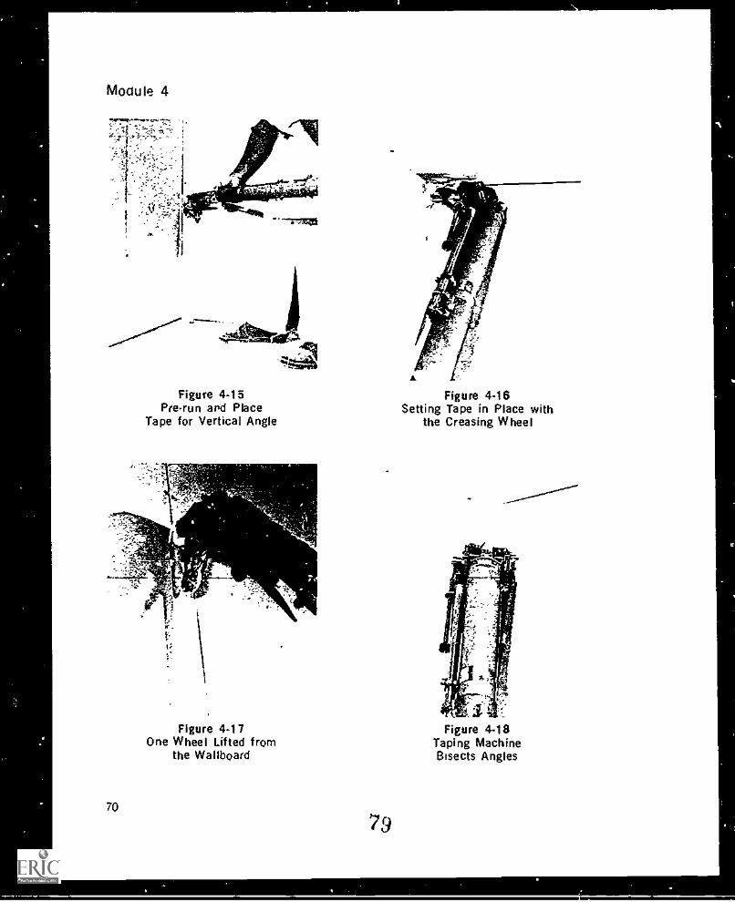
i
Module 4
Figure 4-15Prerun apci Place
Tape for Vertical Angle
70
Figure 4-17One Wheel Lifted from
the Wallboard
79
Figure 4 -16Setting Tape in Place with
the Creasing Wheel
- .-----------
k
Figure 4-18Taping MachineBisects Angles
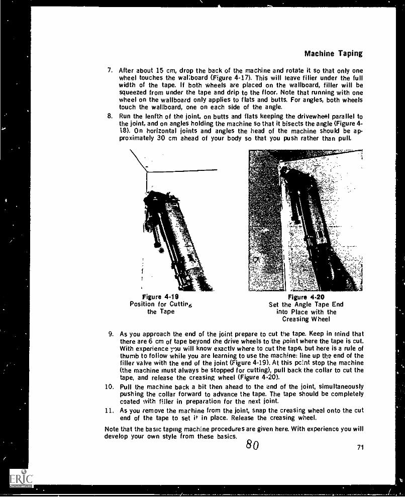
MachineMachine Taping
7. After about 15 cm, drop the back of the machine and rotate it so that only onewheel touches the wal;board (Figure 4-17). This will leave filler under the fullwidth of the tape. If both wheels are placed on the wallboard, filler will besqueezed from under the tape and drip to the floor. Note that running with onewheel on the wallboard only applies to flats and butts. For angles, both wheelstouch the wallboard, one on each side of the angle.
8. Run the lenfth of the joint, on butts and flats keeping the drivewheel parallel tothe joint, and on angles holding the machine so that it bisects the angle (Figure 4-I8). On horizontal joints and angles the head of the machine should be ap-proximately 30 cm ahead of your body so that you push rather than pull.
Figure 4.19Position for Cuttir,6
the Tape
1,70. *46:vas- vs6-#
Figure 420Set the Angle Tape End
into Place with theCreasing Wheel
9. As you approach the end of the joint prepare to cut the tape. Keep in mind thatthere are 6 cm of tape beyond the drive wheels to the point where the tape is cut.With experience ylti will know exactly where to cut the tape, but here is a rule ofthumb to follow while you are learning to use the machine: line up the end of thefiller valve with the end of the joint (Figure 4-19). At this pent stop the machine(the machine must always be stopped for cutting), pull back the collar to cut thetape, and release the creasing wheel (Figure 4.20).
10. Pull the machine back a bit then ahead to the and of the joint, simultaneouslypushing the collar forward to advance the tape. The tape should be completelycoated with filler in preparation for the next joint.
11. As you remove the machine from the joint, snap the creasing wheel onto the cutend of the tape to set it in place. Release the creasing wheel.
Note that the basic taping machine procedures are given here. With experience you willdevelop your own style from these basics.
80 71
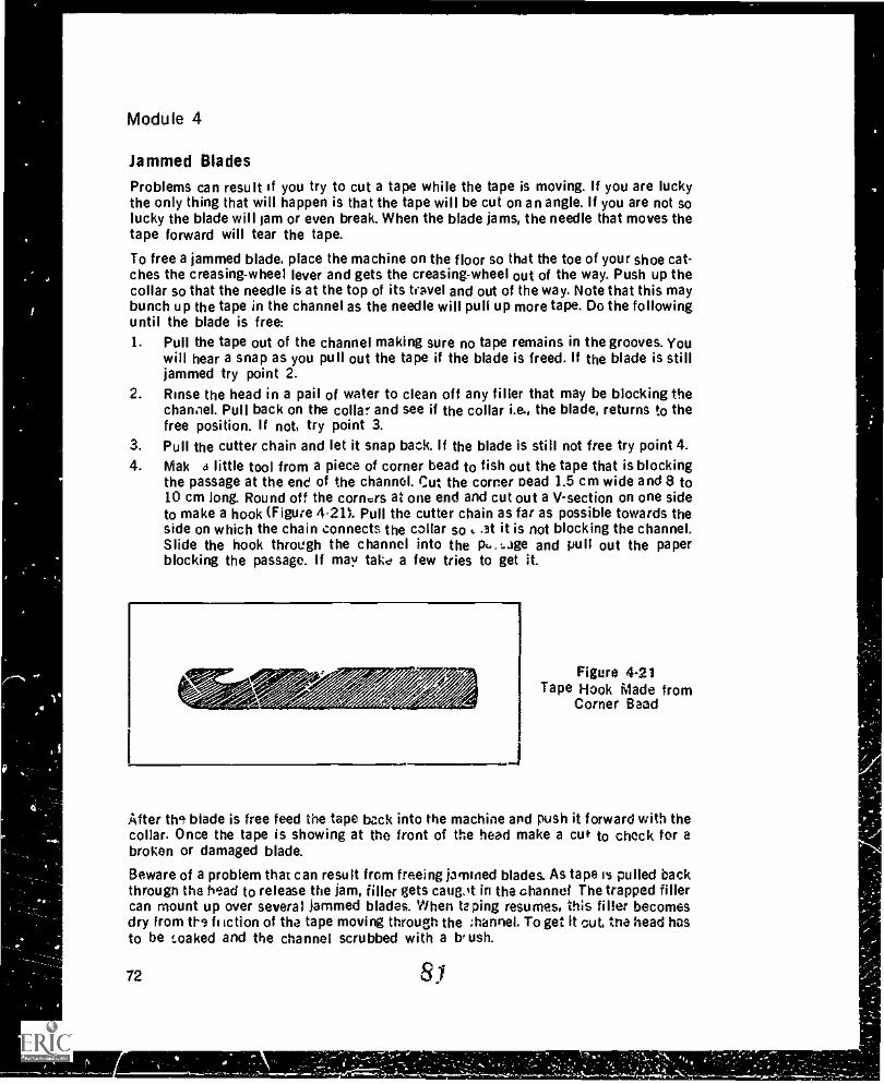
Module 4
Jammed Blades
Problems can result if you try to cut a tape while the tape is moving. If you are luckythe only thing that will happen is that the tape will be cut on an angle. If you are not solucky the blade will jam or even break. When the blade jams, the needle that moves thetape forward will tear the tape.
To free a jammed blade, place the machine on the floor so that the toe of your shoe cat-ches the creasing-wheel lever and gets the creasing-wheel out of the way. Push up thecollar so that the needle is at the top of its travel and out of the way. Note that this maybunch up the tape in the channel as the needle will pull up more tape. Do the followinguntil the blade is free:1. Pull the tape out of the channel making sure no tape remains in the grooves. You
will hear a snap as you pull out the tape if the blade is freed. If the blade is stilljammed try point 2.
2. Rinse the head in a pail of water to clean off any filler that may be blocking thechannel. Pull back on the collar and see if the collar i.e., the blade, returns to thefree position. if not, try point 3.
3. Pull the cutter chain and let it snap back. If the blade is still not free try point 4.4. Mak 4 little tool from a piece of corner bead to fish out the tape that is blocking
the passage at the end of the channel. Cut the corner Dead 1.5 cm wide and 8 to10 cm long. Round off the comas at one end and cut out a V-section on one sideto make a hook (Figure 4-21). Pull the cutter chain as far as possible towards theside on which the chain connects the collar so ..at it is not blocking the channel.Slide the hook through the channel into the p... gage and pull out the paperblocking the passage. If may take a few tries to get it.
Figure 4-21Tape Hook Made from
Corner Bead
After the blade is free feed the tape back into the machine and push it forward with thecollar. Once the tape is showing at the front of the head make a cu* to chock for abroken or damaged blade.
Beware of a problem that can result from freeing jammed blades. As tape is pulled backthrough the head to release the jam, filler gets caugot in the channel The trapped fillercan mount up over several jammed blades. When taping resumes, this filler becomesdry from ths f, fiction of the tape moving through the :hannel. To get it out, the head hasto be soaked and the channel scrubbed with a b, ush.
72 81
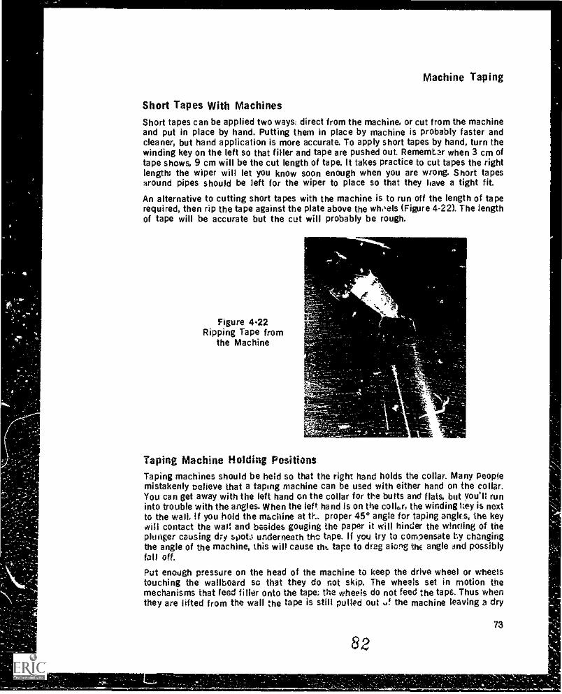
Machine Taping
Short Tapes With MachinesShort tapes can be applied two ways: direct from the machine, or cut from the machineand put in place by hand. Putting them in place by machine is probably faster andcleaner, but hand application is more accurate. To apply short tapes by hand, turn thewinding key on the left so that filler and tape are pushed out. Rememkar when 3 cm oftape shows, 9 cm will be the cut length of tape. It takes practice to cut tapes the rightlength; the wiper will let you know soon enough when you are wrong. Short tapesaround pipes should be left for the wiper to place so that they have a tight fit.
An alternative to cutting short tapes with the machine is to run off the length of taperequired, then rip the tape against the plate above the whitels (Figure 4-22). The lengthof tape will be accurate but the cut will probably be rough.
Figure 4.22Ripping Tape from
the Machine
lf
Taping Machine Holding PositionsTaping machines should be held so that the right hand holds the collar. Many peoplemistakenly believe that a taping machine can be used with either hand on the collar.You can get away with the left hand on the collar for the butts and flats, but you'll runinto trouble with the angles. When the left. hand Is on the collar, the winding key is nextto the wail. if you hold the machine at th, proper 45° angle for taping angles, the keywill contact the wal: and besides gouging the paper it will hinder the winoing of theplunger causing dry spots underneath the tape. if you try to compensate hy changingthe angle of the machine, this will cause tht tape to drag along thE angle dnd possiblyfall off.Put enough pressure on the head of the machine to keep the drive wheel or wheelstouching the wallboard so that they do not skip. The wheels set in motion themechanisms that feed filler onto the tape; the wheels do not feed the tap6. Thus whenthey are lifted from the wall the tape is still pulled out u! the machine leaving a dry
73
82
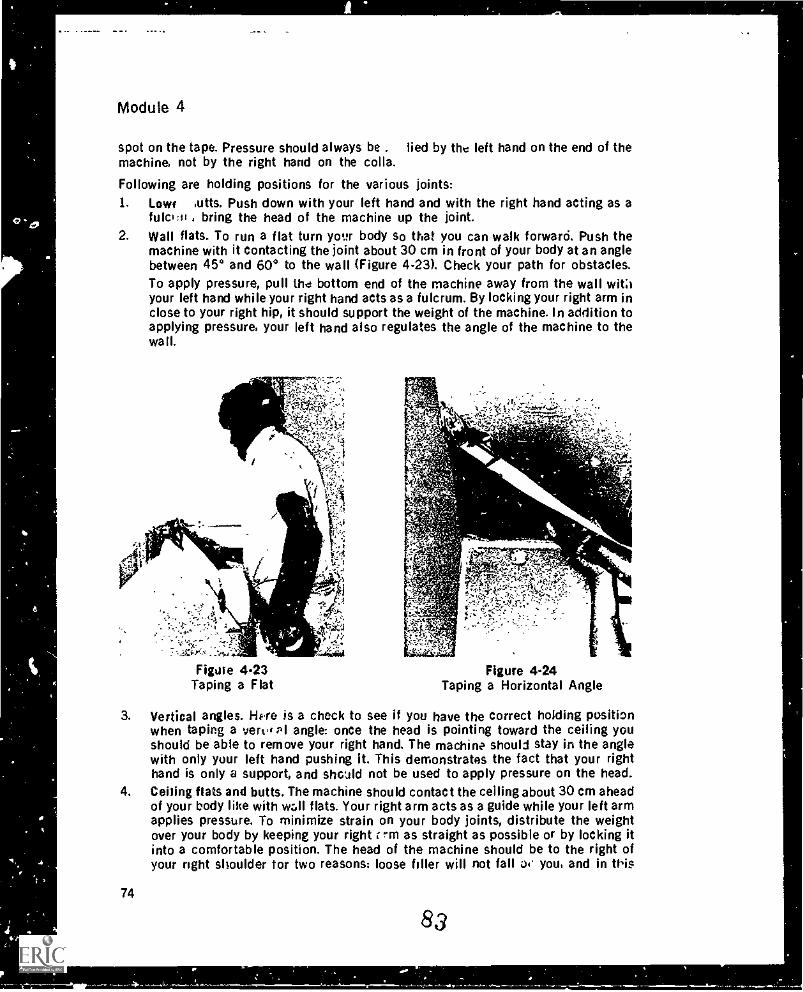
Module 4
spot on the tape. Pressure should always be . lied by the left hand on the end of themachine, not by the right hand on the colla.
Following are holding positions for the various joints:1. Lowe putts. Push down with your left hand and with the right hand acting as a
fulc:si , bring the head of the machine up the joint.2. Wall flats. To run a flat turn your body so that you can walk forward. Push the
machine with it contacting the joint about 30 cm in front of your body at an anglebetween 45° and 60° to the wall (Figure 4-23). Check your path for obstacles.To apply pressure, pull the bottom end of the machine away from the wall wit;1your left hand while your right hand acts as a fulcrum. By locking your right arm inclose to your right hip, it should support the weight of the machine. In addition toapplying pressure, your left hand also regulates the angle of the machine to thewall.
Figure 4.23Taping a Flat
Figure 424Taping a Horizontal Angle
3. Vertical angles. Hpre is a check to see if you have the correct holding positionwhen taping a vertu' PI angle: once the head is pointing toward the ceiling youshould be able to remove your right hand. The machine should stay in the anglewith only your left hand pushing it. This demonstrates the fact that your righthand is only a support, and shc:ild not be used to apply pressure on the head.
4. Ceiiing flats and butts. The machine should contact the ceiling about 30 cm aheadof your body like with w:411 flats. Your right arm acts as a guide while your left armapplies pressure. To minimize strain on your body joints, distribute the weightover your body by keeping your right r -m as straight as possible or by locking itinto a comfortable position. The head of the machine should be to the right ofyour right shoulder for two reasons: loose filler will not fall o4* you and in tiis
74
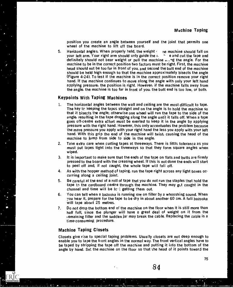
Machine Taping
position you create an angle between yourself and the joint that permits onewheel of the machine to lift off the board.
5. Horizontal angles. When properly held, the weight , ne machine should fall onyour left arm. Your right arm should only guide the t. " e and cut the tape anddefinitely should not bear weight or pull the machine ..-ng the angle. For themachine to be in the correct position two factors must be right. First, the machinehead should not be too far in front of you, and second the butt end of the machineshould be held high enough so that the machine approximately bisects the angle(Figure 4.24). To test if the machine is in the correct position remove your righthand. If the machine continues to move along the angle with only your left handapplying pressure, the position is right. However, if the machine falls away fromthe angle, the machine is too far in front of you, the butt end is too low, or both.
Keypoints With Taping Machines1. The horizontal angles between the wall and ceiling are the most difficult to tape.
The key to keeping the tapes straight and on the angle is to hold the machine sothat it bisects the angle; otherwise one wheel will run the tape to the side of theangle, resulting in the tape dragging along the angle until it falls off. When a tapegoes off-centre extra effort must be exerted to keep it in the angle by applyingpressure with the right hand. However, this only accentuates the problem becausethe more pressure you apply with your right hand the less you apply with your lefthand. With this grip the end of the machine will twist, causing the head of themachine to jump from side to side in the angle.
2. Take extra care when cutting tapes at threeways. There is litth:., tolerance as youmust put tapes tight into the threeways so that they form square angles whenwiped.
3. It is important to make sure that the ends of the tape on flats and butts are firmlypressed to the board with the creasing wheel. If this is not done the ends will startto peel off and, if not caught, the whole tape will fall off.
4. As with the hopper method of taping, run the tape right across any light boxes occurring along a ceiling joint.
5. Be careful at the end of a roll of tape that you do not run the staples that hold thetape to the cardboard centre through the machine. They may ge-t caught in thechannel and time will be lc' Z getting them out.
6. You can tell when a bazooka is running low on filler by a whooshing sound. Whenyou hear it, prepare for the tape to be dry in about another 60 cm. A full bazookawill tape about 25 metres.
7. Do not drop the bottom end of the machine on the floor when it is still more thanhalf full, since the plunger will have a great deal of weight on it from theI emaining filler and the sudden jar may break the cable. Replacing the cable is atime-consuming procedure.
Machine Taping ClosetsClosets give rise to special taping problems. Usually closets are not deep enough toenable you to tape the front angles in the normal way. The front vertical angles have tobe taped by stripping the tape off the machine and putting it into the bottom of theangle by hand. Set the machine on the floor so that the head of it points toward the
75
84
Module 4
ceiling Unwind about 3 cm of tape and filler from the machine and then pull the tapedown to the floor with your left hand. Use the index and second fingers of your righthand to form a brake as the tape slides through them. Also put pressure on and turn thewheels with your right hand so that filler is applied to the tape. Pull out enough tape sothat the machine can be pushed up the vertical angle.
The norizontal angle at the front of the closet also cannot be taped normally becauseyou cannot angle the machine enough to get one of the wheels on the wall. Only thewheel closest to the ceiling will touch. Leaving adequate overhang to account for theincreased drag, put the tape into the threeway and pull the machine along the angle.Snap the creasing wheel into the angle as far as it will go, but note that because of theangle at which the machine is being run, the tape will not have much of a crease. Thewheel just makes sure that the tape stays up. To move th machine, lean back and useyour arms to push and pull it above your body. You will not be able to cut the tape theright length, so aliow enough room at the end of the angle to run it out of the machineand make the cut. After cutting the tape use the creasing wheel to push the tape intothe angle so it doesn't fall off. Leave tc .he wiper the task of getting the tape centred inthe angle.
Machine Taping ValancesTaping the angle under a valance makes the job look more complete, and is an addedtouch that shows your concern for doing a good job. Most valances are too narrow toallow the machine to fit in the proper way because of the cutter-chain mechanism onthe right side. For this reason, the machine is usually run with your left hand on thecollar from right to left. This direction works with valances because the windowopening allows the winding key to turn freely. Be careful to avoid letting your righthand come in contact with the edge of the tape as it runs through the machine; the tapeis twisted at such an angle that it can easily cut your skin. Strip at least 60 cm of tapefrom the machine and place it in the angle so that the butt end of the machine can belifted as high as possible. Leave at least 15 cm of tape overhanging in the threeway tocompensate for drag. Lift your right hand high to get the wheels running as parallel aspossible to the angle and to minimize dragging of the tape. Snap the wheel into theangle e s soon as possible to get the tape to stick to the Pngle; all that is needed here isfor the crease of the tape to be close to the centre of the angle so that it can be put inplace by the wiper.
Tapi,.g closets and valances takes practice, so don't expect to be successful iss 'sttime. Also note that you can develop your own variations on the basics described hereto lo these angles.
Cleaning A Taping Machineif filler is left in the machine after taping is finished, push in the flat pulley on the rightside and crank the wheel on the left. This disengages the drive wheel mechanism in thehead while allowing the plunger cOlP to wind nn the drum as the filler is pushed out.During cleanup keep the gate valve lever in the up position to prevent any water fromentering the tube and causing the plunger to move and unwind the cable. Remove thetape from the rnachine to prevent it from getting wet. Wash the outside of the machinewith a brush making sure the entire machine is clean. The had must be especiallyclean, since any filler left to dry will prevent the machine from operating smoothly.Using a hose, force water through the filler valve until the escaping water is clean again
76
85
Machine Taping
making sure the gate valve lever is up so that the water is forced out over the wheels,not up into the tube. Force water up into the point just above the wheels where the tapecomes out; this cleans filler from the cable. Also force water through the holes :n thedrive wheel drum.
If a hose is not available, use the pump to clean the machine. After thoroughly cleaningthe pump, put the wl,ole pump into a clean pail of water so that water coming out of thegooseneck stays in the pail. Place the machine on the gooseneck with the wheels facingthe pump, and pump the water through the valve out over the wheels. Make sure thegate valve lever is in the up position so that water does not enter the machine.
After cleaning, give a light oiling to the drive wheels, chains, filler valve, and the chan-nel for the cutting blade. The machine should then be le' standing with the head to thefloor .o that any excess oil drains off. Do not oil a machuse if it is to be used soon after,since the oil could be transferred to the wall and prevent proper adhesion of the filler.No parts should be under tension when the machine is left star ling: the flap levershould be up and the collar in neutral.
A good cleaning job requires at least ten minutes. The cleaning should be done by theoperator. the only person who really cares about keeping the machine. in good operatingcondition.
Bazooka CourtesiesBecause it is very easy for tapers to get ahead of wipers, certain rules of etiquetteshould be followed to maintain harmony between the twc. Remember taping is teamwork: the better the team work the greater the production.
1. If a dry tape is left at the end of a joint, let the wiper know that the tape is dry andpeel the tape back to where the `viler stopped. Avoid leaving dry tapes longer than30 cm.
2. Concentrate on cutting the tapes the right length. If they are long or short, thewiper will have extra work and get behind.
3. If two tapes are put on the same joint, let the wiper 'Snow so that the method ofwiping can be adjusted accordingly. If two tapes occur along a vertical angleoverlap the higher tape and bring this to the wiper's attention.
4. If a joint occurs in an unusual place, bring it to the wiper's attention.5. If more than two tapes are used in one place, as in the case of electrical outlets or
in cavering a hole, have the wiper wipe them as you apply them.6. If plastic is found in an angle, have the wiper cut it out, since it is easier to cut out
the plastic when it is not covered with filler.7. Check with the wiper to make stire the filler is not too thick or too thin.8. Make sure the wheels do not skip and leave a dry spot under the tape on ceiling
joints because they are very difficult to reach from the floor.9. Place something under the end cf the pump gooseneck to catch any fiEier thai
runs out when loading the bazooka.10. Put the pail and pump where they will not hinder you or anyone else's movement,
i.e., away from the walls, the doorway, and not under ceiling joints.11. Keep the machine clean at all times.
n86
Module 4
Machine Taping Sleuth Sheet
Problem
Filler will not gointo automatictaper.
Cause
1. No filler at pump.
2. Pump not primed.
Solution
1. Fill pail with filler orscrape filler toward entryport on pump.
2. a. Put pump in water anduse short strokes onhandle until waterpumps through.
b. Pour water down exitport then pump handle.
3. Entry port of pump 3. Remove pump and cleanplugged. entry port; remove screen if
present but do not replace.Re-mix filler.
4. Dried filler at exit port of 4. Soak exit port to softenpump. filler and clean.
5. Spring in filler valve 5. Remove valve, soak inplugged. water, then clean spring
thoroughly.6. Flap lever on automatic 6. Push flap lever to fill
taper not in fill position. position.7. Plunger mechanism 7. Take machine apart and un-
jammed. jam. Check cutter chain furbinding with winder key.Check cable to make sure itwas properly wound.
8. Automatic taper is full.
Filler valve leaks. 1. Something stuck between 1. Use nail to tap on valve tovalve and seat. dislodge foreign material.
2. Remove filler valve andclean.
Filler does not flow 1. Flap lever not open. 1. Pull flap lever ail the wayonto tape. up.
2. Cable broken. 2. Push plunger from end ofmachine and replace cable.
3. Dirty head. 3. Soak head and removesolidified filler.
4. Drive wheels not turning. 4. a. Make sure drive wheelsare contacting hoprd.
b. Remove dry ...filler thatmay be binding wheels,by soaking machine
head in water.
4-
i
Machine Taping
Machine Taping Sleuth Sheet
Problem
Tape drags alongjoint.
Tapes falling offjoints.
Tapes too long.
Cause
5. Drive chain broken.6. Clutch actuator piston has
not returned to workingposition.
1. Mud too thick.
2. Too much pressure on drivewheels.
3. Tape not properly started.
4. Head of machine notparallel to joint.
5. Tape not feeding throughmachine freely.
6. Creaser wheel pressing toohard.
1. Tapes dragging along joint.2. Mud too thin.3. Ends of tape not pressed
against wall.4. Tape cut at electrical
outlets.
1. Not cut soon enough.
2. Collar not pulled back farPrIfilleh.
Solution
c. Check drive chain forbreakage.
d. Check tension on drivechain. If too loose,tighten with chain-tightening guide orreplace.
5. Replace chain.6. Push piston back.
1. Thin mud to proper con.sistency.
2. Relax more, exerting onlyenough pressure to makewheels turn.
3. Both wheels should touchwall for first 15 cm of joint.
4. Turn head so that drivewheels are parallel to joint.
5. Clean tracks and soak head.Check for tape bindingaround roll.
6. Relax pressure on creaser-wheel lever.
1. See solutions above.2. Thicken mud.3. Press ends of tape against
board.4. Run tape over outlets.
1. Sight along the filler valveto the end of the joint, thencut.
2. Collar should be pulled allthe way back in cuttingposition.
8879
Module 4
Machine Taping Sleuth Sheet
Problem
Tapes too short.
Drive wheels won'tturn.
Tape won't ct.t.
Tape won't cutSr L
Tape won't t-a,,ypa'..s throuW ;lead.
Tape won't i.saSthrough head at all.
80
Cause
1. Tape dragging,
2. Tape cut too soon.
3. Lack of overhang whenjoint started.
1. Dry filler in head.
2. Drive chain stiff or jammed.
1 Blade broken.2. Blade jammed.
Solution
1. See "tape drags along thejoint."
2. Sight along the filler valveto the end of the joint, thencut.
3. Overhang should be leftwhen starting any joint.
1. Soak machine head inwater and wash off excessfiller.
2. a. Oil drive chain and drivewheels after every shift
b. Check tightness of chainand adjust.
c. Check for blade rod jam-ming chain.
1. Replace blade.2. Clean track.
1. M nine not stopped when , I Stop machine before cut-tat N cut. ting tape.
Tat., tau-needle catchingtape.
2. Dry filler in tapet lingSystem.
1. Blade jarm,ied in track.
2. Piero of paper caught intrack.
1. Set tapefeed needle so,.ot it is clear of tape when
collar is pushed forward.2. Soak head of machine in
water and clean tracks.
1 Full blade to one side andlet it snap back.
2. Use hook to pull paper outof track.
89
Machine Taping
Machine Taping Sleuth Sheet
Problem
Tape cannot be ad-vanced with collar.
Cause
1. Tape jammed in head,causing needle to tear tape.
Solution
1. Use hook to pull out jam-med paper.
2. Advancing needle not 2. Set needle with collar indeep enough. neutral position so that
needle penetrates tape by 1mm.
3. Advancing needle not 3. Set rail on right side oftouching tape when collar head so that needle isin neutral position. pushed down into tape
. when collar in neutral.
Dry tape. 1. Automatic taper empty. 1. Refill.2. Drive wheels not touching. 2. Maintain steady pressure
on drive wheels.3. Cable broken. 3. Tear down machine and
replace cable.4. Plunger safety not engaged. 4. Push rod back into
machine.5. Flap lever still contacting 5. Lift gate valve all the way
clutch disk. up.
EXERCISE
1. What are the advantages of a taping machine over a hopper?2. What are the disadvantages of taping machines?3. List the tools required lo: machine taping and wiping.4. Why should the loading pump be used without a screen?5. What are two ways to prevent air from getting pumped into the machine'6. Why should the head of the taping machine be soaked in water before use?7. How should the tape come off the roll when properly loaded on the machine?8. What do rough torn edges on a cut tape or jamming of the [lads indicate when the
tape is cut?9. What are two reasons that the flap lever must be pushed all the way down when
filling the machine?10. How many pumps of the handle should it take to fill a taping machine?11. The filling nozzle valve can jam. How do you free a jammed valve?12. What is the sequence for applying tapes by machine?13. How can you avoid air pockets under the tape when using a taping machine that
has just been filled?
81
50
V,
(zr
Module 4
14. If a loaded bazooka is not to be used for ten minutes, what should be done with it?15. Wny is it necessary to pre-run a section of tzire when starting an angle or joint?16. Should both wheels contact the wall when taping flats or butts?17. What is the purpose of overhanging tape at the beginning of r, joint?18. How much tape will come out of the n......hine after it has been cut?19. How can ,ou tell if you have not stopped the machine to cut the tape?20. After ^.utting the tape how do you prepare the tape for the next joint?21. Why is a taping machine considered a right-handled tooi?22. Why is it essential to keep the drive wheels} in contact with the wallboard?22. Which hand applies the pressure to keep the wheels on the wall?24. When a taping machine is properly held for a wall flat, what will the angle be be-
tween the machine and the wall?25. What is the test for checking, that the machine is held in the correct position for
horizontal angles?26. What is the key to keeping horizontal angle tapes straight and on the angle?27. The ends of the tape must be firmly pressed to the board with the
otherwise they will28. When should the head of the taping machine be oiled?29. Why are the bazooka courtesies 11...ted in this module the key to greater production
when using the taping machine?
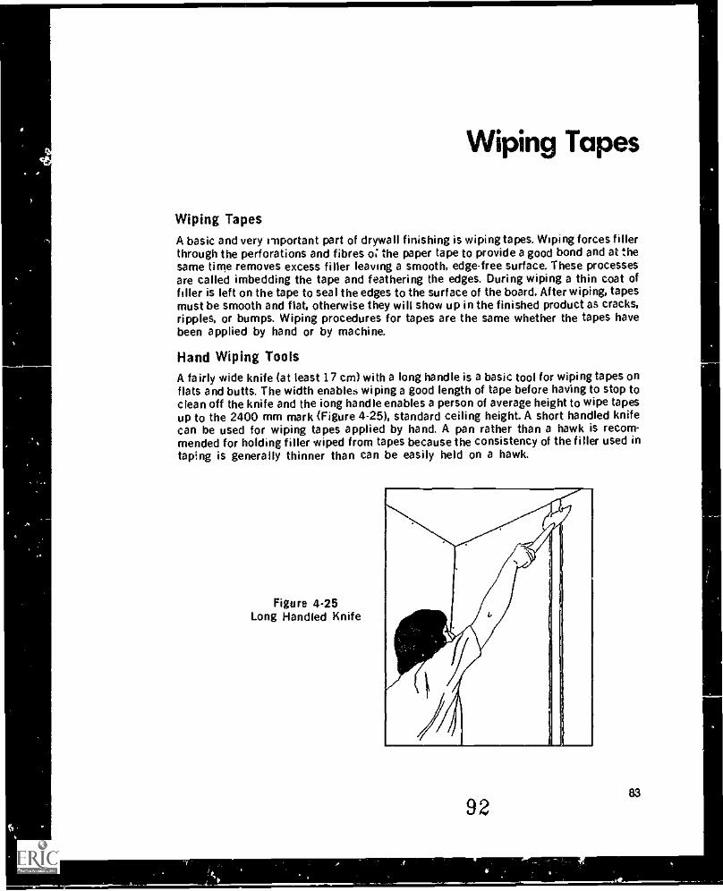
Wiping Tapes
Wiping TapesA basic and very important part of drywall finishing is wiping tapes. Wiping forces fillerthrough the perforations and fibres o the paper tape to provide a good bond and at thesame time removes excess filler leaving a smooth, edge-free surface. These processesare called imbedding the tape and feathering the edges. During wiping a thin coat offiller is left on the tape to seal the edges to the surface of the board. After wiping, tapesmust be smooth and flat, otherwise they will show up in the finished product as cracks,ripples, or bumps. Wiping procedures for tapes are the same whether the tapes havebeen applied by hand or by machine.
Hand Wiping ToolsA fairly wide knife (at least 17 cm) with a long handle is a basic tool for wiping tapes onflats and butts. The width enables wiping a good length of tape before having to stop toclean off the knife and the iong handle enables a person of average height to wipe tapesup to the 2400 mm mark (Figure 4-25), standard ceiling height. A short handled knifecan be used for wiping tapes applied by hand. A pan rather than a hawk is recom-mended for holding filler wiped from tapes because the consistency of the filler used intaping is generally thinner than can be easily held on a hawk.
Figure 4-25Long Handled Knife
9283
Module 4
In addition to the wide knife for wiping flats and butts, you should also have a 12 cmknife for angles and for tapes 30 cm or less, and a 10 cm knife for narrow places suchas under valances or beside pipes and window sills. A special angle knife may berequired for wiping angles less than 90°. It is also a good practice to carry tape withyou because some areas that are left untaped may be too small to warrant calling thetaper back.
Tools are available to simplify the wiping of angles, and they can be used with anymethod of taping. One tool called a roller (Figure 4-34) embeds the tape and the othertool, a flusher (Figure 4-35), removes the excess filler and feathers the edges. Thesetools speed up wiping and produce a uniform job that is pleasing to the eye. As with anytool, the quality of the job will depend upon the skill of the operator.
Angle tools are designed for square angles. even surfaces, and properly appliedwallboard; but they will adjust to minor imperfections.
Note that an angle can be rolled and then can be wiped either with a flusher or with aknife.
Geostai Points On WipingI. Butts. flats and short tapes are wiped with a knife. Angles are wiped with a knife
or with a combination of two angle tools called a roller and a flusher,2. Starting at a point betwken the two ends of tape, all tapes that are hand wiped
must be wiped in two directions to eliminate the problem of the tape wrinkling.Procedures for hand wiping butts, flats, and angles are given in this module.
3. The amount of pressure applied to the knife and the angle of the knife to thewallboard regulate the amount of pressure applied by the knife and thu.' theamount of filler removed. The angle of the knife will vary with its flexibility, butgenerally it should be close to 45° (Figure 4.26). The closer the angle is to 90° themore filler is removed from under the tape and the more chance there is of thetape dragging along the joint. The angle of the knife also regulates how much filleris left covering the top of the tape. As a knife is pulled along a tape:a. The tape is imbedded.b. Filler flows under the tape to fill in any dry spots.c. Excess filler is trapped between the knife and the wall. Some of it escapes be-
tween the blade and the wall, coating the tape and leaving feathered edges.All of these processes are desirable to produce a properly wiped tape.
4. When starting to wipe a new tape you will need a biz of filler on the knife to startthe skim coat on top of the tape.
5. The right amount of filler must be left under the tape. Too much filler under thetape will leave the tape too close to the top of the bevel and cause the tape toshow after the joint has been finished and sanded. Conversely, too little filler un-der the tape will leave dry spots that cause the tape to lift off the wall when thejoint is filled. To get the right amount make sure thr.: !wife blade is filed squareand the blade is held close to a 45° angle.
6. Too much filler must not be left on top of the tape because it will cause excessiveshrinkage. This shrinkage is difficult to cover and can also cause cracks on theedges owing to shrinkage of the filler around the tape.
84 r 01,0
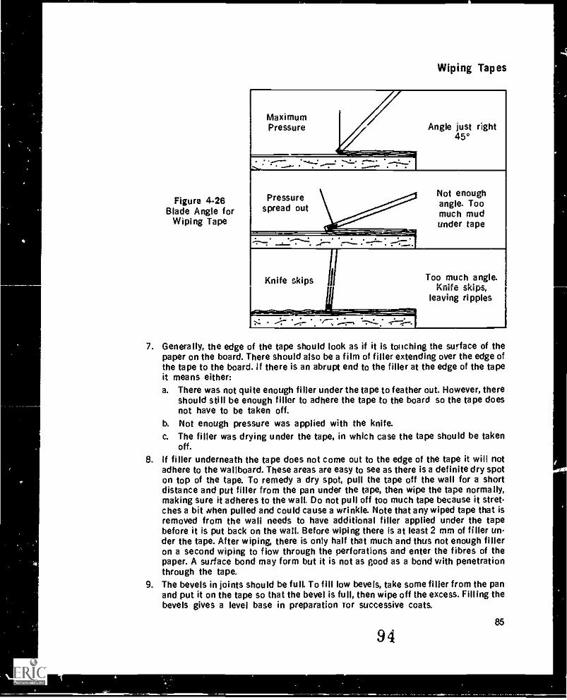
Figure 4-26Blade Angle for
Wiping Tape
Wiping Tapes
Angle just right45°
Pressurespread out
Not enoughangle. Toomuch mudunder tape
Knife skips I
. . 11 --.. '':':'
Too much angle.Knife skips,
leaving ripples
7. Generally, the edge of the tape should look as if it is touching the surface of thepaper on the board. There should also be a film of filler extending over the edge ofthe tape to the board. if there is an abrupt end to the filler at the edge of the tapeit means either:a. There was not quite enough filler under the tape to feather out. However, there
should still be enough filler to adhere the tape to the board so the tape doesnot have to be taken off.
b. Not enough pressure was applied with the knife.c. The filler was drying under the tape, in which case the tape should be taken
off.8. If filler underneath the tape does not come out to the edge of the tape it will not
adhere to the wallboard. These areas are easy to see as there is a definite dry spoton top of the tape. To remedy a dry spot, pull the tape off the wall for a shortdistance and put filler from the pan under the tape, then wipe the tape normally,making sure it adheres to the wall. Do not pull off too much tape because it stretches a bit when pulled and could cause a wrinkle. Note that any wiped tape that isremoved from the wall needs to have additional filler applied under the tapebefore it is put back on the wall. Before wiping there is at least 2 mm of filler under the tape. After wiping, there is only half that much and thus not enough filleron a second wiping to flow through the perforations and enter the fibres of thepaper. A surface bond may form but it is not as good as a bond with penetrationthrough the tape.
9. The bevels in joints should be full. To fill low bevels, take some filler from the panand put it on the tape so that the bevel is full, then wipe off the excess. Filling thebevels gives a level base in preparation ror successive coats.
9485
1
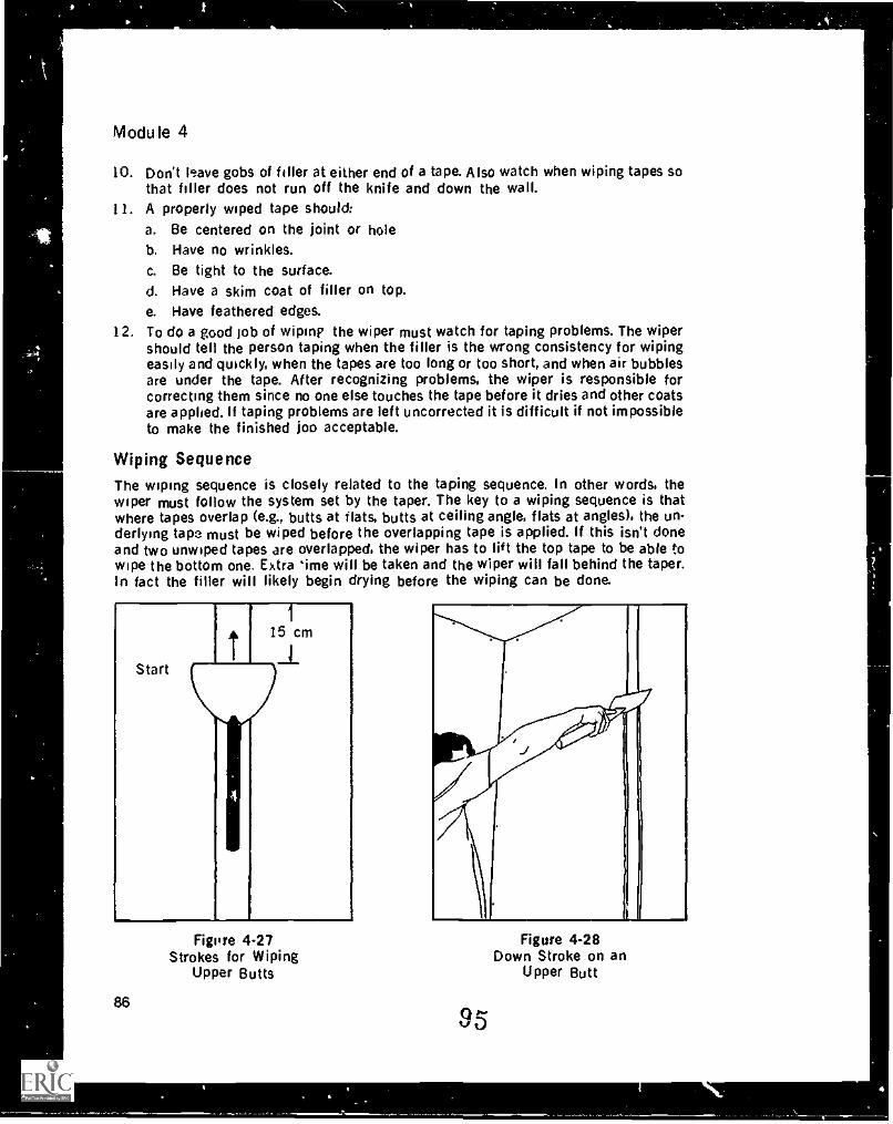
Module 4
10. Don't leave gobs of filler at either end of a tape. Also watch when wiping tapes sothat filler does not run off the knife and down the wall.
11. A properly wiped tape should:a. Be centered on the joint or holeb. Have no wrinkles.c. Be tight to the surface.d. Have a skim coat of filler on top.e. Have feathered edges.
12. To do a good job of wimp the wiper must watch for taping problems. The wipershould tell the person taping when the filler is the wrong consistency for wipingeasily and quickly, when the tapes are too long or too short, and when air bubblesare under the tape. After recognizing problems, the wiper is responsible forcorrecting them since no one else touches the tape before it dries and other coatsare applied. If taping problems are left uncorrected it is difficult if not impossibleto make the finished OD acceptable.
Wiping SequenceThe wiping sequence is closely related to the taping sequence. In other words, thewiper must follow the system set by the taper. The key to a wiping sequence is thatwhere tapes overlap (e.g., butts at flats, butts at ceiling angle, flats at angles), the un-derlying tape must be wiped before the overlapping tape is applied. If this isn't doneand two unwiped tapes are overlapped, the wiper has to lift the top tape to be able towipe the bottom one. Extra 'ime will be taken and the wiper will fall behind the taper.In fact the filler will likely begin drying before the wiping can be done.
Startt
I15 cma
Figure 4-27Strokes for Wiping
Upper Butts
86
Figure 4-28Down Stroke on an
Upper Butt
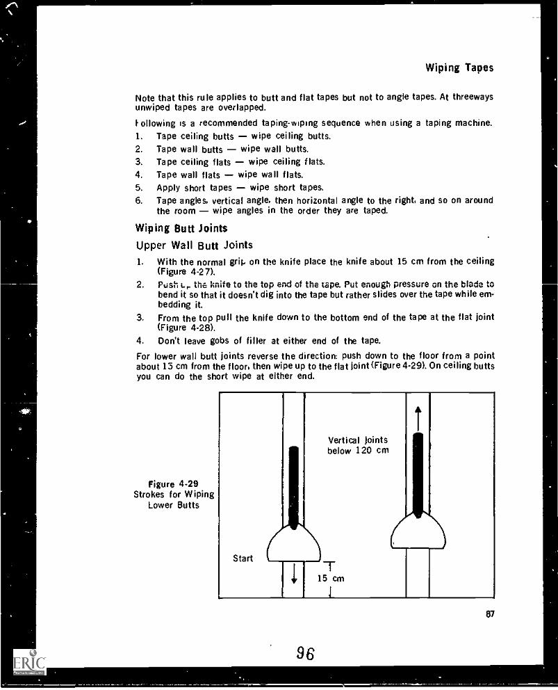
Wiping Tapes
Note that this rule applies to butt and flat tapes but not to angle tapes. At threewaysunwiped tapes are overlapped.
Following is a recommended taping-wiping sequence when using a taping machine.1. Tape ceiling butts wipe ceiling butts.2. Tape wall butts wipe wall butts.3. Tape ceiling flats wipe ceiling flats.4. Tape wall flats wipe wall flats.5. Apply short tapes wipe short tapes.6. Tape angles, vertical angle, then horizontal angle to the right, and so on around
the room wipe angles in the order they are taped.
Wiping Butt joints
Upper Wall Butt Joints1. With the normal grip on the knife place the knife about 15 cm from the ceiling
(Figure 4-27).2. Posh t.r. the knife to the top end of the tape. Put enough pressure on the blade to
bend it so that it doesn't dig into the tape but rather slides over the tape while em-bedding it.
3. From the top pull the knife down to the bottom end of the tape at the flat joint(Figure 4-28).
4. Don't leave gobs of filler at either end of the tape.
For lower wall butt joints reverse the direction: push down to the floor from a pointabout 13 cm from the floor, then wipe up to the flat joint (Figure 4-29). On ceiling buttsyou can do the short wipe at either end.
Figure 4-29Strokes for Wiping
Lower Butts
Start
r
1
Vertical Jointsbelow 120 cm
715 cm
i
1
96
87
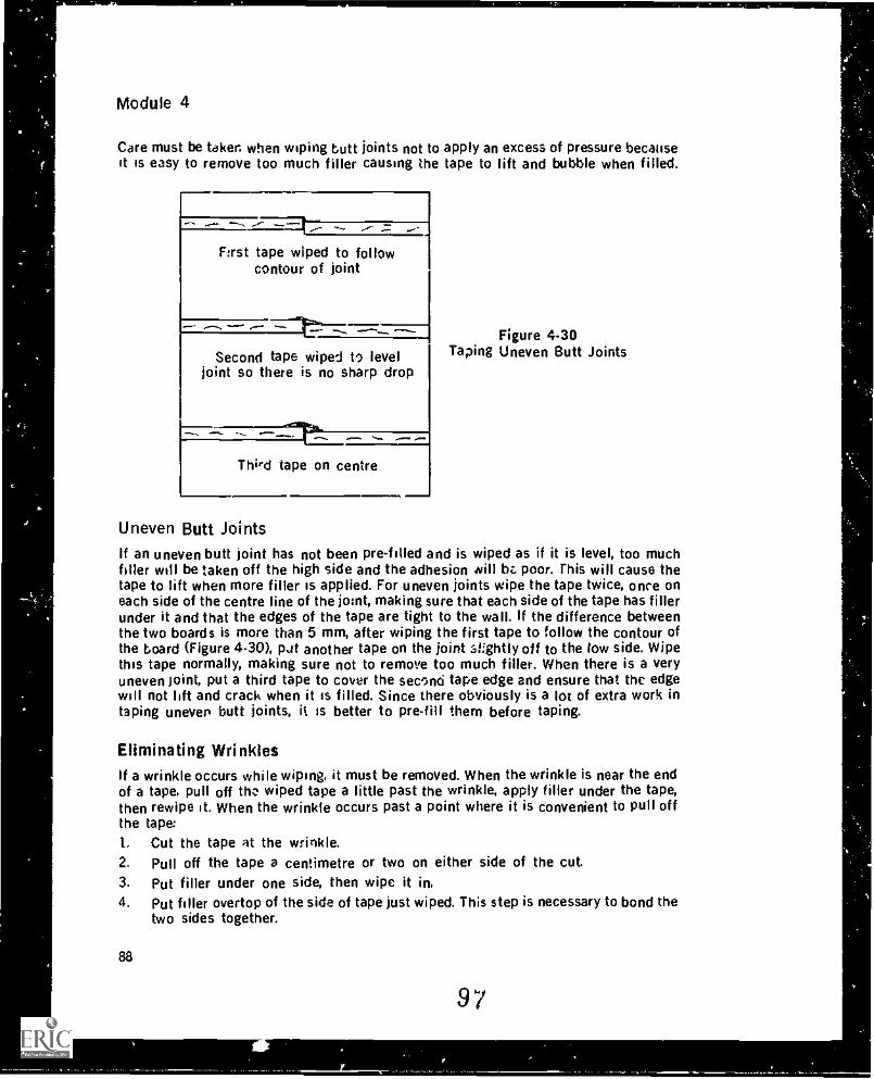
Module 4
Care must be taker. when wiping butt joints not to apply an excess of pressure becauseit is easy to remove too much filler causing the tape to lift and bubble when filled.
First tape wiped to followcontour of joint
iy,Second tape wiped to level
joint so there is no sharp drop
Third tape on centre
Figure 4-30Taping Uneven Butt Joints
Uneven Butt JointsIf an uneven butt joint has not been pre-filled and is wiped as if it is level, too muchfiller will be taken off the high side and the adhesion will bt poor. This will cause thetape to lift when more filler is applied. For uneven joints wipe the tape twice, once oneach side of the centre line of the joint, making sure that each side of the tape has fillerunder it and that the edges of the tape are tight to the wall. If the difference betweenthe two boards is more than 5 mm, after wiping the first tape to follow the contour ofthe board (Figure 4-30), pit another tape on the joint .si:ghtly off to the low side. Wipethis tape normally, making sure not to remove too much filler. When there is a veryuneven joint, put a third tape to cover the second tape edge and ensure that the edgewill not lift and crack when it is filled. Since there obviously is a lot of extra work intaping uneven butt joints, it is better to pre-fill them before taping.
Eliminating Wrinklesif a wrinkle occurs while wiping, it must be removed. When the wrinkle is near the endof a tape, pull off the wiped tape a little past the wrinkle, apply filler under the tape,then rewipe it. When the wrinkle occurs past a point where it is convenient to pull offthe tape:1. Cut the tape at the wrinkle.2. Pull off the tape a centimetre or two on either side of the cut.3. Put filler under one side, then wipe it in.4. Put filler overtop of the side of tape just wiped. This step is necessary to bond the
two sides together.
88
97
f
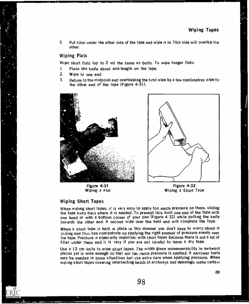
Wiping Tapes
5 Put filler under the other side of the tape and wipe it in. This side will overlap theother.
Wiping FlatsWipe short flats (up to 2 m) the same as butts. To wipe longer flats:1 Place the knife about mid-length on the tape.2. Wipe to one end.3 Return to the midpoint and overlapping the first wipe by a few centimetres wipe to
the other end of the tape (Figure 4-31).
it
4-4e- =
Figure 4.31Wiping a Flat
Figure 4.32Wiping a Short Tape
Wiping Short TapesWhen wiping short tapes, it is very easy to apply too much pressure on them, slidingthe tape away from where it is needed. To prevent this, hold one end of the tape withone hand or with a bottom corner of your pan (Figure 4-32) while pulling the knifetowards the other end. A second wipe over the held end will complete the tape.
When a short tape is held in place in this manner you don't have to worry about itsliding and thus can concentrate on applying the right amount of pressure evenly overthe tape. Pressure is especially important with short tapes because there is not a lot offiller under them and it is 'easy if you are not careful to leave a dry tape.
Use a 12 cm knife to wipe short tapes. The width given maneuverability in awkwardplaces yet is wide enough so that not too much pressure is applied. A narrower knifemay be needed in some situations but use extra care when applying pressure. Whenwiping short tapes covering intersecting beads at archways and openings, make certain
98
89
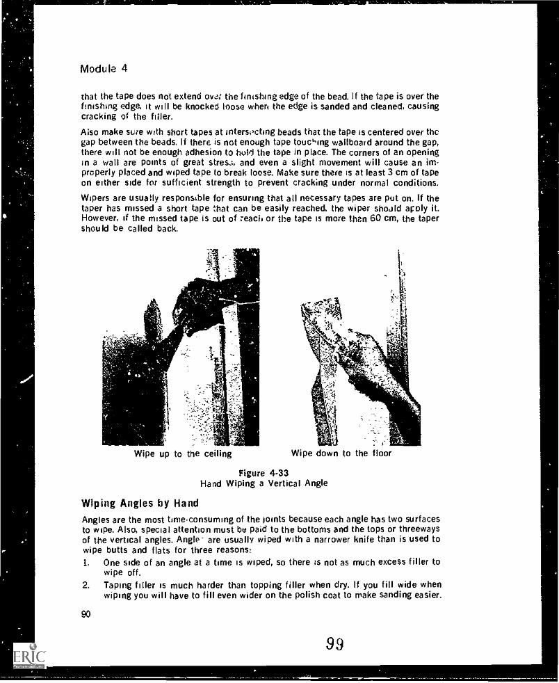
Module 4
that the tape does not extend ova: the finishing edge of the bead. if the tape is over thefinishing edge, it will be knocked loose when the edge is sanded and cleaned, causingcracking of the filler.
Also make sure with short tapes at intersicting beads that the tape is centered over thegap between the beads. If there is not enough tape toucking wallboard around the gap,there will not be enough adhesion to WO the tape in place. The corners of an openingin a wall are points of great stres.:, and even a slight movement will cause an im-properly placed and wiped tape to break loose. Make sure there is at least 3 cm of tapeon either side for sufficient strength to prevent cracking under normal conditions.
Wipers are usually responsible for ensuring that all necessary tapes are put on. If thetaper has missed a short tape that can be easily reached, the wiper should apply it.However, if the missed tape is out of :each or the tape is more than 60 cm, the tapershould be called back.
r.
-
Wipe up to the ceiling Wipe down to the floor
Figure 4-33Hand Wiping a Vertical Angle
Wiping Angles by HandAngles are the most time-consuming of the joints because each angle has two surfacesto wipe. Also, special attention must be paid to the bottoms and the tops or threewaysof the vertical angles. Angle- are usually wiped with a narrower knife than is used towipe butts and flats for three reasons:1. One side of an angle at a time is wiped, so there is not as much excess filler to
wipe off.2. Taping filler is much harder than topping filler when dry. If you fill wide when
wiping you will have to fill even wider on the polish coat to make sanding easier.
90
99
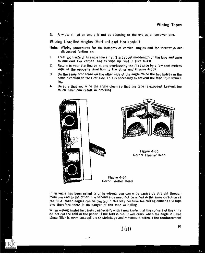
Wiping Tapes
3. A wider fill at an angle is not as pleasing to the eye as a narrower one.
Wiping Unrolled Angles (Vertical and Horizontal)Note: Wiping procedures for the bottoms of vertical angles and for threeways are
discussed further on.
1. Treat each side of an angle like a flat. Start about mid-length on the tape and wipeto one end. For vertical angles wipe up first (Figure 4-33).
2. Return to your starting point and overlapping the first wipe by a few centimetreswipe in the opposite direction to the other end (Figure 4-33).
3. Do the same procedure on the other side of the angle. Wipe the two halves in thesame direction as the first side. This is necessary to prevent the tape from wrinkl-ing
4. Be sure that you wipe the angle clean so that the tape is exposed. Leaving toomuch filler can result in cracking.
Figure 4.34Corny Roller Head
Figure 4.35Corner Flusher Head
if An angle has been rolled prior to wiping, you can wipe each side straight throughfrom .one end to the other. The second side need not be wiped in the same direction asthe fir ,t Rolled angles can be treated in this way because the rolling embeds the tapeand therefore there is no danger of the tape wrinkling.
When wiping angles be careful, especially with a new knife, that the corners of the knifedo not cut the told in the paper. If the fold is cut, it will crack when the angle is filledsince filler is more susceptible to shrinkage and movement without the reinforcement
100 91
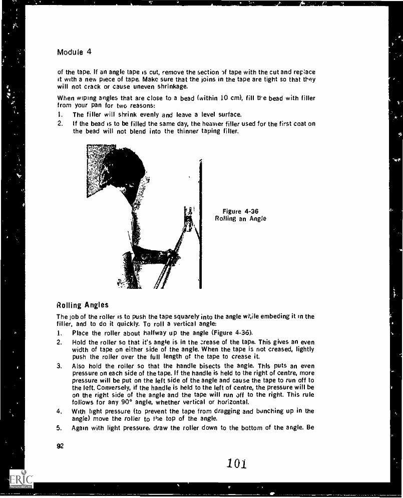
Module 4
of the tape. If an angle tape is cut, remove the section -if tape with the cut and reraceit with a new piece of tape. Make sure that the joins in the tape are tight so that tl qywill not crack or cause uneven shrinkage.
When wiping angles that are close to a bead (within 10 cm), fill tl-e bead with fillerfrom your pan for two reasons:1. The filler will shrink evenly and leave a level surface.2. If the bead is to be filled the same day, the heavier filler used for the first coat on
the bead will not blend into the thinner taping filler.
Figure 4-36Rolling an Angle
Rolling AnglesThe job of the roller is to Push the tape squarely into the angle wtile embeding it in thefiller, and to do it quickly. To roll a vertical angle:1. Place the roller about halfway up the angle (Figure 4-36).2. Hold the roller so that it's angle is in the :rease of the tape. This gives an even
width of tape on either side of the angle. When the tape is not creased, lightlypush the roller over the full length of the tape to crease it.
3. Also hold the roller so that the handle bisects the angle. This puts an evenpressure on each side of the tape. If the handle is held to the right of centre, morepressure will be put on the left side of the angle and cause the tape to run off tothe left. Conversely, if the handle is held to the left of centre, the pressure will beon the right side of the angle and the tape will run off to the right. This rulefollows for any 90° angle, whether vertical or horizontal.
4. With light pressure (to prevent the tape from dragging and bunching up in theangle) move the roller to the top of the angle.
5. Again with light pressure, draw the roller down to the bottom of the angle. Be
92
10.1
Wiping Tape:,
careful the roller doesn't touch the floor since it will pick up debris and distributeit throughout the angle.
6. With heavier pressure, make a second pass pushing up to the top, then down tothe bottom again.
7. Some finishers prefer tc make a final stroke up to the top of the angle so they arein a position ready to start the horizontal angle.
8. When filler starts to build i.p on the roller Op it in water and swirl it around toremove the filler. Also put the roller in water when it it, dot in use to prevent fillerfrom drying in it.
Basically the same procedures as those for vertical angles apply to horizontal angles.However, extra care must be taken with horizontal angles to avoid uragging the tape;the horizontal angle tapes are uswily longer than vertical ones and they have a greatertendency to drag.
Problems When Rolling AnglesIf angle tapes drag too much it means either that :co much pressure is put on the rolleron the first pass or that the roller is started from one end rather than from the middle.Note that if a tape is dragged too much, the tape can fold and catch on the leading edgeof the roller.
If a tape is rolled to one side, it should Le pulled off from the nearest end past the pointwhere it sta, ted to go to one side. Soule rolled tapes that pulleo off do not requireadditional filler. whereas others do to give an adequate bond. The person rol'ing mustmake a judgement here. Filler can be placed under the to -.e by banging tie roller lightlyinto the angle so that filler dislodges from the roller and L teft in the angle. Thisprocedure also can b used to place filler on a dry spot under the tape.
If a long horizontal tape that hat. been 'oiled has a problem 'n the middle (i.e., therewould be a lot of tape to WI off); or if a tape that is too high to reach convenientlyneeds repair, they can be corrected by placing a lew tape over the faulty one. The firsttape should be rolled to bond it to the r ail, and the second tape rolled to bond it to thefirst tape.
Short angle tapes tend to slide with the roller. Roll these by first pressing the tape intothe angle with the roller ar I then rolling the tape with light pressure until it no longerslides. Finally apply more 1.essure to properly imbed the tape.
Flushing AnglesAfter the angles are rolled they are flushed. The flushing should leave a thin film offiller covering the tape and a feathered edge. There should be no gaps or large airpockets in the filler.
A flusher is either hinged in the middle or made of a springy metal bent slightly greaterthan Wallowing it to deal with small deviations from 90°. However, if the deviationsare too large tne edges of the flusher or the centre will dig into the tape and strip it offtne angle. Note that flushers are not meant to be used on angles that by design aregreater or less than 90°. Also, flushers should not be used where one edge of a 90°angle is in contact with a metal head, concrete, or other hard surface. Either of thesesurfaces will damage the flusher.
10293
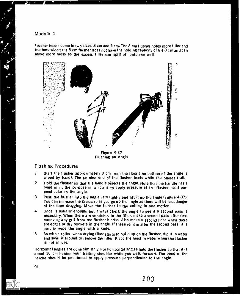
r
f
;.
Module 4
rusher heads come in two sizes. 8 cm and 5 cm. The 8 cm flusher holds more filler andfeathers wider; the 5 cm flusher does not have the holding capacity of the 8 cm and canmake more mess as the excess filler can spill off onto the wall.
Figure 4-37Flushing an Angle
Flushing ProceduresI Start the flusher approximately 8 cm from the floor (the bottom of the angle is
wiped by hand). The pointed end of the flusher leads while the blades trail.2. Hold the flusher so that the handle bisects the angle. Note that the handle has a
bend in it, the purpose of which is to apply pressure at the flusher head per-pendicular to the angle.
3 Push the flusher into the angle very lightly and lift it up the angle (Figure 4-37).You can increase the pressure as you go up the rngle as there will be less dangerof the tape dragging. Move the flusher to the ceiling in one motion.
4 Once is usually enough, but always check the angle to see if a second pass isnecessary. When there are scratches in the filler, make a second pass after firstremoving any grit from the flusher blades. Also make a second pass when thereare edges or dry pockets in the angle. If these remain after the second pass, it isbest to wipe the angle with a knife.
5 As with a roller. when drying filler starts to build up on the flusher, dip it in waterand swirl it around to remove the filler. Place the head in water when the flusheris not in use.
Horizontal angles are done similarly. For horizontal angles hold the flusher so that it isabout 30 cm behind your trailing shoulder while you walk forward. The bend in thehandle should be positioned to apply pressure perpendicular to the angle.
94
103
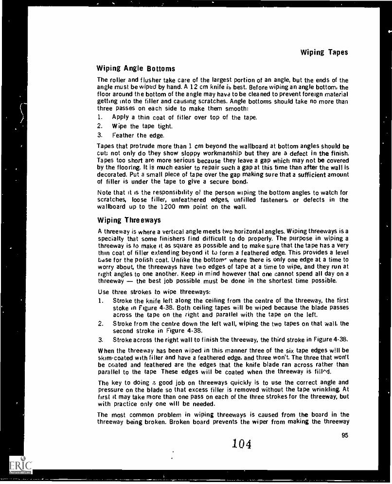
Wiping Tapes
Wiping Angle BottomsThe roller and flusher take care of the largest portion of an angle, but the ends of theangle must be wiped by hand. A 12 cm knife is best. Before wiping an angle bottom, thefloor around the bottom of the angle may hava to be cleaned to prevent foreign materialgetting into the filler and causing scratches. Angle bottoms should take no more thanthree passes on each side to make them smooth:1. Apply a thin coat of filler over top of the tape.2. Wipe the tape tight.3. Feather the edge.
Tapes that protrude more than 1 cm beyond the wallboard at bottom angles should becut; not only do they show sloppy workmanship but they are a defect in the finish.Tapes too short are more serious because they leave a gap which may not be coveredby the flooring. It is much easier to repair such a gap at this time than after the wall isdecorated. Put a small piece of tape over the gap making sure that a sufficient amountof filler is under the tape to give a secure bond.
Note that it is the responsibility of the person wiping the bottom angles to watch forscratches, loose filler, unfeathered edges, unfilled fasteners, or defects in thewallboard up to the 1200 mm point on the wall.
Wiping ThreewaysA threeway is where a vertical angle meets two horizontal angles. Wiping threeways is aspecialty that some finishers find difficult to do properly. The purpose in wiping athreeway is to make it as square as possible and to make sure that the tape has a verythin coat of filler extending beyond it to form a feathered edge. This provides a levelbese for the polish coat. Unlike the bottom where there is only one edge at a time toworry about, the threeways have two edges of tape at a time to wipe, and they run atright angles to one another. Keep in mind however that one cannot spend all day on athreeway the best job possible must be done in the shortest time possible.
Use three strokes to wipe threeways:1. Stroke the knife left along the ceiling from the centre of the threeway, the first
stoke in Figure 4-38. Both ceiling tapes will be wiped because the blade passesacross the tape on the right and parallel with the tape on the left.
2. Stroke from the centre down the left wall, wiping the two tapes on that wall, thesecond stroke in Figure 4.38.
3. Stroke across the right wall to finish the threeway, the third stroke in Figure 4-38.
When the threeway has been wiped in this manner three of the six tape edges wall beskim-coated with filler and have a feathered edge, and three won't. The three that won'tbe coated and feathered are the edges that the knife blade ran across rather thanparallel to the tape These edges will be coated when the threeway is filled.
The key to doing a good job on threeways quickly is to use the correct angle andpressure on the blade so that excess filler is removed without the tape wrinkling. Atfirst it may take more than one pass on each of the three strokes for the threeway, butwith practice only one will be needed.
The most common problem in wiping threeways is caused from the board in thethreeway being broken. Broken board prevents the wiper from making the threeway
10495
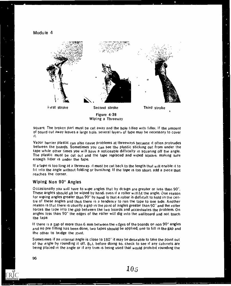
Module 4
i-irst stroke Second stroke
Figure 4.38Wiping a Threeway
Third stroke
square The broken part must be cut away and the hole filleo with filler. If the amountof board cut away leaves a large hole, several layers of tape may be necessary to coverit.
Vapor barrier plastic can also cause problems at threeways because it often protrudesbetween the boards. Sometimes you can see the plastic sticking out from under thetape while other times you will have a noticeable difficulty in squaring off the angle.The plastic must be cut out and the tape replaced and wiped square, making sureenough filler is under the tape.
If a tape is too long at a threeway, it must be cut back to the length that will enable it tofit :nto the angle without folding or bunching. If the tape is too short, add a piece thatreaches the corner.
Wiping Non 90° AnglesOccasionally you will have to wipe angles that by design are greater or less than 90'.These angles should all be wiped by hand, even if a roller will fit the angle. One reasonfor wiping angles greater than 90° by hand is that a roller is difficult to hold in the centre of these angles and thus there is a tendency to run the tape to one side. Anotherreason is that there is usually a gap in the joint of angles greater than 90" and the rollerforces the tape into the gap between the two boards and accentuates the problem. Onangles less than 90" the edges of the roller will dig into the wallboard and not touchthe tape.
If there is a gap of more than 6 mm between the Edges of the boards on non 90° anglesand no pre-filling has been done, two tapes should be applied, one to fill in the gap andthe other to bridge the pint.
Sometimes if an internal angle is close to 180" it may be desirable to take the point outof the angle by rounding it off. But. before doing so, check to see if any cabinets arebeing placed in the angle or if any trim is being used that would prohibit rounding the
96
105
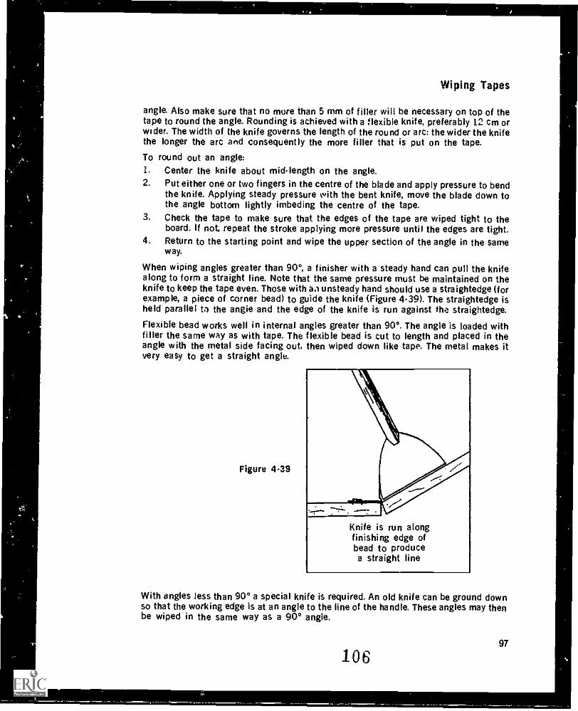
Wiping Tapes
angle. Also make sure that no more than 5 mm of filler will be necessary on top of thetape to round the angle. Rounding is achieved with a flexible knife, preferably 12 cm orwider. The width of the knife governs the length of the round or arc: the wider the knifethe longer the arc and consequently the more filler that is put on the tape.
To round out an angle:1. Center the knife about midlength on the angle.2. Put either one or two fingers in the centre of the blade and apply pressure to bend
the knife. Applying steady pressure with the bent knife, move the blade down tothe angle bottom lightly imbeding the centre of the tape.
3. Check the tape to make sure that the edges of the tape are wiped tight to theboard. If not, repeat the stroke applying more pressure until the edges are tight.
4. Return to the starting point and wipe the upper section of the angle in the sameway.
When wiping angles greater than 90°, a finisher with a steady hand can pull the knifealong to form a straight line. Note that the same pressure must be maintained on theknife to keep the tape even. Those with ao unsteady hand should use a straightedge (forexample, a piece of corner bead) to guide the knife (Figure 4.39). The straightedge isheld parallel to the angie and the edge of the knife is run against the straightedge.
Flexible bead works well in internal angles greater than 90°. The angle is loaded withfiller the same way as with tape. The flexible bead is cut to length and placed in theangle with the metal side facing out, then wiped down like tape. The metal makes itvery easy to get a straight angle.
Figure 448
Knife is run alongfinishing edge ofbead to producea straight line
With angles less than 90° a special knife is required. An old knife can be ground downso that the working edge is at an angle to the line of the handle. These angles may thenbe wiped in the same way as a 90° angle.
10697
Module 4
Cleanup After Wiping
Whenever wiping tapes, take care to leave a clean job. This holds for the taped joints,the walls, ceilings, floors, and also for yourself. Remember that wiping prepares thefoundation for the rest of the filling. The cleaner and smoother the foundation, theeasier it will be to produce a smooth flat finish. A clean wiping job shows your skill as afinisher.
It is the responsibility of the wiper to check the entire wall for splatters or runs offiller. Wher these are removed while wet, they leave only a thin film of filler that posesno problem. On the other hand, if a lump of filler is let dry and must be sanded, thepaper may be roughed up and will then have to be coated to be made smooth again, allof which is a waste of time. Get into the habit of checking the walls before you leave aroom and removing any spatters or runs while they are wet.
Dry lumps of filler are especially a problem when filling machines are used to fi'd theangles. Machines do not compensate for a lump of dry filler; they either go over thelump, accentuating it with more filler pr drag the dry filler along the angle or joint. Ataping filler lump is made of a harder compound than topping filler. When the lump issanded after the topping filler is applied, the topping filler will be removed from aroundthe lump creating more problems. The obvious solution is to leave the walls clean tostart with.
Other parts of the room should ilso be kept clean. Floors can be kept clean by placingscrap filler on old bags or plastic positioned where they won't be stepped on. Windowsills, windows, doors, door frames, and heat registers should also be kept clean. In fact,after wiping the only place where filler should be is on the joints, angles, short tapes,and beads.
Keep yourself clean too. For example, wipe your knife on the pan, not on your pants.
98107
Wiping Tapes
Wiping Butts and Flats Sleuth Sheet
Problem
Tape wrinkles.
Bubbles on the sur-face of the tape.
Not enough mud tofill.
No mud protrudingfrom edge of tape.
Mud falling on wall.
Cause
1. Uneven pressure whenwiping.
2 Uneven amount of mud under tape owing to unevenedges of board.
3. Wiping tape from one endand not from middle.
4. Wiping angles up on oneside and down on the other.
5. Tape not put on straight.
6. Something under tape.
1. Knife skips on the tape.
1. Not enough mud undertape.
2. Bevel too wide.
3. Mud too thick.
1. No mud under tape.
1. Mud building up on bladesof knife.
2. Knife too narrow.
3. Too much mud under tape(hand taping).
4. Mud too thin.
1.
2.
3.
4.
5.
6.
Solution
Hold knife at angle close to90° and develop wrist andarm muscles.Wipe one side, then theother.
Start in middle of tape andwork to the ends.Wipe both sides of angle inthe same direction.Straighten tape beforewiping.Remove object under tape,remud, and wipe back inplace.
1. Knife is held too close to90°.
2. The pressure on the knife isnot even.
1. Put mud in area and re-wipe.
2. Put mud in area and re-wipe.
3. Ask the taper to thin themud and fill bevel and re-wipe.
1. Pull tape back, put mud un-der and rewipe.
1. Hold knife so that bottomedge is leading edge.
2. Clean knife more often. Usewider !mite.
3. Ask the taper to adjust gatefor less mud.
4. Ask the taper t thickenmud.
99
108
1,
Module 4
Wiping Butts and Flats Sleuth Sheet
Problem
Tape appears tr,have no mud underit.
Tape ,appears to besitting too high.
Knife pulls tapesaway from wall at in.tersecting joints.
Mud under tape hasbecome too stiff towipe.
Cause
1. No ..iud under tapeapplied.
2. Wiped too hard.
3. Mud too thin.
4. "..ineven board.
1. Mud too thick.
when
2. Not wiped hard enough.
3. Knife not filed to squareedge.
1. Previously wiped tapes notwipes tight enough.
2. Angle of knife too great
1. Chemical reaction be-tween board and filler.
2. Chemical reaction betweenmixed fillers.
3. Tape has been left too long.
Solution
1. a. Check with taper.b Remud and wipe.
2. a. Decrease angle of bladeto wall.
b. Decrease pressure onknife.
3. Ask the taper to fhif:kenmud.
4. Wipe high side then lowside, filling in low side.
1. Thin the mud then re-mudand wipe.
2. a. Increase pressure onknife.
b. Increase angle of knife.3. File knife with single cut
mill bastard file to achievesquare edge.
1. Rewipe previous tape afterre-mudding.
2. Decrease angle of blade; increase pressure.
1. Remove tape; contact per-son in charge; cnange offiller required.
2. Clean pails, discard mixedmaterial and mix new batchusing one type of filler.
3. Remove tape, scrape off dryfiller, re-tape.
100 109
Wiping Tapes
Wiping Angles Sleuth Sheet
Problem Cause Solution
Flusher pulls tape 1. Angle not 90'. 1. Wipe by hand.along angle. 2. Tape not tightly rolled. 2. Replace tape, roll again,
then re-flush.1 Flusher started too close to 3. Flusher should be started
emi of tape. about 8 cm from end oftape.
t:. Too much pressure. 4. Decrease pressure onflusher.
5. Wrong end of flusher point- 5. Pointed end of flushered forward. leads, blades trail.
Angle has wallboard 1 Design of building. 1. Roll lightly on the concreteon one side, con- and wipe by hand.crete or metal on 2. Roll tlg:)t on metal andother. wipe by hand.
Angles not square. 1. Knife rounded on corners. 1. File knife square.2. Tape not properly craased. 2. a. Crease tape before ap-
plying to angle.b. Use creasing wheel in
angle.3. Mud too thick. 3. Mud should be thinner than
mud for flat tapes.4. Ar,gle not rolled tight. 4. Put more pressure on
roller.
A rigLs cut in corner. 1. Corners of knife too point- 1. Blunt corners of knife oned. cement or file; retape
angles.2. Shoe on flusher worn out. 2. Repair flusher.
Wrinkle in angle. 1. Opposite sides of angle 1. Wipe top or bottom in samewiped in two differentdirections.
direction both sides.
2. Tape not rolled precisely in 2. Hold roller to bisect angle.corner. Remove tape and roll
properly.
101
110
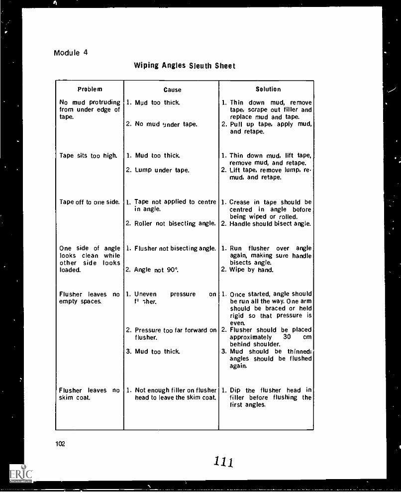
.,
Module 4
Wiping Angles Sleuth Sheet
Problem Cause Solution
No mud protruding 1. Mud too thick. 1. Thin down mud, removefrom under edge of tape, scrape out filler andtape. replace mud and tape.
2. No mud under tape. 2. Pull up tape, apply mud,and retape.
Tape sits too high. 1. Mud too thick. 1. Thin down mud, lift tape,remove mud, and retape.
2. Lump under tape. 2. Lift tape, remove lump, remud, and retape.
Tape off to one side. 1. Tape not applied to centre 1. Crease in tape should bein angle. centred in angle before
being wiped or rolled.2. Roller not bisecting angle. 2. Handle should bisect angle.
One side of angle 1. Flusher not bisecting angle. 1. Run flusher over anglelooks clean while again, making sure handleother side looks bisects angle.loaded. 2. Angle not 900. 2. Wipe by hand.
Flusher leaves no 1. Uneven pressure on 1. Once started, angle shouldempty spaces. fi >her. be run all the way. One arm
should be braced or heldrigid so that pressure iseven.
2. Pressure too far forward on 2. Flusher should be placedflusher. approximately 30 cm
behind shoulder.3. Mud too thick. 3. Mud should be thinned;
angles should be flushedagain.
Flusher leaves no 1. Not enough filler on flusher 1. Dip the flusher head inskim coat. head to leave the skim coat. filler before flushing the
first angles.
102
in
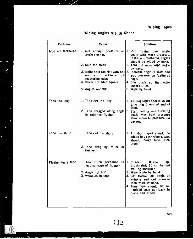
Wiping Tapes
Wiping Angles Sleuth Sheet
Problem
Mud not feathered.
Cause
1. Not enough pressure on
Solution
1. Run flusher over angleangle flusher. again with more pressure.
2. Mud too thick.
If still not feathered, anglesshould be wiped by hand,
2. Thin out mud; wipe angleby hand.
3. Knife held too flat with not 3. Increese angle of knife andenough pressure on put pressure on featheredfeathering edge. edge.
4. Blade not filed square. 4. File blade so that edgeshears filler.
5. Angles not 90°. 5. Wipe by hand.
Tape too long. 1. Tape cut too long. 1. All long tapes should be cutto within 5 mm of end ofjoint.
2. Tape dragged along angle 2. Start rolling and flushingby roller or flusher. angle with light pressure
then increase pressure onpasses.
Tape too short. 1. Tape cut too short. 1. All short tapes should beadded to by the wipers. whoshould carry tape withthem.
2. Tape drag by roller orflusher.
Flusher tears tape. 1. Too much pressure on 1. Position flusher ap-leading adge of flusher proximately 30 cm behind
trailing shoulder.2. Angle not 90°. 2. Wipe angle by hand.3. Wrinkles in tape. 3. Lift flusher off angle at
wrinkle and cut wrinkle.then wipe by hand.
4. Torn tape should be remudded then put back inplace and wiped.
103
112
Module 4
EXERCISE
1. What type of knife should be used for wiping flat and butt tapes applied by hopperor machine?
2. How do you eliminate the problem of tape wrinkling?3. What regulates the amount of filler left under a tape when wiping?4. If filler does not reach the edge of the tape, what needs to be done?5. List five characteristics of a properly wiped tape.6. Who is responsible for correcting taping problems?7. If you have cut a tape to remove a wrinkle and have wiped one side down, what
must be done before wiping the other side?8. Why is the pressure applied to a short tape especially important?9. How much tape is required on either side of a gap for proper adhesion?
10. How long should a missed tape be to justify calling the taper back?11. What size knife is generally used for wiping angles?12. How are wrinkles avoidea when wiping unrolled arzgoe tapes?13. Why is it important not to tear wiped angle tapes in the centre?14. How should a roller and a flusher be held in relation to the angle?15. What happens if too much pressure is applied to the roller on the first pass?16. What will happen if the handle of the roller is held to the right of centre of the
angle?
17. What is the preferred size of flusher for wiping angles?18. dry pockets persist after a second pass with the flusher, what should be done?19. How far beyond the wallboard can tape extend and still be acceptable?20. at are the other responsibilities of the person wiping the bottoms of flushed
21. How many strokes are required to wipe a threeway?22. How many strokes should it take to wipe the bottom of an angle?23. Why is it best not to use a roller when wiping angles greater than 90°?24. What factors must be considered before angles are rounded?25. What are two ways of ensuring that angles greater than 90° are straight?
104
113
a
FillingMODULE 5
INTRODUCTION
Filling is the test of the drywall finisher to produce quality work. it is here where thefinisher's skill shows up most. Besides using hand tools skillfully, the finisher alsomust have a knowledge of filling compounds and how they are affected by temperatureand humidity. Other factors that have a baring on a good filling job are the boarding,beading and taping that are done before the filling begins. Even the best finishers willhave a difficult time turning out a quality filling job if the procedures that precedefilling have been done incorrectly.
Filling and sanding are the finishing touches to drywall surfaces. When completed thedrywall job should have fasteners tilled flush, straight bead edges and full beads, buttsand flats filled with maximum rise of 2 mm in 1200 mm, angles square, all edgesfeathered, and all filler surfaces smooth and blemish-free.
The Right Filler For the JobFour types of filler can be used for filling. taping, topping, all-purpose, and fast-setting.Taping filler should be used only for first coating since it has a lot of glue and driesvery hard making it difficult to sand. In addition, the fibres it taping filler make sand-ing it a higher health risk than sanding topping filler. The strong bonding of taping fillermakes it ideal for a first coat on fills less than 2 mm deep. Fills deeper than this willcheck or crack.
Since topping fillers have a high rate of shrinkage, they are mainly used for final coats.However, some premix topping fillers have a unique gel stage which considerablyreduces the amount of shrinkage making them suitable for all filling coats. These arenot fast-setting materials because they do not rely on crystal growth. Generally though,topping fillers are used for skim-coating on a surface to make it smooth. Because top-ping fillers are sanded, they do not contain as many fibres as taping filler.
All-purpose fillers can be used for all taping and filling coats but because they are for-mulated for general use, they do not perform as well as taping fillers do for taping ortopping fillers do for final coats.
Fast-setting filler is best suited for deep fills because its setting action produces ex-pansion of the filler and eliminates shrinkage. Since fast-set has a tendency to producean overfill, it is desirable to underfill with it to allow for expansion. Fast-set should notbe used for a finishing coati it should have a skim coat of limestone-based filler toprepare it for paint.
105
I 1 4
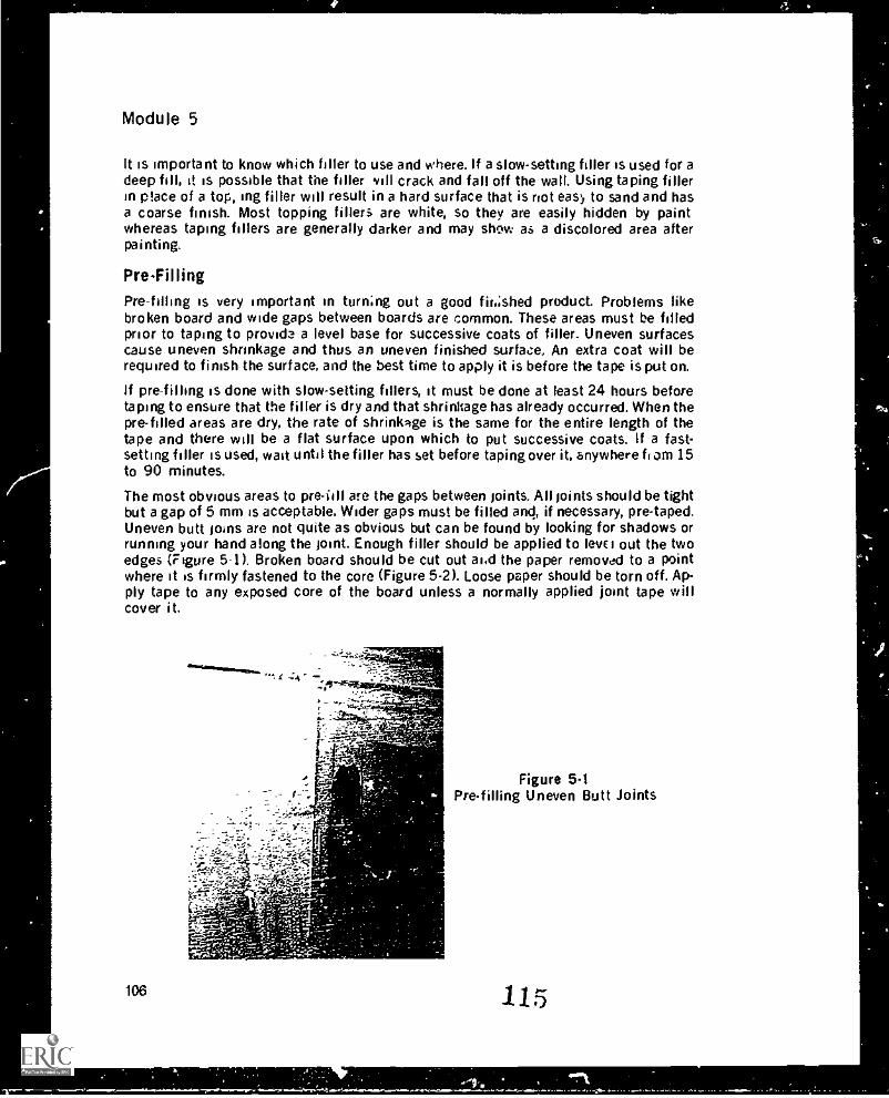
Module 5
It is important to know which filler to use and where. If a slow-setting filler is used for adeep fill, it is possible that the filler sill crack and fall off the wall. Using taping fillerin place of a top, mg filler will result in a hard surface that is riot easy to sand and hasa coarse finish. Most topping fillers are white, so they are easily hidden by paintwhereas taping fillers are generally darker and may show as a discolored area afterpainting.
Pre-Filling
Pre-filling is very important in turning out a good f ihished product. Problems likebroken board and wide gaps between boards are common. These areas must be filledprior to taping to provide a level base for successive coats of filler_ Uneven surfacescause uneven shrinkage and thus an uneven finished surface.. An extra coat will berequired to finish the surface, and the best time to apply it is before the tape is put on.
If pre-filling is done with slow-setting fillers, it must be done at least 24 hours beforetaping to ensure that the filler is dry and that shrinkage has already occurred. When thepre-filled areas are dry, the rate of shrinkage is the same for the entire length of thetape and there will be a flat surface upon which to put successive coats. If a fast-setting filler is used, wait until the filler has set before taping over it, anywhere tram 15to 90 minutes.
The most obvious areas to pre -fill are the gaps between joints. All joints should be tightbut a gap of 5 mm is acceptable. Wider gaps must be filled and, if necessary, pre-taped.Uneven butt joins are not quite as obvious but can be found by looking for shadows orrunning your hand along the joint. Enough filler should be applied to level out the twoedges (Figure 5-1). Broken board should be cut out ai.d the paper removed to a pointwhere it is firmly fastened to the core (Figure 5-2). Loose paper should be torn off. Ap-ply tape to any exposed core of the board unless a normally applied joint tape willcover it.
:15_
r vd.r.f.c4
;-;
106
Figure 5.1Pre-filling Uneven Butt Joints
115
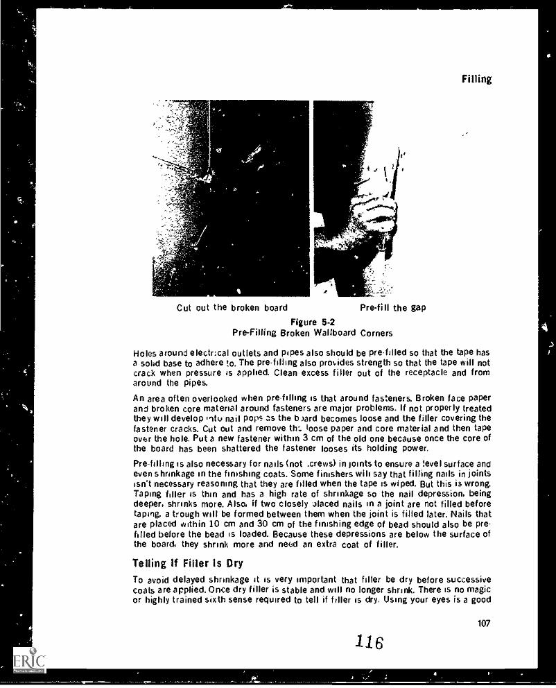
Filling
Cut out the broken board
A
Pre-fill the gap
Figure 5-2Pre-Filling Broken Wallboard Corners
Holes around electrical outlets and pipes also should be pre-filled so that the tape hasa solid base to adhere to. The pre-filling also provides strength so that the tape will notcrack when pressure is applied. Clean excess filler out of the receptacle and fromaround the pipes.
An area often overlooked when pre-filling is that around fasteners. Broken face paperand broken core material around fasteners are major problems. If not properly treatedthey will develop iitu nail pops as the b )ard becomes loose and the filler covering thefastener cracks. Cut out and remove tin loose paper and core material and then tapeover the hole. Put a new fastener within 3 cm of the old one because once the core ofthe board has been shattered the fastener looses its holding power.
Pre-filling is also necessary for nails (not .crews) in joints to ensure a level surface andeven shrinkage in the finishing coats. Some finishers WI!, say that filling nails in jointsisn't necessary reasoning that they are filled when the tape is wiped. But this is wrong.Taping filler is thin and has a high rate of shrinkage so the nail depression, beingdeeper, shrinks more. Also, if two closely 4laced nails in a joint are not filled beforetaping, a trough will be formed between them when the joint is filled later. Nails thatare placed within 10 cm and 30 cm of the finishing edge of bead should also be pre-filled before the bead is loaded. Because these depressions are below the surface ofthe board, they shrink more and need an extra coat of filler.
Telling If Filler Is DryTo avoid delayed shrinkage it is very important that filler be dry before successivecoats are applied. Once dry filler is stable and will no longer shrink. There is no magicor highly trained sixth sense required to tell if filler is dry. Using your eyes is a good
107
116
Module 5
start. Filler, when put on the wall, is shiny from the moisture. As it dries, it dulls andturns white or to its color in powdered form. When watching filler dry, becomes ob-vious that it dries from the shallowest to the deepest fill. Bead dries I.. closest to thefinishing edge of the bead, flats dry last in the middle of the joint, butt joints just toeither side of the tape, and angles in the apex of the angle. Therefore, when checking afill to see if it is dry, look at the area where the fill is the deepest. The second test is thetouch test. Dry filler is hard, and when tapped lightly with a fingernail no mark is left onthe surface. The wetter the filler the deeper the mark. Again, this test is done where thefill is deepest.
A moisture meter can be used to check the moisture content of filler. Wet filler willregister from 8 per cent upward. Dry filler will register from 0 to 6 per cent. Again, thereadings should be taken where the fill is deepest. Also make sure that the prongs onthe meter do not contact metal because this will produce a false reading.
Drying charts are available (see the example at the end e Module 8) that estimate thedrying time for filler under given temperature and humdity conditions. Rememberthough that the drying times on the charts are only estimates and should be confirmedby the sight and touch test.
Types Of Filler CoatsThe deciding factor in determining how many coats are required to properly finishfasteners, flats, butts, angles, or bead is what kind of finish will be put on the wall. Thisinformation can be found in the architect's finish schedule or blueprints, or by askingthe person in charge of the site. When a complete set of coats is made such as onbeads and fasteners, it generally takes two coats to level out or "load" the areas and athird to finish or polish the surface.The industry standard for coats of filler for a paint finish is:
Fasteners 3 coatsFlats 2 coatsButts 2 or 3 coatsAngles 1 coatBead 3 coats
The industry standard for coats of filler for texturing is:Fasteners 2 coatsFlats 1 or 2 coatsButts 2 coatsAngles no coats if wiped properlyBead 2 coats
First Coat (Loading Coat)The first i-oat on fasteners, butts and bead is also called the loading coat. The first coatdeposits the greater part of the fill applied during the several coats of the fillingprocess. A thick mix of filler is used which reduces shrinkage. When removing the ex-cess fill, the angle of the blade is held at less than 45 degress to the wall.
AlthQugh the amount of filler that should be left after the first coat varies with the typeof filler, the following general rules apply:
108
11 7
Filling
Powdered fillers usually shrink the most and so the joints and beads should beleft slightly over full.Premix fillers usually shrink less and so a level fill is desirable.Fast-setting fillers expand and so the fill should be slightly hollow.
Note that to know accurately the amount of shrinkage or expansion of a filler, the fillerhas to be tested under job conditions.
Because fillers used for the first coat dry to a hard surface the fill must be narrow andthe surface should not be ripplcd or ridged. Small air holes in the surface are not ofgreat concern on the first coat.
Second CoatThe second coat on fasteners, butts, and bead must accomplish two things:
Fill any shrinkage from the first coat.Form a smooth surface in preparation for a third or polish coat.
Flats do not receive a !oading coat. so the first coat on flats is what is being called herea second coat.
Filler for the second coat is mixed thinner than that for the first coat because thesecond coat fill, having much less depth than the first coat, has little shrinkage. Thethinner filler is necessary to provide a smooth surface. Topping filler is commonly usedfor the second coat because it not only produces a smooth finish, but makes sandingthe final coat easier. The second coat should be wider than the first coat. be smooth,and be blemish-free.
The angle of the blade is held at 45 degrees for the second coat.
Third CoatThe third coat, also known as the final coat or polish coat, on fasteners, joints and beadshould:
Completely cover the previous coats.Leave a smooth, flat, level surface ready for finish sanding and decoration.
Note that angles do not receive a first or second coat, only a third or polish coat.
The polish coat is accomplished by using thin topping fillers and by holding the angleof the blade at greater than 45 degrees to the wall. Enough pressure must be applied :3the blade to remove most of the filler. The thin filler used for the polish coat has a highrate of shrinkage (due to its high water content) but this is of no concern because thedepth of fill is negligible.
Tha preference for a hard or soft topping filler for the finish coat var.es from region toregion. Common to all regions, however, is that a smooth finish must be produced.
Skim CoatA skim coat is a very thin coat of filler applied to a wali to seal off the wallboard,remove any minor imperfections, and equalize the suction of the wallboard. A skimcoat is put on for a highly reflective decoration, or when a light source will shine acrossthe wall.
109
118
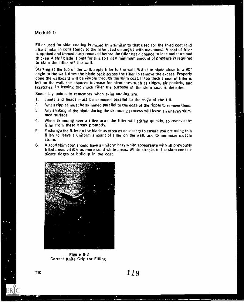
Module 5
Filler used for skim coating is mixed thin similar to that used for the third coat (andalso similar in consistency to the filler used on angles with machines). A coat of filleris applied and immediately removed before the filler has a chance to lose moisture andthicken. A stiff blade is best for this so that a minimum amount of pressure is requiredto skim the filler off the wall.
Starting at the top of the wall, apply filler to the wall. With the blade close to a 90°angle to the wall, draw the blade back across the filler to remove the excess. Properlydone the wallboard will be visible through the skim coat. If too thick a coat of filler isleft on the wall, the chances increase for blemishes such as ridges, air pockets, andscratches. In leaving too much filler the purpose of the skim coat is defeated.
Some key points to remember when skim coating are:1. Joints and beads must be skimmed parallel to the edge of the fill.2 Small ripples must be skimmed parallel to the edge of the ripple to remove them.3 Any shaking of the blade during the skimming process will leave an uneven skim-
med surface.4. When skimming over a filled area, the filler will stiffen quickly, so remove the
filler from these areas promptly.5. Exchange the filler on the blade as often as necessary to ensure you are using thin
filler, to leave a uniform amount of filler on the wall, and to minimize musclestrain.
6. A good skim coat should have a uniform hazy white appearance with all previouslyfilled areas visible as more solid white areas. White streaks in the skim coat in-dicate ridges or buildup in the coat.
Figure 5-3Correct Knife Grip for Filling
110 119
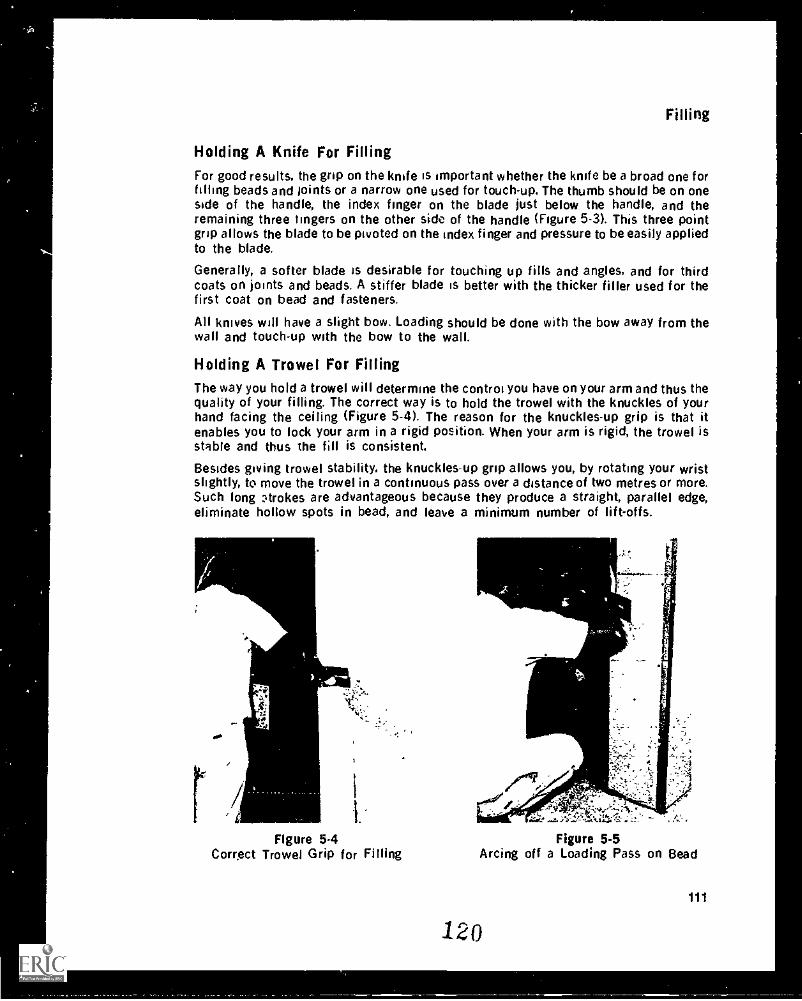
Filling
Holding A Knife For FillingFor good results. the grip on the knife is important whether the knife be a broad one forfilling beads and joints or a narrow one used for touch-up. The thumb should be on oneside of the handle, the index finger on the blade just below the handle, and theremaining three fingers on the other side of the handle (Figure 5-3). This three pointgrip allows the blade to be pivoted on the index finger and pressure to be easily appliedto the blade.
Generally, a softer blade is desirable for touching up fills and angles, and for thirdcoats on joints and beads. A stiffer blade is better with the thicker filler used for thefirst coat on bead and fasteners.
All knives will have a slight bow. Loading should be done with the bow away from thewall and touch-up with the bow to the wall.
Holding A Trowel For FillingThe way you hold a trowel will determine the control you have on your arm and thus thequality of your filling. The correct way is to hold the trowel with the knuckles of yourhand facing the ceiling (Figure 5-4). The reason for the knuckles-up grip is that itenables you to lock your arm in a rigid position. When your arm is rigid, the trowel isstable and thus the fill is consistent.
Besides giving trowel stability, the knuckles-up grip allows you, by rotating your wristslightly, to move the trowel in a continuous pass over a distance of two metres or more.Such long nrokes are advantageous because they produce a straight, parallel edge,eliminate hollow spots in bead, and leave a minimum number of lift-offs.
r
4.
/ 1
1.
Figure 5.4 Figure 5-5Correct Trowel Grip for Filling Arcing off a Loading Pass on Bead
120
111
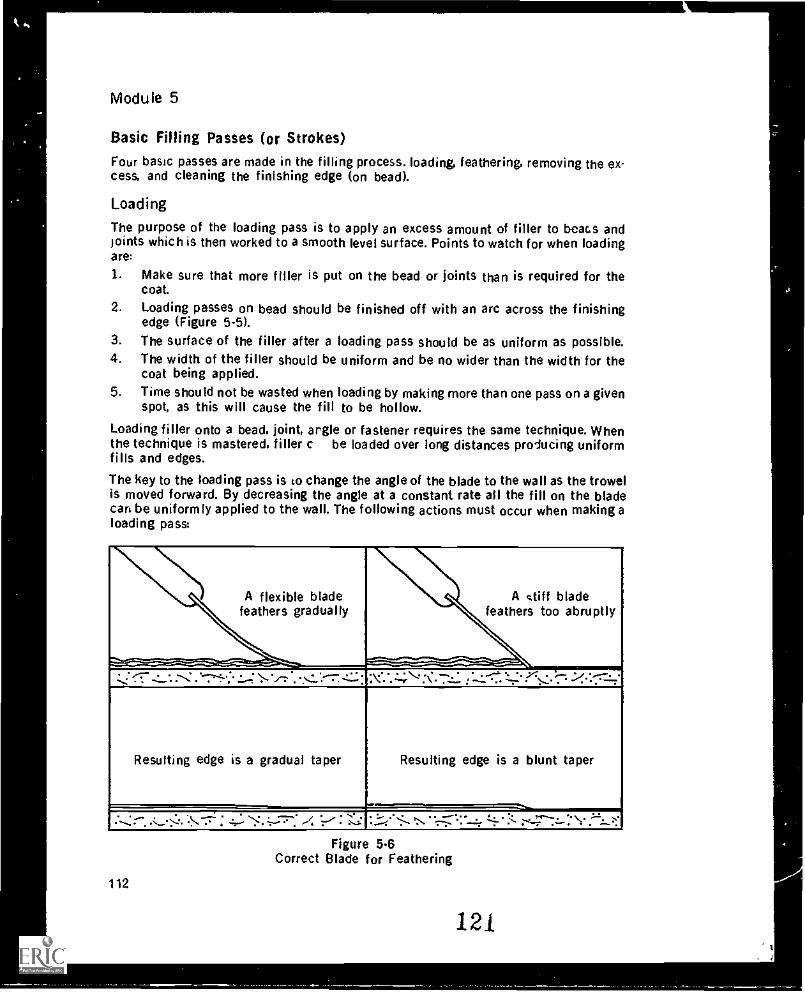
Module 5
Basic Filling Passes (or Strokes)Four basic passes are made in the filling process. loading. feathering, removing the ex-cess, and cleaning the finishing edge (on bead).
Loading
The purpose of the loading pass is to apply an excess amount of filler to beacs andjoints which is then worked to a smooth level surface. Points to watch for when loadingare
1. Make sure that more filler is put on the bead or joints than is required for thecoat.
2. Loading passes on bead should be finished off with an arc across the finishingedge (Figure 5-5).
3. The surface of the filler after a loading pass should be as uniform as possible.4. The width of the filler should be uniform and be no wider than the width for the
coat being applied.5. Time should not be wasted when loading by making more than one pass on a given
spot, as this will cause the fill to be hollow.
Loading filler onto a bead. joint, argle or fastener requires the same technique. Whenthe technique is mastered, filler c be loaded over long distances producing uniformfills and edges.
The key to the loading pass is co change the angle of the blade to the wall as the trowelis moved forward. By decreasing the angle at a constant rate all the fill on the bladecan be uniformly applied to the wall. The following actions must occur when making aloading pass:
A flexible bladefeathers gradually
A stiff bladefeathers too abruptly
----------------------.7-- ----,
.:_:' -:_"..--: ."-7-i-... ..," -",-:.......::.---7.:."..".: "N".".:-", :. 7. ; -z-::: :-::" ';.:.-.--....!.:'::::-:"
Resulting edge is a gradual taper Resulting edge is a blunt taper
: --..:__.>:. .. :. "7r ".2"..-:".':-.-- . -r:-.--.1"..::- :-4--.77-1-.
Figure 5.6Correct Blade for Feathering
112
121
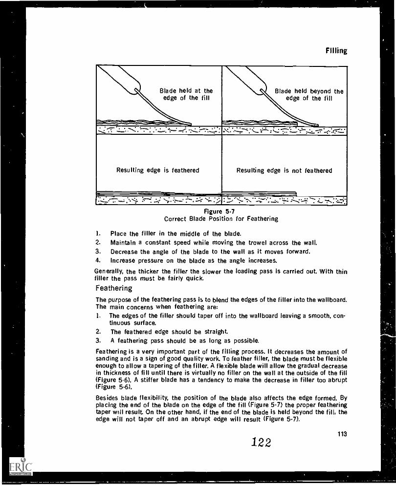
Filling
Blade held atedge of the fill
the Blade held beyond theedge of the fill
--.......* -7 .z__".7:..-:-* . -:-. 4.--* -:'...."...r-:-...:..*::: ...--..-='`." ":::": 11-:-."--7.--::(7--::
Resulting edge is feathered Resulting edge is not feathered
....:_.--7--..: <i. .::-: .:.-; >"-- ":--" ::-. ::( `;.- : : ..-.:".-- . "--4."*"."..z.. .7.. ': "" -.-...zzv;
Figure 5-7Correct Blade Position for Feathering
1. Place the filler in the middle of the blade.2. Maintain a constant speed while moving the trowel across the wall.3. Decrease the angle of the blade to the wall as it moves forward.4. Increase pressure on the blade as the angle increases.
Generally, the thicker the filler the slower the loading pass is carried out. With thinfiller the pass must be fairly quick.Feathering
The purpose of the feathering pass is to blend the edges of the filler into the wallboard.The main concerns when feathering are:1. The edges of the filler should taper off into the wallboard leaving a smooth, con-
tinuous surface.2. The feathered edge should be straight.3. A feathering pass should be as long as possible.
Feathering is a very important part of the filling process. It decreases the amount ofsanding and is a sign of good quality work. To feather filler, the blade must be flexibleenough to allow a tapering of the filler. A flexible blade will allow the gradual decreasein thickness of fill until there is virtually no filler on the wall at the outside of the fill(Figure 5-6). A stiffer blade has a tendency to make the decrease in filler too abrupt(Figure 5.6).
Besides blade flexibility, the position of the blade also affects the edge formed. Byplacing the end of the blade on the edge of the fill (Figure 5.7) the proper featheringtaper will result. On the other hand, if the end of the blade is held beyond the fill, theedge will not taper off and an abrupt edge will result (Figure 5 -7).
113
122
a
Module 5
Other factors affecting feathering are the filler formulation, the face paper of thewallboard, and the thickness of the filler. A problem with the raw materials that for-mulate the filler may make it difficult to shear, resulting in a rough or grainy featherededge even when proper feathering technique is used. Such an edge can also resultwhen the wallboard face paper is not smooth. Thick filler is alsays harder to featherout because it does not spread as easily and it is harder to get the proper blade anglewith It for feathering. When confronted with these adverse conditions, finishers. have topay closer attention to feathering the edges.
Removing the Excess
The purpose of the removing the excess pass is, as its name implies, to remove the ex-cess filler applied on the loading pass and in SO doing flatten and distribute the filler toproduce a level surface. The main concerns when making this pass are:1. The surface of the filler should be left smooth.2. For bead:
a. The bead should be full.b. Prior to making the pass, short strokes are made at the bottom of the bead to
eliminate a "baseboard" of filler.3. Joints in the filler should have a very srr 'ft-off.4. Ridges or lines should not be left in the filler.5, The pass should be as long as possible.
The number of passes to remove the excess is critical. It is possible to reduce the num-ber of passes by improving your technique and skill. Making more passes removes toomuch filler and invariably leaves the fill hollow.
Joining Wet FillerDuring any coat of filler you will have to join a fill to wet filler. When making the join,the object is to leave the least amount of lift-off as possible. Move the trowel 15 to 30cm beyond the join. As the trowel passes over the join, begin a combination ofmovements:
1. Gradually release pressure on the trowel until it is lifted from the wall.2. In a sweeping motion, revolve your wrist to bring the blade perpendicular to the
line of fill at the point where it is lifted from the filler.
Rough SandingAlways wear a mask when sanding. Be safe: wear only a mask that has been purchasedat a safety-supply store, since it will be one that has been approved for adequateprotection,
The intent of rough sanding is to remove lumps or ridges from previous fills on joints,angles and beads. Fasteners should never be rough sanded. The better the finisher, theless rough sanding is required. Rough sanding is not often necessary for the skilledtradesman. At most, rough sanding should be d light brushing or scraping; it should notbe a method of correcting poor filling techniques. Rough sanding can be done by:1. Using 80 grit sandpaper on a pole sander.2. Scraping the surface with a blade.
114
123
Filling
Rough sanding when properly done, should:1. Be done quickly.2. Remove edges, ridges and lumps.3. Clean the finishing edges of bead.4. Not buff the face paper of the wallboard.
Depending on the quality of the taping job or the coat of fill, bead, ;colts ana .nglesmay need rough sanding after taping and between succe..sive coats of filler.
When rough sanding bead, place the sander horizontally on n :- ail One pass up andone down will remove excess filler on the edges. Ridges left where filler was joinedmust also be removed; if not they may show through the finished job because the nextcoats of filler shrink around the ridges and accentuate them. Removing ridges isespecially important when a combination of taping and topping filler is used. If norough sanding is done to remove ridges in the taping filler, when the job is finish sand-ed the softer topping filler will be removed from around the ridge in the harder tapingfiller, leaving a ridge in the finished product. One pass up and one down with the headof the sander perpendicular to the edge of the bead, with special attention to ridgesand edges, should be sufficient. To remove big ridges sand them with the head of thesander moving parallel to the ridge.
When rough sanding joints between coats, apply greater pressure to the centre of thejoint than on the edges. Do not sand the filler d. Nn to the tape. One pass down the mid-dle of flats and butts with the head of the sander perpendicular to the joint, payingspecial attention to the edges, is sufficient. Angles need four passes to clean them off.one up and one down each side. Take care not to tear the tape or the surface of theboard. Fasteners should not have to be sanded between coats, but if the edge aroundthe fastener is not properly feathered it may be necessary to lightly sand the spot toremove the edge. In general, however, fasteners are not rough sanded as the papercould be torn and show through the final decoration.
Filling Vertical BeadA medium-stiff blade is desirable for filling bead so that less pressure will be needed toremove the excess filler. The filler is mixed relatively thick for bead. The stiffer theblade the less chance there is of removing too much filler and leaving the bead hollow.To leave the filler level use a slightly convex curved trowel to compensate for thepressure applied on the trowel.
Most vertical bead will have to be done in two sections: the bottoms or the part of thebead that can be comfortably reached from the floor; and the tops, the part thatrequires stilts or a scaffold to reach. Note that the top of a vertical bead must be filledwhile the bottom is still wet, otherwise uneven shrinkage and a crack will occur wherethe filler joins. When tying tops in with bottoms aiways keep a small amount of filler onthe blade to avoid pulling the partly dry filler.
First Coat (5 Passes) on Vertical BeadBefore the first coat and between successive coats, remove any bumps, ridges, or otherirregularities either by scraping with 3 blade or by rough sanding.1. Start loading at the top of the bead or as high as you can comfortably reach. Pull
115
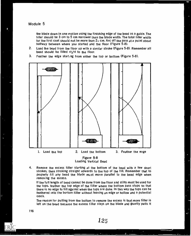
Module 5
the blade down in one motion using the finishing edge of the bead as a guide. Thefiller should be 3 cm to 5 cm narrower than the blade width. The total filler widthfor the first coat should not be more than cm. Arc off the pass at a point abouthalfway between where you started and the floor (Figure 5-8).
2. Load the bead from the floor up with a similar stroke (Figure 5-8). Remember allbead should be filled riVtt to the floor.
3. Feather the edge starting from either the top or bottom (Figure 5-8).
-411/111k-
1. Load the top 2. Load the bottom 3. Feather the euge
Figure 5.8Loading Vertical Bead
4. Remove the excess filler starting at the bottom of the bead with a few shortstrokes, then stroking straight upwards to the top of the fill. Remember that toproperly fill any bead the blade must move parallel to the bead edge whenremoving the excess.If the full length of bead cannot be done from the floor and stilts must be used forthe tops, feather the top edge of the filler where the bottom pass stops so thatthere is no edge to fill against when the tops are done. In this way the tops can befeathered into the bottom filler without leaving an edge or hollow and a potentialcrack.
The reason for pulling from the bottom to remove the excess is that more filler isleft on the bead because the excess filler stays on the blade and gravity pulls it
116
125
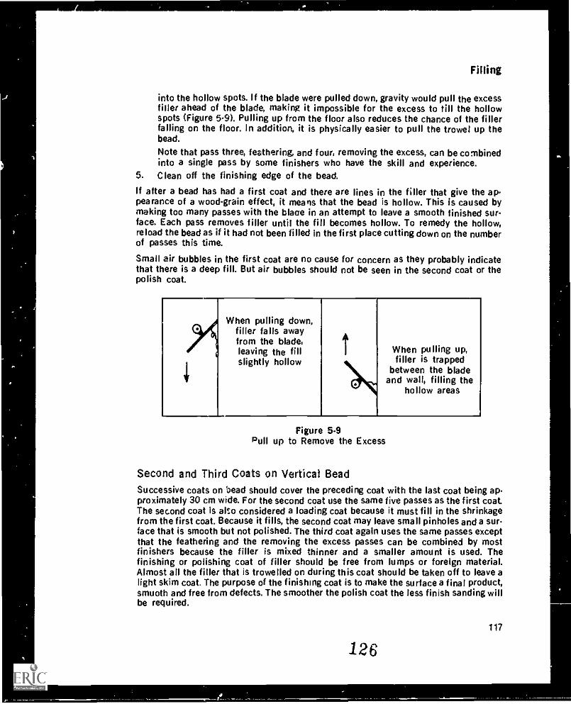
Filling
into the hollow spots. If the blade were pulled down, gravity would pull the excessfiller ahead of the blade, making it impossible for the excess to till the hollowspots (Figure 5.9). Pulling up from the floor also reduces the chance of the fillerfalling on the floor. In addition, it is physically easier to pull the trowel up thebead.
Note that pass three, feathering, and four, removing the excess, can be combinedinto a single pass by some finishers who have the skill and experience.
5. Clean off the finishing edge of the bead.
If after a bead has had a first coat and there are lines in the filler that give the ap-pearance of a wood-grain effect, it means that the bead is hollow. This is caused bymaking too many passes with the blaae in an attempt to leave a smooth finished sur-face. Each pass removes filler until the fill becomes hollow. To remedy the hollow,reload the bead as if it had not been filled in the first place cutting down on the numberof passes this time.
Small air bubbles in the first coat are no cause for concern as they probably indicatethat there is a deep fill. But air bubbles should not be seen in the second coat or thepolish coat.
0When pulling down,
filler falls awayfrom the blade,leaving the fillslightly hollow
0
When pulling up,filler is trapped
between the bladeand wall, filling the
hollow areas
Figure 5-9Pull up to Remove the Excess
Second and Third Coats on Vertical BeadSuccessive coats on bead should cover the preceding coat with the last coat being ap-proximately 30 cm wide. For the second coat use the same five passes as the first coat.The second coat is also considered a loading coat because it must fill in the shrinkagefrom the first coat. Because it fills, the second coat may leave small pinholes and a surface that is smooth but not polished. The third coat again uses the same passes exceptthat the feathering and the removing the excess passes can be combined by mostfinishers because the filler is mixed thinner and a smaller amount is used. Thefinishing or polishing coat of filler should be free from lumps or foreign material.Almost all the filler that is trowelled on during this coat should be taken off to leave alight skim coat. The purpose of the finishing coat is to make the surface a final product,smooth and free from defects. The smoother the polish coat the less finish sanding willbe required.
126117
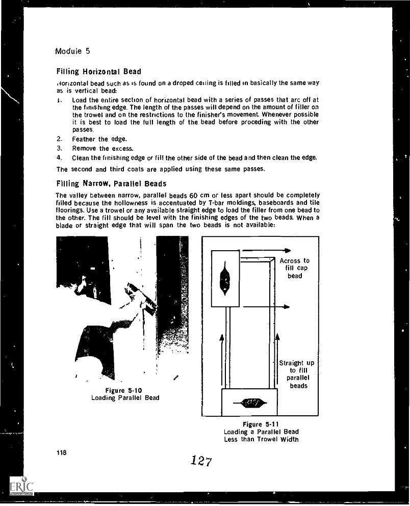
Modu le 5
Filling Horizontal Bead.lorizontal bead such as is found on a droped ceiling is filled in basically the same wayas is vertical bead:1. Load the entire section of horizontal bead with a series of passes that arc off at
the finishing edge. The length of the passes will depend on the amount of filler onthe trowel and on the restrictions to the finishers movement. Whenever possibleit is best to load the full length of the bead before preceding with the otherpasses.
2. Feather the edge.3. Remove the excess.4. Clean the finishing edge or fill the other side of the bead and then clean the edge.
The second and third coats are applied using these same passes.
Fining Narrow, Parallel BeadsThe valley between narrow, parallel beads 60 cm or less apart should be completelyfilled because the hollowness is accentuated by T-bar moldings, baseboards and tilefloorings. Use a trowel or any available straight edge to load the filler from one bead tothe other. The fill should be level with the finishing edges of the two beads. When ablade or straight edge that will span the two beads is not available:
118
Figure 5-10Loading Parallel Bead
---4,', Across to
fill capbead
Straight upto fill
parallelbeads
127
Figure 5-11Loading a Parallel BeadLess than Trowel Width
4
?
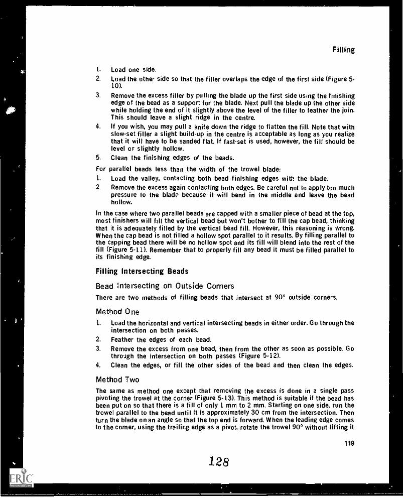
i
N
Filling
1. Load one side.2. Load the other side so that the filler overlaps the edge of the first side (Figure 5-
10).
3. Remove the excess filler by pulling the blade up the first side using the finishingedge of the bead as a support for the blade. Next pull the blade up the other sidewhile holding the end of it slightly above the level of the filler to feather the join.This should leave a slight ridge in the centre.
4. If you wish, you may pull a knife down the ridge to flatten the fill. Note that withslow-set filler a slight build-up in the centre is acceptable as long as you realizethat it will have to be sanded flat. If fast-set is used, however, the fill should belevel or slightly hollow.
5. Clean the finishing edges of the beads.
For parallel beads less than the width of the trowel blade:1. Load the valley, contacting both bead finishing edges with the blade.2. Remove the excess again contacting both edges. Be careful not to apply too much
pressure to the blade because it will bend in the middle and leave the beadhollow.
in the case where two parallel beads are capped with a smaller piece of bead at the top,most finishers will fill the vertical bead but won't bother to fill the cap bead, thinkingthat it is adequately filled by the vertical bead fill. However, this reasoning is wrong.When the cap bead is not filled a hollow spot parallel to it results. By filling parallel tothe capping bead there will be no hollow spot and its fill will blend into the rest of thefill (Figure 5-11). Remember that to properly fill any bead it must be filled parallel toits finishing edge.
Filling Intersecting Beads
Bead intersecting on Outside CornersThere are two methods of filling beads that intersect at 90° outside corners.
Method One1. Load the horizontal and vertical intersecting beads in either order. Go through the
intersection on both passes.2. Feather the edges of each bead.3. Remove the excess from one bead, then from the other as soon as possible. Go
through the intersection on both passes (Figure 5-12).4. Clean the edges, or fill the other sides of the bead and then clean the edges.
Method TwoThe same as method one except that removing the excess is done in a single passpivoting the trowel at the corner (Figure 5-13). This method is suitable if the bead hasbeen put on so that there is a fill of only 1 mm to 2 mm. Starting on one side, run thetrowel parallel to the bead until it is approximately 30 cm from the intersection. Thenturn the blade on an angle so that the top end is forward. When the leading edge comesto the corner, using the trailing edge as a pivot, rotate the trowel 90° without lifting it
128
119
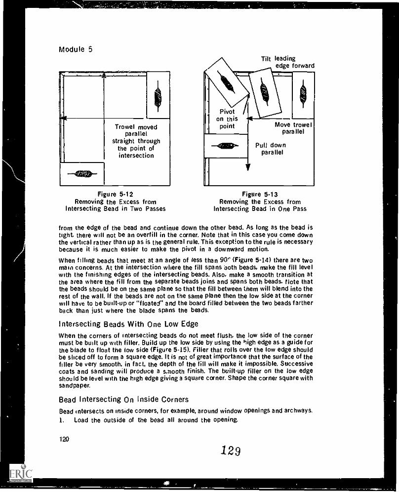
Module 5
Trowel movedparallel
straight throughthe point ofintersection
Figure 5-12Removing the Excess from
Intersecting Bead in Two Passes
Tilt leadingedge forward
Move trowelparallel
Pull downparallel
Figure 5-13Removing the Excess from
Intersecting Bead in One Pass
from the edge of the bead and continue down the other bead. As long as the bead istight. there will not be an overfill in the corner. Note that in this case you come downthe vertical rather than up as is the general rule. This exception to the rule is necessarybecause it is much easier to make the pivot in a downward motion.
When filling beads that meet at an angle of less than 90' (Figure 5-14) there are twomain concerns. At the intersection where the fill spans both beads, make the fill levelwith the finishing edges of the intersecting beads. Also, make a smooth transition atthe area where the fill from the separate beads joins and spans both beads. Note thatthe beads should be on the same plane so that the fill between them will blend into therest of the wall. If the beads are not on the same plane then the low side at the cornerwill have to be built-up or "floated" and the board filled between the two beads fartherback than just where the blade spans the beads.
Intersecting Beads With One Low EdgeWhen the corners of intersecting beads do not meet flush, the low side of the cornermust be built up with filler. Build up the low side by using the high edge as a guide forthe blade to float the low side (Figure 5-15). Filler that rolls over the low edge shouldbe sliced off to form a square edge. It is not of great importance that the surface of thefiller be very smooth, in fact, the depth of the fill will make it impossible. Successivecoats and sanding will produce a smooth finish. The built-up filler on the low edgeshould be level with the high edge giving a square corner. Shape the corner square withsa ndpa per.
Bead Intersecting On Inside CornersBead intersects on inside corners, for example, around window openings and archways.
1. Load the outside of the bead all around the opening.
120
129
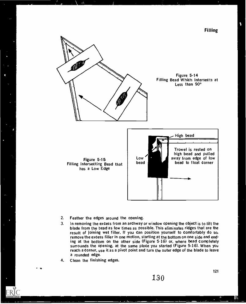
IS
Figure 5.15Filling Intersecting Bead that
has a Low Edge
Filling
Figure 5.14Filling Bead Which Intersects at
Less than 90°
High bead
Trowel is rested onhigh bead and pulled
Low away from edge of lowbead bead to float corner
2. Feather the edges around the opening.3. In removing the excess from an archway or window opening the object is to lift the
blade from the bead as few times as possible. This eliminates ridges that are theresult of joining wet filler. If you can position yourself to comfortably do so,remove the excess filler in one motion, starting at the bottom on one side and endsing at the bottom on the other side (Figure 5-16) or, where bead completelysurrounds the opening, at the same place you started (Figure 5.16). When youreach a corner, use it as a pivot point and turn the outer edge of the blade to leavea rounded edge,
4. Clean the finishing edges.
130121
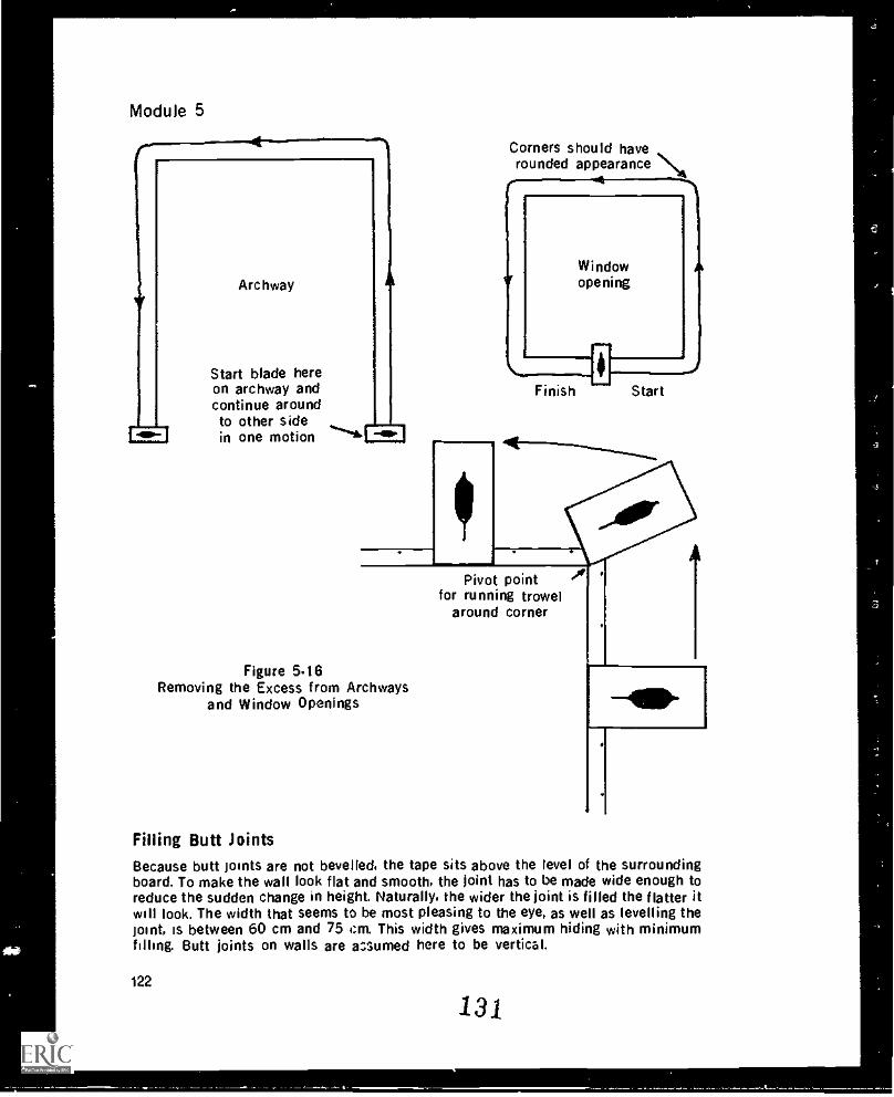
Module 5
Archway
Start blade hereon archway andcontinue aroundto other sidein one motion
.y
Figure 5.16Removing the Excess from Archways
and Window Openings
Corners should haverounded appearance
Finish Start
Pivot pointfor running trowel
around corner
Filling Butt JointsBecause butt joints are not bevelled, the tape sits above the level of the surroundingboard. To make the wall look flat and smooth, the joint has to be made wide enough toreduce the sudden change in height. Naturally, the wider the joint is filled the flatter itwill look. The width that seems to be most pleasing to the eye, as well as levelling thejoint, is between 60 cm and 75 i:m. This width gives maximum hiding with minimumfilling. Butt joints on walls are azumed here to be vertical.
122
131
A
a
Filling
First Coat on Butt JointsBefore the first coat and between successive coats, remove bumps, ridges, or otherirregularities either by scraping with a blade or by rough sanding.
The first coat on a butt joint should be one blade width (25 cm) centred on the tape.Four passes are necessary:1. Make one loading pass up the centre of the tape.2. Feather the edge on one side.3. Feather the edge on the other side.4. Another pass up the centre to remove the excess and flatten the fill.
The last pass may leave two thin lines, one on either side of the centre. The higher thetape the more filler is required to load it and thus the more prominent are the lines.These lines are acceptable as they can be reference points for the second coat. Thefirst coat on the joint should fill the tape with just enough mud to cover it. The tapeshould be visible, but should not appear dry. This is the highest the joint will be as thetape is coverers by only one more skim coat to polish it.
Second Coat on ButtsRough sand between coats.
The second coat on butt joints requires four passes on each side of the joint for a totalof eight passes. This coat should be about 60 cm wide. On each side of the butt joint:1. Following the edge of the tape or the line left by the final pass on the first coat,
make a loading pass up the joint2. Feather one edge of the fill.3. Feather the other edge.4. Make another pass up the centre to remove the excess and flatten the fill.
Note that the second coat on either side does not touch the tape.
Third Coat on ButtsIf the tape is tight to the wallboard to start with, two coats will do a good job. However,a third or polish coat is often required. The polish coat is done with thin filler and alonger blade. The entire surface of the butt is covered and then skimmed off. Afterpolish coating, the joint will be 60 to 75 cm wide and will be ready for sanding.
Note that if it is necessary to load any filler on the third coat, it means .hat the firstand second coats have not been properly applied.
Filling Butt Joints on Curved SurfacesButt joints on flat surfaces are not easy to fill, but on curved surfaces they are evenmore difficult. it is most critical that the tape be wiped tightly to the board: the closerthe tape is to the board, the less problems you will haye. Filled joints on curved sur-faces must maintain the curvature of the wall; they should not be flat.
132123
Module 5
First Coat on Butts on Convex SurfacesUsing a flexible knife that will bend to the curve of the wall:1. Make a loading pass down the centre of the butt tape.2. Feather the edges.3 Remove the excess with a final pass down the centre of the tape. The tape should
be visible through the filler. The filler should not flatten out at any section alongthe curve, but should always follow the curve.
Second Coat
1 Make a loading pass on each side of the tape. No filler should be put on the tapeduring the second coat.
2. Feather the edges.3. Remove the excess.
Third Coat1. Check the joint for flat spots by running your hand over the joint, or by using a
light or a straight edge. If you find any flat spots, sand them out or refill them tomatch the curve before applying the final coat.
2. Load the entire filled area.3. Remove most of the filler leaving only a skim coat on the surface. The width of the
joint should probably be wider than a butt joint on a flat surface. This extra widthhelps hide the joint and maintain the curve of the wall.
First Coat on Butts on Concave SurfacesTo properly fill butt joints on a concave surface the tape must be covered. As with con-vex surfaces, use a wide flexible blade that will bend to the curve of the surface.1. Make a loading pass over the tape.2. Feather ths edges.3. Remove the excess filler. The tape should be covered to maintain the curve of the
surface. Do not try to get the filler perfectly smooth.
Second Coat1. Load filler over the joint overlapping the first coat by 2 to 5 cm on each side.2. Feather the edges.3. Remove the excess maintaining the curve.
Third Coat1. Load filler over the joint.2. Remove the excess leaving only a skim coat.
A concave butt joint finished in this manner may be only 25 to 30 cm wide, but this isnot a problem. The major concern is that the filled joint maintain the curve.
124
133
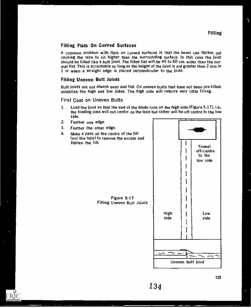
Filling
Filling Flats On Curved SurfacesA common problem with flats on curved surfaces is that the bevel can flatten outcausing the tape to sit higher than the surrounding surface. In this case the jointshould be filled like a butt joint. The filled flat will be 45 to 60 cm, wider than the nor-mal flat. This is acceptable as long as the height of the joint is not greater than 2 mm in1 m when a straight edge is placed perpendicular to the joint.
Filling Uneven Butt JointsButt joints are not always even and flat. On uneven butts that have not been pre-filled,establish the high and low sides. The high side will require very little filling.
First Coat on Uneven Butts1. Load the joint so that the end of the blade runs on the high side (Figure 5-17), i.e.,
the loading pass will not centre on the tape but rather will be off-centre to the lowside.
2. Feather one edge.
3. Feather the other edge.4. Make a pass up the centre of the fill
(not the tape) to remove the excess andflatten the fill.
Figure 5.17Filling Uneven Butt Joints
Highside
Troweloff-centreto the
low side
Lowside
Uneven butt joint
134125
\
Module 5
What the first coat on an uneven butt joint does is to move the centre of the fill for thejoint to the low side. The high side only requires a small amount of filler to skim thetape so that it is covered adequately for decorating. if too much filler is left on the highside, the joint will be covered but will still be uneven.
Second and Third Coats On Uneven ButtsThe second coat for uneven butts is basically the same as that for even butts. Using thelines left by the last pass on the first coat four passes are made on either side of thecentre of the fill (not the centre of the tape). Note, however, ..tat unlike with even butts,the second coat on uneven butts skims the tape because the tape is off-centre inrelation to the fill.
The third or final coat will skim in the full width of the joint. Most of the filling will beon the low side so it may be necessary for the joint to be wider than 70 cm. For thejoint to be acceptable, a 1250 mm straight edge, when place on the joint, should nothave more than a 2 mm gap on either side.
Filling Flats
First Coat on FlatsBefore the first coat and between successive coats, remove bumps, ridges. or otherirregularities either by scraping with a blade or by rough sanding.
The tape on flats should be below the surface of the surrounding board. Bumps in thetape should be cut out because likely there is a broken piece of board or some othermaterial behind the bump. It is easier to remove bumps than to fill around them.
Flats here are assumed to be horizontal. Always fill flats right to the angle, and as closeas possible to the finishing edge of the bead. This covers the area where the filler mayshrink back because of the bevel in the board. Also, fill right over butt joints even if thefilled butt joint covers the flat.
The first coat should be no wider than 25 cm. Filler should be applied in long strokesas far along the flat as possible; long strokes produce the best effect and also get thejob done quicker. The angle of the blade should be approximately 45 degrees so that aminimum amount of filler is left.
While covering the tape, the first coat should be full and as free from defects aspossible. Defects such as air pockets and scratches must be avoided as they are belowthe surface of the filler and cannot be sanded out. On the other hand, lumps and ridgescan be sanded out if the sander conscientiously watches for them. However, leave asfew defects as possible in order to make the joint continuous.
The passes made for the first .:oat on flats are:1. Load the flat down the middle of the joint so that it is about 3 mm thick and about
20 cm wide. Where drying conditions permit, load the entire length of the jointbefore feathering.
2. Feather one edge.3. Feather the other edge.4. Remove the excess with d pass down the centre of the flat. Small edges on either
side of the centre of the joint mean that too much filler has been left on the joint.
126
135
Filling
With powdered, slow-setting filler, it is desirable to leave a slight build-up (1-2mm) over the centre of the joint on this pass to compensate for shrinkage. A cur-ved blade can be used to get this build-up since more filler is left in the middle ofthe joint than on the edges. With pre-mix, you will have to check the shrinkagebefore knowing if it is necessary to leave the build-up. Some pre-mixes will needthe build-up but others won't.
If after a few minutes the full width of the tape can be seen in spots, it means thatuneven pressure has been applied to the blade thereby removing too much filler fromthe joint. The joint must be filled again, making sure the pressure on the blade is even.
When filling over any joint that has previously been filled, e.g., when filling flats overbutt joints, it is important to compensate for the drying of the filler. The wallboard willabsorb moisture from the previously applied filler causing the filler to have a differentconsistency from when first put on. As well, a film will start to form on the surface andcause the filler to tear or "pull" as the blade is passed over it. To avoid pulling, alwayshave filler on the blade to feather over the drying filler. If necessary, leave a small edgethat can be easily sanded off.
As the filler dries, if only half the width of the tape can be seen, it means that the edgesof the board are uneven. To remedy this defect, you must build up the low side (thecovered side) and make ,t wider so that the build-up will not be noticeable. Make thelast stroke with the blade down the centre of the fill (not the tape) to remove the excessfiller and leave a flat surface.
Second Coat On FlatsThe second coat on flats is a thin polish coat about 30 cm wide. The passes are thesame as for the first coat. Make cure that the loading pass is wider than that for thefirst coat. There is usually no third coat on flats, if tapes are wiped properly the bevel isfull making it only necessary to flatten and smooth the joint, a job that can be done intwo coats.
Filling Butts and Flats With MachinesThe advantage of using machines for filling is the speed with which joints and anglescan be filled. When the machines are set up and run properly only minor touch-up isrequired. Some finishers, however, insist on going over the joints with a knife or trowelto smooth the fill left by the boxes This is a poor practice because it defeats the timesaving advantage of the machine. If machine filled joints have to be completely goneover by hand, the machines are not being run properly.
Filling Machines (Boxes)Filling machines or boxes come in three sizes 18 cm, 25 cm, and 30 cm. The 30 cmbox is used only for finishing; the 18 cm and 25 cm boxes are used for loading coats.The boxes are metal with a hinged back to which a handle is attached (Figure 5 -18). Thehandle is used to apply pressure which causes filler to spread onto the wall. Theleading edge of the box has wheels on a pivoted axle enabling the box to run easily onthe wall. The wheels should be oiled at least 12 hours in advance of use so that the ex-cess oil will run off. If you oil the wheels just before the boxes are used, oil film may bedeposited on the board and cause the filler to peel off the wall.
136127
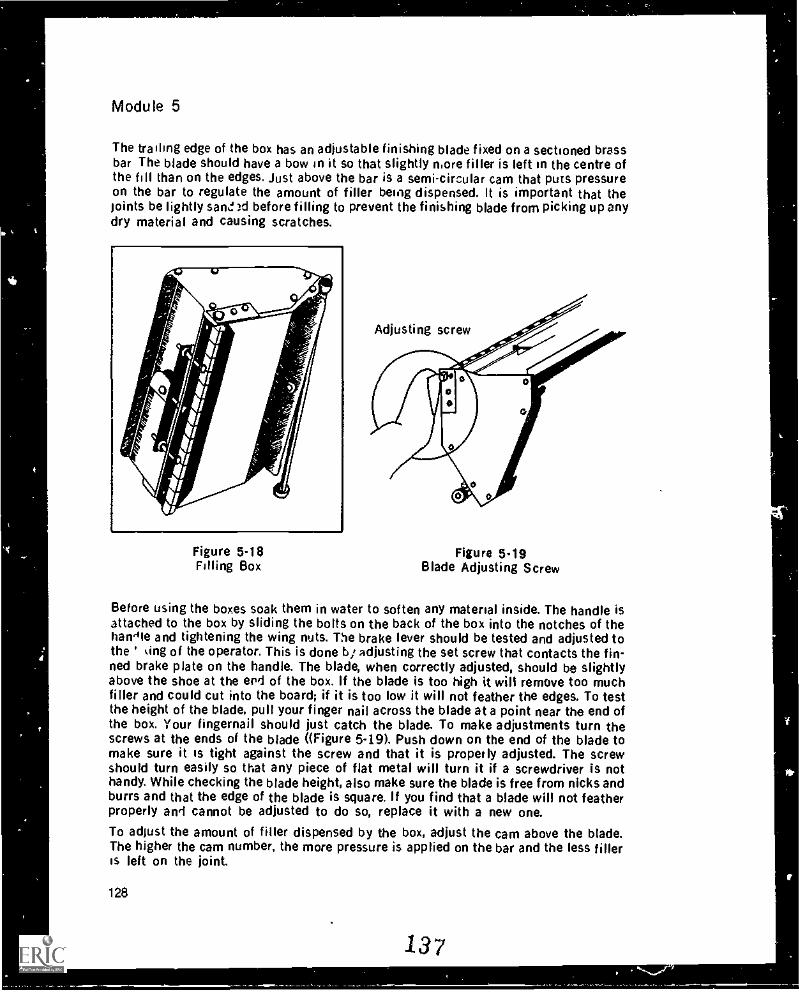
Module 5
The trailing edge of the box has an adjustable finishing blade fixed on a sectioned brassbar The blade should have a bow in it so that slightly more filler is left on the centre ofthe fill than on the edges. Just above the bar is a semi-circular cam that puts pressureon the bar to regulate the amount of filler being dispensed. It is important that thejoints be lightly sand )d before filling to prevent the finishing blade from picking up anydry material and causing scratches.
Figure 5-18Filling Box
Adjusting screw
Figure 5.19Blade Adjusting Screw
Before using the boxes soak them in water to soften any material inside. The handle isattached to the box by sliding the bolts on the back of the box into the notches of thehandle and tightening the wing nuts. The brake lever should be tested and adjusted tothe ' sing of the operator. This is done b; adjusting the set screw that contacts the fin-ned brake plate on the handle. The blade, when correctly adjusted, should be slightlyabove the shoe at the erld of the box. If the blade is too high it will remove too muchfiller and could cut into the board; if it is too low it will not feather the edges. To testthe height of the blade, pull your finger nail across the blade at a point near the end ofthe box. Your fingernail should just catch the blade. To make adjustments turn thescrews at the ends of the blade ((Figure 549). Push down on the end of the blade tomake sure it is tight against the screw and that it is properly adjusted. The screwshould turn easily so that any piece of flat metal will turn it if a screwdriver is nothandy. While checking the blade height, also make sure the blade is free from nicks andburrs and that the edge of the blade is square. If you find that a blade will not featherproperly and cannot be adjusted to do so, replace it with a new one.To adjust the amount of filler dispensed by the box, adjust the cam above the blade.The higher the cam number, the more pressure is applied on the bar and the less fillerIs left on the joint.
128
137
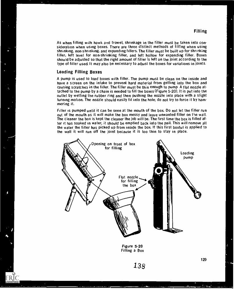
Filling
As when filling with hawk and trowel, shrinkage in the filler must be taken into con-sideration when using boxes. There are three distinct methods of filling when usingshrinking, non-shrinking, and expanding fillers. The filler must be built up for shrinkingfiller, left level for non-shrinking filler, and left hollow for expanding filler. Boxesshould be adjusted so that the right amount of filler is left on the joint according to thetype of filler used. It may also be necessary to adjust the boxes for variations in joints.
Loading Filling BoxesA pump is used to load boxes with filler. The pump must be clean on the inside andhave a screen on the intake to prevent hard material from getting into the box andcausing scratches in the filler. The filler must be thin enough to pump A flat nozzle at-tached to the pump by a chain is needed to fill the boxes (Figure 5-20). It is put into theoutlet by wetting the rubber ring and then pushing the nozzle into place with a slightturning motion. The nozzle should easily fit into the hole; do not try to force it by ham-mering it.
Filler as pumped until it can be seen at the mouth of the box. Do not let the filler runout of the mouth as it will make the box messy and leave unwanted filler on the wall.The cleaner the box is kept the cleaner the job will be. The first time the box is filled af-ter it has soaked in water, it should be emptied back into the pail. This will remove allthe water the filler has picked up from inside the box. If this first boxful is applied tothe wall it will run off the joint because it is too thin to stay in place.
Opening on front of boxfor filling
Loadingpump
Flat nozzlefor fillingthe box
Figure 5.20Filling a Box
138129
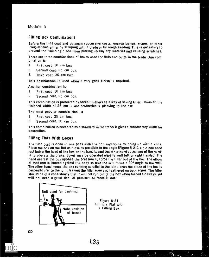
Module 5
Filling Box CombinationsBefore the first coat and between successive coats, remove bumps, ridges, or otherirregularities either by scraping with a blade or by rough sanding. This is necessary toprevent the finishing blade from picking up any dry material and causing scratches.
There are three combinations of boxes used for flats and butts in the trade. One com-bination is:1. First coat, 18 cm box.2. Second coat, 25 cm box.3. Third coat, 30 cm box.
This combination is used when a very good finish is required.
Another combination is:1. First coat, 18 cm box.2. Second coat, 25 cm box.
This combination is preferred by some finishers as a way of saving filler. However, thefinished width of 25 cm is not aesthetically pleasing to the eye.
The most popular combination is:1. First coat, 25 cm box.2. Second coat, 30 cm box.
This combination is accepted as a standard in the trade; it gives a satisfactory width fordecoration.
Filling Flats With BoxesThe first coat is done in one pass with the box, and some touching up with a knife.Place the box on the flat as close as possible to the angle (Figure 5-21). Hold one handjust below the head of the box on the handle, and the other hand at the end of the hand-le to operate the brake. Boxes may be operated equally well left or right handed. Thehand nearest the box applies the pressure to force the filler out of the box. The elbowof that arm is braced against the body so that the arm forms a 90° angle to the wall.The other hand keeps the box running parallel to the joint. Thus the blade of the box isperpendicular to the joint leaving the filler even and feathered on both edges. The fillershould be of a consistency that it will not run out of the box when turned sideways, yetwill not need a great deal of pressure to force it out.
130
Figure 5-21Filling a Flat with
a Filling Box
139
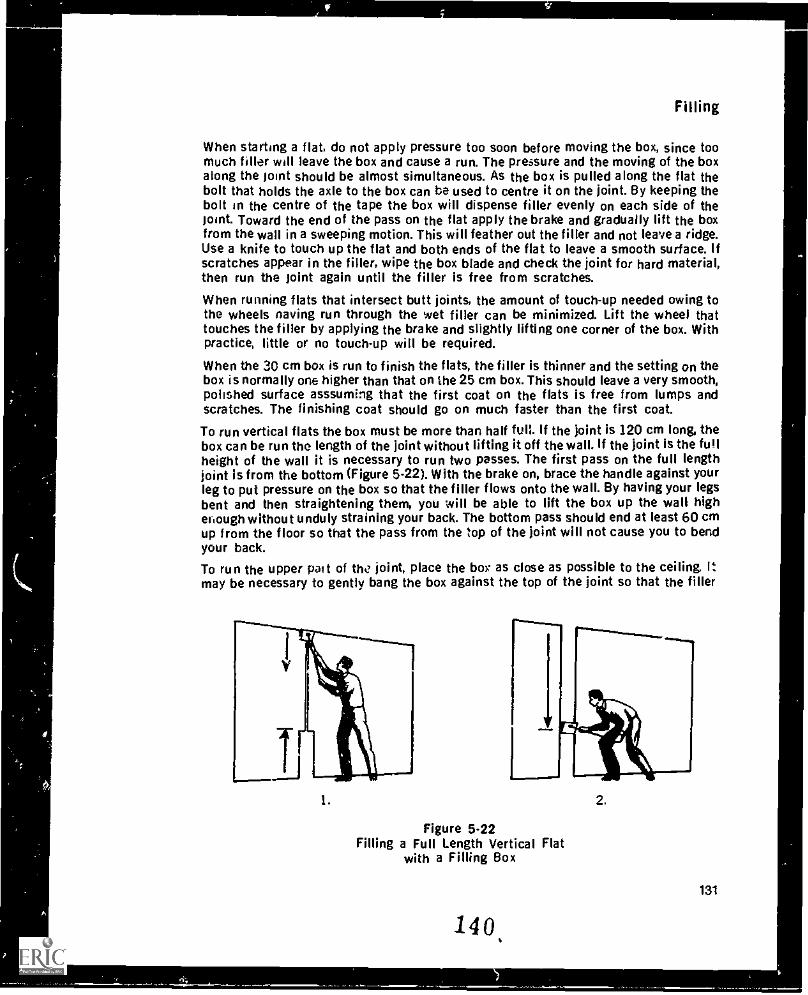
Filling
When starting a flat, do not apply pressure too soon before moving the box, since toomuch filler will leave the box and cause a run. The pressure and the moving of the boxalong the joint should be almost simultaneous. As the box is pulled along the flat thebolt that holds the axle to the box can be used to centre it on the joint. By keeping thebolt in the centre of the tape the box will dispense filler evenly on each side of thejoint. Toward the end of the pass on the flat apply the brake and gradually lift the boxfrom the wall in a sweeping motion. This will feather out the filler and not leave a ridge.Use a knife to touch up the flat and both ends of the flat to leave a smooth surface. Ifscratches appear in the filler, wipe the box blade and check the joint for hard material,then run the joint again until the filler is free from scratches.
When running flats that intersect butt joints, the amount of touch-up needed owing tothe wheels naving run through the wet filler can be minimized. Lift the wheel thattouches the filler by applying the brake and slightly lifting one corner of the box. Withpractice, little or no touch-up will be required.
When the 30 cm box is run to finish the flats, the filler is thinner and the setting on thebox is normally one higher than that on the 25 cm box. This should leave a very smooth,polished surface asssuming that the first coat on the flats is free from lumps andscratches. The finishing coat should go on much faster than the first coat.
To run vertical flats the box must be more than half full. If the joint is 120 cm long, thebox can be run the length of the joint without lifting it off the wall. If the joint is the fullheight of the wall it is necessary to run two passes. The first pass on the full lengthjoint is from the bottom (Figure 5-22). With the brake on, brace the handle against yourleg to put pressure on the box so that the filler flows onto the wall. By having your legsbent and then straightening them, you will be able to lift the box up the wall highefiough without unduly straining your back. The bottom pass should end at least 60 cmup from the floor so that the pass from the top of the joint will not cause you to bendyour back.
To run the upper pal t of the joint, place the box" as close as possible to the ceiling. Itmay be necessary to gently bang the box against the top of the joint so that the filler
1.
Figure 5-22Filling a Full Length Vertical Flat
with a Filling Box
140,
2.
131
Module 5
will be forced out. With the brake on. pull the box down the joint until pressure keepsthe wheels from lifting off the wall, then release the brake. The box will be ap-proximately 60 cm from the ceiling when the brake can be released.
Filling Butts With BoxesIf wall butt joints are fairly level, they can be run with a box, but if they are uneven theyshould be done by hand. The exception to this is butts on ceilings that are to be tex-tured. These are run level or not when boxes are used. There are three methods for run-ning butt joints by machine:
Method 1
Coat 11. With a 25 cm box run each side of the joint with the edge of the box on the centre
of the tape.2. While the filler is still wet, take a knife and skim in any exposed tape.
Coat 21. Same as coat 1 with a 30 cm box.
Method 2
Coat 1I. Run down the centre of the tape with an 18 cm or 25 cm box. The tape should be
just visible through the filler.
Coat 21. With a 25 cm box run each side of the tape (not over the tape).
Coat 31. Repeat coat 2 with a 30 cm box.
Method 3
This method is for ceilings or other surfaces that will be textured and where there isnot the concern for a perfectly smooth joint.
Coat 11. Run a 25 cm box down the centre of the tape.
Coat 21. Run a 30 cm box down both sides of the tape (not over the tape).
Filling Ceilings With BoxesWhen running the box on the ceiling, adjust the sliding grip on the handle so that thearm of the hand nearest the box is fully extended and braced against the grip (Figure 5-23). This arm acts as a fulcrum for applying pressure with the other arm. Put pressure
132
141
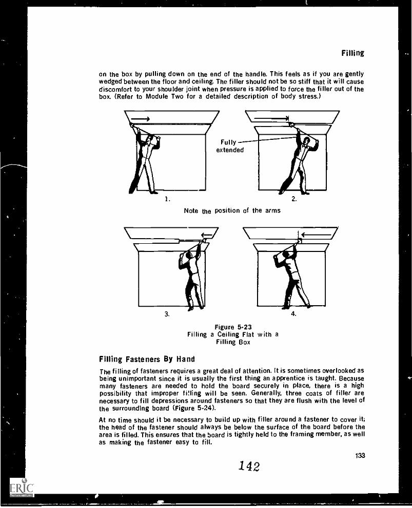
Filling
on the box by pulling down on the end of the handle. This feels as if you are gentlywedged between the floor and ceiling. The filler should not be so stiff that it will causediscomfort to your shoulder joint when pressure is applied to force the filler out of thebox. (Refer to Module Two for a detailed description of body stress.)
1.
Fullyextended
Note the position of the arms
Figure 5.23Filling a Ceiling Flat with a
Filling Box
Fining Fasteners By HandThe filling of fasteners requires a great deal of attention. It is sometimes overlooked asbeing unimportant since it is usually the first thing an apprentice is taught. Becausemany fasteners are needed to hold the board securely in place, there is a highpossibility that improper ',Ming will be seen. Generally, three coats of filler arenecessary to fill depressions around fasteners so that they are flush with the level ofthe surrounding board (Figure 5.24).
At no time should it be necessary to build up with filler around a fastener to cover it;the head of the fastener should always be below the surface of the board before thearea is filled. This ensures that the board is tightly held to the framing member, as wellas making the fastener easy to fill.
142133
__1111r_
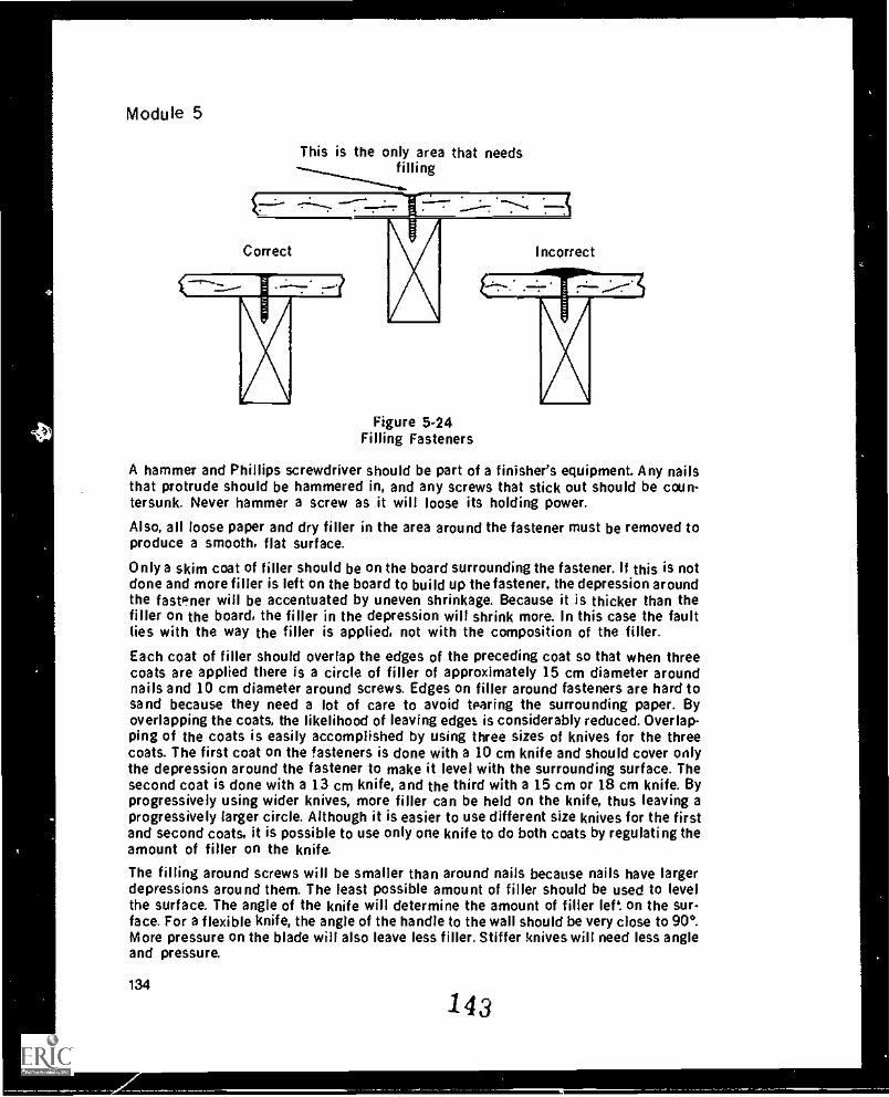
44
Module 5
This is the only area that needstiling
----- r''.----, - .....r. 7---c --
Correct Incorrect
Figure 5.24Filling Fasteners
A hammer and Phillips screwdriver should be part of a finisher's equipment. Any nailsthat protrude should be hammered in, and any screws that stick out should be coun-tersunk. Never hammer a screw as it will loose its holding power.
Also, all loose paper and dry filler in the area around the fastener must be removed toproduce a smooth, flat surface.
Only a skim coat of filler should be on the board surrounding the fastener. If this is notdone and more filler is left on the board to build up the fastener, the depression aroundthe fastener will be accentuated by uneven shrinkage. Because it is thicker than thefiller on the board, the filler in the depression will shrink more. In this case the faultlies with the way the filler is applied, not with the composition of the filler.
Each coat of filler should overlap the edges of the preceding coat so that when threecoats are applied there is a circle of filler of approximately 15 cm diameter aroundnails and 10 cm diameter around screws. Edges on filler around fasteners are hard tosand because they need a lot of care to avoid tearing the surrounding paper. Byoverlapping the coats, the likelihood of leaving edges is considerably reduced. Overlap-ping of the coats is easily accomplished by using three sizes of knives for the threecoats. The first coat on the fasteners is done with a 10 cm knife and should cover onlythe depression around the fastener to make it level with the surrounding surface. Thesecond coat is done with a 13 cm knife, and the third with a 15 cm or 18 cm knife. Byprogressively using wider knives, more filler can be held on the knife, thus leaving aprogressively larger circle. Although it is easier to use different size knives for the firstand second coats, it is possible to use only one knife to do both coats by regulating theamount of filler on the knife.
The filling around screws will be smaller than around nails because nails have largerdepressions around them. The least possible amount of filler should be used to levelthe surface. The angle of the knife will determine the amount of filler left on the sur-face. For a flexible knife, the angle of the handle to the wall should be very close to 90°.More pressure on the blade will also leave less filler. Stiffer knives will need less angleand pressure.
134
143
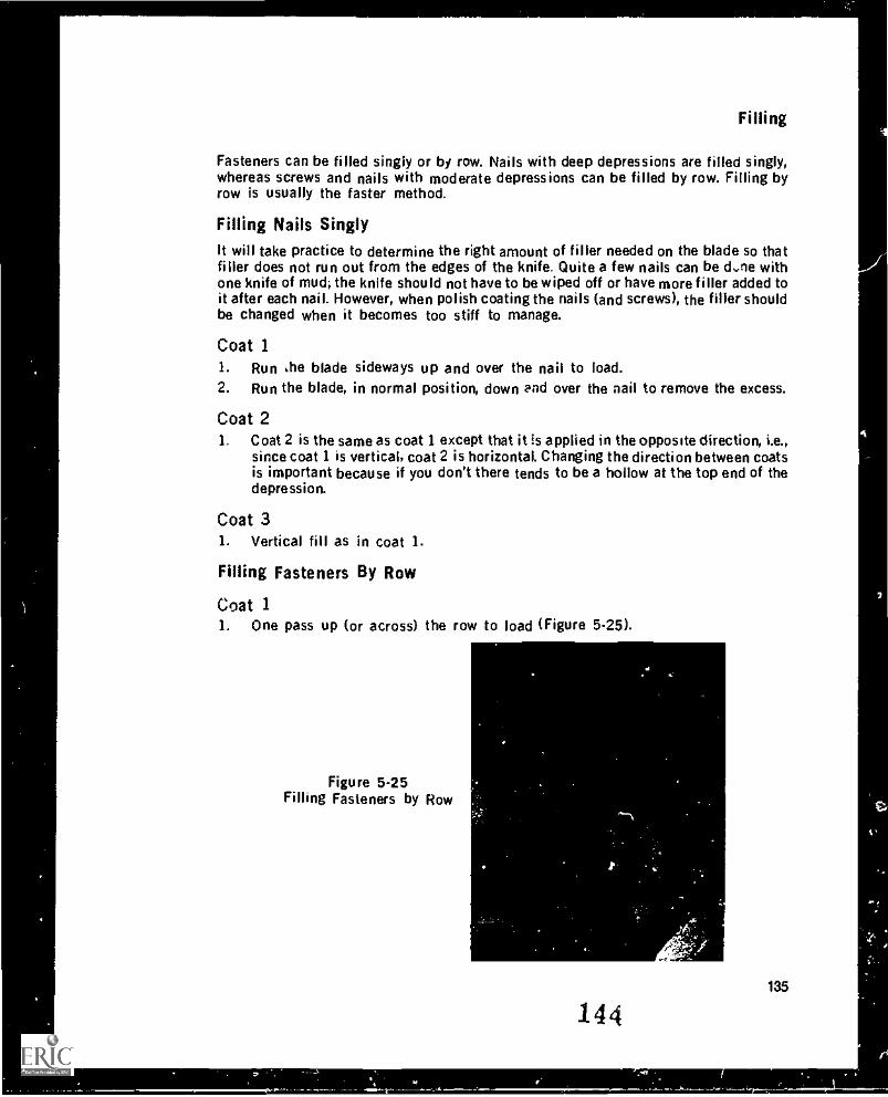
Filling
Fasteners can be tilled singly or by row. Nails with deep depressions are filled singly,whereas screws and nails with moderate depressions can be filled by row. Filling byrow is usually the faster method.
Filling Nails SinglyIt will take practice to determine the right amount of filler needed on the blade so thatfiller does not run out from the edges of the knife. Quite a few nails can be d...ne withone knife of mud; the knife should not have to be wiped off or have more filler added toit after each nail. However, when polish coating the nails (and screws), the filler shouldbe changed when it becomes too stiff to manage.
Coat 11. Run he blade sideways up and over the nail to load.2. Run the blade, in normal position, down and over the nail to remove the excess.
Coat 21. Coat 2 is the same as coat I except that it is applied in the opposite direction, i.e.,
since coat 1 is vertical, coat 2 is horizontal. Changing the direction between coatsis important because if you don't there tends to be a hollow at the top end of thedepression.
Coat 3L Vertical fill as in coat I.
Filling Fasteners By Row
Coat 1I. One pass up (or across) the row to load (Figure 5-25).
Figure 5-25Filling Fasteners by Row
144135
7
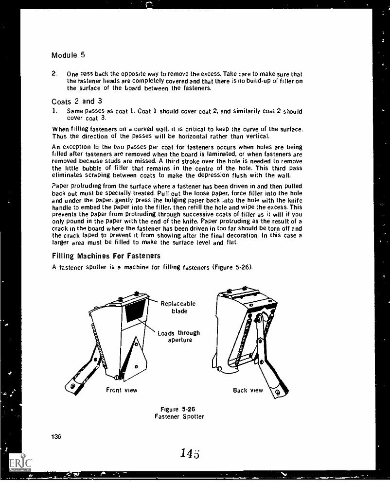
L
Module 5
2. One pass back the opposite way to remove the excess. Take care to make sure thatthe fastener heads are completely covered and that there is no build-up of filler onthe surface of the board between the fasteners.
Coats 2 and 31. Same passes as coat 1. Coat 1 should cover coat 2, and similarily coot 2 should
cover coat 3.
When filling fasteners on a curved wall, it is critical to keep the curve of the surface.Thus the direction of the passes will be horizontal rather than vertical.
An exception to the two passes per coat for fasteners occurs when holes are beingfilled after fasteners are removed when the board is laminated, or when fasteners areremoved because studs are missed. A third stroke over the hole is needed to removethe little bubble of filler that remains in the centre of the hole. This third passeliminates scraping between coats to make the depression flush with the wall.
Paper protruding from the surface where a fastener has been driven in and then pulledback out must be specially treated. Pull out the loose paper, force filler into the holeand under the paper, gently press the bulging paper back ;nto the hole with the knifehandle to embed the paper into the filler, then refill the hole and wipe the excess. Thisprevents the paper from protruding through successive coats of filler as it will if youonly pound in the paper with the end of the knife. Paper protruding as the result of acrack in the board where the fastener has been driven in too far should be torn off andthe crack taped to prevent it from showing after the final decoration. In this case alarger area must be filled to make the surface level and flat.
Filling Machines For FastenersA fastener spotter is a machine for filling fasteners (Figure 5-26).
136
Front view
Replaceableblade
Loads throughaperture
Figure 5-26Fastener Spotter
145
.1111,--
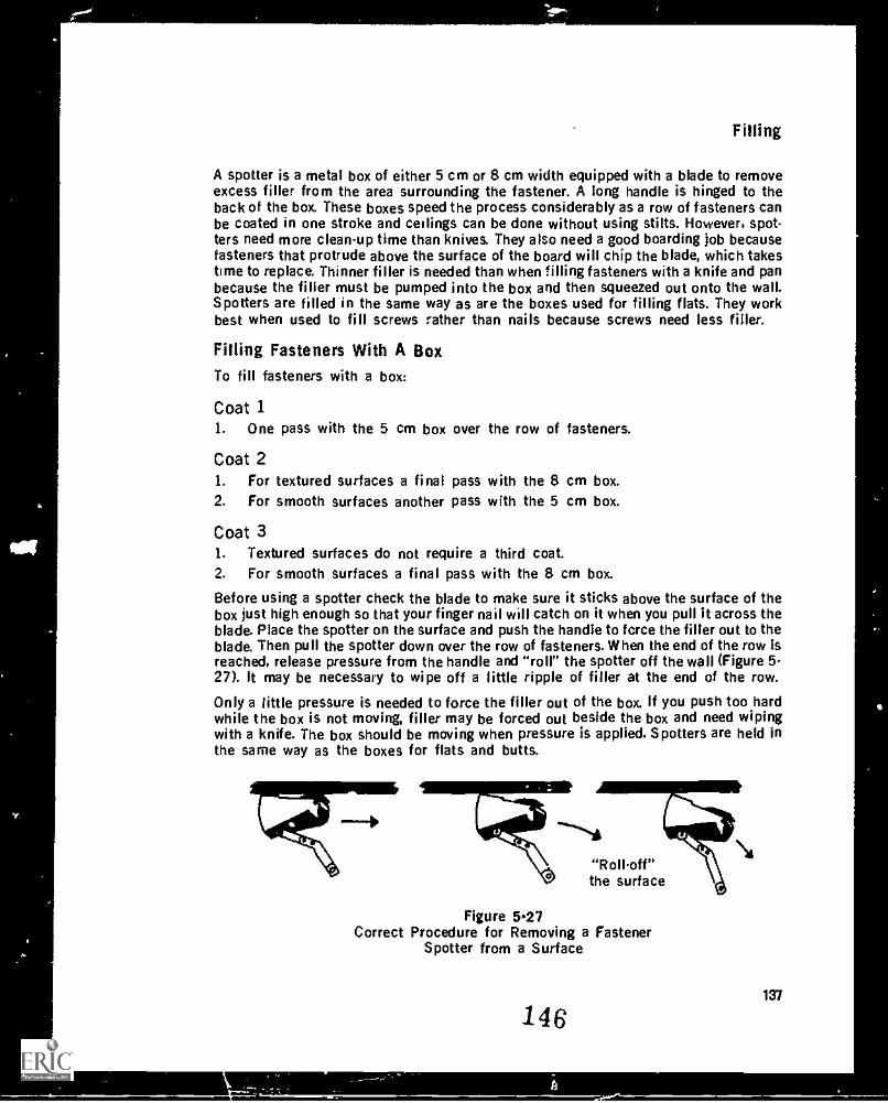
Filling
A spotter is a metal box of either 5 cm or 8 cm width equipped with a blade to removeexcess filler from the area surrounding the fastener. A long handle is hinged to theback of the box. These boxes speed the process considerably as a row of fasteners canbe coated in one stroke and ceilings can be done without using stilts. However, spot-ters need more clean-up time than knives. They also need a good boarding job becausefasteners that protrude above the surface of the board will chip the blade, which takestime to replace. Thinner filler is needed than when filling fasteners with a knife and panbecause the filler must be pumped into the box and then squeezed out onto the wall.Spotters are filled in the same way as are the boxes used for filling flats. They workbest when used to fill screws rather than nails because screws need less filler.
Filling Fasteners With A BoxTo fill fasteners with a box:
Coat 11. One pass with the 5 cm box over the row of fasteners.
Coat 21. For textured surfaces a final pass with the 8 cm box.2. For smooth surfaces another pass with the 5 cm box.
Coat 31. Textured surfaces do not require a third coat.2. For smooth surfaces a final pass with the 8 cm box.
Before using a spotter check the blade to make sure it sticks above the surface of thebox just high enough so that your finger nail will catch on it when you pull it across theblade. Place the spotter on the surface and push the handle to force the filler out to theblade. Then pull the spotter down over the row of fasteners. When the end of the row isreached, release pressure from the handle and "roil" the spotter off the wall (Figure 527). It may be necessary to wipe off a little ripple of filler at the end of the row.
Only a little pressure is needed to force the filler out of the box. If you push too hardwhile the box is not moving, filler may be forced out beside the box and need wipingwith a knife. The box should be moving when pressure is applied. Spotters are held inthe same way as the boxes for flats and butts.
47711:---....."Roll.off"the surface
Figure 5.27Correct Procedure for Removing a Fastener
Spotter from a Surface
146137
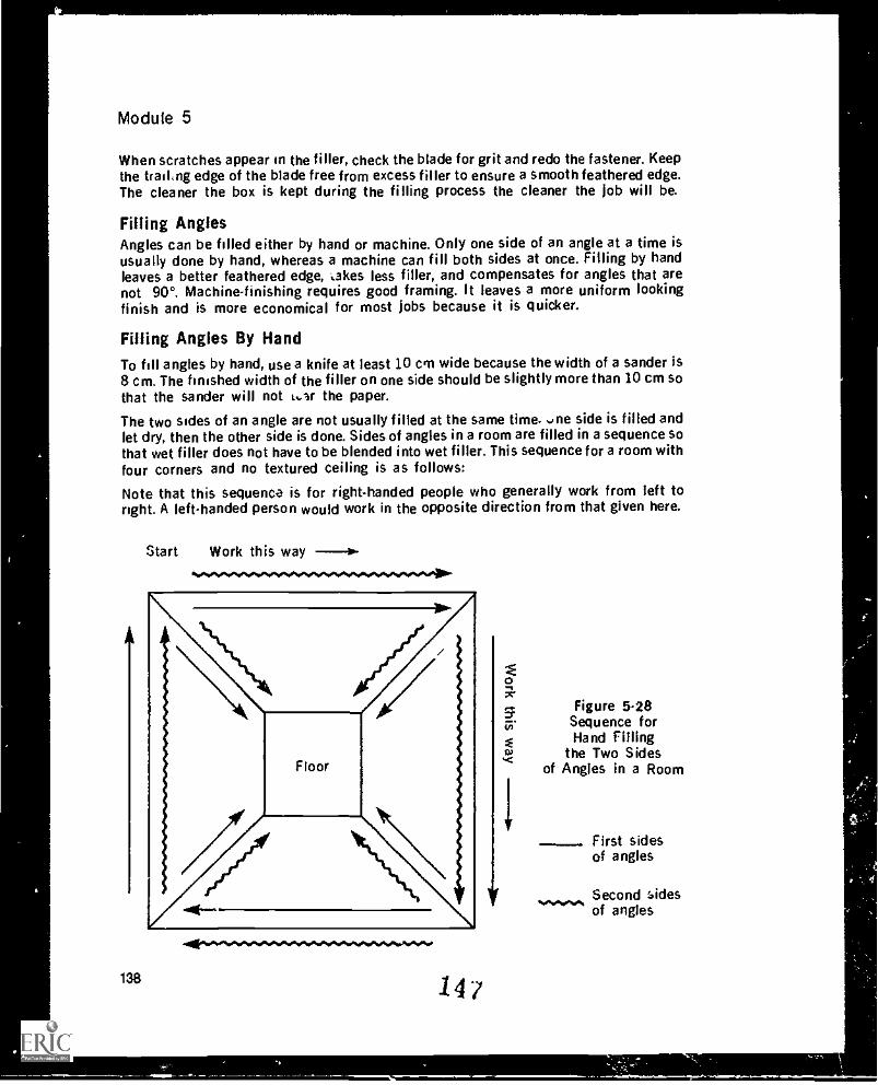
Module 5
When scratches appear in the filler, check the blade for grit and redo the fastener. Keepthe trailing edge of the blade free from excess filler to ensure a smooth feathered edge.The cleaner the box is kept during the filling process the cleaner the job will be.
Filling AnglesAngles can be filled either by hand or machine. Only one side of an angle at a time isusually done by hand, whereas a machine can fill both sides at once. Filling by handleaves a better feathered edge, takes less filler, and compensates for angles that arenot 90°. Machine-finishing requires good framing. It leaves a more uniform lookingfinish and is more economical for most jobs because it is quicker.
Filling Angles By HandTo fill angles by hand, use a knife at least 10 cm wide because the width of a sander is8 cm. The finished width of the filler on one side should be slightly more than 10 cm sothat the sander will not t...3r the paper.
The two sides of an angle are not usually filled at the same time. -me side is filled andlet dry, then the other side is done. Sides of angles in a room are filled in a sequence sothat wet filler does not have to be blended into wet filler. This sequence for a room withfour corners and no textured ceiling is as follows:
Note that this sequence is for right-handed people who generally work from left toright. A left-handed person would work in the opposite direction from that given here.
Start Work this way --1.-..............................".
+40..".004.04.",""4"04,138 247
1
Figure 5-28Sequence forHand Filling
the Two Sidesof Angles in a Room
First sidesof angles
._._,.rte. Second :Ad._._,.rte_._._,.rte
of angles
Filling
First Sides of Angles (Solid lines on Figure 5-28)1. Left side vertical angle, wall angle to second threeway.2. Right side vertical angle, ceiling angle to third threeway.3. Left side vertical angle, wall angle to fourth threeway.4. Right side vertical angle, ceiling angle back to starting threeway.
Second Sides of Angles (Wiggly lines on Figure 5-28)1. Right side vertical angle, ceiling angle to second threeway.2. Left side vertical angle, wall angle to third threeway.3. Right side vertical angle, ceiling angle to fourth threeway.4. Left side vertical angle, wall angle back to starting threeway.
If a ceiling is to be textured, only the wall angle has to be filled. However, the ceilingangle should be checked for edges and fasteners that need filling.
Filling both sides of an angle at the same time by hand takes practice and a steadyhand to ensure that filler on the opposite side is not gouged out. This is possible onsmall Jobs with few angles but not practical for large jobs.
Note that some finishers prefer to fill the top angles by hand and the vertical ones bymachine. This leaves a wider fill on the top angle which is easier to sand. With thissystem the top angles are filled when second coating and the vertical angles on thethird coat.
First Coat On AnglesBefore the first coat and between successive coats, remove bumps, ridges, or otherirregularities either by scraping with a bladi or by rough sanding.1. Depending on the drying conditions, load the entire length of one side of the
angle. On vertical angles the filler should be tight to the bottom of the angle andto the ceiling, and on horizontal angles tight to the wall at either end. A maximumof 1 mm of filler should be applied, enough to just cover the tape. More than 1 mmwill leave air bubbles in the filler and likely cause the corner to crack from abuild-up of filler.
2. Ideally, one pass of the knife should feather the edge, smooth the filler, and cleanoff the excess filler from the other side of the angle. However, if you can't do it inone pass, do it in two: one to feather, a second to smooth and to remove the ex-cess from the other side.
3. When the first sides of the angles are dry repeat the same procedures for thesecond sides of the angles. Note, gouging and tearing of the filler are signs thatthe first sides are not dry.
Second and Third CoatsThere are no second and third coats on angles for two reasons:1. The narrow width of tape does not require a wide fill to blend it into the wall.2. A second coat can build up in the angle and cause hairline cracking in the filler.
148139
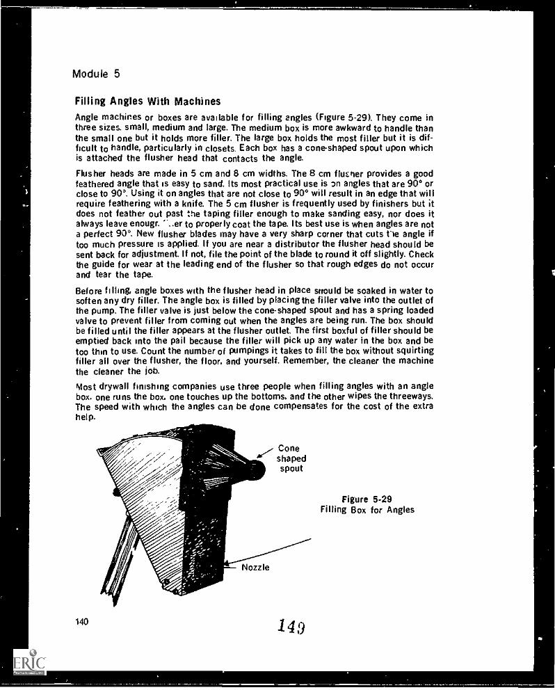
Module 5
Filling Angles With MachinesAngle machines or boxes are available for filling angles (Figure 5-29). They come inthree sizes. small, medium and large. The medium box is more awkward to handle thanthe small one but it holds more filler. The large box holds the most filler but it is dif-ficult to handle, particularly in closets. Each box has a cone-shaped spout upon whichis attached the flusher head that contacts the angle.
Flusher heads are made in 5 cm and 8 cm widths. The 8 cm flusher provides a goodfeathered angle that is easy to sand. Its most practical use is 2n angles that are 90° orclose to 90°. Using it on angles that are not close to 90° will result in an edge that willrequire feathering with a knife. The 5 cm flusher is frequently used by finishers but itdoes not feather out past the taping filler enough to make sanding easy, nor does italways leave enougr. '...er to properly coat the tape. Its best use is when angles are nota perfect 90°. New flusher blades may have a very sharp corner that cuts Vie angle iftoo much pressure is applied. If you are near a distributor the flusher head should besent back for adjustment. If not, file the point of the blade to round it off slightly. Checkthe guide for wear at the leading end of the flusher so that rough edges do not occurand tear the tape.
Before filling, angle boxes with the flusher head in place snould be soaked in water tosoften any dry filler. The angle box is filled by placing the filler valve into the outlet ofthe pump. The filler valve is just below the cone-shaped spout and has a spring loadedvalve to prevent filler from coming out when the angles are being run. The box shouldbe filled until the filler appears at the flusher outlet. The first boxful of filler should beemptied back into the pail because the filler will pick up any water in the box and betoo thin to use. Count the number of pumpings it takes to fill the box without squirtingfiller all over the flusher, the floor. and yourself. Remember, the cleaner the machinethe cleaner the job.
Most drywall finishing companies use three people when filling angles with an anglebox. one runs the box. one touches up the bottoms. and the other wipes the threeways.The speed with which the angles can be done compensates for the cost of the extrahelp.
Coneshapedspout
140
Nozzle
149
Figure 5-29Filling Box for Angles
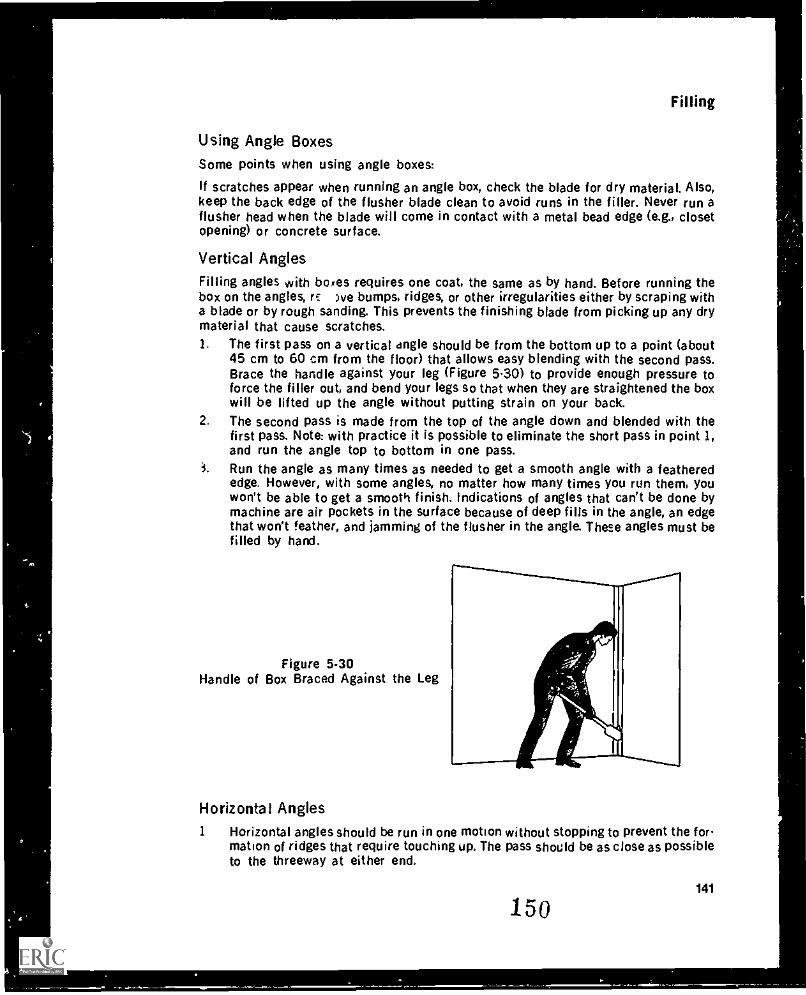
Filling
Using Angle BoxesSome points when using angle boxes:
If scratches appear when running an angle box, check the blade for dry material. Also,keep the back edge of the flusher blade clean to avoid runs in the filler. Never run aflusher head when the blade will come in contact with a metal bead edge (e.g., closetopening) or concrete surface.
Vertical Angles
Filling angles with boxes requires one coat, the same as by hand. Before running thebox on the angles, rE )ve bumps, ridges, or other irregularities either by scraping witha blade or by rough sanding. This prevents the finishing blade from picking up any drymaterial that cause scratches.1. The first pass on a vertical angle should be from the bottom up to a point (about
45 cm to 60 cm from the floor) that allows easy blending with the second pass.Brace the handle against your leg (Figure 5-30) to provide enough pressure toforce the filler out, and bend your legs so that when they are straightened the boxwill be lifted up the angle without putting strain on your back.
2. The second pass is made from the top of the angle down and blended with thefirst pass. Note: with practice it is possible to eliminate the short pass in point 1,and run the angle top to bottom in one pass.
i. Run the angle as many times as needed to get a smooth angle with a featherededge. However, with some angles, no matter how many times you run them, youwon't be able to get a smooth finish. Indications of angles that can't be done bymachine are air pockets in the surface because of deep fills in the angle, an edgethat won't feather, and jamming of the flusher in the angle. These angles must befilled by hand.
Figure 5-30Handle of Box Braced Against the Leg
11
Horizontal Angles1 Horizontal angles should be run in one motion without stopping to prevent the for
mation of ridges that require touching up. The pass should be as close as possibleto the threeway at either end.
150141
Module 5
2. Run the angle as many times as needed to get a smooth angle with a featherededge.
3. Note that horizontal angles in closets should be aone before the vertical angles sothat any filler that falls into the vertical angle can be picked up by the flusher.
Filling Bottoms anti ThreewaysThe person filling the bottoms is responsible for any edges and other irregularities inangles up to the 120 crri mark. The person filling the threeways is responsible forirregularities in angles (vertical and horizontal) above the 120 cm mark. It is importantto remove any edges and fill any scratches while the filler is still wet. If edges are letdry they will require a lot of sanding or two or three coats of filler to correct them.
Bottom angles should be filled with a knife that is wider than the filler left by theflusher, but not so wide as to make a feathered edge that will need extra sanding,
To Fill Bottoms1. Add a little filler to the bottom of one side of the angle and pull the knife up the
angle to blend in where the box left off.2. Feather the edge.3. Remove the excess filler.4. Rcpeat the same procedure for the other side, taking care not to gouge filler from
the other angle.
To Fill Threeways
1. With a 12 cm knife apply a little filler to one side of the angle on the ceiling. Startwith the ceiling so that any filler falling into the wall angle is removed when it iswiped.
2. Pull out the filler about 15 cm making sure to float over the wet filler on the in-tersecting angle and not to gcuge filler from the adjacent angle.
3. Feather the edge...
A Remove the excess.5. These four passes will fill the two sides of the ceiling angle. Repeat these four
passes on both walls to complete the threeway.
Filling Non 90° AnglesNon 90° angles are always filled by hand. The angle boxes cannot be used. Theprocedure for these a igles is the same as for 90° angles, but special care must betaken to ensure that the line of angle is straight. Frequently, non 90° angles are uniqueand attract attention. This makes it necessary to use more care when filling them.
Angles More Than 90°1. Pre-fill any high or hollow spots berore filling to level out the surface. Disregard
at this time what the prfilling does to the line of the angle.2. Place a straight edge (piece of bead, straight board, etc.) along one sir f the
angle the width of the knife from the angle, and run the knife along the ede to fill
142
151

Filling
this side of the angle. To get a straight line, make sure that the corner of the bladecontacts the straight edge.
3. When the first side of the angle is dry, repeat the procedure on the other side.
Flexible Bead In Angles More Than 90°The centre line of the flexible bead is an excellent guide for filling if it has been appliedproperly. Keep the corner of the knife in the angle so tnat the line of the angle isstraight (Figure 5.31). It is not necessary to fill into the angle as the metal will acceptand hold a painted finish. It is important, however, that the edges of the metal becovered and blended into the wall surface.
Figure 5-31Flexible Bead Used as a Straight
Edge for Filling
Angles Less Than 90°These angles are usually found under stairwells and in storage areas. They do notgenerally require special attention because:1. They are not prominent2. The tape is rarely creased properly and therefore the angle cannot be filled right
into the apex of the angle.3. The line of the angle cannot be seen clearly because of the shadow formed.
However, feather the edges keeping the edge straight and remove excess fillerfrom the angle.
Filling Rounded AnglesA wide flexible knife is essential for rounding angles. If the angle has been wiped roundto start vi"th, only a skim coat of filler is required to cover the tape. A straight edge canbe used tc, guide the knife down the angle, but it is not essential. To flii rounded angles:
152143
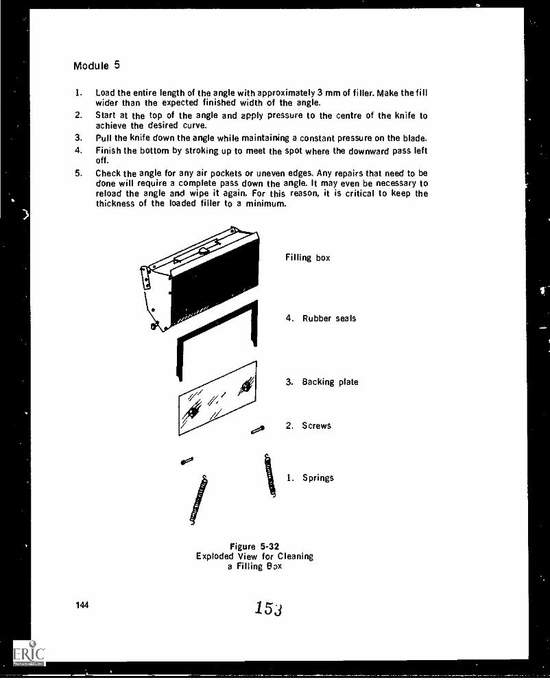
Module 5
1. Load the entire length of the angle with approximately 3 mm of filler. Make the fillwider than the expected finished width of the angle.
2. Start at the top of the angle and apply pressure to the centre of the knife toachieve the desired curve.
3. Pull the knife down the angle while maintaining a constant pressure on the blade.4. Finish the bottom by stroking up to meet the spot where the downward pass left
off.
5. Check the angle for any air pockets or uneven edges. Any repairs that need to bedone will require a complete pass down the angle. It may even be necessary toreload the angle and wipe it again. For this reason, it is critical to keep thethickness of the loaded filler to a minimum.
144
so
/ i
Filling box
4. Rubber seals
3. Backing plate
2. Screws
1. Springs
Figure 5-32Exploded View for Cleaning
a Filling Box
153
Filling
Tool CleanupBoxes for flats, angles and fasteners must be kept clean to operate efficiently. While agood washing with a water hose will do a fair job on a flat box, to be thoroughly cleanedthe back of the box must be taken apart (Figure 5-32). First remove the springs holdingthe back of the box in the upright position. Then unscrew the two screws that hold inthe back of the box until the back comes out. Note that some boxes have a tab that issimply moved to one side to remove tho back plate. To reassemble the box, the rubbersshould be in place with the thin piece at the pivot point. The square butt ends meet andform a tight joint at the top of the plate. The rounded edge of the backing plate fits onat the bottom end of the box which is the pivoting point. Wetting the rubber partsmakes them slide into the box easier when you install the backing plate. Fasten thescrews at the sides to hold in the back and hook up the springs. Store the box with thetension cam in the "0" position so that all pressure is taken off the blade. It is a goodidea to oil the wheels and blade adjusting screws at this point so the box will be readywhen needed.
Angle boxes are washed by pumping clean water through them. This cleans the valve aswell as the inside of the box. Splash some water inside the box to make sure all thefiller has been removed. On some angle boxes the back can be easily removed butothers are retained by screws. If the back can be removed, a better job can be done.Also wash the flusher head so that the blades are clean and move freely. It is also agood time to oil the flusher head blades and hinge.
To clean fastener spotters the box should be taken apart to remove all the filler fromthe inside and along the blade.
Finish SandingFinish sanding on walls is done after the ceiling is textured. It should be nothing morethan a light brushing of the surface of the board. A 100 or 120 grit paper should beused, depending on the type of decoration. The entire surface of the board should becovered to leave the surface smooth and flat. A hand sander may be used for detailsanding such as on the wall angle at the ceiling (top angle) and on threeways. The handsander is also useful during the final inspection of the job.
Note that it is desirable to sand rather than touch-up with filler because the touch-upwill require sanding. Also, sanding keys the filler so that the paint will adhere to it. Becareful, however, not to oversand as this can cause hollow spots in the filler which willshow up after decorating.
Wet sanding, although not common, is a special type of finish sanding. The purpose ofwet sanding, as with dry sanding, is to remove any minor imperfections and key thefiller. The tool used is a round sponge about 3 cm thick fixed to a flat disk with a hand-le. It is dipped into a very thin mixture of filler called slurry and applied to the wall witha circular motion. The thin filler fills in any blemishes on the surface and softens thefiller, enabling the sponge to remove any edges. Wet sanding can be done where dustmust be eliminated (for example, in additions to hospitals), and on surfaces that will bepainted with a highly reflective paint.
A skim coat of filler over the entire surface of the wall is a substitute for wet sandingand is more commonly done.
145
154
4
Module 5
Sanding Sequence
1. Start from one end of a wall.2. Sand the vertical angle:
Use light pressure and vertical strokes.Clean the line of the angle.Sand the edges.
3. Sand all the fasteners on the wall:Use very light pressure and vertical strokes.Watch for edges.Touch the edges of the flat(s).
4. Sand the butt joints:Use light pressure and vertical strokes.Hold the sander head horizontal for the centre of the butt and vertical for theedges.
5. Sand the top angle:Use moderate pressure and horizontal strokes.Keep the edge of the sander away from texture on the ceiling.Concentrate on the edges of the angle.
6. Sand the flat(s):Sand the centre of the joint first.Use moderate pressure on the centre of the joint and hold the sander head vet.-tical.Sand the edges of the flat with light pressure and the sander head horizontal.
In general the entire surface of the wall should be sanded. The sandpaper should brushvery lightly over the bare paper of the wallboard. You should not use the same pressureon the bare paper as is used over the filled areas. The entire surface must be coveredso that any spilled filler or texture overspray is removed.
The amount of sanding required will be directly proportional to the quality of the fillingjob. A good finisher will have little sanding to do.
Final InspectionFinal inspection requires a thorough knowledge of the trade. Otherwise problem areaswill be overlooked. The closeness of the inspection will depend on the type of finishgoing on the wallboard. Normally, a high-wattage light bulb (200 W) in a light extensioncord is needed to inspect surfaces that require a highly reflective tinsel. A 200 W bulbis recommended because it throws enough light to cast a definite shadow. The lightshould he held at arm's length and pass parallel over the surface. This will createshadows where any scratches or ridges, waves or holtows, may be. A 100 W or 150 Wbulb is adequate to inspect a surface to be finished with a flat latex paint.
146
153
Filling
Practical ChecklistFollowing is a checklist for examining your own work:
1. Are the filler edges straight and parallel?2. Are the edges feathered?3. Are tapes, beads and fasteners covered properly?4. is the surface smooth?5. is the surface full according to the specifications?6. Have irregular surfaces been filled level?7. Are bead edges clean?8. Has the filler dried in a uniform band?9. Have all joints and beads been sanded?
10. Has the entire surface of the wall been covered during finish sanding?11. Have all edges been removed?12. Has the required touching up been done?
SUMMARY
Find out the type of finish to be applied to the drywall and with that informationdecide on the number of coats that need to be applied.Filler should be dry before being re coated.Never sand without a mask. The mask must meet W.C.B. standards.
Coats of Filler
First Coat
Loading coat on beads, butts and fasteners.Thick filler is used.The angle of the blade is less than 45°.Surface should not be rippled or ridged.
Second Coat
Fills shrinkage from first coat.Thinner filler than first coat, usually topping filler.The angle of the blade is 45°.
Third Coat
Leave a smooth finish.Thin mix of filler.The angle of the blade is greater than 45°.
156 147
e
Module 5
Skim Coat
Use thin filler and change the filler on the blade as often as necessary.Leave only a film of filler on the wall.Skim parallel to filled fasteners, joints, angles and beads.
Filling Passes (or Strokes)
Loading Pass
Load the joint uniformly to the approximate width of the fill.Make only one pass over an area.Decrease the angle of the blade as the blade moves forward.
Feathering Pass
Blends the edges of the fiiler into the wallboard.Use a flexible blade for feathering.Place the blade end on the outside edge of the fill, not beyond it.
Removing the Excess
Removes filler to establish the depth of the fill.Bead should be full.The surface should be level and free of ridges or lines.
Rough Sanding
Rough sand with 80 grit paper or by scraping with a blade.Remove all edges and ridges in the filler between coats.Do not sand so much that the tape becomes exposed.
Finish Sanding
Finish sanding with 100 or 120 grit paper.Remove any edges or ridges in the filler.The entire wall should be touched with the sander.
Filling BeadBefore the first coat and between successive coats, remove any bumps, ridges, or otherirregularities either by scraping with a blade or by rough sanding.
The first coat on the bead should be no wider than 25 cm.Each successive coat should cover the edge of the preceding coat.The width of finished bead should be approximately 30 cm.The bead must be full over the width of the fill.Tops of bead must be done while the bottoms are still wet to avoid cracking wheretops join the bottoms.
148
157I
Filling
Leave es few ridges or edges as possible.Fill tight to the floor and to the ceiling.Level out the filler where the bead is joined.Clean off the finishing edge of bead immediately after filling the bead.
Filling ButtsBefore the first coat and between successive coats, remove any bumps, ridges, or otherirregularities either by scraping with a blade or by rough sanding.
The tirst coat should cover the tape (a thin coat) and be about 25 cm wide.The second coat is on either side of the tape (not over the tape) and should beabout 60 cm wide overall.The . iird coat, if there is one, is a thin polish coat that covers the entire surface ofthe butt, leaving a 60 to 75 cm finished width.Leave as few ridges or edges as possible.Finished butt joints should make a smooth, level surface with the rest of the wallto within 2 mm in 1200 mm.
Filling Butts By Machine
Before the first coat and between successive coats, remove any bumps, ridges, or otherirregularities either by scraping with a blade or by rough sanding.
Uneven butts should not be run by machine.Check for the correct blade heightThree coats are required.The first coat is done with the 25 cm box, the second and third with the 30 cmbox.
Make sure you do not overfill the tape.
Filling FlatsBefore the first coat and between successive coats, remove bumps, ridges, or otherirregularities either by scraping with a blade or by rough sanding.
The first coat should cover the tape and be no wider than 25 cm.With high shrinkage fillers, leave 1 mm to 2 mm build-up; with low shrinkagefillers leave the filler level with the board, and with non-shrinking fillers (i.e., fast-set) leave the fill slightly hollow.Successive coats should cover the previous coat with the final coat being ap-proximately 30 cm wide.Fill flats right over butts, and tight to angles and to the finishing edge of beads.Leave as few ridges or edges as possible.Finished flats should be level with the surface of the board to within 2 mm in1200 mm,
158149
4
f
-
Module 5
Filling Flats By Machine
Before the first coat and between successive coats. remove bumps, ridges, or otherirregularities either by scraping with a blade or by rough sanding.
Two or three coats are required depend ; on the type of decoration.The most common combination of boxes ib a 25 cm for the first coat and a 30 cmfor the :inishing coat(s).Check for the correct blade height.Use the appropriate consistency of filler for the coat being applied and the rightmachine setting.Use the proper grip that does not put undue stress on your back or arms.Apply pressure only when the box is moving and keep the box perpendicular to thejoint.Keep the blade free of hard or excess material.Touch up at the ends of the joints and where the box is lifted off the joint whilethe Wier is still wet.
Filling AnglesRough sand after taping if necessary.Angles require one coat.When filling angles by hand the second side of the angle can't be filled until thefirst side is dry.The angles in a room are done by hand in a set sequence to avoid blending withwet fillerApply the least amount of filler as possible over the tape, a maximum of 1 mm.Fill threeways so that they are square and smooth and have feathered edges.
Filling Angles With Machines
1. The 8 cm flusher head is best to use on angles.2. Check the leadirg edge of the flusher for rough edges that could tear the tape.3. Keep the back -3dge of the flusher blade clean.4. Grip the angle box in the proper way so that undue stress is not put on your arms
or back.5. Angle bottoms and threeways have to be wiped by hand while the filler from the
machine is still wet.
Filling FastenersUsually three coats are required to fill fasteners.
Each coat should completely cover the edges of the preceding one, and only askim coat should be on the board.Do not build up filler over fasteners.Repair defects on the surface of the board around the fasteners.Pre.f ill nails in ioints and near angles and beads.
150
159
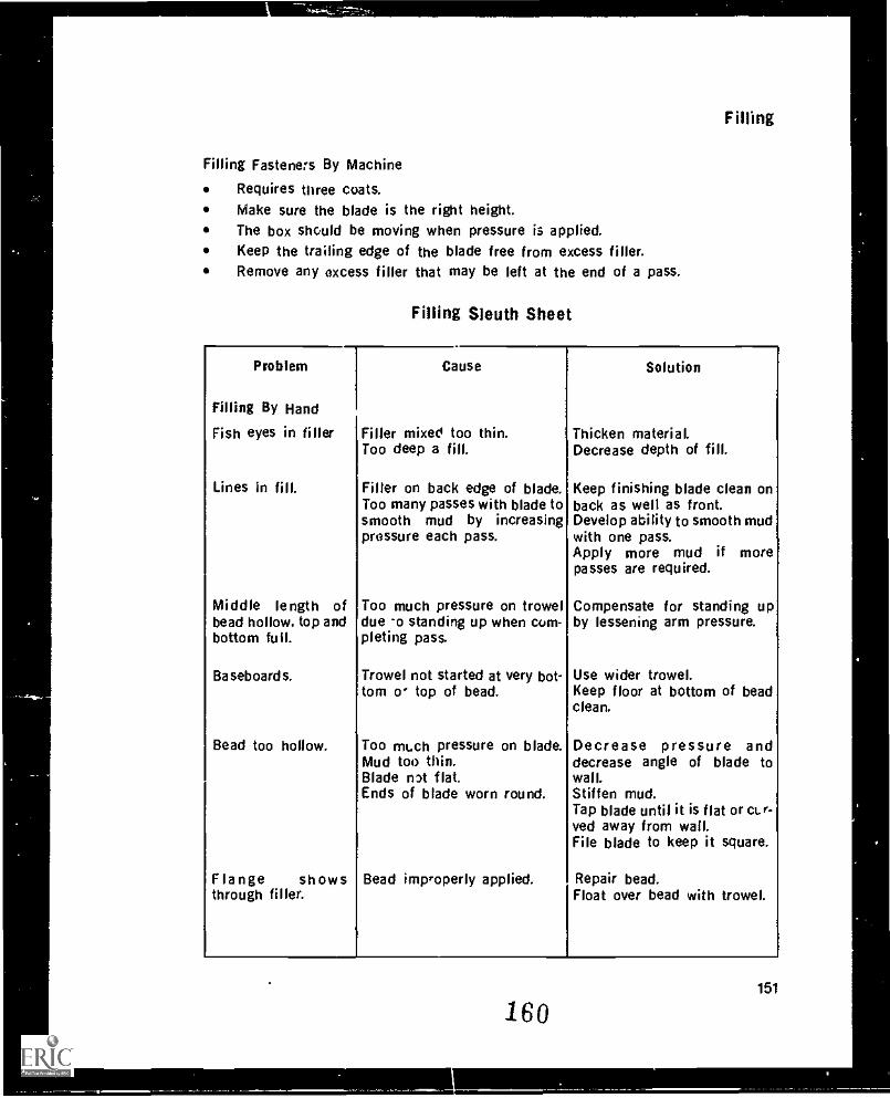
Filling
Filling Fasteners By Machine
Requires three coats.Make sure the blade is the right height.The box should be moving when pressure is applied.Keep the trailing edge of the blade free from excess filler.Remove any excess filler that may be left at the end of a pass.
Filling Sleuth Sheet
Problem
Filling By Hand
Fish eyes in filler
Lines in fill.
Middle length ofbead hollow, top andbottom full.
Baseboards.
Bead too hollow.
Flange showsthrough filler.
Cause
Filler mixed too thin.Too deep a fill.
Filler on back edge of blade.Too many passes with blade tosmooth mud by increasingpressure each pass.
Too much pressure on troweldue -o standing up when com-pleting pass.
Trowel not started at very bot-tom o' top of bead.
Too mt.ch pressure on blade.Mud too thin.Blade nit flat.Ends of blade worn round.
Bead improperly applied.
Solution
Thicken material.Decrease depth of fill.
Keep finishing blade clean onback as well as front.Develop ability to smooth mudwith one pass.Apply more mud if morepasses are required.
Compensate for standing upby lessening arm pressure.
Use wider trowel.Keep floor at bottom of beadclean.
Decrease pressure anddecrease angle of blade towall.Stiffen mud.Tap blade until it is flat or ct.r-ved away from wall.File blade to keep it square.
Repair bead.Float over bead with trowel.
160151
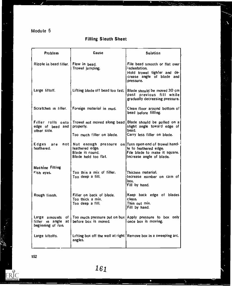
Module 5
Filling Sleuth Sheet
Prob:em Cause Solution
Ripple in bead filler. Flaw in bead,Trowel jumping.
File bead smooth or flat overindentation.Hold trowel tighter and de-crease angle of blade andpressure.
Large liftoff. Lifting blade off bead too fast. Blade should be moved 30 cmpast previous fill whilegradually decreasing pressure.
Scratches in filler. Foreign material in mud. Clean floor around bottom ofbead before filling.
Filler rolls onto Trowel not moved along bead Blade should be pulled on aedge of bead and properly. slight angle toward edge ofother side. bead.
Too much filler on blade. Carry less filler on blade.
Edges are not Not enough pressure on Turn open end of trowel hand-1feathered. feathered edge. le to feathered edge.
Blade is round. File blade to make it square.Blade held too flat. Increase angle of blade.
Machine FillingFish eyes. Too thin a mix of filler. Thicken material.
Too deep a fill. Increase number on cam ofbox.Fill by hand.
Rough finish. Filler on back of blade. Keep back edge of bladesToo thick a mix. clean.Too deep a fill. Thin out mix.
Fill by hand.
Large amounts of Too much pressure put on box Apply pressure to box onlyfiller in angle atbeginning of run.
before box is moved. once box is moving.
Large liftoffs. Lifting box off the wall at rightangles.
Remove box in a sweeping arc.
152
161MN/
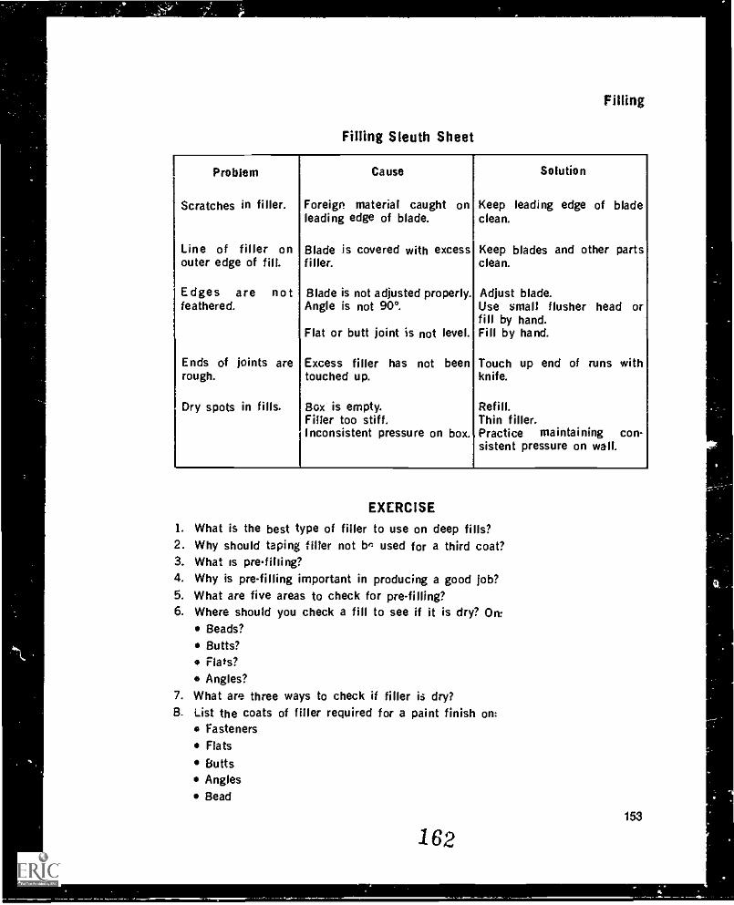
Filling
Filling Sleuth Sheet
IProblem Cause Solution
Scratches in filler. Foreign material caught on Keep leading edge of bladeleading edge of blade. clean.
Line of filler on Blade is covered with excess Keep blades and other partsouter edge of fill. filler. clean.
Edges are no t Blade is not adjusted properly. Adjust blade.feathered. Angle is not 90°. Use small flusher head or
fill by hand.Flat or butt joint is not level. Fill by hand.
Ends of joints are Excess filler has not been Touch up end of runs withrough. touched up. knife.
Dry spots in fills. Box is empty. Refill.Filler too stiff. Thin filler.Inconsistent pressure on box. Practice maintaining con-
sistent pressure on wall.
EXERCISE
1. What is the best type of filler to use on deep fills?2. Why should taping filler not bn used for a third coat?3. What is prefiliing?4. Why is pre-filling important in producing a good job?5. What are five areas to check for pre-filling?6. Where should you check a fill to see if it is dry? On
Beads?
Butts?Flats?
Angles?7. What are three ways to check if filler is dry?8. List the coats of filler required for a paint finish on:
Fasteners
Flats
ButtsAnglesBead
153
162
Module 5
9. List the coats of filler required for a textured finish on:Fasteners
Flats
ButtsAnglesBead
10. How much filler should be left on a loading coat for:Powdered filler?Pre-mix filler?Fast-setting filler?
11. What should a first coat look like?12. What should a second coat look like?13. What should a third or polish coat look like?14. What are the purposes of a skim coat?15. When is a skim coat necessary?16. What should a good skim coat look like?17. Using a knife requires a combination of what two things?18. What is the proper grip for holding a trowel?19. What are the four basic passes for filling?20. When making a loading pass, the angle of the blade to the wall is and
the pressure is .
21. What is the purpose of the feathering pass?22. After removing the excess, the fill should be23. What should be done to remove lumps and ridges between coats of fill?24. Where is a hand sander often used when finish sanding?25. How should a loading pass on bead be finished off?26. On vertical bead, why should the excess be removed upwards rather than down-
wards?
27. What must be done when intersecting bead is not flush?28. What technique should be used when removing excess filler from bead around
windows and archways?29. What is the mem difference between filled joints on flat and curved surfaces?30. What must be done when filling uneven butts?31. What is the approximate finished width of a butt joint? A flat joint?32. if the full width of the tape can be seen within a few minutes of filling a flat, what
has been done wrong?33, How do you correct a filling box that is not feathering properly?34. What combination of boxes is accepted as standard for filling butts and flats?35. When starting a joint with a box, when do you apply pressure in relation to moving
the box?
154
163
(
Filling
36. How is pressure applied to a filling box on a ceiling?37. How many coats should be applied to fasteners?38. What sequence of knifes is recommended for filling fasteners by hand?39. What is the sequence of boxes used for filling fasteners for a smooth finish? A tex-
tured finish?40. Why should you use a knife at least 10 cm wide to wipe angles by hand?41. How much filler should be applied when loading an angle by hand?42. True or False? It may be necessary to run an angle several times with an angle box
to get a smooth, feathered angle.43. True or False? If you get really good with an angle box, you can do the bottoms and
threeways with it.44. What technique is used to get a straight line in an angle that is more than 90°?45. How much filler should be loaded on an angle that is to be rounded?46. Before cleaning a filling box, what must be done to do a thorough cleaning job?47. What is the sanding sequence for a wall?48. What is needed to carry out a final inspection of a drywall finishing job?
164155
4
TexturingMODULE 6
INTRODUCTION
Texture is sprayed on ceilings and walls by machine in a wide assortment of patter's.Texture can also be applied by hand and trowelled or tooled into patterns, shapes,geometric designs or virtually any design the finisher can dream up. Texture requiresan undercoating of paint and the texture itself can be white or colored. The point tonote about texture is that in most cases it is the final decoration for the wall andtherefore must be done well.
There is a misconception as to the acoustic value of texture. Texture is primarilydecorative; it provides little soundproofing. True acoustic materials must be sprayed ortrowelled on at a thickness of 1 cm or more to be effective. Since drywall textures aresprayed on at a thickness of 2 mm to 3 mm, the amount of sound absorption isminimal.
Types Of Wallboard TextureThree types of texture materials are used in the industry: hard, soft. and self-priming.Hard texture consists of a binder and limestone, a formulation similar to fillers. It mayalso contain an aggregate. It dries hard and is very white. When hard it is slow to takeon moisture, making it good for use in rooms with moderate moisture conditions. Oncedry, hard texture is very resistant to wear making it suitable for walls. Because hardtexture does not cover t'-2 entire surface of the wall, it requires an undercoat as abackground. Hard texture is used for orange peel texture, splatter coats, hand-appliedtextures, and knockdown finishes.
Soft texture consists of a binder, limestone for color, and a cryotaline porous materialcalled perlite for decora. . ince the perlite particles are easily rubbed off, soft tex-ture is used only on ceiling,. Soft texture is .-t--)t suitable where moisture is presentsuch as in bathrooms because perlite is porous and absorbent. Soft texture covers theentire surface of the ceiling but contains no pigment to seal the surface. It thereforerequires al, undercoat of good sealer. Owing to the larger size of its particles, soft tex-ture is superior to hard textures in hiding ability.Self-primilg texture contains a decorative polystyrene chip aggregate. The chips aresimilar ir; appearance to acoustic textures, but they have no real sound-deadeningability. Because the aggregate can be easily rubbed off, self-priming texture is usedonly on ceilings. No undercoat is required because the texture contains a powderedlatex paint. Since the polystyrene chips do not absorb water, self-priming texture isgc--ol for bathrooms and kitzhens.
165
157
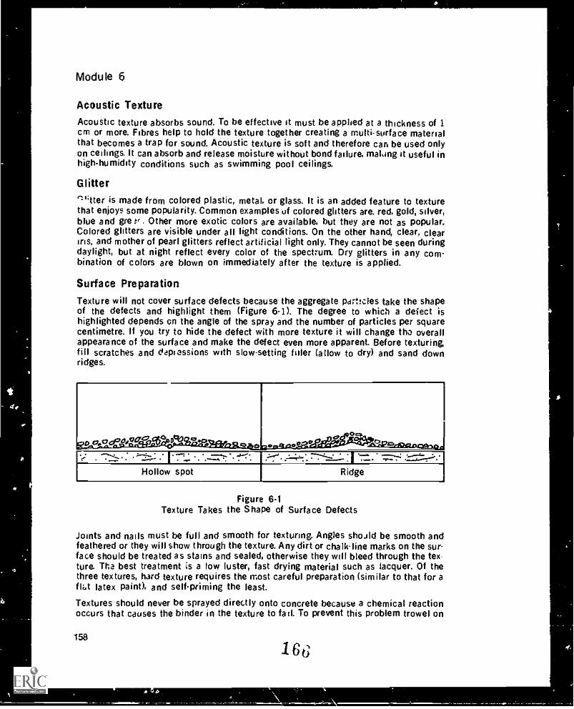
or
Module 6
Acoustic Texture
Acoustic texture absorbs sound. To be effective it must be applied at a thickness of 1cm or more. Fibres help to hold the texture together creating a multi- surface materialthat becomes a trap for sound. Acoustic texture is soft and therefore can be used onlyon ceilings. It can absorb and release moisture without bond failure, malong it useful inhigh-humidity conditions such as swimming pool ceilings.
Glitterfli;ner is made from colored plastic, metal, or glass. It is an added feature to texturethat enjoys some popularity. Common examples of colored glitters are. red, gold, silver,blue and gre . Other more exotic colors are available, but they are not as popular.Colored glitters are visible under all light conditions. On the other hand, clear, cleariris, and mother of pearl glitters reflect artificial light only. They cannot be seen duringdaylight, but at night reflect every color of the spectrum. Dry glitters in any com-bination of colors are blown on immediately after the texture is applied.
Surface Preparation
Texture will not cover surface defects because the aggregate pert!eles take the shapeof the defects and highlight them (Figure 6-1). The degree to which a defect ishighlighted depends on the angle of the spray and the number of particles per squarecentimetre. If you try to hide the defect with more texture it will change th. overallappearance of the surface and make the defect even more apparent. Before texturing,fill scratches and depressions with slow-setting filler (allow to dry) and sand downridges.
-0 cr,a,00o,00.4".., 55,, 49 4, ....._ . , CII *
Cli- -....,v; - ,.. -,g
. c - - -' .reeEeeszfitsiciawag,
Hollow spot Ridge
Figure 6.1Texture Takes the Shape of Surface Defects
Joints and nails must be full and smooth for texturing. Angles should be smooth andfeathered or they will show through the texture. Any dirt or chalk-line marks on the sur-face should be treated as stains and sealed, otherwise they will bleed through the tex-ture. Tha best treatment is a low luster, fast drying material such as lacquer. Of thethree textures, hard texture requires the most careful preparation (similar to that for aflat latex paint), and selfpriming the least
Textures should never be sprayed directly onto concrete because a chemical reactionoccurs that causes the binder in the texture to fail. To prevent this problem trowel on
158
166
4)
AP.
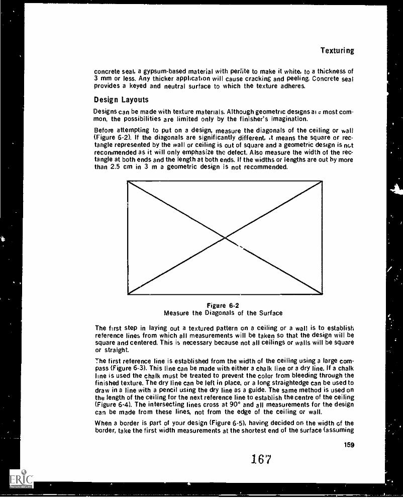
Texturing
concrete seal, a gypsum-based material with perlite to make it white, to a thickness of3 mm or less. Any thicker application will cause cracking and peeling. Concrete sealprovides a keyed and neutral surface to which the texture adheres.
Design Layouts
Designs can be made with texture materials. Although geometric designs ai c most com-mon, the possibilities are limited only by the finisher's imagination.
Before attempting to put on a design, measure the diagonals of the ceiling or wall(Figure 6-2). If the diagonals are significantly different, ,t means the square or rec-tangle represented by the wall or ceiling is out of square and a geometric design is riGtrecommended as it will only emphasize the defect. Also measure the width of the rec-tangle at both ends and the length at both ends. If the widths or lengths are out by morethan 2.5 cm in 3 m a geometric design is not recommended.
Figure 6-2Measure the Diagonals of the Surface
The first step in laying out a textured pattern on a ceiling or a wall is to establishreference lines from which all measurements will be taken so that the design will besquare and centered. This is necessary because not all ceilings or walls will be squareor straight.
The first reference line is established from the width of the ceiling using a large com-pass (Figure 6-3). This line can be made with either a chalk line or a dry line. If a chalkline is used the chalk must be treated to prevent the color from bleeding through thefinished texture. The dry line can be left in place, or a long straightedge can be used todraw in a line with a pencil using the dry line as a guide. The same method is used onthe length of the ceiling for the next reference line to establish the centre of the ceiling(Figure 6-4). The intersecting lines cross at 90° and all measurements for the designcan be made from these lines, not from the edge of the ceiling or wall.
When a border is part of your design (Figure 6-5), having decided on the width of theborder, take the first width measurements at the shortest end of the surface (assuming
167159
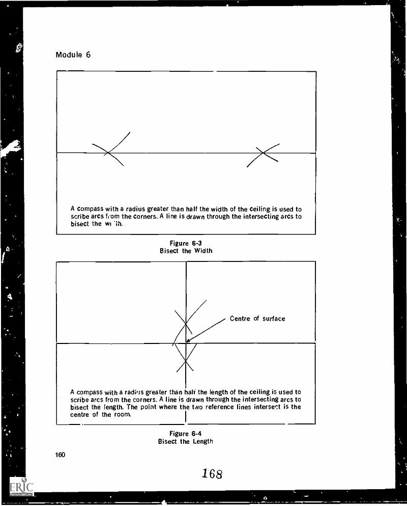
Module 6
A compass with a radius greater than half the width of the ceiling is used toscribe arcs fiorn the corners. A line is drawn through the intersecting arcs tobisect the wi Th.
Figure 6-3Bisect the Width
Centre of surface
A compass with a radiqs greater than half the length of the ceiling is used toscribe arcs from the corners. A line is drawn through the intersecting arcs tobisect the length. The point where the two reference lines intersect is thecentre of the room.
I
160
Figure 6-4Bisect the Length
168
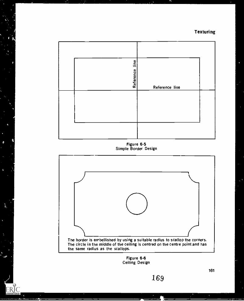
Texturing
4)c=4)0Ct124)
....4)
elt: Reference line
I
Figure 6.5Simple Border Design
0r
The border is embellished by using a suitable radius to scallop the corners.The circle in the middle of the ceiling is centred on the centre point and hasthe same radius as the scallops.
Figure 6.6Ceiling Design
169161
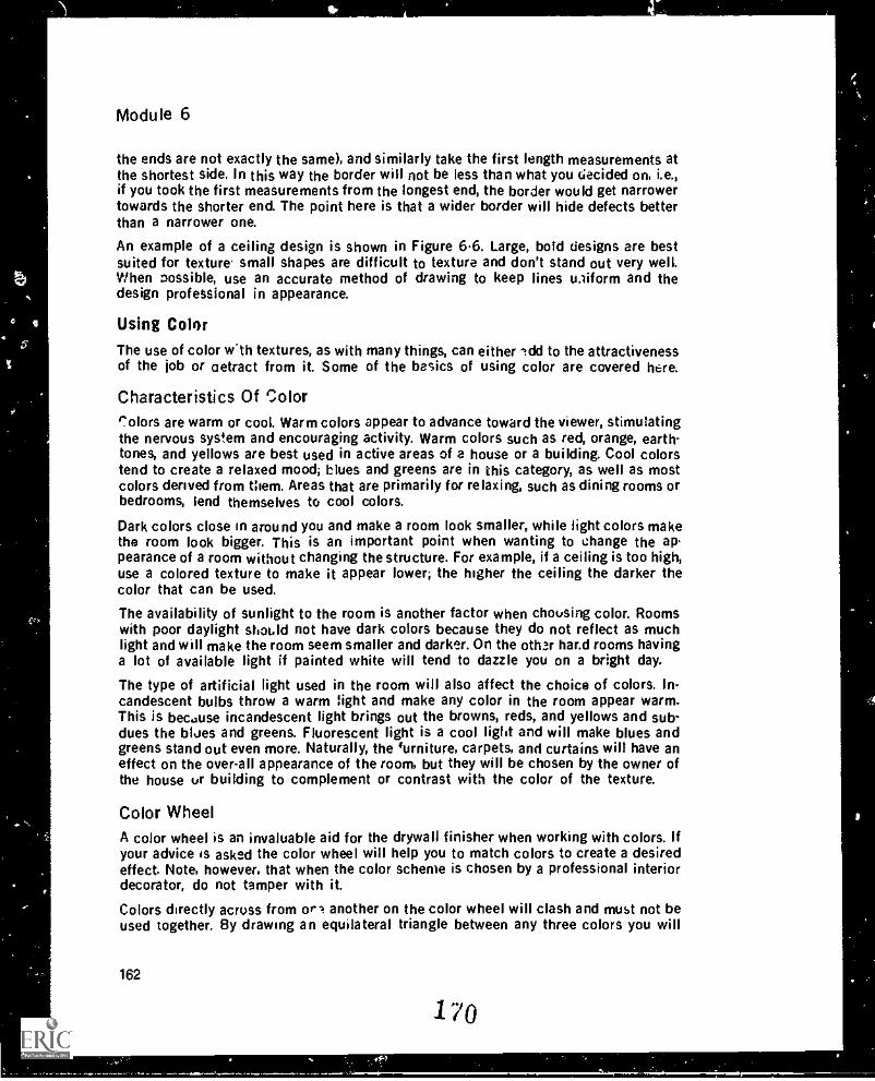
Module 6
the ends are not exactly the same), and similarly take the first length measurements atthe shortest side. In this way the border will not be less than what you decided on, i.e.,if you took the first measurements from the longest end, the border would get narrowertowards the shorter end. The point here is that a wider border will hide defects betterthan a narrower one.
An example of a ceiling design is shown in Figure 6.6. Large, bold designs are bestsuited for texture. small shapes are difficult to texture and don't stand out very well.When possible, use an accurate method of drawing to keep lines uniform and thedesign professional in appearance.
Using Color
The use of color w'th textures, as with many things, can either ldd to the attractivenessof the job or (retract from it. Some of the basics of using color are covered here.
Characteristics Of Colorr_'olors are warm or cool. Warm colors appear to advance toward the viewer, stimulatingthe nervous system and encouraging activity. Warm colors such as red, orange, earth-tones, and yellows are best used in active areas of a house or a building. Cool colorstend to create a relaxed mood; blues and greens are in this category, as well as mostcolors derived from them. Areas that are primarily for relaxing, such as dining rooms orbedrooms, lend themselves to cool colors.
Dark colors close in around you and make a room look smaller, while light colors makethe room look bigger. This is an important point when wanting to change the appearance of a room without changing the structure. For example, if a ceiling is too high,use a colored texture to make it appear lower; the higher the ceiling the darker thecolor that can be used.
The availability of sunlight to the room is another factor when choosing color. Roomswith poor daylight should not have dark colors because they do not reflect as muchlight and will make the room seem smaller and darker. On the oth.r har.d rooms havinga lot of available light if painted white will tend to dazzle you on a bright day.
The type of artificial light used in the room will also affect the choice of colors. In-candescent bulbs throw a warm light and make any color in the room appear warm.This is because incandescent light brings out the browns, reds, and yellows and sub-dues the blues and greens. Fluorescent light is a cool light and will make blues andgreens stand out even more. Naturally, the iurniture, carpets, and curtains will have aneffect on the over-all appearance of the room, but they will be chosen by the owner ofthe house or building to complement or contrast with the color of the texture.
Color Wheel
A color wheel is an invaluable aid for the drywall finisher when working with colors. Ifyour advice is asked the color wheel will help you to match colors to create a desiredeffect. Note, however, that when the color scheme is chosen by a professional interiordecorator, do not tamper with it.
Colors directly across from or' another on the color wheel will clash and must not beused together. By drawing an equilateral triangle between any three colors you will
162
170
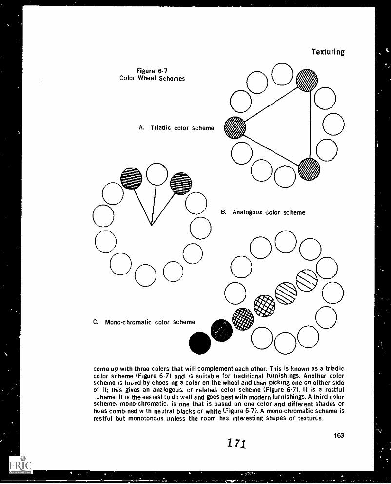
Figure 6-7Color Wheel Schemes
A. Triadic color scheme
Texturing
B. Analogous color scheme
O
C. Mono-chromatic color scheme
come up with three colors that will complement each other. This is known as a triadiccolor scheme (Figure 6-7) and is suitable for traditional furnishings. Another colorscheme is found by choosing a color on the wheel and then picking one on either sideof it; this gives an analogous, or related, color scheme (Figure 6-7). It is a restful...heme. It is the easiest to do well and goes best with modern furnishings. A third colorscheme, mono chromatic, is one that is based on one color and different shades orhues combined with neJtral blacks or white (Figure 6-7). A mono-chromatic scheme isrestful but monotonous unless the room has interesting shapes or textures.
171163
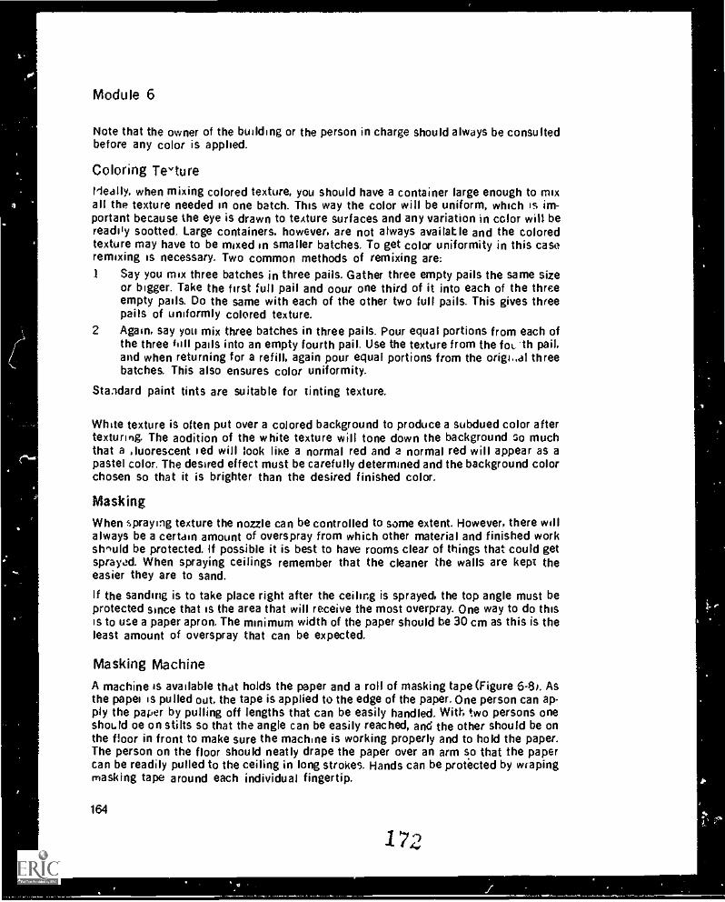
Module 6
Note that the owner of the building or the person in charge should always be consultedbefore any color is applied.
Coloring Tevture
Ideally, when mixing colored texture, you should have a container large enough to mixall the texture needed in one batch. This way the color will be uniform, which is im-portant because the eye is drawn to texture surfaces and any variation in color will bereadily sootted. Large containers, however, are not always available and the coloredtexture may have to be mixed in smaller batches. To get color uniformity in this caseremixing is necessary. Two common methods of remixing are:1 Say you mix three batches in three pails. Gather three empty pails the same size
or bigger. Take the first full pail and oour one third of it into each of the threeempty pails. Do the same with each of the other two full pails. This gives threepails of uniformly colored texture.
2 Again, say you mix three batches in three pails. Pour equal portions from each ofthe three hill pails into an empty fourth pail. Use the texture from the foi., -th pail,and when returning for a refill, again pour equal portions from the origi..al threebatches. This also ensures color uniformity.
Standard paint tints are suitable for tinting texture.
White texture is often put over a colored background to produce a subdued color aftertexturing. The aodition of the white texture will tone down the background 3o muchthat a Atiorescent red will look like a normal red and a normal red will appear as apastel color. The desired effect must be carefully determined and the background colorchosen so that it is brighter than the desired finished color.
Masking
When spraying texture the nozzle can be controlled to some extent. However, there willalways be a certain amount of overspray from which other material and finished workshould be protected. If possible it is best to have rooms clear of things that could getsprayed. When spraying ceilings remember that the cleaner the walls are kept theeasier they are to sand.
If the sanding is to take place right after the ceiling is sprayed, the top angle must beprotected since that is the area that will receive the most overpray. One way to do thisis to use a paper apron. The minimum width of the paper should be 30 cm as this is theleast amount of overspray that can be expected.
Masking Machine
A machine is available that holds the paper and a roll of masking tape (Figure 6-8,. Asthe paper is pulled out. the tape is applied to the edge of the paper. One person can ap-ply the paper by pulling off lengths that can be easily handled. With two persons oneshould oe on stilts so that the angle can be easily reached, and the other should be onthe floor in front to make sure the machine is working properly and to hold the paper.The person on the floor should neatly drape the paper over an arm so that the papercan be readily pulled to the ceiling in long strokes. Hands can be protected by wrapingmasking tape around each individual fingertip.
164
172
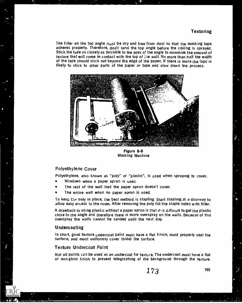
Texturing
The filler on the top angle must be dry and free front dust so that the masking tapeadheres properly. Therefore, don't sand the top angle before the ceiling is sprayed.Stick the tape as close ly as possible to the apex of the angle to minimize the amount oftexture that will come in contact with the top of Zae wall. No more than half the widthof the tape should stick out beyond the edge of the paper; if there is more the tape islikely to stick to other parts of the paper or tape and slow down the process.
1.
4 rd.
70
.aqr Gasendey. .- .701
Figure 6.8Masking Machine
Polyethylene Cover
Polyethylene, also known as "poly" or "plastic", is used when spraying to cover.Windows when a paper apron is used.The rest of the wall that the paper apron doesn't cover.The entire wall when no paper apron is used.
To keep t:-,e poly in place, the best method is stapling. Start stapling at a doorway toallovy easy access to the room. After removing the poly fill the staple holes with filler.
A drawback to using plastic without a paper apron is that it is difficult to get the plasticclose to the angle and therefore there is more overspray on the walls. Because of thisoverspray the walls cannot be sanded until the next day.
Undercoating
In short, good texture undercoat paint must have a flat finish, must properly seal thesurface, and must uniformly cover (hide) the surface.
Texture Undercoat PaintNot all paints can be used as an undercoat for texture. The undercoat must have a flator non-gloss finish to prevent telegraphing of the background through the texture.
173 165
Module 6
Gloss paints are also unsuitable because they do not offer a keyed surface for the tex-ture to adhere to.
The undercoat must seal the surface to prevent "photographing" of the joints. Filler is anatural selling material that does not readily absorb water, whereas paper will absorbwater more quickly. If the paper around the filler is not sealed, the difference in ab-sorption rates causes a difference in the color of the joints. The sealer prevents waterfrom being absorbed by either the paper or the filler. This means that the waterevaporates at the same rate on the surfaces of both. therefore the same color is main-tained.
The paint must also hide joints, that is it must have enough pigment to give the entiresurface the same color. If it does not, the texture will emphasize the transparency ofthe paint and the joints and nails will show through the texture.
When buying undercoating paint, choose one that meets all three criteria. Note thateven an expensive sealer usual!) will not hide well. It is designed to seal the surfacewith a film, and it does this with a high proportion of binder and little pigmentation.Similarly, a good hiding paint will be highly pigmented but low on binder; therefore it isnot a good sealer. Special texture vndercoat paints are on the market and arepreferable to other paints or sealers.
A texture undercoat paint must dry quickly, because the finisher wants to beL.n tex-turing as soon as possible after painting. Latex paints meet this crit6tion because theyare water-based and ;hus evaporate faster than oil-based paints. As a latex paint dries,it forms a film on the surface and dries inward. This film must be formed before tex-turing begins. If the film does not have a chance to completely form, the water in thetexture will dissolve it and the paint will not seal, resulting in photographing of thejoints.
Alkyd paint is becoming increasingly popular at a texture undercoat paint iiecause itdries fast and covers well. Cleanup with alkyd takes longer tnan with latex becausethinner must be used.
The watering-down or thinning of paint is not safe unless recommended by tPmanufacturer. Thinning paint to make it go further actually does the opposite in somecases because the pigment becomes diluted, reducing the hiding power of the paintand thus maki.4 it necessary to use more. Another problem with thinning is that thebinder may be over extended and a good seal will not form. After a thorough mixing.paint should be used as it comes from the can unless otherwise specified. The mixingis necessary to replace material into the emulsion that may have settled to the bottomduring storage.
FeintingA paint brush attached for aided extension to a piece of wood or metal with maskingtape can be used to ''cut in" the corners, th-.t is, paint the edge of the wallboard in theangle where the roller does not quite reach. If this is not done. the angles of the roomwill slit* as discolored areas after texturing has been completed. Aniiles should be WIin before applying the paint by roller.
A long handle should be screwed into the roller handle L peed the process of paintingthe ceiling. The longer the pile on the roller the more paint the roller can hold and the
166
174
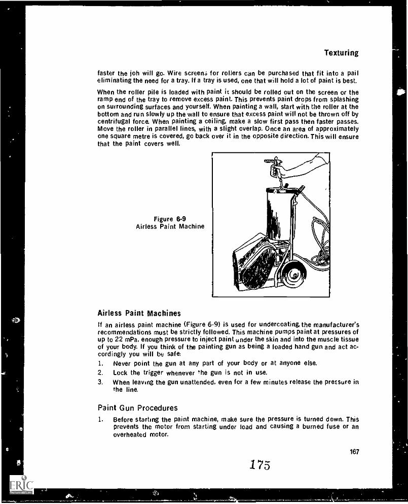
Texturing
faster the job will go. Wire screen.; for rollers can be purchased that fit into a paileliminating the need for a tray. If a tray is used, one that will hold a lot of paint is best.
When the roller pile is loaded with paint h should be rolled out on the screen or theramp end of the tray to remove excess paint. This prevents paint drops from splashingon surrounding surfaces and yourself. When painting a wall, start with the roller at thebottom and run slowly up the wall to ensure that excess paint will not be thrown off bycentrifugal force. When painting a ceiling, make a slow first pass then faster passes.Move the roller in parallel lines, with a slight overlap. Once an area of approximatelyone square metre is covered, go back over it in the opposite direction. This will ensurethat the paint covers well.
Figure 6-9Airless Paint Machine
Airless Paint MachinesIf an airless paint machine (Figure 6-9) is used for undercoating, the manufacturer'srecommendations must be strictly followed. This machine pumps paint at pressures ofup to 22 mPa, enough pressure to inject paint under the skin and into the muscle tissueof your body. If you think of the painting gun as being a loaded hand gun and act ac-cordingly you will be safe:1. Never point the gun at any part of your body or at anyone else.2, Lock the trigger whenever the gun is not in use.3. When leaving the gun unattended. even for a few minutes release the pressure in
the line.
Paint Gun Procedures1. Before starting the paint machine, make sure the pressure is turned down. This
prevents the motor from starting under load and causing a burned fuse or anoverheated motor.
175167
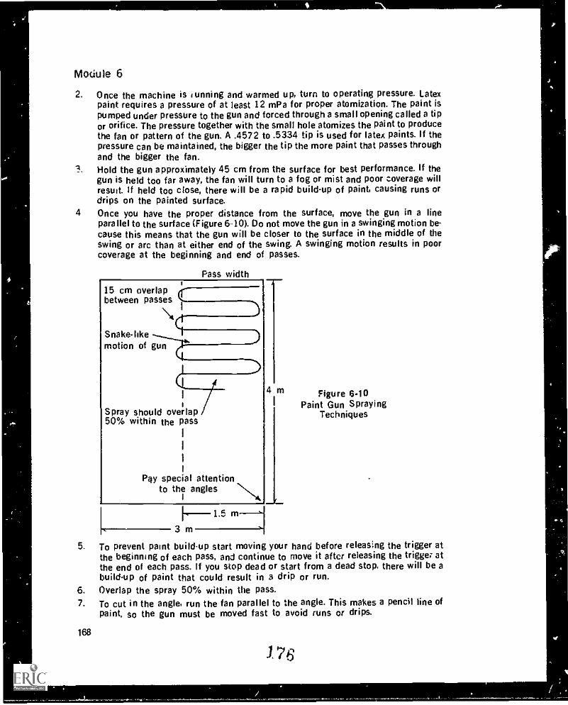
Module 6
2. Once the machine is sunning and warmed up, turn to operating pressure. Latexpaint requires a pressure of at least 12 mPa for proper atomization. The paint ispumped under pressure to the gun and forced through a small opening called a tipor orifice. The pressure together with the small hole atomizes the paint to producethe fan or pattern of the gun. A .4572 to .5334 tip is used for latex paints. If thepressure can be maintained, the bigger the tip the more paint that passes throughand the bigger the fan.Hold the gun approximately 45 cm from the surface for best performance. If thegun is held too far away, the fan will turn to a fog or mist and poor coverage willresult. If held too close, there will be a rapid build-up of paint, causing runs ordrips on the painted surface.
4 Once you have the proper distance from the surface, move the gun in a lineparallel to the surface (Figure 6-10). Do not move the gun in a swinging motion be-cause this means that the gun will be closer to the surface in the middle of theswing or arc than at either end of the swing. A swinging motion results in poorcoverage at the beginning and end of passes.
Pass width
15 cm overlapbetween passespasses
i _..)
Snake-like
\$1
..)motion of gun
4 m
Spray should overlap50% within the pass
Pay special attentionto the angles N
Figure 6.10Paint Gun Spraying
Techniques
---1.5 m3 m
5. To prevent paint build-up start moving your hand before releasing the trigger atthe beginning of each pass, and continue to move it after releasing the trigger atthe end of each pass. If you stop dead or start from a dead stop, there will be abuild-up of paint that could result in a drip or run.
6. Overlap the spray 50% within the pass.7. To cut in the angle, run the fan parallel to the angle. This makes a pencil line of
paint, so the gun must be moved fast to avoid runs or drips.
168
176
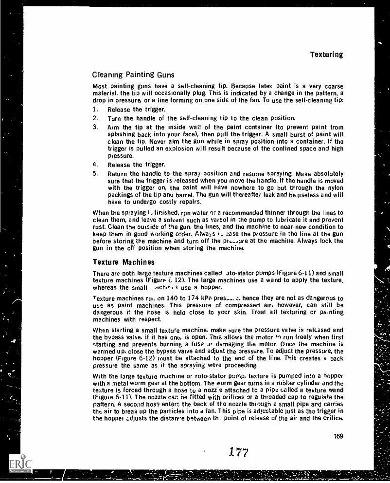
Texturing
Cleaning Painting GunsMost painting guns have a self-cleaning tip. Because latex paint is a very coarsematerial, the tip will occasionally plug. This is indicated by a change in the pattern, adrop in pressure, or a line forming on one side of the fan. To use the self-cleaning tip:1. Release the trigger.2. Turn the handle of the self-cleaning tip to the clean position.3. Aim the tip at the inside waif of the paint container (to prevent paint from
splashing back into your face), then pull the trigger. A small burst of paint willclean the tip. Never aim the gun while in spray position into a container. If thetrigger is pulled an explosion will result because of the confined space and highpressure.
4. Release the trigger.5. Return the handle to the spray position and resume spraying. Make absolutely
sure that the trigger is released when you move the handle. If the handle is movedwith the trigger on, the paint will have nowhere to go but through the nylonpackings of the tip anu barrel. The gun will thereafter leak and be useless and willhave to undergo costly repairs.
When the spraying i .. finished, run water 'r a recommended thinner through the lines toclean them, and leave a solvent such as varsol in the pump to lubricate it and preventrust. Clean the outside of the gun, the lines, and the machine to near-new condition tokeep them in good working order. Alwa s to ease the pressure in the line at the gunbefore storing We machine and turn off the pr,.-...ure at the machine. Always lock thegun in the off position when storing the machine.
Texture MachinesThere are both large texture machines called ato-stator pumps (Figure 6-11) and smalltexture machines (Figure f, 12). The large machines use a wand to apply the texture,whereas the small idchir 4_3 use a hopper.
Texture machines rut. on 140 to 174 kPa Ares..... s, hence they are not as dangerous touse as paint machines. This pressure of compressed air, however, can still bedangerous if the hose is held close to your skin. Treat all texturing or pantingmachines with respect.
When starting a small texture machine, make pure the pressure valve is released andthe bypass valve, if it has one, is open. This allows the motor +1 run freely when firststarting and prevents burning a fuse ar damaging the motor. Once the machine iswarmed up, close the bypass valve and adjust the pressure. To adjust the pressure, thehopper (Figure 6-12) must be attached to the end of the line. Tills creates a backpressure the same as if the spraying were proceeding.
With the large texture machine or roto-stator pump, texture is pumped into a hopperwith a metal worm gear at the bottom. The worm gear turns in a rubber cylinder and thetexture is forced through a hose to a nozie attached to a pipe called a texture wand(Figure 6-11). The nozzle can be fitted with orifices or a threaded cap to regulate thepattern. A second hose enterc the back of De nozzle thi °ugh a small pipe and carriesthe air to break up the particles into d fan. This pipe is adjustable just as the trigger inthe hopper z.djusts the distance between th . point of release of the air and the orifice.
169
177
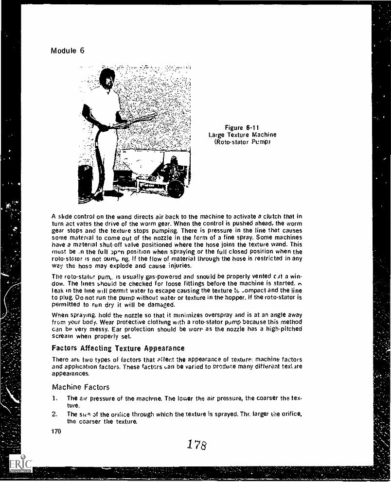
Module 6
Figure 6-11Large Texture Machine
(Roto-stator Pump)
A slide control on the wand directs air back to the machine to activate a clutch that inturn act vates the drive of the worm gear. When the control is pushed ahead, the wormgear stops and the texture stops pumping. There is pressure in the line that causessome material to come out of the nozzle in the form of a fine spray. Some machineshave a material shut-off valve positioned where the hose joins the texture wand. Thismust be .n the full pro position when spraying or the full closed position when theroto-sWtor is not °um', ng. If the flow of material through the hose is restricted in anyway the hose may explode and cause injuries.
The roto-stator pum,. is usually gas-powered and snou Id be properly vented c.it a win-dow. The lines should be checked for loose fittings before the machine is started.leak in the line will permit water to escape causing the texture ti.....ompact and the lineto plug. Do not run the pump without water or texture in the hopper. if the roto-stator ispermitted to run dry it will be damaged.When spraying hold the nozzle so that it minimizes overspray and is at an angle awayfrom your body. Wear protective clothing with a rotostator pump because this methodcan be very messy. Ear protection should be worn as the nozzle has a high-pitchedscream when properly set.
Factors Affecting Texture AppearanceThere are two types of factors that affect the appearance of texture: machine factorsand application factors. These factors t. an be varied to pso-duce many different text ireappearances.
Machine Factors1. The air pressure of the machine. The lower the air pressure, the coarser the tex-
ture.
2. The 5141 of the orifice through which the texture is sprayed. Thr. larger the orifice,the coarser the texture.
17&
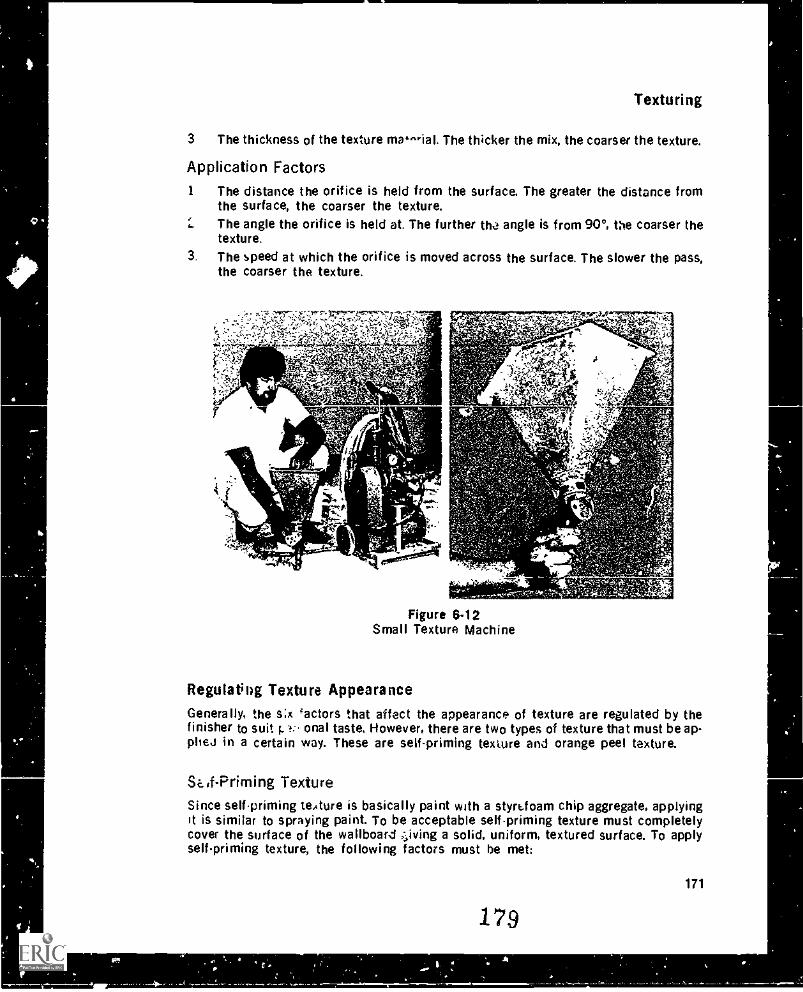
Texturing
3 The thickness of the texture matial. The thicker the mix, the coarser the texture.
Application Factors1 The distance the orifice is held from the surface. The greater the distance from
the surface, the coarser the texture.The angle the orifice is held at. The further tha angle is from 90°, the coarser thetexture.
3. The speed at which the orifice is moved across the surface. The slower the pass,the coarser the texture.
w
,SZnA
11.4
:% 4'4'44
're'Otr -*AS 1'
Figure 6.12Small Texture Machine
-
Regulating Texture Appearance
Generally, the s:x 'actors that affect the appearance of texture are regulated by thefinisher to suit 1.1.- anal taste. However, there are two types of texture that must be ap-plieJ in a certain way. These are self-priming texture and orange peel texture.
Si.if-Priming TextureSince selfpriming texture is basically paint with a styrk.foam chip aggregate, applyingit is similar to spraying paint. To be acceptable self-priming texture must completelycover the surface of the wallboard ,riving a solid, uniform, textured surface. To applyselfpriming texture, the following factors must be met:
171
179
0
Module 6
Machine Factors:1. High air pressure.2. The second smallest orifice.3. A thin mix.
Application Factors:1. An orifice to surface distance of approximately 45 cm.2. A 45° spraying angle.3. A medium to fast speed that covers but does not overload.
Orange Peel Texture
Orange peel texture should completely cover the surface of the wallboard with smallpinholes like the surface of an orange peel. Too much texture material causes thepinholes to disappear and the texture to drip or run. Too little material and the surfacewill not be covered leaving an anemic looking texture. To proauce an orange peel tex-tured surface, the following factors must be mPt:
Machine Factors:1. High air pressure.2. The smallest orifice.3. A thin mix.
Application Factors:1. An orifice to surface distance of approximately 302. A spraying angle close to 90°.3. A slow speed to ensure total coverage.
Cm.
Texture Spraying TechniquesFollowing are general texture spraying techniques that apply for all textures:1. Eye protection and a mask are required when using a texture machine.2. Passes are made along the length of the surface. Since the passes are 1.5 m to 2
m in width, most surfaces can be done in 2 passes.3. Spread your feet approximately 60 cm apart a ,c1 shuffle backwards at a rate that
gives proper coverage of the surface.4. The wand or hopper must move in a snakelike motion back and forth across the
width of the pass (Figure 6-13). To accomplish this motion the arm is eld rigidwhile the body is rocked from side to side. The wrists should Only move ai tile endof each pass. giving a flick as the wand or hopper is turned back t e other way.
5. The wand or hopper should move in straight. no wiggly, lines across the width ofthe pass.
6. The spray overlap as the wand or hopper is moved back and forth across the widthof the pass should be approximately 50%.
7. The distance of the orifice to the surface should be constant.8. The spraying angle should be constant.9. The speed at which the wand or hopper moves should be constant.
172
180
Pass width
Overlap betweenpasses:
15 cm for sell-
and soft textureqpriming texture
Virtually nonefor hard texture
Snake-like motionof wand or hopper.
Overlap of spray withinI the pass:
50% for self-primingtextures
4 50% or less for hardand soft texturesdepending on the
4 m desired thickness
m
3 m
Texturing
Figure 6-13Texture Spraying Techniques
Soft Texture On Flat Ceilings1. Spray the angles and all around the edges.2. Make passes down the length of the ceiling.3. The passes can be made in either direction.4. Slightly overlap the spray where the passes join.
Hard, Splatter Texture On Flat r;eilings1. The angles and edges are not pre-sprayed as is done with soft texture.2. Make all passes in the same direction.3. Do not overlap at the ;oint of the passes.
Ceilings With Drops1. Spray the drop first.2. Spray the exterior angle of the drop, bisecting the angle with the spray (Figure C-
14).
3. Spray the interior angle of the drop, again bisecting the angle with the spray.4. Spray the remaining area of the drop.
The reason for this sequence is that if you did the main surface of the drop first and theangles last, you would get a build up on the main surface from the angle overspray andthus the texture would be inconsistent.
181
0
Module 6
2. Angle sprayed
3. This area sprayedlast
1. Texture must bedirected at theexterior anglefirst
Figure 6.14Texturing a Drop
Walls
Single. flat walls are done similarly to hard texture on a flat ceiling if the wall(s) hasinterior and exterior angles, they should be dooe first as is described for ceiling drops.
A texture pattern cane,' 3 knock down texture is used on walls. A knock down texture i;one that is applied by machine then "knocked down" with a trowel. California texture isa common knock down texture pattern. To get the bps. results when knock (town tex-turing walls, it is necessary to spray the walls twice.1 he first spraying will give the walla fog coat. The texture mix for this coat should be thin, be applied at a high pressuresetting on the machine (140 to 200 kPa), and be sprayed through a small orifice. Thefog coat will provide a base fog the second coat, which should be slightly thicker and besprayed at a iow pressure through a big orifice. The further the nozzle is hrsd from thewall the bigger are the blobs of spray that hit the wall, since the texture will have achance to flatten out before it hits. Before trowelling. wait until the texture looses itsshine and takes on a dull appearance. Trowelling too soon will cause the texture tospread out too much; too late and the texture will roll and come off the wall with thetrowel.
Spraying Over Colored BackgroundsWhen spraying over a colored background. watch the pattern of the spray to ensure thatit does not bunch up in one area nor is too lean in another. Because the white texturecontrasts with the colored background, imperfections in the spray pattern are easilyseen. This also holds for colored texture applied to a white background.
Finishing Off Ceilings After TexturingAfter the ceiling is textured the protective paper apron must be removed. This shouIdbe done as soon as possible after texturing. If left too long the texture will start to dryand adhere to the paper apron. Then, when the apron is removed, it will tear off texture
182
Texturing
from the ceiling. After the apron is removed the angles should be cut in and c,eaned. Awide blade knife is run al...ng the angle to form a definite line between the wall andceiling. At the same time, any overspray at the top of the wall should be cleaned. Thismakes the ceiling look finished and makes it easier for the painter to ci..t in the anglewhen the wall is painted. Care must be taken when cutting in and cleaning the angle sothat the filler on the angle is not gouged out.
Any overspray on the walls that the paper apron didn't catch should be scraped with aknife. A 45 to 60 cm knife is desirable because it can cover a lot of wall surface in ashort time. The knife should be cleaned regularly while scraping to prevent a build-upof texture that smears the wall.
Hand TexturingHand application of texture enables the finisher to display artistic talents. But keepthese two concerns in mind. high traffic areas should not have soft texture because itwill be damaged by abrasion; icicle-type texture finishes should be used only onceilings where there is no danger of the sharp spikes causing puncture wounds. Withhand applied texture, surface preparation need not be as thorough at for machine ap-plied texture.
Hand finishes can be divided into three basic types: built-up textures, one-coatfinishes, and stipple patterns. Built-up textures require two coats of texture: a basecoat, which must dry, then a second coat which is worked into a pattern. For one-coatfinishes, the texture is trowelled on to the wall or ceiling and is then textured with asponge, brush, or paper. Stipple patterns are applied direct with a texture applicator. Atno time should the thickness of a coat of texture exceed 5 mm, otherwise cracking willoccur.
Start in the cornerof the ceiling
Figure 6.15Built-up Texture Pattern
Built-Up TexturesA base coat of texture materials is applied to a wall or a ceiling with a trowel. This coatshould t i smooth and no thicker than 5 nm. Once thP base coat is dry, a second coat is
183 175
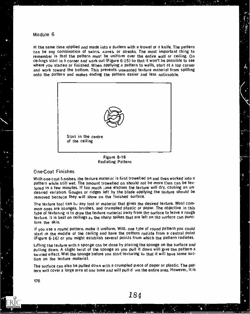
Module 6
at the same time applied and made into a pattern with a trowel or a knife. The patterncan be any combination of swirls, waves, or streaks. The most important thing toremember is that the pattern must be uniform over the entire wall or ceiling. Onceilings start in a corner and work out (Figure 6-15) so that it won't be possible to seewhere you started or finished. When applying a pattern to walls, start at a top cornerand work toward the bottom. This prevents unwanted texture material from spillingonto the pattern and makes ending the pattern easier and less noticeable,
Start in the centreof the ceiling
Figure 6.16Radiating Pattern
One-Coat FinishesWith one-coat finishes, the texture materia! is first trowelled on and then worked into apattern while still wet. The amount trowelled on should not be more than can be tex-tured in a few minutes. If too much *time elapses the texture will dry, causing an un-desired variation. Gouges or ridges left by the blade applying the texture should beremoved because they will show on the finished surface.
The texture tool can b4 any tool or material that gives the desired texture. Most com-mon ones are sponges, brushes, and crumpled plastic or paper. The objective in thistype of texturing is to draw the texture material away from the surface to leave a roughtexture. It is best on ceilings as the sharp spikes that are left on the surface can punc-ture the skin.If you use a round pattern, make it uniform, Wit li one type of round pattern you couldstart in the middle of the ceiling and have the pattern radiate from a central point(Figure 6-16) or you might establish several points from which the pattern radiates.
Lifting the texture with a sponge can be done by placing the sponge on the surface andpulling down. A slight twist of the sponge as you pull it down will give the pattern aswirled effect. Wet the sponge before you start texturing su that it will have some suc-tion on the texture material.The surface can also be pulled down with a crumpled piece of paper or plastic. The pat-tern will cover a large area at one time and will pull d wn the entire area. However, it is
176
184
Texturing
difficult to keep the texture uniform with this method.
Brooming or brushing of the material gives a rustic effect. Straight lines or swirls caneasily be accomplished. The timing between the trowelling of the texture and thebrooming will regulate the roughness of the texture: the longer the time, the smootherthe texture.
Stipple PatternsAnother type of hand texturing is done by applying the texture direct to the surfacewith a texture applicator commonly :ailed a stipple pad. Window-washing brushes dip-ped in a thin mix will produce a sharp, rippled effect that can either be left as is ortrowelled to flatten the peaks. Stipple pads (foam rubber covered with a piece of cloth)ranging from 3 cm to 8 cm in diameter will produce ar; icicle effect. To lengthen theicicles, add latex paint to the mix and use a mix that is about as thick as a second-coatbead filler. The addition of fine perlite will reduce cracking. By varying the thicknessand the amount of paint, you will find the desired icicle length. Pour the mix into asmall pail that ...an be held comfortably under your arm. Dip the stipple pad into themix and then dab it onto the surface. An undercoat of flat white paint on the surtacebefore stipoing will help reduca bare specs in the over-all pattern.
SUMMARY
There are three basic textures: hard, soft and self-priming.Hard textures are mainly used on walls.Soft and self-priming textures are used only on ceilings.StIf priming and hard textures can be used in bathrooms and kitchens but softtextures cannot.Walk in high traffic areas must have smooth textuies.Glitters of many ' ^os and colors can be blown on wet texture.Draw reterenc lines prior to laying o. ceiling designs.Stondard color tints are used to Uri texturesColc-en texture mixed in small batches must be remixed to ensure uniformity ofcolorUse a color wheel to aid i.. selecting col-Dark colors appear to close in areas.Light colors appear to expand a _.isColored texture will dry one ohaoe lighter than it app 'fan when wet.All textures except self-priming equire an undercoat.Use A good quality te,:t, ,:: undercoat paint.Seal dirt or chalk line marks before undercoating.
4 Follow the corm, procedures for using a paint gun and for cleaning a gun.Texture will not cover ridgee or scratches.Top angles must be masked off with either plastic or paper to prevent ceiling over-spray from hitting tne walls. Rem-we the paper or plastic soon after the ceiling issprayed.
.1 85
177
Module 6
The two types of factors affecting texture appearance are machine factors and ap-plication factors.Self-priming texture and orange peel texture require specific machine settingsand spraying techniques: other text' res do not.Use the correct techniques and sequences when spraying.
EXERCISE
1. What are the three types of texture and where is each used?2. When is glitter applied?3. Trut. or False? A surface that is to be hard textured requires less preparation than
a surface that will be painted with flat latex.4. Why do you need to establish reference lines when painting a design on a ceiling
or wall?5. What is the difference between warm and cool colors?6. How can you avoid different shades of color when applying colored texture?7. Why is it not a good idea to sand the walls before texturing the ceilings?8. how much tape should extend beyond the edge of the paper apron?9. What is the best method of hanging poly?
10. What are the three characteristics of a good texture undercoat paint?11. Why should you not thin down a texture undercoat paint?12. What does "cutting in" mean when painting?13. What are three main safety procedures when using an airless painting gun?14. How do you prevent paint build-up at the beginning and encil of passes?15. Why must you release the tr.gger of the paint gun before turning the handle on
self-cleaning tips?16. List tae three machine factors and the three application factors that affect texture
appearance
17. True or False? The arm is held rigid when spraying texture?18. When is a texture ready to trowel for a knock down finish?19. What must you watch for when spraying over a colored background?20. How do you cut in a ceiling after it is textured?21. What are the three basic hand finishes for texture?24. What s the maximum thickness of a coat of texture for hand texturing?
in 186
Repairs andCorrections
MODULE 7
INTRODUCTION
The finisher produces a product that is on display and open to criticism. Problems candevelop both during the finishing process and after the job is completed and thebuilding occupied. This module outlines the types of repairs finishers are called on tomake.
Repairing Gouges, Ridges and Other Defects As You GoRepair gouges while the filler is still wet because it saves time. if you let a gouge dry, itwill require either three coats of slow-set. or one coat of fast-set plus one of slow-set torepair. Repairing while the filler is still wet allows the filled gouge to shrink at the samerate as the filler around it, leaving no noticeable affect.
Usually. by the time vou get to a gouge on wet filler a film or -Ain has formed on top ofthe filler_ When a blade is run over this film, it causes a tearing of the surface known asa "pull". This occurs usually because you think it is possible to fill in the gouge bydrawing the filler already on the wall onto the defective area. The solution is to fill thegouge with fresh filler from your pan or hawk. By putting fresh filler across the width ofthe blade you will not pull the filler surrounding the defect.
Why does his method prevent pull? The addition of fresh. moist filler softens the filmthat has developed on 'he surface of the fill. The filler then becomes thixotropic oncemore.
Repair ridges as soon as possible after applying the filler. Remove the ridge by runningthe blade parallel to it (Figure 7-1). Most blades have a slight bow in them; us : thebowed out side toward the filler so that the ends of the blade doril dig into the filler.Apply enough pressure so that there is evidence of the knife touching the filler oneither side of the ridge. You do not have to put filer on the knife to correct a ridge be-cause the ridge is already too high. If a film has already formed on the filler, lubricatethe blade with water. This will soften the film and prevent pulling.ii '4 ridge is missed whet wet and has to t e sanded out, sand down the ridge not acrossit if you try to sand across a ridge, you usually succeed only .n removing part of it. Asshown in Figure 7-2, the sander follows the contour of the ridge, grinding out the',alleys and knocking the top off the ridge. At first glance it appears that the ridge isremoved, but 1, reality it is not. Further filling over this area will not imprive the sur-face because the blade follows the contour of the surface. By sanding down the ridgethe sander o..I) contacts the ridge and does not grind out valleys on either side. Itshould be point..o out, however. Oat sanding a ridge is never totally satisfactory andthat it is far better ' take out the ridge when it is wet.
187179
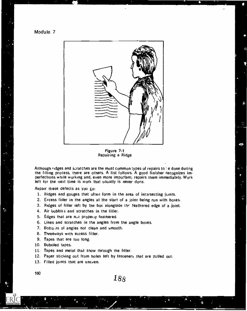
Module 7
Figure 7-1Repairing a Ridge
Although ridges and scratches are the most common types of repairs to : e done duringthe filling process, there are others. A list follows. A good finisher recognizes im-perfections while working and, even more important, repairs them immediately. Workleft for the next time is work that usually is never done.
Repair these defects as you 0:1. Ridges and gouges that often form in the area of intarsecting joints.2. Excess filler in the angles at the start of a joint being run with boxes.3. Ridges of filler ieft by the box alongside th' feathsred edge of a joint.4. Air bubbles and scratches in the filler.5. Edges that are rivt properiy feathered.6. Lines and scratches in the angles from the angle boxes.7. Botto.as of angles not clean and smooth.8. Threeways with excess filler.9. Tapes that are too long.
10. Bubofed tapes.11. Tapes and metal that show through the filler.12. Paper sticking out from holes left by fasteners that are pulled out.13. Filled joints that are uneven.
180
188
r
0
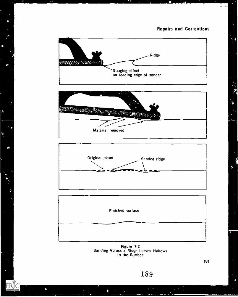
Repairs and Corrections
;,:-.,1:::.:.._.7.,:'.,.:::,=:,;:$7..,,,....:..:..,..--
Ridge
Gouging effecton leading edge of sander
--i'I"..,-------Material removed
Original plane Sanded ridge
----ft - -L_L=_:_..-r- ..-:- -\,..._
Finished surface
.mmm.mm..m.a. ..=1.,...,
Figure 7-2Sanding Across a Ridge Leaves Hollows
in the Surface
189
181
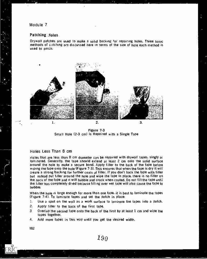
Module 7
Patching :soles
Drywall patches are used to make a solid backing for repairing holes. Three basicmethods of p.-itching are discussed here in terms of the size of hole each method isused to patch.
2.
Figure 7-3Small Hole (2-3 cm) is Repaired with a Single Tape
Holes Less Than 8 cmHoles that are less than 8 cm diameter can be repaired with drywall tapes, singly orlaminated. Generally, the tape should extend at least 2 cm onto the solid surfacearound the hole to make a secure bond. Apply filler to the back of the tape beforewiping the tape onto the hole (Figure 7-3). This ensures that when the tape is dry it willcreate a strong backing for further coats of filler. If you don't back the tape with fillerbut nstead put filler around the hole and wipe the tape in place. there is no filler onthe oack of the tape and it will bubble and crack when coated. Do not fill the tape untilthe filler has completely dried because filling over wet tape will also cause the tape tobubble.
When the hole is large enough for more than one tape, it is best to laminate the tapes(Figure 7.4). To laminate tapes and set the patch in place:1. Use a spot on the wall as a work surface to laminate the tapes into a patch.2. Apply filler to the back of the first tape.3 Overlap the second tape onto the back of the first by at least 1 cm and wipe the
tapes together.4. Add more tapes in this way until you get the desired width.
190
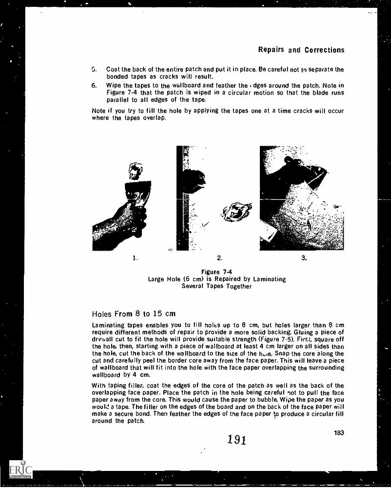
Repairs and Corrections
5. Coat the back of the entire patch and put it in place. Be careful not to separate thebonded tapes as cracks will result.
6. Wipe the tapes to the wallboard and feather the dges around the patch. Note inFigure 7-4 that the patch is wiped in a circular motion so that the blade runsparallel to all edges of the tape.
Note if you try to fill the hole by applying the tapes one at a time cracks will occurwhere the tapes overlap.
1. 2.
"-
.3v
Figure 7-4Large Hole (6 cm) is Repaired by Laminating
Several Tapes Together
3.
Holes From 8 to 15 cmLaminating tapes enables you to fill holes up to 8 cm, but holes larger than 8 cmrequire different methods of repair to provide a more solid backing. Gluing a piece ofdrvv411 cut to fit the hole will provide suitable strength (Figure 7-5). First, square offthe hole, then, starting with a piece of wallboard at least 4 cm larger on all sides thanthe hole, cut the back of the wallboard to the size of the hoe. Snap the core along thecut and carefully peel the border core away from the face paper. This will leave a pieceof wallboard that will fit into the hole with the face paper overlapping the surroundingwallboard by 4 cm.
With taping filler, coat the edges of the core of the patch as well as the back of theoverlapping face paper. Place the patch in the hole being careful not to pull the facepaper away from the core. This would cause the paper to bubble. Wipe the paper as youwould a tape. The filler on the edges of the board and on the back of the face paper willmake a secure bond. Then feather the edges of the face paper c-.1 produce a circular fillaround the patch.
191183
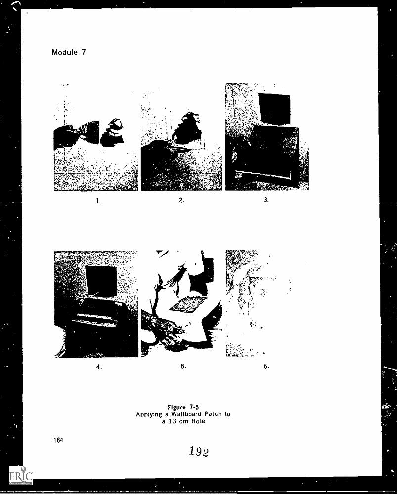
Figure 7-5Applying a Wallboard Patch to
a 13 cm Hole
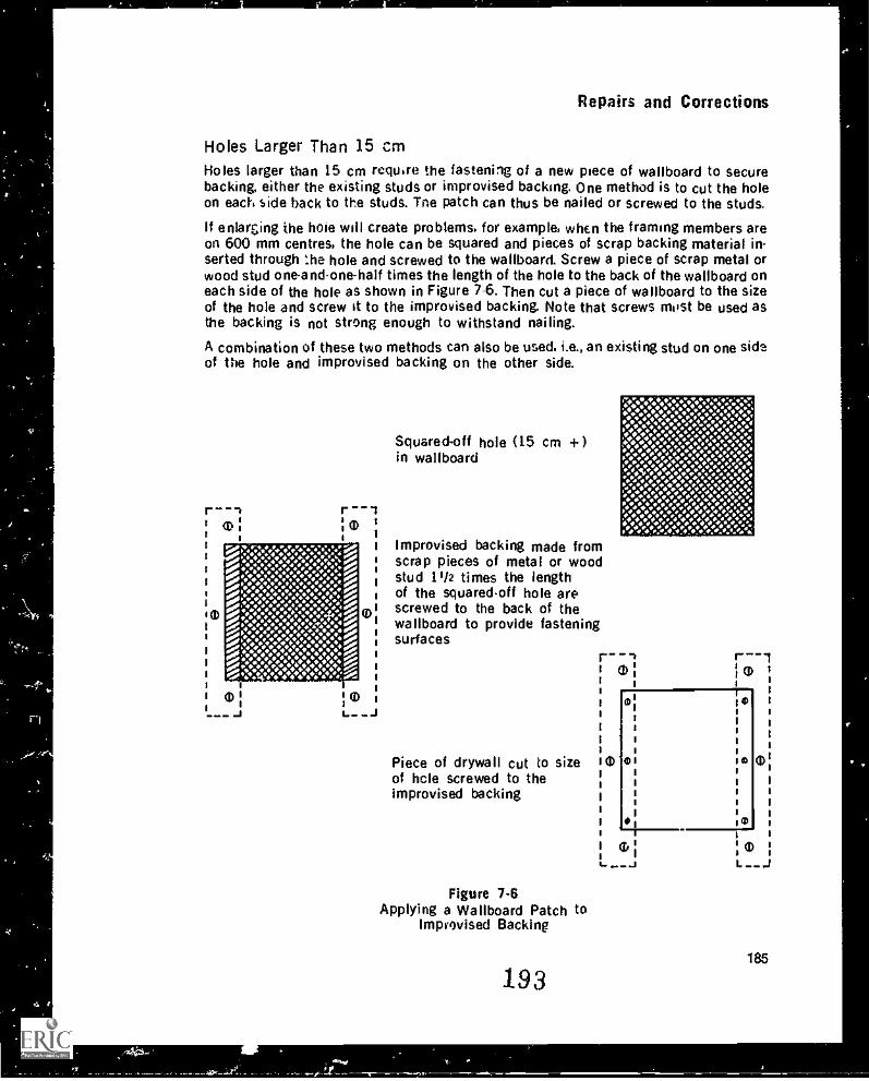
Repairs and Corrections
Holes Larger Than 15 cmHoles larger than 15 cm require the fastening of a new piece of wallboard to securebacking, either the existing studs or improvised backing. One method is to cut the holeon each side hack to the studs. Tne patch can thus be nailed or screwed to the studs.
enlarzing the hole will create problems, for example, when the framing members areon 600 mm centres, the hole can be squared and pieces of scrap backing material in-serted through the hole and screwed to the wallboard. Screw a piece of scrap metal orwood stud one-andone-half times the length of the hole to the back of the wallboard oneach side of the hole as shown in Figure 7-6. Then cut a piece of wallboard to the sizeof the hole and screw it to the improvised backing. Note that screws most be used asthe backing is not strong enough to withstand nailing.
A combination of these two methods can also be used. i.e., an existing stud on one sideof the hole and improvised backing on the other side.
em
Squared-off hole (15 cm +in wallboard
r --111)
1
Improvised backing made fromscrap pieces of metal or woodstud 02 times the lengthof the squaredoff hole arescrewed to the back of the®wallboard to provide fasteningsurfaces
Piece of drywall cut to sizeof hole screwed to theimprovised backing
Figure 7-6Applying a Wallboard Patch to
Improvised Backing
193
1 0
(I)
185
Module 7
Holes should be patched according to their size. Trying to fill a large hole with tapesnot only will be difficult but also will not give the necessary strength. Using awallboard patch for a small hole is not practical, it may be stronger. but the time takento properly cut it will not be efficiently spent.
Keying Painted SurfacesFillers must have a rough surface to which to bond. Wallboard with its woven paper sur-face meets this requirement, but painted surfaces encountered when making repairs donot. Painted surfaces, even those with a flat or dull finish, are too smooth for goodadhesion or bonding of the filler. If filler is placed on such a surface the filler will dryand bond internally, but it will not bond well to the painted surface.
Roughing up a surface is known as keying and can be done in two ih ys. mechanical andchemical. Mechanical keying is scoring or scratching the surface. If properly done, thesurface will have a dull look. The most comma! method of keying fairly clean paintedsurfaces is to sand the paint with coarse-grit paper. Paint is very hard on - dry, thus itis unlikely that you will be able to sand through the paint to the wallboard below. Aslong as the surface is not shiny and there are sanding scratches in the paint, you willget a bond with the filler. If sandpaper is not handy, scratching of the surface in a closecrisscross pattern will give the same effect. Be careful though not to cut the surface ofthe wallboard when doing this as it will cause cracking in the finish. The wall should bedusted clean before the CI ling begins.
Chemical treatment of painted wallboard will also produce a keyed surface with goodbonding ability. Tri-sodium phosphate (TSP) is available at any paint store in a crystalform. It is a caustic solution once mixed with water, and therefore Your eyes and skinshould be protected from it. TSP can be applied with a sponge mop over a large surfaceand rinsed off according to instructions on the container. If it is not rinsed off, theresidue of the TSP may react with the filler creating a chemical reaction that destroysthe bond of the filler. When used properly. the surface will turn dull and lose its shine.It is best to allow the wall to dry after the rinse so that the binder in the filler is notdiluted on contact with the wall. Dilution of the binder may cause a poor bond
Chemical keying of a wall is best when the surface to be repaired is in a building thathas been occupied for more than six months. Residues from cookir.b. smoking, or con-tact with oils or greases may have built-up particularly in kitchens, dining rooms, andareas that come in contact with hands. These surfaces 'hould all be keyed chemically.Sanding will scuff the surface and leave it rough. but g ease or oil residues will not berubbed off and a poor bond will result.
Repairing Previously Finished WallboardUsually, you are directed to specific areas for repair on the previously finishedwallboard. These may include hollow areas around fasteners and beads, ridged ,oints,nail pops, gouges in the wall, and cracks. You may also be called on to repair water c:fire damaged wallboard.
Hollow AreasHollow areas are caused by filler shrinking. Shrunken filler results from movement ofthe framing members, or delayed shrinkage in the framing. Both a(e caused by ex-cessive moisture in the building at the time of taping and filling. It is best to wait at
186
194
Repairs and Corrections
least six month.: to a year to repair hollow.; so that the shrinking process is complete.
To repair hollows the surface need only be keyed and three :oats of filler applied thesame as for filling new wallboard. It will be Impossible to apply the first coat of fulerwithout tiny air bubbles appearing in the surface of the filler. Because the wallboardsurface is sealed by the paint, most of the moisture cannot enter the wallboard duringthe drying process and must escape through the surface of the filler, thos creatingpinholes. The second and third coats will fill in the pinholes. You can expect a longerdrying time between coats. Make sure that filling is done on keyed surfaces.
Ridged Joints
Ridged joints can be a result of four causes. If the moisture content of the area you arefilling is high, the filler in the centre of a joint will not dry properly and will decomposeafter 72 hours. This leaves the tape loose in the centre. As successive coats are ap-plied, the tape lifts and causes a ridge. If gaps in joints were not pre-filled the tape willnot be bonded to a solid surface and will ridge when coated. Another cause is if theboard was applied to wet framing members, the members will shrink as the buildingsettles. forcing the boards together and the tape out. It is also possible that the edge ofthe board was damaged in handling or in manufacture leaving loose paper that ridgeswhen coated.
A ridge should be c..ecked with the handle of 3 knife for loose material before repairingit. Run the handle of the knife down the ridge, and if the knife does not leave a troughthen the backing is solid. It is only necessary to key the surface and refill the joint aswith a butt joint. If the knife leaves a trough, the tape is loose and must be cut out andfilled with fast-set before retaping. Retaping the joint without removing the ridged tapewill not solve the problem because there is no solid mater;a1 behind.
Nail Pops, Loose Filler, GougesNail pops are usually t: used by shrinkage of wood studs. As the wood shrinks, it pullsaway from the back of the wallboard and leaves a gap of up to 3 mm. When the wall ismoved by pressure on it, or by vibration, the fastener is forced through the wallboard.Other causes of nail pops aie soft studs, the wallboard was not pushed tight to thestuds when fastened. and the fastener had poor holding power. To repair nail pops. sim-ply push the wallboard tight to the framing member, tighten the fastener or apply a newone, and refill.
Similar in appec.auce to nail pops. loose filler or filler fallen away from the fastener iscaused by the wood being toa dry when the wallboard is installed. Normal moisturecontent is 8 to 14 per cent. As wooa takes on moisture it expands, applying pressure tothe back of the wallboard and forcing it away from the fastener. In such cases, the fillerloosens or falls off the head of she fastener and looks very much like a nail pop. ThereIS no point in tightening the fastener because the head may have been pulled throughthe suiface paper and have lost its holding power. A new fastener should be placedwithin 5 cm of the defective one and bath fasteners filled.
Gouges are a common repair item. If the paper has not been torn or bruised, fill thegouge with three coats of filler. It is important to fill only the gouge as the surroundingwall is probably flat. Scrape each coat Cush with the surrounding surface. On the otherhand, if tf.e gaup is deeper than the surface paper on the wallboard, key the surface,tape the gouge and fill ,t. if the paper is bruised cut out the loose paper and tape andfill the exposed core.
195 187
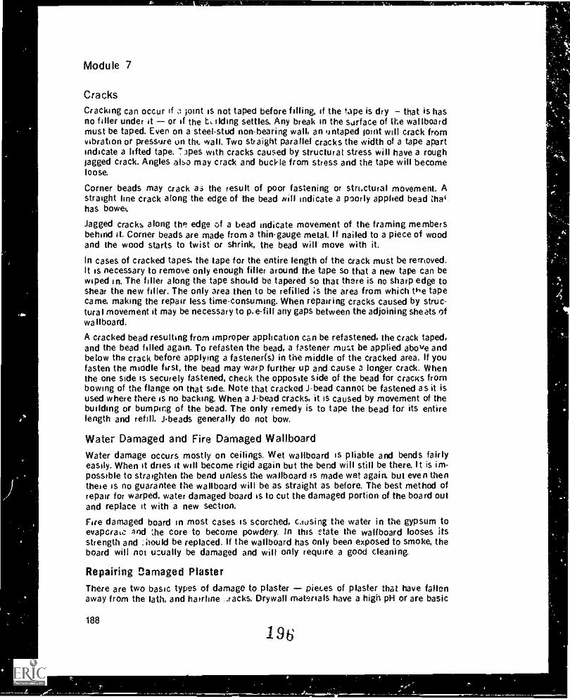
ro,
Module 7
Cracks
Cracking can occur if 3 joint is not taped before filling, if the tape is dry that is hasno filler under it or if the L.ilding settles. Any break in the surface of the wallboardmust be taped. Even on a steel-stud non-bearing wall, an untaped Joint will crack (tornvibration or pressure on thc wall. Two straight parallel cracks the width of a tape apartindicate a lifted tape. 'apes with cracks caused by structural stress will have a roughtagged crack. Angles also may crack and buckle from stress and the tape will becomeloose.
Corner beads may crack as the result of poor fastening or structural movement. Astraight line crack along the edge of the bead Rill indicate a poorly applied bead thathas bowel.
Jagged cracks along the edge of a bead indicate movement of the framing membersbehind it. Corner beads are made from a thin-gauge metal. If nailed to a piece of woodand the wood starts to twist or shrink, the bead will move with it.
In cases of cracked tapes. the tape for the entire length of the crack must be removed.It is necessary to remove only enough filler around the tape so that a new tape can bewiped In. The filler along the tape should be tapered so that there is no sharp edge toshear the new filler. The only area then to be refilled ;s the area from which the tapecame, making the repair less time-consuming. When repairing cracks caused by struc-tural movement it may be necessary to any gaps between the adjoining sheets ofwa Ilboard.
A cracked bead resulting from improper application can be refastened, the crack taped.and the bead filled again. To refasten the bead. a fastener court be applied above andbelow the crack before applying a fastener(s) in the middle of the cracked area. If youfasten the middle first, the bead may warp further up and cause a longer crack. Whenthe one side is securely fastened, check the opposite side of the bead for cracks frombowing of the flange on that side. Note that cracked Jbead cannot be fastened as it isused where there is no backing. When a J-bead cracks, it is caused by movement of thebuilding or bumping of the bead. The only remedy is to tape the bead for its entirelength and refill. Jbeads generally do not bow.
Water Damaged and Fire Damaged WallboardWater damage occurs mostly on ceilings. Wet wallboard is pliable and bends fairlyeasily. When it dries it will become rigid again but the bend will still be there. It is im-possible to straighten the bend unless the wallboard is made wet again, but even thenthese Is no guarantee the wallboard will be as straight as before. The best method ofrepair for warped, water damaged board is to cut the damaged portion of the board outand replace it with a new section.
Fire damaged board in most cases is scorched, causing the water in the gypsum toevaperatc. and he core to become powdery. In this Mate the wallboard looses itsstrength and :iiould be replaced. If the wallboard has Only been exposed to smoke, theboard will not u :ually be damaged and will only require a good cleaning.
Repairing Damaged PlasterThere are two basic types of damage to plaster pieces of plaster that have fallenaway from the lath. and hairline ..racks. Drywall materials have a high pH or are basic
188
196
r,
s
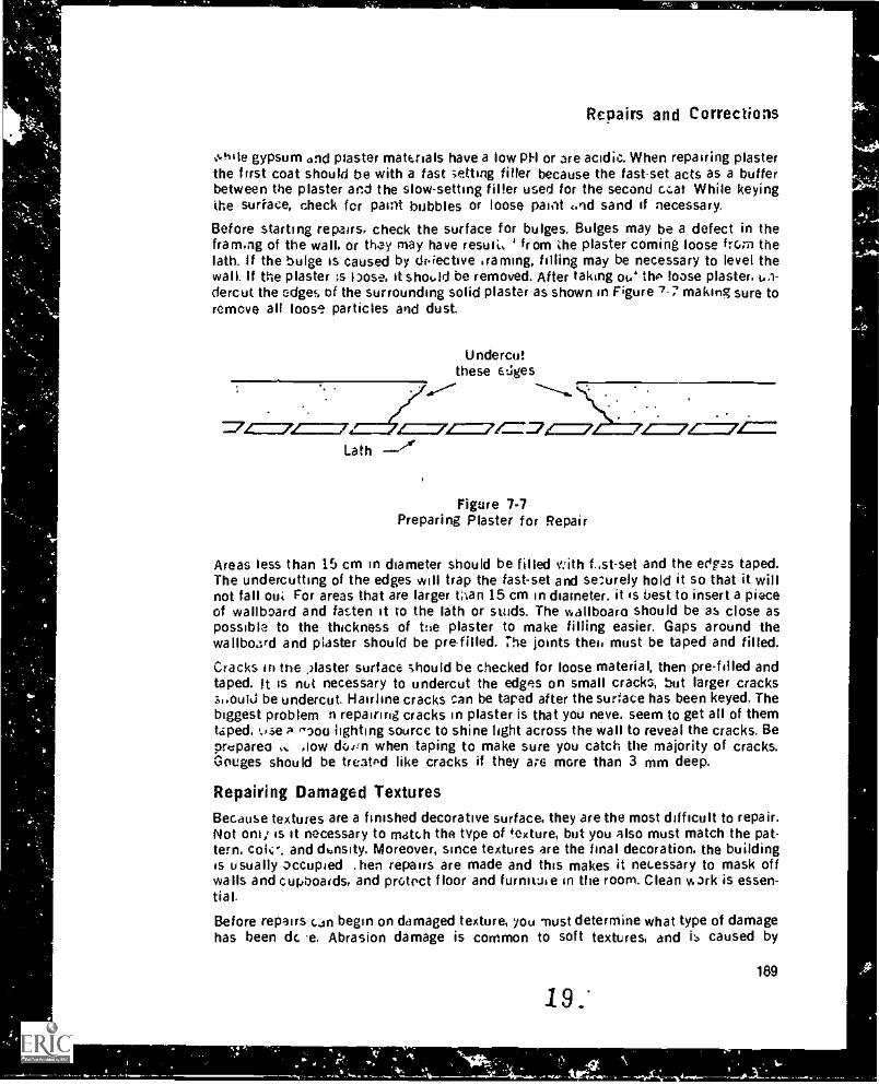
Repairs and Corrections
.0111e gypsum old piaster materials have a tow PH or are acidic. When repairing plasterthe first coat should be with a fast vetting tiller because the fast-set acts as a bufferbetween the plaster and the slow-setting filler used for the second coal While keyingthe surface, check fcr paint bubbles or loose paint :.nd sand if necessary.
Before starting repairs, check the surface for bulges. Bulges may be a defect in thefram.ng of the wall, or they may have result. ' from the plaster coming loose from thelath. If the bulge is caused by dr'iective 'raining, filling may be necessary to level thewall. If the plaster is hose, it shotad be removed. After taking ot.' tho loose plaster, 61-dercut the edges of the surrounding solid plaster as shown in Figure 7-7 making sure toremove all loos' particles and dust.
Undercutthese EL:ges
=7=7 4==7/=4=7/ 4=.Lath
Figure 7-7Preparing Plaster for Repair
Areas less than 15 cm in diameter should be filled '.'ith f..st-set and the Ores taped.The undercutting of the edges will trap the fast-set and securely hold it so that it willnot fall oul For areas that are larger tnan 15 cm in diameter. it is best to insert a pieceof wallboard and fasten it to the lath or studs. The wallboard should be as close asPossible to the thickness of the plaster to make filling easier. Gaps around thewallboard and plaster should be prefilled. The joints the', must be taped and filled.
Cracks in the faster surface should be checked for loose material, then pre-filled andtaped. It is nut necessary to undercut the edges on small cracks, but larger crackssuouiti be undercut. Hairline cracks can be taped after the surface has been keyed. Thebiggest problem n repairing cracks in plaster is that you neve. seem to get all of themtaped. use A r-aod lighting source to shine light across the wall to reveal the cracks. Beprupared doiin when taping to make sure you catch the majority of cracks.Gouges should be treat'd like cracks if they are more than 3 mm deep.
Repairing Damaged TexturesBecause textures are a finished decorative surface, they are the most difficult to repair.Not oni; is it necessary to match the type of texture, but you also must match the pat-tern. and thnsity. Moreover, since textures are the final decoration, the buildingis usually occupied . hen repairs are made and this makes it necessary to mask offwalls and cupoaids, and prutoct floor and furnituie in the room. Clean work is essen-tial.
Before repairs can begin on damaged texture, you must determine what type of damagehas been dc e. Abrasion damage is common to soft textures, and is caused by
19
-`
189
Module 7
umething rubbing against the surface. The aggregate may have fallen off or a tape mayhave lifted In either case the texture should be scraped back as far as necessary to per-mit repairs to the joints. While scraping, bear in mind that textures will not hide ridgesor ;cratches. 1 o prevent the repair job from looking repaired, scrape the texture so thatthe edges are feathered, as shown in Figure 7-8. By feathering the edges you can easilyblend the overspray into the old texture. Large repair jobs on texture are easiest with ahand-held hopper and compressor. Smaller jobs can be repaired with a commercialpatching tool.
Abrupt edges
eb - -,...:25:dtz; ;Ti./5._7/-/-'1,1P '11-g.an--__
Feathered edges
-.I- - - -: : . . ..
Wrong Right
Figure 7-8Feather the Edges Prior to Repairing Texture
Fire damaged texture that is repairable usually has some scorch marks or is darkenedby smoke. Either of these defects require that the surface be sealed and painted beforeit can be re-textured. To get a good seal, the material must dry quickly. Latex paints andoil paints are not satisfactory for sealing because they stay wet long enough for thestain to bleed through. Instead use a polyvinyl alcohol (PVA) sealer. It dries fast, sealsthe surface of the stain, and provides a good base for paint. The paint is necessary be-cause the PVA seals the stain but does not hide it. Note that there are one-coat paintsavailable that will seal the stain and also make it white. The drawback is that thesepaints are very volatile and must be used in well-ventilated areas. Also the applicatormust wear a respirator approved for toxic vapors.
Water stains require a very fast drying material. PVA does not dry fast enough to sealwater stains and they will bleed through. Use lacquer or similar material and have goodventilation. After the seal has dried, apply a coat of paint. It may also be necessary tore-texture.
"Photographing" or "flashing joints" is generally caused by poor sealing of the surfaceof the wallboard before the surface was textured. If joints show through after texturingyou must repaint the ceiling. When repainting soft textures, the paint must be sprayedbecause a roller will remove the aggregate from the ceiling. Hard textures may be donewith a long haired roller.
SUMMARY
Repairs to filling defects should be done while the filler is wet so that shrinkagewill be uniform.When making repairs to filler that is still wet, make sure the blade is wet withfresh filler or water.
190
19&
Repairs and Corrections
Always move the blade parallel to the scratch or ridge that you are trying toremove.
Tape may be used to repair holes up to 8 cm diameter. Glued wallboard patchescan be used for holes up to 15 cm diameter. Holes larger than 15 cm need to havebacking installed and a piece of wallboard screwed to the backing.Recently painted surfaces may be keyed by sanding wr scoring the surface. Olderpainted surfaces or greasy surfaces should be chemically keyed.Cracked tapes should be removed before repair work is started. Cracked beadsmust be securely fastened before refilling.Shrunken filler may be refilled after the surface is keyed. Hollows generally takethree coats to finish.If ridged tape is firm it need only be filled, but if it is loose it should be removedand new tape applied.With nail pops or loose filler around fasteners. either refasten the existingfastener or if that is not adequate apply a new fastener.Water damaged and fire damaged wallboard needs to be replaced.Past-set should be used as the first coat when repairing exposed plaster. Cracks inplaster may be pre-filled and taped. Ridged joints should be cut out. prefilled andreta ped.
Large holes 'n plaster should be patched with wallboard, then taped and filled.Texture used to repair a ceiling must be the same as that originally used. Texturemust Wend smoothly with surrounding texture. Abrasion damage must be re-textured. Stain damage may be sealed and painted if no abrasion exists.
EXERCISE
1. What is the advantage of making repairs while filler is still wet?2. Why is it necessary to use fresh filler when making repairs in wet filler?3 True or False? If you are careful, you can sand out a ridge.4. How would you repair a 5 cm hole? A 12 cm hole? A 20 cm hole?5. Why is keying necessary when making repairs to painted surfaces?6. True or False? All ridged joints can be repaired by refilling.7. What is the procedure for repairing nail pops?8. Why is fast-set used as the first coat when repairing exposed plaster?9. How would you decide to scrape a textured ceiling or to simply repaint it?
10. When scraping damaged texture the edges of the scraped area should be
11. What is supposed to happen when you apply sealer to a stained surface?12. What does a finisher use (1) PVA and (2) lacquer for?13. What defects can a bulging plaster wall indicate?
199 191
Factors AffectingDrywall Finishing
MODULE 8
INTRODUCTION
Even though taping and filling are the vis:ble results of a drywall finisher's work, theyreflect only about one-third of the knowledge the finisher must have. A finisher mustalso know the materials needed for the job, what they are made of, what characteristicsthey possess and what applications they are suitable for. The finisher must be able torecognize when a surface is ready to work on, and be aware of types of decoration thatmay be applied to the finished wall. Equally important, the finisher must have a generalknowledge of the work that is done before and after the taping and filling in order tounderstand and be able to correct problems that arise with drywall.
Finish ScheeulesA finish schedule is a description of what is to be done to a surface. Finishingschedules dre important to drywall finishers because the work that they do on a wall orceiling is dependent on the finish that v 'II eventually go on the surface. The finishschedule accompanies the blueprints and is often divided into sections. It alwaysrefers to the blueprints in terms of the location of the surfaces. Abbreviations are usedto describe finishes and structures.
Although it is impossible to discuss a general finish schedule because architects usemany types, there are, however, certain conventions or basic rules that apply to mostfinish schedules. Finish schedules have four headings. rooms, floors, walls, ceilings.Note that with architectural charts such as finish schedules you should carefully readthe headings and labels, they are there for a good reason and are important in findingthe information you need.
Room identifiersRooms are given by name or number, or, in a project with many rooms of similar sizeand shape. they are given a compass point location in the building. If the rooms arereferred to by compass point you must know how the building sits in rel i on to thecompass points.
The floor plan in Figure 8.1 shows the rooms most commonly found in a house. If therooms were to be identified by compass point, the direction indicator on the right-handside would be used as a reference point. For example, bedroom number 1 would be in-dicated as the northwest bedroom, and bedroom 2 the southwest
193
200
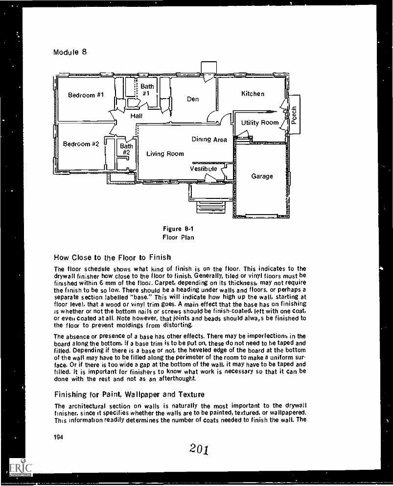
Module 8
Bedroom #1
Bedroom #2
Utility Room
Living Room
Dining Area
VestibuleGarage
Figure 8 -1Floor Plan
How Close to the Floor to FinishThe floor schedule shows what kind of finish is on the floor. This indicates to thedrywall finisher how close to the floor to finish. Generally, tiled or vinyl floors must befinished within 6 mm of the floor. Carpet, depending on its thickness, may not requirethe finish to be so low. There should be a heading under walls and floors, or perhaps aseparate section labelled "base." This will indicate how high up the wall, starting atfloor level, that a wood or vinyl trim goes. A main effect that the base has on finishingis whether or not the bottom nails or screws should be finish-coated, left with one coat,or even coated at all. Note however, that joints and beads should alwa,s be finished tothe floor to prevent moldings from distorting.
The absence or presence of a base has other effects. There may be imperfections in theboard along the bottom, If a base trim is to be put on, these do not need to he taped andfilled. Depending if there is a base or not, the heveled edge of the board at the bottomof the wall may have to be filled along the perimeter of the room to make a uniform sur-face. Or if there is too wide a gap at the bottom of the wall, it may have to be taped andfilled. It is important for finishers to know what work is necessary so that it can bedone with the rest and not as an afterthought.
Finishing for Paint, Wallpaper and TextureThe architectural section on walls is naturally the most important to the drywallfinisher, since at specifies whether the walls are to be painted, textured, or wallpapered.This information readily determines the number of coats needed to finish the wall. The
194
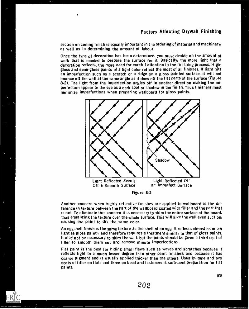
Factors Affecting Drywall Finishing
section on ceiling finish is equally important in the ordering of material and machinery,as well as in determining the amount of labour.
Once the type of decoration has been determined, you must decide on the amount ofwork that is needed to prepare the surface for it. Basically, the more light that adecoration reflects, the more need for careful attention in the finishing process. High-gloss and semi-gloss paints of a light color reflect the most of all finishes. If light hitsan imperfection such as a scratch or a ridge on a gloss painted surface, it will notbounce off the wall at the same angle as it does off the flat parts of the surface (Figure8.2). The light from the imperfection angles off in another direction making the im-perfection appear to the eye as a dark spot or shadow in the finish. Thus finishers mustminimize imperfections when preparing wallboard for gloss paints.
Light Reflected EvenlyOff a Smooth Surface
Light Reflected Offar Imperfect Surface
Figure 8-2
Another concern when highly reflective finishes are applied to wallboard is the dif-ference in texture between the part of the wallboard coated with filler and the part thatis not. To eliminate this concern it is necessary to skim the entire surface of the board,thus equalizing the texture over the whole surface. This will give the wall even suction,causing the paint to dry the same color.
An eggshell finish is the same texture as the shell of an egg. It reflects almost as muchlight as gloss paints, and therefore requires a treatment similar to that of gloss paints.It may not be necessary to skim the wall, but the joints should be given a third coat offiller to smooth them out and remove minute imperfections.
Flat paint is the best for hiding small flaws such as waves and scratches because itreflects light to a much lesser degree than other paint finishes, and because it hascoarse pigment and is usually applied thicker than the others. Usually, tape and twocoats of filler on flats and three on bead and fasteners is sufficient preparation for flatpaints.
195
202
Module 8
The placement of light fixtures can play an important part in exposing defects, regard-less of the reflective quality of the paint. Lights positioned so they shine across a wallor ceiling create shadows similar to those made by a light used to check a finishing jobfor defects. A small bulb can make minor imperfections appear major. In places wherelights shine across a wall or ceiling, the surface must be treated the same as for a highgloss finish. Extreme care must be used when sanding as even fine lines from the sandpaper will appear as deep gouges.
Wall coverings come in many textures and thicknesses. The thicker the paper or vinyland the rnugher the texture, the more it will cover. For example, a heavy vinyl paperwith a weave finish covers most everything ano the surface need only be flat andsmooth with one coat on the flats and two on the beads. On the other hand, foil papershows as many imperfections as a high-gloss paint. The wall should be treated thesame as for the high-gloss paint to eliminate imperfections that will cause ripples orbumps on the surface of the paper.
The rule applying to preparation of wallboard for textures is similar to that applying towallpaper: the rougher the texture the greater the hiding power. Splatter texturesrequire the same finish as flat paints. Rough textures with a loose aggregate willrequire a flat surface with no scratches or ridges. Self-priming textures withpolystyrene aggregate will cover almost all imperfections except for deep gouges orhigh ridges.
Examples of Finishing SchedulesAt the back of this module there are four common examples of finishing schedules.Refer to these schedules as you read the following discussions on them.
Finishing Schedule: Example IThis schedule has five major headings. The information is indicated by the black dotunder the heading. The rooms are given a name and number. "Vest." refers to vestibuleor entrance way. "Rm" is room and "atterici." means attendants. The only nroblem hereis that you will have to search the blueprints to find the rooms marked with the samenumbers as on the finish schedule.
The flooring will be a low-profile type, that is, it will not be raised much above the subfloor level. This c )uld mean that the bottom of the wall will have to be finished. Thewall section is subdivided into three parts. There is to be a base trim; all rooms are tohave a rubber base, which comes in widths of 60 mm and 100 mm. This means that thebottom nails will not need to be done and that any imperfections along the base will becovered. By knowing this and not giving extra attention to the bottoms, you will save alot of time and money for yourself or your employer.
The "dado" is the lower part of a wail defined by a different color or material. The wallsin Example 1 do not have a dado, so it is of no concern. The "field" is the section of thewall that will be decorated. In this case, all but one room will have painted walls.However, this does not help very much because it does not state what type of paint is tobe used. Without knowing the type of paint, you cannot determine the number of coatsof filler required in preparation for the paint. There is a similar problem with theceiling. It is not stated whether the acoustic ceiling is texture spray or tile, and the typeof paint is not given. These factors could have been explained in the "Notes" but forsome reason were omitted. Before you can complete the finish, you must know this in-
196 203
Factors Affecting Drywall Finishing
formation. You can tape and put on the first coat, but you will have to know what thefinish is before putting on the second coat.
Finishing Schedule: Example 2Example 2 is different from Example 1 in that the information is laid out in morespecific areas. The same headings are used but they are major headings which makesthe information easier to find. The rooms are named and numbered but there is nomention of whether the rooms can be found by looking up the numbers on theblueprints. You may have to look for the names, or simply know what area is beingdiscussed.
Again, the information for each room is indicated by black dots in the appropriatesquares. This schedule is easier to understand if it is read room-by-room. The vestibulewill have a quarry-tile base, which should be at least 150 mm high. It will also havevinyl paper up to the 1350 mm mark, although this does not help much because thethickness on the texture of the vinyl is not given. The ceiling is textured, but the type oft sture is not stated. The women's lavatory is tiled up to the 2100 mm mark; thus anywallboard below that mark will be hidden and require less work. Again, the type of paintto be used is left out and, for that matter, whether the walls are to be painted or tex-tured.
Finishing Schedule: Example 3Example 3 is a little trickier because you must first be familiar with the key. The keydefines the abbreviations used under the basic headings. This schedule is more com-plete, providing more of the information required for the drywall finisher to completethe job. The vestibule in this case has a terrazzo floor with a terrazzo base. The basewill extend up the wall for at least 100 mm. It will have a dado of 79 mm of clear vinylplastic, with the rest of the wall being done in gloss paint. This kind of finish means ex-tra work to get the wall smooth and blemish-free. Note that there seems to be someconfusion about the ceiling, as it is unlikely that the acoustic tile will be painted withgloss paint.
These three examples lack information that is vital to the finishing process. In suchcases you must refer to the blueprints or to the written specifications for additional in-formation.
Finishing Schedule: Example 4Example 4 combines written information and abbreviations. The written method poten-tially allows the architect to give more of the details needed by the finisher. Themanager's office, for example, will have carpet on the floor, with a 100 mm vinyl base.Two of the walls will be covered with vinyl, which means that the walls will not have tobe finished to the floor, but the rest of the walls may have to be finished for paint. Theceiling in the office will be acoustic tile, so it is of no concern to the drywall finisherother than its height. It is always safe to assume that the full height of the wall must befinished regardless of the height of the ceiling. This is done for fire protection.
Blueprint Written SpecificationsWith every set of blueprints there will be a set of written specificatinns that tell howthe work must be done and under what conditions. You have !, look through the
204197
,*
Module 8
specifications to find those pertaining to drywall, since usually they are not set apartfrom the others. These requirements must be rigidly adhered to because they state thedesired quality of workmanship. Any aspect of the job that does not meet thespecifications can be rejected. Changes in brand names of material must have the ap-proval of the architect. The architect can be a strong deciding factor in whether youand the company get paid for the job.
Note that it is a good idea to check the written specifications against the national,regional and local building codes, as well as the product manufacturer's specifications.Inquire about any differences before starting the job.
The following specifications relevant to drywall finishers are described in detail in thewritten specifications.
Examination of the framing that receives the wallboard or the wallboard surface that istv be :aped and filled.
By starting a job you indicate that you accept the framing and wallboard surfacesand therefore must assume responsibility for correcting problems resulting fromthem. This is why it is important that you know what good framing and wallboardapplication look like. Similarily, finishers should know what completed electricaland plumbing work look like because these should be installed before thefinishing begins.
Delivery and storage:
Materials should be delivered to the job undamaged, and stored in such a mannerthat they will stay that way.
Protection:The specifications descrbe the materials you must protect from damage whileyour work is progressing For the drywall finisher this usually includes everythingin the building.
Environmental conditions:These are perhaps the most overlooked yet the most important factors influencingthe finished drywall product. This section outlines in detail the minimum dryingtemperatures and times required.
Materials:The specifications give information concerning all the materials from the boardfasteners to tape and filler, including the accepted minimum standards for thematerials. It is here that brand names of materials are found.
Application of wallboard:This should refer to National Building Code minimum standards for applyingwallboard.
Control joints:The specifications describe control joints stating where they should be placed andhow they should be finished.
Trims:The specifications describe where and what types of trims are to be used.
198
205
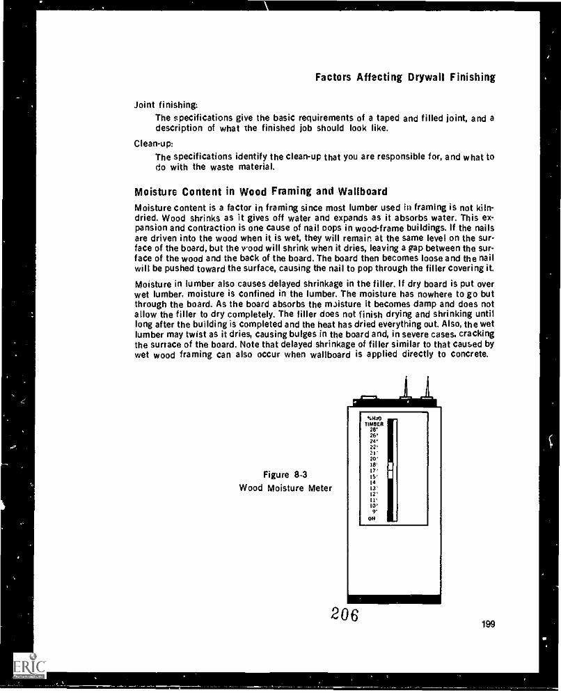
Factors Affecting Drywall Finishing
Joint finishing:The specifications give the basic requirements of a taped and filled joint, and adescription of what the finished job should look like.
Clean-up:
The specifications identify the clean-up that you are responsible for, and what todo with the waste material.
Moisture Content in Wood Framing and WallboardMoisture content is a factor in framing since most lumber used in framing is not kiln-dried. Wood shrinks as it gives off water and expands as it absorbs water. This ex-pansion and contraction is one cause of nail oops in wood-frame buildings. If the nailsare driven into the wood when it is wet, they will remain at the same level on the sur-face of the board, but the wood will shrink when it dries, leaving a gap between the sur-face of the wood and the back of the board. The board then becomes loose and the nailwill be pushed toward the surface, causing the nail to pop through the filler covering it.
Moisture in lumber also causes delayed shrinkage in the filler. If dry board is put overwet lumber, moisture is confined in the lumber. The moisture has nowhere to go butthrough the board. As the board absorbs the mJisture it becomes damp and does notallow the filler to dry completely. The filler does not finish drying and shrinking untillong after the building is completed and the heat has dried everything out. Also, the wetlumber may twist as it dries, causing bulges in the board and, in severe cases, crackingthe surtace of the board. Note that delayed shrinkage of filler similar to that caused bywet wood framing can also occur when wallboard is applied directly to concrete.
Figure 8.3Wood Moisture Meter
206
%MO111411E4
2826*24'22°21'20'18'I?'15'1413'12'11'10'
OH
199

Module 8
When gypsum wallboard is being made, approximately 4 kg of water per square metreis driven off in the drying process. It is possible that the same amount of water can beabsorbed back into the core of the board under very damp conditions. If this should oc-cur, the drying process of filler will be extended considerably.
To measure the moisture content of wood and wallboard, use a wood moisture metre(Figure 8-3). It has two prongs that are pushed into the surface of the wood orwallboard. These prongs should be inserted as far as they can go to ensure that you arenot getting just a surface reading. Readings should be taken at the edges and the mid-dle of the material to get an average of the moisture content. The moisture content ofstuds at boarding time should not be more than 15 %, and the moisture content ofwallboard at taping also not more than 15%. Be careful not to let the prongs contactmetal.
Moisture meters work on the principle that vifoer conducts electricity. A battery sup-plies the power to the prongs. When activated, the current flows from one prongthrough the moisture to complete the circuit to the other prong. The flow of the elec-tricity is then measured by a meter and shown on a scale graduated in percentages. Themore water or moisture present the greater the flow of electricity and the higher thereading on the scale.
If a moisture meter is not available there are several ways of telling if wallboard has ahigh moisture content. Damp board can be felt with your hands. The surface will feelcold, and when your hand is run over the surface you will feel a slight pull orresistance. Also, the paper will have a spongy touch to it. Another indication of dampboard is when you drive a fastener through the board into a framing member it will godeeper than normal, without cutting the paper.
To get an acceptable moisture content in wood studs and wallboard, heat and ven-tilation should be applied to a building at least 72 hours before the wallboard goes up,and not have been turned off more than 24 hours before taping is started.
Proper Drying Conditions For Filler
Temperature and Hull. dityBecause filling compounds must be mixed with water and allowed to dry, two of themost important variables in the finishing process are temperature anG humidity. Tem-perature refers to the presence or the lack of heat. Humidity is expressed in terms ofrelative humidity, that is, the amount of water vapor present in the air compared withthe greatest amount possible at the same temperature. Relative humidity (RH) is alwaysexpressed in percentages. It is measured with a sling psychrometer.
It is important to note that temperature and humidity cause the majority of allwallboard problems. This fact is slowly being recognized by the industry largely be-cause of expensive callbacks to correct temperature and humidity-related wallboardproblems.
Relative humidity is directly related to heat. Since warm air can hold more moisturethan cold air, the higher the temperature the greater the amount of moisture that isabsorbed (Figure 8-4). For example on a very foggy day on the coast, the humidity maybe as high as 98 per cent. As the temperature rises the fog disappears because the airabsorbs the water droplets suspended in the air. The same process occurs when you
200
201
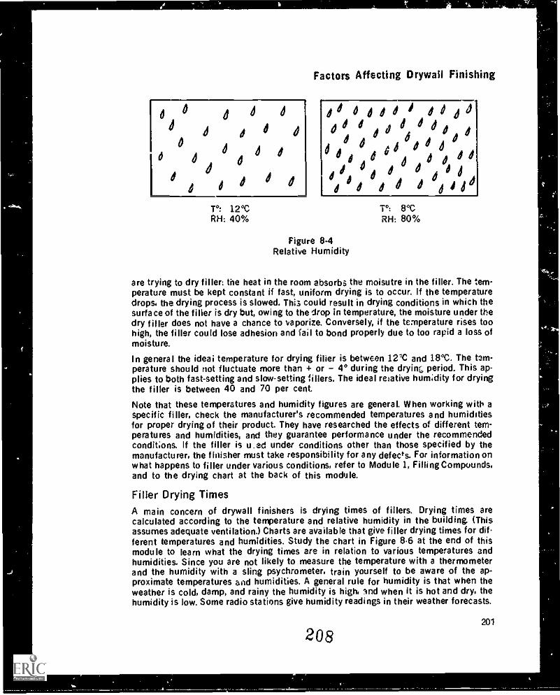
°
0
1 d
1
e
1
d d
d
T°: 12°CRH: 40%
Factors Affecting Drywall Finishing
di 0410
d 010 dd
dedjd6
Figure 8-4Relative Humidity
T°: 8°CRH: 80%
are trying to dry filler: the heat in the room absorbs the moisutre in the filler. The tem-perature must be kept constant if fast, uniform drying is to occur. If the temperaturedrops, the drying process is slowed. Thi3 could result in drying conditions in which thesurface of the filler is dry but, owing to the drop in temperature, the moisture under thedry filler does not have a chance to vaporize. Conversely, if the temperature rises toohigh, the filler could lose adhesion and fail to bond properly due to too rapid a loss ofmoisture.
In general the ideai temperature for drying filler is between 12'C and 18°C. The tem-perature should riot fluctuate more than + or 4° during the dryinc, period. This ap-plies to both fast-setting and slow-setting fillers. The ideal relative humidity for dryingthe filler is between 40 and 70 per cent.
Note that these temperatures and humidity figures are general. When working with aspecific filler, check the manufacturer's recommended temperatures and humiditiesfor proper drying of their product. They have researched the effects of different tem-peratures and humidities, and they guarantee performance under the recommendedconditions. If the filler is u.ed under conditions other than those specified by themanufacturer, the finisher must take responsibility for any defects. For information onwhat happens to filler under various conditions, refer to Module 1, Filling Compounds.and to the drying chart at the back of this module.
Filler Drying TimesA main concern of drywall finishers is drying times of fillers. Drying times arecalculated according to the temperature and relative humidity in the building. (Thisassumes adequate ventilation.) Charts are available that give filler drying times for different temperatures and humidities. Study the chart in Figure 8.6 at the end of thismodule to learn what the drying times are in relation to various temperatures andhumidities. Since you are not likely to measure the temperature with a thermometerand the humidity with a sling psychrometer, train yourself to be aware of the ap-proximate temperatures and humidities. A general rule for humidity is that when theweather is cold, damp, and rainy the humidity is high, lnd when it is hot and dry, thehumidity is low. Some radio stations give humidity readings in their weather forecasts.
208201
_
-
ti
Module 8
Note that in woodframe houses with basements, two relative humdity conditions willbe found. The upper wood-framed part of the house will have a low relative humiditybecause the heat is directed to the top of the house and the moisture in the framingmembers is readily evaporated. The basement, on the other hand, is constructed of con-crete that will retain water, thus raising the relative humidity. Moreover, heat will notbe directed into the basement, which means that the temperature will be low, furtherincreasing the relative humdity.
VentilationThere is a common misconception that heat is all ihat is necessary for proper drying.Equally important to heat in drying is ventilation.
Witnout ventilation, heat is of limited value because water will evaporate until the airbecomes saturated, then the drying process will stop. if air is to move through abuilding there must be two openings one for the air to enter, the other for the air toescape. The general rule is the larger the area to be ventilated, the larger the openings.On most jobs ventilation can be accomplished by having a combination of doors andwindows open at least 5 cm. If it is a dry, warm day the ve,:tilation should be increasedto provide better drying conditions.
Most general contractors like to have their buildings secured, which means having anypossible access to the building locked tight. Groundfloor windows can be locked in anopen position with pieces of wood or metal preventing them from being opened furtherfrom the outside. Buildings not having windows that open must have circulating fans tomove air around. In such a building, especially large ones, circulation of the air plussome form of temporary heat wall be required for drying.
Checking For Inspection SlipUpsEvery building must undergo some inspections, whether it is residential or commercial,single dwelling or highrise. The forms of inspection will vary from district to district, soyou must make yourself aware of local inspection procedures. The most common in-spections relate to clectricai, plumbing, framing, and insulation work. The basis ofmost inspections will be the National Building Code, but local regulations will oftensupersede these regulations, so make yourself aware of them as well. Your primary co Pcern is whether the basic inspections have been completed, and if so whether the wrrkhas passed inspection. Inspectors check only for the quality of the work to ensure thatit meets the regulations. A basic inspection card states the name of the district and thepermit number of the job, It also states what has been inspected and has a section forremarks, acceptance or rejection, and the inspector's signature.
While most inspections should be completed satisfactorily, it is not uncommon forsome things to be missed. The information here is not intended to make you aprofessional inspector, but rather to make you aware of all the things that if notchecked beforehand can cause expensive problems later on.
Electrical WorkAll electrical outlets should be in place by the time you start your prejob inspection.Because they are put in place before the wiring is installed, it is wise to check that alloutlets have wires running to them. Not all the boxes will be electrical, since telephoneand cable-television companies install their own outlets. These outlets do not have a
202
209
Factors Affecting Drywall Finishing
back on the box since they provide support only for the finishing cover. Switches aregenerally located beside a door inside a room. They are usually 150 mm from the floor.Every room should have a light receptacle and a switch, except for living rooms andbedrooms, which can have switch-controlled outlets. Switches and outlets in kitchensshould be 20 cm to 30 cm from the top of the counter. Wall receptacles are usuallyplaced 20 cm from the floor. Electrical conduit is the only method of installing wiresoutside the walls. Make sure that all electrical conduit feeds into a box and that nolocse wires are exposed.
Except in kitchens, bathrooms, laundry rooms, water-closet rooms, utility rooms andhallways, wall outlets should be installed in every finished room or area in a dwellingso that no point along the floor line of any useable wall space is more than 1.8 m froman outlet in the same roam. The rooms excepted from this code should have as manyoutlets as needed with at least two in the kitchen. Generally speaking, bathrooms havea light switch and receptacle, an electric shear outlet, and an outlet which is connect-ed to a no-fault breaker switch.
Wires for thermostats are usually located centrally in the hallway where the averagetemperature of the area can be monitored. They are usually 150 cm from the floor. Thewires are different colors and are not attached to one another. Doorbell wires aresimilar and are usually placed in the same area but higher on the wall. Electric and hotwater heat may have thermostats in every room.
If you find that wires are missing or that common electrical installations are notpresent, check with the person in charge of the site.
Plumbing
Plumbing may be found inside the walls in bathrooms and kitchens. Hot and cold waterpipes and a drain are necessary for hooking up a sink or bathtub. If the pipes are in thewall, make sure that the fixture connections stick out beyond the surface of thewallboard so that they will not be accidentally covered. The bathtub must be in placeb3fore the board is put on the wall. Plumbing pipes that concern the drywaller are: hotad cold water supply pipes, the drain pipes for plumbing ,fixtures and the location ofthe shower arm. It is a good idea to have a short piece of pipe screwed in the showerarm connection extending beyond the wallboard to show the exact location of the arm.Another concern about the plumbing is to make sure that no pipes touch the back ofthe wallboard. If they do, the wallboard may bulge so have the plumber correct thisproblem.
Framing
Drywall is applied to twu basic types of framing: wood construction and steel con-struction. Problems can arise with both types of framing. Without going into details ofthe actual framing, it is possible to recognize the problems and how they can be correc-ted. Drywall finishers will not often get the apportunity to examine framing, but theyshould be aware how framing can affect their work.
Once boarding begins, it means that the framing is accepted as satisfactory. The personboarding then becomes responsible for any defects ir: the framing that affect the finishof the board. This practice is common to all the trades involved in construction. Bydoing a thorough job of inspecting the framing, in addition to the work of other trades,liability in producing an acceptable finished surface is reduced.
203
210
Module 8
The first step is to check the blueprints and make sure that all the walls shown havebeen put into the building. Check the measurements of stub walls, openings, doors,archways, etc., .he locations of stairs and the design and dimensions of unusuallyshaped drops. When certain that al' measurements are correct, check the walls with astraightedge. The longer the straightedge the better because it will make in-consistencies more obvious. Studs that do not conform to the rest of the wall should bemarked, and a carpenter should be called back to either replace or straighten them.Also, the fastening surface of the framing member should be in line with the bottomand top plate. Twisted studs should be replaced since they do not allow the fastenerssufficient depth to grip securely.
The plumb of the wall refers to the vertical angle of the wall to the ceiling and floor.The quickest way to tell if a wall is plumb is to put a level on it. A wall that is out ofplumb will be most noticeable where the entire length of the wall can be seen from oneend. When walls are out of plumb, notify the superintendent of the job that you will notbe held responsible for the appearance of the wall after the wallboard is on. Get this inwriting because verbal agreements are not always remembered.
Although wallboard is a fairly rigid material, it is susceptible to warping. For thisreason the maximum distance between the centers of wall studs should be 400 mm for9.5 mm board, and 500 mm for 12.7 mm and 15.9 mm board. Ceiling framing should be400 mm centers for 12.7 mm board and 600 mm for 15.9 mm board. If ceilings are tobe textured. 15.9 mm board is strongly recommended to prevent sagging.
All framing members to which the board will be attached must be a minimum of 38 mmwide. This ensures that proper support will be given to the board b', providing anadequate surface area of contact between it and the framing member. All joints in theboard except flat joints should have backing material to nail to. This ensures that theboard will not move and cause the joint to crack. When checking backing. look at thecorners and angles to make sure the board can be fastened on either wall. If properbacking is not present make sure it is put in before boarding starts. External cornersaround archways, drops. and valances must be framed to meet requirements and berigid enough to accept the fasteners that will be used in applying the board.
If wood trim is to be used around windows, check to be sure that the door and windowframes have been lest so that the surface of the board will be flush with the edge of theframe. If L-bead is to be used around windows in conjunction with a wood liner, be surethat the board will lie on top of the liner.
Wood StudsWhen inspecting wood studs. chec; the soundness of the wood. If the wood is too soft,have the stud replaced because the fasteners will not hold the wallboard securely to it.All studs must be firm. In interior angles, wood studs should be placed to form and L-shape so that there is enough bracing to fasten the ends of the board to each side. Ex-ternal corners must be framed with three studs to provide proper backing for bothsides of the wall. All openings should be framed with double studs and headers.
One of the main lroblems in wood framing is that the structure of drops, valances, andother enclosures are often not sturdy enough. The minimum size required for framingin such areas is 38 mm r 38 mm. This supplies the necessary rigidity as well asmaking the structure less susceptible to movement and cracks in the finish. If plywoodis used for backing it should be a minimum thickness of 12.7 mm so that it is thick
204
211
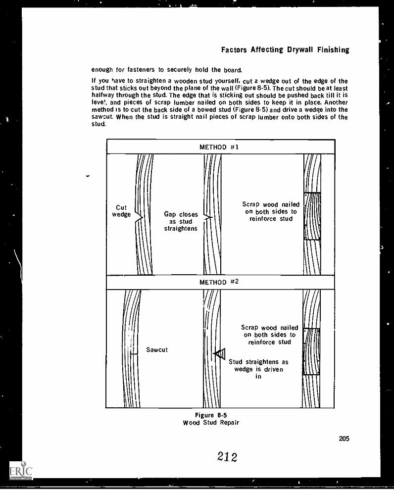
Factors Affecting Drywall Finishing
enough for fasteners to securely hold the board.
If you have to straighten a wooden stud yourself, cut a wedge out of the edge of thestud that sticks out beyond the plane of the wall (Figure 8-5). The cut should be at leasthalfway through the stud. The edge that is sticking out should be pushed back till it islevel, and pieces of scrap lumber nailed on both sides to keep it in place. Anothermethod is to cut the back side of a bowed stud (Figure 8-5) and drive a wedge into thesawcut. When the stud is straight nail pieces of scrap lumber onto both sides of thestud.
METHOD #1
Cutwedge Gap closes
as studstraightens
Pi
Scrap wood nailedon both sides to
reinforce studI
METHOD #2
(I
Sawcut
1
V/11
"401
\
Scrap wood nailed
orreinforcehidssetsostud
Stud straightens aswedge is driven
in
IT
Figure 8-5Wood Stud Repair
205
212
c".
Module 8
Steel StudsThe steel studs discussed here are those 6n non-load bearing walls. When checking thistype of framing, you must make certain that the walls are not attact 4 to load-bearingstructures The wall must consist of a steel track attached to the floor and another oneattached to the ceiling. Steel studs should be screwed or clinched into position ateither end of the stud so they will not move. The door openings must be framed so thatthe metal door channel easily slides into place. The frame must be able to be fastenedat any point along its length. Check for the size of the doors to be used. if the doors areto have wood frames, pieces of 2.5 cm K 10 cm wood must be attached to the inside ofthe framed door area. Allowances must be made in the framing to allow for inclusion ofthe wood.
A steel stud seldom will be out of place, but when it is, the cause is either that thechannel was not laid down properly or that someone kicked a stud out of place. Torepair a track that is out of place is a major operation. A stud that is bent or loose mustbe replaced or screwed back into position. Both these repair jobs require special toolsthat the drywall finisher does not usually carry. The need for repairs should be broughtto the attention of the steel-stud installer so that they will be done properly.
Steel studs have knock-outs that allow wiring and other services to pass through themwithout affecting the strength of the stud. These must be aligned so that the servicescan pass through easily and continuously.
Wallboard
Wallboard may be applied either horizontally or vertically. Horizontal application kspreferred for the following reasons:1. It is more economical as longer sheets can be used.2. It reduces lineal footage of joint treatment by 2S per cent, thus cutting labor and
material costs.3. More framing members can be tied together per panel.4. It gives greater coverage of irregularities in framing.5. Joints on walls are at a convenient height for finishing.6. The board is easier to handle
Vertical application is preferred where the ceiling is higher than the standard 2 400mm or where the wall is narrower than 1 200 mm.
Butt joints should be staggered and placed as far as possible from the centre of a wallor ceiling. The greatest amount of movement will occur in the centre of a room. and abutt joint will not accept much movement without cracking or buckling. Butt joints inthe middle of a room are also more noticeable if filled incorrectly since they are thecenter of the field of vision when entering a room. Butt joints should always befastened at a framing member and run parallel to the framing. There should be nofloating joints except flats between the studs.
Fasteners should be driven in so that they hold the board securely in place, and thepaper surrounding the fastener should not be broken. Fasteners should be no closerthan. 5 mm to an edge of the board. Nails must be spaced every 18 cm on ceilings andevery 20 cm along vertical wall supports. Double nails may be spaced 5 cm apart every30 cm. If screws are being used they must be placed every 30 cm on vertical supports
206
213
I
i
i
Factors Affecting Drywall Finishing
or ceilings. The nails must be long enough to penetrate the wood 3.5 cm whereas thescrews must be long enough to penetrate the support at least 3 cm.
Lamination of two layers of board provides a stronger wall, better sound-proofing, andgreater fire protection; it also means that there are fewer fasteners to fill. The firstlayer is nailed or screwed on in the normal way and the second layer is fastened inplace with an adhesive, with the Joints running opposite to those in the first layer.Double-headed nails are normally used to hold the board in place until the adhesivedries or sets, and are then removed.
Beads and moldings should be on tight. There should be no ripples in the flange of thebead and no kinks in the finishing edge of the bead. Ripples can be re-fastened but anybead with kinks must /3e removed sa that the finish of the bead will not be affected.Bead that has been removed should not be used again because the metal will stretchand it is impossible to put it back on straight. Joints in bead should be tight and level.if they are not tight and level they should be taken off and replaced. Paper bead shouldhave no bubbles.
Some of the problems finishers can find with the boarding are: spaces between joints,rippled beads, fastener heads above the surface of the board, uneven joints, brokencore, loose face paper, improper joints (i.e., floating butt joints), cracked face paper,gouges, oversized holes for outlets and pipes.
Method of Taping and FiningThe method of taping must be decided prior to starting the job. The size of the job willdictate the methods of taping and filling. is the job small enough for one person to doin one day by drytaping? Will it need two workers to use the hopper method to tape andload in one day? Or will three workers and a taping machine be needed? Essentially,you need enough work at a job-site to be able to complete a coat in one day. One personshould be able to drytape 350 to 450 m2 of board per day. Two should be able to tape2240 m2 per day with a hopper, while three could tape 3150 m2 with a taping machine.Machine taping may be faster than the hopper method but cleanup is longer. Machine-filling is faster than hand-filling, but again the cleanup is longer. Renting or buyingmachines is costly, so you must determine whether the size of the job warrants the ex-pense.
Whatever method is to be used, it is essential that the necessary tools be on the job-site. They should be clean and in good working condition so that no time is lost makingrepairs or adjustments.
Stilts enable the average-sized person to easily reach a height of 2.4 m. But they shouldnot be used when the height of your feet will be more than 60 cm from the ground. Forroom heights greater than 2.4 m, the use of ladders or scaffolds should be considered.Although ladders are easily moved, they permit only small areas to be covered betweenmoves. A small rolling scaffold is good for manoeuvrability where the floor is level andclean to permit its free movement. But it is not practical for areas where your feet willbe higher than 1.5 m from the ground as it becomes very unstable above that height.Where the floor of the working area must be higher than 1.5 m, a widerbased scaf-folding should be used. Check Workers' Compensation Board regulations for propererection and safety aspects of scaffolds.
Wherever scaffolds are used, make sure there are a least two persons present for theduration of the work. This is important to safety as well as to efficiency because the
214
207
Module 8
material can be passed to the higher level without excessive travelling. The person atthe lower level can also help in moving the scaffolds. It is important that all necessarymaterial be present to build the scaffold, and that the scaffold be ready for the workerswhen they arrive on the job.
Handling and Storage of MaterialsStorage of material is another factor that can make a difference not Only in the qualityof the finished product, but also in the amount of work needed to finish the job.
Wallboard is a finished product and should be treated with the same care given tomillwork or pre-finished wood panelling. The better the condition of the board before itis put on the wall the better the finish that can be achieved. The gypsum core of theboard is brittle and breaks if handled roughly. Broken board is useless for a finishingpanel as the internal strength of the board affects the adhesion of the paper on the sur-face. It is essential that the bond between the core and the paper be maintained.
Wallboard should always be carried on its edge. Carrying it flat causes bending, whichreduces the strength of the core, especially !f the surface paper is cracked. Two per-sons should carry a sheet of gypsum board to reduce the risk of banging the edges andcorners, and to save strain on one person moving 1. The board should be held so thatboth handlers are on the same side, with the board resting against the shoulder of thearm carrying the weight. It must be set down in such a way that neither the edge or cor-ners will not be crushed. Although the board will withstand a drop of a few centimetreson a long edge without damage, it should not be dropped on a corner or the core willshatter. Once the edge has been set down, the board can be gently laid flat with theface side up. To prevent nails and small rocks from marring the surface, the last sheetto go on the pile should be face down. Board should be stored flat in a dry place. and inan area of the building where it will not have to be moved except to be put on the wall.It should be away from major traffic areas so that it is not walked on. Make sure theedges of the board don't overhang to avoid breakage should they be stepped on.
Wallboard is highly susceptible to moisture. High-humidity areas must be avoided toensure that the board will remain dry. It should not be laid on a bare concrete floor butrather on a vapor barrier, such as a polyethylene sheet. s:.) that the moisture in the con-crete will not be absorbed by the board. An alternative method is to place pieces ofmaterial called dunnage to form a platform. The dunnage should be at least 10 cmwide, be no more than 40 cm apart and should not be more than 7 cm shorter than thewidth of the board. This method is also recommended for storing board on uneven sur-faces. Board should not be stacked more than 1 m high to avoid warping. ft may beplaced temporarily on edge by leaning it against a wall, but prolonged storage this waywill also cause it to warp. If board must be leaned against a wall make sure the wallrequires no other work to be done on it, because the more the board is moved the morelikely it will be damaged. The temperature in the building at the time of loading shouldnot be lower than the temperature of normal working conditions, 12°C.
Powdered filler is another material that is highly susceptible to moisture. If it becomesdamp it will form lumps in the bag and become impossible to mix. Like the board, fillershould be stored in a warm, dry place, and raised off concrete flooring. Premix fillercan withstand one freeze-thaw cycle, although it is not a good idea.
Although metal bead is not greatly affected by temperature, it should not be left in amoist place ery long. Even though the metal has been galvanized it may rust under ex-
208
215of
Factors Affecting Drywall Finishing
treme moisture conditions. Metal bead should be stored where it will not come in contact with oil or grease, and where it will not be waked on or bent. It should be storedflat, since propping it against the wall could cause it to warp. Remember, once cornerbead is bent the metal stretches and it becomes impossible to put it on straight.
To limit damage to any material, it should not be delivered too far in advance of its useand should be left in the original protective wrapping until it is needed. This ensuresthat it will remain clean and in good condition.
Stains on wallboard are a problem. Virtually any material that is a different color thanthe surface of the wallboard and that is soft or water-solvent will cause a problem inthe finishing of drywall. Some- of the more common staining materials are coffee,blood, rust, ink, and chalk-line marks. These stains will be dissolved by the water in thefillers and textures and will blead through the surface of the covering unless they arefirst treated properly. Oil and latex paints are not suitable treatment because they takeso long to dry and allow the stain to soak. Lacquer or one of the spray-bomb varathaneplastics are best as coatings for stains because of their fast drying qualities.
Protecting Nearby SurfacesThe adage "an ounce of prevention is worth a pound of cure" applies to the protectionof surfaces adjacent to wallboard. At the stage when drywall finishing is done, most ofthe materials surrounding the drywall are finishing materials and must be protectedfrom wet filler, texture, and dust. Wet filler is much easier tl clean than dry filler. Fillerwill always leave a white film on porous substances such as brick and concrete blocks.Filler on unfinished wood will leave a dark area when the wood is stained as the fillerabsorbs more stain than does the surrounding wood. Some textures contain a latex-base paint to whiten them and provide better coverage. When this paint dries on a sur-face, it is impossible to remove without some damage. Some textures contain sand orperlite and when wiped off a surface, even when wet, they may scratch it. Becausethese damages are the fault of the drywall finisher, liability for damage or thereplacement of the damaged material falls on the drywall finisher.
There are many ways to cover areas that require protection. Small areas such as doorjams, window frames, and brick can be protected with masking tape. The tape must beas tight ;0 the gyproc as possible to prevent the filler from leaking under the tape andonto the protected surface. Before removing the tape, run a knife along the edge of thetape to separate the filler on the tape from the filler on the board. If this isn't done thetape will pull off chips of filler from the wallboard.
Masking tape sticks only to clean, dry surfaces. It is useless to try to stick masking tapeto mortar or to a dusty surface. Although the tape will adhere to the particles of sand ordust, the particles will not be secured to the rest of the surface and the tape will beineffective protection. It may help to wipe the area with a dry, clean cloth to improvethe bond. Note also that masking tape will not stick to wet filler.
Do not leave masking tape on the protected surface any longer than is necessary be-cause it can damage the surface by removing part of the finish. On pre-finished heatregisters the paint may peel off with the tape if it is left on too long. Generally speakingthe wider the masking tape the greater your concern should be for the finish of the sur-face It is protecting. Note that if tape dries out it must be removed with a cleaningsolvent thus creating more problems, Avoid putting tape at all on photo-finish panellingand on the paper face of wallboard, since it will damage both of these surfaces.
216
209
t
Module 8
When an area larger than the width of the masking tape needs to be protected, amasking machine may be used in conjunction with a paper apron. When areas such asdoors, windows, or brick work are to be protected, a polyethylene sheet may be more ef-ficient.
Poly is excellent for covering floors or furniture when ceilings are being textured, butonly if it will be walked on for a short time. A tarpaulin is the best protection or a maintraffic area. A tarp is expensive, but it can be used many times and won't slide on thefloor and cause possible injury from falls. Although it is almost impossible to fullyprotect areas from dust caused by sanding filler because it is so fine, poly is probablythe best material to use as it is a non-porous substance and dust cannot pass throughit. Use masking tape to seal the edges.
To prevent dust from entering the duct work of the building, cover the heating outletsand intakes. If possible shut off the circulating devices. Before doing either of these,however, first check with the superintendent to see that damage cannot be done to thesystem. Open the windows for ventilation. Dust control is important because dust, onceit gets into the duct work, circulates throughout the building for a considerable time af-ter the job is finished.
SUMMARY
Job Inspection Check,' itGeneral
1. Has the prev.ous trade work been inspected and did it pass local inspectionrequirements?
2. Did previous trades make a proper clean-up after completing their work?3. Is there anything in the blueprints, the architect's specifications, or the finish
schedule pertaining to the finishing of walls and ceilings?4. Do all electrical outlets have wires running to them and are there wires in all the
electrical conduits?5. Are there any wires for thermostats and door bells?6. Has the necessary plumbing been completed?7. Have the necessary materials been delivered, and if so do they meet
specifications?
Framing8. Are the walls straight and plumb?9. Are there any obstructions sticking out beyond the plane of the nailing surface?
10. Has all the necessary framing around duct work and pipes been done?11. Are studs a maximum of 400 mm centres for 9.5 mm board and 600 mm centres
for 12.7 mm and 16.9 mm board?12. Are all framing members straight with a level fastening surface?13. Are all framing members a minimum of 38 mm wide?14. Have all door and window frames allowed for the wallboard to be applied?
210
217
Factors Affecting Drywall Finishing
Wood Studs15. Are there three studs at all vertical corners?16. Is there backing on both sides of interior angles?17. Are all openings in walls framed with double studs and headers?18. Are any wood studs too soft to securely hold nails or screws and keep the
wallboard tight?19. Is the structure rigid enough for nails?
Steel Studs20. Are all steel studs securely fastened to the track, and is the track securely
fastened to the floor and ceiling?21. Are all steel stud walls free from any load?22. Are door locations framed so that the doors will fit easily and properly?23. Are the holes in the steel studs aligned so that electrical wires and plumbing can
pass through easily and continuously?24. If wooden door frames are to be used, has wood been applied to the steel studs so
that the frames may be nailed in?
Masking Areas to be Protected25. Are there any areas that have to be protected from wet filler or sanding dust?26. Will masking tape, paper apron, polyethylene, or some other means be required
for protection?
Temperature and Humidity27. Was heat maintained at a minimum of 12°C for at least 72 hours before the board
was applied?28. Is the moisture content of the wood studs at or below the maximum of 15 per
cent?
29. During application can the temperature be maintained between 12°C and 18°Cwith a maximum variation of + or 4°C?
30. Can the temperature remain constant for at least 72 hours after the drywall isfilled and finished?
31. Is there proper ventilation so that moisture can escape?32. Is it understood that if temporary heat is supplied that it not be the type that uses
kerosene or stove oil, and that the heater have a thermostat or other control withwhich to regulate the temperature?
Loading and Storing Material33. Will any special equipment be required to load material into the building?34. Is there a dry, level place raised `rom any concrete surface that the material can
be stored upon?35. Will the material be out of the way of heavy traffic areas and be protected from
moisture and damage?36. Will materials be delivered as dose as possible to the time that they will be used?
218
211
Module 8
Finishing Method37. What method of taping will be used for the most efficient application?38. What type of filler will be used to give the best results under the prevailing con.
ditions?39. What type of finish is required on the .:eilings?
Boarding Application40. Does the board meet the architect's specifications?41. Will the board be attached vertically or horizontally?42. Will the board be laminated?43. Have the minimum number of joints been used?44. Are all butt joints staggered and away from the centre of the wall?45. Are joints around openings at least 30 cm from the corners?46. What type of fastener will be used?47. Are all the fasteners set slightly below the surface of the board, and do they hold
the board tight to the framing structure?48. Has the requirement for distance betw fasteners been met?49. A,e all joints tight with no foreign materiai protruding?50. Are all joints fastened to a framing member?51. Are all surfaces flush with no butt edges against a tapered edge?52. Have the cold air returns for the furnace been cut out?53. Are thermostat wires showing at the 150 cm mark?54. Are there any doorbell wires? If so, are they showing at approximately the 210 cm
level?
Beading
55. Are all the beads on tight and straight?56. Check all joints and corners formed by the bead. Are they flush?57. Have a:I electrical outlets and pipes been checked to make sure that there will be
no holes surrounding them when they are finished? Does the finish scheduleprovide for plates?
58. Have all short tapes been applied?59. Have all joints and beads been treated with the required number of coats to sup-
port the final decoration?60. Have you properly cleaned up and removed excess material from the site?
212 219
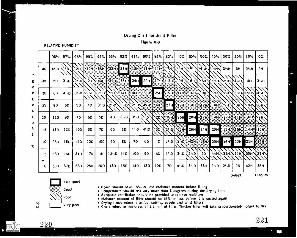
Drying Chart for Joint Filler
Figure 8.6
98% 97% 96% 95% 94% 93% 92% 91% 90% 85%r
80c.* :'0% 60% 50% 40% 30% 20% 10% 0%
40 4'2D `3D 2D MEM 23H,:::::::?.N:::1811::".4:-:-:.:-:.
If! IfTi ..-..F....:.*:-:...........::::1.411::!::1.11f::,_.:".:-:-:-:-:: ::-....::-:::;:'
7Nt
%
`7.-k,
4*/ H \ 3v2H 3H 2' H 2H
35 5D 3'2D 2'2D 2D 1MM 24H 22H. ...7'4:
'.""%v.: 1314::% -:i:::::-:-Ik
\9H k. !n, )\44' H 4H 3t4 H
30 6:1 414D 314D 2'4D 2' D 20-:-...-:..:-::
:4611: 25H:;:;:i:::;:;:::
1011:kIS 1 '1
4', H
25 9D 6D 5D 4D 3'4D 2'4D 2' 6,
2.4D
.
14;0 El ME iiii.Will iii..:Ol.1::.::\N\
20 120 9D 7D 6D 5D 4D 3'2D 3,41) 3D 2D 25H 20H iil2R3:::::::::.::::::.:::::s::::.::
: ;1.1K ::1011"
15 18D 12D 10D 8D 7D 6D 5D 4'4D 4'4D 3D 244D ;:;3£tif: 29H 24H 20H :1411::'- ...
0::+::-::.M
10 26D 18D 14D 12D IOD 9D 8D 7D 6D 4D 3'4D 2'.D::::. ..:-:-
::a1:1: 29H
IISMNIIIMIMIIWN\
26H 23H
30H
::)9H:::.
ft1.Ittle
38D 26D 21D 17D 14D 12'2D 11 D IOD 9D 6D 43 D 312D 2'2D 2D
53D 37D 28D 25D 20D 18D 15D 14D 130 10D 7D 4I2D 3'2D 33D 2'41) 2,'41.1 20 42H 38H
5
0
Board should have 15% or less moisture content before fillingTemperature should not vary more than 8 degrees during the drying timeAdequate ventilation should be provided to remove moistureMoisture content of filler should be 15% or less before it is coated againDrying times relevant to fast setting. casein and vinyl fillersChart refers to thickness of 2-3 mm of filler. Thicker filler will take proportionately longer to dry
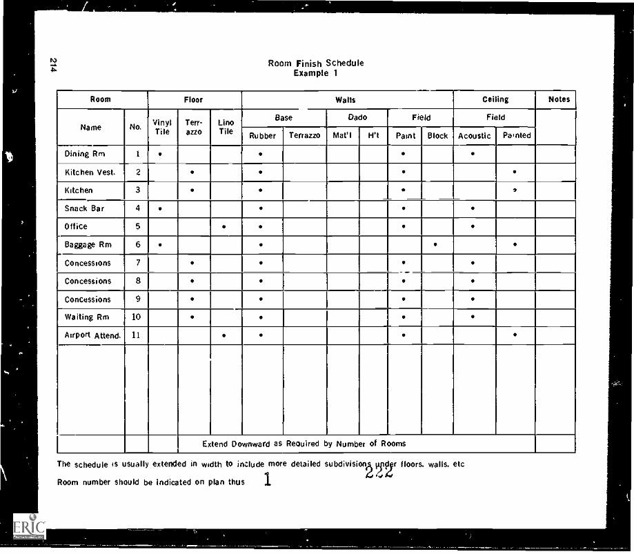
).1
it
...
N.b.
Room Finish ScheduleExample 1
Room Floor Walls Ceiling Notes
Name No. VinylTile
Terr-azzo
LinoTile
Base //ado Field Field
Rubber Terrazzo Mat'l 1 Ift Paint iBlock Acoustic 1 Painted
Dining Rm 1
Kitchen Vest. 2
Kitchen 3
Snack Bar 4
Office 5
Baggage Rm 6
Concessions 7
Concessions 8
Concessions 9 I
Waiting Rm 10
Airport Attend. 11
Extend Downward as Reouired by Number of Rooms
The schedule is usually extended in width to include more detailed subdivisionA Tisr floors. walls. etc.04,1
Room number should be indicated on plan thus 1
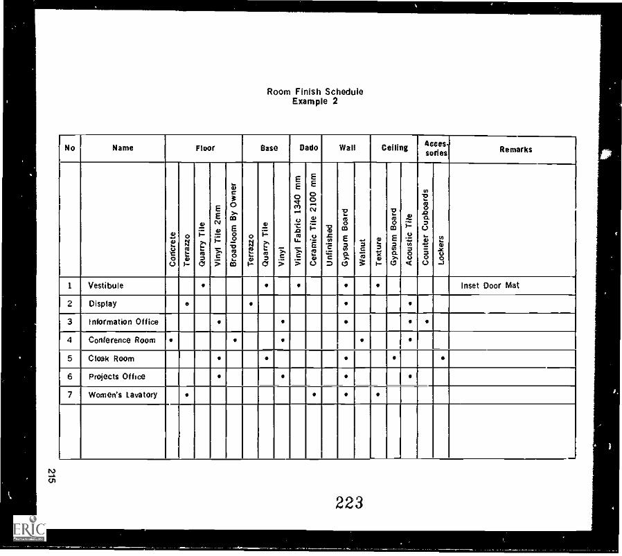
ns
f.T
Room Finish ScheduleExample 2
No Name Floor Base Dade Wall Ceiling Uses-series Remarks
2E
C1-$
0
04mg1
0i:t.'-ga
E
cv
2i.=
S.c5
4)C30al
$zco
cCO
04E4-,1
0
.8.:
>.
'a3.c5
EE
sa0Cr1....
Q7..
1)
T..c5
EE8c7,1
.3.'.-o-.c=E4e
tg-,
C.)
'z152.E-aD
1'aCI3
E30)V4ca
....3763
at*-Zr,1--
-a
galE3in5'4(.1
ai"2ti=4)
nz
in-0
g
10"2=8
c.)
0t=81
1 Vestibule Inset Door Mat
2 Display
3 Information Office,
4 Conference Roomi
5 Cloak Room
6 Projects Office1 I I I 1 1 1 1 I V
7 Women's Lavatory
223
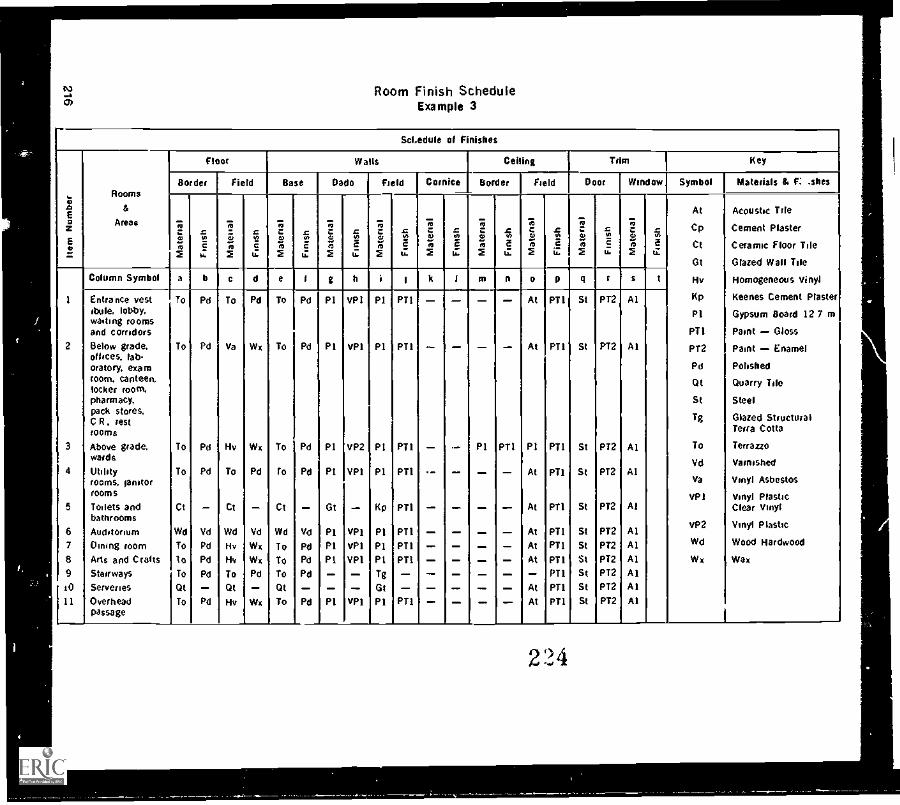
12a)
Room Finish ScheduleExample 3
Sci,edule of Finishes
2z
Rooms
&
Areas
Floor Waits Ceiling Trim Key
Border Field Base I Dade I Field Cornice Border Field Door Window Symbol Materials & c: shes
ry azR C 0 c
i.a c
i.02
ccto 0 a
.%2
Vbc7,
41Ic.1,
At
Cp
Ct
Gt
Hv
Kp
PI
PTI
PT2
Pd
Qt
St
Tg
To
Vd
Va
VPI
VP2
Wd
Wx
Acoustic Trle
Cement Plaster
Ceramic Floor Tile
Glazed Wall Tile
Homogeneous Vinyl
Keenes Cement Plaster
Gypsum Board 127 m
Paint Gloss
Paint Enamel
Polished
Quarry Tile
Steel
Glazed StructuralTerra Cotta
Terrazzo
Varnished
Vinyl Asbestos
Vinyl PlasticClear Vinyl
Vinyl Plastic
Wood Hardwood
Wax
2
3
4
5
7
8
9JO
11
Column Symbol a b c d e I g h i I k I m n o p q I s t
Entrance vestibule, lobby,wasting roomsand corridorsBelow grade,offices, lab-oratory, examroom, canteen,locker room,pharmacy,pack stores.C R, restrooms
Above grade,wards
Utilityrooms, genitorrooms
Toilets andbathroomsAuditorium(lining roomArts and CraftsStairways
Serveries
Overheadpassage
To
To
To
To
Ct
Wd
To
toTo
Qt
To
Pd
Pd
Pd
Pd
Vd
Pd
Pd
Pd
Pd
To
Va
Hv
To
Ct
Wd
Hv
Hy
To
Qt
Hv
Pd
Wx
Wx
Pd
Vd
Wx
Wx
Pd
Wx
To
To
To
to
Ct
Wd
To
To
To
Qt
To
Pd
Pd
Pd
Pd
Vd
Pd
Pd
Pd
Pd
P1
P1
P1
PI
Gt
PIPIPI
PI
VPI
VP1
VP2
VP1
VP1
VP1
VP1
VPI
PI
P1
PI
P1
Kp
P1
PIPITg
Gt
PI
PTI
PT1
PTI
PT1
PT1
PT1
PT1
PTI
PT1
P1 PT1
At
Al
PI
At
At
AtAtAt
AtAt
P11
PT1
PT1
PT1
PT1
PT1
PT1
PT1
PT1
PTI
PT1
St
St
St
St
St
St
St
StStStSt
PT2
P12
PT2
PT2
PT2
PT2
PT2
PT2
PT2
PT2
PT2
Al
Al
Al
Al
At
AlAlAlAlAlAl
224
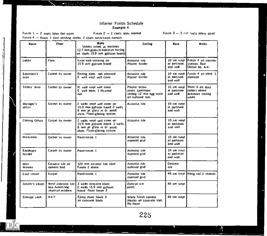
Finish 1 2 coats latex Nat Paint
interior Finish ScheduleExample 4
Finish 2 2 coats latex enamelFinish 4 Stain. 1 coat sandirig sealer. 2 coats satinfinish varnish
Finish 3 2 vs!' -oa:s epoxy paint
Room Floor WallsUnless noted, at masonry
12.7 mm gypsum board on furringon studs 15.9 mm gypsum board
Ceiling Base Notes
Lobby FloorI.
Vinyl wall covering on159 mm gypsum board
Acoustic tilePlaster border
I110 cm vinylat pa'titionand wall
Finish 4 on countershelves. Rail(detail Sh A4;
Secretary'sarea
Carpet by owner Railing elem. oak plywoodE wall vinyl wall cover
Acoustic tilePlaster border
10 cm vinylat partitionand wall
Finish 4 on elem 1
plywood
Tellers' Area Carpet by owner N. wall vinyl wall coverE wall elem. 1 plywoodoak
Plaster belowfoists. Luminousceiling 12 mm egg crateon exposed tees.
10 cm vinylat partitionand wall
Paint 3 arc ductcollars aboveluminous ceilingwhite
Manager'soffice
Carpet by owner 2 walls vinyl wall cover on15.9 mm gypsum board 2 walls6 mm p1 glass in br anod.alum. Flushglazing system.
Acoustic tile 10 cm vinylat partitionand wall
Closing Office Carpet by owner 2 walls vinyl wall cover on15.9 mm gypsum board 2 wails6 mm p1 glass in br anod,alum. Flushglazing system
Acoustic the 10 cm vinylat partitionand wall
Workroom Carpet by owner Paintfinish 1 Acoustic tileexposed grid
Acoustic tileexposed grid
10 cm vinylat partitionand wall
r 10 cm vinylat partitionand wall
Employeelounge
Carpet by owner Paint-finish 1
MenWomen
Ceramic tile oncement bed
120 mm ceramic the wainFinish 2 above
Acoustic pileexposed grid
Ceramictile
Coat closet Carpet Paintfinish 1 Acoustic tileexposed grid
40 cm vinyl Hang rod 2 shelves
Janitors closet Vinyl asbestos tilelike Armstrongimperial modern
2 walls concrete block2 walls 159 mm gypsumboard Paint finish 3
Ditto-at a wfoists
40 cm vinyl
Storage vault VAT Epoxy paint finish 3on concrete block
White finish cementplaster on concrete slab.No paint
40 cm vinyl
225
Module 8
EXERCISE
1. What information does a drywall finisher look for on a finishing schedule?2. What is the difference between finishing a wall for flat paint and a wall for gloss
paint?3. What effect does humidity have on filler drying time?4. If wallboard is put on wood studs that have a high moisture Content, what can be
the result?5. What :s the minimum temperature for proper drying of slow setting filler?6. Besides heat, what else is needed to dry filler?7. Why should the temperature be fairly constant when filler is drying?8. Name three problems that can occur with wood framing.9. Name five problems finishers can find with the boarding.
10. What is the recommended height for stacking y.)IIboard?11. What is the best way to treat stains on wallboard'12. What should you do before removing masking tape .ot ')as protected a surface
from filler?13. Where would you find the brand name of fillers to use for a job?14. What is the maximum amount of moisture content that wood studs and wallboard
should have?15. What is the ideal humidity range for proper drying of filler?16 ..msulting the drying chart given in this module, how long would it take a coat of
hen the temperature is 15°C and the relative humidity is 50%?i io the :.verag :droom, what electrical wires and boxes should be in place at thetime the w. :. --I is being taped?
218 226'
Working EfficientlyMODULE 9
INTRODUCTION
Because wages compose the bulk of the cost of drywall jobs, it is important thatfontsf-ers work efficiently. This is not to say that the faster the work is done the more ef-ficient it is. Speed must be combined with quality to make a job efficient. If thefinishers are working efficiently, it follows that the employer makes money and the em-ployees are kept working.
This module is not intended as a lesson on "getting in good with the boss" or pace set-ting, but rather on how important it is to keep costs down. If costs become too high be-cause of poor employee planning, a more efficient crew may be found to complete thejob.
Organizing Tools and EquipmentDepending on the size of tilt job, there are always certain tools or pieces of equipmentrequired to start the job, other tools or equipment to complete the work. and stillanother set to clean up. These tools and pieces of equipment should be on the jobbefore the crew gets there, and should be in good working order. It is usually theresponsibility of the person in charge of the job to order equipment. This requiresknowledge of what the job involves in different types of buildings, e.g., single ormultiple dwellings, commercial blocks, warehouses, and what tools and equipment arerequired for each. For example, a commercial building with high walls may require theuse of a scaffold, or a series of scaffolds to elevate an entire work floor. All frames.flooring, braces, and safety rails should be at the job site and set up on the morning ofthe first work day. Taping and filling machines should be in good working order. Ifequipment is not in good repair, the crew could be left standing around doing nothingor working on something that does not produce a finished product. Wages for lost orunproductive time add up fast. It is conceivable that a company's estimated profit for ajob can be eaten up in time wasted by poor planning.
The efficient worker shows up on the job with all needed tools in good shape and in atool box so that they can be readily located. Time spent running to a car to get a trowelor a knife costs money.
Tools and equipment should be centrally located and secured in such a way that theycannot be lost. Taping and finishing tools should be kept near the mixing area. Whennot in use, they should be kept in a locked room or container for insurance purposes,since insurance covers only those tools that can be proved were properly protected.
227219
Module 9
Identifying CostEfficient Use Of MaterialsThere are two ways to use materials efficiently. One is to use only the quantities thatare needed for the job; the other is to use the correct types of materials. Using only therequired quantities means a saving in material costs. For example, ordering cornerbeads in lengths that can be cut for outside corners and the excess used for headers inclosets reduces waste. Ordering 2.1 m beads instead of 2.4 beads for closet returns ordoor openings reduces waste. For some window returns ordering 2.4 or 3 m pieces willeliminate all waste. When a long run is required, the longer the pieces of bead the lesstime spent in joining them.
By choosing the correct material for the job you can make savings in both materialsand labor. Deep fills of more than 3 mm should be done with fastset filler to ensurethat the filler is hard enough to re-coat in minimum time; with fast-set this can beanywhere from 15 to 90 minutes. To do the same job slow-set filler can take from oneto three days to dry, and then shrinkage may necessitate an extra coat to make sure thefill is level. Thus, if the proper material is used for deep fills, time is not wasted puttingon an extra coat or waiting for the filler to dry.
Checking WorkEach worker on a crew is a part of a larger system and thus if individual workers are notdoing their part the system as a whole will be affected.
When you are assigned a task you carry the responsibility of completing that assign-ment. Since most persons will miss a few spots here and there, it is a good idea todevelop a habit of checking the work after completing it. The few minutes that thischeck will take will save time in the long run. To make the check walk around the roomin the reverse direction from which you came. In this way, you view the work from anopposite angle and you will see misses and errors more eaeily. Remember even thosewho have been in the trade a long time will miss something.
Consider the result of forgetting to do a set of fasteners. It could take up to three hoursto put three coats of filler on the fasteners. If someone has to stay to do this it meansthere is a three hour delay just for a set of fasteners. Or if someone is sent back to thejob there is the three hours plus travelling time. To avoid such delays and additionalcosts, make a quick check of your work; it is a good safeguard.
If you are following someone else on a system where each of you does a specific task,and you notice that something was missed, it is usually more efficient to do the misseditem yourself rather than waste time getting your co-worker to come back. This is not tosay that you should always be covering up the mistakes of others, but rather to do sowhen it is within reason. If the mistakes of co-workers become frequent then youshould tactfully mention the neglect to them.
The Individual Versus The Team ApproachThere are two main ways for crews to approach a drywall job. the individual approachand the team approach. In the individual approach a worker does all phases of thefinishing job from start to end. With the team approach a worker does one phase of thejob, for example the taping.
Both approaches have their advantages and disadvantages. The individual approachtends to produce good quality work, but it can be slower because a worker is not as
220
228
Working Efficiently
practiced in each of the four phases as someone who does only one of the phases allthe time, and because of the monotony created by the length of time it takes to com-plete the Job. The team approach tends to produce faster work but the overall qualitymay not be as good. For the team approach it is important that the crew have a commonidea of how the work shouid be done. Most finishers take pride in their work and canbecome quite discouraged when the work done before them is not up to their stand-ards. Similar standards are most often developed amongst crews who have workedtogether for a while. Individual approach crews usually work best with a relatively in-flexible supervisor who checks behind each worker to see that the job is complete.Team approach crews usually require a more flexible supervisor.
Finishers will have their own particular strengths and preferences. Foremen and super-visors should learn what these are to get maximum production from their work crews.
Work SystemsDifferent types of buildings require different work systems. Houses are often done on afour-day system. The first day is for taping and first-coating of fasteners and beads; thesecond is for second-coating fasteners and beads, and first-coating flats and butts andone side of the angles if the job 1^, done by hand; the third day is for polish-coating allremaining work; the fourth day is for texturing ceilings and for sanding. It should takeone day for one worker to complete one coat on an average-size house (460 m2). Ifthere are two or more houses side by side, the crew is usually increased and the workproceeds as follows. on day one tape and first-coat all the houses; on day two secondcoat the houses, and so on. In this way all the houses will be completed on the sameday. Note that a coat is not started on house two until the coat has been completed onhouse one.
In a multiple unit building the system can be different. One system is to regard suitesas separate units and work through the building unit by unit. The disadvantage of thissystem is that all the suites on a floor may not get finished on the same d..y. A morecommon system is to regard an entire floor as a unit of work where the crew completesone coat at one time on all suites on the floor. For example, everyone on the crew willfill bead until the floor is finished. Then the crew splits up to do the nails and flats. Thework force is adjusted so that one floor is completed in one week. This system isdependent upon having reliable crew members who don't miss work days. If days aremissed then this system can become inefficient and costly.
Commercial buildings, especially large shopping centres, must be divided into sec-tions. Usually the schedule of the site is such that as one trade finishes in one sectionthe next moves in. Therefore, it is important that the drywall contractor finishes a sec-tion on schedule so that the project is not held up.
SUMMARY
All equipment required to complete a job should be on the job site before the crewarrives.
All equipment should be in good working order before it is delivered to the site.An efficient finisher develops a self-checking system to ensure that nothing ismissed.
6 ro use materials efficiently, you have to order both the right amount and thecorrect type.
221
229
Module 9
There are four main phases to consider when organizing work systems for adrywall job:1. Tape, and first coat bead and fasteners.2. Second coat all fasteners, bead and tape.3. Polish coat.4. Texture ceilings and sand the walls.The work supervisor must consider the size and work schedule of the job to deter-mine how many workers are needed and how large the unit of work should be.There are two basic approaches to doing a drywall job: the individual approachand the team approach.The most common way of finishing multiple unit buildings is to complete onefloor at a time.
EXERCISE
1. Name three ways of saving money on a drywall finishing job.2. What habit should a finisher develop that will minimize misses?3. What is a suitable crew size for finishing four average size houses in one week?4. What are the four work phases to consider when choosing a work system?5. What is an advantage and a disadvantage of each of the following ways of
organizing crews?Individual approach.Team approach.
222 230
4
,
Maintenance ofTools and Machines
MODULE 10
INTRODUCTION
Some people use their tools as an excuse for doing poor work. They should, however,blame themselves because they are the ones responsible for keeping their tools in goodworking condition. Tools that are well maintained save time and money in the long run.
Complete maintenance information for all the equipment used in the drywall industrycannot be provided here, but following are some general maintenance rules applying tomost drywall tools and machines.
Maintaining Hand ToolsAfter use, hand tools should be cleaned and dried so that rust does not form on them.When not in use they should be stored in a locked tool box. Since most nicks and roughedges on tools occur while transporting tools, the tool box should have compartmentsor dividers to prevent the tools from bouncing around or coming in contact with oneanother.
Worn blade/ / Filed blade
Areaof contact
Pointof contact
Figure 10-1Blade Contact
Trowels and KnivesTrowels and knives should be kept square so they will cut through the filler. The more ablade is worn the greater becomes the surface area of metal that contacts the filler(Figure 10-1). This means that to compensate for the poor cutting ability of the blade,the applicator must apply more pressure. Thus more mud is removed, leaving the fillhollow. Check your work. Do your tools leave a poorly feathered edge? Do your fillsalways seem to be hollow? If so, you deserve a break. buy a single-cut, mill bastard file
231223
Module 10
and file the blades square on your filling tools. And how about the tapes that you wipe?Do they always seem to be too high and difficult to fill? It could be that the knife youare using has worn sharp and therefore is not pushing the tape tight to the wall.
Worn tools make your work harder and the quality poorer; they may even cost you yourjob. Filed tools, on the other hand, make your work easier and improve the quality ofyour work.
Straightedge
[This trowel should be Slightly worn corners
ground before being filed indicate normal wear
Figure 10-2Check for Blade Straightness
Before filing the blade, check it with a straightedge to see how badly the edge is worn(Figure 10-2). If the edge is too badly worn it may be necessary to use a grinder torough out a straight edge on the blade before filing. Run the blade through the grinderfor the full length of the blade on each pass. Although the blade tends to warp as itheats up from the grinding, it returns to normal as it cools. Do not, however, heat theblade until it turns blue as this causes loss of temper resulting in quicker wear.Once the blade is roughly straight, select a single-cut file (Figure 10-3) and fasten thefile to a surface so that you can push the blade along the file without it moving. Oneway of fastening the file is to hammer nails in tight to the heel and tip of the file, thenbend them over the file. Place the blade firmly on the file, keeping the blade per-pendicular to the file. Press down with even pressure on the blade so that it does notskip and push forward until the pass is finished. Lift the blade straight up from the fileand repeat the pass (Figure 10-4). Note that if you move the blade too fast it will rockand you will not get a straight edge.
After filing, remove any burrs with sandpaper. This applies to all trowels and knives.You should use sandpaper rather than filing off the burrs because the filing willdecrease the width of the knife. By filing the blades of your tools once a week you willkeep them in good condition. Besides maintaining the blades, make sure the handles oftrowels and knives are on tight so they don't move while you are working.
Hawks
Hawks may also be filed if they are worn. A worn hawk begins to take on a star shape.
224
232
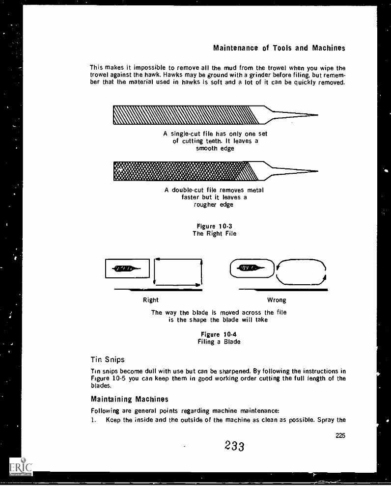
Maintenance of Tools and Machines
This makes it impossible to remove all the mud from the trowel when you wipe thetrowel against the hawk. Hawks may be ground with a grinder before filing, but remem-ber that the material used in hawks is soft and a lot of it can be quickly removed.
A single-cut file has only one setof cutting teeth. It leaves a
smooth edge
A double-cut file removes metalfaster but it leaves a
rougher edge
Figure 10-3The Right File
r 1 (41=-)c---DRight Wrong
The way the blade is moved across the fileis the shape the blade will take
Figure 10-4Filing a Blade
Tin SnipsTin snips become dull with use but can be sharpened. By following the instructions inFigure 10-5 you can keep them in good working order cutting the full length of theblades.
Maintaining MachinesFollowing are general points regarding machine maintenance:1. Keep the inside and the outside of the machine as clean as possible. Spray the
225
233
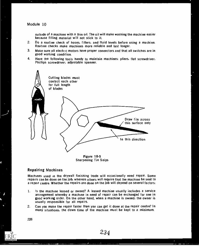
Module 10
outside of a machine with a thin oil. The oil will make washing the machine easierbecause filling material will not stick to it.
2. Do a routine check of hoses, filters, and fluid levels before using a machine.Routine checks make machines more reliable and last longer.
3. Make sure all electric motors have proper connectors and that all switches are ingood working condition.
4. Have the following tools handy to maintain machines: pliers, flat screwdriver,Phillips screwdriver, adjustable spanner.
Cutting blades mustcontact each otherfor full lengthof blades
Draw file acrossthis surface only
Figure 10-5Sharpening Tin Snips
In this direction
Repairing Machines
Machines used in the drywall finishing trade will occasionally need repair. Somerepairs can be done on the job, whereas others will require that the machine be sent toa repair centre. Whether the repairs are done on the job will depend on several factors:
1. Is the machine leased or owned? A leased machine usually includes a servicearrangement whereby a machine in need of repair can be exchanged for one ingood working order. On the other hand, when a machine is owned, the owner isusually responsible for all repairs.
2. Can you make the repair faster than you can get it done at the repair centre? Inmany situations, the down time of the machine must be kept to a minimum.
226
234
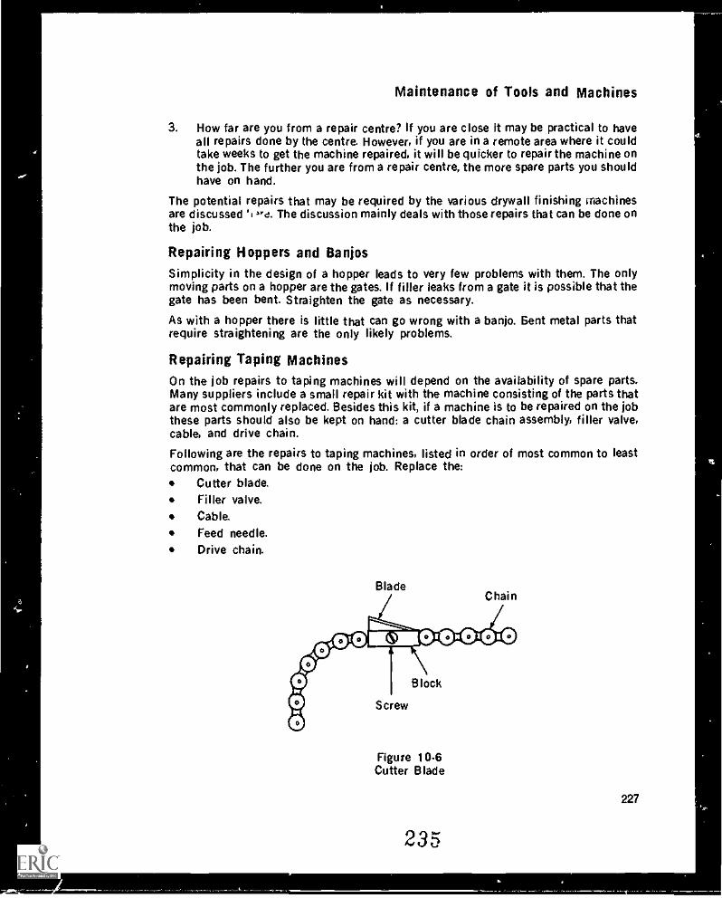
Maintenance of Tools and Machines
3. How far are you from a repair centre? If you are close it may be practical to haveall repairs done by the centre. However, if you are in a remote area where it couldtake weeks to get the machine repaired, it will be quicker to repair the machine onthe job. The further you are from a repair centre, the more spare parts you shouldhave on hand.
The potential repairs that may be required by the various drywall finishing machinesare discussed '1 zre. The discussion mainly deals with those repairs that can be done onthe job.
Repairing Hoppers and BanjosSimplicity in the design of a hopper leads to very few problems with them. The onlymoving parts on a hopper are the gates. If filler leaks from a gate it is possible that thegate has been bent. Straighten the gate as necessary.
As with a hopper there is little that can go wrong with a banjo. Bent metal parts thatrequire straightening are the only likely problems.
Repairing Taping MachinesOn the job repairs to taping machines will depend on the availability of spare parts.Many suppliers include a small repair kit with the machine consisting of the parts thatare most commonly replaced. Besides this kit, if a machine is to be repaired on the jobthese parts should also be kept on hand: a cutter blade chain assembly, filler valve,cable, and drive chain.
Following are the repairs to taping machines, listed in order of most common to leastcommon, that can be done on the job. Replace the:
Cutter blade.Filler valve.Cable.
Feed needle.Drive chain.
Figure 10.6Cutter Blade
235
227
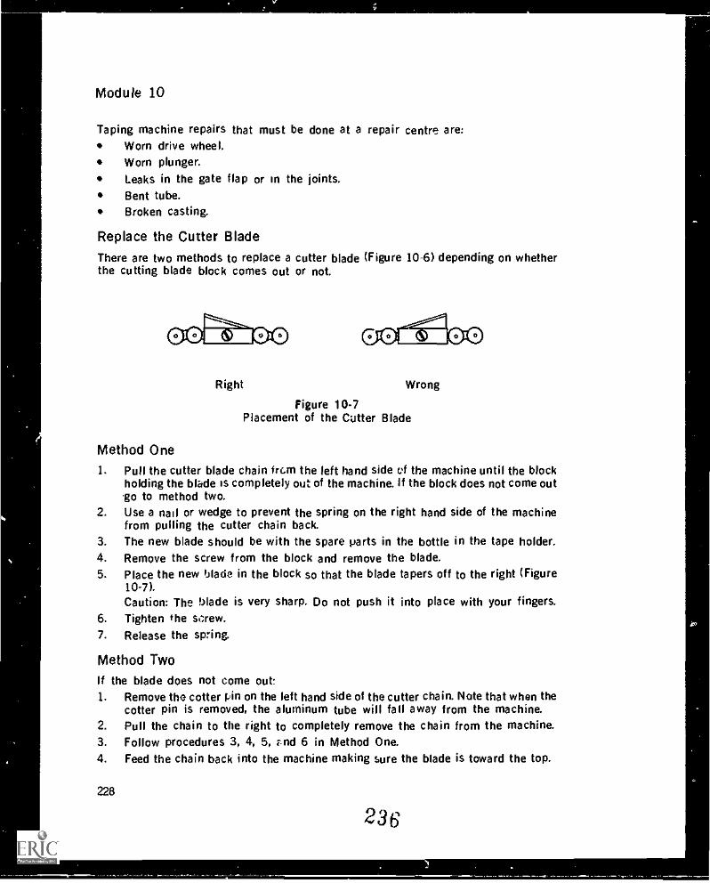
Module 10
Taping machine repairs that must be done at a repair centre are:Worn drive wheel.Worn plunger.Leaks in the gate flap or in the joints.Bent tube.Broken casting.
Replace the Cutter BladeThere are two methods to replace a cutter blade (Figure 10-6) depending on whetherthe cutting blade block comes out or not.
Right Wrong
Figure 10-7Placement of the Cutter Blade
Method One1. Pull the cutter blade chain frc.m the left hand side c.%f the machine until the block
holding the blade is completely out of the machine. If the block does not come outgo to method two.
2. Use a nail or wedge to prevent the spring on the right hand side of the machinefrom pulling the cutter chain back.
3. The new blade should be with the spare parts in the bottle in the tape holder.4. Remove the screw from the block and remove the blade.5. Place the new blade in the block so that the blade tapers off to the right (Figure
10-7).Caution: The blade is very sharp. Do not push it into place with your fingers.
6. Tighten the screw.7. Release the spring.
Method TwoIf the blade does not come out:1. Remove the cotter pin on the left hand side of the cutter chain. Nate that when the
cotter pin is removed, the aluminum tube will fall away from the machine.2. Pull the chain to the right to completely remove the chain from the machine.3. Follow procedures 3, 4, 5, rnd 6 in Method One.4. Feed the chain back into the machine making sure the blade is toward the top.
228
236
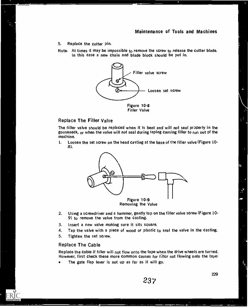
Maintenance of Tools and Machines
5. Replace the cotter pin.
Note: At times it may be impossible to remove the screw to release the cutter blade.In this case a new chain and blade block should be put in.
Filler valve screw
Loosen set screw
Figure 10.8Filler Valve
Replace The Filler ValveThe filler valve should be replaced when it is bent and will not seal properly in thegooseneck, or when the valve will not seal during taping causing filler to run out of themachine.1. Loosen the set screw on the head casting at the base of the filler valve (Figure 10-
8).
Figure 10-9Removing the Valve
2. Using a screwdriver and a hammer, gently tap on the filler valve screw (Figure 10-9) to remove the valve from the casting.
3. Insert a new valve making sure it sits square.4. Tap the valve with a piece of wood or plastic to seal the valve in the casting.5. Tighten the set screw.
Replace The CableReplace the cable if filler will not flow onto the tape when the drive wheels are turned.However, first check these more common causes for Mier not flowing onto the tape:
The gate flap lever is not up as far as it will go.
229
237
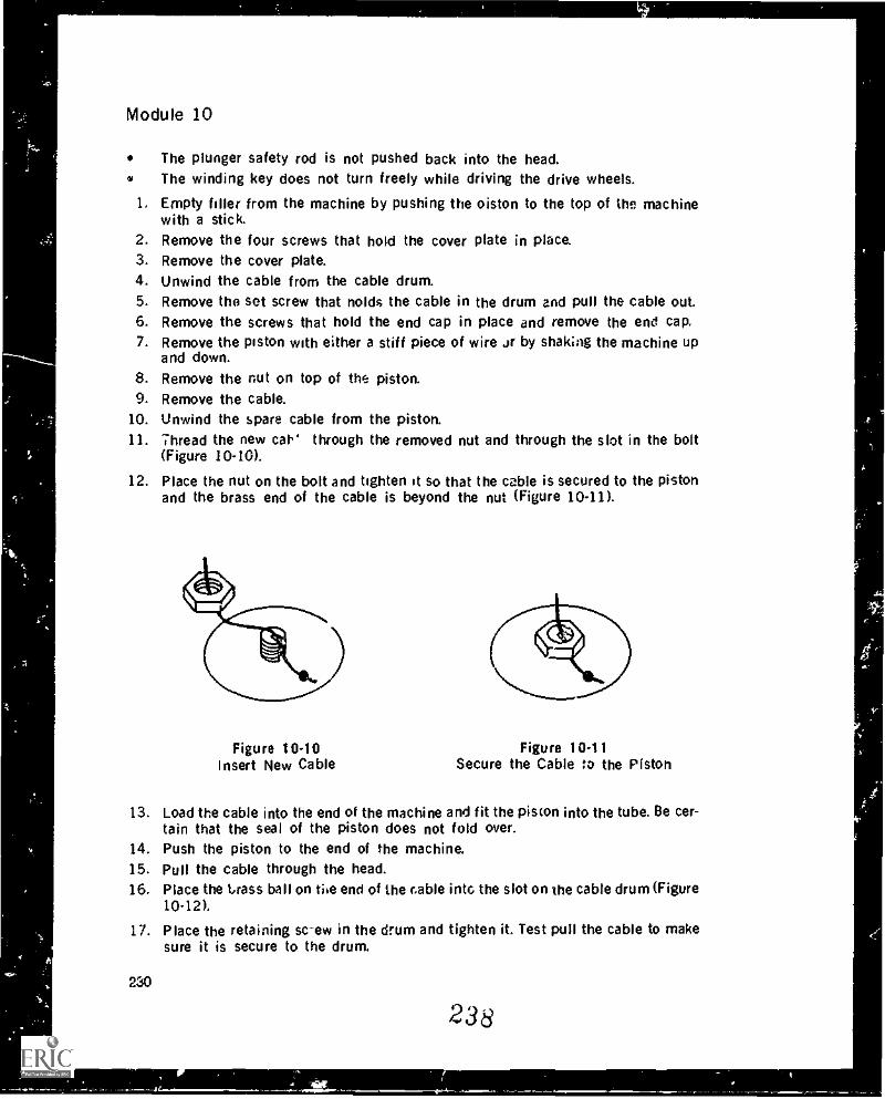
Module 10
The plunger safety rod is not pushed back into the head.The winding key does not turn freely while driving the drive wheels.
1, Empty filler from the machine by pushing the oiston to the top of the machinewith a stick.
2. Remove the four screws that hold the cover plate in place.3. Remove the cover plate.4. Unwind the cable from the cable drum.5. Remove the sot screw that nolds the cable in the drum and pull the cable out.6. Remove the screws that hold the end cap in place and remove the end cap.7. Remove the piston with either a stiff piece of wire Jr by shaking the machine up
and down.8. Remove the nut on top of the piston.9. Remove the cable.
10. Unwind the spare cable from the piston.11. 7hread the new car through the removed nut and through the slot in the bolt
(Figure 10-10).
12. Place the nut on the bolt and tighten it so that the cable is secured to the pistonand the brass end of the cable is beyond the nut (Figure 10-11).
Figure 10-10Insert New Cable
Figure 10-11Secure the Cable to the Piston
13. Load the cable into the end of the machine and fit the piston into the tube. Be cer-tain that the seal of the piston does not fold over.
14. Push the piston to the end of the machine.15. Pull the cable through the head.16. Place the Lrass ball on the end of the cable into the slot on the cable drum (Figure
10-12).
17. Place the retaining screw in the drum and tighten it. Test pull the cable to makesure it is secure to the drum.
230
238
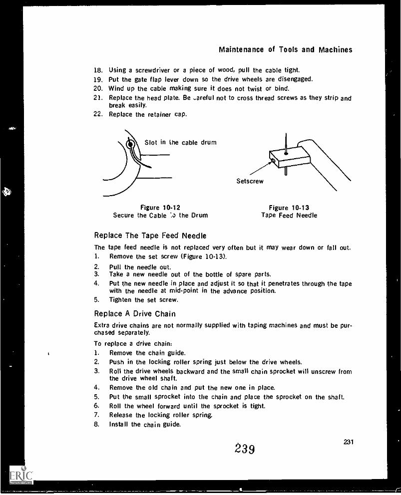
Maintenance of Tools and Machines
18. Using a screwdriver or a piece of wood, pull the cable tight.19. Put the gate flap lever down so the drive wheels are disengaged.20. Wind up the cable making sure it does not twist or bind.21. Replace the head plate. Be ,.areful not to cross thread screws as they strip and
break easily.22. Replace the retainer cap.
Slot in the cable drum
Figure 10-12Secure the Cable the Drum
Figure 10-13Tape Feed Needle
Replace The Tape Feed Needle
The tape feed needle is not replaced very often but it may wear down or fail out.1. Remove the set screw (Figure 10-13).
2. Pull the needle out.3. Take a new needle out of the bottle of spare parts.4. Put the new needle in place and adjust it so that it penetrates through the tape
with the needle at mid-point in the advance position.5. Tighten the set screw.
Replace A Drive ChainExtra drive chains are not normally supplied with taping machines and must be pur-chased separately.
To replace a drive chain:1. Remove the chain guide.2. Push in the locking roller spring just below the drive wheels.3. Roll the drive wheels backward and the small chain sprocket will unscrew from
the drive wheel shaft.4. Remove the old chain and put the new one in place.5. Put the small sprocket into the chain and place the sprocket on the shaft.6. Roll the wheel forward until the sprocket is tight.7. Release the locking roller spring.8. Install the chain guide.
239231
17
Module 10
Repairing Angle Rollers and FlushersTwo types of rollers are available. One has metal rollers and the other plastic or nylonrollers. The metal rollers have bushings that in time wea' out. The plastic rollers alsohave bushings that wear out, and in addition they can develop flat spots on individualrollers from the roller not turning. Repairs to rollers are done at a repair centre; theyare not done on the job.
Some angle flushers are a solid piece of metal bent to a 90° angle, while others havetwo piece casting with springs and replaceable blades. In both cases it is recommendedthat the flushers be sent to a repair centre to be repaired. The degree of precisionrequired for adjustment plus the specialized tools are not readily obtainable on the job.
Repairing Hand and Pole SandersThere are two repairs that can be made on filling boxes on the job: the blade and therubber seals can be replaced. All other repairs should be sent to a repair centre.
To repair the blade:1. Force a nail under the end of the blade and pry up.2. Pull out the blade.3. Clean the slot with the end of the nail.4. Turn the set screws at either end of the brass blade holder so that they will not
contact the blade.5. Check the blade for paint on one edge. The painted edge faces out. If no paint is
present either edge can face out.6. Bend both ends of the blade to form a slight S-shape. Too much of a bend will
make the blade difficult to insert in the slot.7. Place one end of the blade in the slot and work the rest of the blade into place. If
necessary, use a piece of wood or plastic to tap the blade in place.8. Adjust the blade to the proper height.
To replace the rubber seals:1. Remove on the sides of the box the two retaining screws that hold on the back
plate of the box.2. Pull the back plate up and out.3. Remove the rubber seals.4. Install the new rubber seals with the tabs fitting into the slot in the back of the
plate.
5. Fit the back plate in place and wet the rubber seals so they slide into the box.6. Replace the retaining screws.
Hand and Pole SandersThere are two wear points on sanders:
Sandpaper clamps.
Rubber pad.
Sandpaper clamps wear down aryl will eventually not hold the paper in place (Figure
232
240
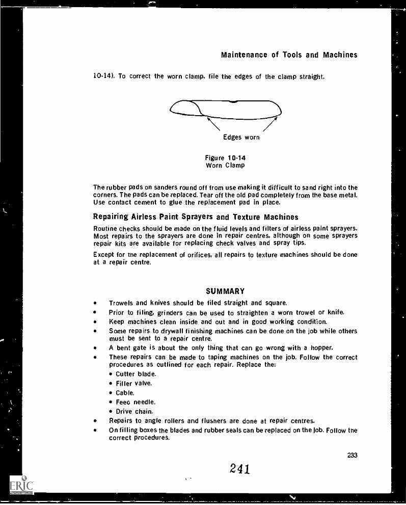
Maintenance of Tools and Machines
10-14). To correct the worn clamp, file the edges of the clamp straight.
c,_,_ .10.
___D\ /Edges worn
Figure 10-14Worn Clamp
The rubber pads on sanders round off from use making it difficult to sand right into thecorners. The pads can be replaced. Tear off the old pad completely from the base metal.Use contact cement to glue the replacement pad in place.
Repairing Airless Paint Sprayers and Texture MachinesRoutine checks should be made on the fluid levels and filters of airless paint sprayers.Most repairs to the sprayers are done in repair centres, although on some sprayersrepair kits are available for replacing check valves and spray tips.
Except for the replacement of orifices, all repairs to texture machines should be doneat a repair centre.
SUMMARY
Trowels and knives should be filed straight and square.Prior to filing, grinders can be used to straighten a worn trowel or knife.Keep machines clean inside and out and in good working condition.Some repairs to drywall finishing machines can be done on the job while othersmust be sent to a repair centre.A bent gate is about the only thing that can go wrong with a hopper.These repairs can be made to taping machines on the job. Follow the correctprocedures as outlined for each repair. Replace the:
Cutter blade.Filler valve.Cable.
Feeo needle.Drive chain.
Repairs to angle rollers and flusriers are done at repair centres.On filling boxes the blades and rubber seals can be replaced on the job. Follow thecorrect procedures.
241233
Module 10
Repairs that can be made to sanders on the jub are grinding and filing the clampsstraight and replacing the rubber pad.Repairs to paint sprayers and texture machines are generally done at a repair cen-tre.
EXERCISE
1. What are two main reasons for keeping hand tools square and straight?2. Are your hand tools square and straight?3. What type of file is used on trowels and knives?4. What manuals are available for your taping machine? Read the maintenance sec-
tion.5. A thin coat of will make a machine easier to clean.6. True or False? Few things ever go wrong with a hopper.7. List five repairs that can be made to a taping machine on the job.8. If a cutter blade breaks, where would you look for a new one?9. The cutter blade in the block should taper to the
10. What tools are needed to replace a filler valve?11. Assuming that all else is correct on the machine, what is the sign that the cable
needs replacing?12. When securing a new cable to the piston, where should the brass end of the cable
be?
13. What must be done after putting a new tape feed needle in place?14. True or False? When replacing a drive chain. the small chain sprocket must be
taken off.15. What are two things that can go wrong with angle rollers?16. What are the two repairs that can be made to filling boxes on the job?17. Where should the tabs of the rubber seals fit on a filling box?18. What should be done when a sander can no longer get right into corners?
234
242
s,
EstimatingMODULE 11
INTRODUCTION
There are two ways of estimating the materials, working time, and dollar figure for adrywall job: from blueprints and from the actual job-site. Blueprints are generally usedprior to construction of the building to estimat- "e. area (number of square metres) ofwallboard surface in the building. Bids on drywa.. .g jobs are often given according toestimates made from blueprints. Once the building is constructed the walls andceilings can be measured and a more accurate estimate of the job can be made. Thismodule describes blueprints then gives the methods of calculating drywall materialsand working time from blueprints and form a job-site inspection. It is intended as an in-troduction to estimating for self-employed individuals or for foreman superb igcrews.
BlueprintsA complete set of blueprints has two parts. the drawings and the specifications. Bothare equally important when determining work procedures and material requirements.The blueprints are visual instructions on how a building is to be constructed. In-formation is drawn to scale, and materials are shown with symbols. The specificationsdetail work procedures, liabilities, specific information about materials, and any otherinfo/ nation that cannot be hand-drawn. Unfortunately drywall is not shown on aseparate drawing, and therefore you must sift through all the blueprint drawings to findcomplete information pertaining to drywall. There are five types of drawings: plot plan,floor plan. elevation, detail and section.
Plot PlanThe plot plan shows how the building is situated on the lot. It gives the geographicalposition according to the points of the compass, as well as the overall dimensions ofthe building and distances from the perimeter of the building to the edge of the lot.This is important in locating the area in the building where you will work, especially ifthe building is not yet built or if it is a large complex such as a shopping centre. Notethat a plot plan is not the same as a survey plan. A survey plan shows only the legaldescription of the land upon which the building is situated.
Floor PlansFloor plans are drawn for each floor in a building. A floor plan shows what a floor of abuilding looks like from above as if there is no roof or ceiling. Floor plans give thelocation, shape and size of the rooms. From floor plans the drywall estimator can get:
235
243
*
mop
Module 11
1. The area of the ceilings, if the ceilings are flat.2. The length of the walls (note that you have to go to the elevation plan for the
height).
3. Which way floor, and therefore the ceiling, joists run.
Elevation DrawingThe elevation plan shows the floors of a building from a side view. From the elevationplan the estimator can get:1. The height of walls. You have to be careful with blueprint wall heights, though, be-
cause changes can occur when the actual walls are built.2. The slope of the ceiling, if there is one.3. How the stairwells are constructed.
Detail DrawingsDetail drawings are large-scale drawings that detail the finishing in certain areas of thebuilding. They are drawn as if you are standing in front of the building looking straightin.
From detail drawings the estimator gets:1. Special trims around windows, doors, skylights, elevator fronts; all 4actors in a
drywall finishing job.2. Any special panelling on walls. In otherwords, which walls aren't drywalled.
Section DrawingsSection drawings are detailed drawings showing the internal construction of certainareas of a building as if the surface had been cut to reveal what is behind it. From sec-tion drawings the estimator can get:1. The type of framing: metal or wood.2. The type and thickness of wallboard.3. If the wallboard is attached directly to the framing or if special sound-reducing
framing methods are used.
By combining the information from all five blueprint drawings you can piece togetherinformation about the drywall job and get a general picture of what the job is like.
Finish Schedulesrinish schedules are included in the blueprints and may be drawn as a grid, with therooms on one axis and the walls, ceilings, floors. etc., on the other. The finish scheduletells you what material is or, a surface and what kind of finish goes on the material. It isa general information sheet from which you can determine what areas are drywalledand what amount of drywall finishing is required to prepare the wallboard for its finaldecoration.
A finish schedule does not give specific information on finishes such as the color ofpaint or the thickness of a vinyl wall covering. This information is found in thespecifications. See Module Eight for examples of finishing schedules.
236
244a r
Estimating
SpecificationsThe specifications are broken down into headings to help you readily locate in-formation. Not all architects will include a section on drywall in their specificationsand even if they do have one, all the required information on drywall may notnecessarily be there. A close reading of the specifications will be necessary to locateall information pertaining to drywall As you read, it is a good idea to make notes listingall the headings that contain information regarding drywall. You may also find it help-ful to underline or highlight pertinent information for quick reference.
Specifications can also be used to cross-check the architects' instructions. Be surethat when reading blueprints or specifications you make no assumptions. Read what ispresented tc you. If it does not make sense, for one reason or another, contact the ar-ch;'....r* for an explanation.
In addition to blueprint specifications it is necessary to have a working knowledge ofspecifications produced by government agencies, manufacturers and related trades.These must be compared to the architect's specifications so that any discrepancies canbe noted and checked. Generally speaking, there is a hierarchy of specification withthose above overruling those below. A typical hierarchy could be:1. Local building codes2. National building codes.3. Architect's specifications.4. Manufacturer's specifications.5. Local drywall association's specifications.
The order of the hierarchy can change from job to job depending on such factors as thetype of local government, the knowledge of the local engineering department, and thetype of building and its source of funding. Mortgage company or national agency stand-ards like CMHA and CSA can also effect the order. Be aware of the variousspecifications and their priority of importance.
Calculating Areas From Blueprints (Doing A "Take-Off")To calculate areas you will need to use the formula for the area of a rectangle, Arealength times width. A calculator will save a lot of time. Flat ceiling areas are found bymultiplying the length of the room by its width. Calculating some ceiling areas such asroom one in Figure 11-1 is straight forward (3 m x 4 m = 12 m2). Other ceilings aremore of a problem, e.g., room 5, the right angle hallway. No measurements are given forthe hallway, you have to find them by looking at the measurements of the adjoiningrooms. The vertical leg of the hallway is 3 m + 1 m = 4 m long and 1 m wide. Thehorizontal leg is 3 m by 1 m. The area of the hallway therefore is (4 m x 1 m) + (3 m x1 111) -= 7 m2.
The areas of the ceilings in Figure 11-1 are calculated as follows:
Room 1. 3 mx 4 m= 12 m2Room 2. 3m x 5m = 15 m2Room 3. 3 m x 3 m = 9m2Room 4. 3 m x 3 m = 9m2
237
245
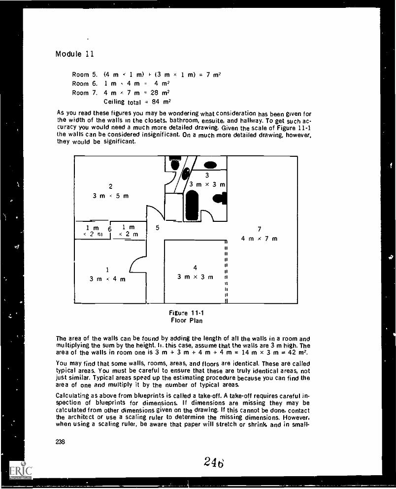
Wr
Module 11
Room 5. (4 m < 1 m) 4- (3 m 1 m) = 7 m2Room 6. 1 m 4 m = 4m2Room 7. 4 m x 7 m 28 m2
Ceiling total = 84 m2
As you read these figures you may be wondering what consideration has been given forthe width of the walls in the closets, bathroom, ensuite, and hallway. To get such ac-curacy you would need a much more detailed drawing. Given the scale of Figure 11-1the walls can be considered insignificant. On a much more detailed drawing, however,they would be significant.
2
3 m < 5 m
I m 6 l< 2 ni 1 x 2 m
1
3 m < 4 m
3m x 3
1
4
3mx3m
tl
7
4mx7m
Figure 11.1Floor Plan
The area of the walls can be found by adding the length of all the walls in a room andmultiplying the sum by the height. h. this case, assume that the walls are 3 m high. Thearea of the walls in room one is 3 m + 3 m+ 4 m+ 4 m= 14 mx 3 m=42 m2.
You may find that some walls, rooms, areas, and floors are identical. These are calledtypical areas. You must be careful to ensure that these are truly identical areas, notjust similar. Typical areas speed up the estimating procedure because you can find thearea of one and multiply it by the number of typical areas.
Calculating as above from blueprints is called a take-off. A take-off requires careful in-spection of blueprints for dimensions. If dimensions are missing they may becalculated from other dimensions given on the drawing. If this cannot be done, contactthe architect or use a scaling ruler to determine the missing dimensions. However,when using a scaling ruler, be aware that paper will stretch or shrink, and in small-
238
246
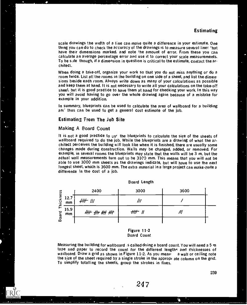
Estimating
scale drawings the width of a line can make quite a difference in your estimate. Onething you can do to check the accuracy of the drawings is to measure several line! thathave their dimensions marked, and note he amount of error. From these you cancalculate an average percentage error and use it to correct your scale measurements.To be site though, if a dimension in question is critical to the estimate, contact the ar-chitect.
When doing a take-off, organize your work so that you do not miss anything or do aroom twice. List all the rooms in the building on one side of a sheet, and list the dimen-sions beside each room. Always write down as many of your calculations as possibleand keep them at hand. It is not necessary to write all your calculations on the take-offsheet, but it is good practice to have them at hand for checking your work. In this wayyou will avoid having to go over the whole drawing again because of a mistake forexample in your addition.
In summary, blueprints can be used to calculate the area of wallboard for a buildingan( thus can be used to get a general cost estimate of the job.
Estimating From The Job Site
Making A Board CountIt is not a good practice to use' the blueprints to calculate the size of the sheets ofwallboard required to do the job. While the blueprints are a drawing of what the ar-chitect perceives the building will look like when it is finished, there are usually somechanges made during construction. Walls may be changed, added, or removed. Forexample, in several rooms the blueprints may state that the walls will be 3 m, but theactual wall measurements turn out to be 3103 mm. This means that you will not beable to use 3000 mm sheets as the drawings indicate, but will have to use the nextlongest sheet, which is 3600 mm. The extra material in a large project can make quite adifference in the cost of a job.
Board Length
2400 3000 3600
12.7mm /t/H /// /// /
15.9mm 1#1- 759t /Hi Of Ifft- II //1
Figure 11-2Board Count
Measuring the building for wallboard ,s called doing a board court. You will need a 5 mtape and paper to record the count for the different lengths and thicknesses ofwailboard. Draw a grid as shown in Figure 11-2. As you meas a wall or ceiling notethe size of the sheet required by a single stroke in the appropt ate column on the grid.To simplify totalling the sheets, group the strokes in fives.
239
. 247
4Module 11
While measuring, you must keep in mind how many joints will be required to cover awall, where they will be placed for structural strength, and where they can be easilyfilled and hidden. Some basic rules to keep in mind are:1. Keep butt joints as close as possible to the end of the walls.2. Butt joints should be staggered a minimum of two studs.3. Keep butt joints away from the middle of the ceiling.4. Don't have butt joints lined up with a light source.5. Walls that Ore 1200 mm or less should have no horizontal joints.6 When possible, there should be no joints above doorways or horizontal joints.7 If a joint is necessary above or below an opening it should be a minimum of 300
mm from the corner.8. Butt joints should not be made where an external wall corner meets the ceiling.
Establish a system for measuring a building. One good way is to measure a completeroom, walls and ceilings, before moving on to the next, and to move clockwise throughthe building.
The most important factor is that you don't miss anything. As a quick check you canuse this rule-of-thumb: multiply level-entry floor areas by 3.5 and the answer should bewithin 20-30 m2 of your board count. For cathedral-entry buildings, multiply the floorarea by 4 to get a rough answer. This method should not, of course, be used to calculatea firm contract price.
If several people measure the same building, most likely they will come up with dif-ferent board counts, thus different estimates of materials and costs. These counts andestimates should, Ihmever, be within 10 per cent of one another unless someone hasmade a major error in calculations or measurements.
Figure 11-2 shows that you would have a total of eight 2400 mm sheets of 12.7 mmboard and 2400 mm sheets of 15.9 mm boards. Thus, when ordering the wallboard, youwould specify:
15.9 mm: 20 1200 x 2400 7 1200 x 3000 3 1200 x 360012.7 mm: 8 1200 x 2400 3 1200 x 3000 1 1200 x 3600
You would not combine the 15.9 mm and 12.7 mm totals for each length because thereis a difference in cost. You would, however, add them together to find the total area ofwallboard in the building.
Calculating Corner Beads and TrimsCorner beads and trims can be bought in 2100, 2400, 3000, and 3600 mm lengths.Every external corner requires a corner bead. Closets that are returned or have a10 mm overlap will require J-bead on the front and corner bead inside. Plastic .1-bead isrequired around windows that are returned. Metal L or .1-bead or plastic .1-bead is usedto finish the edge of wa::board that abutts another surface suc as brick or concrete.On larger projects this information will be found in the specifications. On housingprojects the builder will supply the information.
When measuring bt. .d, always use the length that will create the least amount waste.For example, if you are measuring a chways, you will need four 2100 mm beads for the
240
248
Estimating
uprights. If the width of the archway is 1050 mm, one 2100 mm bead would cover bothheaders. You must think ahead as to where the cut pieces can be used.
Calculating Filler and TapeWhen calculating the amount of filler needed in a building, use the area derived fromthe board count, since it governs the number of joints that will be in the building. Alsouse the total length of bead required.
Use the following guidelines for determining the amount of materials:
110 m of tape per 100 m2 of board (1 roll of tape has 150 m)1 box of 2 bags of taping filler per 100 m21 box or 1 bag of topping filler per 100 m22 boxes of pre-mix filler per 100 m22 bags or 1 box of pre-mix filler per 30 m of bead3 bags of ail-purpose filler per 100 m25 L of paint per 30 m2I bag of texture per 30 m2
For example, if you have 450 m2 of wallboard with 90 m of bead you would require:
450 m2 495 m1. 110 m = 495 m = 3.3 rolls of tape.
100 m2 150 m/roll
450 m22. x 1 box = 4.5 boxes of taping filler.
100 m2
3.450 m2 x 1 box = 4.5 boxes of topping filler.100 m2
0m4. x 1 box = 3 boxes of filler for bead.
30 m2
or, if you were using all-purpose filler:
450 m2 x 3 bags = 13.5 bags of filler.100 m2
Naturally you cannot buy 3.3 rolls of tape or 4.5 boxes of filler. Therefore you mustround off to the next nearest whole number.
Other Factors When Costing A JobIt has been a common practice in the drywall trade to charge the customer the sameamount for materials that the contractor pays for them. This can create a problem be-cause the government will proiably try to charge the contractor sales tax on thematerials assuming that according to normal business practice they will have beenmarked up.
249
241
At
Module 11
The amount of work that one finisher can do is dependent upon many factors, and mayvary from one job, crew, or season to the next. Workers or companies should keep arecord of the type of job and the hours worked to get an accurate time-count for eachtask. Generally, assuming a hopper or taping machine is used, it takes 7.5 hours for onedrywall finisher to completely finish 100 m2 of wallboard. This includes approximately90 m of bead. However, conditions such as high walls, odd shaped rooms, and slopedceilings can reduce this output by as much as 50% or more. Hidden costs andoverhead can drastically affect the final contract price of a job, and will vary from onecompany to another. Hidden costs are costs created by certain job site conditions orprocedures, and cannot be determined from the take-off. Examples of hidden costs are:supervision, moving on and off the site, protection of materials and finished work, andeven the cost of running the job due to the general contractor. You cannot accuratelypredict these costs, but a certain percentage of the total known cost must be allowedfor them in your price.
Overhead is the cost of keeping a business running, including office rental, businesslicences, office help, telephone bills, etc. Overhead is usually calculated on a yearlybasis and converted to a percentage based on the company's income. This percentageis then added on top of each contract price.
Everyone involved in drywall makes estimates, whether it be how much to bid for adrywall job in a large apartment or how much filler to mix for taping. Estimating is partof the job.
SUMMARY
Drywall finishers must read five types of blueprints.Blueprints must have a set of specifications to be complete.Specifications are equally as important as '.he drawings.Any discrepancies between the drawings and the specifications must be resolvedwith the architect.A scaling ruler should not be used to arrive at dimensions from a drawing withoutdetermining the accuracy of the scale of the drawing.Architect's specifications must be compared to those of other regulatory agenciesfor congruency.Check for typical areas.Calculate ceiling areas.Calculate wall areas.Combine wall and ceiling areas for total area.Make a board count.Calculate bead and trims.Calculate filler, tape, texture.One drywall finisher should complete approximately 100 m2 of wallboard in 7'/zhours assuming normal conditions and the taping is done by machine or hopper.Ruleof-thumb for estimating wall and ceiling areas:
level-entry: floor area times 3.5cathedral-entry: floor area times 4
242
250
4
Estimating
Contractors must take into account hidden costs when bidding on a job.
EXERCISE
1. What are the three types of documents that contain information about drywall?2. What is the difference between a take off and a board count?3. Using the formula for rough estimating, calculate the approximate amount of pre-
mix filler for a cathedral entry house with a 120 m2 floor area.4. If it takes 7.5 hours to finish 100 m2 of board, how long will it take to finish an
apartment block that has 6000 m2 of board?5. a. Calculate the total area of wallboard for the house shown in Figure 1-1.
b. Calculate the amount of material required to tape and fill the house (excludebeads).
c. How much paint will it take to undercoat all the ceilings including the closetsand bathrooms?
6. How much texture would you need to do all the ceilings including the closets andbathrooms?
7. How do walls and ceilings higher than 2400 mm affect output?8. List some hidden costs you have encountered on a job.9. Every six months record your m2 output for 7.5 hours work.
243
251
4
Answer Key
MODULE 1
1. So that they can cut through the filler.2. False. Fillers are formulated to meet regional conditions and needs.3. Filler, binder, binder modifiers, additives.4. Binder: internally binds the filler together and externally bonds it to the
wallboard.Additives: give the filling compound desired performance characteristics.
5. Taping filler: high shrinkage, good bond, hard when dry, finish not smooth.Topping filler: low shrinkage, weak bond, fairly soft when dry, smooth finish.
6. a. It sets quickly.b. Deep fills will have little shrinkage or cracking.
7. Prefilling,Taping small jobs.Making deep fills.
B. Free water in the filler.Water combined with the limestone.Water combined with the binder.
9. Because the two fillers could be incompatible and produce a defective filler.Besides, manufacturers' warranties are void when fillers are mixed.
10. a. 200-300 rpm.b. 450 rpm.
11. To improve the workability, flexibility, and crack resistance of the filler.12. False. Filler is added to the water.13. 48 hours.14. The surface of the filler tears.
MODULE 21. 12.7 cm diameter.2. The maximum height of a free-standing scaffold is 3 x minimum base dimension.
The maximum height for remaining on a moving scaffold is 2 x minimum basedimension.
252
245
Answer Key
The maximum height for remaining on a scaffold while moving it yourself is 1.5 xminimum base dimension.
3. The mask should have a NIOSH, MESA or U.S.A. Bureau of Mines approval numberfor pneumoconiosis producing dusts.
4. Set standards for safe working conditions.Provide benefits for injuries.Inspect job sites.Rehabilitate injured workers.
5. Bursitus, tendonitus and back injuries.6. Electrical shock.
Injury caused by a drill trigger sticking and jumping out of your hands.7. When working below a scaffold.
When entering or leaving a job site.8. Trying to maintain production speed while in awkward positions causing strain on
muscles and joints.9. Use a pushing motion when ever possible.
Keep your arm close to your body.Use stilts or scaffolds, don't stretch.Bend your knees, not your back.
MODULE 31. Advantages: Fast to apply
Smooth finishing edge.Disadvantages: Paint chips off the finishing edge.
Can be damaged by bumping.Is affected by movement in the framing.
2. Advantages. A good bond for the entire length of the bead.Is not affected by movement in the framing.Is not easily damaged by bumping.
Disadvantages: Difficult to apply.The finishing edge can be damaged during filling.
3. L-bead: used to trim the rough edges of a long run of wallboard.Jbead: used to trim edges when there is no backing to nail or screw to. The edge
should be no longer than one length of J-bead.Plastic lbead: used as a vapor barrier where wallboard abuts aluminum window
frames.
Veneer bead: used when a corner must be plumbed or straightened.Flexible used on external and internal angles that are greater than 90°.
4. 2385 mm.5 So the finished bead will have a continuous line.6. Slightly less than 45°.
246
253
Answer Key
7. Chalk line.
Straight edge.8. The flange must be cut to allow the bead to bend. The closeness of the cuts
depends on the diameter of the circle.9. Midway up the bead.
10. Double fasten the ends.11. 15 cm to 20 cm.
3 cm.12. Bowed in: at both ends.
Bowed out: at the furthest point out on the bow.13. Pan and knife.
Hopper.
Corner tool and roller.14. The wet paper can easily burr or tear.15. To keep the bead straight.
MODULE 4
Hand Taping1. To reinforce joints and provide a solid, flat surface for further coats of filler.2. Paper tape is 5 cm wide, cream colored, spark-perforated, creased down centre,
and buffed on the edges on one side.3. For patching jobs and on non-bearing, steel-stud walls.4. a. Butts.
b. Flats.
c. Short tapesd. Angles.
5. The tape may be pressed In too far in places to wipe a smooth arc.6. a. Within 1 cm of the ends of joints.
b. Over the flange but not over the finishing edge.c. Within 1 cm of the floor.d. Tight in threeways. Threeway tapes cannct be short.e. Do not cut the tape. Run it right overtop of the outlet.
7. For small jobs and for confined areas.8. Run your finger through the filler to make a trough. The filler should immediately
flow to fill in the trough leaving only a s''ght depression.9. Butts, 2 min
Flats, 3 mm.Angles, 2 mm.
10. b.
247
254
Answer Key
IL To cover holes.To repair damaged wallboard around fasteners.To cover gaps around electrical boxes and plumbing pipes.To reinforce corners in archways.To reinforce Jbead.To bridge gaps between bead and wallboard.
12. Two13. 3 mm.14. Make a sharp crease in the tape before laying it into the angle.15. False. It should be just slightly more.16. The tape and filler are put on the wall in one step.17. Advantage: The hopper holds more filler and therefore more tape can be put
on between refills.Disadvantage: Stilts are needed to do the upper part of the room.
18. True.19. To adjust the amount of filler on the tape.20. Press the handle of a knife, your fingers, or the side of your hand down the crease
mark as the tape is laid into the corner.21. The bottom tape should overlap the upper tape to reduce the likelihood of the
tapes being pulled off.22. The end of the tape has not been pressed tightly against the ceiling wallboard.23. With the hopper, the tape with filler on it is carried to the wall in a pail. With the
banjo, the tape is applied directly to the wall from the banjo.
Machine Taping1. All taping can be done from the floor.
It is a clean method of taping.The production rate is high.
2. Cost of purchase or lease.It is awkward in confined areas.It requires training to use it proficiently.
3. Taping machine, 3 pails, loading pump with a gooseneck attachment, hand knifes,roller, flusher.
4. A screen can plug and it takes time to unplug it. A screen is got necessary becauselumps in filler will pass through the machine without a problem.
5. Do not remove the pump from the pail, but rather pour tiller into the pail.Make sure filler is present at the outlet of the gooseneck before pumping fillerinto the machine.
6. To soften any dry filler so that the parts move freely.7. From the bottom of the roll to the head of the machine.8. That the blade is either dull or broken.
248
25k;
4
Answer Key
9. So that no eller will flow out of the head of the machine.So that the drum, cable, and plunger roll freely during filling.
10. 9 to 11 pumps.11. a. By poking inside the nozzle with a nail or piece of wire.
b. If that doesn't work, by taking the valve out and cleaning it.12. Butts on the ceiling, butts on the walls, flats on the ceiling, flats on the walls,
short tapes and angles.13. a. Turn the winding key a few turns.
b. Run a horizontal wall flat, or if one is not available, an upper butt or a verticalflat.
14. Immerse the head in a pail of water.15. So that you can start the tape exactly where you want it.16. Only for the first 15 cm, then just one wheel should touch.17. To compensate for dragging of the tape along the joint.18. 6 cm.19. The tape will be cut on an angle or the blade will jam.20. Pull the machine back a bit then ahead to the end of the joint, simultaneously
pushing the collar forward to advance the tape.21. The winding key is on the right hand side of the head. If the left hand is on the
collar when taping angles, the winding key will jam against the wallboard.22. To keep the filler flowing onto the tape.23. The left hand. the hand not on the collar.24. Between 45° and 60°.25. You can run the machine with only your left hand on it.26. The machine should bisect the angle.27. Creasing wheel, peel off.28. Immediately after washing when the machine won't be used for a while.29. Because such courtesies contribute to better teamwork and thus better produc-
tion.
Wiping Tapes
1. A fairly wide knife of at least 17 cm with a long handle.2. By wiping tapes in two directions starting at a point between the two ends of the
tape.
3. The pressure applied to the knife and the angle of the knife to the wallboard.4. The tape should be peeled back, filler should be applied, and the tape should be
rewiped.5. A properly wiped tape should:
Be centered on the joint or hole.Have no wrinkles.Be tight to the surface.
256 249
4
Answer Key
Have a skim coat of filler on top.Have feathered edges.
6. The wiper.7. Apply filler to both the top of the wiped side and underneath the side to be wiped.8. Because it is easy to apply too much pressure and leave a dry tape.9. At least 3 cm.
10. More than 60 cm.11. 12 cm.12. Wipe the top half of each side of an angle in one direction, then the bottom half of
each side in the opposite direction.13. The angle will crack where the paper is torn.14. They should bisect the angles.15. The tape will dry and bunch up in the angle.16. The tape will be pushed off to the left.17. 8 cm.18. Wipe the angle with a knife.19. 1 cm.20. To watch for scratches, loose filler, unfeathered edges, unfilled fasteners, or
defects in the wallboard up to the 1200 mm point on the wall.21. 3 strokes. Starting from the centre of the threeway:
a. Left across the ceiling.b. Down the left wall.c. Across the right wall.
22. 3 strokes on each side of the angle:a. Apply a thin coat of filler.b. Wipe the tape tight.c. Feather the edge.
23. The roller is difficult to keep in the centre of the tape. There is usually a gap in thejoint and the roller forces the tape into the gap and accentuates the problem.
24. Whether any cabinet or trim will be put into the angle.That no more than 5 mm of filler will be necessary on top of the tape.
25. Use a straight edge.Use flexible bead in the angle.
MODULE 5
1. Fast-setting Mgr.2. Taping filler is harder to sand and may contain harmful fibres.3. The filling of problem areas before taping or filling begins.4. Pre-filling prevents uneven shrinkage that would require an extra coat to fill.5. a. Gas more than 5 mm.
250
25 v
I I
Answer Key
b. Uneven board surfaces.c. Loose paper, holes around electrical outlets, and plumbing pipes.d. Broken board around fasteners.e. Nails in joints.
6. a. Beads close to the finishing edge.b. Butts on either side of the tape.c. Flats in the middle of the joint.d. Angles in the apex of the angle.
7. a. By sight.b. By touch.c. With a moisture meter.d. From drying charts.
8. Fasteners 3
Fiats 2
Butts --2 or 3Angles 1
Bead 39. Fasteners 2
Flats 1 or 2Butts 2
Angles 0 if wiped properlyBead 2
10. Powdered: overfill to compensate for shrinkage.Pre-mix: level fill.Fast - setting leave hollow to compensate for expansion.
11. The fill should be narrow and not be rippled or ridged. Small air holes (pin holes)are acceptable.
12. The fill should be smooth, wider than the first coat and blemish-free.13. It should be very smooth or slick to the touch, have no blemishes, and should
completely cover the second coat.14 To seal off the wallboart , to remove minor imperfections, and to equalize the suc-
tion of the wallboard.15 When a highly reflective decoration is to be used or when a light source is to shine
across the wall.16. A uniform hazy, white appearance with all previously filled areas visible as a more
solid white.17. Control and pressure.18. Knuckles to the ceiling.19. a. Loading.
b. Featheringc. Removing the excess
258 251
0
Answer Key
d. Cleaning the finishing edges (beads only).20. Decreased increased.
21. To blend the edges of the filler into the wallboard.22. Smooth.23. The fill should be rough sanded.24. Top angles, threeways.25. By arcing it off towards the finishing edge of the bead.26. Gravity pulls the filler into hollow spots.
Filler is less likely to fall on the floor.It is easier on the body to pull upwards.
27. The low side must be built up with filler.28. If possible, try to go around the opening without removing the blade from the wall.
Pivot the blade at the corners.29. On flat surfaces the joint should be flat, whereas on curved surfaces they should
be curved.30. Load the joint so that the low side is built up while very little fill is applied to the
high side..31. Butt: 60-75 cm.
Flat: 30 cm.32. Too much filler has been removed from the flat.33. Adjust the blade, or if that doesn't work, replace the blade.34. First coat 25 cm box.
Second coat 30 cm box.35. As soon as you apply pressure start moving the box.36. The hand closest to the box acts as a fulcrum while pressure is applied by pulling
down on the end of the handle with the other hand.37. Three.38. First coat 13 cm knife.
Second coat 15 cm knife.Third coat 18 cm knife.
39. Smooth finish: Textured Finish:First coat 5 cm box. First coat 5 cm box.Second coat 5 cm box. Second coat 8 cm box.Third coat 8 cm box.
40. To give an adequate width of fill for the 8 cm sander.41. A maximum of 1 mm.42. True.43. False. The bottoms and threeways are always done by hand.44. Place a straight edge along one side of the angle the width of the knife away from
the angle, and run the knife along the edge. Repeat on the other side of the angle.
252
259
Answer Key
45. Approximately 3 mm.46. Take the back off the box.47. a. Vertical angle.
b. Fasteners.
c. Buttsd. Top angle.e. Flats.
48. Depending on the finish to be applied, a 200 W, 150 W, or 100 W bulb in a lightextension cord.
MODULE 61. Hard walls.
Soft ceilings only but not ceilings in high humidity rooms.Self-priming all ceilings.
2. Immediately after the texture is sprayed on.3. False. They require a similar preparation.4. So that the design can be centered on the surface.5. Warm colors tend to stimulate, whereas cool colors tend to relax.6. Mix a large, single batch or blend several small batches together.7. Because the masking tape on the paper apron won't stick to the dusty angle.8. Half the width of the tape.9. With staples.
10. It must have a flat finish, must seal the surface, and must cover (hide) the entiresurface.
11. It will disperse the binder and pigment and decrease the seal and covering ability.12. Painting the angles with a paint brush before the surface is painted with a roller.13. Never point the gun at yourself or at anyone else.
Lock the trigger when the gun is not in use.Release the pressure in the line when the gun is left unattended.
14. Turn the trigger on and off while your hand is moving.15. The paint will be blocked and the pressure will blow the packing ot.t of the tips.16. Machine Factors:
Air pressure.Size of orifice.Thickness of texture.
Application Factors:The distance of the orifice to the surface.The ant, of spray.The speed at which the orifice is moved.
17. True.
264
253
Answer Key
18. When the texture looses its shine and turns dull.19. Evenness of spray is very important as any variation is easily seen.20. Run a knife along the angle.21. Built-up textures, one-coat finishes, staple patterns.22. 5 min.
MODULE 7
1. The filler shrinks at the same rate and no further work needs to be done.2. To soften the film on the filler being repaired so that pulling does not occur.3. True. If you sand parallel to the ridge.4. 5 cm hole laminated tapes;
12 cm hole glued wallboard patch20 cm hole wallboard patch screwed to backing.
5. To ensure a good bond between filler and the painted surface.6. False. The ridged tape if not firm will have to be cut out and the joint prefilled,
taped and filled.7. Press the wal:board tight to the framing.
Reset the fastener or apply a new fastener.Refill with three coats.
8. Plaster has a low Ph and will burn the binder in slow-setting filler. Fast-set acts asa buffer between plaster and slow-set.
9. If texture has been removed, it should be scraped. If texture is discolored, it canbe repainted.
10. Feathered.11. The sealer should dry fast and prevent the stain from bleeding through.12. PVA smoke damage.
Lacquer water soluble stains.13. The framing is not straight (... the plaster is loose.
MODULE 8
1. The type of floor, whether the i base trim, the type of wall finish (flat paint,gloss paint, wallpaper, vinyl pap , tile), whether the ceilings or walls are to betextured, whether there is a dado.
2. Closer attention 'to the surface preparation must be made for gloss paints than forflat paints.
3. The lower the humidity the faster the drying time.4. Nail pops, delzyed shrinkage of filler, wallboard bulges and cracks.5. 12°C.
6. Ventilation.7. If the temperature is significantly lowered, the surface of the filler could dry but
the undQrneath could still be wet If the temperature rises significantly the fillercoult l's. ad properl.,.
254
Answer Key
8. Studs out of alignment, out of plumb walls, sof' studs, studs and plate not aligned,stud centres too far apart to support the board, undersized framing for drops andvalences.
9. Spaces between joints, rippled beads, fastener beads above the surface of theboard, uneven joints, broken core, loose face paper, improper joints (i.e., floatingbutt joints), cracked face paper, gouges, oversized holes for outlets and pipes.
10. No more than 1 m is recommended.11. Coat the stain with lacquer or a spray-bomb varathane plastic.12. Run a knife along the edge of the tape to cut any overlapping filler so that the tape
does not lift c`f filler from the wall when it is removed.13. The written specifications.14. 15%.
15. 40% 70%.16. 24 h.17. A light box and switch and outlets no less than 1.8 m apart on useable wall sur-
faces. All electrical boxes should have wires fed into them.
MODULE 9
1 Have tools and equipment on the job when they are needed.Order the right materials in efficient lengths and quantities.Have the crews organized efficiently.Have an efficient work system.
2. usually check your work in the reverse order in which it was done.3. 4 ,-ersons. Since one person can coat 1 house in a day, then 4 persons could coat
the 4 houses in 4 days.4. a. Tape, and first coat bead and fasteners.
b. Second coat all fasteners, bead and tape.c. Polish coat.d. Texture ceilings and sand the walls.
5. Individual approach: good quality work but likely to be slower than the team ap-proach.
Team approach: high production but the quality may not be as good as the in-dividual approach.
MODULE 10
1. You produce a better job in less time.2. Check that your hand tools are straight and square.3. Single cut mill bastard file.4. Read the maintenance section on your taping machine owner's manual.5. Oil.6. True.
266
262
Answer Key
7. Replace the:Cuttcr b lade.Filler valve.Cable.
Feed needle.Drive chain.
8. In the bottle of spare parts in the tape holder.9. Right.
10. Screwdriver, hammer, piece of wood or plastic.11. Filler will not flow onto the tape when the drive wheels are turned.12. Beyond the nut.13. The needle must be adjusted so that it penetrates through the tape with the needle
at mid-point in the advance position.14. True.
15. Roller bushings wear out and plastic rollers can develop flat spots.16. Replace the blade.
Replace the rubber seals.17. The slot in the back of the back plate.18. Replace the rubber pad.
MODULE 11
1. Blueprints, finish schedules, specifications.2. A take off determines the area of wallboard in a building, whereas a board count
determines the number of sheets by length and thickness.3. The cathedral entry house has approximately:
4 x 120 m2 = 480 m2 of wallboard.
There are 2 boxes of pre-mix filler per 100 m2 of wallboard.
480 x 2 = 9.6 or 10 boxes of pre-mix.100
Remember the 10 boxes is approximate.4. 6000 x 7.5 = 450 hours.
100
256
5. a. Room No.1
23
45
6 3(1
7
Walls(3+3+4+4)(3+3+5+5)(3 +3 +3 +3)
(3+3+3) 3(4+3+4+3)
+1+2+2)+(1+1+2+2)(3+3+4+7+4)
Sub Total:
3
3
3
3
33
==
=
===
=
42 m248 m236 m227 m242 m236 m263 m2
Answer
Ceilings3 x 43 x 53 x 33 x 3
(4x1) + (3x1)(1x2) + (1x2)
4 x 7
Key
= 12m2= 15 m2= 9m2= 9m2= 7 m2= 4 m2= 28 m2
294 m2 84 m2
Total: 378 m2
b. 378 110x = 2.77 or 3 "ils of tape.100 150 mit-oil
bags of taping filler.
378 x 2 = 7.56 or 8 bags.100
bags of topping filler.
378 x 1 = 3.78 or 4 bags.100
bags of all-purpose.
378 x 3 = 11.34 or 12 bags.100
boxes of taping filler.
378 x 1 = 3.78 or 4 boxes.100
boxes of topping filler.
378 x 1 = 3.78 or 4 boxes.100
c. Paint.
84 x 5 = 14 L of paint.30
264257
Answer Key
6. Texture.
84 x 1 = 2.8 or 3 bags of texture.30
7. Walls and ceilings above 2400 mm can increase the finishing time by 50% ormore depending on the height.
8. Examples of hidden costs:Lack of heat, water, power.Having to move from one area to another.The work of preceeding trades is not completed.Breakdowns.
9. Your output should continue to improve for about the first three years, then leveloff.
258
265